Embed Size (px)
Citation preview
5/1/2013
1
Circuit Theory IEE211
Chapter 1Introduction to circuit theory
Introduction• Electrical engineers and electronics technology play an
important role in the peoples daily life.• Electrical engineers design systems that generate, transmit,
receive, control and measure electrical signals. Theseelectrical signals/waveforms distribute power or carryvaluable information that enable us to communicate,control, monitor and compute (signal processing).
• Communication systems: Mobile, satellite, marine,wireless, wired (over cable, fiber optic) communications.
• Computers, microprocessors, digital signal processors(DSP): Used for processing information, performingcomplex mathematical computations. These are also usedfor controlling, monitoring and regulating other systems.
5/1/2013
2
Circuit Theory
• Circuit theory is the common mathematicallanguage that is used to describe, analyze anddesign electrical circuits.
• An electrical circuit is a mathematical modelthat approximates (models) the behavior ofpractical electrical system.
1.1 Units and scale
5/1/2013
3
1.1 Units and scale
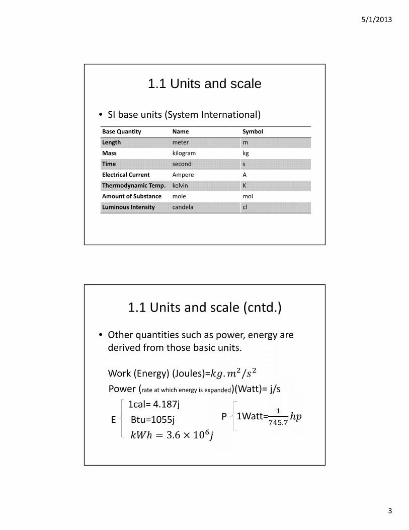
• SI base units (System International)Base Quantity Name Symbol
Length meter m
Mass kilogram kg
Time second s
Electrical Current Ampere A
Thermodynamic Temp. kelvin K
Amount of Substance mole mol
Luminous Intensity candela cl
1.1 Units and scale (cntd.)
• Other quantities such as power, energy arederived from those basic units.
Work (Energy) (Joules)= . /Power (rate at which energy is expanded)(Watt)= j/s
1cal= 4.187jE Btu=1055j= 3.6 × 10 P 1Watt= .
5/1/2013
4
1.1 Units and scale (cntd.)
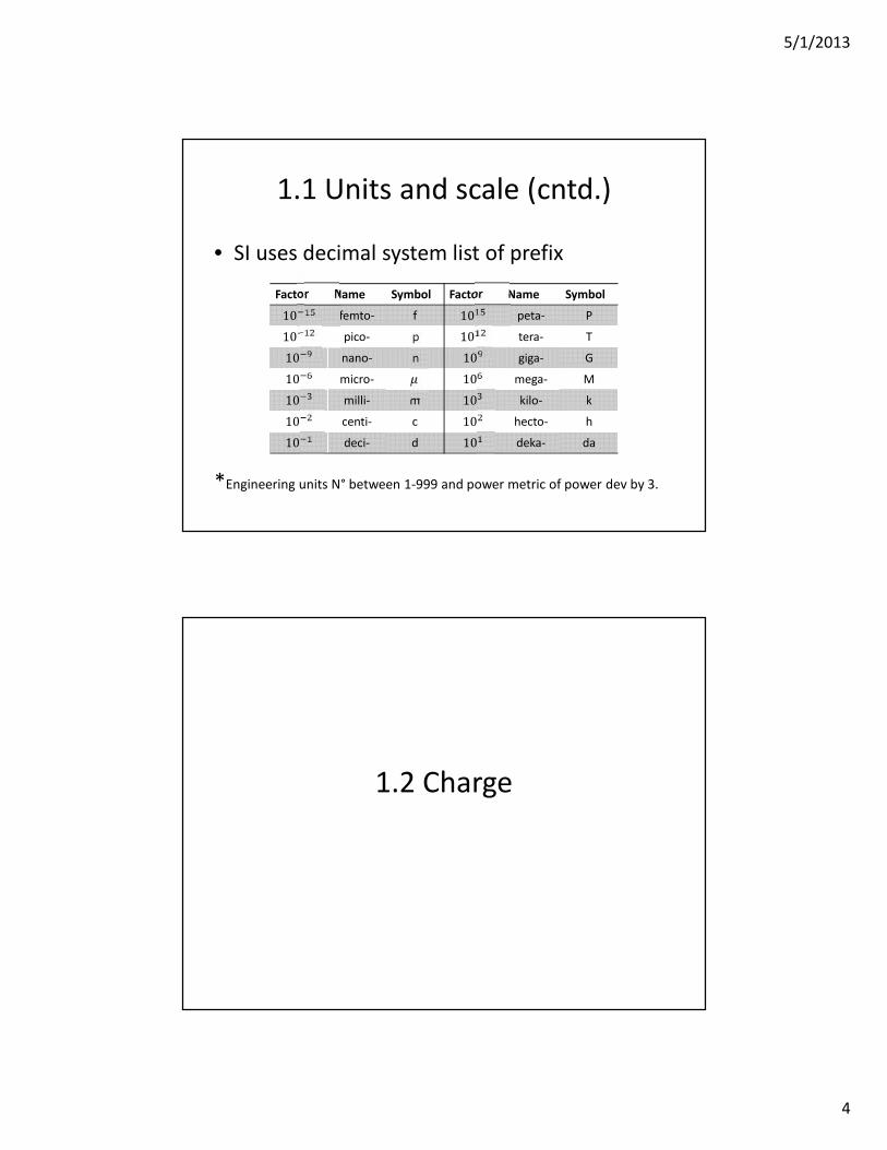
• SI uses decimal system list of prefix
*Engineering units N° between 1-999 and power metric of power dev by 3.
Factor Name Symbol Factor Name Symbol10 femto- f 10 peta- P10 pico- p 10 tera- T10 nano- n 10 giga- G10 micro- 10 mega- M10 milli- m 10 kilo- k10 centi- c 10 hecto- h10 deci- d 10 deka- da
1.2 Charge
5/1/2013
5
1.2 Charge• Electrical charge: “is a physical property of matter
that causes it to experience a force when nearother electrically charged matter”
• There are two types of charges; +ve (protons) and–ve (electrons).
• The charge symbol Q, q(t) and q.• The charge unit is coulomb (C).• A single electron has a charge of −1.6 × 10 .• The motion of charges “electrons” is what create
the electrical current.
1.3 Current
5/1/2013
6
1.3 Current• “Is a measure of the rate at which charge is moving past a given reference
point in a specified direction.” =• Current has both a numerical value and a direction.• Current in wire is actually due to –ve charge in motion, not the –ve charge
as stated.• Current unit is Ampere (A).
• Charge transferred between time & . ∫ = ∫ .( )( )hence, the total charge is = . +
1.3 Current (Cntd.)
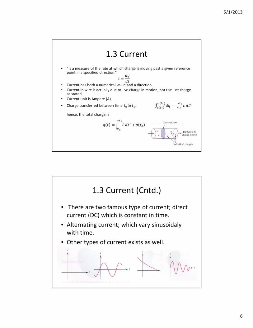
• There are two famous type of current; directcurrent (DC) which is constant in time.
• Alternating current; which vary sinusoidalywith time.
• Other types of current exists as well.
5/1/2013
7
1.3 Current (Cntd.)
• Current Direction: Although current flow inmetallic conductor results from electronmotion, it’s convenient to think of current asthe motion of +ve charges.
• Current arrows does not indicate the “actual”direction of current flow. It’s simply a part ofconvention.
10A -10A
1.4 Voltage
5/1/2013
8
1.4 Voltage
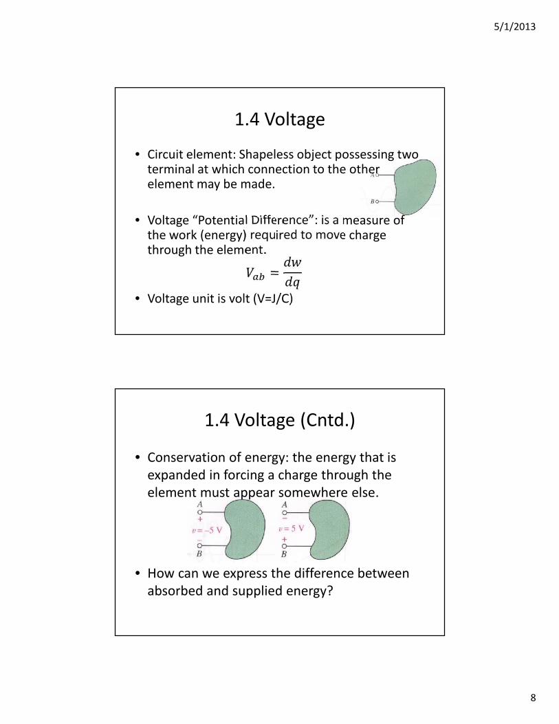
• Circuit element: Shapeless object possessing twoterminal at which connection to the otherelement may be made.
• Voltage “Potential Difference”: is a measure ofthe work (energy) required to move chargethrough the element.=
• Voltage unit is volt (V=J/C)
1.4 Voltage (Cntd.)
• Conservation of energy: the energy that isexpanded in forcing a charge through theelement must appear somewhere else.
• How can we express the difference betweenabsorbed and supplied energy?
5/1/2013
9
1.5 Power
1.5 Power
• “Is the rate at which energy is expanded”• Circuit element is one of two cases; either
power absorber or power supplier.• Note: the direction of the current with respect
to the voltage is what determine wetherpower is being absorbed or supplied.
• Power is denoted by P, p(t) or p.• The unit of power is watt.
5/1/2013
10
1.5 Power (cntd)
• Watt: “if one joule of energy is expanded intransferring one coulomb of charge through thedevice in one second. Then, the rate of energytransfer (power) is one watt”
• Hence from that definition we see that powermust be proportional to both the currententering the element and the voltage across it.Thus,
P=vij/c.c/s=j/s= watt
1.5 Power (cntd)
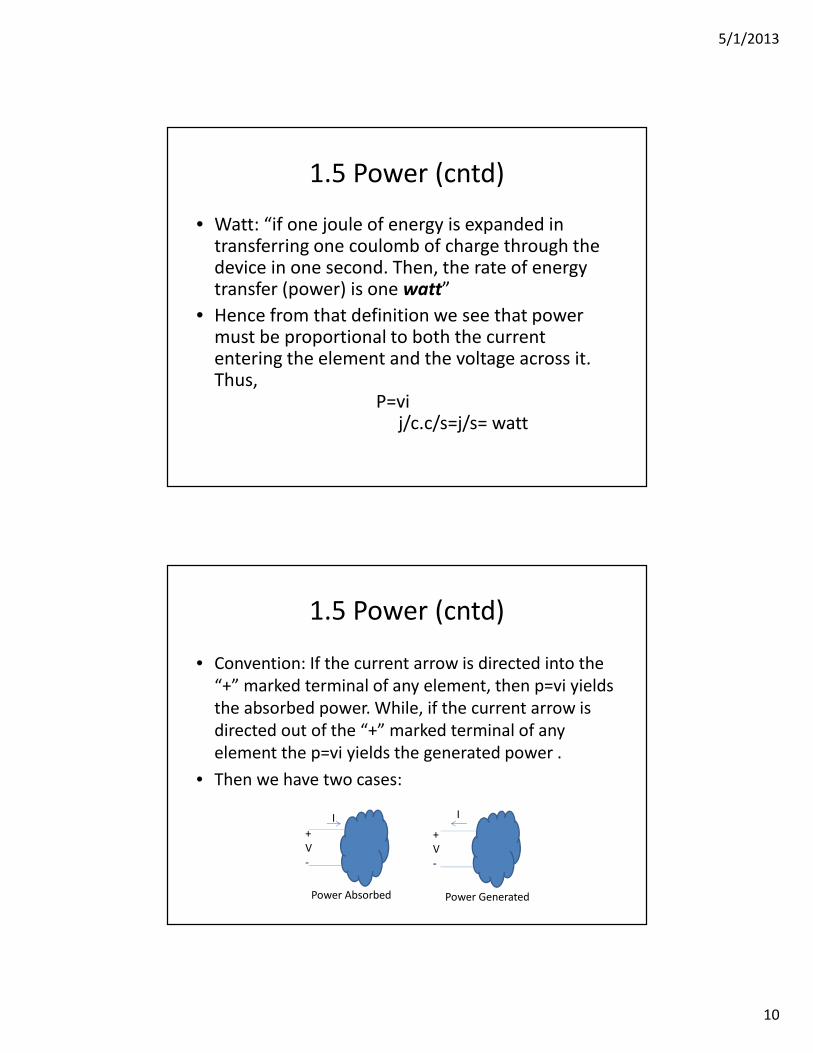
• Convention: If the current arrow is directed into the“+” marked terminal of any element, then p=vi yieldsthe absorbed power. While, if the current arrow isdirected out of the “+” marked terminal of anyelement the p=vi yields the generated power .
• Then we have two cases:
+V-
+V-
I I
Power Absorbed Power Generated
5/1/2013
11
1.6 Circuit Elements
1.6 Circuit Elements
• A simple circuit element “ is the mathematicalmodel of a two terminal electrical device”
• Circuit element can be characterized by itsvoltage current relationship.
• There is a difference between the physicaldevice and the mathematical model.
5/1/2013
12
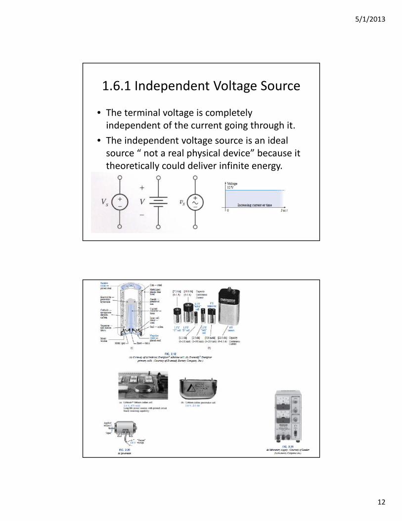
1.6.1 Independent Voltage Source
• The terminal voltage is completelyindependent of the current going through it.
• The independent voltage source is an idealsource “ not a real physical device” because ittheoretically could deliver infinite energy.
5/1/2013
13
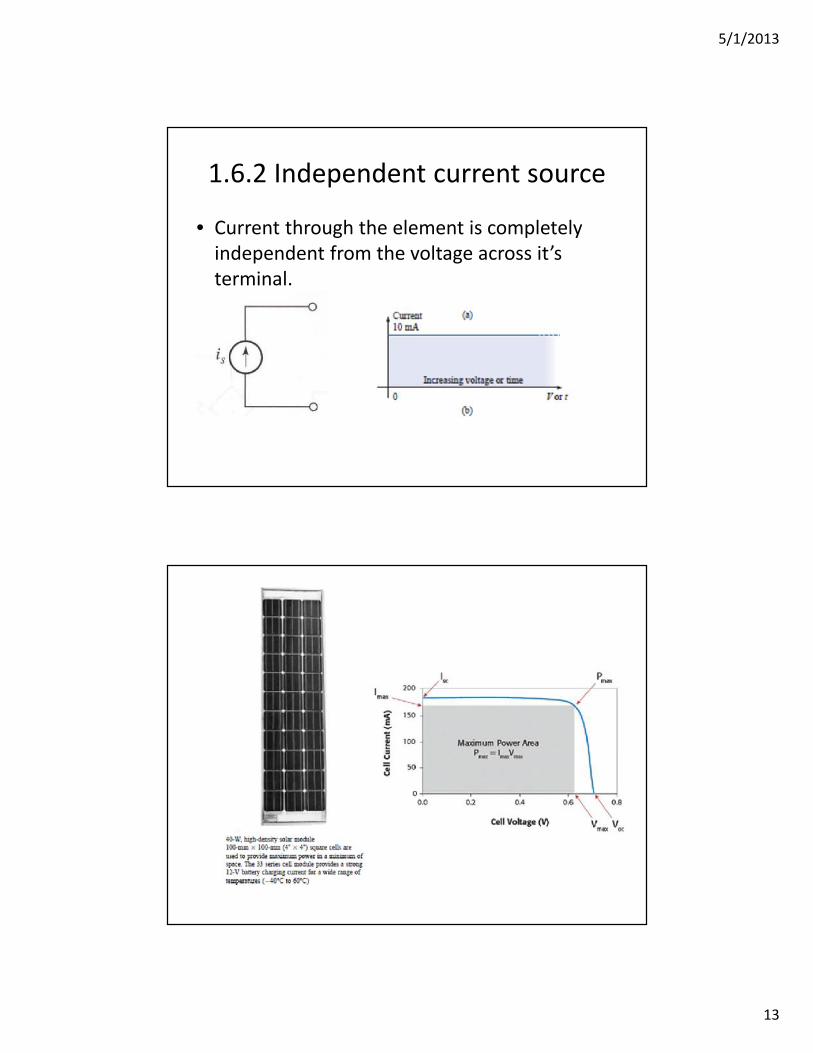
1.6.2 Independent current source
• Current through the element is completelyindependent from the voltage across it’sterminal.
5/1/2013
14
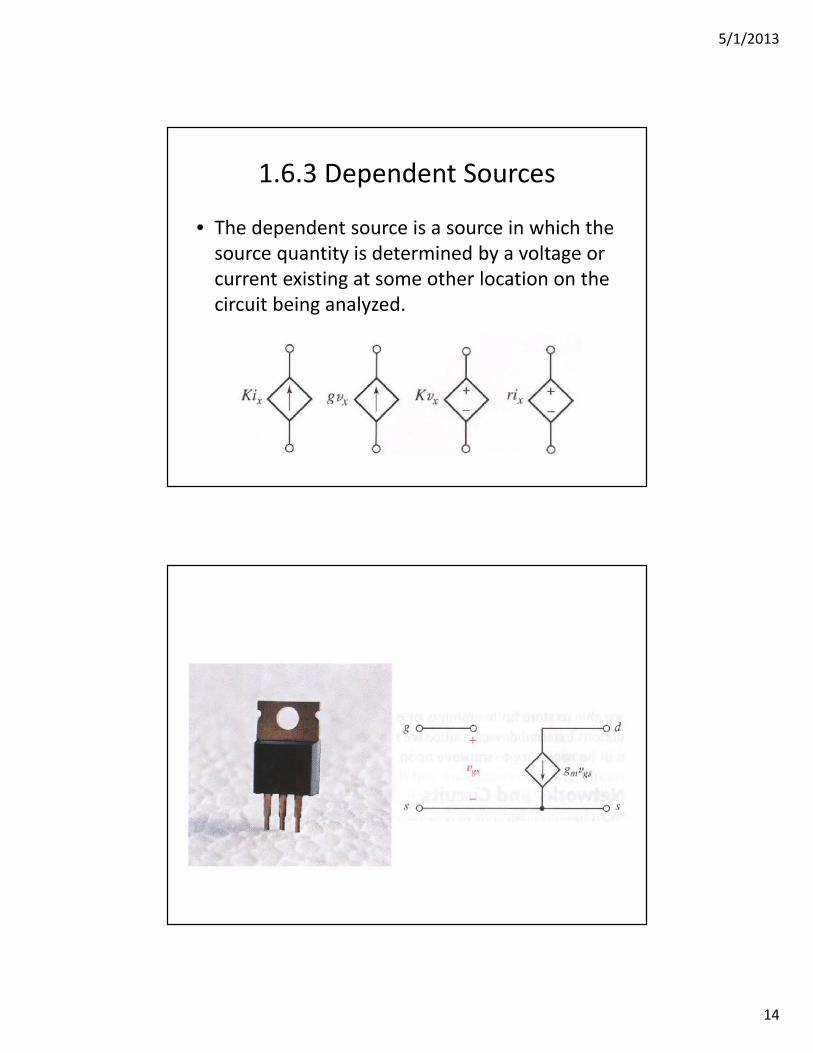
1.6.3 Dependent Sources
• The dependent source is a source in which thesource quantity is determined by a voltage orcurrent existing at some other location on thecircuit being analyzed.
5/1/2013
15
1.7 Network and circuits
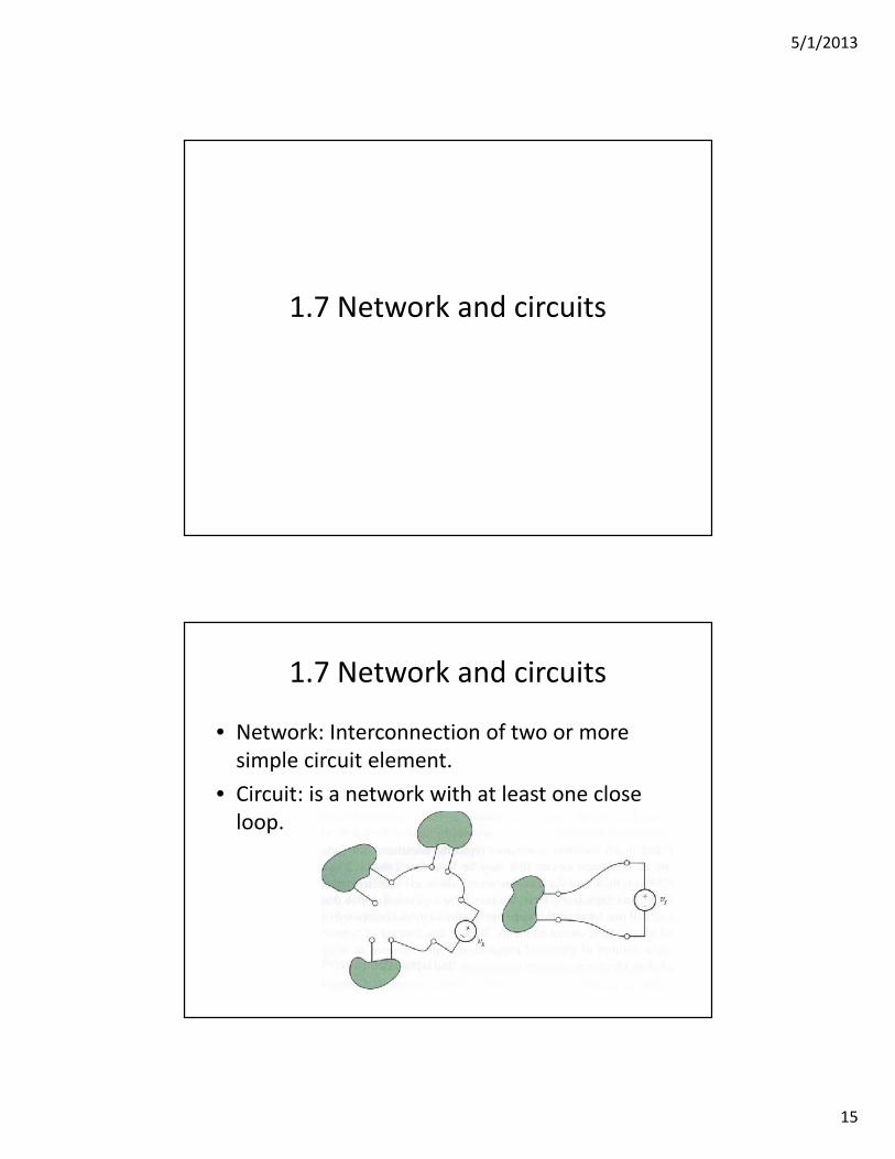
1.7 Network and circuits
• Network: Interconnection of two or moresimple circuit element.
• Circuit: is a network with at least one closeloop.
5/1/2013
16
1.8 Ohm’s law
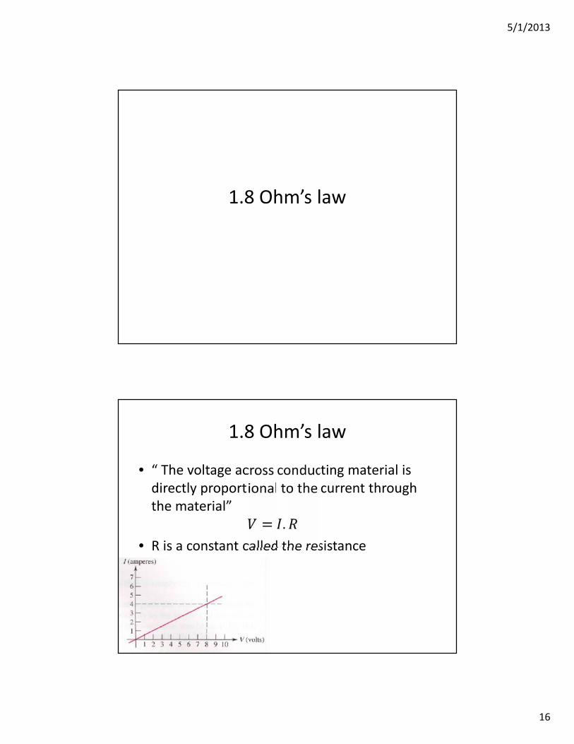
1.8 Ohm’s law
• “ The voltage across conducting material isdirectly proportional to the current throughthe material” = .
• R is a constant called the resistance
5/1/2013
17
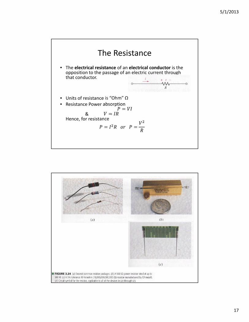
The Resistance• The electrical resistance of an electrical conductor is the
opposition to the passage of an electric current throughthat conductor.
• Units of resistance is “Ohm” Ω• Resistance Power absorption=
& =Hence, for resistance= =
5/1/2013
18
Very Important!!!
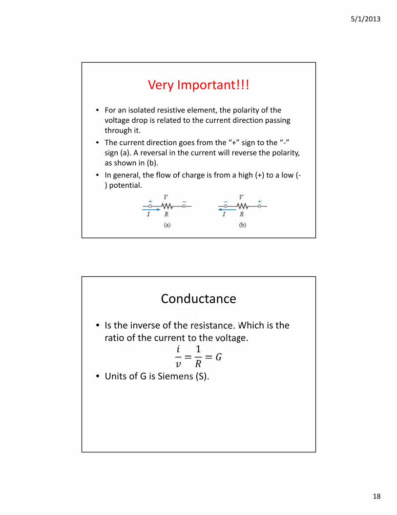
• For an isolated resistive element, the polarity of thevoltage drop is related to the current direction passingthrough it.
• The current direction goes from the “+” sign to the “-”sign (a). A reversal in the current will reverse the polarity,as shown in (b).
• In general, the flow of charge is from a high (+) to a low (-) potential.
Conductance
• Is the inverse of the resistance. Which is theratio of the current to the voltage.= 1 =
• Units of G is Siemens (S).