Embed Size (px)
Citation preview
TBCAS-2008-Jul-0054 1
Abstract—Magnetic stimulation of neural tissue is an
attractive technology because neural excitation may be affected without requiring implantation of electrodes. Pulsed discharge circuits are typically implemented for clinical magnetic stimulation systems. However, pulsed discharge systems can confound in vitro experimentation. As an alternative to pulsed discharge circuits, we present a circuit to deliver asymmetric current pulses for generation of the magnetic field. We scaled the system down using ferrite cores for the excitation coil. The scaled system allows observation using electrophysiological techniques and preparations not commonly used for investigation of magnetic stimulation. The design was refined using a comprehensive set of design equations. Circuit modeling and simulation demonstrate that the proposed system is effective for stimulating neural tissue with electric field gradients generated by time varying magnetic fields. System performance is verified through electrical test.
Index Terms—Magnetic stimulation, coil design, rate of closure, ferrite core, circuit design, transcranial magnetic stimulation, functional magnetic stimulation
I. INTRODUCTION
AGNETIC stimulation of neural tissue is an intriguing technology because stimulation may be affected without
direct contact to the tissue under study. As such, magnetic stimulation offers advantages in biocompatibility, bioresistance and operational biotoxicity in comparison to electrical stimulation. The stimulating coil may be sealed and isolated from the target tissue during magnetic stimulation. Since there is no metal-electrolyte interface, as is the case with electrodes used for electrical stimulation, issues of charge transfer, electrode surface modification and corrosion are mitigated. In addition, magnetic fields penetrate without being attenuated through non-conductive tissue because their
Manuscript received July11, 2008. This work was supported in part by the
National Science Foundation Biomimetic MicroElectronic Systems Research Center Agreement No. H31512, Amendment 6 and sponsorship from National Semiconductor, Santa Clara, CA.
Eric Basham is with the Electrical Engineering Department, University of California, Santa Cruz, Santa Cruz, CA 95064 USA (phone: 831-459-5766, e-mail: [email protected]).
Zhi Yang is with the Electrical Engineering Department, University of California, Santa Cruz, Santa Cruz, CA 95064 USA (e-mail: [email protected]).
Wentai Liu is with the Electrical Engineering Department, University of California, Santa Cruz, Santa Cruz, CA 95064 USA, and also with the National Chiao Tung University, 1001 University Road, Hsinchu, Taiwan 300, ROC (e-mail: [email protected]).
permeability at low frequencies (<50Khz) is near unity.
Magnetic stimulation may be used to stimulate neural tissue without requiring surgery to implant electrodes when applied externally. One of the most important applications of external excitation of neural tissue is transcranial magnetic stimulation (TMS). There is a wide array of literature on TMS brain mapping and neuromodulation. External magnetic stimulation has also been used as an alternative to functional electrical stimulation (FES) to mitigate incontinence [1], pain treatment [2], evaluate spinal function and as a diagnostic tool for evaluation of nerve damage [3]. Reviews of magnetic stimulation and TMS in particular are available in [4-9].
Magnetic stimulation of neural tissue is typically accomplished with air core coils (centimeters in diameter) remote from the site of stimulation (centimeters distant). Spatially varying electric fields are generated using a single damped sinusoidal current pulse [10]. The use of air core coils, the distance from the site of stimulation and the driver circuit topology compound to make the energy requirements for magnetic stimulation significant (i.e. in the range of Joules). Magnetic stimulation with traditional methods confounds in vitro experimentation as the area of effect is quite large and interferes with standard electrophysiology recording equipment. The resulting electromagnetic interference and mechanical constraints are especially evident in adherent cell electrophysiological studies. Typically, only large and long neural preparations (centimeters in length) can be used for experimentation.
While extensive magnetic stimulation modeling work has been presented [11-16], considerably less quantitative in vitro work has been performed [17, 18]. In vitro experiments are critical for characterizing the site of action, the structures stimulated, and the long term tissue histological effects of magnetic stimulation. A properly scaled system also facilitates the study of the histological effects of magnetic stimulation and aids the investigation of pulsed electromagnetic fields on nerve regrowth. These are both active areas of investigation [19-21]. In vitro studies can be particularly useful for studies of localized gene regulation and expression due to magnetic stimulation. An in vitro system allows for precise control and isolation of experimental variables.
While electrical fields from arrays of electrodes can approximate magnetic stimulation, in vitro systems can
Circuit and Coil Design for In Vitro Magnetic Neural Stimulation Systems
Eric Basham, Zhi Yang, and Wentai Liu
M
TBCAS-2008-Jul-0054 2
provide critical insight into complex, often contradictory results common in magnetic stimulation experiments. For example, in stimulation of one dimensional (patterned) neuronal cultures, cultures displayed similar morphology, electrical response and spontaneous activity but the response to magnetic stimulation was successful in only 22% of all cultures and 64% of similarly patterned cultures [22]. The authors posited the existence of “initiating neurons” with a lower magnetic stimulation threshold. In this article, the difficulty in aligning morphological features to coil activation areas is specifically mentioned. Small scale coils and flexible stimulation systems meet this need. Similar cases may be found in clinical experiments as well. In a recent clinical evaluation of repetitive TMS (rTMS), the key difference in efficacy was found to link closely with the manufacturer model (and thus the specific waveform) generating the biphasic pulse [23]. Modifying full scale magnetic stimulation systems in a clinical environment presents significant challenges to proof of concept experimentation. As an example, there is little data that covers co-stimulation (pairing electrical stimulus with magnetic stimulus) and paired pulse protocols. Rapidly reconfigurable in vitro systems can be invaluable for developing better predictive models, correlating effects of clinical experiments [24] and developing proof of concept systems.
Selective stimulation, recruitment studies and nerve impulse blocking experiments are excellent examples of the need for more flexible systems. For blocking experiments, the blocking pulse must last until the action potential has propagated from the site of initiation. In full scale systems with large coils it is challenging to create pulses of the necessary amplitude and duration, given the use of large coils and the distance between stimulation sites [25]. Selective stimulation is studied with the use of subthreshold hyperpolarizing and depolarizing pulses. Full scale magnetic stimulation systems cannot deliver variable amplitude pulses on the necessary timescales. This is especially the case when the pulse widths are of widely different durations as the pulse width in full scale magnetic stimulation systems is set by the capacitance bank and the coil inductance, as discussed in the next section. Due to the currents and voltages involved dynamic reconfiguration of the capacitor bank and coil inductance is problematic. Much can be learned in vitro before committing to building a full scale magnetic stimulation system.
We have reduced the scale of magnetic stimulating systems to address the need for flexible, in vitro, systems. Scaling was accomplished by using ferrite cores to reduce the area of stimulation, increase the magnetic flux through the area of interest and ultimately reduce the power required for stimulation. Miniaturization of the system permits the location of the neural tissue closer to the coil, mitigating the need for high power switching devices and further reducing the overall amount of energy required for stimulation. With this approach, smaller neural preparations, such as retinal sections, brain slices and short sections of homogenous nerve
fibers are available to the experimenter. The reduced energy requirements have the advantage that more flexible circuit topologies may be employed. The current amplifier presented is capable of delivering arbitrary current waveforms into a low resistance inductive load, the magnetic stimulation coil, while maintaining stability.
II. APPROACH To determine a baseline for the circuit requirements of an in
vitro magnetic stimulation system the passive cable model of axons is employed. The spatial rate of change of the electric field along the length of the axon, ∂Ex/∂x, has been shown to predict extracellular neural electrical stimulation (see review in [26]). An equivalent expression for magnetic stimulation is [14]
),(),(),(),(2
222 txV
ttxV
xtxV
xtxE
mmm
mx
m +∂
∂+
∂∂
−=∂
∂ τλλr
(1)
where the length and time constants of the neural membrane
(λm and τm, respectively) are defined as
λm =i
m
rr
and τm=cmrm (2)
where x is the distance along the axis of the nerve fiber when the nerve fiber is aligned to the x axis, Ex is the electric filed along the x axis, Vm is the transmembrane voltage defined as the voltage difference between the intracellular and extracellular fluid (Vm=Vintracellular-Vextracellualr), rm is membrane resistance times unit length (kΩ·cm axon length), ri is intracellular resistance (Ω·cm-1), cm is membrane capacitance per unit length (F·cm-1). Setting Vm to zero leads to the definition of the “activating function”, λ2·∂Ex/∂x, which is useful for determining the initial change in Vm.
The activating function allows estimation of stimulation based upon the membrane length constant and the spatially varying electric field [26]. There is some debate in the literature as to whether the activation function is more conveniently defined as ∂Ex/∂x or as λ2·∂Ex/∂x [27], but here we use activating function to refer to λ2·∂Ex/∂x, and define the spatially varying electric field as δEx/δx, that is, the rate of change of the electric field with respect to the x axis.
Magnetic generation of the activating function is accomplished by stimulating a coil with a time varying current (di/dt). The current in turn generates a time varying magnetic field, which then generates an electric field according to (3) [28]
R
lddtdiN
Edo
p
π
μ
4
)(r
r −= (3)
where pEd
ris the primary electric field, μo is the permeability
of free space, di/dt is the rate of change of the electric current,
TBCAS-2008-Jul-0054 3
Time Varying Current Source
Magnetic Field
Coil (ur, L)
Axon
Electric Field (dEx//dx)
Action Potential
z
di/dt
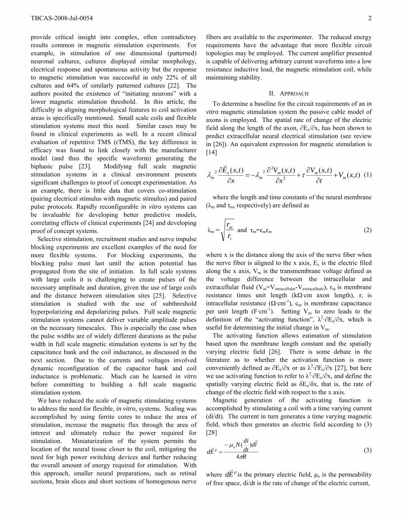
Fig. 1. Magnetic Stimulation System Diagram. B is magnetic field, ur is the coil relative permeability, di/dt is the current ramp, L is the coil inductance, h is the height above the coil. These terms represent the design variables for an in vitro magnetic stimulation system.
ldr
is an element of the coil, N is the number or turns and R is the distance between the coil element and the point where the electric field is calculated.
The spatial electric field also varies because the magnetic field is not uniform in space. Neural structures can be placed such that the activating function is at a maximum. A conceptual diagram is shown in Fig. 1.
The more linear the current ramp is the more uniform the electric field during the time course of the pulse since the induced electric field is a function of di/dt. In clinical functional magnetic stimulation experiments, a constant current ramp has been shown to have lower stimulation thresholds than the commonly used damped sinusoidal waveform [29]. Modeling of electrical stimulation pulse shape shows waveform shape impacts the strength-duration response, and thus the energy required for stimulation [30, 31]. Control over waveform shape also enables the evaluation of pulse shape mediated nerve recruitment [32, 33]. Clearly, the ability to test the effects of waveform shape on stimulation threshold is a necessary component of a quantitative magnetic stimulation system.
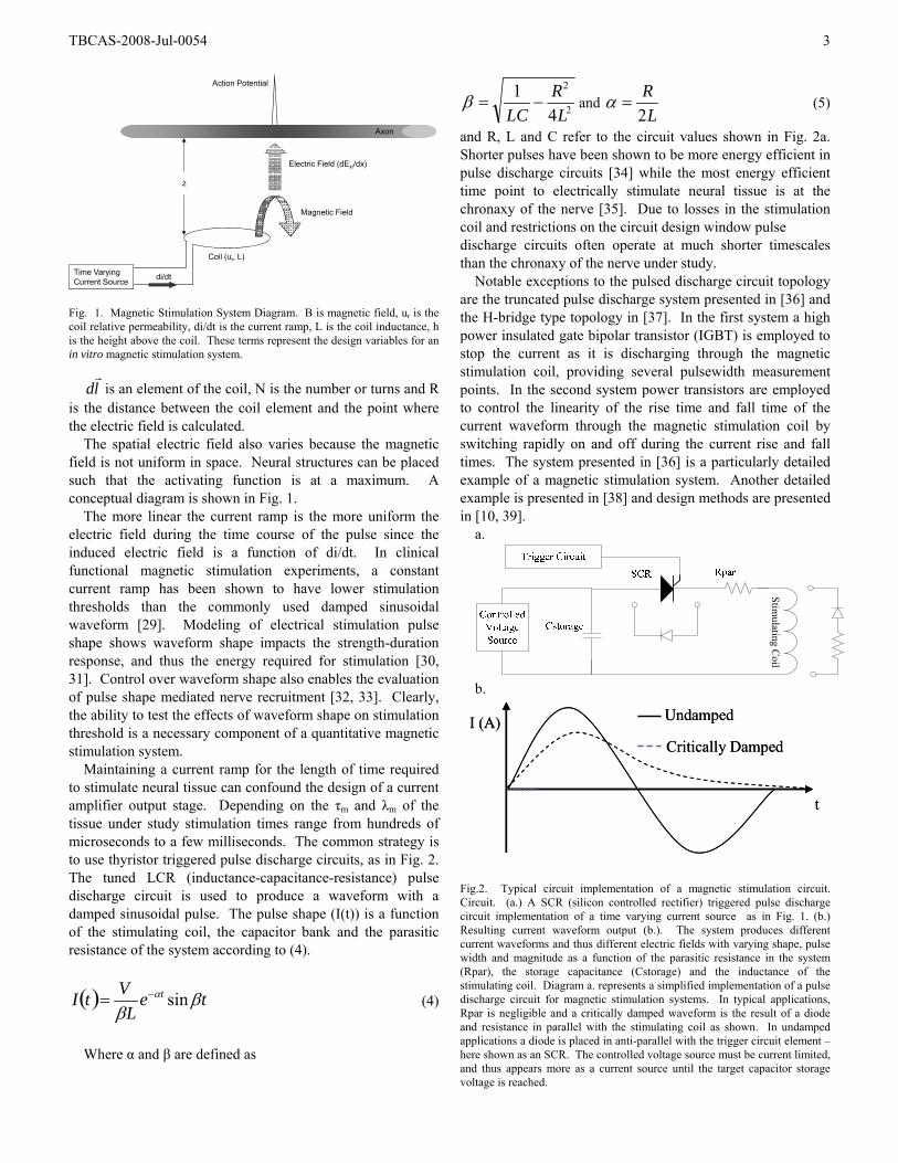
Maintaining a current ramp for the length of time required to stimulate neural tissue can confound the design of a current amplifier output stage. Depending on the τm and λm of the tissue under study stimulation times range from hundreds of microseconds to a few milliseconds. The common strategy is to use thyristor triggered pulse discharge circuits, as in Fig. 2. The tuned LCR (inductance-capacitance-resistance) pulse discharge circuit is used to produce a waveform with a damped sinusoidal pulse. The pulse shape (I(t)) is a function of the stimulating coil, the capacitor bank and the parasitic resistance of the system according to (4).
( ) teL
VtI t ββ
α sin−= (4)
Where α and β are defined as
2
2
41
LR
LC−=β and
LR
2=α (5)
and R, L and C refer to the circuit values shown in Fig. 2a. Shorter pulses have been shown to be more energy efficient in pulse discharge circuits [34] while the most energy efficient time point to electrically stimulate neural tissue is at the chronaxy of the nerve [35]. Due to losses in the stimulation coil and restrictions on the circuit design window pulse discharge circuits often operate at much shorter timescales than the chronaxy of the nerve under study.
Notable exceptions to the pulsed discharge circuit topology are the truncated pulse discharge system presented in [36] and the H-bridge type topology in [37]. In the first system a high power insulated gate bipolar transistor (IGBT) is employed to stop the current as it is discharging through the magnetic stimulation coil, providing several pulsewidth measurement points. In the second system power transistors are employed to control the linearity of the rise time and fall time of the current waveform through the magnetic stimulation coil by switching rapidly on and off during the current rise and fall times. The system presented in [36] is a particularly detailed example of a magnetic stimulation system. Another detailed example is presented in [38] and design methods are presented in [10, 39].
a.
Stimulating C
oil
b.
t
Critically Damped
UndampedI (A)
t
Critically Damped
UndampedI (A)
Fig.2. Typical circuit implementation of a magnetic stimulation circuit. Circuit. (a.) A SCR (silicon controlled rectifier) triggered pulse discharge circuit implementation of a time varying current source as in Fig. 1. (b.) Resulting current waveform output (b.). The system produces different current waveforms and thus different electric fields with varying shape, pulse width and magnitude as a function of the parasitic resistance in the system (Rpar), the storage capacitance (Cstorage) and the inductance of the stimulating coil. Diagram a. represents a simplified implementation of a pulse discharge circuit for magnetic stimulation systems. In typical applications, Rpar is negligible and a critically damped waveform is the result of a diode and resistance in parallel with the stimulating coil as shown. In undamped applications a diode is placed in anti-parallel with the trigger circuit element – here shown as an SCR. The controlled voltage source must be current limited, and thus appears more as a current source until the target capacitor storage voltage is reached.
TBCAS-2008-Jul-0054 4
t
Ex Peak (V)
I (A)
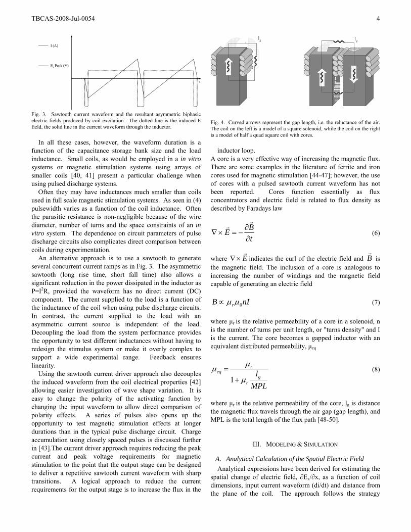
Fig. 3. Sawtooth current waveform and the resultant asymmetric biphasic electric fields produced by coil excitation. The dotted line is the induced E field, the solid line in the current waveform through the inductor.
In all these cases, however, the waveform duration is a function of the capacitance storage bank size and the load inductance. Small coils, as would be employed in a in vitro systems or magnetic stimulation systems using arrays of smaller coils [40, 41] present a particular challenge when using pulsed discharge systems.
Often they may have inductances much smaller than coils used in full scale magnetic stimulation systems. As seen in (4) pulsewidth varies as a function of the coil inductance. Often the parasitic resistance is non-negligible because of the wire diameter, number of turns and the space constraints of an in vitro system. The dependence on circuit parameters of pulse discharge circuits also complicates direct comparison between coils during experimentation.
An alternative approach is to use a sawtooth to generate several concurrent current ramps as in Fig. 3. The asymmetric sawtooth (long rise time, short fall time) also allows a significant reduction in the power dissipated in the inductor as P=I2R, provided the waveform has no direct current (DC) component. The current supplied to the load is a function of the inductance of the coil when using pulse discharge circuits. In contrast, the current supplied to the load with an asymmetric current source is independent of the load. Decoupling the load from the system performance provides the opportunity to test different inductances without having to redesign the stimulus system or make it overly complex to support a wide experimental range. Feedback ensures linearity.
Using the sawtooth current driver approach also decouples the induced waveform from the coil electrical properties [42] allowing easier investigation of wave shape variation. It is easy to change the polarity of the activating function by changing the input waveform to allow direct comparison of polarity effects. A series of pulses also opens up the opportunity to test magnetic stimulation effects at longer durations than in the typical pulse discharge circuit. Charge accumulation using closely spaced pulses is discussed further in [43].The current driver approach requires reducing the peak current and peak voltage requirements for magnetic stimulation to the point that the output stage can be designed to deliver a repetitive sawtooth current waveform with sharp transitions. A logical approach to reduce the current requirements for the output stage is to increase the flux in the
lg lg
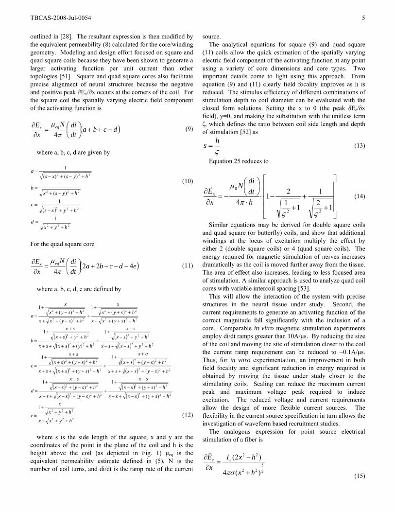
Fig. 4. Curved arrows represent the gap length, i.e. the reluctance of the air. The coil on the left is a model of a square solenoid, while the coil on the right is a model of half a quad square coil with cores.
inductor loop.
A core is a very effective way of increasing the magnetic flux. There are some examples in the literature of ferrite and iron cores used for magnetic stimulation [44-47]; however, the use of cores with a pulsed sawtooth current waveform has not been reported. Cores function essentially as flux concentrators and electric field is related to flux density as described by Faradays law
tBE
∂∂
−=×∇r
r (6)
where E
r×∇ indicates the curl of the electric field and B
r is
the magnetic field. The inclusion of a core is analogous to increasing the number of windings and the magnetic field capable of generating an electric field
nIB r 0μμ∝ (7)
where μr is the relative permeability of a core in a solenoid, n is the number of turns per unit length, or "turns density" and I is the current. The core becomes a gapped inductor with an equivalent distributed permeability, μeq
MPLlg
r
req
μ
μμ+
=1
(8)
where μr is the relative permeability of the core, lg is distance the magnetic flux travels through the air gap (gap length), and MPL is the total length of the flux path [48-50].
III. MODELING & SIMULATION
A. Analytical Calculation of the Spatial Electric Field Analytical expressions have been derived for estimating the
spatial change of electric field, ∂Ex/∂x, as a function of coil dimensions, input current waveform (di/dt) and distance from the plane of the coil. The approach follows the strategy
TBCAS-2008-Jul-0054 5
outlined in [28]. The resultant expression is then modified by the equivalent permeability (8) calculated for the core/winding geometry. Modeling and design effort focused on square and quad square coils because they have been shown to generate a larger activating function per unit current than other topologies [51]. Square and quad square cores also facilitate precise alignment of neural structures because the negative and positive peak ∂Ex/∂x occurs at the corners of the coil. For the square coil the spatially varying electric field component of the activating function is
( )dcbadtdiN
xE eqx −++⎟
⎠⎞
⎜⎝⎛=
∂∂
πμ4
(9)
where a, b, c, d are given by
( )
222
222
222
222
1
1)(
1)()(
1
hyxd
hyxsc
hysxb
hysxsa
++=
++−=
+−+=
+−+−=
(10)
For the quad square core
( )edcbadtdiN
xE eqx 422
4−−−+⎟
⎠⎞
⎜⎝⎛=
∂∂
πμ
(11)
where a, b, c, d, e are defined by
( )( )
( )( )
( )( )
( )
( )( )
( )( )
222
222
222
222
222
222
222
222
222
222
222
222
222
222
222
222
222
222
1
)(
)(1
)(
)(1
)(
)(1
)(
)()(1
1
)(
1
)(
)(1
)(
)(1
hyxx
hyx
x
e
hsysxsx
hsysx
sx
hsysxsx
hsysx
sx
d
hsysxsx
hsysx
ax
hsysxsx
hsysx
sx
c
hysxsx
hysx
sx
hysxsx
hysx
sx
b
hsyxx
hsyx
x
hsyxx
hsyx
x
a
+++
+++
=
+++−+−
+++−
−+
++−+−+−
+−+−
−+
=
+−++++
+−++
++
+++++++
++++
++
=
++−+−
++−
−+
++++++
+++
++
=
++++
++++
++−++
+−++
=
(12)
where s is the side length of the square, x and y are the
coordinates of the point in the plane of the coil and h is the height above the coil (as depicted in Fig. 1) μeq is the equivalent permeability estimate defined in (5), N is the number of coil turns, and di/dt is the ramp rate of the current
source. The analytical equations for square (9) and quad square
(11) coils allow the quick estimation of the spatially varying electric field component of the activating function at any point using a variety of core dimensions and core types. Two important details come to light using this approach. From equation (9) and (11) clearly field focality improves as h is reduced. The stimulus efficiency of different combinations of stimulation depth to coil diameter can be evaluated with the closed form solutions. Setting the x to 0 (the peak δEe/δx field), y=0, and making the substitution with the unitless term ζ, which defines the ratio between coil side length and depth of stimulation [52] as
ςhs = (13)
Equation 25 reduces to
⎥⎥⎥⎥
⎦
⎤
⎢⎢⎢⎢
⎣
⎡
++
+−⋅
⋅
⎟⎠⎞
⎜⎝⎛
−=∂
∂
121
1121
422
0
ςςπ
μ
hdtdiN
xEx
r
(14)
Similar equations may be derived for double square coils and quad square (or butterfly) coils, and show that additional windings at the locus of excitation multiply the effect by either 2 (double square coils) or 4 (quad square coils). The energy required for magnetic stimulation of nerves increases dramatically as the coil is moved further away from the tissue. The area of effect also increases, leading to less focused area of stimulation. A similar approach is used to analyze quad coil cores with variable intercoil spacing [53].
This will allow the interaction of the system with precise structures in the neural tissue under study. Second, the current requirements to generate an activating function of the correct magnitude fall significantly with the inclusion of a core. Comparable in vitro magnetic stimulation experiments employ di/dt ramps greater than 10A/μs. By reducing the size of the coil and moving the site of stimulation closer to the coil the current ramp requirement can be reduced to ~0.1A/μs. Thus, for in vitro experimentation, an improvement in both field focality and significant reduction in energy required is obtained by moving the tissue under study closer to the stimulating coils. Scaling can reduce the maximum current peak and maximum voltage peak required to induce excitation. The reduced voltage and current requirements allow the design of more flexible current sources. The flexibility in the current source specification in turn allows the investigation of waveform based recruitment studies.
The analogous expression for point source electrical stimulation of a fiber is
25
22
22
)(4
)2(
hx
hxIx
E ee
+
−=
∂∂
πσ
r
(15)
TBCAS-2008-Jul-0054 6
where eEr
is the electric field from the electrode, along the x axis, Ie is the electrode current and σ is the extracellular solution conductivity and h is the distance from the electrode to the nerve fiber. Observing the form of equation (14) and (15) it is seen that the spatial variation of the electric field during electric stimulation does not decrease in a similar manner to the spatial variation of the electric field generated by a magnetic field. In addition, very short pulses may exceed the charge density capabilities of microelectrodes and introduce additional variables into in vitro experiments. Electrical stimulation with passive cable modeling provides an analogy useful for control experiments, but subtleties in the distribution of field may prove significant, especially in the light that these are first order derivations useful for design insight.
To verify charge accumulation and define circuit design requirements, simulation was performed using a freely available active cable model simulation tool. Neurocal is a simplified package written in MATLAB that is very easy to use and modify [54]. Testing was performed using both using both unmyelinated nerve parameters from P. Clarkii [55, 56] and myelinated nerve parameters [57]. A typical result is shown in Fig. 5.
B. Circuit design A current ramp of ~0.1A/μs is well within the range of a power amplifier topology. It is critical that the rising edge of the waveform be as short as possible to prevent hyperpolarizing effects on the neural membrane, or worse inactivating the Na+ ion channels, increasing the energy requirements for stimulation. Typically a grounded load V-I converter, such as an improved Howland VCCS [58], would be used in this application. However, for a typical Howland current source as the signal frequency increases the output impedance falls [59].
Fig. 5. Typical simulation result using a pulsed electric field gradient to excite an axon fiber. 10 pulses, 50uS in duration, separated by 5uS deadtimes were applied (stim pulses). The action potential is seen to initiate at the site of the maximum electric field gradient after the 9th pulse (initiation site) and propagate along the axon in both directions from the site of initiation (propagation).
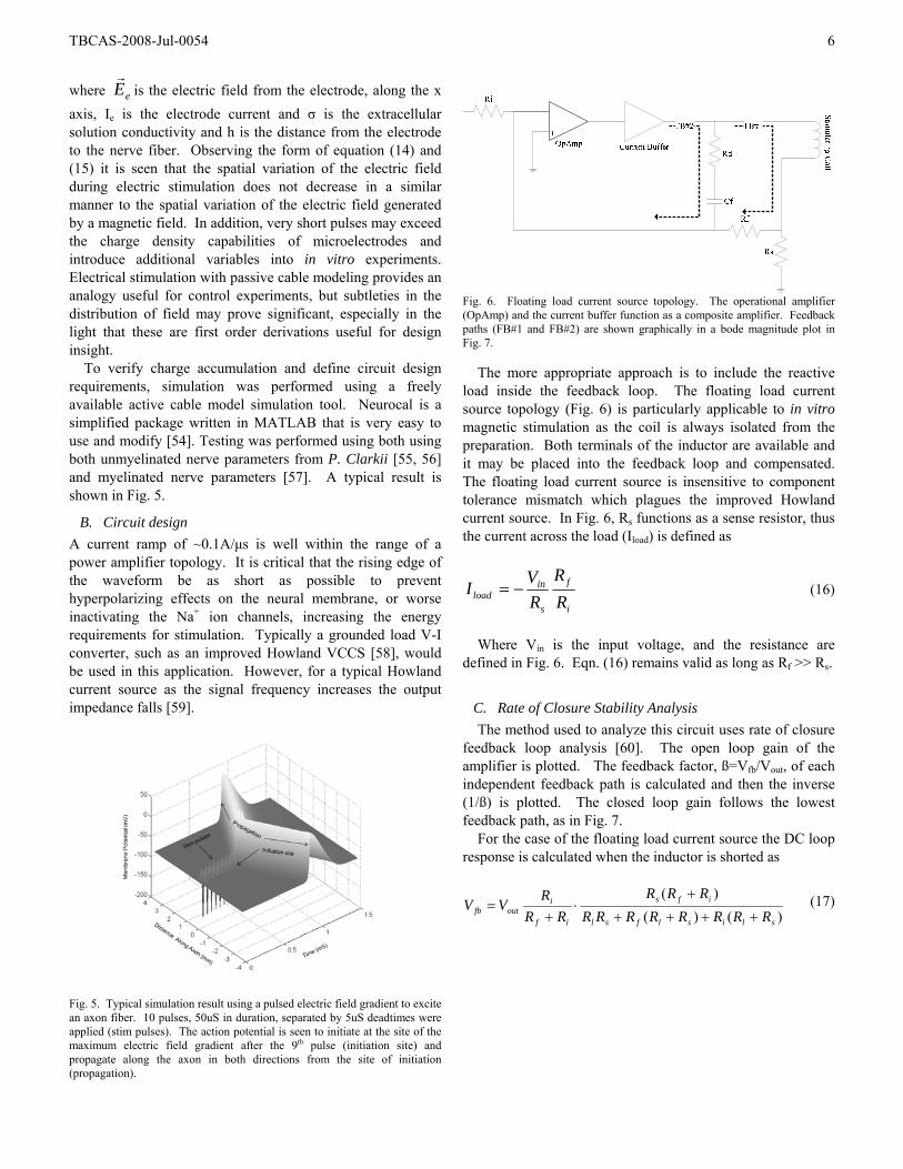
Fig. 6. Floating load current source topology. The operational amplifier (OpAmp) and the current buffer function as a composite amplifier. Feedback paths (FB#1 and FB#2) are shown graphically in a bode magnitude plot in Fig. 7.
The more appropriate approach is to include the reactive load inside the feedback loop. The floating load current source topology (Fig. 6) is particularly applicable to in vitro magnetic stimulation as the coil is always isolated from the preparation. Both terminals of the inductor are available and it may be placed into the feedback loop and compensated. The floating load current source is insensitive to component tolerance mismatch which plagues the improved Howland current source. In Fig. 6, Rs functions as a sense resistor, thus the current across the load (Iload) is defined as
i
f
s
inload R
RRVI −= (16)
Where Vin is the input voltage, and the resistance are
defined in Fig. 6. Eqn. (16) remains valid as long as Rf >> Rs.
C. Rate of Closure Stability Analysis The method used to analyze this circuit uses rate of closure
feedback loop analysis [60]. The open loop gain of the amplifier is plotted. The feedback factor, ß=Vfb/Vout, of each independent feedback path is calculated and then the inverse (1/ß) is plotted. The closed loop gain follows the lowest feedback path, as in Fig. 7.
For the case of the floating load current source the DC loop response is calculated when the inductor is shorted as
)()()(
slislfsl
ifs
if
ioutfb RRRRRRRR
RRRRR
RVV
++++
+⋅
+= (17)
TBCAS-2008-Jul-0054 7
Aol
Fz (L)
Gai
n (d
B)
Frequency (Log Hz)
FB#2
FB#11β
1βLoop gain
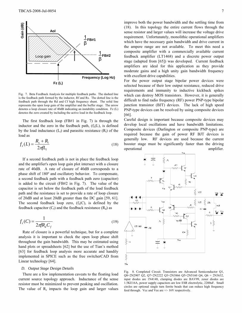
Fig. 7. Beta Feedback Analysis for multiple feedback paths. The dashed line is the feedback path formed by the inductor, Rf and Rs. The dotted line is the feedback path through the Rd and Cf high frequency shunt. The solid line represents the open loop gain of the amplifier and the buffer stage. The arrow denotes a loop closure rate of 40dB indicating an instability condition. Fz (L) denotes the zero created by including the active load in the feedback loop.
The first feedback loop (FB#1 in Fig. 7) is through the
inductor and the zero in the feedback path, (fz(L), is defined by the load inductance (Ll) and parasitic resistance (Rl) of the load as
l
lsz fL
RRLfπ2
)( += (18)
If a second feedback path is not in place the feedback loop
and the amplifier's open loop gain plot intersect with a closure rate of 40dB. A rate of closure of 40dB corresponds to a phase shift of 180º and oscillatory behavior. To compensate, a second feedback path with a feedback path zero (capacitor) is added to the circuit (FB#2 in Fig. 7). The value of the capacitor is set below the feedback path of the load feedback path and the resistance is set to provide a rate of loop closure of 20dB and at least 20dB greater than the DC gain [59, 61]. The second feedback loop zero, (fz(C), is defined by the feedback capacitor (Cf) and the feedback resistance (Rd) as
fdz CfR
Cfπ2
1)( = (19)
Rate of closure is a powerful technique, but for a complete analysis it is important to check the open loop phase shift throughout the gain bandwidth. This may be estimated using hand plots or spreadsheets [62] but the use of Tian’s method [63] for feedback loop analysis more accurate and handily implemented in SPICE such as the free switcherCAD from Linear technology [64].
D. Output Stage Design Details There are a few implementation caveats to the floating load
current source topology approach. Inductance of the sense resistor must be minimized to prevent peaking and oscillation. The value of Rs impacts the loop gain and larger values
improve both the power bandwidth and the settling time from (18). In this topology the entire current flows through the sense resistor and larger values will increase the voltage drive requirement. Unfortunately, monolithic operational amplifiers which have the necessary gain bandwidth and drive current in the ampere range are not available. To meet this need a composite amplifier with a commercially available current feedback amplifier (LT1468) and a discrete power output stage (adapted from [65]) was developed. Current feedback amplifiers are ideal for this application as they provide moderate gains and a high unity gain bandwidth frequency with excellent drive capabilities. For the power output stage bipolar power devices were selected because of their low output resistance, reduced drive requirements and immunity to inductive kickback spikes which can destroy MOS transistors. However, it is generally difficult to find radio frequency (RF) power PNP-type bipolar junction transistor (BJT) devices. The lack of high speed PNP-type devices can be resolved by using composite devices [66]. Careful design is important because composite devices may develop local oscillations and have bandwidth limitations. Composite devices (Darlington or composite PNP-type) are required because the gain of power RF BJT devices is generally low. RF devices are used because the current booster stage must be significantly faster than the driving operational amplifier.
Fig. 8. Completed Circuit. Transistors are Advanced Semiconductor Q1, Q8=2N2907 Q2, Q7=2N2222 Q3=2N3866 Q5=2N5160 Q4, Q6 = 2N3632, input diodes are 1N4148, clamping diodes are BAV99, zener diodes are 1.5KE16A, power supply capacitors are low ESR electrolytic, 2200uF. Small circles are optional single turn ferrite beads that can reduce high frequency feed through. Vcc and Vee are +/- 16V respectively.
TBCAS-2008-Jul-0054 8
The speed requirement of the current booster stage is easily understood by referring to Fig. 7. If the current booster stage has a 3db roll off below the unity gain bandwidth of the amplifier it will introduce and additional pole and invite oscillation. If the current feedback stage cannot respond to the output control signal from the amplifier then the output will oscillate while the current booster continually tries to catch up to the feedback signal measured at the sense resistor. To prevent the addition of poles in the feedback loop, the midband gain of the power stage must extend past the unity gain frequency of the amplifier [65, 67].
Placing a reactive load inside the feedback loop requires particular attention when switching currents. Switched currents result in sharp flyback pulses from the inductive load. Flyback voltage pulses can damage components and create intermittent failures. The most effective way to dissipate flyback voltage pulses is to include discrete ultrafast recovery flyback diodes (Fig. 8 clamping diodes shown on the right). With proper selection of components the parasitic capacitance added to the output is negligible. Additional protection from flyback pulses is achieved by using unidirectional zener diodes on the power supply rails [68].
IV. EXPERIMENTAL RESULTS
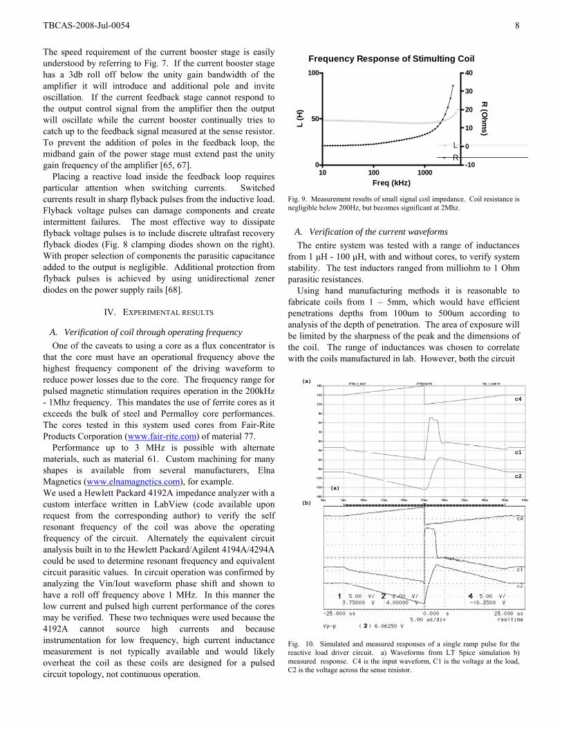
A. Verification of coil through operating frequency One of the caveats to using a core as a flux concentrator is
that the core must have an operational frequency above the highest frequency component of the driving waveform to reduce power losses due to the core. The frequency range for pulsed magnetic stimulation requires operation in the 200kHz - 1Mhz frequency. This mandates the use of ferrite cores as it exceeds the bulk of steel and Permalloy core performances. The cores tested in this system used cores from Fair-Rite Products Corporation (www.fair-rite.com) of material 77.
Performance up to 3 MHz is possible with alternate materials, such as material 61. Custom machining for many shapes is available from several manufacturers, Elna Magnetics (www.elnamagnetics.com), for example. We used a Hewlett Packard 4192A impedance analyzer with a custom interface written in LabView (code available upon request from the corresponding author) to verify the self resonant frequency of the coil was above the operating frequency of the circuit. Alternately the equivalent circuit analysis built in to the Hewlett Packard/Agilent 4194A/4294A could be used to determine resonant frequency and equivalent circuit parasitic values. In circuit operation was confirmed by analyzing the Vin/Iout waveform phase shift and shown to have a roll off frequency above 1 MHz. In this manner the low current and pulsed high current performance of the cores may be verified. These two techniques were used because the 4192A cannot source high currents and because instrumentation for low frequency, high current inductance measurement is not typically available and would likely overheat the coil as these coils are designed for a pulsed circuit topology, not continuous operation.
Frequency Response of Stimulting Coil
10 100 10000
50
100
-10
0
10
20
30
40
LR
Freq (kHz)
L (H
)
R (O
hms)
Fig. 9. Measurement results of small signal coil impedance. Coil resistance is negligible below 200Hz, but becomes significant at 2Mhz.
A. Verification of the current waveforms The entire system was tested with a range of inductances
from 1 μH - 100 μH, with and without cores, to verify system stability. The test inductors ranged from milliohm to 1 Ohm parasitic resistances.
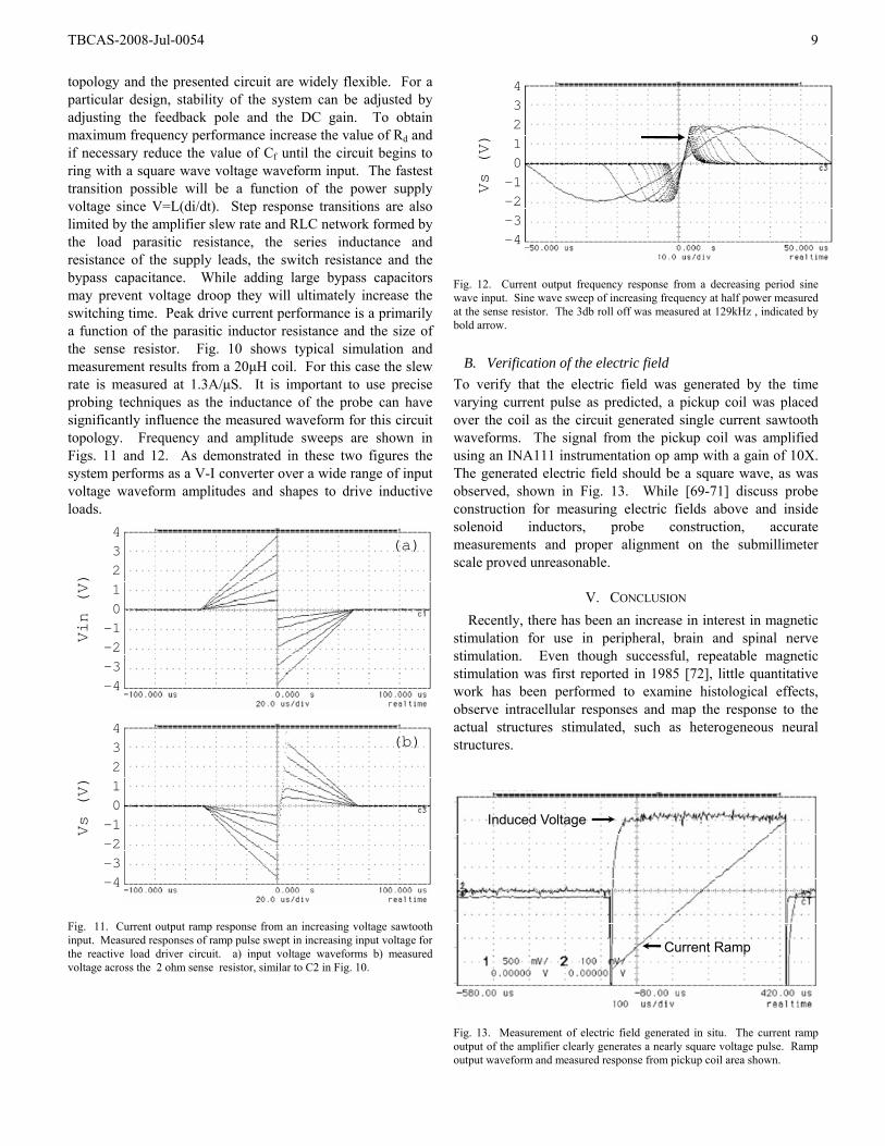
Using hand manufacturing methods it is reasonable to fabricate coils from 1 – 5mm, which would have efficient penetrations depths from 100um to 500um according to analysis of the depth of penetration. The area of exposure will be limited by the sharpness of the peak and the dimensions of the coil. The range of inductances was chosen to correlate with the coils manufactured in lab. However, both the circuit
c4
c1
c2
(a)
(a)
(b)
Fig. 10. Simulated and measured responses of a single ramp pulse for the reactive load driver circuit. a) Waveforms from LT Spice simulation b) measured response. C4 is the input waveform, C1 is the voltage at the load, C2 is the voltage across the sense resistor.
TBCAS-2008-Jul-0054 9
topology and the presented circuit are widely flexible. For a particular design, stability of the system can be adjusted by adjusting the feedback pole and the DC gain. To obtain maximum frequency performance increase the value of Rd and if necessary reduce the value of Cf until the circuit begins to ring with a square wave voltage waveform input. The fastest transition possible will be a function of the power supply voltage since V=L(di/dt). Step response transitions are also limited by the amplifier slew rate and RLC network formed by the load parasitic resistance, the series inductance and resistance of the supply leads, the switch resistance and the bypass capacitance. While adding large bypass capacitors may prevent voltage droop they will ultimately increase the switching time. Peak drive current performance is a primarily a function of the parasitic inductor resistance and the size of the sense resistor. Fig. 10 shows typical simulation and measurement results from a 20μH coil. For this case the slew rate is measured at 1.3A/μS. It is important to use precise probing techniques as the inductance of the probe can have significantly influence the measured waveform for this circuit topology. Frequency and amplitude sweeps are shown in Figs. 11 and 12. As demonstrated in these two figures the system performs as a V-I converter over a wide range of input voltage waveform amplitudes and shapes to drive inductive loads.
(a)
(b)
43210-1-2-3-4
43210-1-2-3-4
Vin (V)
Vs (V)
Fig. 11. Current output ramp response from an increasing voltage sawtooth input. Measured responses of ramp pulse swept in increasing input voltage for the reactive load driver circuit. a) input voltage waveforms b) measured voltage across the 2 ohm sense resistor, similar to C2 in Fig. 10.
43210-1-2-3-4
Vs (V)
Fig. 12. Current output frequency response from a decreasing period sine wave input. Sine wave sweep of increasing frequency at half power measured at the sense resistor. The 3db roll off was measured at 129kHz , indicated by bold arrow.
B. Verification of the electric field To verify that the electric field was generated by the time varying current pulse as predicted, a pickup coil was placed over the coil as the circuit generated single current sawtooth waveforms. The signal from the pickup coil was amplified using an INA111 instrumentation op amp with a gain of 10X. The generated electric field should be a square wave, as was observed, shown in Fig. 13. While [69-71] discuss probe construction for measuring electric fields above and inside solenoid inductors, probe construction, accurate measurements and proper alignment on the submillimeter scale proved unreasonable.
V. CONCLUSION Recently, there has been an increase in interest in magnetic
stimulation for use in peripheral, brain and spinal nerve stimulation. Even though successful, repeatable magnetic stimulation was first reported in 1985 [72], little quantitative work has been performed to examine histological effects, observe intracellular responses and map the response to the actual structures stimulated, such as heterogeneous neural structures.
Current Ramp
Induced Voltage
Fig. 13. Measurement of electric field generated in situ. The current ramp output of the amplifier clearly generates a nearly square voltage pulse. Ramp output waveform and measured response from pickup coil area shown.
TBCAS-2008-Jul-0054 10
With the development of the system presented, the opportunity to perform experiments with varying waveform, time sequencing and distribution presents itself.
The flexibility of arbitrary current waveform generation comes at a cost. Creating a full scale system based upon the linear current amplifier topology presented would be challenging and in all likelihood would require a modification of this approach. However, new power devices and pulse capacitors are continually under development [73-75] and supply the need for such devices in industrial applications. Switching strategies and circuit topologies can be tested in a smaller scale system before full power devices become commercially available.
While uniform nerve fibers were highlighted in this article, the proposed approach should also find utility in testing retina and dissociated cell in vitro cultures commonly used in microelectrode array experiments (MEA) concerning synapse formation and network analysis. The circuit approach may find utility in other applications such as magnetically based cell sorting [76]. Scaling also will prove useful for studying small intact structures such as brain slices and retina.
Simulation files, printed circuit board layout files, parts lists, sourcing recommendations and details of coil fabrication are available upon request by email to the authors ([email protected]).
VI. REFERENCES [1] N. Ishikawa, S. Suda, T. Sasaki, T. Yamanishi, H. Hosaka, K.
Yasuda, and H. Ito, "Development of a non-invasive treatment system for urinary incontinence using a functional continuous magnetic stimulator (FCMS)," Med Biol Eng Comput, vol. 36, pp. 704-10, 1998.
[2] J. Pujol, A. Pascual-Leone, C. Dolz, E. Delgado, J. L. Dolz, and J. Aldoma, "The effect of repetitive magnetic stimulation on localized musculoskeletal pain," Neuroreport, vol. 9, pp. 1745-1748, 1998.
[3] V. W. Lin and D. D. Cardenas, Spinal cord medicine : principles and practice. New York: Demos, 2003.
[4] A. T. Barker, "The history and basic principles of magnetic nerve stimulation," Electroencephalogr Clin Neurophysiol Suppl, vol. 51, pp. 3-21, 1999.
[5] P. J. Basser and B. J. Roth, "New Currents in Electrical Stimulation of Excitable Tissues," Annual Review of Biomedical Engineering, vol. 2, pp. 377-397, 2000.
[6] L. A. Geddes, "History of magnetic stimulation of the nervous system," J Clin Neurophysiol, vol. 8, pp. 3-9, 1991.
[7] M. Hallett, "Transcranial magnetic stimulation and the human brain," Nature, vol. 406, pp. 147-150, 2000.
[8] M. S. George, Z. Nahas, S. H. Lisanby, T. Schlaepfer, F. A. Kozel, and B. D. Greenberg, "Transcranial magnetic stimulation," Neurosurgery Clinics of North America, vol. 14, pp. 283-301, 2003.
[9] V. Walsh and A. Cowey, "Transcranial magnetic stimulation and cognitive neuroscience," J. Neurosci, vol. 19, pp. 5792-5801, 1999.
[10] A. Pascual-Leone, Handbook of transcranial magnetic stimulation. New York, NY: Arnold; Oxford University Press [distributor], 2002.
[11] H. A. C. Eaton, "The Electric Field Induced In A Spherical Volume Conductor By A Magnetic Coil," in Engineering in Medicine and Biology Society, 1990., Proceedings of the Twelfth Annual International Conference of the IEEE, 1990, pp. 2247-2248.
[12] M. Bencsik, R. Bowtell, and R. M. Bowley, "Electric fields induced in a spherical volume conductor by temporally varying magnetic field gradients," Physics in Medicine and Biology, pp. 557-576, 2002.
[13] P. Ravazzani, J. Ruohonen, F. Grandori, and G. Tognola, "Magnetic stimulation of the nervous system: Induced electric field in unbounded, semi-infinite, spherical, and cylindrical media," Annals of Biomedical Engineering, vol. 24, pp. 606-616, 1996.
[14] B. J. Roth and P. J. Basser, "A model of the stimulation of a nerve fiber by electromagnetic induction," Biomedical Engineering, IEEE Transactions on, vol. 37, pp. 588-597, 1990.
[15] P. C. Miranda, L. Correia, R. Salvador, and P. J. Basser, "Tissue heterogeneity as a mechanism for localized neural stimulation by applied electric fields," Physics in Medicine and Biology, vol. 52, pp. 5603-5617, 2007.
[16] H. Ye, M. Cotic, and P. L. Carlen, "Transmembrane potential induced in a spherical cell model under low-frequency magnetic stimulation," Journal of Neural Engineering, vol. 4, pp. 283-293, 2007.
[17] S. S. Nagarajan, D. M. Durand, and K. Hsuing-Hsu, "Mapping location of excitation during magnetic stimulation: Effects of coil position," Annals of Biomedical Engineering, vol. 25, pp. 112-125, 1997.
[18] A. Rotem and E. Moses, "Magnetic stimulation of curved nerves," Biomedical Engineering, IEEE Transactions on, vol. 53, pp. 414-420, 2006.
[19] M. Kato, Electromagnetics in biology. Tokyo: Springer, 2006. [20] R.-R. Ji, T. E. Schlaepfer, C. D. Aizenman, C. M. Epstein, D. Qiu,
J. C. Huang, and F. Rupp, "Repetitive transcranial magnetic stimulation activates specific regions in rat brain," Proceedings of the National Academy of Sciences of the United States of America, vol. 95, pp. 15635-15640, December 22, 1998 1998.
[21] G. N. Li and D. Hoffman-Kim, "Tissue-Engineered Platforms of Axon Guidance," Tissue Engineering Part B: Reviews, vol. 14, pp. 33-51, 2008.
[22] A. Rotem and E. Moses, "Magnetic Stimulation of One-Dimensional Neuronal Cultures," Biophysical Journal, 2008.
[23] E. Wasserman, C. M. Epstein, and U. Ziemann, The Oxford handbook of transcranial stimulation. Oxford ; New York: Oxford University Press, 2008.
[24] M. C. Ridding and J. C. Rothwell, "Is there a future for therapeutic use of transcranial magnetic stimulation?," Nat Rev Neurosci, vol. 8, pp. 559-567, 2007.
[25] B. J. Roth, "Mechanisms for electrical stimulation of excitable tissue," Crit Rev Biomed Eng, vol. 22, pp. 253 - 305, 1994.
[26] F. Rattay, "Analysis of models for extracellular fiber stimulation," Biomedical Engineering, IEEE Transactions on, vol. 36, pp. 676-682, 1989.
[27] B. J. Roth, "Mechanisms for electrical stimulation of excitable tissue," Crit Rev Biomed Eng, vol. 22, pp. 253-305, 1994.
[28] K. P. Esselle and M. A. Stuchly, "Neural stimulation with magnetic fields: analysis of induced electric fields," Biomedical Engineering, IEEE Transactions on, vol. 39, pp. 693-700, 1992.
[29] W. J. Havel, J. A. Nyenhuis, J. D. Bourland, K. S. Foster, L. A. Geddes, G. P. Graber, M. S. Waninger, and D. J. Schaefer, "Comparison of rectangular and damped sinusoidal dB/dt waveforms in magnetic stimulation," Magnetics, IEEE Transactions on, vol. 33, pp. 4269-4271, 1997.
[30] M. Sahin and Y. Tie, "Non-rectangular waveforms for neural stimulation with practical electrodes," Journal of Neural Engineering, p. 227, 2007.
[31] A. T. Barker, C. W. Garnham, and I. L. Freeston, "Magnetic nerve stimulation: the effect of waveform on efficiency, determination of neural membrane time constants and the measurement of stimulator output," Electroencephalogr Clin Neurophysiol Suppl, vol. 43, pp. 227-37, 1991.
[32] N. Accornero, G. Bini, G. L. Lenzi, and M. Manfredi, "Selective Activation of Peripheral-Nerve Fiber Groups of Different Diameter by Triangular Shaped Stimulus Pulses," Journal of Physiology-London, vol. 273, pp. 539-560, 1977.
[33] W. M. Grill, W. M. Grill, and J. T. Mortimer, "Stimulus waveforms for selective neural stimulation," Engineering in Medicine and Biology Magazine, IEEE, vol. 14, pp. 375-385, 1995.
TBCAS-2008-Jul-0054 11
[34] A. Alkhateeb and R. P. Gaumond, "Excitation of frog sciatic nerve using pulsed magnetic fields effect of waveform variations," in Engineering in Medicine and Biology Society, 1995., IEEE 17th Annual Conference, 1995, pp. 1119-1120 vol.2.
[35] L. A. Geddes, "Accuracy limitations of chronaxie values," Biomedical Engineering, IEEE Transactions on, vol. 51, pp. 176-181, Jan 2004.
[36] A. V. Peterchev, R. Jalinous, and S. H. Lisanby, "A Transcranial Magnetic Stimulator Inducing Near-Rectangular Pulses With Controllable Pulse Width (cTMS)," Biomedical Engineering, IEEE Transactions on, vol. 55, pp. 257-266, 2008.
[37] D. Perreault and S. Mogren, "Magnetic Stimulator Power and Control Circuit," USPTO, Ed. USA: R.B. CArr Engineering, Onc., 2003.
[38] D. Prutchi and M. Norris, Design and development of medical electronic instrumentation : a practical perspective of the design, construction, and test of medical devices. Hoboken, N.J.: Wiley-Interscience, 2005.
[39] K. Davey and M. Riehl, "Designing transcranial magnetic stimulation systems," Magnetics, IEEE Transactions on, vol. 41, pp. 1142-1148, 2005.
[40] B. H. Han, I. K. Chun, S. C. Lee, and S. Y. Lee, "Multichannel magnetic stimulation system design considering mutual couplings among the stimulation coils," Biomedical Engineering, IEEE Transactions on, vol. 51, pp. 812-817, 2004.
[41] J. Ruohonen and R. J. Ilmoniemi, "Focusing and targeting of magnetic brain stimulation using multiple coils," Medical and Biological Engineering and Computing, vol. 36, pp. 297-301, 1998.
[42] K. H. Hsu and D. M. Durand, "Prediction of neural excitation during magnetic stimulation usingpassive cable models," Biomedical Engineering, IEEE Transactions on, vol. 47, pp. 463-471, 2000.
[43] T. Kotnik, D. Miklavcic, and T. Slivnik, "Time course of transmembrane voltage induced by time-varying electric fields—a method for theoretical analysis and its application," Bioelectrochemistry and Bioenergetics, vol. 45, pp. 3-16, 1998.
[44] B. Han, S. Lee, J. Kim, and J. Yi, "Some technical aspects of magnetic stimulation coil design with the ferromagnetic effect," Medical and Biological Engineering and Computing, vol. 41, pp. 516-518, 2003.
[45] K. Davey and C. M. Epstein, "Magnetic stimulation coil and circuit design," Biomedical Engineering, IEEE Transactions on, vol. 47, pp. 1493-1499, Nov 2000.
[46] B. H. Han, S. Y. Lee, J. H. Kim, and J. H. Yi, "Some technical aspects of magnetic stimulation coil design with the ferromagnetic effect," Medical and Biological Engineering and Computing, vol. 41, pp. 516-518, 2003.
[47] K. Davey, L. Luo, and D. A. Ross, "Toward functional magnetic stimulation (FMS) theory and experiment," Biomedical Engineering, IEEE Transactions on, vol. 41, pp. 1024-1030, 1994.
[48] A. van den Bossche, Inductors and Transformers for Power Electronics: CRC Press, 2005.
[49] A. Van den Bossche, V. Valchev, and T. Filchev, "Improved approximation for fringing permeances in gapped inductors," in Industry Applications Conference, 2002. 37th IAS Annual Meeting. Conference Record of the, 2002, pp. 932-938 vol.2.
[50] C. W. T. McLyman, W. T. McLyman, and M. McLyman, Transformer and Inductor Design Handbook: CRC Press, 2004.
[51] K. P. Esselle and M. A. Stuchly, "Cylindrical tissue model for magnetic field stimulation of neurons: effects of coil geometry," Biomedical Engineering, IEEE Transactions on, vol. 42, pp. 934-941, 1995.
[52] A. Alkhateeb, "Excitation of Frog Sciatic Nerve Using Magnetic Induction," in Electrical Engineering. vol. PhD: Pennsylvania State University, 1997.
[53] J. D. Sommers and R. P. Gaumond, "Spacing analysis of a focal magnetic stimulating coil," 1997, pp. 42-43.
[54] L. Zeng, "An electrode array for reversing the recrutimnet order of peripheral nerve stimulation," in Biomedical Engineering. vol. PhD: Case Westerrn Reserve University, 2004.
[55] B. Mulloney, N. Tschuluun, and W. M. Hall, "Architectonics of crayfish ganglia," Microscopy Research and Technique, vol. 60, pp. 253-265, 2003.
[56] R. M. Glantz and T. Viancour, "Integrative properties of crayfish medial giant neuron: steady-state model," J Neurophysiol, vol. 50, pp. 1122-1142, November 1, 1983 1983.
[57] L. Zeng and M. D. Dominique, "Extracellular voltage profile for reversing the recruitment order of peripheral nerve stimulation: a simulation study," Journal of Neural Engineering, p. 202, 2004.
[58] S. Franco, Design with operational amplifiers and analog integrated circuits, 3rd ed. New York: McGraw-Hill, 2002.
[59] J. Steele and T. Green, "Tame those versatile current source circuits," Elec. Des, pp. 61–72, 1992.
[60] A. S. S. a. K. C. Smith, Microelectronic Circuits, Fourth Ed,. New York: Oxford University Press, , 1998.
[61] A. Microtechnology, "Application note 19." [62] A. Microtechnology, "Loop Stability with Reactive Loads," in
Application Note 38. [63] M. Tian, V. Visvanathan, J. Hantgan, and K. Kundert, "Striving for
small-signal stability," Circuits and Devices Magazine, IEEE, vol. 17, pp. 31-41, 2001.
[64] M. Engelhardt, "Simulationsprogramm LT_SPICE (SwitcherCAD III)."
[65] "Williams, Jim, “High Speed Amplifier Techniques,” Linear Technology Corporation, Application Note 47, 1991.."
[66] P. R. Gray, Analysis and design of analog integrated circuits, 4th ed. New York: Wiley, 2001.
[67] "Williams, Jim, “Power Gain Stages for Monolithic Amplifiers,” Linear Technology Corporation, Application Note 18, March 1986.."
[68] J. Steele, "Protect Those Expensive Power Op Amps," Electronic Design, Jan 31, 1991 1991.
[69] R. L. Stenzel, "A new probe for measuring small electric fields in plasmas," Review of Scientific Instruments, vol. 62, p. 130, 1991.
[70] P. M. Glover and R. Bowtell, "Measurement of electric fields due to time-varying magnetic field gradients using dipole probes," Physics in Medicine and Biology, vol. 52, pp. 5119-5130, 2007.
[71] L. E. E. Soonchil, L. E. E. Yongkwan, and Y. U. Insuk, "Electric Field in Solenoids," Jpn J Appl Phys, vol. 44, pp. 5244-5248, 2005.
[72] A. T. Barker, R. Jalinous, and I. L. Freeston, "Non-invasive magnetic stimulation of human motor cortex," Lancet, vol. 1, pp. 1106-7, 1985.
[73] B. Travis, "IGBTs and MOSFETs vie for applications," EDN, vol. 44, pp. 77-88, 1999.
[74] A. Burke, "Ultracapacitors: why, how, and where is the technology," Journal of Power Sources, vol. 91, pp. 37-50, 2000.
[75] K. M. Slenes, P. Winsor, T. Scholz, M. Hudis, T. P. L. Inc, and N. M. Albuquerque, "Pulse power capability of high energy density capacitors based on anew dielectric material," Magnetics, IEEE Transactions on, vol. 37, pp. 324-327, 2001.
[76] M. Frenea-Robin, H. Chetouani, N. Haddour, H. Rostaing, J. Laforet, and G. Reyne, "Contactless diamagnetic trapping of living cells onto a micromagnet array," in Engineering in Medicine and Biology Society, 2008. EMBS 2008. 30th Annual International Conference of the IEEE, 2008, pp. 3360-3363.
TBCAS-2008-Jul-0054 12
Eric Basham (S’04-09) received a B.S. degree in
biotechnology from Cook College, Rutgers, NJ (’97), a M.S.E.E. degree from San Jose State University (’06), and is currently an electrical engineering Ph.D. candidate at the University of California, Santa Cruz.
He has worked as a technician at Marigenetics and HP Labs and as summer research intern at Rutgers, Aclara and Intel. His research interests include transistor design for sensing applications, fundamental aspects of neural interfacing, field programmable analog arrays, and biologically inspired computing.
Zhi Yang was born on November 29, 1981, in the People's
Republic of China. He received the B.S degree in electrical engineering from Zhejiang University, China, 2004. Since 2005, he has been with the University of California at Santa Cruz, where he received the M.S. degree in electrical engineering at 2007. He is now working towards the Ph.D. degree. His research interests are mathematic modeling, analog circuit design, data analysis, and neuroprosthetic devices.
Wentai Liu (S’78–M’81–SM’93) received the B.S. degree
from National Chiao-Tung University, Taiwan, the M.S. degree from National Taiwan University, and the Ph.D. degree from the University of Michigan. In 1983, he joined North Carolina State University, Raleigh, where he held the Alcoa Chair Professorship in the Department of Electrical and Computer Engineering. Since 2003, he has been a Professor in the Electrical Engineering Department at the University of California at Santa Cruz, where he is Campus Director of the NSF Engineering Research Center on Biomimetic Microelectronic Systems. His research interests include visual prosthesis, implantable electronics, highspeed transceiver design (wired and wireless), molecular electronics, microelectronic sensors, timing/clock optimization, on-chip interconnects and computer vision/image processing. Since its early stages, he has been leading the engineering efforts of the retinal prosthesis to restore vision, finally leading to successful preliminary implant tests in blind patients. He has published more than 180 technical papers and is a co-author of Wave Pipelining: Theory and CMOS Implementation (Kluwer Academic, 1994) and Emerging Technologies: Designing Low Power Digital Systems (IEEE Press, 1996). Dr. Liu has received an IEEE Outstanding Paper Award, Alcoa Foundation’s Distinguished Engineering Research Award, and the Outstanding Alumnus Award from National Chiao-Tung University. He is a University System of Taiwan Master Lecturer and Chair Professor of National Chiao-Tung University.