Embed Size (px)
Citation preview
BeBeC-2018-D20
1
CIRA ACOUSTIC ANTENNA REAL-TIME FPGA BEAMFORMING ALGORITHM VALIDATION
Gianluca Diodati1, Alessio Netti2, Vincenzo Quaranta1 and Francesco Camastra3
1CIRA, Italian Aerospace Research Centre
Via Maiorise snc, 81043, Capua (CE), Italy
2Department of Computer Science and Engineering, University of Bologna
3Dipartimento di Scienze e Tecnologie, University of Naples Parthenope
ABSTRACT
In the program LOWNOISE, funded by the Italian Ministero dell’Istruzione,
dell’Università e della Ricerca (MIUR), the Italian Aerospace Research Centre (CIRA) was
in charge of developing an Acoustic Antennas System to detect and characterize cars
emitted environmental noise. A fundamental part of the Antennas System was the acoustic
beam-forming algorithm, implemented on FPGA platform to satisfy real-time constraints
and numerically tested to verify its feasibility.
In this paper, a test strategy for the numerical evaluation of beamforming algorithms is
presented. Characteristic microphone signals, representative of physical acoustic antenna
noise measurements, were defined and generated by using the Matlab Phased Array
toolbox. In the first part of the paper, test signal description used in the evaluation is shown.
In the second part, algorithm’s performance in terms of numerical accuracy, latency and
FPGA resource usage (from the hardware point of view) and main lobe amplitude and
Maximum Side-lobe Level (from the software point of view) are reported as outcomes of
the numerical test campaign performed. The algorithm shows good processing capabilities
and is able to efficiently attenuate interfering noise sources and to reject background noise.
The spatial accuracy is found as expected from theory.
1 INTRODUCTION
In recent times, an increasing interest on microphone phased arrays has appeared both in
technology and in literature. They are used for spatial filtering of acoustic signals coming from
one or more sources, and to track sources' movements by means of triangulation. A lot of
possible applications can be envisaged (from drone detection and tracking to environmental
7th Berlin Beamforming Conference 2018 Diodati, Netti, Quaranta and Camastra
2
noise measurements -aircraft take-off and landing, train and car pass-by noise-, etc).
Microphones phased arrays are passive systems (they can detect noise sources without emitting
any signal) and are cheaper with respect to traditional systems based on electromagnetic signals
(RADAR). They benefit of the improvements in the SmartPhone market, since they can utilize
the same MEMS microphones that are used in COTS SmartPhones.
Signals coming from the microphones can be processed in a variety of ways. Because of the
large amounts of data, processing such data in real-time is not trivial. Recent efforts have
focused on using hardware-programmable devices such as Field Programmable Gate Arrays
(FPGA), which are renowned for their parallelization potential, in order to attain real-time
throughput from data coming at high speed (high levels of bit quantization and sampling
frequency).
The system object of the present work has been developed inside the Italian Ministry of
Education, Universities and Research (MIUR) funded project LOWNOISE. The aim was to
build a system based on microphone phased arrays to be used in pass-by-noise tests to track an
auto vehicle and, contemporarily, characterize its environmental acoustic emission in real-time.
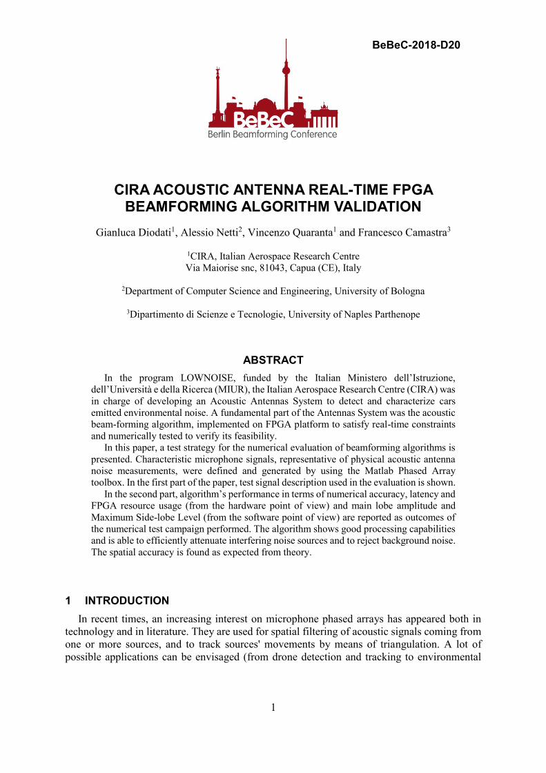
The microphone phased array was first designed by CIRA in [1] resulting in a system with 80
optimized randomly placed microphones, with acoustic signals quantized at 24 bit and sampled
at 96 kHz. The Beamforming algorithm was designed and FPGA-implemented by CIRA in
collaboration with the University of Naples Parthenope. Before manufacturing the overall
system, the beamformer was tested with synthesized signal in order to verify its features.
Fig. 1. Optimized random antenna designed by CIRA inside Low Noise project.
In the present work, we focus on numerically testing the hardware-implemented (FPGA-
implemented) real-time beamforming algorithm to verify that the expected performance is in-
line with that envisaged in the design phase. In the first two sections, a brief description of the
selected beamforming algorithm and its FPGA implementation are briefly recalled. Following
sections describe the numerical test strategy planned to verify the FPGA-implemented
beamforming algorithm and then the results of these tests. Tests results are briefly commented
in the Conclusions section.
7th Berlin Beamforming Conference 2018 Diodati, Netti, Quaranta and Camastra
3
2 REAL-TIME FPGA BEAMFORMING ALGORITHM
Beamforming is a technique to perform spatial filtering of signals (in the case of the present
paper, acoustic signals). This technique applies to signals acquired by means of an array of
sensors (microphone sensors in our case). A beamforming algorithm allows steering digitally
the sensor array in a particular direction in order to add coherently the acquired sensor signals
as they come from that direction. In this way, signals coming from the pointing direction are
reinforced, and the other coming from other directions are faded away. To perform the
calculation, an estimation of the time of arrivals of the signal from the pointing direction to the
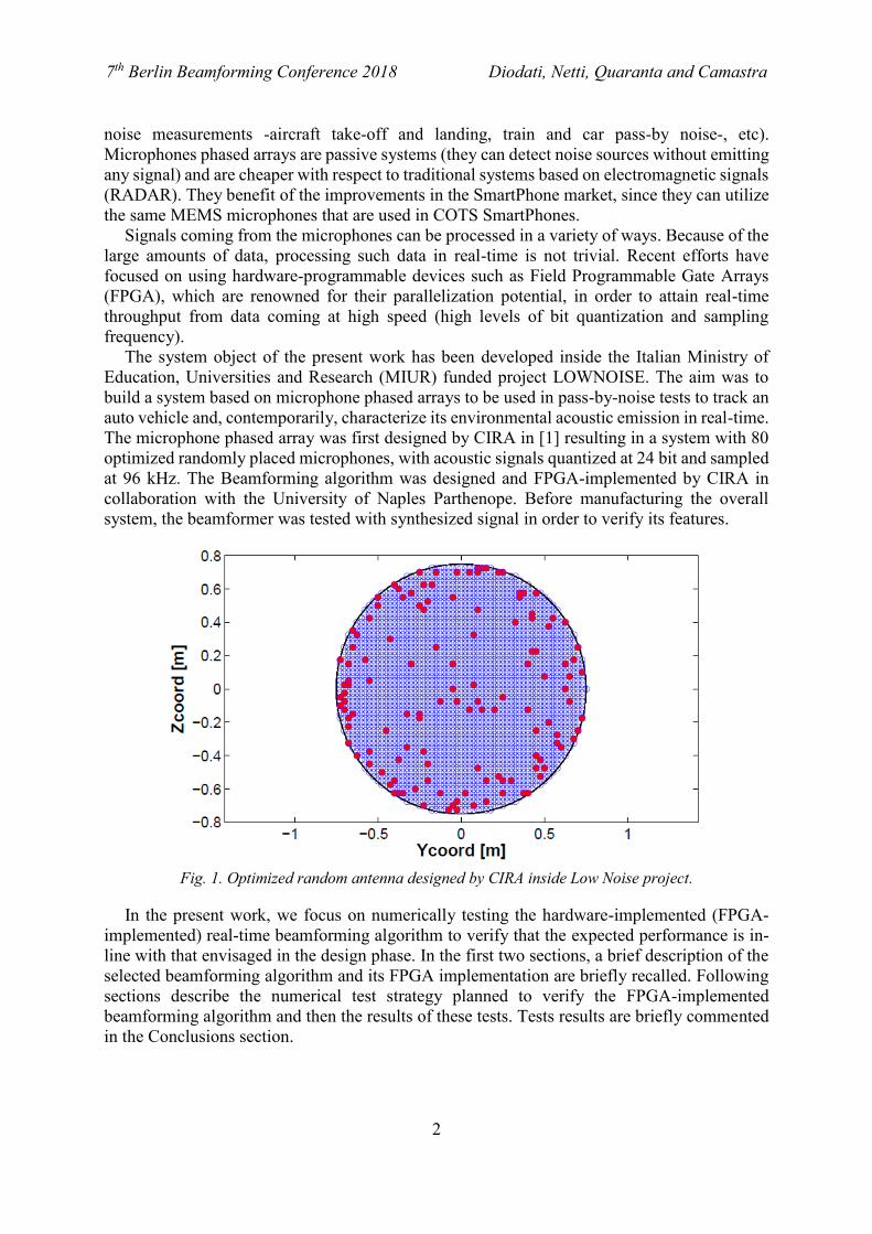
different sensors is necessary, as reported in the following picture
The beamforming algorithm implemented for the present work is a filter and sum Linearly
Constrained Minimum Variance (LCMV) Beamformer (see Fig. 2). Acoustic signals are first
filtered with a FIR filter with weights wi. They are then properly delayed (array steering) and
at last summed up. LCMV allows minimizing the harmful effects caused by noise, by
interfering sources, or by the low frequencies content of the acquired signal.
Fig. 2. Filter and Sum beamforming: signal acquisition, filtering, delay and sum stages.
The filters’ coefficients wi can be determined by means of:
The signal spatial covariance matrix Ry;
A constraint matrix 𝐶: the constraints allow imposing a null response from a certain
steering direction and symmetric coefficients for each of the filters (in order to result
in a Linear Phase beamformer);
A response vector 𝑐 such that C’w = c
A simple approximation of the covariance matrix is given by the following formula:
s
yyR
H
y (1)
Where y is a matrix with N columns, as many as the number of microphones of the array,
and s rows, as many as the number of samples for each acquired microphone signal. Using the
LCMV algorithm, the filter coefficients can be calculated with the following formula
7th Berlin Beamforming Conference 2018 Diodati, Netti, Quaranta and Camastra
4
cCRCCRw yy
11'1 (2)
The algorithm minimizes the power of the interfering signal (the background signal)
p = w′ Ry w subject to the constraint C′ w = c.
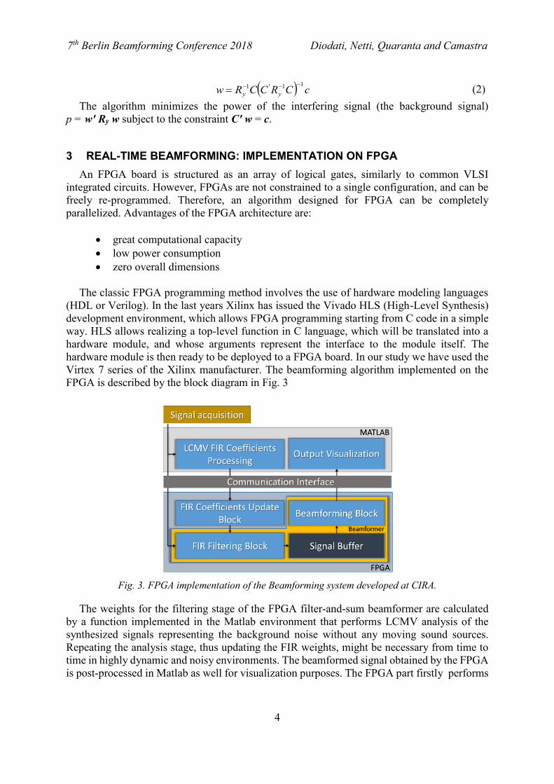
3 REAL-TIME BEAMFORMING: IMPLEMENTATION ON FPGA
An FPGA board is structured as an array of logical gates, similarly to common VLSI
integrated circuits. However, FPGAs are not constrained to a single configuration, and can be
freely re-programmed. Therefore, an algorithm designed for FPGA can be completely
parallelized. Advantages of the FPGA architecture are:
great computational capacity
low power consumption
zero overall dimensions
The classic FPGA programming method involves the use of hardware modeling languages
(HDL or Verilog). In the last years Xilinx has issued the Vivado HLS (High-Level Synthesis)
development environment, which allows FPGA programming starting from C code in a simple
way. HLS allows realizing a top-level function in C language, which will be translated into a
hardware module, and whose arguments represent the interface to the module itself. The
hardware module is then ready to be deployed to a FPGA board. In our study we have used the
Virtex 7 series of the Xilinx manufacturer. The beamforming algorithm implemented on the
FPGA is described by the block diagram in Fig. 3
Fig. 3. FPGA implementation of the Beamforming system developed at CIRA.
The weights for the filtering stage of the FPGA filter-and-sum beamformer are calculated
by a function implemented in the Matlab environment that performs LCMV analysis of the
synthesized signals representing the background noise without any moving sound sources.
Repeating the analysis stage, thus updating the FIR weights, might be necessary from time to
time in highly dynamic and noisy environments. The beamformed signal obtained by the FPGA
is post-processed in Matlab as well for visualization purposes. The FPGA part firstly performs
7th Berlin Beamforming Conference 2018 Diodati, Netti, Quaranta and Camastra
5
filtering of the 80 microphone signals, then stores the filtered signals in a buffer in order to
reduce the computational time of the FPGA (increasing throughput). Finally, the signals are
delayed and summed to obtain the beamformed signal for the different pointing directions
(specifically, the “sound power” coming from the pointing directions). In [7] we discuss how
our algorithm works in further detail.
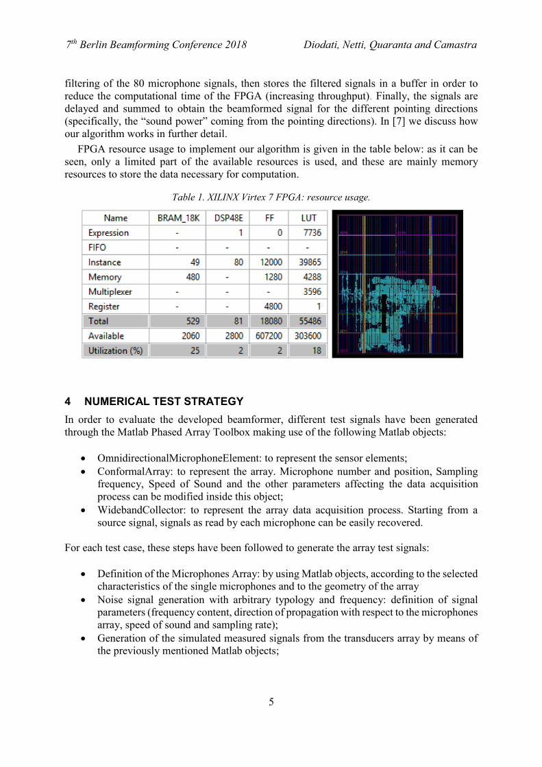
FPGA resource usage to implement our algorithm is given in the table below: as it can be
seen, only a limited part of the available resources is used, and these are mainly memory
resources to store the data necessary for computation.
Table 1. XILINX Virtex 7 FPGA: resource usage.
4 NUMERICAL TEST STRATEGY
In order to evaluate the developed beamformer, different test signals have been generated
through the Matlab Phased Array Toolbox making use of the following Matlab objects:
OmnidirectionalMicrophoneElement: to represent the sensor elements;
ConformalArray: to represent the array. Microphone number and position, Sampling
frequency, Speed of Sound and the other parameters affecting the data acquisition
process can be modified inside this object;
WidebandCollector: to represent the array data acquisition process. Starting from a
source signal, signals as read by each microphone can be easily recovered.
For each test case, these steps have been followed to generate the array test signals:
Definition of the Microphones Array: by using Matlab objects, according to the selected
characteristics of the single microphones and to the geometry of the array
Noise signal generation with arbitrary typology and frequency: definition of signal
parameters (frequency content, direction of propagation with respect to the microphones
array, speed of sound and sampling rate);
Generation of the simulated measured signals from the transducers array by means of
the previously mentioned Matlab objects;
7th Berlin Beamforming Conference 2018 Diodati, Netti, Quaranta and Camastra
6
Gaussian and interference noise (if required) is added to the signals, with its amplitude
depending on the sampled signal (the noise added is different for each microphone);
Signal conversion in 24-bit PCM format and scaling to use entire quantization range;
Signal sending and elaboration to the Beamforming FPGA module by means of suitably
formatted packets;
Processing and reading of the acoustic map;
Scaling (respect to the square of the input scale factor) to get the original power values;
Displaying the generated acoustic map.
A total of 160 test cases have been analyzed to test the hardware-implemented beamforming
algorithm. Each test case differs for the following parameters, characterizing the test scenarios:
Type of signal: Sine signals with several frequency (500, 1250, 2000Hz) and Chirp
signals (sweep from 500 to 2000 Hz);
Added noise amplitude: 5, 25, 50, 75 e 100% with respect to the signal amplitude;
Noise interference present or not, at the same frequency of the clean signal and at 50%
of its power, coming from different directions;
Propagation direction coincident or not with a pixel of the acoustic map;
Double-precision floating-point or fixed-point numeric types (to evaluate the
performance of FPGA implementation -that natively uses fixed-point arithmetic- with
respect to CPU implementation, which makes use of floating point arithmetic-).
5 NUMERICAL TEST CAMPAIGN & RESULTS
In the following paragraphs, the test campaign results are presented to compare the effect of the
various parameters affecting the beamformer’s performance:
5.1 Fixed-point vs Floating-point arithmetic effect
The first result we present is the difference in accuracy of fixed-point arithmetic against
floating-point, in Table 2. In fact, floating-point arithmetic is often not suitable for use in FPGA
algorithms, because of the latency and resources required in order to perform floating-point
operations.
Table 2. Acoustic map max error: Fixed-point vs Floating-point arithmetic.
Error type Mean Error
[dB or %] Std Error
[dB or %]
Absolute (500Hz - 1250Hz - 2000Hz) 0.023 0.089
Relative (500Hz - 1250Hz - 2000Hz) 0.001 0.009
Absolute (500Hz) 0.008 0.031
Relative (500Hz) 0.001 0.015
Absolute (1250Hz) 0.024 0.096
Relative (1250Hz) 0.001 0.005
Absolute (2000Hz) 0.037 0.139
Relative (2000Hz) 0.002 0.007
7th Berlin Beamforming Conference 2018 Diodati, Netti, Quaranta and Camastra
7
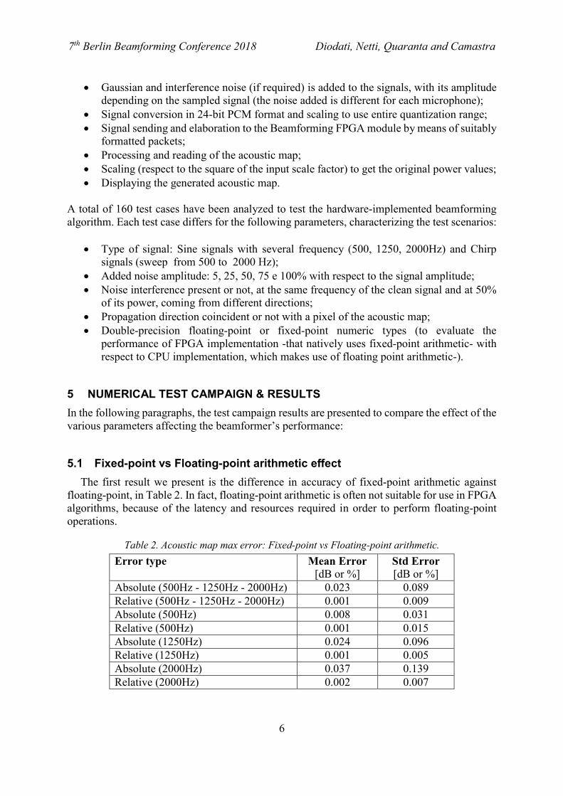
Fig. 4. Fixed-point vs Floating-point acoustic maps.
The differences in accuracy using the fixed-point arithmetic with 24 bits of quantization are
negligible with respect to using floating-point arithmetic, and they do not result in meaningfully
different acoustic maps.
5.2 Source signal frequency content effect
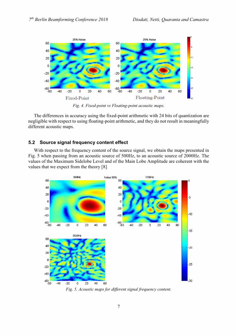
With respect to the frequency content of the source signal, we obtain the maps presented in
Fig. 5 when passing from an acoustic source of 500Hz, to an acoustic source of 2000Hz. The
values of the Maximum Sidelobe Level and of the Main Lobe Amplitude are coherent with the
values that we expect from the theory [8].
Fig. 5. Acoustic maps for different signal frequency content.
7th Berlin Beamforming Conference 2018 Diodati, Netti, Quaranta and Camastra
8
Table 3. FPGA Beamformer main characteristics vs signal frequency content.
MSL
Maximum Sidelobe Level
[dB]
Main Lobe Amplitude
[°]
500Hz -10 26
1250Hz -8.2 10.3
2000Hz -8.1 6
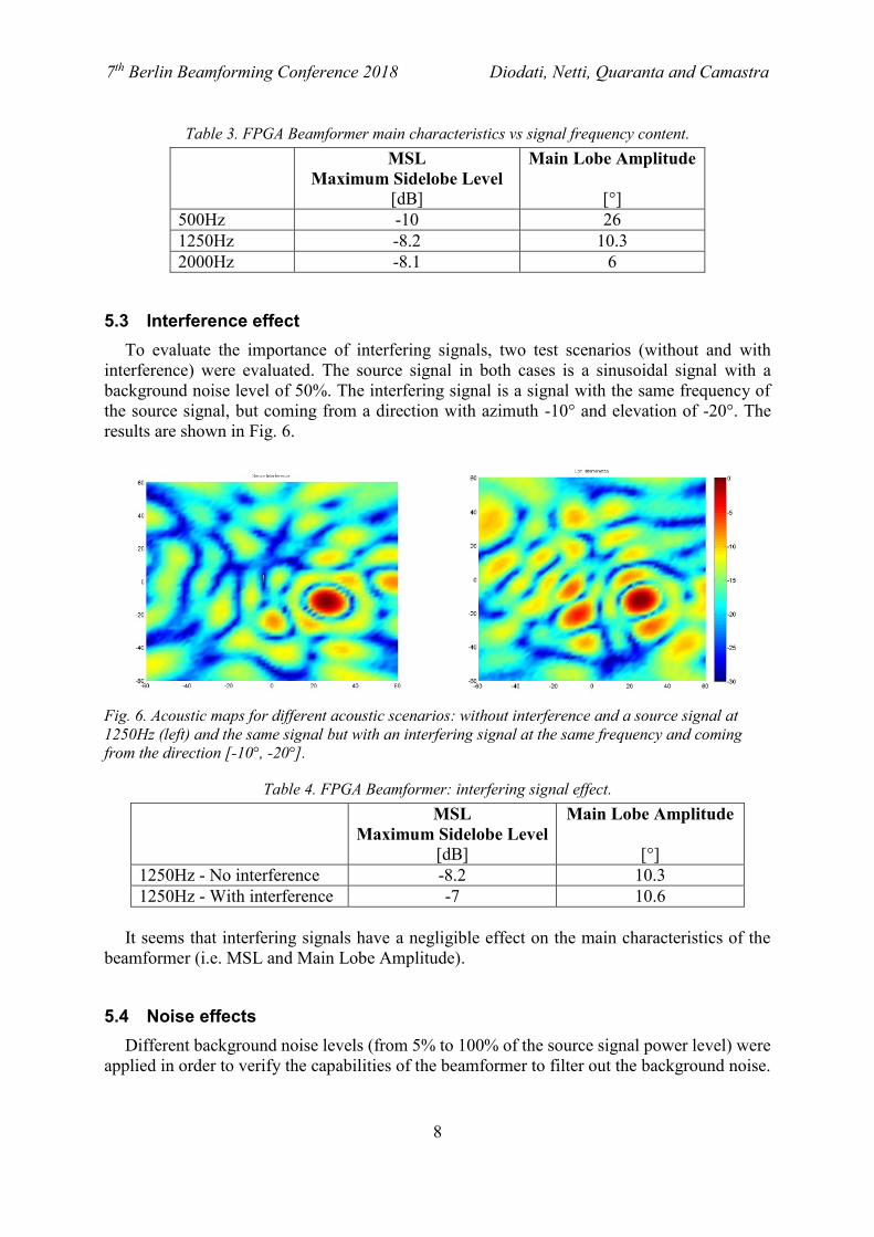
5.3 Interference effect
To evaluate the importance of interfering signals, two test scenarios (without and with
interference) were evaluated. The source signal in both cases is a sinusoidal signal with a
background noise level of 50%. The interfering signal is a signal with the same frequency of
the source signal, but coming from a direction with azimuth -10° and elevation of -20°. The
results are shown in Fig. 6.
Fig. 6. Acoustic maps for different acoustic scenarios: without interference and a source signal at
1250Hz (left) and the same signal but with an interfering signal at the same frequency and coming
from the direction [-10°, -20°].
Table 4. FPGA Beamformer: interfering signal effect.
MSL
Maximum Sidelobe Level
[dB]
Main Lobe Amplitude
[°]
1250Hz - No interference -8.2 10.3
1250Hz - With interference -7 10.6
It seems that interfering signals have a negligible effect on the main characteristics of the
beamformer (i.e. MSL and Main Lobe Amplitude).
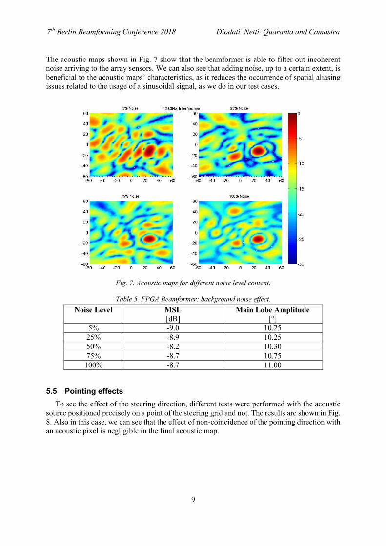
5.4 Noise effects
Different background noise levels (from 5% to 100% of the source signal power level) were
applied in order to verify the capabilities of the beamformer to filter out the background noise.
7th Berlin Beamforming Conference 2018 Diodati, Netti, Quaranta and Camastra
9
The acoustic maps shown in Fig. 7 show that the beamformer is able to filter out incoherent
noise arriving to the array sensors. We can also see that adding noise, up to a certain extent, is
beneficial to the acoustic maps’ characteristics, as it reduces the occurrence of spatial aliasing
issues related to the usage of a sinusoidal signal, as we do in our test cases.
Fig. 7. Acoustic maps for different noise level content.
Table 5. FPGA Beamformer: background noise effect.
Noise Level MSL
[dB] Main Lobe Amplitude
[°]
5% -9.0 10.25
25% -8.9 10.25
50% -8.2 10.30
75% -8.7 10.75
100% -8.7 11.00
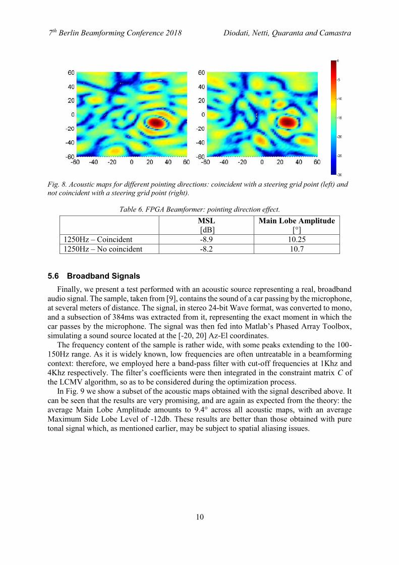
5.5 Pointing effects
To see the effect of the steering direction, different tests were performed with the acoustic
source positioned precisely on a point of the steering grid and not. The results are shown in Fig.
8. Also in this case, we can see that the effect of non-coincidence of the pointing direction with
an acoustic pixel is negligible in the final acoustic map.
7th Berlin Beamforming Conference 2018 Diodati, Netti, Quaranta and Camastra
10
Fig. 8. Acoustic maps for different pointing directions: coincident with a steering grid point (left) and
not coincident with a steering grid point (right).
Table 6. FPGA Beamformer: pointing direction effect.
MSL
[dB] Main Lobe Amplitude
[°]
1250Hz – Coincident -8.9 10.25
1250Hz – No coincident -8.2 10.7
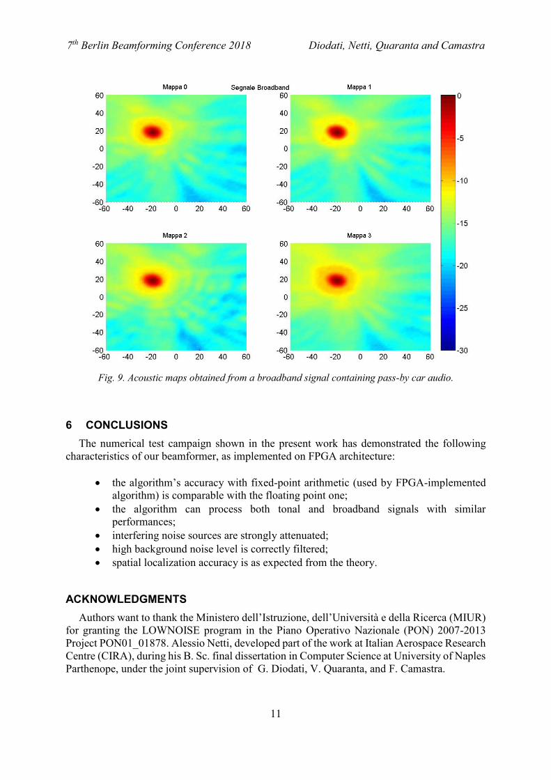
5.6 Broadband Signals
Finally, we present a test performed with an acoustic source representing a real, broadband
audio signal. The sample, taken from [9], contains the sound of a car passing by the microphone,
at several meters of distance. The signal, in stereo 24-bit Wave format, was converted to mono,
and a subsection of 384ms was extracted from it, representing the exact moment in which the
car passes by the microphone. The signal was then fed into Matlab’s Phased Array Toolbox,
simulating a sound source located at the [-20, 20] Az-El coordinates.
The frequency content of the sample is rather wide, with some peaks extending to the 100-
150Hz range. As it is widely known, low frequencies are often untreatable in a beamforming
context: therefore, we employed here a band-pass filter with cut-off frequencies at 1Khz and
4Khz respectively. The filter’s coefficients were then integrated in the constraint matrix C of
the LCMV algorithm, so as to be considered during the optimization process.
In Fig. 9 we show a subset of the acoustic maps obtained with the signal described above. It
can be seen that the results are very promising, and are again as expected from the theory: the
average Main Lobe Amplitude amounts to 9.4° across all acoustic maps, with an average
Maximum Side Lobe Level of -12db. These results are better than those obtained with pure
tonal signal which, as mentioned earlier, may be subject to spatial aliasing issues.
7th Berlin Beamforming Conference 2018 Diodati, Netti, Quaranta and Camastra
11
Fig. 9. Acoustic maps obtained from a broadband signal containing pass-by car audio.
6 CONCLUSIONS
The numerical test campaign shown in the present work has demonstrated the following
characteristics of our beamformer, as implemented on FPGA architecture:
the algorithm’s accuracy with fixed-point arithmetic (used by FPGA-implemented
algorithm) is comparable with the floating point one;
the algorithm can process both tonal and broadband signals with similar
performances;
interfering noise sources are strongly attenuated;
high background noise level is correctly filtered;
spatial localization accuracy is as expected from the theory.
ACKNOWLEDGMENTS
Authors want to thank the Ministero dell’Istruzione, dell’Università e della Ricerca (MIUR)
for granting the LOWNOISE program in the Piano Operativo Nazionale (PON) 2007-2013
Project PON01_01878. Alessio Netti, developed part of the work at Italian Aerospace Research
Centre (CIRA), during his B. Sc. final dissertation in Computer Science at University of Naples
Parthenope, under the joint supervision of G. Diodati, V. Quaranta, and F. Camastra.
7th Berlin Beamforming Conference 2018 Diodati, Netti, Quaranta and Camastra
12
REFERENCES
[1] Diodati G. and Quaranta V. “Acoustic sensors array for pass-by noise measurements:
Antenna design“. Proceedings of International Congress on Sound and Vibration
ICSV22, July 2015.
[2] ISO 362:2007 measurement of noise emitted by accelerating road vehicles –
engineering method – part 1: M and n categories.
[3] Frost O. “An algorithm for linearly constrained adaptive array processing”. Proceedings
of the IEEE, 60:926–935, August 1972.
[4] Zimmermann B. and Studer C. “Fpga-based real-time acoustic camera prototype”.
Technical report, ETH Zurich, Integrated Systems Laboratory, Zurich, Switzerland.
[5] Losada R. “Practical fir filter design in MATLAB”, March 2003.
[6] Xilinx. Vivado design suite user guide, high-level synthesis, May 2014.
[7] Netti A., Diodati G., Camastra F. and Quaranta V. “FPGA implementation of a real-
time filter and sum beamformer for acoustic antenna”. In: INTER-NOISE 2015 - 44th
International Congress and Exposition on Noise Control Engineering. 1-13, The
Institute of Noise Control Engineering of the USA, Inc., San Francisco Marriott
Marquis Hotel, USA, 2015.
[8] Christensen J.J. and Hald J., “Beamforming - A Technical Review”, Bruel & Kjær
Sound & Vibration Measurement A/S, 2004.
[9] Pass-by car audio sample: https://www.freesound.org/people/volivieri/sounds/39012/