Embed Size (px)
Citation preview
Cinemixman.lwp
CinemiX
OWNERS MANUAL
Cinemix manual page: 1
Cinemix Manualversion: 1.3
Introduction and Product Overview
1.0 The Chassis system - description
1.1 Cinemix chassis
2.0 Master section - description
2.1 Solo Section2.2 Meters to main2.3 CRM Section2.4 DECODER/ENCODER Active2.5 CRM control room monitor2.6 Oscillator / talkback section2.7 Talk back section2.8 Dynamics section2.9 Aux section2.10 Studio 1/2 section2.11 Metering2.12 Master in/outputs2.13 Recall/automation2.14 Tape switch
2.0 FILM MASTER
2.15 Solo Section2.16 Meters to main2.17 CRM Section2.18 DECODER/ENCODER Active2.19 CRM control room monitor2.20 Oscillator / talkback section2.21 Talk back section2.22 Dynamics section2.23 Aux section2.24 Studio 1/2 section2.25 Metering2.26 Master in/outputs2.27 Recall/automation2.28 Tape switch
3.0 "Dual-Path" mono module - description
3.1 Channel section3.2 Equalizer section Chan path3.3 Aux 1-4 section3.4 Pan pot
Cinemix manual page: 2
3.5 Phase switch3.6 Insert3.7 Sel switch3.8 SOLO3.9 Mute function3.10 Fader3.11 CHAN/MIX status section3.12 MIX path3.13 LCRS pan-pot3.14 CHAN/MIX path in/outputs
4.0 Dual Stereo return module
4.1 Input ssection4.2 Equalizer sections4.3 Aux send 1-4 section4.4 Status section4.5 Aux 5-10 section4.6 Equalizer section4.7 Balance pot4.8 Status section B path4.9 In/outputs
5.0 Patchbay - description
5.1 Patchbay points
6.0 Instructions for operation
6.1 The Tracking session6.2 The Playback session6.3 The Overdub session6.4 The REmix session6.5 MIDI or Virtual session6.6 Surround mixing
7.0 Installation - electrical
7.1 Local Electrical Voltage7.2 Electrical Wiring
8.0 Installation - audio
8.1 Interface with Power Amps8.2 The Initial Hook-up8.3 Shields & Grounds of Equipment
Cinemix manual page: 3
9.0 Troubleshooting and servicing
9.1 Troubleshooting9.2 Removing a module9.3 Patchbay - servicing
10.0 Connectors
10.1 Master section connectors10.2 Patchbay connectors
11.0 Specifications
12.0 Signal flow master section
13.0 Signal flow input module
14.0 System signal flow Cinemix
15.0 Interfacingwith external equipment
16.0 Interfacing with DS4E / SDU4
17.0 Interfacing with SEU4 / SDU4
18.0 Interfacing with JS-3000
19.0 Installation and alignment of the Control Room Monitor Matrix
19.1 Installation and alignment of the matrix module
20.0 Conformity safety
21.0 Product safety
Cinemix manual page: 4
Letter from the Prez
Dear Cinemix owner,
The Cinemix was created using the latest in computer aided design and assemblingtechnology and incorporates the most advanced circuit components availablewhich results in Cinemix being another D&R product unsurpassed in theelectronics industry.
In D&R's quest to "raise the standard", Cinemix is designed and manufactured tothe highest degree. We are confident that Cinemix will play the central roll inproducing "state of the art" recordings for many years and wish you much success.
We value your suggestions and would appreciate you taking the time to completeand return the questionnaire included at the front of this manual (once youbecome familiar with your Cinemix). We listen and learn from your comments and you can be assured that our researchand development department will take your comments very serious.
With kind regards,
Duco de RijkPresident D&R Electronica Weesp b.v.
Cinemix manual page: 5
RAISINGTHE
STANDARD
Cinemix Recording ConsoleThe D&R Cinemix is a 24 buss, dual path in-line format recording and mixingconsole designed to take the central role in a recording/mixing facility. With up to 30 projects storable, the wasted time between sessions is a thing ofthe past. An essential part of Cinemix is his ARM (Advanced Routing Multiplex). With ARM you can digitally route any input in Cinemix to a number of placesand be able to recall all stored setups by a couple of key strokes. This featurealone saves valuable time between sessions.A first in mixing console technology is Cinemix's surround master section withthe ability to mixdown a 5.1 surround mix, fully automated.Easy monitoring of all surround outputs is standard and automated Joystickswith Virtual Vision makes 360 degrees panning very easy to lay down in the finalmix.Completely modular, Cinemix can be configured precisely to suit your particularsystem requirements. A Cinemix standard is the internally wired patchbay on theright end and interfaces with all external equipment using 25 pin sub D connectors, and chassis mount XLR connectors.
To become completely familiar with your Cinemix and gain the maximum benefitfrom his use, we recommend that you read this manual thoroughly. It will provide important information about all aspects of Cinemix including;installation, operation, and servicing.
Head Office / Factory
D&R Electronica Weesp B.V.Rijnkade 15B1382 GS WeespThe Netherlands
Tel: (-) 31 294 418 014Fax: (-) 31 294 416 987Website: http://www.d-r.nlE-mail: [email protected]
Cinemix manual page: 6
Cinemix's CHASSIS SYSTEM1.0 Cinemix's Chassis
The Cinemix is available in two frame sizes; 32 and 48. The basic frame has oneblank module located on the extreme left of the frame. The three blankspositioned right from the master section can be replaced by an optional FilmStems module. This is a module that returns 24 track machine outputs directlyinto the CRM summing busses for monitoring pre-recordings.The blank on the far left side of the frame cannot be replaced with an inputmodule as they conceal mechanical constructions and internal wiring. Included with Cinemix's frame are; the master section with associated VUmetering, patchbay, all internal cable harnessing, and rack mount power supply.
Frame 32The frame 32 will fit 32 dual path mono, 3 optional Stems modules and amiaximum of 5 dual path stereo modules, the master section, and patchbay.
Frame 32 standard configuration:From left to right; 24 dual path mono modules, master section, 3 blank modules,8 dual path mono modules and a maximum of 5 dual path stereo return modules(10 stereo returns), and pacthbay.
Frame 48The frame 48 will fit 48 dual path mono, 3 optional stems modules, 3blanks and5 dual path stereo modules, master section and patchbay.
Frame 48 standard configuration:From left to right; 32 dual path mono modules, master section, 3 optional stemsmodules, 16 dual path mono modules, 5 dual stereo return modules (10 stereoreturns), and patchbay.
Note: Cinemix's patchbay can be ordered on either end of the frame for a smallprice increase covering extra mechanical work for re-arranging of internalmounting of automation and Dynamics PCB's.
Cinemix manual page: 7
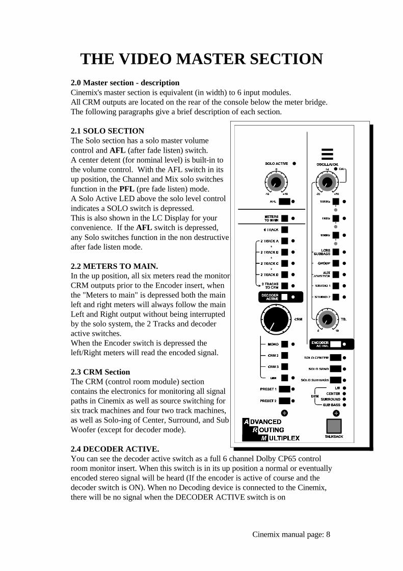
THE VIDEO MASTER SECTION2.0 Master section - descriptionCinemix's master section is equivalent (in width) to 6 input modules. All CRM outputs are located on the rear of the console below the meter bridge. The following paragraphs give a brief description of each section.
2.1 SOLO SECTIONThe Solo section has a solo master volumecontrol and AFL (after fade listen) switch. A center detent (for nominal level) is built-in tothe volume control. With the AFL switch in itsup position, the Channel and Mix solo switchesfunction in the PFL (pre fade listen) mode. A Solo Active LED above the solo level controlindicates a SOLO switch is depressed. This is also shown in the LC Display for yourconvenience. If the AFL switch is depressed,any Solo switches function in the non destructiveafter fade listen mode.
2.2 METERS TO MAIN.In the up position, all six meters read the monitorCRM outputs prior to the Encoder insert, whenthe "Meters to main" is depressed both the mainleft and right meters will always follow the mainLeft and Right output without being interruptedby the solo system, the 2 Tracks and decoderactive switches.When the Encoder switch is depressed theleft/Right meters will read the encoded signal.
2.3 CRM Section The CRM (control room module) sectioncontains the electronics for monitoring all signalpaths in Cinemix as well as source switching forsix track machines and four two track machines,as well as Solo-ing of Center, Surround, and SubWoofer (except for decoder mode).
2.4 DECODER ACTIVE.You can see the decoder active switch as a full 6 channel Dolby CP65 controlroom monitor insert. When this switch is in its up position a normal or eventuallyencoded stereo signal will be heard (If the encoder is active of course and thedecoder switch is ON). When no Decoding device is connected to the Cinemix,there will be no signal when the DECODER ACTIVE switch is on
Cinemix manual page: 8

ENCODER ACTIVE.This switch changes the Main output signal from the console to the Encoderoutput of an externally connected Encoder. The Surround left/Right signal willbe mono summed .
2.5 CRM CONTROL ROOM MONITOR.The large CRM knob controls the total of 6 outgoing levels to the control roommonitor power amps. This encoder controls allsix tracks with a superb tracking and levelrepeatability. Attenuation of the CRM is alwaysshown in the LC display in the first level of themenu. It ranges from 0dB down to -63dB in0.5dB steps and then it mutes the CRMcompletely. The Cinemix has three CRMsystems intended for alternative stereo nearfieldmonitors which are switchable via the CRM 2,and 3 switches. Each alternate speaker systemhave their own ground compensated balancedXLR output for easy interchange of nearfields byfree lance engineers. The main CRM outputtogether with the Center Stereo Surround, andSubbass output are on a 25 pole sub Dconnector. Also fitted on the back of the mastersection are the sub D connectors for theencoding and decoding surround processors.
MONOThe mono switch lets you check monocompatability.The Mono switch allows the userto check for any out-of-phase signals or simplymonitoring your mix in mono.
DIMThe dim switch temporarily dims Cinemix's CRMlevel by a pre programmable amount ofattenuation. This dimming circuitry is also drivenby the oscillator circuitry as well as the Talkbackcircuitry. The LC Display shows the amount ofdimming when activated.
PRESET 1/2These switches lets you determine a fixed CRMlevel, programmable in the automation. In this way it is always possible to returnto a reference level of surround monitoring. By turning the CRM control to adesired level and pushing the Preset 1 or 2 for about 7 seconds the presentattenuation level is stored. The preset led will lit, when storage is active. Two fixed levels can be set in this way.
Cinemix manual page: 9
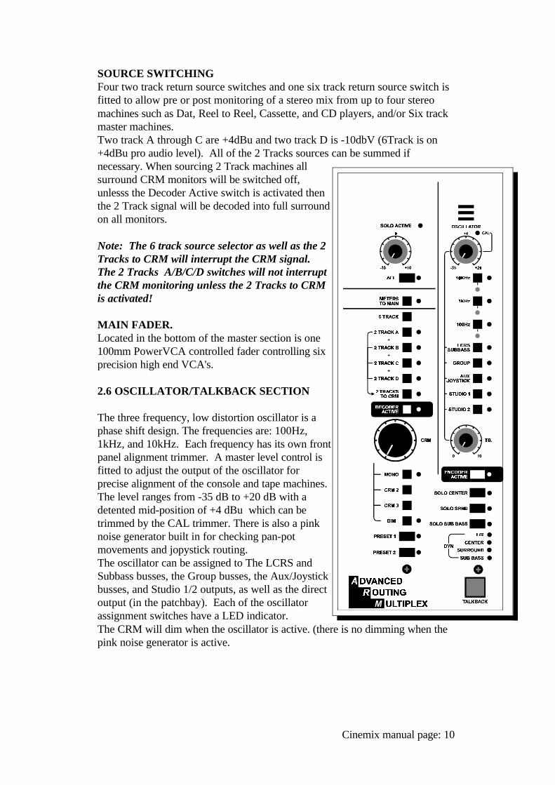
SOURCE SWITCHINGFour two track return source switches and one six track return source switch isfitted to allow pre or post monitoring of a stereo mix from up to four stereomachines such as Dat, Reel to Reel, Cassette, and CD players, and/or Six track master machines.Two track A through C are +4dBu and two track D is -10dbV (6Track is on+4dBu pro audio level). All of the 2 Tracks sources can be summed ifnecessary. When sourcing 2 Track machines allsurround CRM monitors will be switched off,unlesss the Decoder Active switch is activated then the 2 Track signal will be decoded into full surroundon all monitors.
Note: The 6 track source selector as well as the 2Tracks to CRM will interrupt the CRM signal.The 2 Tracks A/B/C/D switches will not interruptthe CRM monitoring unless the 2 Tracks to CRMis activated!
MAIN FADER.Located in the bottom of the master section is one100mm PowerVCA controlled fader controlling sixprecision high end VCA's.
2.6 OSCILLATOR/TALKBACK SECTION
The three frequency, low distortion oscillator is aphase shift design. The frequencies are: 100Hz,1kHz, and 10kHz. Each frequency has its own frontpanel alignment trimmer. A master level control isfitted to adjust the output of the oscillator forprecise alignment of the console and tape machines.The level ranges from -35 dB to +20 dB with adetented mid-position of +4 dBu which can betrimmed by the CAL trimmer. There is also a pinknoise generator built in for checking pan-potmovements and jopystick routing.The oscillator can be assigned to The LCRS andSubbass busses, the Group busses, the Aux/Joystickbusses, and Studio 1/2 outputs, as well as the directoutput (in the patchbay). Each of the oscillatorassignment switches have a LED indicator. The CRM will dim when the oscillator is active. (there is no dimming when the pink noise generator is active.
Cinemix manual page: 10
2.7 TALKBACK SECTIONA one way communication system is built into Cinemix. The built-in talkbackmic can feed the LCRS/Sub Bass Groups, Auxes/Joystick busses, and/orStudio1/2 outputs. The momentary TB talkback switch activates the internal electretmicrophone while dimming the main CRM monitor speakers.
2.8 DYNAMICS SECTIONFour LEDS indicate whether the optional virtual dynamics is active on any of themain output signals. (How the dynamics work will be discussed later in a specific13.00 dynamics section).
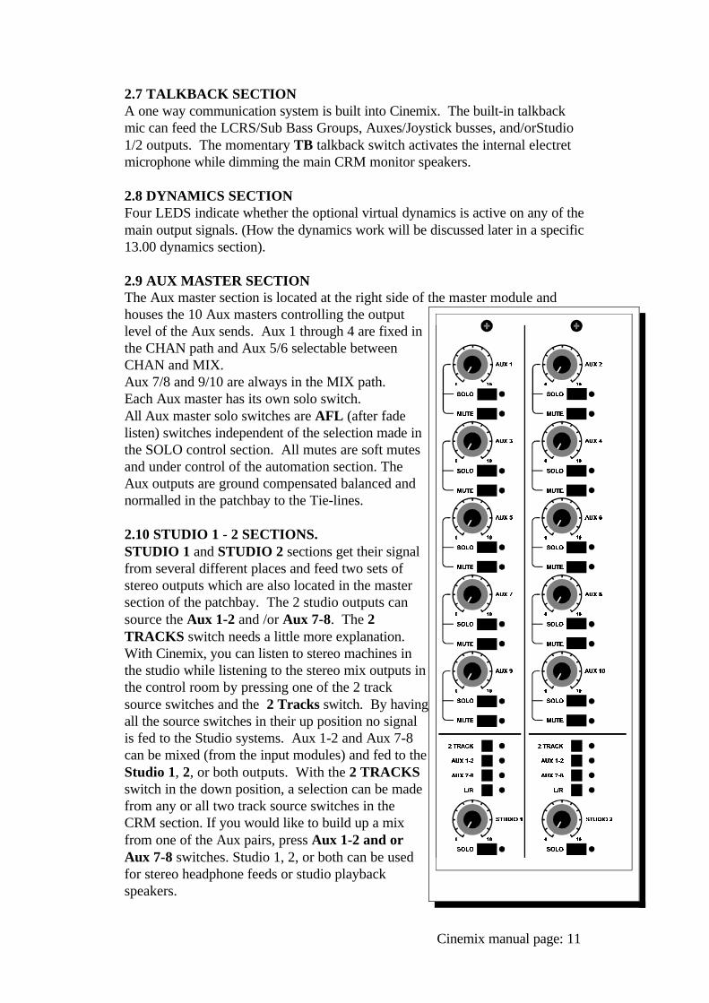
2.9 AUX MASTER SECTIONThe Aux master section is located at the right side of the master module andhouses the 10 Aux masters controlling the outputlevel of the Aux sends. Aux 1 through 4 are fixed inthe CHAN path and Aux 5/6 selectable betweenCHAN and MIX. Aux 7/8 and 9/10 are always in the MIX path. Each Aux master has its own solo switch. All Aux master solo switches are AFL (after fadelisten) switches independent of the selection made inthe SOLO control section. All mutes are soft mutesand under control of the automation section. TheAux outputs are ground compensated balanced andnormalled in the patchbay to the Tie-lines.
2.10 STUDIO 1 - 2 SECTIONS.STUDIO 1 and STUDIO 2 sections get their signalfrom several different places and feed two sets ofstereo outputs which are also located in the mastersection of the patchbay. The 2 studio outputs cansource the Aux 1-2 and /or Aux 7-8. The 2TRACKS switch needs a little more explanation. With Cinemix, you can listen to stereo machines inthe studio while listening to the stereo mix outputs inthe control room by pressing one of the 2 tracksource switches and the 2 Tracks switch. By havingall the source switches in their up position no signalis fed to the Studio systems. Aux 1-2 and Aux 7-8can be mixed (from the input modules) and fed to theStudio 1, 2, or both outputs. With the 2 TRACKSswitch in the down position, a selection can be madefrom any or all two track source switches in theCRM section. If you would like to build up a mixfrom one of the Aux pairs, press Aux 1-2 and orAux 7-8 switches. Studio 1, 2, or both can be usedfor stereo headphone feeds or studio playbackspeakers.
Cinemix manual page: 11
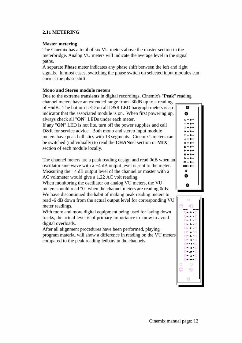
2.11 METERING
Master meteringThe Cinemix has a total of six VU meters above the master section in themeterbridge. Analog VU meters will indicate the average level in the signalpaths.A separate Phase meter indicates any phase shift between the left and rightsignals. In most cases, switching the phase switch on selected input modules cancorrect the phase shift.
Mono and Stereo module metersDue to the extreme transients in digital recordings, Cinemix's "Peak" readingchannel meters have an extended range from -30dB up to a readingof +6dB. The bottom LED on all D&R LED bargraph meters is anindicator that the associated module is on. When first powering up,always check all "ON" LEDs under each meter. If any "ON" LED is not lite, turn off the power supplies and callD&R for service advice. Both mono and stereo input modulemeters have peak ballistics with 13 segments. Cinemix's meters canbe switched (individually) to read the CHANnel section or MIXsection of each module locally.
The channel meters are a peak reading design and read 0dB when anoscillator sine wave with a +4 dB output level is sent to the meter.Measuring the +4 dB output level of the channel or master with aAC voltmeter would give a 1.22 AC volt reading. When monitoring the oscillator on analog VU meters, the VUmeters should read "0" when the channel meters are reading 0dB.We have discontinued the habit of making peak reading meters toread -6 dB down from the actual output level for corresponding VUmeter readings.With more and more digital equipment being used for laying downtracks, the actual level is of primary importance to know to avoiddigital overloads.After all alignment procedures have been performed, playingprogram material will show a difference in reading on the VU meterscompared to the peak reading ledbars in the channels.
Cinemix manual page: 12
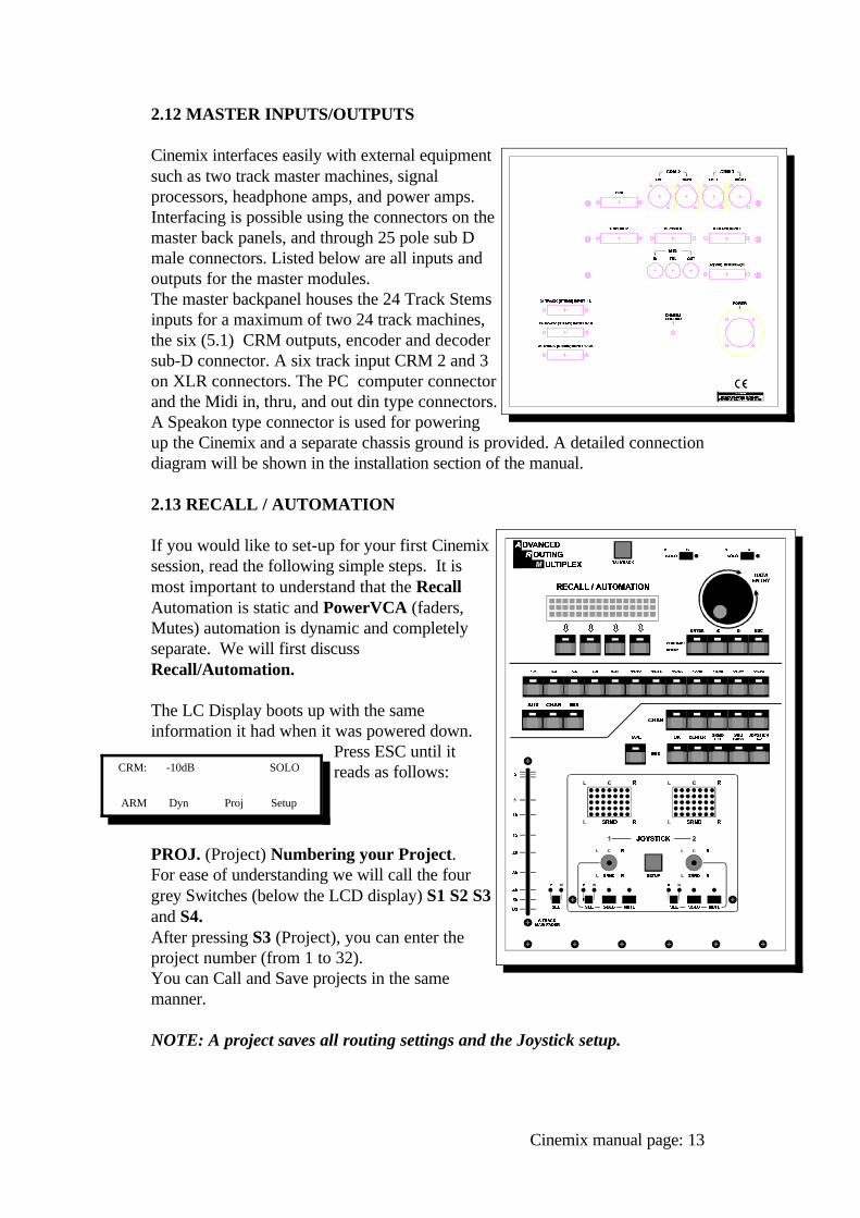
2.12 MASTER INPUTS/OUTPUTS
Cinemix interfaces easily with external equipmentsuch as two track master machines, signalprocessors, headphone amps, and power amps.Interfacing is possible using the connectors on themaster back panels, and through 25 pole sub Dmale connectors. Listed below are all inputs andoutputs for the master modules. The master backpanel houses the 24 Track Stemsinputs for a maximum of two 24 track machines,the six (5.1) CRM outputs, encoder and decodersub-D connector. A six track input CRM 2 and 3on XLR connectors. The PC computer connectorand the Midi in, thru, and out din type connectors.A Speakon type connector is used for poweringup the Cinemix and a separate chassis ground is provided. A detailed connectiondiagram will be shown in the installation section of the manual.
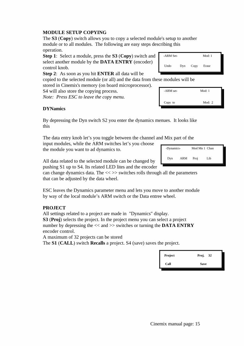
2.13 RECALL / AUTOMATION
If you would like to set-up for your first Cinemixsession, read the following simple steps. It ismost important to understand that the RecallAutomation is static and PowerVCA (faders,Mutes) automation is dynamic and completelyseparate. We will first discussRecall/Automation.
The LC Display boots up with the sameinformation it had when it was powered down.
Press ESC until itreads as follows:
PROJ. (Project) Numbering your Project.For ease of understanding we will call the fourgrey Switches (below the LCD display) S1 S2 S3and S4.After pressing S3 (Project), you can enter theproject number (from 1 to 32). You can Call and Save projects in the samemanner.
NOTE: A project saves all routing settings and the Joystick setup.
Cinemix manual page: 13
CRM: -10dB SOLO
ARM Dyn Proj Setup
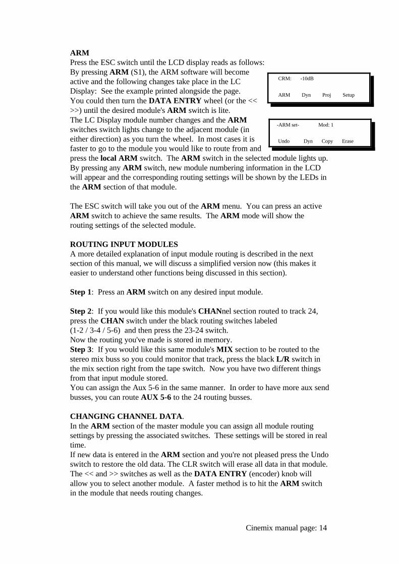
ARMPress the ESC switch until the LCD display reads as follows:By pressing ARM (S1), the ARM software will becomeactive and the following changes take place in the LCDisplay: See the example printed alongside the page.You could then turn the DATA ENTRY wheel (or the <<>>) until the desired module's ARM switch is lite. The LC Display module number changes and the ARMswitches switch lights change to the adjacent module (ineither direction) as you turn the wheel. In most cases it isfaster to go to the module you would like to route from andpress the local ARM switch. The ARM switch in the selected module lights up.By pressing any ARM switch, new module numbering information in the LCDwill appear and the corresponding routing settings will be shown by the LEDs inthe ARM section of that module.
The ESC switch will take you out of the ARM menu. You can press an activeARM switch to achieve the same results. The ARM mode will show therouting settings of the selected module.
ROUTING INPUT MODULESA more detailed explanation of input module routing is described in the nextsection of this manual, we will discuss a simplified version now (this makes iteasier to understand other functions being discussed in this section).
Step 1: Press an ARM switch on any desired input module.
Step 2: If you would like this module's CHANnel section routed to track 24,press the CHAN switch under the black routing switches labeled (1-2 / 3-4 / 5-6) and then press the 23-24 switch.Now the routing you've made is stored in memory.Step 3: If you would like this same module's MIX section to be routed to thestereo mix buss so you could monitor that track, press the black L/R switch inthe mix section right from the tape switch. Now you have two different thingsfrom that input module stored.You can assign the Aux 5-6 in the same manner. In order to have more aux sendbusses, you can route AUX 5-6 to the 24 routing busses.
CHANGING CHANNEL DATA.In the ARM section of the master module you can assign all module routingsettings by pressing the associated switches. These settings will be stored in realtime.If new data is entered in the ARM section and you're not pleased press the Undoswitch to restore the old data. The CLR switch will erase all data in that module.The << and >> switches as well as the DATA ENTRY (encoder) knob willallow you to select another module. A faster method is to hit the ARM switchin the module that needs routing changes.
Cinemix manual page: 14
CRM: -10dB
ARM Dyn Proj Setup
-ARM set- Mod: 1
Undo Dyn Copy Erase
MODULE SETUP COPYINGThe S3 (Copy) switch allows you to copy a selected module's setup to anothermodule or to all modules. The following are easy steps describing thisoperation.Step 1: Select a module, press the S3 (Copy) switch andselect another module by the DATA ENTRY (encoder)control knob.Step 2: As soon as you hit ENTER all data will becopied to the selected module (or all) and the data from these modules will bestored in Cinemix's memory (on board microprocessor).S4 will also store the copying process. Note: Press ESC to leave the copy menu.
DYNamics
By depressing the Dyn switch S2 you enter the dynamics menues. It looks likethis
The data entry knob let’s you toggle between the channel and Mix part of theinput modules, while the ARM switches let’s you choosethe module you want to ad dynamics to.
All data related to the selected module can be changed bypushing S1 up to S4. Its related LED lites and the encodercan change dynamics data. The << >> switches rolls through all the parametersthat can be adjusted by the data wheel.
ESC leaves the Dynamics parameter menu and lets you move to another moduleby way of the local module’s ARM switch or the Data entree wheel.
PROJECT All settings related to a project are made in "Dynamics" display.S3 (Proj) selects the project. In the project menu you can select a projectnumber by depressing the << and >> switches or turning the DATA ENTRYencoder control.A maximum of 32 projects can be storedThe S1 (CALL) switch Recalls a project. S4 (save) saves the project.
Cinemix manual page: 15
-ARM Set- Mod: 1
Undo Dyn Copy Erase
-ARM set- Mod: 1
Copy to Mod: 2
-Dynamics- Mod Mn 1 Chan
Dyn ARM Proj Lib
Project Proj. 32
Call Save
Cinemix's SET menu
When you press Cinemix's Set (S4) switch, the LC Displayreads as follows:
By pressing SetM (S1) all MUTE switches will mute. Pressing ResetM (S2) all mute switches will un-mute.
AUTOMATION.Paragraph 12.0 PowerVca automation will outline the setup and use of D&R'sPowerVCA SMPTE based Automation. Since this section of Cinemix's manualis an insert, the page numbers will not be in sequence with the balance of thismanual. Optional PowerFade (D&R's moving fader automation) is available,however not discussed in this section.
ARM/SET FOR AUTOMATED JOYSTICKS.
A unique feature in Cinemix are the two automated joysticks with its VirtualVision concept of showing you the position of the audio signal when controlledfrom D&R's PowerVCA automation.The "Set-up" switch serves actually the same purpose as the ARM switches inthe modules.
ASSIGNING A CHANNEL TO A JOYSTICK
To assign a channel to a Joystick follow the next steps.
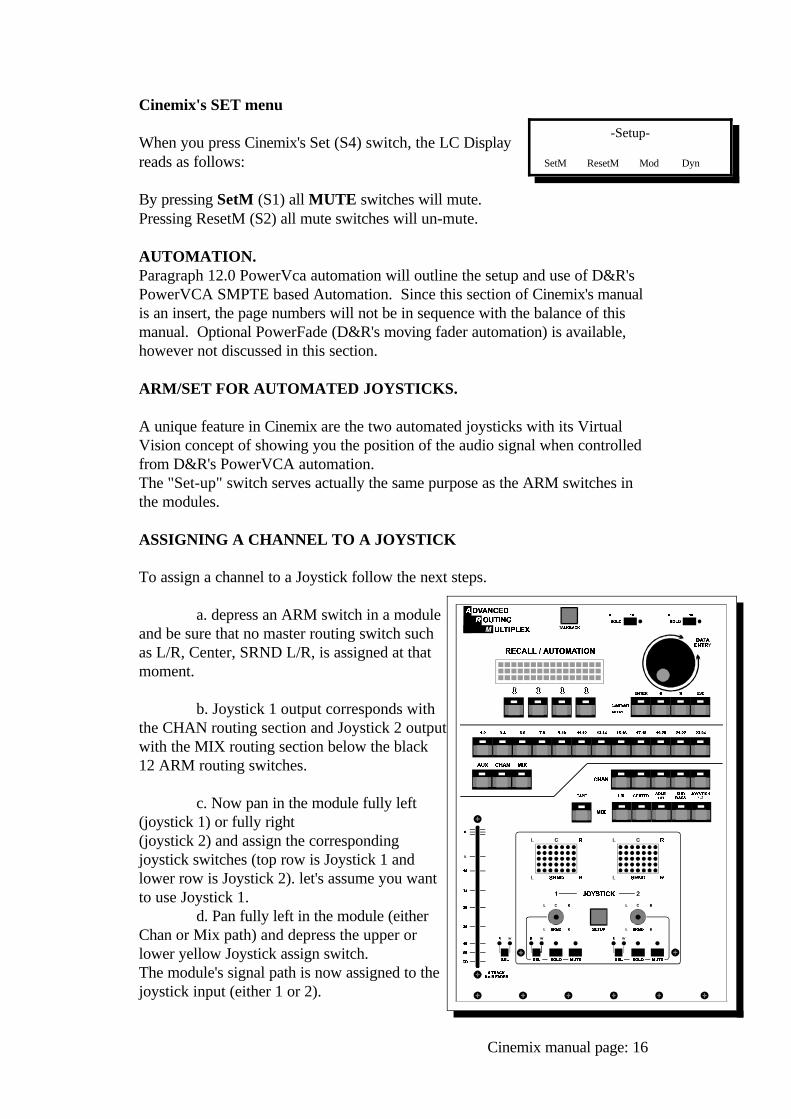
a. depress an ARM switch in a moduleand be sure that no master routing switch suchas L/R, Center, SRND L/R, is assigned at thatmoment.
b. Joystick 1 output corresponds withthe CHAN routing section and Joystick 2 outputwith the MIX routing section below the black12 ARM routing switches.
c. Now pan in the module fully left(joystick 1) or fully right (joystick 2) and assign the correspondingjoystick switches (top row is Joystick 1 andlower row is Joystick 2). let's assume you wantto use Joystick 1.
d. Pan fully left in the module (eitherChan or Mix path) and depress the upper orlower yellow Joystick assign switch. The module's signal path is now assigned to thejoystick input (either 1 or 2).
Cinemix manual page: 16
-Setup-
SetM ResetM Mod Dyn
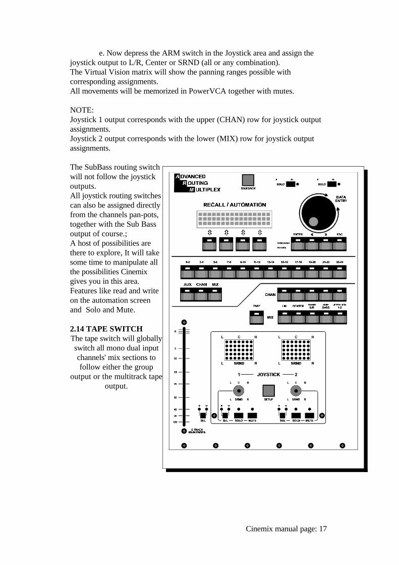
e. Now depress the ARM switch in the Joystick area and assign thejoystick output to L/R, Center or SRND (all or any combination). The Virtual Vision matrix will show the panning ranges possible withcorresponding assignments.All movements will be memorized in PowerVCA together with mutes.
NOTE:Joystick 1 output corresponds with the upper (CHAN) row for joystick outputassignments.Joystick 2 output corresponds with the lower (MIX) row for joystick outputassignments.
The SubBass routing switchwill not follow the joystickoutputs.All joystick routing switchescan also be assigned directlyfrom the channels pan-pots,together with the Sub Bassoutput of course.;A host of possibilities arethere to explore, It will takesome time to manipulate allthe possibilities Cinemixgives you in this area.Features like read and writeon the automation screenand Solo and Mute.
2.14 TAPE SWITCHThe tape switch will globallyswitch all mono dual inputchannels' mix sections tofollow either the group
output or the multitrack tapeoutput.
Cinemix manual page: 17
THE FILM MASTER SECTION2.15 Master section - descriptionCinemix's film master section is equivalent (in width) to 6 input modules. All CRM outputs are located on the rear of the console below the meter bridge. The following paragraphs give a brief description of each section.
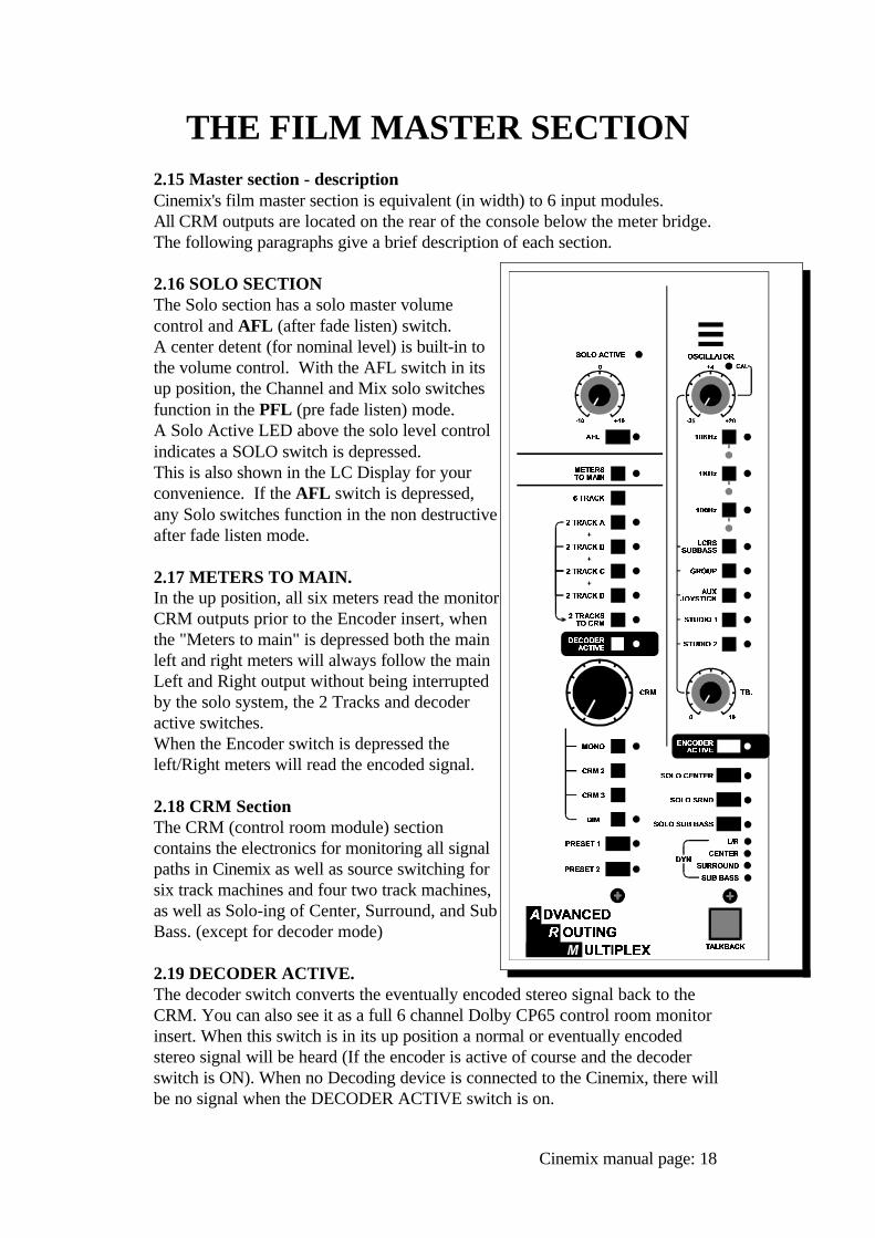
2.16 SOLO SECTIONThe Solo section has a solo master volumecontrol and AFL (after fade listen) switch. A center detent (for nominal level) is built-in tothe volume control. With the AFL switch in itsup position, the Channel and Mix solo switchesfunction in the PFL (pre fade listen) mode. A Solo Active LED above the solo level controlindicates a SOLO switch is depressed. This is also shown in the LC Display for yourconvenience. If the AFL switch is depressed,any Solo switches function in the non destructiveafter fade listen mode.
2.17 METERS TO MAIN.In the up position, all six meters read the monitorCRM outputs prior to the Encoder insert, whenthe "Meters to main" is depressed both the mainleft and right meters will always follow the mainLeft and Right output without being interruptedby the solo system, the 2 Tracks and decoderactive switches.When the Encoder switch is depressed theleft/Right meters will read the encoded signal.
2.18 CRM Section The CRM (control room module) sectioncontains the electronics for monitoring all signalpaths in Cinemix as well as source switching forsix track machines and four two track machines,as well as Solo-ing of Center, Surround, and SubBass. (except for decoder mode)
2.19 DECODER ACTIVE.The decoder switch converts the eventually encoded stereo signal back to theCRM. You can also see it as a full 6 channel Dolby CP65 control room monitorinsert. When this switch is in its up position a normal or eventually encodedstereo signal will be heard (If the encoder is active of course and the decoderswitch is ON). When no Decoding device is connected to the Cinemix, there willbe no signal when the DECODER ACTIVE switch is on.
Cinemix manual page: 18
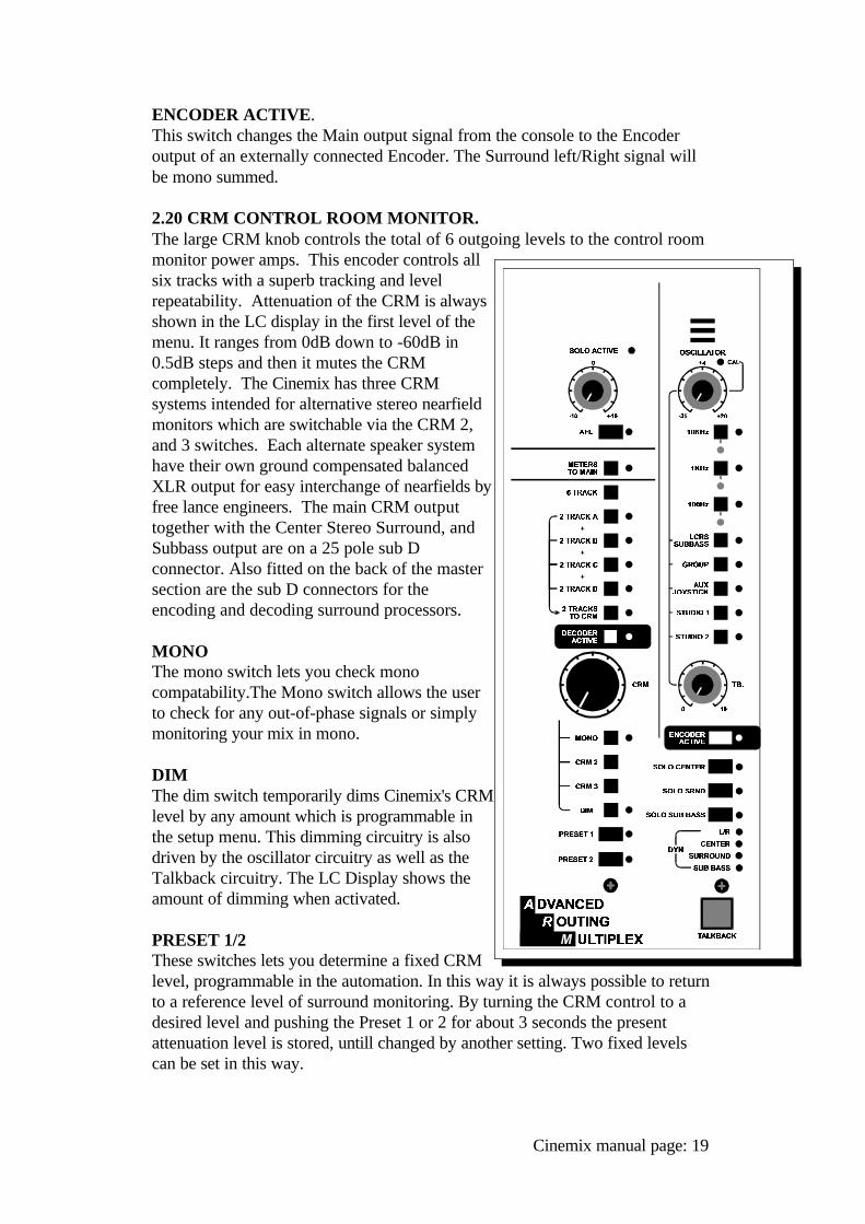
ENCODER ACTIVE.This switch changes the Main output signal from the console to the Encoderoutput of an externally connected Encoder. The Surround left/Right signal willbe mono summed.
2.20 CRM CONTROL ROOM MONITOR.The large CRM knob controls the total of 6 outgoing levels to the control roommonitor power amps. This encoder controls allsix tracks with a superb tracking and levelrepeatability. Attenuation of the CRM is alwaysshown in the LC display in the first level of themenu. It ranges from 0dB down to -60dB in0.5dB steps and then it mutes the CRMcompletely. The Cinemix has three CRMsystems intended for alternative stereo nearfieldmonitors which are switchable via the CRM 2,and 3 switches. Each alternate speaker systemhave their own ground compensated balancedXLR output for easy interchange of nearfields byfree lance engineers. The main CRM outputtogether with the Center Stereo Surround, andSubbass output are on a 25 pole sub Dconnector. Also fitted on the back of the mastersection are the sub D connectors for theencoding and decoding surround processors.
MONOThe mono switch lets you check monocompatability.The Mono switch allows the userto check for any out-of-phase signals or simplymonitoring your mix in mono.
DIMThe dim switch temporarily dims Cinemix's CRMlevel by any amount which is programmable inthe setup menu. This dimming circuitry is alsodriven by the oscillator circuitry as well as theTalkback circuitry. The LC Display shows theamount of dimming when activated.
PRESET 1/2These switches lets you determine a fixed CRMlevel, programmable in the automation. In this way it is always possible to returnto a reference level of surround monitoring. By turning the CRM control to adesired level and pushing the Preset 1 or 2 for about 3 seconds the presentattenuation level is stored, untill changed by another setting. Two fixed levelscan be set in this way.
Cinemix manual page: 19
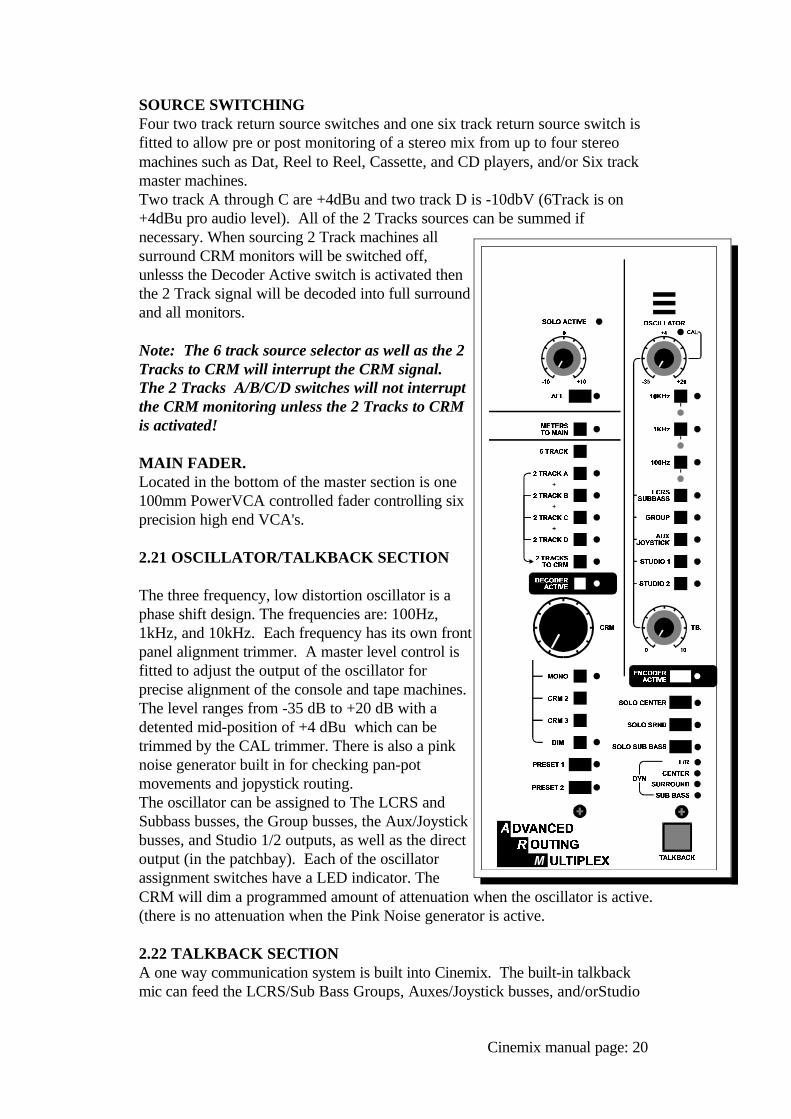
SOURCE SWITCHINGFour two track return source switches and one six track return source switch isfitted to allow pre or post monitoring of a stereo mix from up to four stereomachines such as Dat, Reel to Reel, Cassette, and CD players, and/or Six track master machines.Two track A through C are +4dBu and two track D is -10dbV (6Track is on+4dBu pro audio level). All of the 2 Tracks sources can be summed ifnecessary. When sourcing 2 Track machines allsurround CRM monitors will be switched off,unlesss the Decoder Active switch is activated then the 2 Track signal will be decoded into full surroundand all monitors.
Note: The 6 track source selector as well as the 2Tracks to CRM will interrupt the CRM signal.The 2 Tracks A/B/C/D switches will not interruptthe CRM monitoring unless the 2 Tracks to CRMis activated!
MAIN FADER.Located in the bottom of the master section is one100mm PowerVCA controlled fader controlling sixprecision high end VCA's.
2.21 OSCILLATOR/TALKBACK SECTION
The three frequency, low distortion oscillator is aphase shift design. The frequencies are: 100Hz,1kHz, and 10kHz. Each frequency has its own frontpanel alignment trimmer. A master level control isfitted to adjust the output of the oscillator forprecise alignment of the console and tape machines.The level ranges from -35 dB to +20 dB with adetented mid-position of +4 dBu which can betrimmed by the CAL trimmer. There is also a pinknoise generator built in for checking pan-potmovements and jopystick routing.The oscillator can be assigned to The LCRS andSubbass busses, the Group busses, the Aux/Joystickbusses, and Studio 1/2 outputs, as well as the directoutput (in the patchbay). Each of the oscillatorassignment switches have a LED indicator. TheCRM will dim a programmed amount of attenuation when the oscillator is active.(there is no attenuation when the Pink Noise generator is active.
2.22 TALKBACK SECTIONA one way communication system is built into Cinemix. The built-in talkbackmic can feed the LCRS/Sub Bass Groups, Auxes/Joystick busses, and/orStudio
Cinemix manual page: 20
1/2 outputs. The momentary TB talkback switch activates the internal electretmicrophone while dimming the main CRM monitor speakers.
2.23 DYNAMICS SECTIONFour LEDS indicate whether the optional virtual dynamics is active on any of themain output signals. (How the dynamics work will be discussed later in a specific13.00 dynamics section).
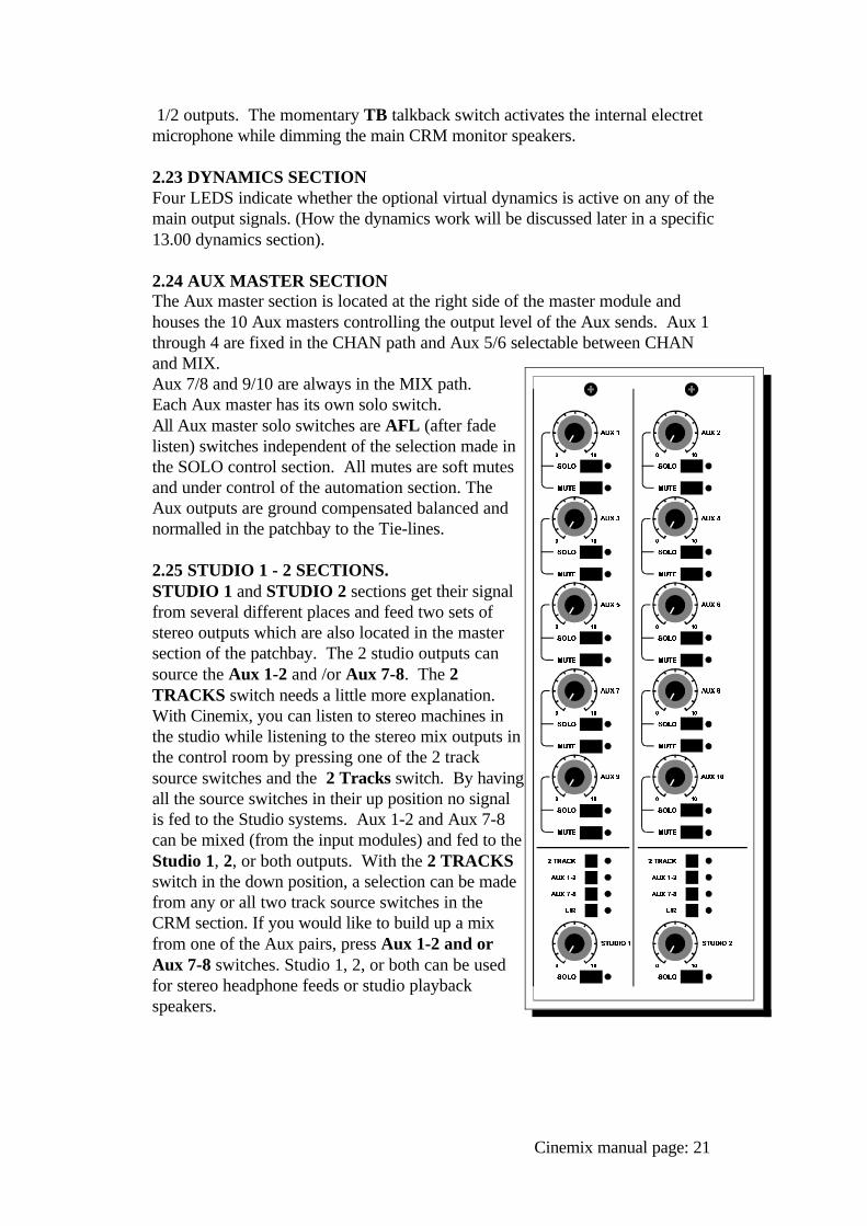
2.24 AUX MASTER SECTIONThe Aux master section is located at the right side of the master module andhouses the 10 Aux masters controlling the output level of the Aux sends. Aux 1through 4 are fixed in the CHAN path and Aux 5/6 selectable between CHANand MIX. Aux 7/8 and 9/10 are always in the MIX path. Each Aux master has its own solo switch. All Aux master solo switches are AFL (after fadelisten) switches independent of the selection made inthe SOLO control section. All mutes are soft mutesand under control of the automation section. TheAux outputs are ground compensated balanced andnormalled in the patchbay to the Tie-lines.
2.25 STUDIO 1 - 2 SECTIONS.STUDIO 1 and STUDIO 2 sections get their signalfrom several different places and feed two sets ofstereo outputs which are also located in the mastersection of the patchbay. The 2 studio outputs cansource the Aux 1-2 and /or Aux 7-8. The 2TRACKS switch needs a little more explanation. With Cinemix, you can listen to stereo machines inthe studio while listening to the stereo mix outputs inthe control room by pressing one of the 2 tracksource switches and the 2 Tracks switch. By havingall the source switches in their up position no signalis fed to the Studio systems. Aux 1-2 and Aux 7-8can be mixed (from the input modules) and fed to theStudio 1, 2, or both outputs. With the 2 TRACKSswitch in the down position, a selection can be madefrom any or all two track source switches in theCRM section. If you would like to build up a mixfrom one of the Aux pairs, press Aux 1-2 and orAux 7-8 switches. Studio 1, 2, or both can be usedfor stereo headphone feeds or studio playbackspeakers.
Cinemix manual page: 21
2.26 METERING
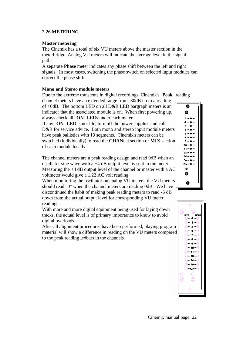
Master meteringThe Cinemix has a total of six VU meters above the master section in themeterbridge. Analog VU meters will indicate the average level in the signalpaths.A separate Phase meter indicates any phase shift between the left and rightsignals. In most cases, switching the phase switch on selected input modules cancorrect the phase shift.
Mono and Stereo module metersDue to the extreme transients in digital recordings, Cinemix's "Peak" readingchannel meters have an extended range from -30dB up to a readingof +6dB. The bottom LED on all D&R LED bargraph meters is anindicator that the associated module is on. When first powering up,always check all "ON" LEDs under each meter. If any "ON" LED is not lite, turn off the power supplies and callD&R for service advice. Both mono and stereo input module metershave peak ballistics with 13 segments. Cinemix's meters can beswitched (individually) to read the CHANnel section or MIX sectionof each module locally.
The channel meters are a peak reading design and read 0dB when anoscillator sine wave with a +4 dB output level is sent to the meter.Measuring the +4 dB output level of the channel or master with a ACvoltmeter would give a 1.22 AC volt reading. When monitoring the oscillator on analog VU meters, the VU metersshould read "0" when the channel meters are reading 0dB. We havediscontinued the habit of making peak reading meters to read -6 dBdown from the actual output level for corresponding VU meterreadings.With more and more digital equipment being used for laying downtracks, the actual level is of primary importance to know to avoiddigital overloads.After all alignment procedures have been performed, playing programmaterial will show a difference in reading on the VU meters comparedto the peak reading ledbars in the channels.
Cinemix manual page: 22
2.27 MASTER INPUTS/OUTPUTS
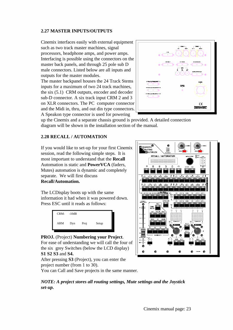
Cinemix interfaces easily with external equipmentsuch as two track master machines, signalprocessors, headphone amps, and power amps.Interfacing is possible using the connectors on themaster back panels, and through 25 pole sub Dmale connectors. Listed below are all inputs andoutputs for the master modules. The master backpanel houses the 24 Track Stemsinputs for a maximum of two 24 track machines,the six (5.1) CRM outputs, encoder and decodersub-D connector. A six track input CRM 2 and 3on XLR connectors. The PC computer connectorand the Midi in, thru, and out din type connectors.A Speakon type connector is used for poweringup the Cinemix and a separate chassis ground is provided. A detailed connectiondiagram will be shown in the installation section of the manual.
2.28 RECALL / AUTOMATION
If you would like to set-up for your first Cinemixsession, read the following simple steps. It ismost important to understand that the RecallAutomation is static and PowerVCA (faders,Mutes) automation is dynamic and completelyseparate. We will first discussRecall/Automation.
The LCDisplay boots up with the sameinformation it had when it was powered down.Press ESC until it reads as follows:
PROJ. (Project) Numbering your Project.For ease of understanding we will call the four ofthe six grey Switches (below the LCD display)S1 S2 S3 and S4.After pressing S3 (Project), you can enter theproject number (from 1 to 30). You can Call and Save projects in the same manner.
NOTE: A project stores all routing settings, Mute settings and the Joystickset-up.
Cinemix manual page: 23
CRM: -10dB
ARM Dyn Proj Setup
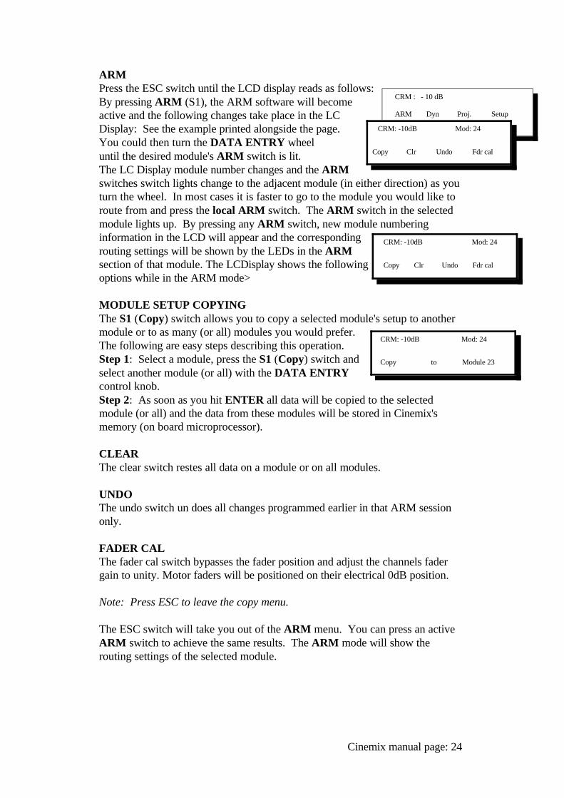
ARMPress the ESC switch until the LCD display reads as follows:By pressing ARM (S1), the ARM software will becomeactive and the following changes take place in the LCDisplay: See the example printed alongside the page.You could then turn the DATA ENTRY wheel until the desired module's ARM switch is lit.The LC Display module number changes and the ARMswitches switch lights change to the adjacent module (in either direction) as youturn the wheel. In most cases it is faster to go to the module you would like toroute from and press the local ARM switch. The ARM switch in the selectedmodule lights up. By pressing any ARM switch, new module numberinginformation in the LCD will appear and the correspondingrouting settings will be shown by the LEDs in the ARMsection of that module. The LCDisplay shows the followingoptions while in the ARM mode>
MODULE SETUP COPYINGThe S1 (Copy) switch allows you to copy a selected module's setup to anothermodule or to as many (or all) modules you would prefer.The following are easy steps describing this operation.Step 1: Select a module, press the S1 (Copy) switch andselect another module (or all) with the DATA ENTRY control knob.Step 2: As soon as you hit ENTER all data will be copied to the selectedmodule (or all) and the data from these modules will be stored in Cinemix'smemory (on board microprocessor).
CLEARThe clear switch restes all data on a module or on all modules.
UNDOThe undo switch un does all changes programmed earlier in that ARM sessiononly.
FADER CALThe fader cal switch bypasses the fader position and adjust the channels fadergain to unity. Motor faders will be positioned on their electrical 0dB position.
Note: Press ESC to leave the copy menu.
The ESC switch will take you out of the ARM menu. You can press an activeARM switch to achieve the same results. The ARM mode will show therouting settings of the selected module.
Cinemix manual page: 24
CRM : - 10 dB
ARM Dyn Proj. Setup
CRM: -10dB Mod: 24
Copy Clr Undo Fdr cal
CRM: -10dB Mod: 24
Copy Clr Undo Fdr cal
CRM: -10dB Mod: 24
Copy to Module 23
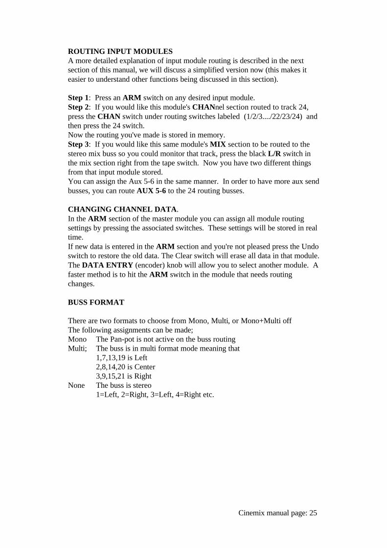
ROUTING INPUT MODULESA more detailed explanation of input module routing is described in the nextsection of this manual, we will discuss a simplified version now (this makes iteasier to understand other functions being discussed in this section).
Step 1: Press an ARM switch on any desired input module.Step 2: If you would like this module's CHANnel section routed to track 24,press the CHAN switch under routing switches labeled (1/2/3..../22/23/24) andthen press the 24 switch.Now the routing you've made is stored in memory.Step 3: If you would like this same module's MIX section to be routed to thestereo mix buss so you could monitor that track, press the black L/R switch inthe mix section right from the tape switch. Now you have two different thingsfrom that input module stored.You can assign the Aux 5-6 in the same manner. In order to have more aux sendbusses, you can route AUX 5-6 to the 24 routing busses.
CHANGING CHANNEL DATA.In the ARM section of the master module you can assign all module routingsettings by pressing the associated switches. These settings will be stored in realtime.If new data is entered in the ARM section and you're not pleased press the Undoswitch to restore the old data. The Clear switch will erase all data in that module.The DATA ENTRY (encoder) knob will allow you to select another module. Afaster method is to hit the ARM switch in the module that needs routingchanges.
BUSS FORMAT
There are two formats to choose from Mono, Multi, or Mono+Multi offThe following assignments can be made;Mono The Pan-pot is not active on the buss routingMulti; The buss is in multi format mode meaning that
1,7,13,19 is Left2,8,14,20 is Center3,9,15,21 is Right
None The buss is stereo1=Left, 2=Right, 3=Left, 4=Right etc.
Cinemix manual page: 25
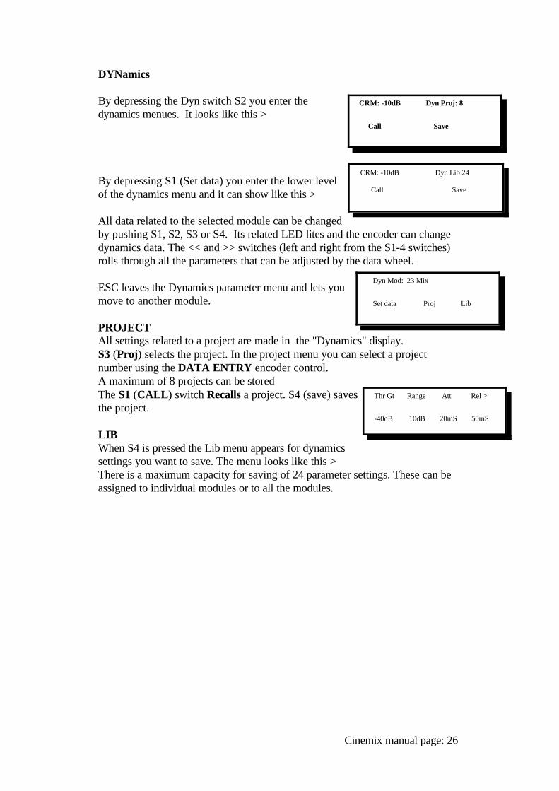
DYNamics
By depressing the Dyn switch S2 you enter thedynamics menues. It looks like this >
By depressing S1 (Set data) you enter the lower levelof the dynamics menu and it can show like this >
All data related to the selected module can be changedby pushing S1, S2, S3 or S4. Its related LED lites and the encoder can changedynamics data. The << and >> switches (left and right from the S1-4 switches) rolls through all the parameters that can be adjusted by the data wheel.
ESC leaves the Dynamics parameter menu and lets youmove to another module.
PROJECT All settings related to a project are made in the "Dynamics" display.S3 (Proj) selects the project. In the project menu you can select a projectnumber using the DATA ENTRY encoder control.A maximum of 8 projects can be storedThe S1 (CALL) switch Recalls a project. S4 (save) savesthe project.
LIBWhen S4 is pressed the Lib menu appears for dynamicssettings you want to save. The menu looks like this >There is a maximum capacity for saving of 24 parameter settings. These can beassigned to individual modules or to all the modules.
Cinemix manual page: 26
Dyn Mod: 23 Mix
Set data Proj Lib
Thr Gt Range Att Rel >
-40dB 10dB 20mS 50mS
CRM: -10dB Dyn Proj: 8
Call Save
CRM: -10dB Dyn Lib 24
Call Save
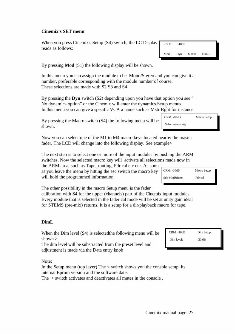
Cinemix's SET menu
When you press Cinemix's Setup (S4) switch, the LC Displayreads as follows:
By pressing Mod (S1) the following display will be shown.
In this menu you can assign the module to be Mono/Stereo and you can give it anumber, preferable corresponding with the module number of course.These selections are made with S2 S3 and S4
By pressing the Dyn switch (S2) depending upon you have that option you see “No dynamics option” or the Cinemix will enter the dynamics Setup menus.In this menu you can give a specific VCA a name such as Mstr Rght for instance.
By pressing the Macro switch (S4) the following menu will beshown.
Now you can select one of the M1 to M4 macro keys located nearby the masterfader. The LCD will change into the following display. See example>
The next step is to select one or more of the input modules by pushing the ARMswitches. Now the selected macro key will activate all selections made now inthe ARM area, such as Tape, routing, Fdr cal etc etc. As soonas you leave the menu by hitting the esc switch the macro keywill hold the programmed information.
The other possibility in the macro Setup menu is the fadercalibration with S4 for the upper (channels) part of the Cinemix input modules.Every module that is selected in the fader cal mode will be set at unity gain idealfor STEMS (pre-mix) returns. It is a setup for a dir/playback macro for tape.
DimL
When the Dim level (S4) is selectedthe following menu will beshown >The dim level will be substracted from the preset level andadjustment is made via the Data entry knob
Note:In the Setup menu (top layer) The < switch shows you the console setup, itsinternal Eprom version and the software date.The > switch activates and deactivates all mutes in the console .
Cinemix manual page: 27
CRM: -10dB
Mod. Dyn. Macro DimL
CRM: -10dB Macro Setup
Select macro key
CRM: -10dB Macro Setup
Sel; Mod&func. Fdr cal
CRM: -10dB Dim Setup
Dim level: -20 dB
AUTOMATION.Paragraph 12.0 PowerVca automation will outline the setup and use of D&R'sPowerVCA SMPTE based Automation. Since this section of Cinemix's manualis an insert, the page numbers will not be in sequence with the balance of thismanual. Optional PowerFade (D&R's moving fader automation) is available,however not discussed in this section
SETUP FOR AUTOMATED JOYSTICKS.
A unique feature in Cinemix are the two automated joysticks with its VirtualVision concept of showing you the position of the audio signal when controlledfrom D&R's PowerVCA automation.The "Set-up" switch serves actually the same purpose as theARM switches in the modules. As soon as the Setup switch is activated the following menuwill be shown>Depressing S1 (Buss) will display the following assignments.Main bussesGroup busses 1......8
9.....1617...24
Depresing S2 (Format) will display the following selection criteria.Left, RightSurround left, Surround RightLeft, Center, RightL,C,R mono SurroundL,C,R, Stereo srndoff
The third selection (S3) is the Sub Woofer. The level of the Sub Woofer can beadjusted between off and unity gain with a range of 63 dB in 0.5dB steps. toaccomodate any requested level.
ASSIGNING A CHANNEL TO A JOYSTICK
To assign a channel to a Joystick follow the next steps.
a. depress an ARM switch in a module and be sure that no master routing switchsuch as L/R, Center, SRND L/R, is assigned at that moment.
b. Select Joystick 1 or/off Joysttick 2.
Cinemix manual page: 28
CRM: -10dB Setup: JS 1
Buss Formt SW
The Virtual Vision matrix will show the panning ranges possible withcorresponding assignments.All movements will be memorized in PowerVCA together with mutes.
A host of possibilities are there to explore, It will take some time to manipulateall the possibilities Cinemix gives you in this area. Features like read and write onthe automation screen and Solo and Mute.
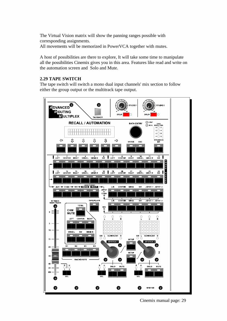
2.29 TAPE SWITCHThe tape switch will switch a mono dual input channels' mix section to followeither the group output or the multitrack tape output.
Cinemix manual page: 29
DUAL PATH MONO MODULEDESCRIPTION
3.0 DUAL PATH MONO MODULE - DESCRIPTIONCinemix's Dual Path mono input module is a basic input / output design wherebyall signal flow takes place from the microphone to the multitrack. Each dualpath mono module is shipped with PowerVCA Automation and a 13 segmentLED bargraph meter. The mic/line inputs are in the CHANNEL section of themodule while the TAPE machine outputs are in the MIX section.The following sections explain the many functions and features ofeach section of the dual path input module.
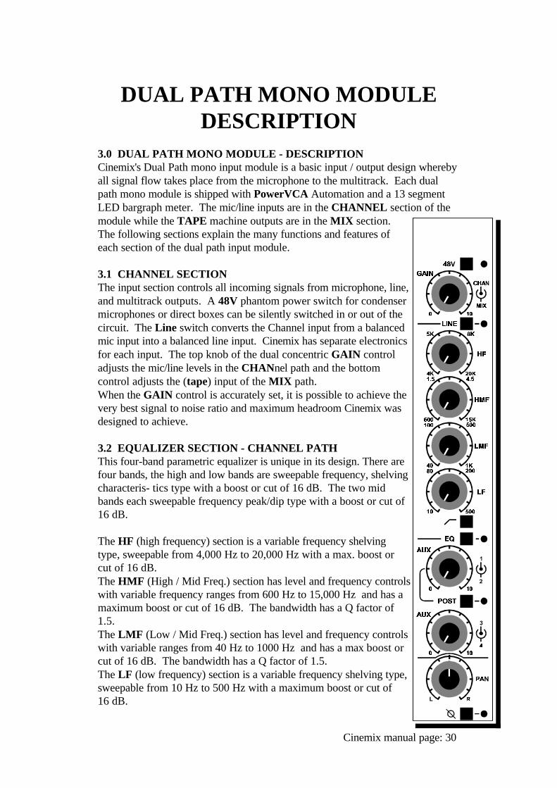
3.1 CHANNEL SECTIONThe input section controls all incoming signals from microphone, line,and multitrack outputs. A 48V phantom power switch for condensermicrophones or direct boxes can be silently switched in or out of thecircuit. The Line switch converts the Channel input from a balancedmic input into a balanced line input. Cinemix has separate electronicsfor each input. The top knob of the dual concentric GAIN controladjusts the mic/line levels in the CHANnel path and the bottomcontrol adjusts the (tape) input of the MIX path. When the GAIN control is accurately set, it is possible to achieve thevery best signal to noise ratio and maximum headroom Cinemix wasdesigned to achieve.
3.2 EQUALIZER SECTION - CHANNEL PATHThis four-band parametric equalizer is unique in its design. There arefour bands, the high and low bands are sweepable frequency, shelvingcharacteris- tics type with a boost or cut of 16 dB. The two midbands each sweepable frequency peak/dip type with a boost or cut of16 dB. The HF (high frequency) section is a variable frequency shelvingtype, sweepable from 4,000 Hz to 20,000 Hz with a max. boost orcut of 16 dB. The HMF (High / Mid Freq.) section has level and frequency controlswith variable frequency ranges from 600 Hz to 15,000 Hz and has amaximum boost or cut of 16 dB. The bandwidth has a Q factor of1.5. The LMF (Low / Mid Freq.) section has level and frequency controlswith variable ranges from 40 Hz to 1000 Hz and has a max boost orcut of 16 dB. The bandwidth has a Q factor of 1.5.The LF (low frequency) section is a variable frequency shelving type,sweepable from 10 Hz to 500 Hz with a maximum boost or cut of 16 dB.
Cinemix manual page: 30
All level controls are center detented making neutral positions easyto establish. All frequency ranges have been carefully selectedfollowing extensive examination of all types of music (and noise). Test comparisons of other equalizers helped the D&R design teamcreate an equalizer that sounds very musical , but at the same time,raising the standard in specs and sound quality. Noise anddistortion are kept to an absolute minimum. A High Pass Filter in / out switch is fitted to roll off the lowfrequencies at 100 Hertz.An equalizer on - off switch is fitted to allow easy comparisons.
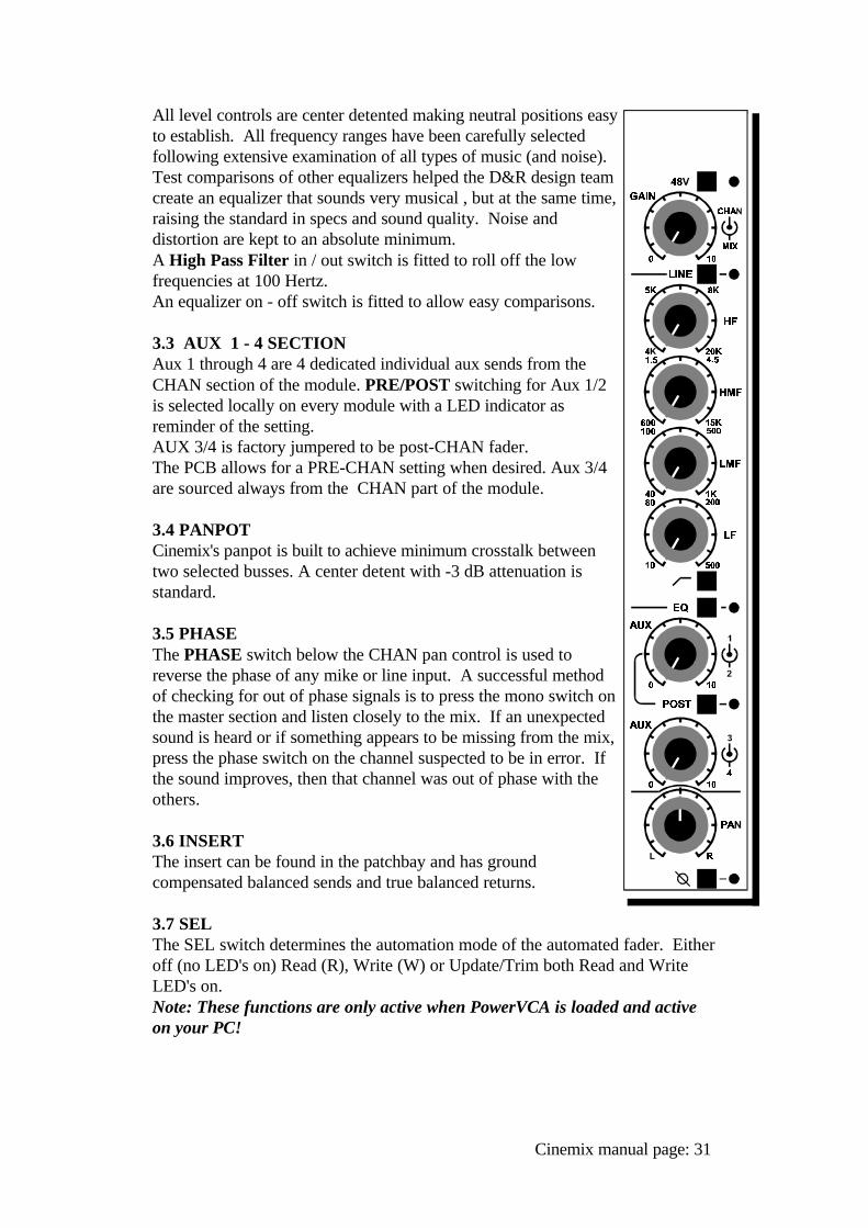
3.3 AUX 1 - 4 SECTIONAux 1 through 4 are 4 dedicated individual aux sends from theCHAN section of the module. PRE/POST switching for Aux 1/2is selected locally on every module with a LED indicator asreminder of the setting.AUX 3/4 is factory jumpered to be post-CHAN fader. The PCB allows for a PRE-CHAN setting when desired. Aux 3/4are sourced always from the CHAN part of the module.
3.4 PANPOTCinemix's panpot is built to achieve minimum crosstalk betweentwo selected busses. A center detent with -3 dB attenuation isstandard.
3.5 PHASEThe PHASE switch below the CHAN pan control is used toreverse the phase of any mike or line input. A successful methodof checking for out of phase signals is to press the mono switch onthe master section and listen closely to the mix. If an unexpectedsound is heard or if something appears to be missing from the mix,press the phase switch on the channel suspected to be in error. Ifthe sound improves, then that channel was out of phase with theothers.
3.6 INSERTThe insert can be found in the patchbay and has groundcompensated balanced sends and true balanced returns.
3.7 SELThe SEL switch determines the automation mode of the automated fader. Eitheroff (no LED's on) Read (R), Write (W) or Update/Trim both Read and WriteLED's on. Note: These functions are only active when PowerVCA is loaded and activeon your PC!
Cinemix manual page: 31
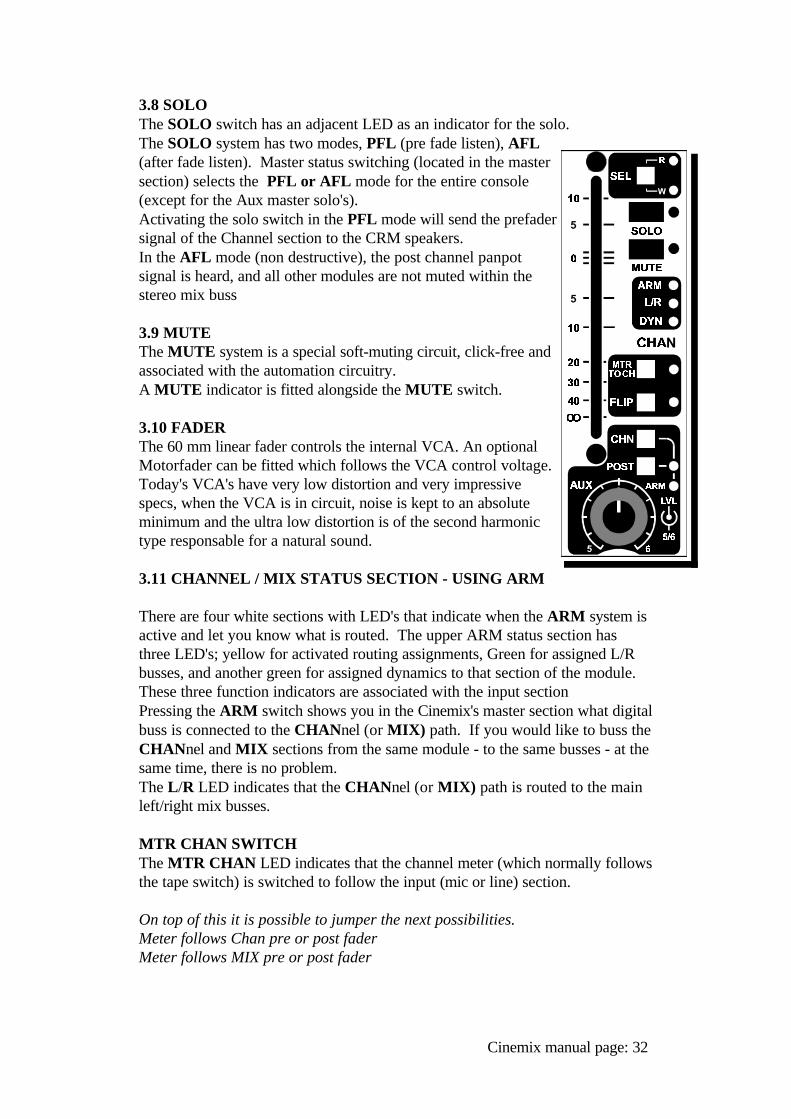
3.8 SOLOThe SOLO switch has an adjacent LED as an indicator for the solo. The SOLO system has two modes, PFL (pre fade listen), AFL(after fade listen). Master status switching (located in the mastersection) selects the PFL or AFL mode for the entire console(except for the Aux master solo's). Activating the solo switch in the PFL mode will send the prefadersignal of the Channel section to the CRM speakers. In the AFL mode (non destructive), the post channel panpotsignal is heard, and all other modules are not muted within thestereo mix buss
3.9 MUTEThe MUTE system is a special soft-muting circuit, click-free andassociated with the automation circuitry. A MUTE indicator is fitted alongside the MUTE switch.
3.10 FADERThe 60 mm linear fader controls the internal VCA. An optionalMotorfader can be fitted which follows the VCA control voltage.Today's VCA's have very low distortion and very impressivespecs, when the VCA is in circuit, noise is kept to an absoluteminimum and the ultra low distortion is of the second harmonictype responsable for a natural sound.
3.11 CHANNEL / MIX STATUS SECTION - USING ARM
There are four white sections with LED's that indicate when the ARM system isactive and let you know what is routed. The upper ARM status section hasthree LED's; yellow for activated routing assignments, Green for assigned L/Rbusses, and another green for assigned dynamics to that section of the module.These three function indicators are associated with the input section Pressing the ARM switch shows you in the Cinemix's master section what digitalbuss is connected to the CHANnel (or MIX) path. If you would like to buss theCHANnel and MIX sections from the same module - to the same busses - at thesame time, there is no problem. The L/R LED indicates that the CHANnel (or MIX) path is routed to the mainleft/right mix busses.
MTR CHAN SWITCHThe MTR CHAN LED indicates that the channel meter (which normally followsthe tape switch) is switched to follow the input (mic or line) section.
On top of this it is possible to jumper the next possibilities.Meter follows Chan pre or post faderMeter follows MIX pre or post fader
Cinemix manual page: 32
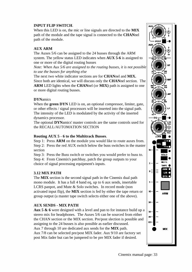
INPUT FLIP SWITCH.When this LED is on, the mic or line signals are directed to the MIXpath of the module and the tape signal is connected to the CHANnelpath of the module.
AUX ARMThe Auxes 5/6 can be assigned to the 24 busses through the ARMsystem. The yellow status LED indicates when AUX 5-6 is assigned toone or more of the digital routing bussesNote: When Aux 5/6 are assigned to the routing busses, it is not possibleto use the busses for anything elseThe next two white indicator sections are for CHANnel and MIX.Since both are identical, we will discuss only the CHANnel section. TheARM LED lights when the CHANnel (or MIX) path is assigned to oneor more digital routing busses.
DYNamicsWhen the green DYN LED is on, an optional compressor, limiter, gate,or other effects / signal processors will be inserted into the signal path.The intensity of the LED is modulated by the activity of the inserteddynamics processor. The optional DYNamics' master controls are the same controls used forthe RECALL/AUTOMATION SECTION
Routing AUX 5 - 6 to the Multitrack Busses.Step 1: Press ARM on the module you would like to route auxes from.Step 2: Press the red AUX switch below the buss switches in the mastersection Step 3: Press the Buss switch or switches you would prefer to buss to.Step 4: From Cinemix's patchbay, patch the group outputs to yourchoice of signal processing equipment's inputs.
3.12 MIX PATHThe MIX section is the second signal path in the Cinemix dual pathmono module. It has a full 4 band eq, up to 6 aux sends, insertableLCRS panpot, and Mute & Solo switches. In record mode (nonactivated input flip), the MIX section is fed by either the tape return orgroup output (a master tape switch selects either one of the above).
AUX SENDS - MIX PATH Aux 5 & 6 were designed with a level and pan to for instance build up astereo mix for headphones. The Auxes 5/6 can be sourced from eitherthe CHAN section or the MIX section. Pre/post slection is possible andassigning to the 24 busses is also possible as earlier discussed.Aux 7 through 10 are dedicated aux sends for the MIX path. Aux 7/8 can be selected pre/post MIX fader. Aux 9/10 are factory setpost Mix fader but can be jumpered to be pre MIX fader if desired.
Cinemix manual page: 33
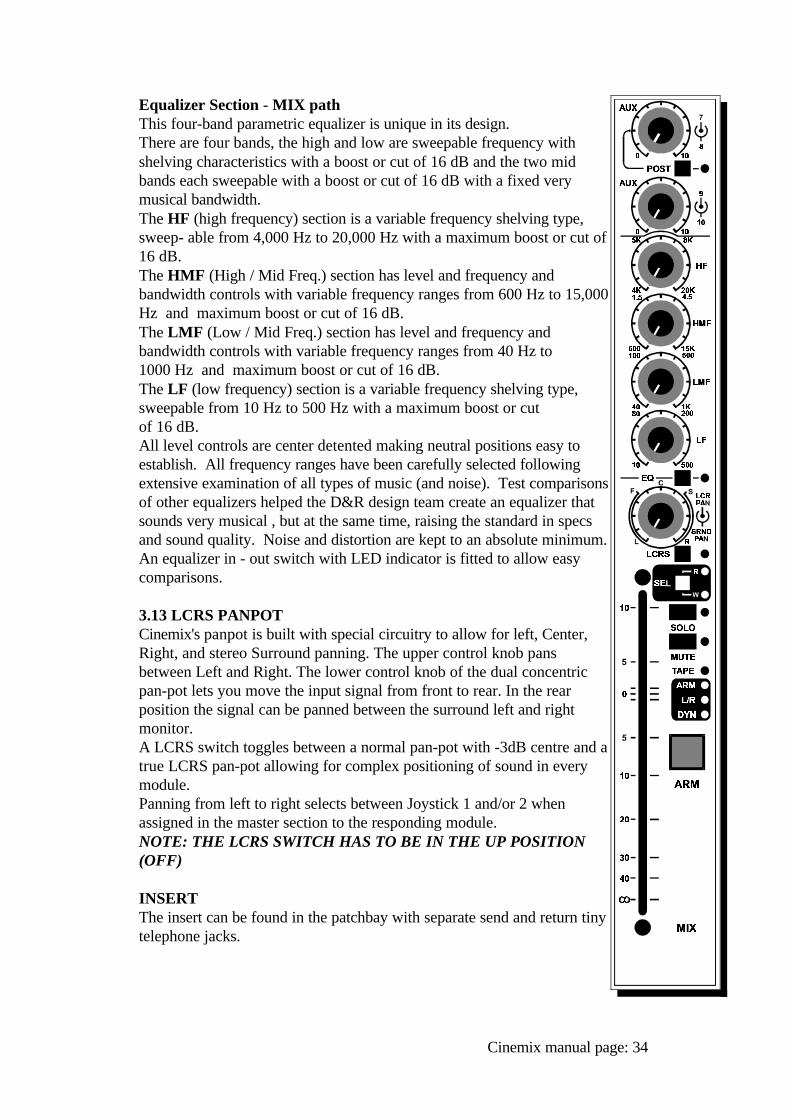
Equalizer Section - MIX pathThis four-band parametric equalizer is unique in its design. There are four bands, the high and low are sweepable frequency withshelving characteristics with a boost or cut of 16 dB and the two midbands each sweepable with a boost or cut of 16 dB with a fixed verymusical bandwidth.The HF (high frequency) section is a variable frequency shelving type,sweep- able from 4,000 Hz to 20,000 Hz with a maximum boost or cut of16 dB. The HMF (High / Mid Freq.) section has level and frequency andbandwidth controls with variable frequency ranges from 600 Hz to 15,000Hz and maximum boost or cut of 16 dB. The LMF (Low / Mid Freq.) section has level and frequency andbandwidth controls with variable frequency ranges from 40 Hz to 1000 Hz and maximum boost or cut of 16 dB. The LF (low frequency) section is a variable frequency shelving type,sweepable from 10 Hz to 500 Hz with a maximum boost or cut of 16 dB. All level controls are center detented making neutral positions easy toestablish. All frequency ranges have been carefully selected followingextensive examination of all types of music (and noise). Test comparisonsof other equalizers helped the D&R design team create an equalizer thatsounds very musical , but at the same time, raising the standard in specsand sound quality. Noise and distortion are kept to an absolute minimum. An equalizer in - out switch with LED indicator is fitted to allow easycomparisons.
3.13 LCRS PANPOTCinemix's panpot is built with special circuitry to allow for left, Center,Right, and stereo Surround panning. The upper control knob pansbetween Left and Right. The lower control knob of the dual concentricpan-pot lets you move the input signal from front to rear. In the rearposition the signal can be panned between the surround left and rightmonitor.A LCRS switch toggles between a normal pan-pot with -3dB centre and atrue LCRS pan-pot allowing for complex positioning of sound in everymodule.Panning from left to right selects between Joystick 1 and/or 2 whenassigned in the master section to the responding module.NOTE: THE LCRS SWITCH HAS TO BE IN THE UP POSITION(OFF)
INSERTThe insert can be found in the patchbay with separate send and return tinytelephone jacks.
Cinemix manual page: 34
SELThe SEL switch determines the automation mode of the automated fader.Either off (no LED's on) Read (R LED on), Write (W LED on) or Update/Trimboth Read and Write LED's on.
SOLOThe SOLO switch has an adjacent LED as an indicator for the solo being active. The SOLO system has two modes, PFL (pre fade listen), AFL (after fadelisten). Master status switching (located in the master section) selects the PFLor AFL mode for the entire console (except for the Aux master solo's). Activating the solo switch in the PFL mode will send the prefader signal of theChannel section to the CRM speakers. In the AFL mode (non destructive), thepost channel panpot signal is heard, and all other modules are not muted withinthe stereo mix buss
MUTEThe MUTE system is a special soft-muting circuit, click-free and associated withthe automation circuitry. A MUTE indicator is fitted alongside the MUTEswitch.
FADERThe 100 mm linear fader controls the internal VCA. An optional Motorfader canbe fitted which follows the VCA control voltage.Today's VCA's have very low distortion and very impressive specs, when theVCA is in circuit, noise is kept to an absolute minimum and the ultra lowdistortion is of the second harmonic type which is responsable for a naturalsound.
3.14 CHANNEL & MIX PATH INPUTS / OUTPUTSAll mic inputs are interfaced via female XLR 3 pin connectors located on themodule backpanels. All other module inputs and outputs are located in thepatchbay and accessible via 25 pin sub "D" connectors on the back of thepatchbay.
Cinemix manual page: 35
THE DUAL STEREO RETURNMODULE
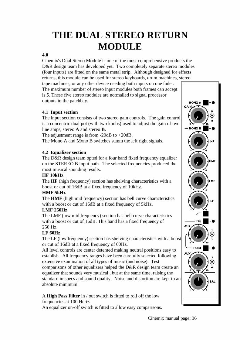
4.0Cinemix's Dual Stereo Module is one of the most comprehensive products theD&R design team has developed yet. Two completely separate stereo modules(four inputs) are fitted on the same metal strip. Although designed for effectsreturns, this module can be used for stereo keyboards, drum machines, stereotape machines, or any other device needing both inputs on one fader.The maximum number of stereo input modules both frames can acceptis 5. These five stereo modules are normalled to signal processoroutputs in the patchbay.
4.1 Input sectionThe input section consists of two stereo gain controls. The gain controlis a concentric dual pot (with two knobs) used to adjust the gain of twoline amps, stereo A and stereo B. The adjustment range is from -20dB to +20dB. The Mono A and Mono B switches summ the left right signals.
4.2 Equalizer sectionThe D&R design team opted for a four band fixed frequency equalizeron the STEREO B input path. The selected frequencies produced themost musical sounding results.HF 10kHz The HF (high frequency) section has shelving characteristics with aboost or cut of 16dB at a fixed frequency of 10kHz.HMF 5kHzThe HMF (high mid frequency) section has bell curve characteristicswith a boost or cut of 16dB at a fixed frequency of 5kHz.LMF 250HzThe LMF (low mid frequency) section has bell curve characteristicswith a boost or cut of 16dB. This band has a fixed frequency of 250 Hz.LF 60HzThe LF (low frequency) section has shelving characteristics with a boostor cut of 16dB at a fixed frequency of 60Hz.All level controls are center detented making neutral positions easy toestablish. All frequency ranges have been carefully selected followingextensive examination of all types of music (and noise). Testcomparisons of other equalizers helped the D&R design team create anequalizer that sounds very musical , but at the same time, raising thestandard in specs and sound quality. Noise and distortion are kept to anabsolute minimum.
A High Pass Filter in / out switch is fitted to roll off the lowfrequencies at 100 Hertz.An equalizer on-off switch is fitted to allow easy comparisons.
Cinemix manual page: 36
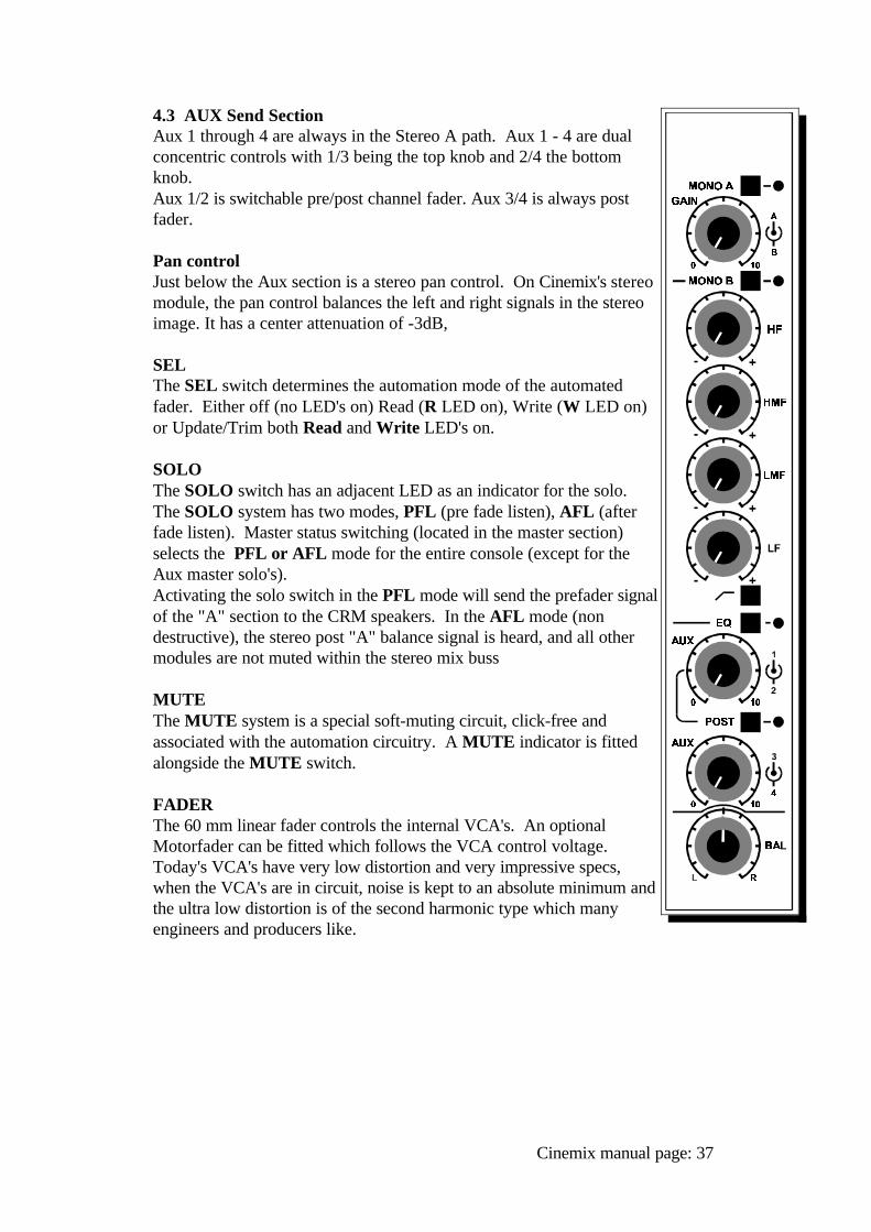
4.3 AUX Send SectionAux 1 through 4 are always in the Stereo A path. Aux 1 - 4 are dualconcentric controls with 1/3 being the top knob and 2/4 the bottomknob. Aux 1/2 is switchable pre/post channel fader. Aux 3/4 is always postfader.
Pan controlJust below the Aux section is a stereo pan control. On Cinemix's stereomodule, the pan control balances the left and right signals in the stereoimage. It has a center attenuation of -3dB,
SELThe SEL switch determines the automation mode of the automatedfader. Either off (no LED's on) Read (R LED on), Write (W LED on)or Update/Trim both Read and Write LED's on.
SOLOThe SOLO switch has an adjacent LED as an indicator for the solo. The SOLO system has two modes, PFL (pre fade listen), AFL (afterfade listen). Master status switching (located in the master section)selects the PFL or AFL mode for the entire console (except for theAux master solo's). Activating the solo switch in the PFL mode will send the prefader signalof the "A" section to the CRM speakers. In the AFL mode (nondestructive), the stereo post "A" balance signal is heard, and all othermodules are not muted within the stereo mix buss
MUTEThe MUTE system is a special soft-muting circuit, click-free andassociated with the automation circuitry. A MUTE indicator is fittedalongside the MUTE switch.
FADERThe 60 mm linear fader controls the internal VCA's. An optionalMotorfader can be fitted which follows the VCA control voltage.Today's VCA's have very low distortion and very impressive specs,when the VCA's are in circuit, noise is kept to an absolute minimum andthe ultra low distortion is of the second harmonic type which manyengineers and producers like.
Cinemix manual page: 37
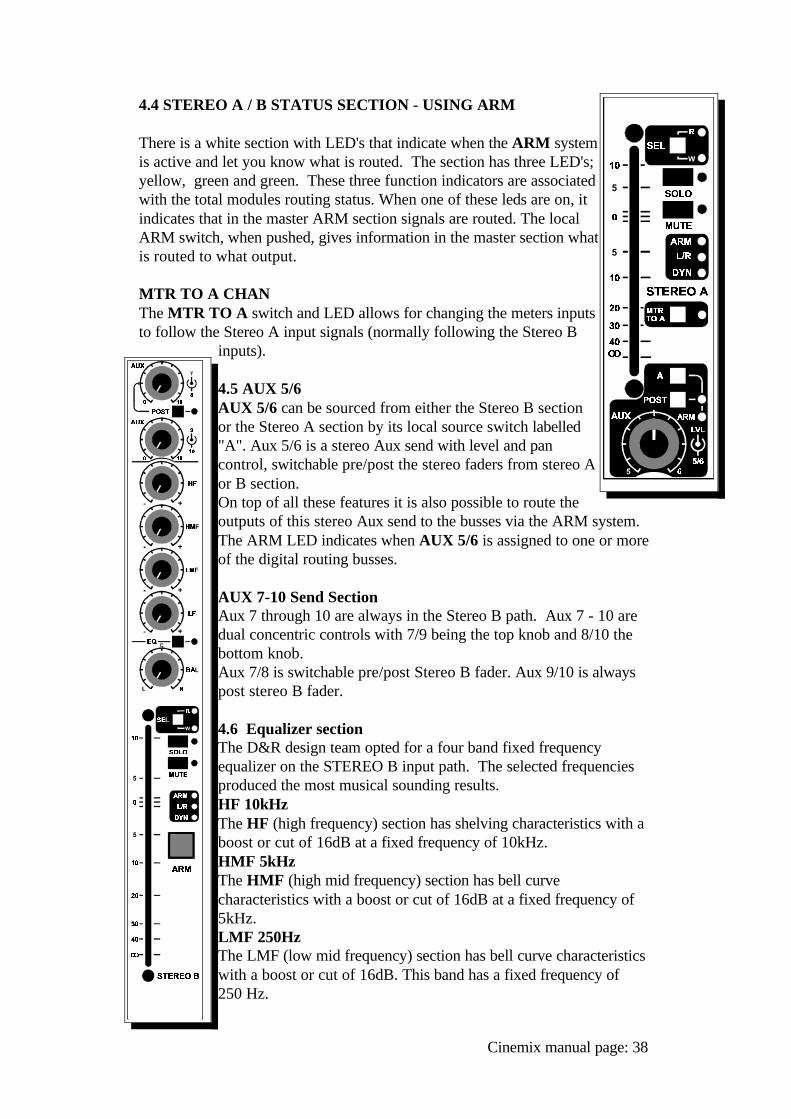
4.4 STEREO A / B STATUS SECTION - USING ARM
There is a white section with LED's that indicate when the ARM systemis active and let you know what is routed. The section has three LED's;yellow, green and green. These three function indicators are associatedwith the total modules routing status. When one of these leds are on, itindicates that in the master ARM section signals are routed. The localARM switch, when pushed, gives information in the master section whatis routed to what output.
MTR TO A CHANThe MTR TO A switch and LED allows for changing the meters inputsto follow the Stereo A input signals (normally following the Stereo B
inputs).
4.5 AUX 5/6AUX 5/6 can be sourced from either the Stereo B sectionor the Stereo A section by its local source switch labelled"A". Aux 5/6 is a stereo Aux send with level and pancontrol, switchable pre/post the stereo faders from stereo Aor B section.On top of all these features it is also possible to route theoutputs of this stereo Aux send to the busses via the ARM system.The ARM LED indicates when AUX 5/6 is assigned to one or moreof the digital routing busses.
AUX 7-10 Send SectionAux 7 through 10 are always in the Stereo B path. Aux 7 - 10 aredual concentric controls with 7/9 being the top knob and 8/10 thebottom knob. Aux 7/8 is switchable pre/post Stereo B fader. Aux 9/10 is alwayspost stereo B fader.
4.6 Equalizer sectionThe D&R design team opted for a four band fixed frequencyequalizer on the STEREO B input path. The selected frequenciesproduced the most musical sounding results.HF 10kHz The HF (high frequency) section has shelving characteristics with aboost or cut of 16dB at a fixed frequency of 10kHz.HMF 5kHzThe HMF (high mid frequency) section has bell curvecharacteristics with a boost or cut of 16dB at a fixed frequency of5kHz.LMF 250HzThe LMF (low mid frequency) section has bell curve characteristicswith a boost or cut of 16dB. This band has a fixed frequency of 250 Hz.
Cinemix manual page: 38
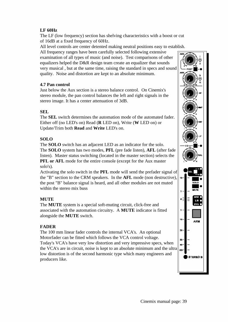
LF 60HzThe LF (low frequency) section has shelving characteristics with a boost or cutof 16dB at a fixed frequency of 60Hz.All level controls are center detented making neutral positions easy to establish.All frequency ranges have been carefully selected following extensiveexamination of all types of music (and noise). Test comparisons of otherequalizers helped the D&R design team create an equalizer that soundsvery musical , but at the same time, raising the standard in specs and soundquality. Noise and distortion are kept to an absolute minimum.
4.7 Pan controlJust below the Aux section is a stereo balance control. On Cinemix'sstereo module, the pan control balances the left and right signals in thestereo image. It has a center attenuation of 3dB.
SELThe SEL switch determines the automation mode of the automated fader.Either off (no LED's on) Read (R LED on), Write (W LED on) orUpdate/Trim both Read and Write LED's on.
SOLOThe SOLO switch has an adjacent LED as an indicator for the solo. The SOLO system has two modes, PFL (pre fade listen), AFL (after fadelisten). Master status switching (located in the master section) selects the PFL or AFL mode for the entire console (except for the Aux mastersolo's). Activating the solo switch in the PFL mode will send the prefader signal ofthe "B" section to the CRM speakers. In the AFL mode (non destructive),the post "B" balance signal is heard, and all other modules are not mutedwithin the stereo mix buss
MUTEThe MUTE system is a special soft-muting circuit, click-free andassociated with the automation circuitry. A MUTE indicator is fittedalongside the MUTE switch.
FADERThe 100 mm linear fader controls the internal VCA's. An optionalMotorfader can be fitted which follows the VCA control voltage.Today's VCA's have very low distortion and very impressive specs, whenthe VCA's are in circuit, noise is kept to an absolute minimum and the ultralow distortion is of the second harmonic type which many engineers andproducers like.
Cinemix manual page: 39
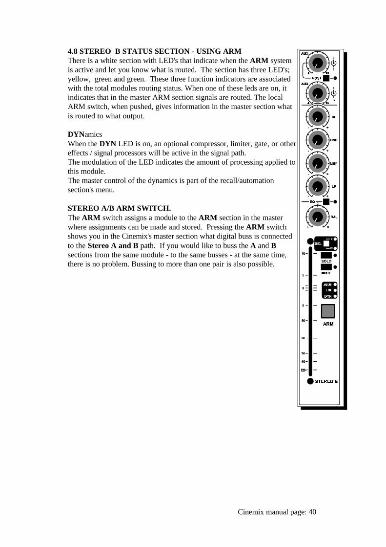
4.8 STEREO B STATUS SECTION - USING ARMThere is a white section with LED's that indicate when the ARM systemis active and let you know what is routed. The section has three LED's;yellow, green and green. These three function indicators are associatedwith the total modules routing status. When one of these leds are on, itindicates that in the master ARM section signals are routed. The localARM switch, when pushed, gives information in the master section whatis routed to what output.
DYNamicsWhen the DYN LED is on, an optional compressor, limiter, gate, or othereffects / signal processors will be active in the signal path. The modulation of the LED indicates the amount of processing applied tothis module. The master control of the dynamics is part of the recall/automationsection's menu.
STEREO A/B ARM SWITCH.The ARM switch assigns a module to the ARM section in the masterwhere assignments can be made and stored. Pressing the ARM switchshows you in the Cinemix's master section what digital buss is connectedto the Stereo A and B path. If you would like to buss the A and Bsections from the same module - to the same busses - at the same time,there is no problem. Bussing to more than one pair is also possible.
Cinemix manual page: 40
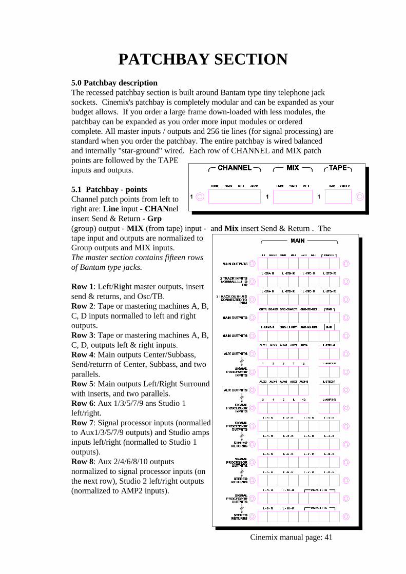
PATCHBAY SECTION5.0 Patchbay descriptionThe recessed patchbay section is built around Bantam type tiny telephone jacksockets. Cinemix's patchbay is completely modular and can be expanded as yourbudget allows. If you order a large frame down-loaded with less modules, thepatchbay can be expanded as you order more input modules or orderedcomplete. All master inputs / outputs and 256 tie lines (for signal processing) arestandard when you order the patchbay. The entire patchbay is wired balancedand internally "star-ground" wired. Each row of CHANNEL and MIX patchpoints are followed by the TAPEinputs and outputs.
5.1 Patchbay - pointsChannel patch points from left toright are: Line input - CHANnelinsert Send & Return - Grp(group) output - MIX (from tape) input - and Mix insert Send & Return . Thetape input and outputs are normalized toGroup outputs and MIX inputs. The master section contains fifteen rowsof Bantam type jacks.
Row 1: Left/Right master outputs, insertsend & returns, and Osc/TB.Row 2: Tape or mastering machines A, B,C, D inputs normalled to left and rightoutputs.Row 3: Tape or mastering machines A, B,C, D, outputs left & right inputs.Row 4: Main outputs Center/Subbass,Send/returrn of Center, Subbass, and twoparallels.Row 5: Main outputs Left/Right Surroundwith inserts, and two parallels.Row 6: Aux 1/3/5/7/9 ans Studio 1left/right.Row 7: Signal processor inputs (normalledto Aux1/3/5/7/9 outputs) and Studio ampsinputs left/right (normalled to Studio 1outputs).Row 8: Aux 2/4/6/8/10 outputsnormalized to signal processor inputs (onthe next row), Studio 2 left/right outputs(normalized to AMP2 inputs).
Cinemix manual page: 41
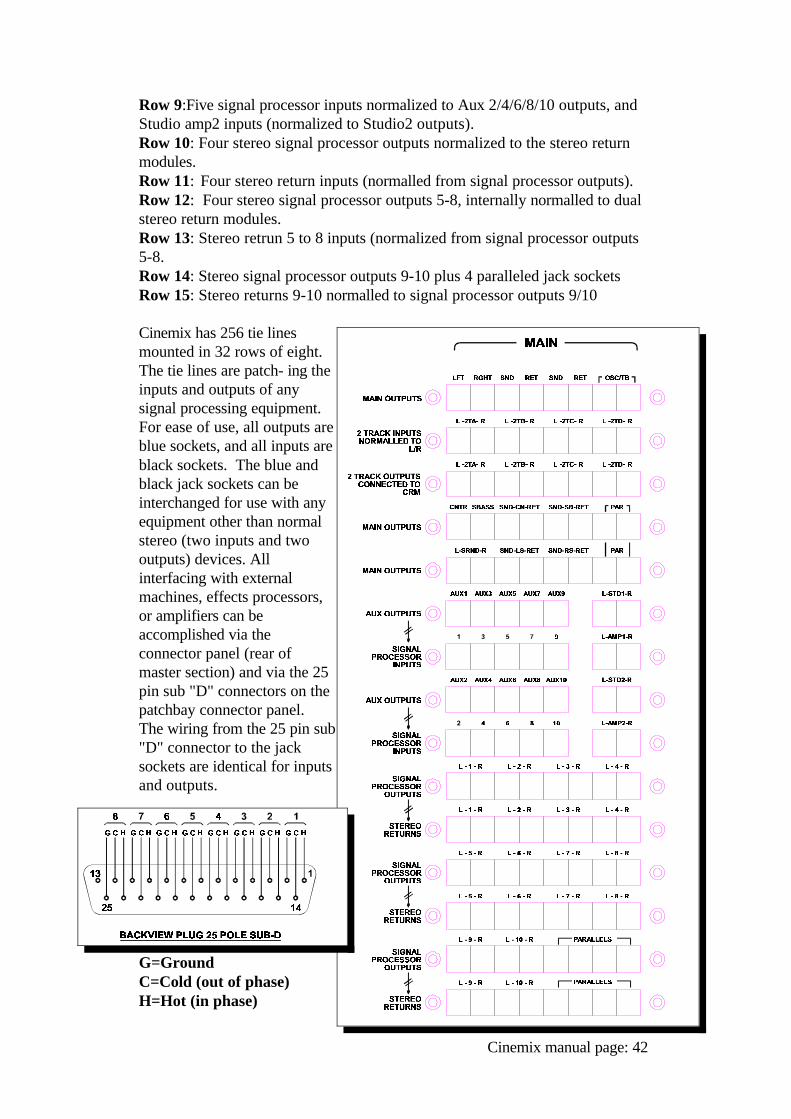
Row 9:Five signal processor inputs normalized to Aux 2/4/6/8/10 outputs, andStudio amp2 inputs (normalized to Studio2 outputs).Row 10: Four stereo signal processor outputs normalized to the stereo returnmodules.Row 11: Four stereo return inputs (normalled from signal processor outputs).Row 12: Four stereo signal processor outputs 5-8, internally normalled to dualstereo return modules.Row 13: Stereo retrun 5 to 8 inputs (normalized from signal processor outputs5-8.Row 14: Stereo signal processor outputs 9-10 plus 4 paralleled jack socketsRow 15: Stereo returns 9-10 normalled to signal processor outputs 9/10
Cinemix has 256 tie linesmounted in 32 rows of eight.The tie lines are patch- ing theinputs and outputs of anysignal processing equipment.For ease of use, all outputs areblue sockets, and all inputs areblack sockets. The blue andblack jack sockets can beinterchanged for use with anyequipment other than normalstereo (two inputs and twooutputs) devices. Allinterfacing with externalmachines, effects processors,or amplifiers can beaccomplished via theconnector panel (rear ofmaster section) and via the 25pin sub "D" connectors on thepatchbay connector panel.The wiring from the 25 pin sub"D" connector to the jacksockets are identical for inputsand outputs.
G=GroundC=Cold (out of phase)H=Hot (in phase)
Cinemix manual page: 42
INSTRUCTIONS FOROPERATION
6.0 Instructions for operationThe Cinemix is designed to be the perfect answer for Post Production, multitrackand MIDI studios. In order to get more familiar with the Cinemix, we shalldiscuss the entire recording process and divide it into five basic sequences.Sequence 1 through 4 are for the more conventional recording studios, andsequence 5 is for the MIDI studio.
1. The session - Recording from microphone or line input onto the multitrackmachine. This could be from one or more channels at a time.2. The playback - In this mode you would listen to what has been recorded onthe multitrack machine.
3. The overdub - Overdubbing is listening to already recorded tracks andrecording on empty tracks until all tracks are filled.4. The remix - Playing of all recorded tracks together with signal processingequipment and all that is necessary to create the final mixdown.5. The MIDI or Virtual Tracking - Programmed keyboards, drum machines,reverbs, effects, any singing and who knows what else, all at the same time directto your Dat Machine, two track master machine, or cassette deck.
6.1 The Tracking SessionThis is normally the beginning of a project. All input channels are placed in themic mode by leaving the line switch in the up position if the microphone input isto be used in this channel. Phantom powering is applied if necessary. The EQswitch should be in the up position unless you require EQ on that channel signal. The signal flows through the Channel fader and is available postfader to berouted by way of the ARM system feeding the input to your multitrack recorder. The LED bargraph reads the outgoing signal if the master Tape switch is in itsoff state.
Microphone / Line GainThe amount of gain required may depend on the type of microphone being used,the sound pressure level, and the distance between the sound source andmicrophone. When the line switch is activated, the same (upper) gain controlvaries the gain of the separate electronics for the balanced line input. The "phase" switch affects both mike and line inputs. After plugging in a mike orline signal, depress the channel solo switch alongside the channel fader you aresetting, set the solo status switch to pfl in the master section, then turn the gaincontrol (of that channel) clockwise until a "0" output level is reached on themaster ledbargraph/VU meters. Now slide up the channel fader to "0". Nowswitch the solo out. If the signal source gets louder or softer, it may be necessaryto re-check this setting. The volume will also fluctuate if you boost or cut the equalizer section.
Cinemix manual page: 43
Monitoring with the Cinemix series, you are able to monitor your multitrack byway of the separate MIX section. The MIX section of the dual path moduleallows you to have two usable inputs, both with EQ, both being able to send tothe aux. busses, both with their own volume control, panpots, mutes and solos,and able to be routed at the same time.
Multiple Modules Assigned to One or Two TracksWhen more than one microphone or line signal has to be recorded on a singletrack or in stereo on two tracks, a submix facility is required. This can be doneeasily on the CINEMIX by way of the internal subgroup amplifiers located onevery channel module and controlled by the ARM system. Simply route to one of the 24 subgroups by activating routing switches in themaster's ARM section on as many input modules as required. Decide on whichtrack you wish to record these signals and activate the related number. Thechannel metering will show the subgroup level which can be changed overall byapplying a PowerVCA's subgroup fader. In order to monitor these tracks on themodules, the master tape switch should be in the off position for monitoringpre-tape (console out) and in the On position for monitoring post-tape (mastertape switch lites).
Insert Channel / GroupFor high dynamic range types of inputs, a signal processor such as a compressor/ limiter can be inserted in the channel insert or in the MIX insert or activate theoptional Dynamics package.
Headphone (Cue) During recording it is essential that the talent hears an independent mix of whatthe engineer and producer are hearing. Headphone mixes are usually derivedfrom pre-fader auxiliaries. In the CINEMIX the Aux 1/2 and Aux 7/8 are ideal for this purpose. The best way to build a mix for the headphones is to have the MIX section of thedual line module feed Aux busses 7/8. When there is limited time to set up aheadphone mix, give the talent the CRM mix (L/R) in the Control Room sectionof the master modules and build up an independent headphone mix on aux. 7/8when time allows.
Effect SendsAll unused Aux. sends can be used to send signals to signal processors such asthe D&R "Qverb" 16 bit digital reverb, effects processors, and digital delays. The aux. sends are usually post-fader in order that the right balance betweenuntreated and treated signals is maintained however, it is possible to switch topre-fader.
Effects ReturnsIn the modern recording or MIDI studios of today, there is a demand for manyeffect returns and inputs for MIDI related gear.
Cinemix manual page: 44
For that reason D&R has designed the Cinemix with stereo effects returnmodules. See section 4.0 of this manual for a complete description of thismodule. Any unused channel or mix input can also be used for returning effects. Every channel can accept two returns with equalization and aux. sendcapabilities.
6.2 The Playback sessionMultitrack playback. The Cinemix gives you a convenient way of monitoringyour multitrack recorder. Switch your master TAPE switch to tape. Now the tape outputs are feeding the MIX path and you can adjust the amountof signal you desire and pan it within the stereo image. Auxiliary sends andequalization can be inserted in both signal paths whenever needed. Control over this processing is carried out by independent solo / mute systems inboth signal paths.
6.3 The Overdub sessionMultitrack synchronizing. Overdubbing is the process of building up a recordingtrack by track while listening to previously recorded tracks. The Cinemix has an in-line monitor for each track of the recorder making it easyto overdub. Connected to the MIX section of the dual path module, you selectthe master TAPE switch to follow the tape machine and do all your syncswitching from the tape machine or remote.The headphone mix is on the aux. send 1/2 or 7/8 busses. Aux 7 & 8 should gettheir signal from the MIX section. It is best to activate aux. 7/8 to pre fader atanytime you're using Aux 7/8 for a headphone mix.
6.4 The Remix sessionRemix is the process of combining all recorded tracks with (keyboards and drummachines for MIDI) signal processing and sending the mix to a two track mastermachine, DAT machine, or cassette recorder. On the dual path module yourmultitrack is connected to the MIX path. This routes the tape return to the MIXinput and leaves the mike/line inputs to the channel section of the module. Atthis point you can use either a mike or line input in the channel section which willfeed the stereo mix buss. This will give you two inputs per module in the finalmix. You can activate the desired EQ on the channel or Mix path. Theincoming signals can be routed to the stereo mix buss via the ARM system in thechannel assign section. VCA sub groups can be made up (as required) in thesame way as during recording. Aux sends 7 - 10 can get their signal from theMIX section and Aux 1 to 4 from the channel or MIX path with global pre/postswitching. Aux sends 5 / 6 get their signal from the channel section in the pre orpost fader position.
6.5 The MIDI or Virtual sessionIn most MIDI studios there will be an eight-track rather than a sixteen or twentyfour track tape machine. The majority of music production is programmed on asequencer using MIDI keyboards, sound modules, drum machines, or otherMIDI related equipment.
Cinemix manual page: 45
Therefore, you will only require tape tracks for vocals and those instruments notadequately reproduced on today's keyboards. If there is a multitrack recorder inthe MIDI studio, one of the tracks would be used to record a time code(SMPTE or MIDI code). This will allow your sequencer to keep keyboards,drum machines, and other MIDI equipment synchronized.
Cinemix was designed with the digital or analog multi-track and MIDI studio inmind. In today's medium to large MIDI studio, there is a need for as many as100 inputs to be used for everything from tape tracks to keyboards and drummachines. For this reason, the Cinemix, when fitted with both Dual Pathmodules and stereo return modules, can net over 106 inputs in the virtual tracksession or mix down.
6.6 Surround mixingThe Cinemix is the perfect mixer for laying down surround tracks.As already mentioned mixing down on 4 tracks (Pro-logic standard) is very easy.Use the Left/Right and Center outputs and the Surround left or right outputwhich both give the same signal when the Encoder is on.These signals are fed to the encoder unit by way of the 25 pole sub D connectorand the stereo outputs are fed back into the mixer for checking purposes.By depressing the Encoder Active switch the four output signals will be fed tothe external Encoder and not to the 4 CRM outputs anymore. At that very moment the stereo output of the Encoder is fed to the main CRMmonitors. The Center and Surround monitors will be muted at the same time. By activating the external Decoder( depress the DECODER ACTIVE switch),the encoded stereo signal will be decoded to full surround and fed toLeft/Center/Right and surround monitors for checking. When the Decoder Active switch is in its up position a full stereo signal (Lefttotal, Right total) will be heard and mono compatibility is checked with theMono switch.This easy set-up of surround sound coding and decoding makes a mix-down intosurround sound very easy to accomplish.
SIX CHANNEL 5.1 (DTS DOLBY DIGITAL)When mixing down in 5.1 all signals (Left/Center/Right/ Surround left/SurroundRight/ and Sub Bass) are mixed down onto a six channel recorder and monitoredback through the 6 Track input (eventually with the CP65 Dolby decoder).
Cinemix manual page: 46
7.0 Installation - Electrical
7.1 Local Electrical VoltageBefore connecting the Cinemix, check the AC supply voltage setting by lookingat the sticker on the back of the rack mount power supply. This should be115V for use in areas with an AC supply between 100V and 120V, and 230Vfor use in areas with an AC supply between 220V and 240V. Allow for a 30second wait between switching the Cinemix power supply(s) on oroff.The main fuse is a 6.3 amp fuse with a 250 volt rating (10 amp fuse in Americawith a 125 volt rating). After replacing a blown fuse with the correct size andrating, turn the power supply on and check the three LED indicators. If you arestill missing one or more of the power rails, turn off the power supply and call the D&R Technical Support Department.
NOTE: DO NOT REPLACE THE FUSE WITH ANY OTHER TYPE ASTHIS CAN BECOME A SAFETY HAZARD AND WILL VOID YOURWARRANTY.
7.2 Electrical WiringTo take full advantage of the excellent signal to noise ratio of the Cinemix, it isnecessary to read this part of the manual carefully.Hum, radio frequency interference, buzzes and instability are often caused byimproper wiring and poor grounding. All equipment using three wire acconnectors should have a ground lift adapter on each cable before plugging intothe ac outlet. In most cases, the incoming electrical ground is inadequate and adedicated ground system should be installed for the audio equipment. Yourlocal electric power company will provide you with all local electrical codes andsafety regulations.
There are some ground rules to follow. All signals in a recording studio arereferenced to ground. This ground must be clean and free of noise. A centralplace (central to all equipment) should be selected as the "central star groundpoint" and all grounds should terminate at this point. This point can be a solidmetal plate with at least 50 places to hookup all incoming grounds. This is commonly referred to as a "star ground system". In some instances electrical contractors will daisy chain ground connections inthe AC distribution system. This is not suitable for a studio. Ideally, run aseparate ground wire from each piece of equipment to the "central star groundpoint". The "central star ground point" should be connected to a pair of eight foot ground rods using larger (#10) wire than your equipment groundwires.
Cinemix manual page: 47
Separate and identify "clean" and "dirty" AC outlets. Use clean outlets for audioequipment and the dirty ones for lighting, air conditioning, cola machines etc.Do not intermix these two types of outlets. AC interference can be greatlyreduced by using an isolation transformer or some type of balanced ac powerdevice to power outlets. Ground this transformer directly to the "central starpoint".
After all equipment is connected to the ac power, check with a ohm meter orcontinuity tester to be sure of no possible chance of ground loops.
All equipment should be physically located as far as possible from the mainbreaker panel and should be totally isolated from the equipment rack and otherequipment so ground loops are avoided. Equipment can be mounted in woodrack rails to avoid ground loops or you can use "HUMFREES"
Now you can run a #12 stranded wire with jacket from each piece of equipmentto the "central star ground point". All ground wires should be the same lengthwith a tolerance of plus or minus 10% in order to have the same groundpotential everywhere. On the equipment ends of each ground wire you shouldsolder a round hole screw terminal.
Remove a chassis screw from each piece of equipment and file the paint in thatarea so it will make good contact when you connect the terminal. Next, connectthe ground wire terminal to each piece of equipment and connect each wire atthe other ends to the "central star ground point".
Cinemix manual page: 48
8.0 Installation - audio
8.1 Interface Power AmpsThe Cinemix in its standard configuration can interface with all availableequipment. Attention concerning the CRM output must be noted. This output delivers a nominal +4 dBu level which is sometimes too high forpower amps rated at 300mV sensitivity for full output. In some instances aninput attenuator at the power amp's input is required to reduce this +4 dBu levelby up to 12 dB. Contact the D&R Technical Support Department for details.NOTE: This alignment is imperative in order to avoid damage to the speakers,or in some cases, damage to the ears of the listener. 8.2 The Initial Hook-Up
First connect the rack-mounted power supplies to the console. All faders, monitors, and effect returns must be in the "down" or "off" position. In order to ensure the best signal to noise ratio for your system, the next stepsshould be performed in the order they are printed.
a. Connect the CRM outputs (located on the master section backplate) to theinputs of your control room speaker power amps. Now turn on the consolepower supplies and then turn your main power amp on and check for any hum,buzz, or interference. Slowly turn the CRM control clockwise until it is wideopen while listening for excessive noise. You should only hear a faint "hiss". Ifeverything is O.K., continue. If any hum or excess noise is present, stop and trydifferent ground and shielding arrangements until the system is clean. After checking the main power amp and speakers, check CRM 2 and 3.
b. Before making any other connections, move each monitor fader to the 0 dBposition with the master tape switch ON. Connect the multitrack cables to the25 pole sub-D connectors on the rear of the patchbay, then connect eachconnector on the tape output of your multitrack. Check for hum or noise aftereach track has been hooked up. "Hiss" will normally increase slightly with eachtrack. Connect the tape input jacks to the inputs of the multitrack. Carefullylisten for excessive noise or hum. If after hooking up an input or outputexcessive noise or hum is detected, stop and take corrective action beforeproceeding. Do not hook up all 16, 24, 32, or 48 tracks and then listen. You may need to rewire the entire cable harness to make the system clean.
c. Connect stereo tape recorders (inputs and outputs), stereo headphone amp,and all signal processors.
NOTE: MAKE SURE THAT YOU CHECK FOR HUM OR NOISE AS EACHINPUT OR OUTPUT IS CONNECTED.
Cinemix manual page: 49
8.3 Shields & Grounds of Equipment
The shield of any audio cable connection should be connected at one end only.If not, ground loops and high frequency cross-talk could result. Connect the shield as a general rule to the signal source (output) of anything. Inhigh RF areas it is wise to connect the other end of the shield through a 0.01microFarad capacitor. This will ground the RF but will not affect audiofrequencies.
When connecting balanced microphones, use two conductor shielded audiocable and connect both conductors and the shield at both ends. When connecting line level cables, use two conductor shielded cable and followthe instructions in the paragraph above. Remember, the shield is not consideredto be "ground" and it should only be connected at the output of any device.There are only a couple of exceptions to this rule, one is patch cords and theother is microphone cables. We realize that the correct interfacing of differentequipment is difficult, but once properly installed, the system will be clean andnoise free.
It is important to understand the term balanced. Balanced does not mean theinput or output is professional, the single factor that normally determineswhether something is professional is the level of the input or the output. +4 dBuis considered professional. -10 dBv is considered to be consumer levelsemi-professional. Because many semi-professional tape machines are built toprofessional specifications, D&R builds into the Cinemix console the ability tointerface with both levels.
Note: When checking your new Cinemix console for noise, you will notice thatthe console is extremely quiet without any external equipment hooked up. D&Ris not responsible for the noise you will experience when interfacing otherequipment. Since you are use to other consoles when first encountering a D&R,the lack of noise from your Cinemix makes you more aware of noise from otherequipment as you hook it up. D&R recommends using the highest qualityexternal equipment with the Cinemix. Because high quality sound must bemonitored with speakers and amps with extreme specs, D&R suggests usingonly the best amps to drive your speakers.
Cinemix manual page: 50
9.0 TROUBLE SHOOTING AND SERVICING
9.1 TroubleshootingIt is essential to study the signal flow chart in paragraph 12.0/13.0 carefully, onlythen can you hope to isolate problems. By tracing the signal from input tooutput jacks, it is possible to locate a problem. If for any reason you are unableto isolate a problem, contact the D&R Technical Support Department for advice. If the problem cannot be corrected over the phone, D&R will dispatch a replace-ment module the same day. Most problems can be found using logical thinkingand simply replacing socketed integrated circuits.
9.2 Removing a ModuleThe Cinemix is a complex piece of equipment and some understanding of itsinternal layout is necessary before removing a module. An input module haswiring to the LEDbar, master section and backplates. All of these wires must beremoved before withdrawing a module from the console.
Each module has computer grade connectors for ease of the disconnect. Turn off the power supply. It is often easier to loosen the modules positionedleft and right of the module under test. Remove the LEDbar wiring and removethe metal cover underneath the ledbar front which conceals the screws retainingthe module. It is now possible to remove the two module retaining screws andcarefully lift the module until the flatcable wiring can be unplugged. At this point extender cables (if ordered) can be connected. The master sectionscan be removed from the frame in the same way. Because of the many flatcables on the bottom of the master section, it is wise to remove all retainingscrews from all master sections. This will allow all the master modules to be moved slightly without unpluggingall the flat cables. A qualified service technician will be able to service themodules in this way.
9.3 Patchbay - servicingThe patchbay is fully modular and can be serviced after first removing thebackplates, then removing the cables attached to the card that needs servicing.The card can be removed after unscrewing two screws that push the patchpanelcard downwards. The card will still be connected to the internal star ground system which willneed to be unconnected before the card can be removed from the console.
Cinemix manual page: 51
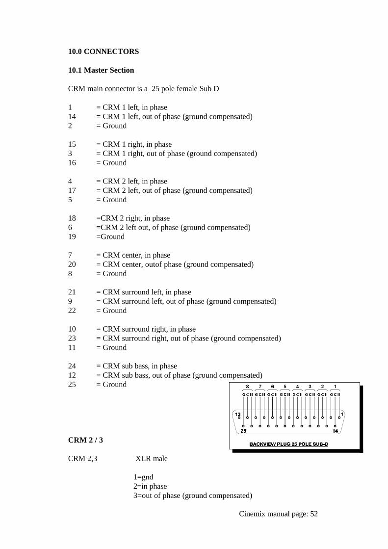
10.0 CONNECTORS
10.1 Master Section
CRM main connector is a 25 pole female Sub D
1 = CRM 1 left, in phase14 = CRM 1 left, out of phase (ground compensated)2 = Ground
15 = CRM 1 right, in phase3 = CRM 1 right, out of phase (ground compensated)16 = Ground
4 = CRM 2 left, in phase17 = CRM 2 left, out of phase (ground compensated)5 = Ground
18 =CRM 2 right, in phase6 =CRM 2 left out, of phase (ground compensated)19 =Ground
7 = CRM center, in phase20 = CRM center, outof phase (ground compensated)8 = Ground
21 = CRM surround left, in phase9 = CRM surround left, out of phase (ground compensated)22 = Ground
10 = CRM surround right, in phase23 = CRM surround right, out of phase (ground compensated)11 = Ground
24 = CRM sub bass, in phase12 = CRM sub bass, out of phase (ground compensated)25 = Ground
CRM 2 / 3
CRM 2,3 XLR male
1=gnd2=in phase3=out of phase (ground compensated)
Cinemix manual page: 52
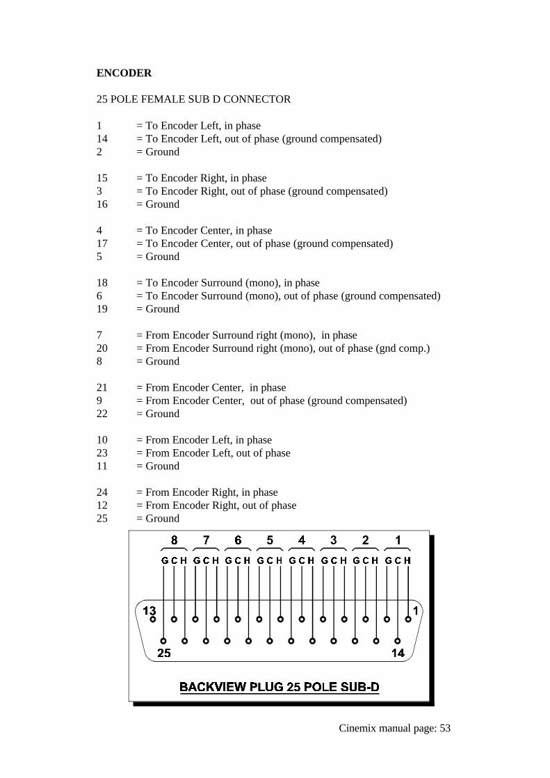
ENCODER
25 POLE FEMALE SUB D CONNECTOR
1 = To Encoder Left, in phase14 = To Encoder Left, out of phase (ground compensated)2 = Ground
15 = To Encoder Right, in phase3 = To Encoder Right, out of phase (ground compensated)16 = Ground
4 = To Encoder Center, in phase17 = To Encoder Center, out of phase (ground compensated)5 = Ground
18 = To Encoder Surround (mono), in phase6 = To Encoder Surround (mono), out of phase (ground compensated)19 = Ground
7 = From Encoder Surround right (mono), in phase20 = From Encoder Surround right (mono), out of phase (gnd comp.)8 = Ground
21 = From Encoder Center, in phase9 = From Encoder Center, out of phase (ground compensated)22 = Ground
10 = From Encoder Left, in phase23 = From Encoder Left, out of phase11 = Ground
24 = From Encoder Right, in phase12 = From Encoder Right, out of phase25 = Ground
Cinemix manual page: 53
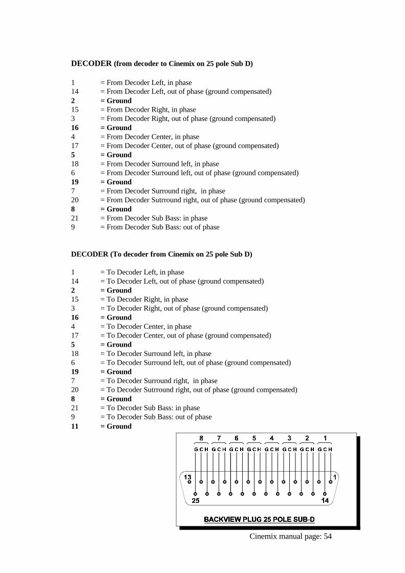
DECODER (from decoder to Cinemix on 25 pole Sub D)
1 = From Decoder Left, in phase14 = From Decoder Left, out of phase (ground compensated)2 = Ground15 = From Decoder Right, in phase3 = From Decoder Right, out of phase (ground compensated)16 = Ground4 = From Decoder Center, in phase17 = From Decoder Center, out of phase (ground compensated)5 = Ground18 = From Decoder Surround left, in phase6 = From Decoder Surround left, out of phase (ground compensated)19 = Ground7 = From Decoder Surround right, in phase20 = From Decoder Sutrround right, out of phase (ground compensated)8 = Ground21 = From Decoder Sub Bass: in phase9 = From Decoder Sub Bass: out of phase
DECODER (To decoder from Cinemix on 25 pole Sub D)
1 = To Decoder Left, in phase14 = To Decoder Left, out of phase (ground compensated)2 = Ground15 = To Decoder Right, in phase3 = To Decoder Right, out of phase (ground compensated)16 = Ground4 = To Decoder Center, in phase17 = To Decoder Center, out of phase (ground compensated)5 = Ground18 = To Decoder Surround left, in phase6 = To Decoder Surround left, out of phase (ground compensated)19 = Ground7 = To Decoder Surround right, in phase20 = To Decoder Sutrround right, out of phase (ground compensated)8 = Ground21 = To Decoder Sub Bass: in phase9 = To Decoder Sub Bass: out of phase11 = Ground
Cinemix manual page: 54
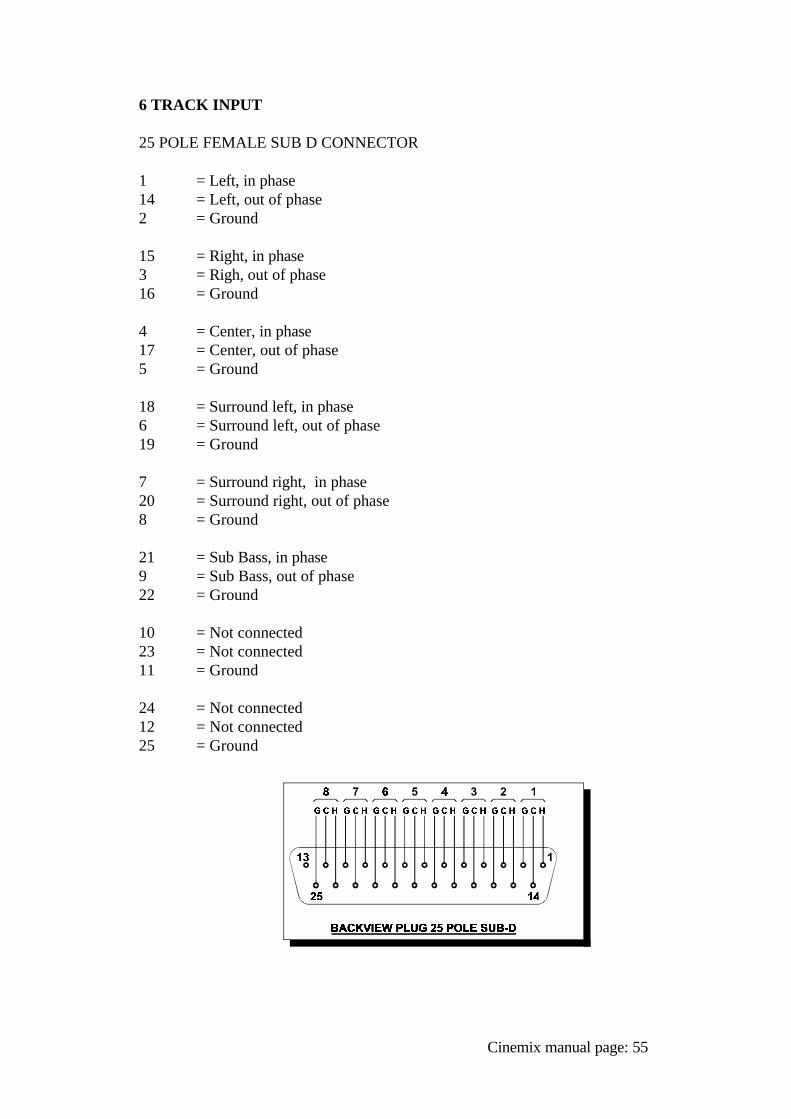
6 TRACK INPUT
25 POLE FEMALE SUB D CONNECTOR
1 = Left, in phase14 = Left, out of phase2 = Ground
15 = Right, in phase3 = Righ, out of phase16 = Ground
4 = Center, in phase17 = Center, out of phase5 = Ground
18 = Surround left, in phase6 = Surround left, out of phase19 = Ground
7 = Surround right, in phase20 = Surround right, out of phase8 = Ground
21 = Sub Bass, in phase9 = Sub Bass, out of phase22 = Ground
10 = Not connected23 = Not connected11 = Ground
24 = Not connected12 = Not connected25 = Ground
Cinemix manual page: 55
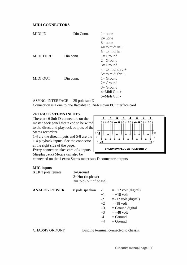
MIDI CONNECTORS
MIDI IN Din Conn. 1= none2= none3= none4= to midi in +5= to midi in -
MIDI THRU Din conn. 1= Ground2= Ground3= Ground4= to midi thru +5= to midi thru -
MIDI OUT Din conn. 1= Ground2= Ground3= Ground4=Midi Out +5=Midi Out -
ASYNC. INTERFACE 25 pole sub D Connection is a one to one flatcable to D&R's own PC interface card
24 TRACK STEMS INPUTSThere are 6 Sub-D connectors on themaster back panel that n eed to be wiredto the direct and playback outputs of theStems recorders. 1-4 are the direct inputs and 5-8 are the1-4 playback inputs. See the connectorat the right side of the page.Every connector takes care of 4 inputs(dir/playback) Meters can also beconnected on the 4 extra Stems meter sub-D connector outputs.
MIC inputs XLR 3 pole female 1=Ground
2=Hot (in phase)3=Cold (out of phase)
ANALOG POWER 8 pole speakon -1 = +12 volt (digital)+1 = +18 volt-2 = -12 volt (digital)+2 = -18 volt- 3 = Ground digital+3 = +48 volt-4 = Ground+4 = Ground
CHASSIS GROUND Binding terminal connected to chassis.
Cinemix manual page: 56
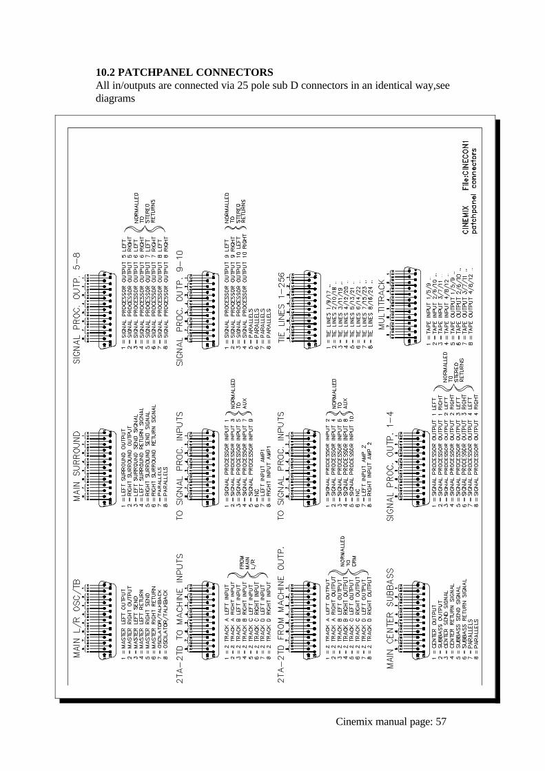
10.2 PATCHPANEL CONNECTORSAll in/outputs are connected via 25 pole sub D connectors in an identical way,seediagrams
Cinemix manual page: 57
11.0 SPECIFICATIONS
INPUTSMic inputs 2kOhm balanced -129 dBr input noise A weighted,
gain 84 dB
Line inputs 10kOhm balanced +/- 20dB gain control, max 34dB gain
Tape inputs 10kOhm balanced +4dBu, unbalanced -10dBV
Insert returns 10kOhm balanced 0 dBu
OUTPUTSTape outputs 47 Ohm +4dBu balanced /-10dBV unbalanced
(selectable).
Insert sends 47 Ohm ground compensated 0 dBu level.All other outputs 47 Ohm balanced +4dBu, max. +22dBu.
OVERALLHeadroom: no less than 22 dB
Frequency response: 10-200,000 Hz -2dB (VCA out)10-30,000 Hz -2dB (VCA in)
Harmonic distortion 0.007% (VCA out)0.016% (VCA in)
Noise 32 channels assigned -89dBr
Crosstalk No less than 90dBr
Cinemix manual page: 58
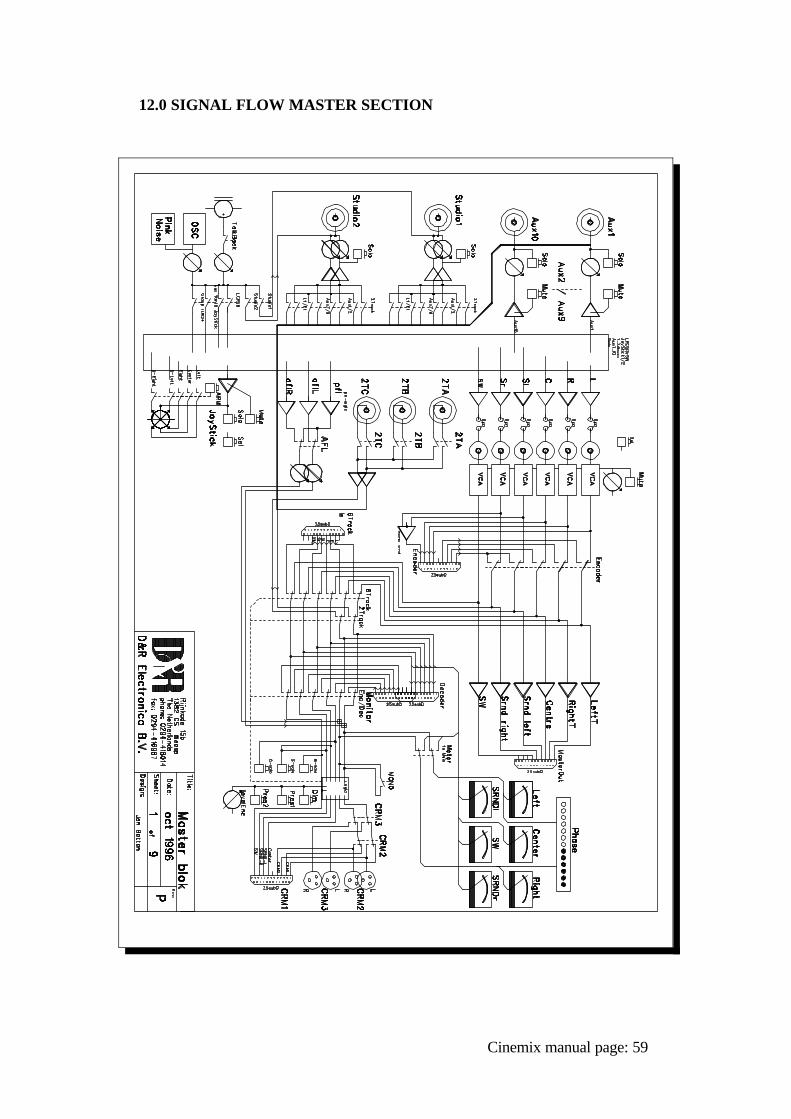
12.0 SIGNAL FLOW MASTER SECTION
Cinemix manual page: 59
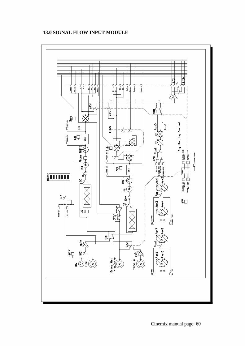
13.0 SIGNAL FLOW INPUT MODULE
Cinemix manual page: 60
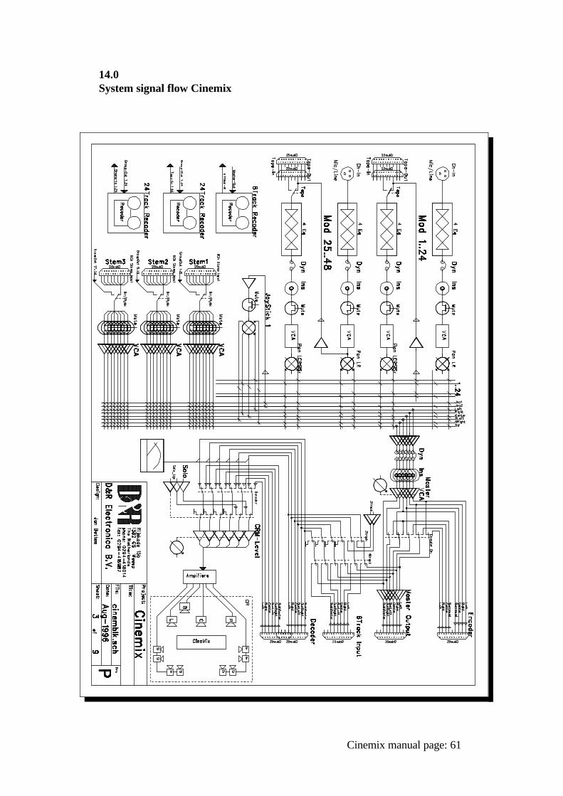
14.0 System signal flow Cinemix
Cinemix manual page: 61
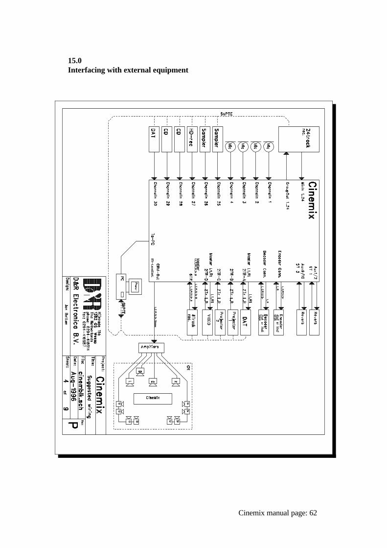
15.0Interfacing with external equipment
Cinemix manual page: 62
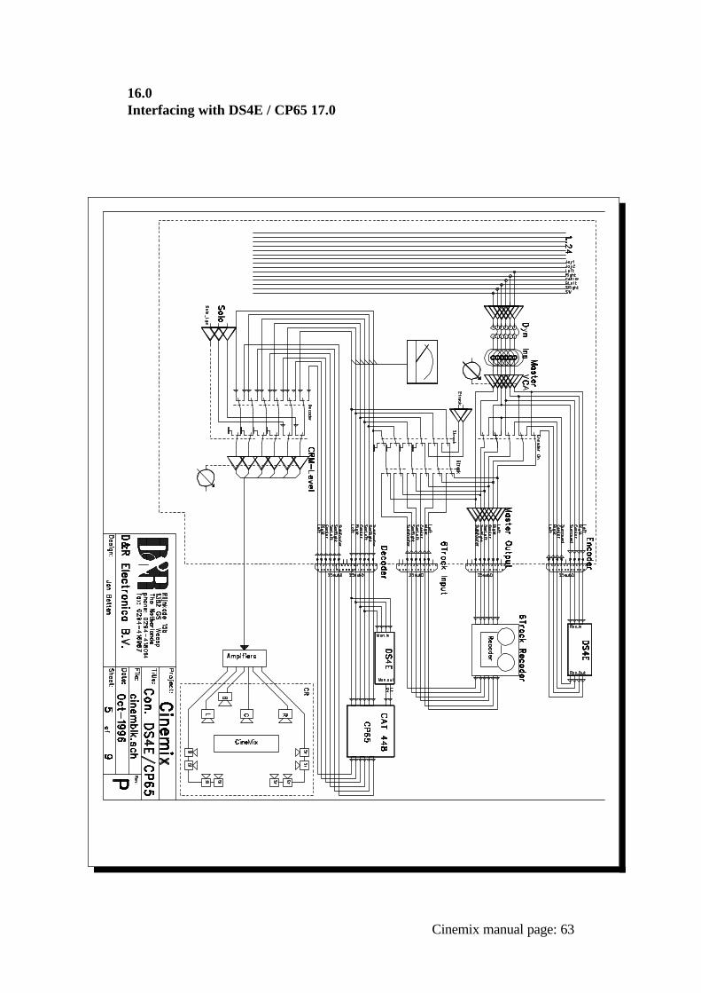
16.0Interfacing with DS4E / CP65 17.0
Cinemix manual page: 63

17.00Interfacing with "Dolby" SEU4 / SDU4
Cinemix manual page: 64
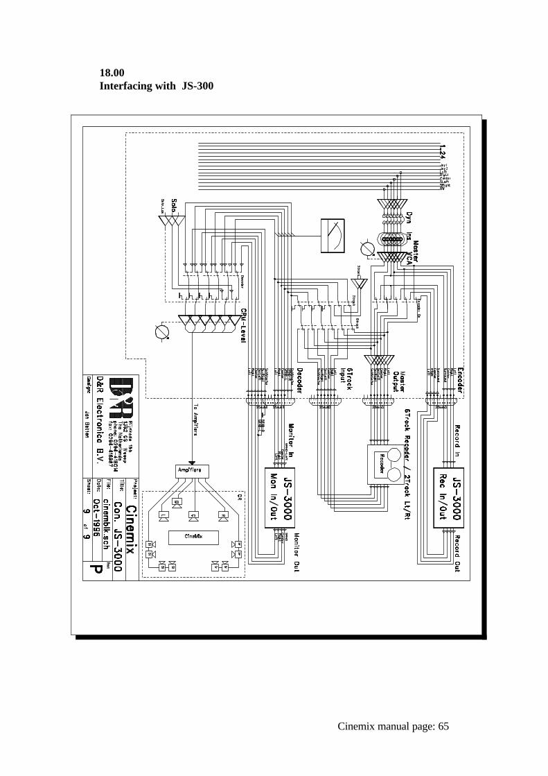
18.00Interfacing with JS-300
Cinemix manual page: 65
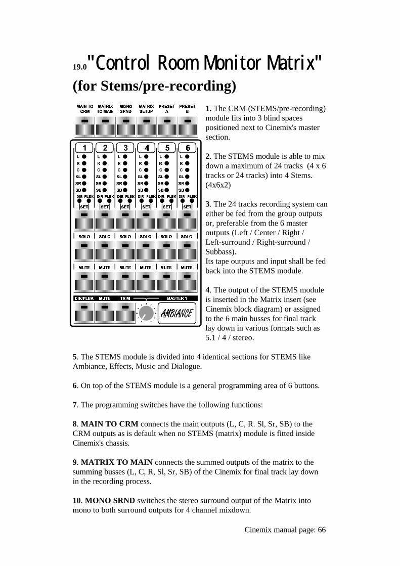
19.0"Control"Control Room Monitor Matrix" Room Monitor Matrix"(for Stems/pre-recording)
1. The CRM (STEMS/pre-recording)module fits into 3 blind spacespositioned next to Cinemix's mastersection.
2. The STEMS module is able to mixdown a maximum of 24 tracks (4 x 6tracks or 24 tracks) into 4 Stems.(4x6x2)
3. The 24 tracks recording system caneither be fed from the group outputsor, preferable from the 6 masteroutputs (Left / Center / Right /Left-surround / Right-surround /Subbass).Its tape outputs and input shall be fedback into the STEMS module.
4. The output of the STEMS moduleis inserted in the Matrix insert (seeCinemix block diagram) or assignedto the 6 main busses for final tracklay down in various formats such as5.1 / 4 / stereo.
5. The STEMS module is divided into 4 identical sections for STEMS likeAmbiance, Effects, Music and Dialogue.
6. On top of the STEMS module is a general programming area of 6 buttons.
7. The programming switches have the following functions:
8. MAIN TO CRM connects the main outputs (L, C, R. Sl, Sr, SB) to theCRM outputs as is default when no STEMS (matrix) module is fitted insideCinemix's chassis.
9. MATRIX TO MAIN connects the summed outputs of the matrix to thesumming busses (L, C, R, Sl, Sr, SB) of the Cinemix for final track lay downin the recording process.
10. MONO SRND switches the stereo surround output of the Matrix intomono to both surround outputs for 4 channel mixdown.
Cinemix manual page: 66
11. MATRIX SETUP puts the matrix in a programming mode. In this modeall inputs 1-24 can be individually assigned to one of the matrix outputs (L, C,R, Sl, Sr, SB) or to no output at all. Programming is done via the SET switchbelow the six assign LED's by stepping through all choices.
12. PRESET A and PRESET B is capable of putting the whole matrix in apreprogrammed mode instantly. Storing of a setup is done by holding downthe PRESET A or B switch by more than 3 seconds.
13. SET is located below the 6 assign LED's and switches between Direct,Playback and Toggle mode. In Toggle mode the LED of the SET switch is offand the channel can be switched by the master DIR/PLBK switch. Any combination of individual switching between direct (DIR) and playback(PLBK) and master DIR/PLBK switching can be programmed in this way. The SET switch is also to be used for MATRIX SETUP (see point 12)
14. SOLO puts one input (either Direct or Playback) on Cinemix's Solo buss,post TRIM control.
15. MUTE cancels the output of a track
16. DIR/PLBK switches all six outputs between direct and playback of allinput channels that are put in TOGGLE mode (SET led in switch is off).
17. MASTER MUTE mutes a whole group of 6 (complete STEMS)
18. TRIM activates the, otherwise fixed, master trim control for an overalladjustment of the complete 6 track (STEMS) level, when necessary.
Cinemix manual page: 67
19.1 INSTALLATION AND ALIGNMENT OF THE MATRIX MODULE
The STEMS/MATRIX module is built out of a number of horizontal PCB'swith very complex electronics, and we advice you to be very careful whenpositioning the module inside the Cinemix console.
1) Power down the console. Take out the 3 Blank modules positioned right of the Mastersection.
2) Connect the 10 wide flatcables to the corresponding 25pin Sub-Dconnectors on the backpanel of the Mastersection*.Connect the 16 pole flatcable coming from p.c. board "Matrix 7" (connector J3, remove jumpers) in the STEMS module, to connector J11 ("to prerecording") on p.c. board "Cinem 3" (starting from the left, this is the first p.c. board in themastersection).Now connect both 64 pole flatcables** of the console to the two 64 poleconnectors of the STEMS modules.
3) Check if everything is back on it's place again. Now power up the console.If there are signs of fire, explosions or any other things you normally wouldnot expect from a mixing console, call D&R HQ.
4) Switch "Matrix to CRM" on.Feed a balanced signal of +4dBu to input "Dir. 1" on the backpanel of theMastersection. With the switches DIR/PLBK on the frontpanel you can switch between theDirect and Playback inputs.Route the signal to the CRM Left, Right or Center output of theMastersection. The level of the input now has to trimmed with the trimpot on the p.c. boards"Matrix 5". These are the 2 p.c. boards at the bottom of the STEMS module.Both these boards are totally equal to eachother. The upper one is for the inputs 1-12 , the lower one is for the inputs 13-24. Totrim the level of input "Dir. 1" you have to adjust trimpot "Dir1/13" on theupper p.c. board.The input must be trimmed in such a way that the Master VU meters are at0dB with an input signal of +4dBu (***). Repeat this procedure for all remaining 23 "Dir." inputs and all 24 "Plbk"inputs.
5) After the installation of the STEMS module the communication between themodule and the mastersection must be checked. See if the SOLO andMATRIX TO MAIN functions are working properly.
Cinemix manual page: 68
NOTES:Depending if a new backpanel is supplied with retrofit kits for older consolesthe cables may already be connected to the backpanel. These are the flatcablesthat are lying on the bottom of the console. Several connectors are provided which all can be used.
*** This also applies for any external meters if used.
FUNCTIONS:
The STEMS/Monitoring Matrix Module is built up of 4 identical sections.Each section consists of 6 tracks, each track with a "Direct" and a"Playback"input.Each track has a dedicated "SET" , "SOLO" and "MUTE" switch.A master "Direct/Playback" switch and a master "Mute" switch are positionedat the bottom of each section together with the "Trim switch and pot.At the top of the module 6 masterfunction switches are positioned called"Main to CRM" , "Matrix to Main" , "Mono Surround" , "Matrix Setup" ,"Preset A" and "Preset B".
INDIVIDUAL FUNCTIONS PER TRACK:
Each track consists of a strip starting at the top with a square indicating thetrack number (1-24). Under the tracknumber 6 assign Led's are positioned which show if the outputof the track is routed to either the Left , Right , Center , Surround Left,Surround Right or Subbass master buses or CRM outputs.
- SET. The SET switch is located under the 6 assign led's. The SET switch enablesthe engineer to switch between the Direct and Playback signal. If the switch isput in Toggle mode (led in the switch off) the track output can be switchedbetween Direct and Playback using the master Dir/Playback switch positionedat the bottom of the section.The 3 following modes are programmed in sequence under the SET switch.
1)-Direct : the led in the SET switch and the red led at the left above theSET switch are lit.2)-Playback : the led in the SET switch and the green led at the right abovethe SET switch are lit.3)-Toggle : the led in the SET switch is off. The green or red led is on,depending of the position of the DIR/PLBK switch.
The SET switch is also used during the setup procedure of the module.When the module is in setup mode the SEL switch is used to route the output of the individual tracks to the 6 master outputs.
Cinemix manual page: 69
-SOLO When the SOLO switch is activated the corresponding input (either Direct or Playback) is put on the Cinemix's Solo buss, post TRIM control.
-MUTE Each individual track has it's own Mute switch which mutes theoutput of the track when activated.
Under the control switches of the individual tracks 3 more switches and atrimpotare positioned for control functions for the corresponding group of 6 inputs.
-DIR/PLBK The DIR/PLBK switch switches all 6 outputs between direct andplayback of all input channels that are put in TOGGLE mode (led in SETswitch off, see explanation SET switch).
-Master MUTE When activated this switch mutes all 6 tracks of thecorresponding group regardless the status of the individual mute settings.When the Master MUTE switch is deactivated again all settings will be thesame as before the Master MUTE was activated.
-TRIM When the TRIM switch is activated, the master TRIM control pot canbe used to adjust the overall level of the corresponding 6 tracks whennecessary.If the TRIM switch is deactivated the outputs are at a fixed level.
MODULE MASTER FUNCTIONS:
At the top of the module 6 master programming function switches are located.These switches are used to define and program the master status of thecomplete module.
-MAIN TO CRM When activated all main outputs (Left, Center, Right,Surround Left, Surround Right and Subbass) are connected to the CRMoutputs.
-MATRIX TO MAIN When the MATRIX TO MAIN switch is activated thesummed outputs of the matrix are connected to the master summing buses(L,C,R, Sl, Sr and SB) of the Cinemix. This feature can be used for finaltracklaydown in the recording process.
-MONO SRND With this switch the stereo surround outputs of the matrix canbe switched into mono signals to the Surround Left and Surround Rightoutputs.
Cinemix manual page: 70
-MATRIX SETUP the MATRIX SETUP switch puts the matrix module in aprogramming mode. In this mode all 24 individual tracks can be assigned toany of the 6 (L,C,R,Sl,Sr,SB) matrix outputs using the SET switches on eachtrack.
-PRESET A and PRESET B. The matrix module can be put in two different pre-programmed setups. When a setup has been programmed in the MATRIX SETUP mode, this setupcan be stored by pressing either PRESET A or PRESET B. When workingwith the module, either PRESET A or PRESET B must be activated.
If there is any question left do not hesitate to call our service department at0031 294 418014 or preferrably send a fax with your questions to 0031 294416987 an E-mail is also possible to [email protected]
19.2. ALIGNMENT OF VCA's:
a. Activate all the TRIM pots by activating the TRIM switch and position thepots in their mid position.b. Connect a voltmeter between pin 2 and 3 of VCA IC-8c. Now adjust with the small blue adjustment trimmer pots on PCB 5 thereading to be 0 volt.d. Repeat this procedure for IC-30 and all for all other VCA banks.e. Now the VCA's are controlled by the trimmer pots on the Matrix 4 PCBf. Now adjust the 4 trimmer pots on matrix 4 PCB (CPU) by adjusting thetrimmer pots on matrix 5, VCA-IC8 and VCA IC30. Measure between pin 2and 3.g. Now all VCA's are trimmed for 0 dB unity gain.h. Now connect a +4dBu signal on the dir/playback output and select via thefrontpanel switches an input (dir or playback) and assign this to an output of J3Matrix 7 PCB. The input can be trimmed with the trimmer pot near the VCA.The output should read 0dB with an input of +4dBu balanced.i. First trim the input level and check whether this signal can be assigned to alloutputs.j. Check if both inputs (DIR/PLAYBACK) are properly workingk. Check if the meter output has a level of 0 dBu.l. Check if SOLO works.m. Check if the VCA leveling works.n. Repeat this procedure for all 24 inputs.o. Check if the switches Main to CRM / Matrix to main / and Mono surroundwork properly.p. If there is only signal on Surround Left or Right and the Surround outputsare set to mono surround the output level should read -6dB.
Cinemix manual page: 71
20.0
Conformity statement according to ISO/IEC Nr 22 and EN 45014
Name Manufacturer D&R Electronica Weesp b.v.Addres manufacturer Rijnkade 15B,
1382 GS Weesp, The Netherlands
declares that this product
Name product CINEMIXModelnumber n.a.Produktoptions All
passed the following product specifications:
Security EN 60950: 1988 +A1, A2
EMC: CISPR-22: 1985 / EN 55022: 1988 class B (*)EN 50082-1: 1992IEC 801-2:1991 / prEN 55024-2:1992 - 3kV CD, 8kV ADIEC 801-3:1984 / prEN 55024-3:1991 - 3 V/mIEC 801-4:1988 / prEN 55024-4:1992 - 0.5kV signalcables, 1 kV powercables.
Extra information:
The product passed the specifications of the following regulations;
Low voltage 73 / 23 / EEGEMC-regulations 89 / 336 / EEG.
(*) The product is tested in a normal users environment.
Cinemix manual page: 72
21.0
PRODUCT SAFETY
This product is manufactured with the highest standards and is doublechecked in our quality control department for reliability in the"HIGH VOLTAGE" section.
CAUTIONNever remove any panels, or open this equipment. No user servicable parts inside.Equipment power supply must be grounded at all times.Only use this product as described, in user manual or brochure.Do not operate this equipment in high humidity or expose it to water or other liquids.Check the AC power supply cable to assure secure contact.Have your equipment checked yearly by a qualified dealer service center.Hazardous electrical shock can be avoided by carefully following the above rules.
EXTRA CAUTION FOR LIVE SOUND
Ground all equipment using the ground pin in the AC power supply cable.Never remove this pin. Ground loops should be eliminated only by use ofisolation transformers for all inputs and outputs. Replace any blown fuse withthe same type and rating only after equipment has been disconnected from ACpower. If problem persists, return equipment to qualified service technician
PLEASE READ THE FOLLOWING INFORMATION
Especially in sound equipment on stage the following information is essentialto know. An electrical shock is caused by voltage and current, actually it is the currentthat causes the shock. In practise the higher the voltage the higher the current will be and the higherthe shock.But there is another thing to consider and it is resistance. When the resistancein Ohms is high between two poles, the current will be low and vica versa.All three of these; voltage, current. and resistance are important in determiningthe effect of an electrical shock. However, the severity of a shock primarily determined by the amount ofcurrent flowing through a person. A person can feel a shock because the muscles in a body respond to electricalcurrent and because the heart is a muscle it can affect, when the current is highenough. Current can also be fatal when it causes the chest muscles to contractand stop breathing. At what potential is current dangereous. Well the first feeling of current is a tingle at 0.001 Amp of current. The currentbetween 0.1 Amp and 0.2 Amp is fatal.
Cinemix manual page: 73
Imagine that your home fuses of 20 Amp can handle 200 times more currentthan is necessary to kill. How does resistance affect the shock a person feels. Atypical resistance between one hand to the other in "dry" condition could wellover 100,000 Ohm.
If you are playing on stage your body is perspiring extensively and yourbody resistance is lowered by more than 50%. This is a situation in whichcurrent can easily flow. Current will flow when there is a difference in ground potential betweenequipment on stage and in the P.A. system. Please do check if there is anypotential between the housing of the mikes and the guitarsynth amps, whichwill be linked by your body on stage. Imagine, a guitar in your hand and yourlips close to the mike! A ground potential difference of above 10 volts is notunusual, in improperly wired buildings it can possibly be as high as 240 volts.
Allthough removing the ground wire sometimes cures a system hum, it willcreate a very hazardeous situation for the performing musician.Always earth all your equipment by the grounding pin in your mains plug.Hum loops should be only cured by proper wiring and isolation input/outputtransformers.
Replace fuses always with the same type and rating after the equipment hasbeen turned off and unplugged. If the fuse blows again you have an equipment failure, do not use it again andreturn it to your dealer for repair.
And last but not least be carefull not to touch a person being shocked as you,yourself could also be shocked. Once removed from the shock, have someone send for medical helpinmediately
Always keep the above mentionedinformation in mind when using electrically
powered equipment.
D&R Electronica Weesp b.v.Rijnkade 15B1382 GS, WEESPThe NetherlandsPhone: ++31-294-418 014FAX: ++31 294-416-987
Website: http:///www.d-r.nlE-mail: [email protected]
Cinemix manual page: 74
Dear Cinemix owner,
In this manual we have tried to give you an overview of all that the Cinemixhas to offer. If you have any questions, do not hesitate to contact us or theD&R USA customer support department. With the Cinemix series there is no limit to your creativity.We wish you many years of enjoyable mixing.
Best regards,
Duco de RijkPRESIDENT D&R, HOLLAND
We hope you find this manual useful and easy to understand. As always, weare open to any suggestions about this manual or any D&R products.
Cinemix manual page: 75