Embed Size (px)
Citation preview
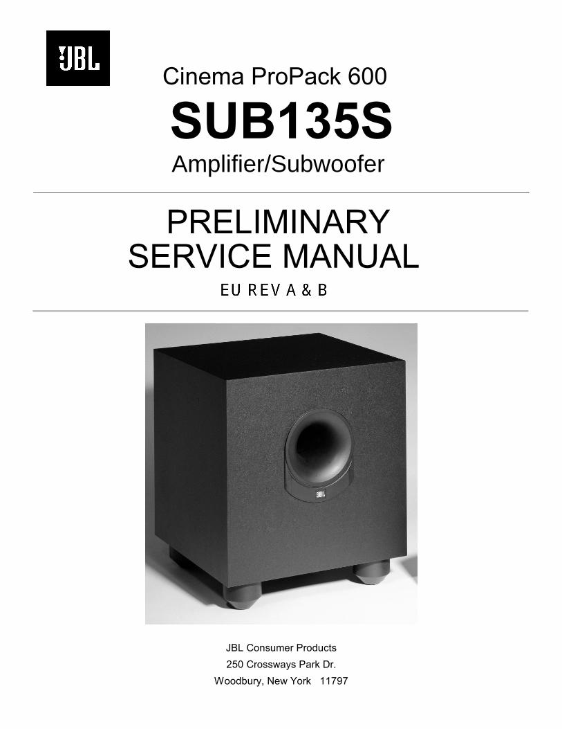
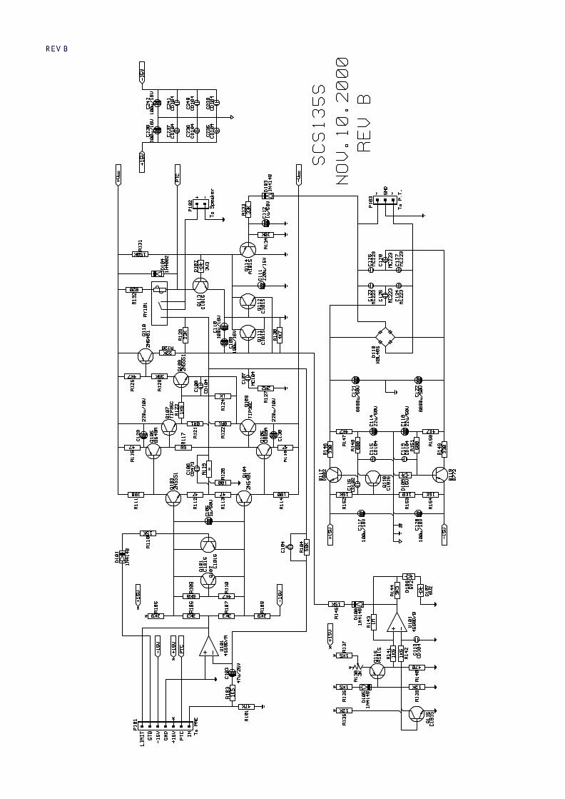
Cinema ProPack 600
SUB135SAmplifier/Subwoofer
PRELIMINARYSERVICE MANUAL
JBL Consumer Products
250 Crossways Park Dr.
Woodbury, New York 11797
Note: The SUB135S is part of the SCS135S system, which is partof the JBL Cinema Propack 600 system.
Satellite loudspeakers 135SAT are replacement-only; order JBLpart# SAT135.
- CONTENTS -
BASIC SPECIFICATIONS……………….……….……………….1DETAILED SPECIFICATIONS ……..…………………………..2OPERATION ………….…………………………….…………….3EXPLODED VIEW..………………………..……………….……...4TEST SET-UP AND PROCEDURE……..……………………….5PCB DRAWINGS…………… …..……………...………….……...6ELECTRICAL PARTS LIST …………… …..….………….……...8MECHANICAL PARTS LIST……………... .…………………….10SCHEMATICS ………..……………………………………………11
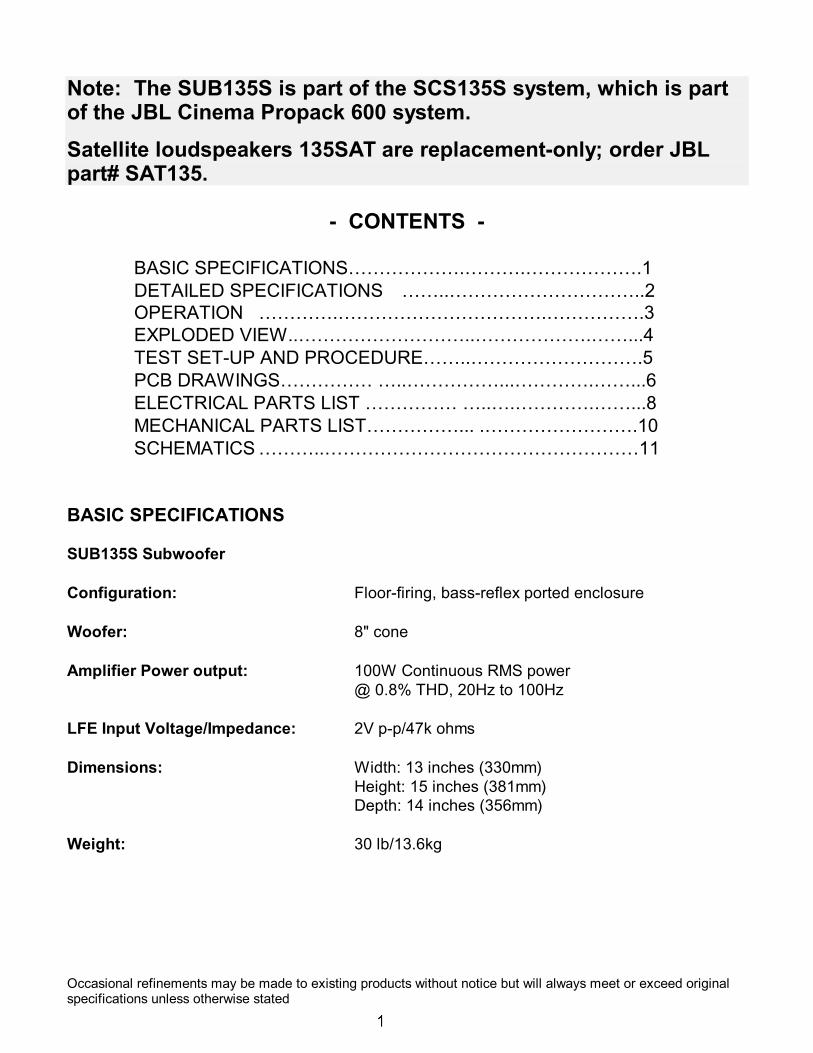
BASIC SPECIFICATIONS
SUB135S Subwoofer
Configuration: Floor-firing, bass-reflex ported enclosure
Woofer: 8" cone
Amplifier Power output: 100W Continuous RMS power@ 0.8% THD, 20Hz to 100Hz
LFE Input Voltage/Impedance: 2V p-p/47k ohms
Dimensions: Width: 13 inches (330mm)Height: 15 inches (381mm)Depth: 14 inches (356mm)
Weight: 30 lb/13.6kg
Occasional refinements may be made to existing products without notice but will always meet or exceed originalspecifications unless otherwise stated
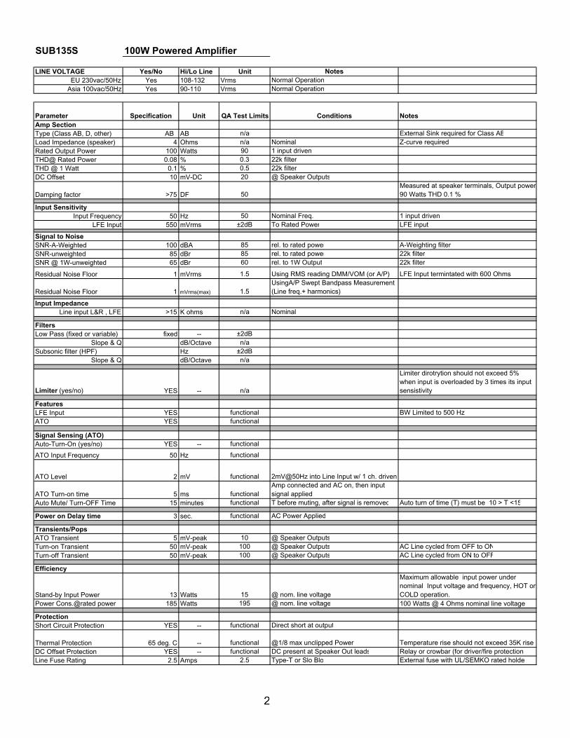
SUB135S 100W Powered Amplifier
LINE VOLTAGE Yes/No Hi/Lo Line Unit NotesEU 230vac/50Hz Yes 108-132 Vrms Normal Operation
Asia 100vac/50Hz Yes 90-110 Vrms Normal Operation
Parameter Specification Unit QA Test Limits Conditions NotesAmp SectionType (Class AB, D, other) AB AB n/a External Sink required for Class ABLoad Impedance (speaker) 4 Ohms n/a Nominal Z-curve requiredRated Output Power 100 Watts 90 1 input drivenTHD@ Rated Power 0.08 % 0.3 22k filterTHD @ 1 Watt 0.1 % 0.5 22k filterDC Offset 10 mV-DC 20 @ Speaker Outputs
Damping factor >75 DF 50Measured at speaker terminals, Output power90 Watts THD 0.1 %
Input SensitivityInput Frequency 50 Hz 50 Nominal Freq. 1 input driven
LFE Input 550 mVrms ±2dB To Rated Power LFE input
Signal to NoiseSNR-A-Weighted 100 dBA 85 rel. to rated power A-Weighting filterSNR-unweighted 85 dBr 85 rel. to rated power 22k filterSNR @ 1W-unweighted 65 dBr 60 rel. to 1W Output 22k filter
Residual Noise Floor 1 mVrms 1.5 Using RMS reading DMM/VOM (or A/P) LFE Input termintated with 600 Ohms
Residual Noise Floor 1 mVrms(max) 1.5UsingA/P Swept Bandpass Measurement (Line freq.+ harmonics)
Input ImpedanceLine input L&R , LFE >15 K ohms n/a Nominal
FiltersLow Pass (fixed or variable) fixed -- ±2dB
Slope & Q dB/Octave n/aSubsonic filter (HPF) Hz ±2dB
Slope & Q dB/Octave n/a
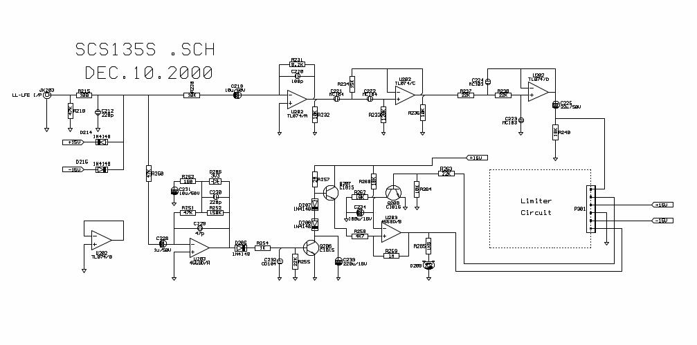
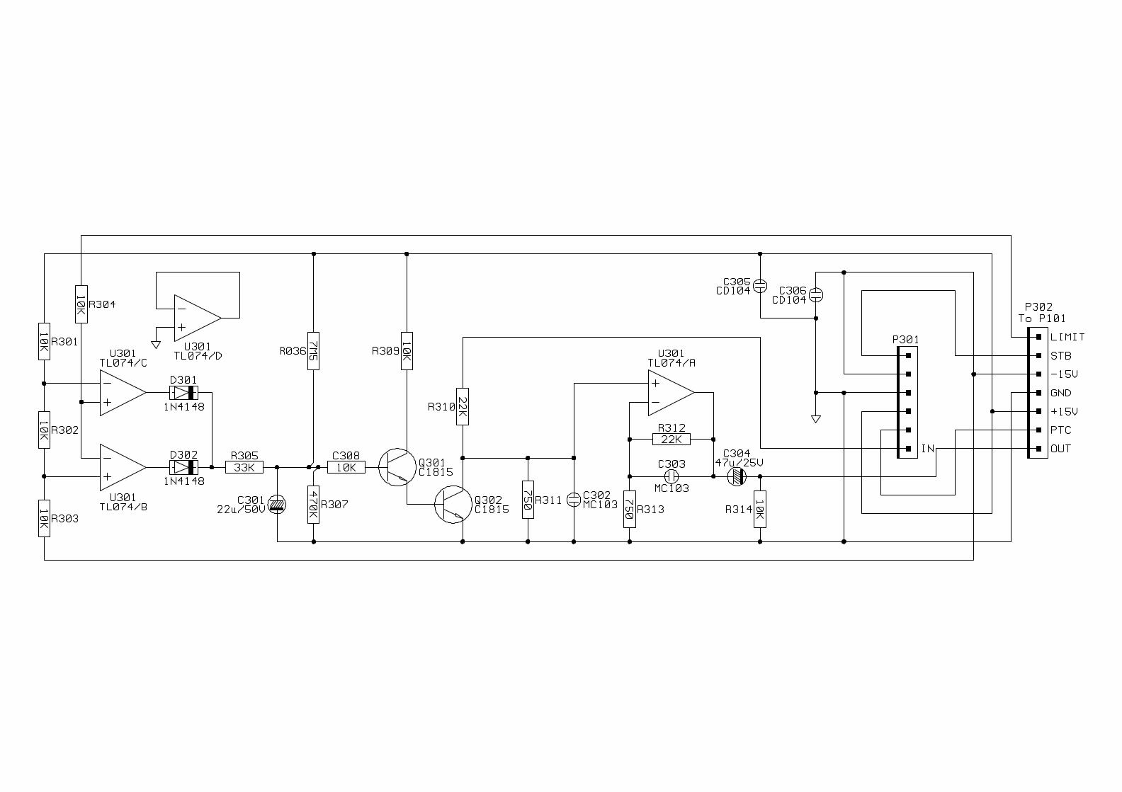
Limiter (yes/no) YES -- n/a
Limiter dirotrytion should not exceed 5% when input is overloaded by 3 times its input sensistivity
FeaturesLFE Input YES functional BW Limited to 500 HzATO YES functional
Signal Sensing (ATO)Auto-Turn-On (yes/no) YES -- functional
ATO Input Frequency 50 Hz functional
ATO Level 2 mV functional 2mV@50Hz into Line Input w/ 1 ch. driven
ATO Turn-on time 5 ms functionalAmp connected and AC on, then input signal applied
Auto Mute/ Turn-OFF Time 15 minutes functional T before muting, after signal is removed Auto turn of time (T) must be 10 > T <15
Power on Delay time 3 sec. functional AC Power Applied
Transients/PopsATO Transient 5 mV-peak 10 @ Speaker OutputsTurn-on Transient 50 mV-peak 100 @ Speaker Outputs AC Line cycled from OFF to ONTurn-off Transient 50 mV-peak 100 @ Speaker Outputs AC Line cycled from ON to OFF
Efficiency
Stand-by Input Power 13 Watts 15 @ nom. line voltage
Maximum allowable input power under nominal Input voltage and frequency, HOT or COLD operation.
Power Cons.@rated power 185 Watts 195 @ nom. line voltage 100 Watts @ 4 Ohms nominal line voltage
ProtectionShort Circuit Protection YES -- functional Direct short at output
Thermal Protection 65 deg. C -- functional @1/8 max unclipped Power Temperature rise should not exceed 35K riseDC Offset Protection YES -- functional DC present at Speaker Out leads Relay or crowbar (for driver/fire protection)Line Fuse Rating 2.5 Amps 2.5 Type-T or Slo Blo External fuse with UL/SEMKO rated holder
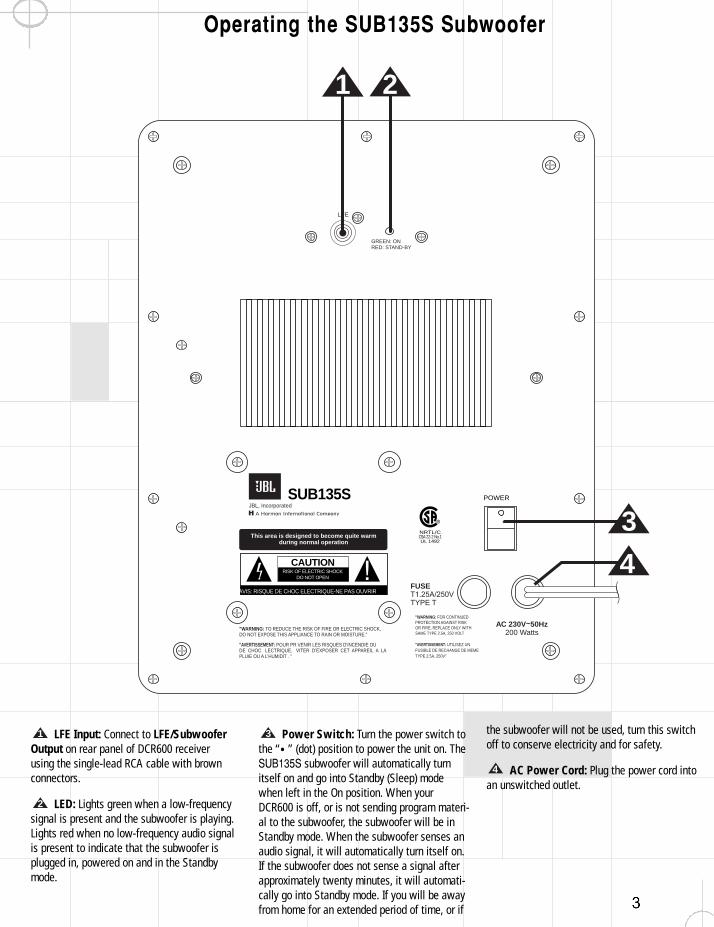
Operating the SUB135S Subwoofer
LFE Input: Connect to LFE/SubwooferOutput on rear panel of DCR600 receiverusing the single-lead RCA cable with brownconnectors.
LED: Lights green when a low-frequencysignal is present and the subwoofer is playing.Lights red when no low-frequency audio signalis present to indicate that the subwoofer isplugged in, powered on and in the Standbymode.
Power Switch: Turn the power switch tothe “•” (dot) position to power the unit on. TheSUB135S subwoofer will automatically turnitself on and go into Standby (Sleep) modewhen left in the On position. When yourDCR600 is off, or is not sending program materi-al to the subwoofer, the subwoofer will be inStandby mode. When the subwoofer senses anaudio signal, it will automatically turn itself on.If the subwoofer does not sense a signal afterapproximately twenty minutes, it will automati-cally go into Standby mode. If you will be awayfrom home for an extended period of time, or if
the subwoofer will not be used, turn this switchoff to conserve electricity and for safety.
AC Power Cord: Plug the power cord intoan unswitched outlet.
4
3
2
1
LFE
GREEN: ONRED: STAND-BY
SUB135S
CAUTIONRISK OF ELECTRIC SHOCK
DO NOT OPEN
"WARNING: TO REDUCE THE RISK OF FIRE OR ELECTRIC SHOCK, DO NOT EXPOSE THIS APPLIANCE TO RAIN OR MOISTURE."
"AVERTISSEMENT: POUR PR VENIR LES RISQUES D’INCENDIE OU DE CHOC LECTRIQUE, VITER D’EXPOSER CET APPAREIL A LA PLUIE OU A L’HUMIDIT . "
"WARNING: FOR CONTINUED PROTECTION AGAINST RISK OR FIRE, REPLACE ONLY WITH SAME TYPE 2.5A, 250 VOLT
"AVERTISSEMENT: UTILISEZ UN FUSIBLE DE RECHANGE DE MEME TYPE 2.5A, 250V"
NRTL/CCSA 22-2 No.1UL 1492
AVIS: RISQUE DE CHOC ELECTRIQUE-NE PAS OUVRIR
POWER
FUSET1.25A/250VTYPE T
AC 230V~50Hz200 Watts
This area is designed to become quite warmduring normal operation
JBL, Incorporated
1 2
3
4
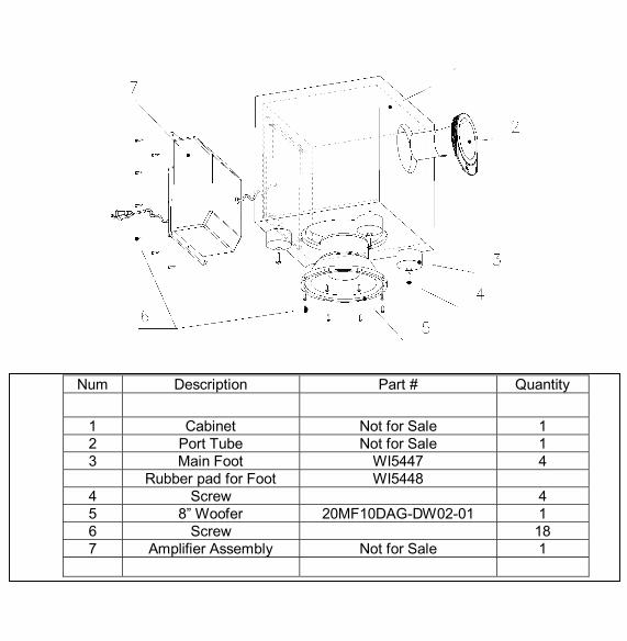
Num Description Part # Quantity
1 Cabinet Not for Sale 12 Port Tube Not for Sale 13 Main Foot WI5447 4
Rubber pad for Foot WI54484 Screw 45 8” Woofer 20MF10DAG-DW02-01 16 Screw 187 Amplifier Assembly Not for Sale 1
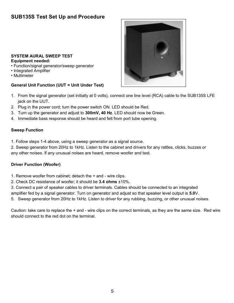
SUB135S Test Set Up and Procedure
SYSTEM AURAL SWEEP TESTEquipment needed:• Function/signal generator/sweep generator• Integrated Amplifier• Multimeter
General Unit Function (UUT = Unit Under Test)
1. From the signal generator (set initially at 0 volts), connect one line level (RCA) cable to the SUB135S LFEjack on the UUT.
2. Plug in the power cord; turn the power switch ON. LED should be Red.3. Turn up the generator and adjust to 300mV, 40 Hz. LED should now be Green.4. Immediate bass response should be heard and felt from port tube opening.
Sweep Function
1. Follow steps 1-4 above, using a sweep generator as a signal source.2. Sweep generator from 20Hz to 1kHz. Listen to the cabinet and drivers for any rattles, clicks, buzzes orany other noises. If any unusual noises are heard, remove woofer and test.
Driver Function (Woofer)
1. Remove woofer from cabinet; detach the + and - wire clips.2. Check DC resistance of woofer; it should be 3.4 ohms ±10%.3. Connect a pair of speaker cables to driver terminals. Cables should be connected to an integratedamplifier fed by a signal generator. Turn on generator and adjust so that speaker level output is 5.0V.5. Sweep generator from 20Hz to 1kHz. Listen to driver for any rubbing, buzzing, or other unusual noises.
Caution: take care to replace the + and - wire clips on the correct terminals, as they are the same size. Red wireshould connect to the red dot on the terminal.
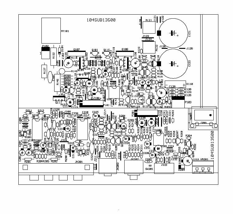
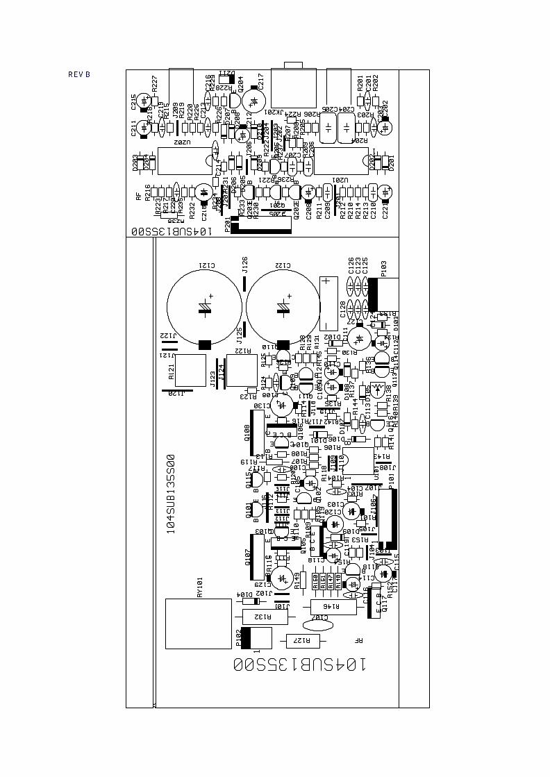
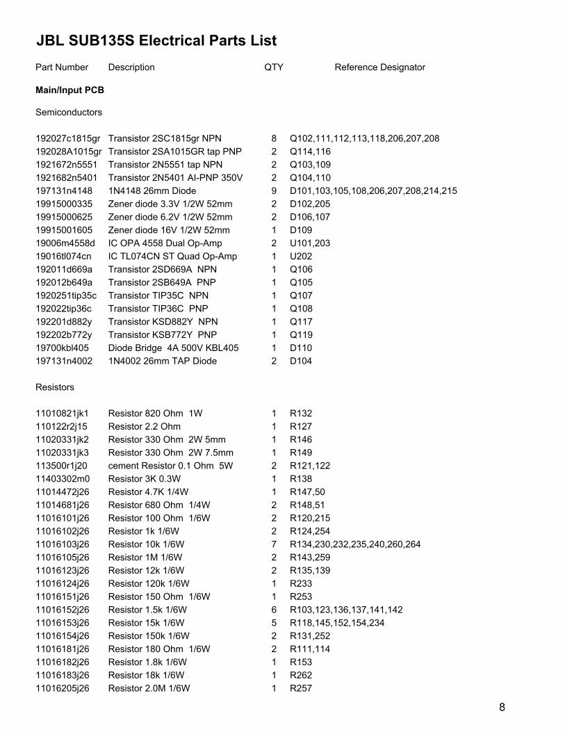
JBL SUB135S Electrical Parts List
Part Number Description QTY Reference Designator
Main/Input PCB
Semiconductors
192027c1815gr Transistor 2SC1815gr NPN 8 Q102,111,112,113,118,206,207,208
192028A1015gr Transistor 2SA1015GR tap PNP 2 Q114,116
1921672n5551 Transistor 2N5551 tap NPN 2 Q103,109
1921682n5401 Transistor 2N5401 AI-PNP 350V 2 Q104,110
197131n4148 1N4148 26mm Diode 9 D101,103,105,108,206,207,208,214,215
19915000335 Zener diode 3.3V 1/2W 52mm 2 D102,205
19915000625 Zener diode 6.2V 1/2W 52mm 2 D106,107
19915001605 Zener diode 16V 1/2W 52mm 1 D109
19006m4558d IC OPA 4558 Dual Op-Amp 2 U101,203
19016tl074cn IC TL074CN ST Quad Op-Amp 1 U202
192011d669a Transistor 2SD669A NPN 1 Q106
192012b649a Transistor 2SB649A PNP 1 Q105
1920251tip35c Transistor TIP35C NPN 1 Q107
192022tip36c Transistor TIP36C PNP 1 Q108
192201d882y Transistor KSD882Y NPN 1 Q117
192202b772y Transistor KSB772Y PNP 1 Q119
19700kbl405 Diode Bridge 4A 500V KBL405 1 D110
197131n4002 1N4002 26mm TAP Diode 2 D104
Resistors
11010821jk1 Resistor 820 Ohm 1W 1 R132
110122r2j15 Resistor 2.2 Ohm 1 R127
11020331jk2 Resistor 330 Ohm 2W 5mm 1 R146
11020331jk3 Resistor 330 Ohm 2W 7.5mm 1 R149
113500r1j20 cement Resistor 0.1 Ohm 5W 2 R121,122
11403302m0 Resistor 3K 0.3W 1 R138
11014472j26 Resistor 4.7K 1/4W 1 R147,50
11014681j26 Resistor 680 Ohm 1/4W 2 R148,51
11016101j26 Resistor 100 Ohm 1/6W 2 R120,215
11016102j26 Resistor 1k 1/6W 2 R124,254
11016103j26 Resistor 10k 1/6W 7 R134,230,232,235,240,260,264
11016105j26 Resistor 1M 1/6W 2 R143,259
11016123j26 Resistor 12k 1/6W 2 R135,139
11016124j26 Resistor 120k 1/6W 1 R233
11016151j26 Resistor 150 Ohm 1/6W 1 R253
11016152j26 Resistor 1.5k 1/6W 6 R103,123,136,137,141,142
11016153j26 Resistor 15k 1/6W 5 R118,145,152,154,234
11016154j26 Resistor 150k 1/6W 2 R131,252
11016181j26 Resistor 180 Ohm 1/6W 2 R111,114
11016182j26 Resistor 1.8k 1/6W 1 R153
11016183j26 Resistor 18k 1/6W 1 R262
11016205j26 Resistor 2.0M 1/6W 1 R257
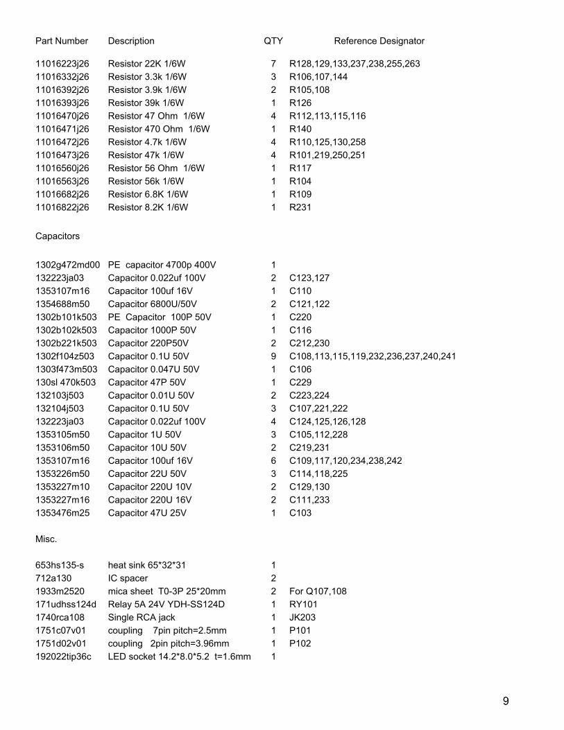
Part Number Description QTY Reference Designator
11016223j26 Resistor 22K 1/6W 7 R128,129,133,237,238,255,263
11016332j26 Resistor 3.3k 1/6W 3 R106,107,144
11016392j26 Resistor 3.9k 1/6W 2 R105,108
11016393j26 Resistor 39k 1/6W 1 R126
11016470j26 Resistor 47 Ohm 1/6W 4 R112,113,115,116
11016471j26 Resistor 470 Ohm 1/6W 1 R140
11016472j26 Resistor 4.7k 1/6W 4 R110,125,130,258
11016473j26 Resistor 47k 1/6W 4 R101,219,250,251
11016560j26 Resistor 56 Ohm 1/6W 1 R117
11016563j26 Resistor 56k 1/6W 1 R104
11016682j26 Resistor 6.8K 1/6W 1 R109
11016822j26 Resistor 8.2K 1/6W 1 R231
Capacitors
1302g472md00 PE capacitor 4700p 400V 1
132223ja03 Capacitor 0.022uf 100V 2 C123,127
1353107m16 Capacitor 100uf 16V 1 C110
1354688m50 Capacitor 6800U/50V 2 C121,122
1302b101k503 PE Capacitor 100P 50V 1 C220
1302b102k503 Capacitor 1000P 50V 1 C116
1302b221k503 Capacitor 220P50V 2 C212,230
1302f104z503 Capacitor 0.1U 50V 9 C108,113,115,119,232,236,237,240,241
1303f473m503 Capacitor 0.047U 50V 1 C106
130sl 470k503 Capacitor 47P 50V 1 C229
132103j503 Capacitor 0.01U 50V 2 C223,224
132104j503 Capacitor 0.1U 50V 3 C107,221,222
132223ja03 Capacitor 0.022uf 100V 4 C124,125,126,128
1353105m50 Capacitor 1U 50V 3 C105,112,228
1353106m50 Capacitor 10U 50V 2 C219,231
1353107m16 Capacitor 100uf 16V 6 C109,117,120,234,238,242
1353226m50 Capacitor 22U 50V 3 C114,118,225
1353227m10 Capacitor 220U 10V 2 C129,130
1353227m16 Capacitor 220U 16V 2 C111,233
1353476m25 Capacitor 47U 25V 1 C103
Misc.
653hs135-s heat sink 65*32*31 1
712a130 IC spacer 2
1933m2520 mica sheet T0-3P 25*20mm 2 For Q107,108
171udhss124d Relay 5A 24V YDH-SS124D 1 RY101
1740rca108 Single RCA jack 1 JK203
1751c07v01 coupling 7pin pitch=2.5mm 1 P101
1751d02v01 coupling 2pin pitch=3.96mm 1 P102
192022tip36c LED socket 14.2*8.0*5.2 t=1.6mm 1
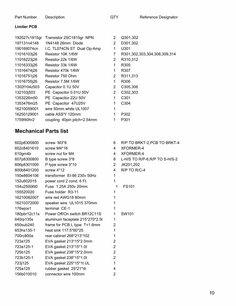
Part Number Description QTY Reference Designator
Limiter PCB
192027c1815gr Transistor 2SC1815gr NPN 2 Q301,302
197131n4148 1N4148 26mm Diode 2 D301,302
19016tl074cn I.C. TL074CN ST Dual Op-Amp 1 U301
11016103j26 Resistor 10K 1/6W 7 R301,302,303,304,308,309,314
11016223j26 Resistor 22k 1/6W 2 R310,312
11016333j26 Resistor 33k 1/6W 1 R305
11016474j26 Resistor 470k 1/6W 1 R307
11016751j26 Resistor 750 Ohm 2 R311,313
11016755j26 Resistor 7.5M 1/6W 1 R306
1302f104z503 Capacitor 0.1U 50V 2 C305,306
132103j503 PE Capacitor 0.01U 50V 2 C302,303
1353226m50 PE Capacitor 22U 50V 1 C301
1353476m25 PE Capacitor 47U25V 1 C304
16210059001 wire 50mm white UL1007 1
16250129001 cable ASS'Y 120mm 1 P302
1759f40hr2 coupling 40pin pitch=2.54mm 1 P301
Mechanical Parts list
602p8300800 screw M3*8 6 R/P TO BRKT-2,PCB TO BRKT-4
602c8401610 screw M4*16 4 XFORMER-4
610gm4b screw nut for M4 4 XFORMER-4
607p8300800 B type screw 3*8 8 L-H/S TO R/P-6,R/P TO S-H/S-2
606p8301000 P type screw 3*10 2 JK201,202
600b8401200 screw 4*12 4 R/P TO R/C-4
150e8604106 transformer EI-86 230v 50Hz 1
152u602015 power cord 2 cond. 6 Ft. 1
154u25006t0 Fuse 1.25A 250v 20mm 1 FS101
155520020 Fuse holder R3-11 1
16210082007 wire red AWG18 80mm 1
16210372000 speaker wire UL1015 370mm 1
176wjce1 terminal CE-1 1
180pbr12c11s Power Off/On switch BR12C11S 1 SW101
640rp135s aluminum faceplate 215*270*2.5t 1
650sub240 frame for PCB L type T=1.6mm 2
653hs135-1 heat sink 117.5*60*25 1
700rc800a rear cabinet 268*213*102 1
723a125 EVA gasket 213*15*2.0mm 2
723a125-1 EVA gasket 213*15*1.0t 2
725b125 EVA gasket 238*15*2.0mm 2
723b125-1 EVA gasket 238*15*1.0t 2
723j125 EVA gasket 225*15*1t UL 1
725a125 rubber gasket 25*21*4t 4
156b010010 connector wire 100mm 2