Embed Size (px)
Citation preview

Cinema Processor System
QUICK START GUIDE1st Edition (Revised 1)
DIGITAL FILM SOUND READER
DFP-R3000
DIGITAL FILM SOUND DECODER
DFP-D3000
®


1DFP-3000
Table of Contents
Check List ........................................................................................................... 3
1. Introduction ............................................................................................ 1-1
2. Equipment and accessories ............................................... 2-1
3. Basic checks of site and installation ...................................... 3-1
4. Checks of correct DFP-R3000 Reader mounting ............ 4-1
5. A-Chain alignment using DFP-D3000 front panelcontrols ..................................................................................................... 5-1
6. B-Chain Alignment ............................................................................. 6-1
7. Overall systems check and listening test ............................ 7-1
8. Troubleshooting .................................................................................. 8-1
9. Appendix .................................................................................................. 9-1
9.1 DFP-D3000 Rear Panel Connector Pin Assignment ................................... 9-1
9.2 DFP-D3000 Input/Output Level ................................................................. 9-4
9.3 Changeover Settings .................................................................................... 9-5
9.4 Settings for using DFP-D3000 as DFP-D2000 ........................................... 9-69.4.1 Conditions .................................................................................. 9-69.4.2 Connections and Settings When Connecting to the Output
of the Existing System ............................................................... 9-69.4.3 Connections and Settings When Connecting to the Input
of the Existing System ............................................................... 9-9
9.5 Description on Connection of DA-20 and DFP-D3000 ............................ 9-129.5.1 Outline of System ..................................................................... 9-129.5.2 Requirements at SDDS Side .................................................... 9-129.5.3 Connections of the DA-20 and Setting the Operation Mode ... 9-129.5.4 Connections for Using AUX1 Input ........................................ 9-139.5.5 Connections for Using AUX2 Input ........................................ 9-159.5.6 Audio Connecting the DA-20 and DFP-D3000 ....................... 9-17
9.6 Connecting the CP-500 and DFP-3000 ..................................................... 9-189.6.1 Connecting the DFP-D3000 to the CP-500 with
the DFP-D3000 as master ........................................................ 9-189.6.2 Connecting the DFP-3000 to the CP-500 with
the CP-500 as master ................................................................ 9-23

2 DFP-3000
9.7 Connecting the DTS-6, DTS-6D and DFP-D3000 ................................... 9-269.7.1 Outline of System ..................................................................... 9-269.7.2 Requirements of SDDS Side .................................................... 9-269.7.3 Connecting the DTS Processor DTS-6 .................................... 9-269.7.4 Connection of Control Signals from DTS Processor DTS-6D .... 9-319.7.5 Audio Connecting the DTS-6, DTS-6D and DFP-D3000 ....... 9-36
9.8 Corresponding to DFP-D3000 Surround EX ............................................ 9-379.8.1 Restrictions on Control of Surround EX Decoder ................... 9-379.8.2 Connections of Audio System .................................................. 9-379.8.3 Actual Connection of Control System ..................................... 9-399.8.4 SA-10 Operations When Controlling from the DFP-D3000 .... 9-409.8.5 Controlling Surround EX from DA-20 .................................... 9-419.8.6 Controlling Surround EX from DTS-6 or DTS-6D ................. 9-439.8.7 Controlling Surround EX control
from Automation Controller .................................................... 9-439.8.8 Adjustments of Audio System ................................................. 9-44
9.9 Test Cable for Performing A-Chain Adjustment ...................................... 9-51
9.10 Adjusting the Analog Track Pickup .......................................................... 9-529.10.1 Preliminary Preparations Before Adjustments ......................... 9-529.10.2 Lateral Film Guide Adjustment ............................................... 9-529.10.3 Lateral Exciter Lamp Adjustment ............................................ 9-529.10.4 Lateral Solar Cell Adjustment .................................................. 9-529.10.5 Vertical Adjustment of Exciter Lamp ...................................... 9-539.10.6 Slit Lens Adjustment ................................................................ 9-539.10.7 Double Checking of Illumination Inconsistency ...................... 9-539.10.8 Wiring Check ........................................................................... 9-53
9.11 Description of the DFP-D3000 Setup Software Menus ............................ 9-549.11.1 Start-up Screen ......................................................................... 9-549.11.2 Description of File Menu Items ............................................... 9-569.11.3 Description of Config Menu Items .......................................... 9-579.11.4 Description of Preset Menu Items ............................................ 9-589.11.5 Description of A-Chain Menu Items ........................................ 9-599.11.6 Description of Tools Menu Items ............................................ 9-609.11.7 Description of Master Menu Items .......................................... 9-619.11.8 Description of Test Menu Items ............................................... 9-629.11.9 Description of Help Menu Items .............................................. 9-63
nSDDS is a registered trademark of Sony Corporation.DTS, DTS ES and DTS Extended Surround are trademarks or registered trademarksof Digital Theater Systems, Inc.Dolby, Dolby Digital and Dolby Surround are trademarks or registered trademarksof Dolby Laboratories Licensing Corporation.
Unless otherwise specified, all name of companies and products are trademarks orregistered trademarks of the respective companies.

3DFP-3000
Check list
This is a step by step check list for the experienced installer. Refer to the associated sectionsof this Guide for additional information and see the Tech Notes for specific details.
Page
1. Read about the advanced features of the DFP-3000 Player System. .......... 1-1
2. Check that you have all necessary components and equipment. ................ 2-12.1 Components included with the DFP-D3000 Decoder. .................... 2-12.2 Components included with the DFP-R3000 Reader. ....................... 2-12.3 Additional equipment available from Sony. .................................... 2-12.4 Personal equipment you will need. .................................................. 2-1
3. Perform basic checks of the Decoder. ......................................................... 3-13.1 Ensure that the Decoder’s installed environment is acceptable. ...... 3-13.2 Connect the Reader to the Decoder, turn on mains power,
and confirm activity. ........................................................................ 3-1Caution! Do not hot-plug the Reader!
3.3 Confirm that the Decoder firmware is version 2.74 or later. ........... 3-13.4 Confirm that the Setup Software on your laptop is version
2.00 build 2.055 or later. Check Tech Note TN99121401for the latest version. ........................................................................ 3-2
3.5 Confirm a solid earth ground for the Decoder chassis. .................... 3-23.6 Be sure that the optical input connector is wired correctly-
it’s not the same as others’. .............................................................. 3-23.7 Confirm that the interface wiring has been done properly.
The Appendices and Tech Notes offer details on specificinstallation issues. ............................................................................... 3-2
4. Confirm that the Reader is mounted correctly on the projector. ................. 4-14.1 Confirm the correct installation for your projector according
to the DFP-R3000 Installation Guide that comes with the Reader. ..... 4-14.2 Be sure you have at least 32 frames between the Reader LEDs
and the gate. ....................................................................................... 4-14.3 Make sure the film path is not twisted or misaligned. ..................... 4-1
5. Align the A-Chain. ...................................................................................... 5-15.1 Align and clean the solar cell and optics. See Tech Note
99111901 for details. ............................................................................5-15.2 Connect your test cable, X-Y oscilloscope, and real time
analyzer (RTA) to the front panel Headphone jack(see Tech Note TN99101201 for instructions on making this cable).Use Monitor Select position 1.Use the Decoder’s front panel facilities to perform A-Chain calibration. .. 5-1
5.3 Go to the Config menu and enter the default password “SONY”. ...... 5-15.4 Play a tone loop and trim the gain for projector 1 (OPT1)
L and R inputs.Block the slit slowly and confirm that R drops before L. .................5-3

4 DFP-3000
Page5.5 Play a B&W pink noise loop and set the slit loss EQ frequency
for L and R.Repeat 5.4, 5.5, and 5.6 for the second projector of achangeover installation. ....................................................................... 5-4
6. Align the B-Chain. ...................................................................................... 6-16.1 Connect your laptop to the Decoder’s RS232 port with
a null-modem serial cable, launch the Setup Software,and “connect” the Software to the Decoder. .................................... 6-1
6.2 Open the Master DFP-3000 screen and set the MasterVolume to 0.0 dB and set the -20 dBFS output levelreference to -10 dBu. ....................................................................... 6-1
6.3 Zero out the Software on the main screen, link Mutes toSelects, and bring up the Test Signal screen. ................................... 6-1
6.4 Select pink noise; select All On; use PC function keysto select output channels. ................................................................. 6-2
6.5 Check that noise is coming from the selected non-subchannel at about 85 dB SPL, or 82 dB for the L and Rsurround speakers. ........................................................................... 6-3
6.6 Use your RTA and each non-sub channel’s graphic EQto dial in the X-curve for each speaker except the subwoofer. ........ 6-3
6.7 Adjust each screen speaker to exactly 85 dB SPL and thesurrounds to 82 dB SPL. .................................................................. 6-3
6.8 Set the subwoofer channel’s parametric EQ forsmooth response ; set each preset’s subwoofer low pass filterto 100 Hz or lower except SDDS, which should be higher. ............ 6-4
6.9 Referring to your RTA, set the level of the analog subwooferso that its bands are about the same level as the centerspeaker’s bands in its flat response region. ...................................... 6-4
6.10 Again referring to your RTA, set the level of the digital (SDDS)subwoofer bands to 10 dB higher than the flat bands of the centerspeaker. ............................................................................................ 6-5
6.11 Set the surround channel delay for each appropriate Preset. ........... 6-66.12 Set AUX inputs’ subwoofer levels to +10 dB, if other digital
systems are installed. ....................................................................... 6-6
Page6.13 Adjust the sync between optical tracks and SDDS. ......................... 6-76.14 Configure your presets for names, output matrix, and fallback. ...... 6-76.15 Match levels between presets using the trims; set bypass levels;
set HI levels. .................................................................................. 6-10
7. Perform an overall systems checkout and listening test. ............................ 7-1
8. Refer to the Troubleshooting section for help with problemsyou encounter. ............................................................................................. 8-1
9. Appendix with connector pinout charts. .................................................... 9-1
1-1DFP-3000
1. Introduction
The Sony DFP-3000 Cinema Processor forms the heart of the projection booth sound system in yourtheatre. It provide a sophisticated system for playing SDDS digital sound tracks, high quality opticalsoundtrack playback, comprehensive B-Chain control, and many other features. Here are just a few:
. The DFP-3000 system of projector-mounted reader and rack-mounted decoder perform traditionalaudio processing entirely in the digital domain. Inputs are processed with 20-bit A/D converters andthen slit-loss EQ, noise reduction, and matrix decoding are all processed and adjusted digitally. After B-chain processing, fully balanced outputs are driven by 20-bit D/A converters.
. A comprehensive fallback system with two auxiliary inputs permits automatic playback of all threedigital sound systems (by connecting the analog outputs of the other digital decoders into the AUXinputs of the DFP-D3000) as well as optical and non-sync inputs. You can select an AUX input to playin the event there is no SDDS digital soundtrack, a second auxiliary input to play if the first has novalid audio, and optical to play automatically if no digital soundtrack of any kind is available.
. The B-Chain system of the DFP-3000 is exceptionally flexible. It provides seven channels of multi-band graphic equalization, surround delays, subwoofer parametric EQ and separate low pass filter foroptical and digital play, and many other functions. These are all implemented in powerful DSP’s tomake setup fast and easy using Windows-based software.
. SDDS Fader Automation lets you set levels reel by reel. Your settings are retained in non-volatilememory and automatically restored whenever that reel is played again.
. A front panel headphone monitor with selection switch lets you perform many tests using headphonesor test equipment directly at the decoder front panel.
. The DFP-3000 is designed for professional applications as well as cinemas. It has balanced inputs andoutputs for lowest noise and you can select professional operating references if required.
This Quick Start Guide is intended to assist experienced cinema engineers in systematically installing,setting up, and maintaining the Sony DFP-3000 cinema processor system. Instructions are complete, butbrief. For more detailed information, Sony offers the following comprehensive manuals:
DFP-R3000 Installation Manual (for installation of the Reader)DFP-R3000 Maintenance Manual (for component-level service of the Reader)DFP-D3000 Maintenance Manual (for component-level service of the Decoder)
The information in this Guide is presented in the same order that most cinema engineers follow whensetting up a new theatre. If you go through the sections step-by-step you will be sure to touch on the mostimportant points.
Sony Cinema Products would like to hear from you. We hope you will contact us and tell us your experi-ences in using this Guide so that we may constantly improve its value to you.

2-1DFP-3000
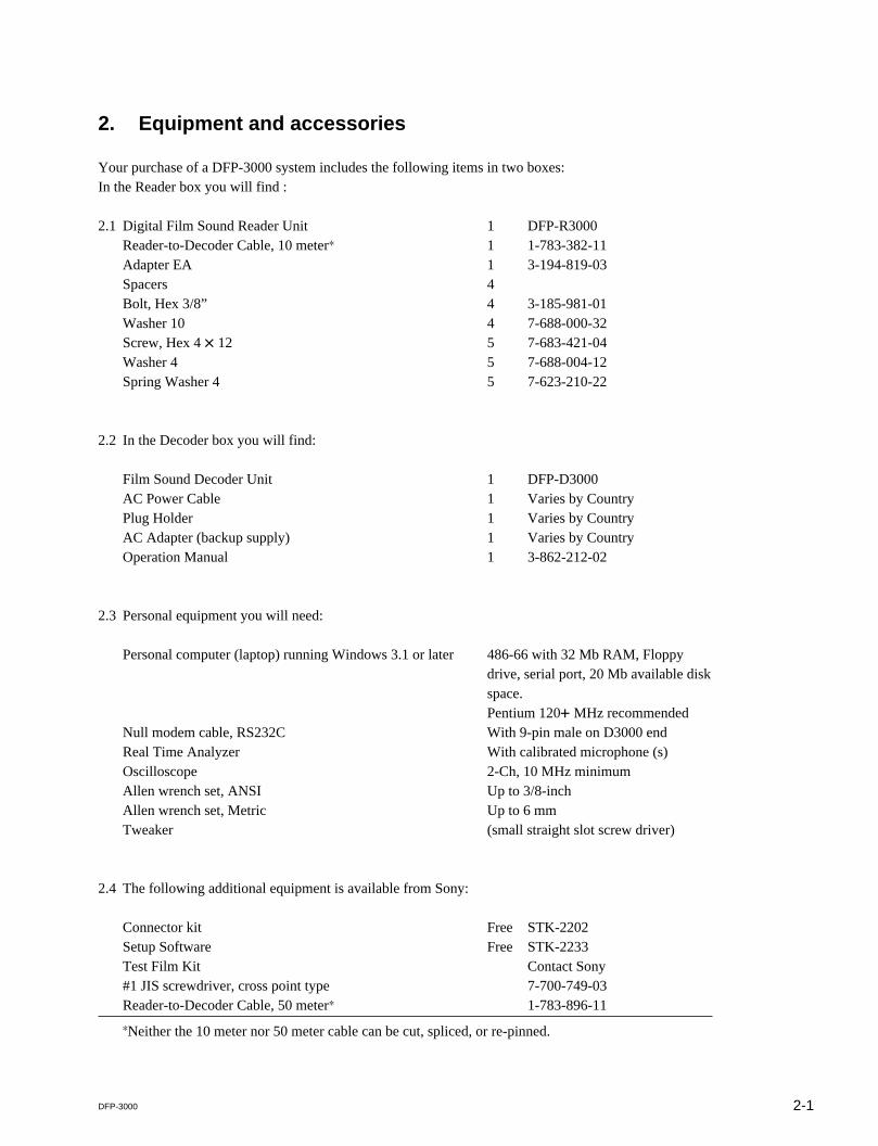
2. Equipment and accessories
Your purchase of a DFP-3000 system includes the following items in two boxes:In the Reader box you will find :
2.1 Digital Film Sound Reader Unit 1 DFP-R3000Reader-to-Decoder Cable, 10 meter* 1 1-783-382-11Adapter EA 1 3-194-819-03Spacers 4Bolt, Hex 3/8” 4 3-185-981-01Washer 10 4 7-688-000-32Screw, Hex 4 x 12 5 7-683-421-04Washer 4 5 7-688-004-12Spring Washer 4 5 7-623-210-22
2.2 In the Decoder box you will find:
Film Sound Decoder Unit 1 DFP-D3000AC Power Cable 1 Varies by CountryPlug Holder 1 Varies by CountryAC Adapter (backup supply) 1 Varies by CountryOperation Manual 1 3-862-212-02
2.3 Personal equipment you will need:
Personal computer (laptop) running Windows 3.1 or later 486-66 with 32 Mb RAM, Floppydrive, serial port, 20 Mb available diskspace.Pentium 120+ MHz recommended
Null modem cable, RS232C With 9-pin male on D3000 endReal Time Analyzer With calibrated microphone (s)Oscilloscope 2-Ch, 10 MHz minimumAllen wrench set, ANSI Up to 3/8-inchAllen wrench set, Metric Up to 6 mmTweaker (small straight slot screw driver)
2.4 The following additional equipment is available from Sony:
Connector kit Free STK-2202Setup Software Free STK-2233Test Film Kit Contact Sony#1 JIS screwdriver, cross point type 7-700-749-03Reader-to-Decoder Cable, 50 meter* 1-783-896-11
*Neither the 10 meter nor 50 meter cable can be cut, spliced, or re-pinned.

3-1DFP-3000
3. Basic checks of site and installation.
Before you begin making settings and adjustments to your DFP-3000 system, it’s best to confirm some basic conditions.Here is a check list.
3.1 Check that the Decoder environment is suitable.The DFP-D3000 Decoder is intended to be mounted in a rack chassis along with other cinema equipment. However, itshould not be mounted in close proximity to power amplifiers or other equipment which may radiate strong magnetic fieldsor which give off high heat. Observe the ambient temperature limit of 40° C (104° F) and if the interior of the rack isexcessively warm, provide more ventilation to lower the temperature.nDo not “hot plug” the Reader! The Reader gets its power through the cable that connects it to the Decoder. Do notremove or install this cable while the Decoder AC power is on. Doing so may cause damage to the Reader and void itswarranty.
3.2 Confirm basic power up activity.Connect the Reader to the Decoder using its cable. Note that this special cable cannot be cut or spliced. Connect the linecord to a mains supply of 100-240 VAC 50/60 Hz and connect the backup power supply to a mains supply for which it israted. The LED in the SELECT switch will be illuminated Red. Switch on the Decoder. The SELECT switch LED will goout, the LCD display will be illuminated, the MASTER LEVEL numerical display will go through a brief count and thendisplay its last +/_ dB setting. The illuminated PRESET switch shows the last and current Preset selected and the LCDdisplay shows its name and any fallback Preset that is assigned to it.
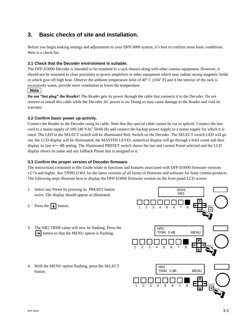
3.3 Confirm the proper version of Decoder firmware.The instructions contained in this Guide relate to functions and features associated with DFP-D3000 firmware versionsv2.74 and higher. See TN99121401 for the latest versions of all forms of firmware and software for Sony cinema products.The following steps illustrate how to display the DFP-D3000 firmware version on the front panel LCD screen:
SELECT1 2 3 4 5 6 7 8
SDDSNR2
SELECT1 2 3 4 5 6 7 8
NR2TRIM: 0 dB MENU
1. Select any Preset by pressing its PRESET buttontwice. The display should appear as illustrated.
2. Press the button.
3. The NR2 TRIM value will now be flashing. Press the button so that the MENU option is flashing.
4. With the MENU option flashing, press the SELECTbutton.
SELECT1 2 3 4 5 6 7 8
NR2TRIM: 0 dB MENU

3-2 DFP-3000
5. The STATUS option will now be flashing. Press theSELECT button again.
6. The firmware version will now be indicated in theupper right corner of the LCD display.
7. Press the SELECT button while the EXIT option isflashing to leave this area of the menu system.
SELECT1 2 3 4 5 6 7 8
STATUS CONFIG TEST
SELECT1 2 3 4 5 6 7 8
PWR ON: 0 0 0 0 0 v2.74FILMRUN: 0 0 0 0 0 EXIT
3.4 Check the version of the Setup Software on your computer.The Setup Software is updated frequently. Be sure you are using the latest version, which will be v2.00,build 2.055 or higher. You can check the SDDS web site or contact Sony Cinema Products to determinethe latest version and to request a free copy. You can check the version of Setup Software you are usingby launching the program and selecting Help>About. . . from the pull down menu at the top of the mainscreen.
3.5 Confirm a proper chassis earth ground.Most audio grounding schemes require that the chassis of the DFP-D3000 have a solid electrical connec-tion to the rack in which it is mounted. The finish on the rack mounting rails may be very durable. Makesure that the mounting screws cut through the finish of the DFP-D3000 and that the mounting ears makeelectrical connection through the rack rails’ finish to the rack itself. Test this with an ohm meter. Addi-tionally, a screw terminal Technical Ground is available on the back panel of the Decoder, to help make asolid ground connection. Do not remove the line cord safety ground pin in an attempt to avoid groundloops. This precaution is already taken care of in the design of the DFP-D3000 and removing the pin willhave no benefit, but doing so will compromise electrical safety and may violate electrical codes.
3.6 Check the optical input connector wiring.Make sure that the optical input connector is wired according to the pinout diagram in the Appendix. Useindividually shielded twisted pair cable. See Chapter 5, A-Chain Alignment, for information regarding theoptical pre-amp test points. Note that the wiring of this connector may not correspond to that of othercinema processors.
3.7 Confirm proper audio interface wiring.The Sony DFP-D3000 Decoder unit uses professionally balanced audio interface connectors, pinnedaccording to the THX convention, for interconnections to amplifiers, crossovers, limiters, booth monitors,and other cinema processors. Unfortunately, many such devices do not employ balanced inputs oroutputs. It is essential that proper balanced to unbalanced interface wiring techniques are used whenconnecting to these devices so as to ensure optimum operating conditions for the DFP-D3000 and con-nected equipment. Failure to use proper techniques in your sound rack wiring may result in reducedsystem headroom, improper theatre calibration, and compromised sound performance. For a guide toproperly interconnecting balanced and unbalanced audio signals, refer to Tech Note TN99060401.

3-3DFP-3000
Wiring of other equipment.This following is an illustration of the DFP-D3000 rear panel.
Note that these D-Sub connectors have metric (M2.5 x .45) jack screw receptacles and require matingconnectors with metric jack screws. A kit of such connectors is provided with each DFP D3000. Do notuse standard D-Sub connectors with 4-40 jack screws.
Cinema processors.Refer to the list of available Tech Notes in the Appendix of this Guide for instructions on correct audioand logic interconnections to other cinema processors. Note that Sony connectors use the THX® pinoutconvention, but other equipment may not. Therefore, pre-fabricated cables or cables made with flat ribboncomputer-type cable are generally not acceptable for use with the DFP-D3000. The DFP-3000 cinemaprocessor is capable of exceptional performance; do not degrade this by using inferior cables. Sonystrongly recommends that all audio interconnections in your cinema sound rack be made using highquality audio-grade twisted pair shielded cables or individually shielded multipair cable. Contact yourdealer for information regarding pre-wired audio cables for the DFP-D3000, available from severalcinema accessory distributors.
Non-sync inputs.The non-sync inputs of the DFP-D3000 are on consumer standard RCA-type connectors. One dedicatednon-sync input is available. If additional non-sync inputs are required, the MIC1 input can easily beconfigured for line level operation, and the two eight-channel AUX inputs can serve as additional linelevel inputs for electronic projectors, DVD, magnetic film dubbers, and other external analog soundsources.
Microphone inputs.The MIC1 and MIC2 inputs have built in microphone preamplifiers, so that external mixers or line-matching devices are not required to directly connect a microphone level input. Input connections arebalanced on a single D-Sub 9-pin female connector. 48-volt phantom power for condenser microphones isavailable, and can be switched on using the setup software or the front panel. See the instructions for MICconfiguration later in this Guide for more detailed information.
OUTPUT INPUT PROJECTOR I/0
CONTROL I/0
MONITOR OUTPUT MIC INPUT NON-SYNCR L
1 READER 2
SYSTEM OUTPUT REMOTELEVEL
CONTROLAUX INPUT 1 1 OPTICAL 2
AUX INPUT 2PHONES AUTOMATIONRS-232C RS-422
15V
To balanced inputsof booth monitor
From Mic 1and Mic 2
From Non-syncplayer
From Projector 1optical reader
To power ampsand loudspeakers
To phonesand HI
From othercinema processors
Automation logicinputs and outputs
To laptop PC via null modem cable
Backupsupply
Chassisground
From Projector 1R3000 Reader
120 / 230VAC
3-4 DFP-3000
AUX inputs.If either of the two 8-wide balanced AUX inputs are used for sources other than cinema processors, takenote that the sophisticated automatic fallback system of the DFP-3000 requires these inputs to be enabledby a logic command to make them active. To use AUX1 or AUX2 for external sound sources other thandigital film sound decoders, short Pin 34 (AUX1 DATA OK) or Pin 35 (AUX2 DATA OK) to GROUNDon the Automation connector to enable the AUX1 or AUX2 inputs. See Tech Note TN99042801. Anotherapproach is to chose No Fallback (*) as the fallback option for an AUX Preset, which prevents fallbackand so forces the AUX input to play whenever it is selected.
Headphones and HI output.A single D-Sub 9 pin connector provides a L/R stereo headphone output from the back panel. This is aparallel of the front panel headphone jack and is affected by the MONITOR SELECT switch and HEAD-PHONES level control. This connector also has two pins providing MONO outputs, which can be used tofeed most Hearing Impaired transmission systems. Signal level for the HI outputs can be calibrated by anadjustment control located inside the Decoder. Detailed instructions for Hearing Impaired output leveladjustment is discussed in Section 6.15 of this Guide.
Automation inputs and outputs.All automation logic inputs and outputs are brought to a single 37-pin D-Sub connector on the DFP-D3000. For a complete description of the connections available, see Tech Note TN99042801. Other TechNotes describe specific means of connecting to other types of cinema equipment; see Tech NoteTN99070701.
RS-232C connector.This 9-pin female D-Sub connector is used to connect an external PC-compatible computer using a null-modem cable.
RS-422 connector.Contact your Sony service or sales representative for details on the use of this connector.
Remote level control.Remote control of the Master Volume is possible by connecting a 100k-ohm linear taper potentiometer.The wiring convention of this potentiometer is unique to Sony, so follow the documentation in theAppendix carefully.
Bypass (backup) power supply.The DFP-D3000 is provided with an external DC power supply which provides emergency power tobypass components within the Decoder. This power supply allows the Decoder to continue playingoptical tracks in the event its main power has been turned off. Check that this power supply has thecorrect AC mains voltage rating for your country and is connected to the AC mains and to the back of theDecoder. A small red LED in the SELECT switch on the front panel of the Decoder indicates when theunit is being powered only by the backup power supply.
4-1DFP-3000
4. Checks of correct DFP-R3000 Reader mounting.
Do not “hot plug” the Reader!The Reader gets its power through the cable that connects it to the Decoder. Do not remove or install thiscable while the Decoder power is on. Doing so may cause damage to the Reader and void the warranty.
4.1 Confirm the minimum frame offset.Specific installation instructions for mounting the Reader to each type of projector are available in theDFP-R3000 Installation Guide provided with the Reader. Following these instructions will ensure at leastthe minimum frame offset between the Reader’s LEDs and the picture gate. The Reader LED offset mustbe at least 32 frames ahead of the projector gate. Since the loop ahead of the intermittent affects thisoffset, use a nominal loop when making this determination. The maximum total frame offset possiblewith the DFP-3000 is 115 frames.
4.2 Check the film path alignment.Proper alignment of the film path entering and exiting the Reader, as well as adequate tension on theincoming film, is essential to correct operation of the DFP-R3000 Reader. Carefully check that the allrollers on the in-feed mechanism, the Reader, the Adapter plate, and the projector are aligned and that notwisting of the film path occurs. Adjust the positioning of the Reader if necessary.


5-1DFP-3000
5. A-Chain alignment using DFP-D3000 front panel controls
The most direct means of A-Chain alignment is to use with external test equipment and the controlsavailable through the Decoder front panel. There are two approaches. The first, recommended for experi-enced cinema engineers, is to align the projector’s optical playback system so as to produce nominalsettings (preset gain = 0.0 dB) in the DFP-D3000. This has the potential benefit of best sound quality aspreamplifiers, noise reduction, and matrix decoding circuits will be operating at optimal levels. Thesecond approach is to set the DFP-D3000 to match the existing alignments in the projector’s opticalplayback system. This approach has the benefit of ease of setup, but requires that the optical system isalready correctly aligned. Gain trims should end up near 0.0 dB with a properly aligned projector. Witheither approach, it is important to first ensure a high quality optical system alignment. For detailedinstructions on aligning a forward scan optical reader system, see Tech Note TN99111901; to align aspecific brand of reverse scan reader, follow its manufacturer’s documentation.
5.1 The following instructions require that the projector’s optical reader has been properly aligned, theprojector is mechanically sound, and its optical playback system is clean. See TN99111901 for instruc-tions on aligning a forward scan optical reader.
The initial steps for A-Chain alignment are common to both alignment approaches.
5.2.1 Prepare a test cable.This cable connects from a standard 1/4-inch stereo phone plug to the input connectors of your multichan-nel Real Time Analyzer (RTA) and simultaneously to the inputs of your dual-channel X-Y oscilloscope.The front panel phone jack on the Decoder has line-level output signals wired with Tip = Lt, Ring = Rt,and Sleeve = audio common (ground). The Lt and Rt signals connect to each input of your RTA and tothe horizontal and vertical inputs of your oscilloscope. See available Tech Note TN99101201 for detailson making up this test cable.
5.2.2 Connect the test cable.Set up your oscilloscope for X-Y display, i.e., to display phase relationships between two equal signals.Connect the test cable to the X and Y oscilloscope inputs. Connect Lt or Rt to your RTA input. Insert thephone plug end of the test cable into the headphones jack on the front panel of the DFP-D3000.
5.2.3 Set the MONITOR SELECT switch of the Decoder to position 1 (the LCD screen will brieflydisplay L+LC+C+SL/R+RC+SR). Set the adjacent HEADPHONES volume control to the 12:00(straight up) position.
5.3 Enter the A-Chain access password in order to adjust preamplifier gains and set the slit loss equaliza-tion frequency. You will need to play customary alignment films at times during this process. The defaultA-Chain password is “SONY”.

5-2 DFP-3000
SELECT1 2 3 4 5 6 7 8
SDDSNR2
SELECT1 2 3 4 5 6 7 8
NR2TRIM: 0 dB MENU
SELECT1 2 3 4 5 6 7 8
NR2TRIM: 0 dB MENU
SELECT1 2 3 4 5 6 7 8
STATUS CONFIG TEST
SELECT1 2 3 4 5 6 7 8
PASSWORD: S * * *MASTER VOLUME
SELECT1 2 3 4 5 6 7 8
PASSWORD: * * * *MASTER VOLUME
5.3.1 Select any Preset other than non-sync by pressingits PRESET button twice. If you have selectedPreset 8 for SDDS the LCD display will appear asillustrated.
5.3.2 Press the button.
5.3.3 The NR2 TRIM value will now be flashing. Pressthe button so that the MENU option isflashing.
5.3.4 With the MENU option flashing, press the SE-LECT button.
5.3.5 The STATUS option will now be flashing. Pressthe button again. This will cause the CON-FIG option to flash.
5.3.6 With the CONFIG option flashing, press theSELECT button.
5.3.7 Turn the MASTER VOLUME control clockwiseuntil the first character in the password field ischanged to “S”. The default A-Chain password is“SONY”.
5.3.8 When the first character becomes “S”, press theSELECT button to enter it and move to the nextcharacter. Continue using the MASTER VOL-UME control and SELECT button to enter allcharacters of SONY.
5-3DFP-3000
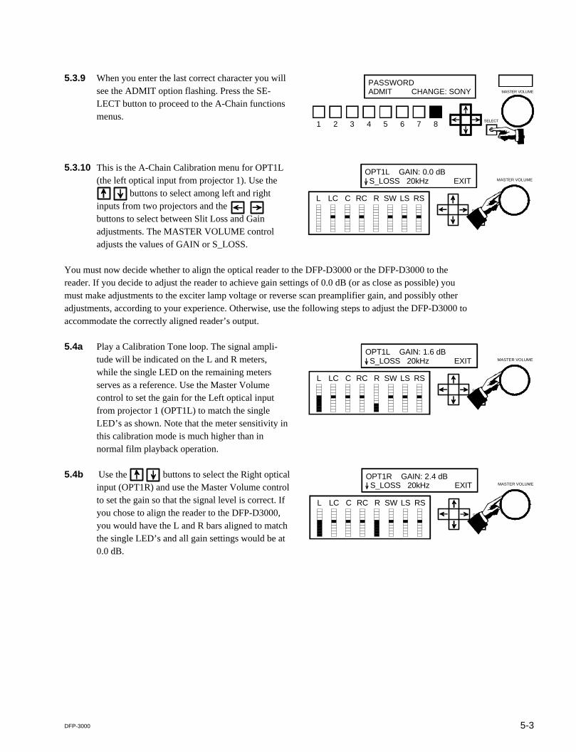
5.3.9 When you enter the last correct character you willsee the ADMIT option flashing. Press the SE-LECT button to proceed to the A-Chain functionsmenus.
5.3.10 This is the A-Chain Calibration menu for OPT1L(the left optical input from projector 1). Use the
buttons to select among left and rightinputs from two projectors and the buttons to select between Slit Loss and Gainadjustments. The MASTER VOLUME controladjusts the values of GAIN or S_LOSS.
You must now decide whether to align the optical reader to the DFP-D3000 or the DFP-D3000 to thereader. If you decide to adjust the reader to achieve gain settings of 0.0 dB (or as close as possible) youmust make adjustments to the exciter lamp voltage or reverse scan preamplifier gain, and possibly otheradjustments, according to your experience. Otherwise, use the following steps to adjust the DFP-D3000 toaccommodate the correctly aligned reader’s output.
SELECT1 2 3 4 5 6 7 8
PASSWORDADMIT CHANGE: SONY MASTER VOLUME
SELECT
OPT1L GAIN: 0.0 dBI S_LOSS 20kHz EXIT MASTER VOLUME
L LC C RC R SW LS RS
SELECT
OPT1L GAIN: 1.6 dBI S_LOSS 20kHz EXIT MASTER VOLUME
L LC C RC R SW LS RS
SELECT
OPT1R GAIN: 2.4 dBI S_LOSS 20kHz EXIT MASTER VOLUME
L LC C RC R SW LS RS
5.4a Play a Calibration Tone loop. The signal ampli-tude will be indicated on the L and R meters,while the single LED on the remaining metersserves as a reference. Use the Master Volumecontrol to set the gain for the Left optical inputfrom projector 1 (OPT1L) to match the singleLED’s as shown. Note that the meter sensitivity inthis calibration mode is much higher than innormal film playback operation.
5.4b Use the buttons to select the Right opticalinput (OPT1R) and use the Master Volume controlto set the gain so that the signal level is correct. Ifyou chose to align the reader to the DFP-D3000,you would have the L and R bars aligned to matchthe single LED’s and all gain settings would be at0.0 dB.

5-4 DFP-3000
SELECT
OPT1L GAIN: 2.4 dBI S_LOSS 16.4kHz EXIT MASTER VOLUME
L LC C RC R SW LS RS
SELECT
OPT1R GAIN: 2.4 dBI S_LOSS 16.4kHz EXIT MASTER VOLUME
L LC C RC R SW LS RS
This completes the A-Chain alignment procedure. To return to the main LCD menu, use the buttons to select the EXIT option and press the SELECT button. You may also press any PRESET buttontwice to exit all menus and return the Decoder to normal operation with that Preset selected and itsparameters loaded.
5.5a Use the buttons to change the selectedparameter to slit loss (S_LOSS). Play a B&W PinkNoise test film and use the Master Volume controlto adjust the slit loss frequency to achieve theflattest response, as indicated by your RTA. Theresult that is achievable depends on the slit heightand other properties of the reader and the actualhigh frequency flatness of your pink noise testfilm.
5.5b Use the buttons to return to the Leftoptical input and use the Master Volume control toadjust the slit loss compensation frequency toachieve the flattest response.

6-1DFP-3000
6. B-Chain Alignment
B-Chain alignment is performed using the DFP-D3000, Setup Software, and your own test equipment. Tobegin, connect your computer to the Decoder using a null modem cable, launch the Setup Software, and“connect” the Setup Software to the DFP-D3000 using the Config>Connect to DFP… menus. Set upyour microphones and analyzer (THX R2 or other multichannel real time analyzer) in the theatre. Refer toSMPTE Standard 202M, B-Chain Electroacoustic Response, for more detailed information on micro-phone placement, theatre acoustics, and the “X” curve. Note that the DFP-D3000 must be set up with theMaster Fader nominally set to 0.0 (not 7) and that from this position 10 dB of boost and full cut isavailable, with an audio/dB fader taper.
6.1 Open the Master DFP-3K Settings screen by select-ing Master DFP-D3000 under the Master option inthe main screen menu bar.
6.2 Ensure that the Master Volume is set to 0.0 dB. Selectthe appropriate output level for the DFP-D3000; this isthe absolute signal level that corresponds to the _20dBFS reference point. In most cases you should chose_10 dBu (145 mV).
Use your real time analyzer (RTA) to check the SPL inthe theatre and ensure that it is in the right range whenthe Master Volume is 0.0 dB.
6.3a Move all Channel Level Trims to the centersetting (0.0 dB). Center all equalizer sliders at0.0 dB. To quickly set all EQ levels to 0.0 dB,access the Reset Channel function in the Toolspull-down menu located in the main screen menubar. The illustration shows the main screen of theSetup Software in this condition, for the Leftoutput channel.

6-2 DFP-3000
6.3b Link the channel mutes to the channel selectsusing the Tools selection of the main screen andselecting Link Mute Channels to ChannelSelect.
6.3c To bring up the DFP Test Signal Generatorscreen, select the Signal Generation option underthe Test item on the main screen menu bar.
6.4a Select Pink Noise in the Signals area. Pink noisecan be sent to the outputs only at _20 dBFS. Thisis handled automatically by the software.
6.4b Enable all outputs by selecting All On in theOutput Channel area. The software automaticallymutes all channels to prevent accidentally sendingloud sounds into the theatre.
When All On is selected, a warning will appear.Read it carefully and select Yes if you wish tocontinue.
When you finish the setup, return to the mainscreen by pressing Exit.
Note that the bottom of the main screen nowshows PINK to indicate that pink noise is beinggenerated and Linked to show that channel mutesare linked to channel selects.

6-3DFP-3000
Function Key Channel
F1 Left
F2 Left Center
F3 Center
F4 Right Center
F5 Right
F6 Subwoofer, (LFE)
F7 Left Surround
F8 Right Surround
6.4c B-Chain alignment is performed on outputchannels individually. You can use the functionkeys as an aid in channel selection or use theMUTE/ON buttons illustrated in 6.3a. Because thechannels are linked, pressing a function key orbutton selects and un-mutes (turns on) that channelwhile muting (turns off) all other output channels.
6.5 Now select each output channel in succession, confirm that the noise sound is coming from thecorrect loudspeaker, and adjust the channel’s equalization and level. Start by adjusting the equipmentbetween the System Outputs of the DFP-D3000 and the loudspeakers to achieve about 85 dBC SPLin each screen loudspeaker, measured individually (82 dBC for each of the two surround channels).This equipment may include crossovers and power amplifiers from a number of manufacturers sospecific instructions cannot be given here. Sony recommends using several measurement micro-phones and a microphone multiplexer to drive your RTA, but each engineer will have their ownpreferred measurement techniques.
6.6 Adjust the graphic equalizer to achieve the “X” curve of SMPTE 202M, or other frequency responsethat has been established for your theatre. Do this for each loudspeaker attached to an output channel,except the subwoofer. Setting the graphic equalizer for best results requires skill and experience, buta few general points can be made. Make small adjustments and let the RTA display settle down after
each adjustment. Cutting EQ is always better than boosting EQ. Adjacent bands with boost and cutdifferences of more than 3dB indicates problems that aren’t appropriate for EQ to correct; try to endup with a smooth equalizer setting using as little EQ as possible and no more than a few dB differ-ence between adjacent bands. Use even less EQ on the surround loudspeakers. The screen speakersshould all have the same EQ settings (if they are the same cabinet type); if they aren’t very close,there may be problems that EQ should not be used to address. Don’t boost low bands in an attempt toextend the low frequency response; that is mainly determined by the cabinet design. Remember thatyou can only adjust for the sound that comes directly from the loudspeakers to the measurementmicrophone; you cannot do much about the sound that is influenced by the auditorium acoustics orresonances and you should avoid the temptation to try to do so. If you see wide variations when youmove your microphones around in the auditorium, position them closer to the front so as to measuremore sound direct from the loudspeakers and have less influence from the sound that has bouncedaround the auditorium (which you can’t affect with EQ).
6.7 When all loudspeakers except the subwoofer have been EQ’d, make a wideband adjustment in theequipment between the DFP-D3000 and each of the loudspeakers (such as with a power amplifiergain control) to achieve 85 dBC SPL from each screen loudspeaker. This is a wideband soundpressure measurement; at this point, the individual bands of your RTA will each be at about 70 dBSPL. The left and right surround cabinet groups should each be set for 82 dBC wideband. It is betterto achieve this result with an adjustment of amplifier gain than by using a Channel Level Trim, andwhen using a Channel Level Trim, it is better to preserve full headroom by using attenuation (cut, or_dB) instead of gain (boost, or +dB).
6-4 DFP-3000
40 63 100 160 250 400 630 1K 1.6K 2.5K 4K 6.3K 10K 16K
Center channel loudspeaker response
40 63 100 160 250 400 630 1K 1.6K 2.5K 4K 6.3K 10K 16K
Analog subwoofer channel response
Same SPL
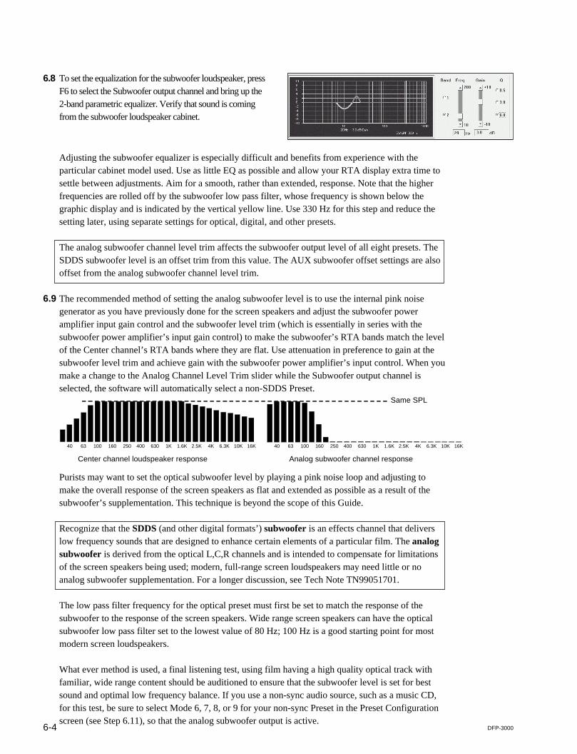
6.8 To set the equalization for the subwoofer loudspeaker, pressF6 to select the Subwoofer output channel and bring up the2-band parametric equalizer. Verify that sound is comingfrom the subwoofer loudspeaker cabinet.
Purists may want to set the optical subwoofer level by playing a pink noise loop and adjusting tomake the overall response of the screen speakers as flat and extended as possible as a result of thesubwoofer’s supplementation. This technique is beyond the scope of this Guide.
Recognize that the SDDS (and other digital formats’) subwoofer is an effects channel that deliverslow frequency sounds that are designed to enhance certain elements of a particular film. The analogsubwoofer is derived from the optical L,C,R channels and is intended to compensate for limitationsof the screen speakers being used; modern, full-range screen loudspeakers may need little or noanalog subwoofer supplementation. For a longer discussion, see Tech Note TN99051701.
The low pass filter frequency for the optical preset must first be set to match the response of thesubwoofer to the response of the screen speakers. Wide range screen speakers can have the opticalsubwoofer low pass filter set to the lowest value of 80 Hz; 100 Hz is a good starting point for mostmodern screen loudspeakers.
What ever method is used, a final listening test, using film having a high quality optical track withfamiliar, wide range content should be auditioned to ensure that the subwoofer level is set for bestsound and optimal low frequency balance. If you use a non-sync audio source, such as a music CD,for this test, be sure to select Mode 6, 7, 8, or 9 for your non-sync Preset in the Preset Configurationscreen (see Step 6.11), so that the analog subwoofer output is active.
Adjusting the subwoofer equalizer is especially difficult and benefits from experience with theparticular cabinet model used. Use as little EQ as possible and allow your RTA display extra time tosettle between adjustments. Aim for a smooth, rather than extended, response. Note that the higherfrequencies are rolled off by the subwoofer low pass filter, whose frequency is shown below thegraphic display and is indicated by the vertical yellow line. Use 330 Hz for this step and reduce thesetting later, using separate settings for optical, digital, and other presets.
The analog subwoofer channel level trim affects the subwoofer output level of all eight presets. TheSDDS subwoofer level is an offset trim from this value. The AUX subwoofer offset settings are alsooffset from the analog subwoofer channel level trim.
6.9 The recommended method of setting the analog subwoofer level is to use the internal pink noisegenerator as you have previously done for the screen speakers and adjust the subwoofer poweramplifier input gain control and the subwoofer level trim (which is essentially in series with thesubwoofer power amplifier’s input gain control) to make the subwoofer’s RTA bands match the levelof the Center channel’s RTA bands where they are flat. Use attenuation in preference to gain at thesubwoofer level trim and achieve gain with the subwoofer power amplifier’s input control. When youmake a change to the Analog Channel Level Trim slider while the Subwoofer output channel isselected, the software will automatically select a non-SDDS Preset.

6-5DFP-3000
40 63 100 160 250 400 630 1K 1.6K 2.5K 4K 6.3K 10K 16K
Center channel loudspeaker response
40 63 100 160 250 400 630 1K 1.6K 2.5K 4K 6.3K 10K 16K
Digital subwoofer (LFE) channel response
10dB higher SPL
This procedure, which requires an RTA, matches the playback gain of the SDDS Preset’ssubwoofer loudspeaker in the cinema to the playback response of the digital subwoofer (LFEloudspeaker) on the stage where the film’s sound track was mixed.
When evaluating the SDDS digital subwoofer (LFE) level, no listening test is entirely definitive,because the amount of energy in the LFE channel is a creative decision made when thesoundtrack of each film was mixed. For the same reason, the digital subwoofer (LFE) low passfilter setting has no relationship to the screen loudspeakers’ performance. It merely serves toexclude undesirable sound from the subwoofer (LFE) cabinet. The actual sounds reproduced onthe digital subwoofer (LFE) channel are determined by what was put there by the film’s soundmixer, as long as the filter frequency is not set so low as to remove sounds the mixer intended tobe included. Setting the digital subwoofer low pass filter frequency to 100 to 200 Hz should beacceptable and either setting should sound the same when actual film is exhibited; start with 160Hz. Subwoofer manufacturers may have specific recommendations for their cabinets.
Note that the result of a wideband SPL measurement of pink noise from the SDDS subwoofer(LFE) will depend on both the level Trim setting and the low pass filter Frequency setting. For aLPF frequency setting of 100 Hz, a wideband measurement made with an SPL meter will showapproximately 91 dB. Such a measurement should only be made to confirm that a correctlycalibrated theatre has not drifted, and cannot be used as a primary calibration measurement inplace of an RTA. Also remember that the analog subwoofer channel trim is effectively in serieswith the subwoofer amplifier’s input gain control. This means that an adjustment to the analogsubwoofer channel trim also affects the playback level of all digital subwoofer signals.
6.10 When adjusting the SDDS subwoofer (LFE) level offset, the SDDS Preset must be made theactive Preset. Select the preset manually with the Active Preset option under the Presets item inthe main screen menu bar and then selecting the SDDS Preset, or by clicking the appropriateradio button at the lower left of the main screen.8 is the default preset for SDDS. Press F6 to manually the subwoofer output channel. Alterna-tively, the software will automatically select the SDDS Preset when you have selected theSubwoofer output channel and click the SDDS Subwoofer Offset slider.
Use the SDDS Subwoofer Offset slider control andyour real time analyzer (RTA) to set 10 dB of in-band gain of the subwoofer’s bands as compared tothe previously calibrated Center speaker’s bands inthe region of its flat frequency response. Be sure toallow extra time for the low frequency bands tosettle to their final values.

6-6 DFP-3000
6.11 To set the surround channel delay and enable it foreach Preset, bring up the Preset Configurationscreen by selecting the Preset Configurationoption under the Presets item in the main screenmenu bar. This screen allows you to select eachPreset, make a level trim (to balance the relativelevel of each Preset), set a surround delay, and setthe subwoofer low pass filter (LPF) frequency forthat Preset.
In the latest versions of software you can also setsurround delay and subwoofer LPF frequency at themain screen, according to the output channel selected.
The surround channel delay can be set withelaborate science based on SMPTE 202M. How-ever, an easy rule-of-thumb approach is to set themilliseconds of delay for optical sources (NR2) toequal the length of the theatre (in feet) +10. Fordigital sources (SDDS) it should be set to 60 % ofthe optical surround delay.
6.12 If a cinema digital audio system is connected toone of the AUX inputs, you must set its corre-sponding subwoofer input level offset. Theplayback level of the subwoofer in today’s cinemadigital audio systems is offset by 10 dB. To accessthe AUX Input Calibration screen, select theAUX Inputs option from the A-chain item in themain screen menu bar. Click to select the correctoffset.
Note that the graphic and parametric equalizer settings adjust for the frequency response of eachof the loudspeaker cabinets in the theatre. This means they affect the output from all Presetinputs. The output channel level trims, including the analog subwoofer channel level trim, alsoaffect all Presets. These settings are retained in the DFP-D3000’s non-volatile memory as asingle set of overall adjustments to the playback system. Other settings, such as subwoofer lowpass filter frequency and surround speaker delay, may be unique to each format or signal source.These values are stored as individual settings for and within each of the eight Presets.
6-7DFP-3000
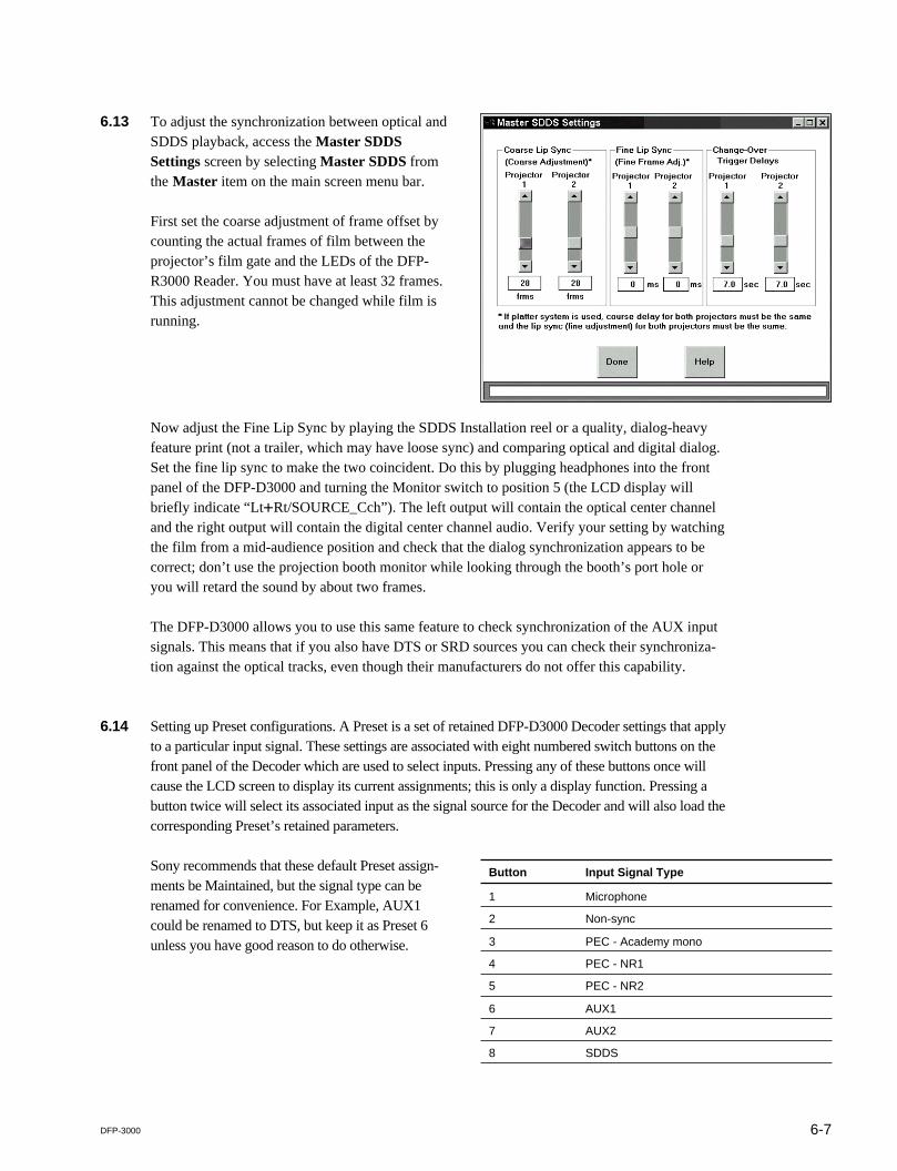
6.13 To adjust the synchronization between optical andSDDS playback, access the Master SDDSSettings screen by selecting Master SDDS fromthe Master item on the main screen menu bar.
First set the coarse adjustment of frame offset bycounting the actual frames of film between theprojector’s film gate and the LEDs of the DFP-R3000 Reader. You must have at least 32 frames.This adjustment cannot be changed while film isrunning.
Now adjust the Fine Lip Sync by playing the SDDS Installation reel or a quality, dialog-heavyfeature print (not a trailer, which may have loose sync) and comparing optical and digital dialog.Set the fine lip sync to make the two coincident. Do this by plugging headphones into the frontpanel of the DFP-D3000 and turning the Monitor switch to position 5 (the LCD display willbriefly indicate “Lt+Rt/SOURCE_Cch”). The left output will contain the optical center channeland the right output will contain the digital center channel audio. Verify your setting by watchingthe film from a mid-audience position and check that the dialog synchronization appears to becorrect; don’t use the projection booth monitor while looking through the booth’s port hole oryou will retard the sound by about two frames.
The DFP-D3000 allows you to use this same feature to check synchronization of the AUX inputsignals. This means that if you also have DTS or SRD sources you can check their synchroniza-tion against the optical tracks, even though their manufacturers do not offer this capability.
6.14 Setting up Preset configurations. A Preset is a set of retained DFP-D3000 Decoder settings that applyto a particular input signal. These settings are associated with eight numbered switch buttons on thefront panel of the Decoder which are used to select inputs. Pressing any of these buttons once willcause the LCD screen to display its current assignments; this is only a display function. Pressing abutton twice will select its associated input as the signal source for the Decoder and will also load thecorresponding Preset’s retained parameters.
Sony recommends that these default Preset assign-ments be Maintained, but the signal type can berenamed for convenience. For Example, AUX1could be renamed to DTS, but keep it as Preset 6unless you have good reason to do otherwise.
Button Input Signal Type
1 Microphone
2 Non-sync
3 PEC - Academy mono
4 PEC - NR1
5 PEC - NR2
6 AUX1
7 AUX2
8 SDDS

6-8 DFP-3000
The following parameters are stored in the DFP-D3000 for each Preset:Preset name (up to 12 user-entered characters)Input signal type (microphone, non-sync, PEC, AUX, or SDDS)Speaker output matrix (1 of 16 available matrix options)Fallback presets (for presets with AUX or SDDS input formats)Preset trim (fader offset for each Preset)EQ On/Off switchSurround delay On/Off switchSurround delaySub-woofer low pass filter frequencyFade in time (same for all non-sync presets)
To change these parameters, access the Preset Configuration screen from the Preset Configuration optionunder the Presets item in the main screen menu bar.
To re-configure a Preset, select the candidate Preset from the list of preset configurations in the PresetSelection area of the screen. After selecting the Preset, the various fields in the Preset Configuration areawill change to reflect its current configuration. If the selected Preset is a fallback assignment for other Presets(in the event their digital data becomes unavailable), such Presets will be highlighted in red in the PresetSelection area. If a change is made to the selected Preset which renders it invalid as a fallback for one of itshighlighted Presets, the setup software will display a warning and attempt to select another valid Preset toreplace the one you have modified. A list of changes will be displayed when the modified Preset’s newconfiguration is sent to the DFP-D3000 Decoder. If you are using firmware v3.0 or later, check with Sony tosee if changes have been made to functions available from the Preset Configuration screen.
The Preset Name edit box is used to change the name of a preset configuration. Alternate Preset namesare entirely up to the user, but cannot exceed 12 characters in length. The Setup Software automaticallyformats the name to center it in the DFP-D3000 front panel LCD display. To change the input signal type,click on the Preset Input edit box and select the signal type from a list that pops up. Sony suggests thatyou maintain the default selections.
6-9DFP-3000
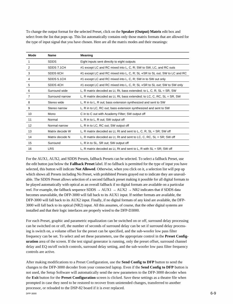
To change the output format for the selected Preset, click on the Speaker (Output) Matrix edit box andselect from the list that pops up. This list automatically contains only those matrix formats that are allowed forthe type of input signal that you have chosen. Here are all the matrix modes and their meanings:
Mode Name Meaning
1 SDDS Eight inputs sent directly to eight outputs
2 SDDS 7.1CH #1 except LC and RC mixed into L, C, R; SW to SW, LC, and RC outs
3 SDDS 6CH #1 except LC and RC mixed into L, C, R; SL +SR to SL out; SW to LC and RC
4 SDDS 5.1CH #1 except LC and RC mixed into L, C, R; SW in to SW out only
5 SDDS 4CH #1 except LC and RC mixed into L, C, R; SL +SR to SL out; SW to SW only
6 Surround wide L, R matrix decoded as Lt, Rt, bass extended; to L, C, R, SL = SR, SW
7 Surround narrow L, R matrix decoded as Lt, Rt, bass extended; to LC, C, RC, SL = SR, SW
8 Stereo wide L, R in to L, R out; bass extension synthesized and sent to SW
9 Stereo narrow L, R in to LC, RC out; bass extension synthesized and sent to SW
10 Mono C in to C out with Academy Filter; SW output off
11 Normal L, R in to L, R out; SW output off
12 Normal narrow L, R in to LC, RC out; SW output off
13 Matrix decode W L, R matrix decoded as Lt, Rt and sent to L, C, R, SL = SR; SW off
14 Matrix decode N L, R matrix decoded as Lt, Rt and sent to LC, C, RC, SL = SR; SW off
15 Surround L, R in to SL, SR out; SW output off
16 LRS L, R matrix decoded as Lt, Rt and sent to L, R with SL = SR; SW off
For the AUX1, AUX2, and SDDS Presets, fallback Presets can be selected. To select a fallback Preset, usethe edit button just below the Fallback Preset label. If no fallback is permitted for the type of input you haveselected, this button will indicate Not Allowed. Otherwise, when you click on it, a selection list will pop upwhich shows all Presets including No Preset, with prohibited Presets grayed out to indicate they are unavail-able. The SDDS Preset allows selection of a second fallback preset making it possible for all digital formats tobe played automatically with optical as an overall fallback if no digital formats are available on a particularreel. For example, the fallback sequence SDDS → AUX1 → AUX2 → NR2 indicates that if SDDS databecomes unavailable, the DFP-3000 will fall back to its AUX1 input. If neither formats are available, theDFP-3000 will fall back to its AUX2 input. Finally, if no digital formats of any kind are available, the DFP-3000 will fall back to its optical (NR2) input. All this assumes, of course, that the other digital systems areinstalled and that their logic interfaces are properly wired to the DFP-D3000.
For each Preset, graphic and parametric equalization can be switched on or off, surround delay processingcan be switched on or off, the number of seconds of surround delay can be set if surround delay process-ing is switch on, a volume offset for the preset can be specified, and the sub-woofer low pass filterfrequency can be set. To select and set these parameters, use the appropriate control in the Preset Config-uration area of the screen. If the test signal generator is running, only the preset offset, surround channeldelay and EQ on/off switch controls, surround delay setting, and the sub-woofer low pass filter frequencycontrols are active.
After making modifications to a Preset Configuration, use the Send Config to DFP button to send thechanges to the DFP-3000 decoder from your connected laptop. Even if the Send Config to DFP button isnot used, the Setup Software will automatically send the new parameters to the DFP-3000 decoder whenthe Exit button for the Preset Configuration screen is clicked. Save these settings as a theatre file whenprompted in case they need to be restored to recover from unintended changes, transferred to anotherprocessor, or reloaded to the DSP-82 board if it is ever replaced.

6-10 DFP-3000
6.15 At this point the DFP-3000 system needs only a few final adjustments. The Preset level trimscan be set according to the preferred methods of each cinema engineer. To access the trim of aPreset from the front panel, select the Preset by pressing its button twice and then press the Downarrow. Adjust the Master Volume control to change the preset trim in order to match the Preset tothe SDDS loudness level; when satisfied with the level, press the Up arrow to store the settingand return to normal operation. Some may chose to adjust external non-sync distribution amplifi-ers to achieve the desired level and leave the DFP-D3000 non-sync trim at 0.0 dB. If the screenhas additional digital formats, play a quad format feature and block the LEDs of the variousreaders and use the DFP-D3000’s fallback system to automatically switch between formats,comparing loudness by listening to the booth monitor. This allows checking the fallback wiringas well as the preset level matching. Normally, it is best to use output trims on the other digitalplayers to achieve 85 dB SPL at each speaker in the same manner as was done for the SDDSformat with the DFP-D3000 (using pink noise and an SPL meter), but the Preset trims can also beused if convenient. When making this test, blocking the DFP-R3000 reader’s LEDs will allowyou to confirm operation of the SDDS ACM (Analog Concealment Mode) fallback to optical orother preset.
The bypass level setting is made by adjusting two trimmer potentiometers (for Lt and Rt) locatedat the left of the lower circuit board inside the DFP-D3000. These are adjusted to produce thesame output level to L and R when the unit is powered Off while playing a pink noise loopthrough the optical inputs. Remove two silver screws at the right of the front panel and swing itaside to reach these two trim controls.
The single HI (hearing impaired) output level trim potentiometer is located to the right of thebypass level trim controls and is marked HI on the circuit board. It adjusts the HI output from .7to 7 V at its rear panel PHONES connector.
APR-34 rev 11 circuit board (lowest of 3)
APR-34 rev 12 circuit board (lowest of 3)
Lt Rt HI

7-1DFP-3000
7. Overall systems check and listening test.
The basic installation, alignment, and test of the DFP-3000 Cinema Processor System is now complete.Before signing off on the job, the installer will want to play familiar reference films and listen in thehouse to confirm that all is well. It might also be a good idea to repeat the synchronization test of 6.13with actual film. Adjust the fine lipsync if necessary; using the front panel for this will require the“SDDS” password.


8-1DFP-3000
8. Troubleshooting
Experienced cinema engineers will have their own methods and styles of troubleshooting. Here are sometips that relate to the SDDS format and the DFP-3000 system. Check with Sony Cinema Products for aTech Note with more details.
Problems with playing SDDS.First, ensure that the film actually has SDDS tracks on it. These tracks are the light blue or cyan areas atthe outside of both rows of sprocket holes. The dark blue spots are very small, but you should be able tosee a fine granularity in this area-not just a smooth blue area.
The first indication of problems playing SDDS titles due to poor print quality or dirty optics may beflickering of the film title displayed on the Decoder’s LCD display (SDDS Fader Automation must beenabled to display the film title). Clean the Reader optics.
The SYSTEM OK LED on the DFP-D3000 front panel indicates that battery power is OK and that theunit is properly communicating with its Reader. The DATA PRESENT LED will flash if film is runningthrough the Reader at 24 frames/second (+/- 5%) and comes on solidly when SDDS data is being receivedfrom the Reader.
Next to the MASTER VOLUME fader is a switch labeled MUTING. If this switch is illuminated, sounddoes not appear at the outputs. Press it to restore sound output.
The REMOTE LED indicates that the Decoder is being controlled through its serial port, at which timethe front panel controls and most of the AUTOMATION connector’s inputs are locked out. Be sure yourlaptop software is “disconnected”.
The Reader will turn on its bright red LEDs when the black sprocket roller is turning and it is receivingpower through its cable. If the DFP-D3000 is powered and you don’t see LEDs on the Reader, check thatthe Reader cable is plugged in and is not damaged.
The matrix modes described in section 6.14 can be complicated. If you have channels missing, particular-ly the subwoofer, on a certain Preset, check that you have selected the desired matrix mode for thatPreset.
The EXT FADER button on the front panel of the DFP-D3000 enables a remote fader. If this function isactive (as indicated by its illuminated switch), the MASTER VOLUME control becomes inoperative andthe external fader takes over. Don’t use this switch unless an external fader is actually connected or yoursound may be muted.
The PROJECTOR LEDs indicate which projector’s DFP-R3000 Reader is selected in a changeoverenvironment, using the rear Automation connector pins. Be sure the correct Reader is selected. Opticalsoundtrack reader selection is also selected at the Automation connector, but has no bearing on these LEDindicators.

8-2 DFP-3000
Sony Cinema Products EuropeEngineering Services Division Europe, Middle East, Africa25 Golden SquareLondon W1R 6LU, EnglandPhone: +44 171 533 1475Fax: +44 171 533 1590Hours: 9:00am to 6:00pm GMT
Sony System Service, TokyoTokki Service Center Japan7-22-17 TOC Building 8FNishi Gotanda, Shinagawa-kuTokyo, 141-0031, JapanPhone: +81 3 5436 7510Fax: +81 3 5436 7519Hours: 9:00am to 6:00pm JST
Sony Cinema Products CorporationEngineering Services Division West Coast (USA)10950 W. Washington Boulevard Culver City CA 90232, USAPhone: +1 310 244-3484Fax: +1 310 244-0484Hours: 8:30am to 5:00pm PSTWith 24-hour telephone responsee-mail: [email protected]
Sony Cinema Products CorporationEngineering Services Division East Coast (USA)123 West Tyron AvenueTeaneck NJ 07666, USAPhone: +1 201 833-5778Fax: +1 201 833-5860Hours: 8:30am to 5:00pm EST
Problems playing other digital formats.For other digital systems to play automatically according to fallback settings or when their Preset isselected, their analog audio outputs must be correctly wired to an AUX input and their logic outputs mustbe correctly wired to the AUTOMATION connector of the DFP-D3000. Basically Pin 34 must begrounded for AUX1 to play and Pin 35 must be grounded to play AUX2, otherwise selecting thesePresets will play only their specified fallback sources. The same effect can be achieved in software byselecting “No Fallback” (indicated by *) as the fallback for AUX 1 or 2. This will prevent them from evergoing to their fallback presets, but will also preempt selecting optical (NR2) as a fallback in the eventtheir data fails.
If you lose sound during a show you can place the DFP-3000 into bypass by turning off its mains powerat the front panel; an orange LED in the SELECT switch will come on unless the bypass power supply isnot connected. When running off the bypass supply, the Decoder will play in stereo from its optical input,but without noise reduction or matrix decoding. If you lose digital sound for brief periods or if you areunable to play optical soundtracks, the first thing to ensure is that the exciter lamp is working. See TechNote TN99111901 for help with a forward scan optical reader system.
Use the front panel HEADPHONE output and its MONITOR SELECT switch as a quick troubleshootingaid. The signal source that is selected will be displayed on the LCD screen for five seconds after youmove the selector switch to a new position.
In the event you have difficulty.Sony Cinema Products operates service offices around the world. Contact us for assistance any thefollowing locations:

9-1DFP-3000
9. Appendix
Useful references for installing the system are described here. We also provide usefultechnical information for installing the DFP-3000 system. Please contact SONY Service
Center for more information.
9.1 DFP-D3000 Rear Panel Connector Pin AssignmentSYSTEM (25-pin D-Sub Male)MONITOR (25-pin D-Sub Male)AUX1, AUX 2 (25-pin D-Sub Female)
(all according to the THXTM convention)
Pin Signal
1 Left GND (ground)
2 Left HOT (+, or in-phase of balanced signal)
3 Left Center COLD (_, or out-of-phase of balanced signal)
4 Center GND (ground)
5 Center HOT (+, or in-phase of balanced signal)
6 Right Center COLD (_, or out-of-phase of balanced signal)
7 Right GND (ground)
8 Right HOT (+, or in-phase of balanced signal)
9 Surround Left GND (ground)
10 Surround Left COLD (_, or out-of-phase of balanced signal)
11 Surround Right COLD (_, or out-of-phase of balanced signal)
12 Subwoofer, LFE, COLD (_, or out-of-phase of balanced signal)
13 Subwoofer, LFE, GND (ground)
14 Left COLD (_, or out-of-phase of balanced signal)
15 Left Center GND (ground)
16 Left Center HOT (+, or in-phase of balanced signal)
17 Center COLD (_, or out-of-phase of balanced signal)
18 Right Center GND (ground)
19 Right Center HOT (+, or in-phase of balanced signal)
20 Right COLD (_, or out-of-phase of balanced signal)
21 No connection
22 Surround Right GND (ground)
23 Surround Left HOT (+, or in-phase of balanced signal)
24 Surround Right HOT (+, or in-phase of balanced signal)
25 Subwoofer, LFE, HOT (+, or in-phase of balanced signal)

9-2 DFP-3000
MIC INPUT (9-pin D-Sub Female)
Pin Signal
1 Mic 1 GND (ground)
2 Mic 1 HOT (+, or in-phase of balanced signal)
3 No connection
4 Mic 2 GND (ground)
5 Mic 2 HOT (+, or in-phase of balanced signal)
6 Mic 1 COLD (_, or out-of-phase of balanced signal)
7 No connection
8 No connection
9 Mic 2 COLD (_, or out-of-phase of balanced signal)
OPTICAL 1, OPTICAL 2 (9-pin D-Sub Female)
Pin Signal
1 Left GND (ground)
2 Left HOT (+, or in-phase of balanced signal)
3 No connection
4 Right GND (ground)
5 Right HOT (+, or in-phase of balanced signal)
6 Left COLD (_, or out-of-phase of balanced signal)
7 No connection
8 No connection
9 Right COLD (_, or out-of-phase of balanced signal)
PHONES (9-pin D-Sub Female)
Pin Signal
1 GND (ground)
2 GND (ground)
3 No connection
4 Headphone Left
5 Headphone Right
6 Mono Hearing Impaired
7 Mono Hearing Impaired
8 No connection
9 Headphone GND (ground)

9-3DFP-3000
REMOTE LEVEL CONTROL (Remote Fader) (9-pin D-sub Female)
Pin Signal
1 Remote potentiometer ground (min gain end)
2 MAIN FADE (input)
3 No connection
4 No connection
5 No connection
6 Remote potentiometer wiper
7 Remote potentiometer DC drive (max gain end)
8 Remote Tally output for LED
9 GND (ground)
AUTOMATION (37-pin D-Sub Female)Pins in bold type changed after v2.63 firmware.
Pin Function Signal
1 Chassis Ground GND
2 Projector 1 Motor Start Input: Low = MOTOR 1 RUNNING
3 Master Mute command Input pulse: Low = MUTE or UNMUTE
4 Preset 1 Select (and tally pulldown) Input pulse: Low = SELECT
5 Preset 2 Select (and tally pulldown) Input pulse: Low = SELECT
6 Preset 3 Select (and tally pulldown) Input pulse: Low = SELECT
7 Preset 4 Select (and tally pulldown) Input pulse: Low = SELECT
8 Preset 5 Select (and tally pulldown) Input pulse: Low = SELECT
9 Preset 6 Select (and tally pulldown) Input pulse: Low = SELECT
10 Preset 7 Select (and tally pulldown) Input pulse: Low = SELECT
11 Preset 8 Select (and tally pulldown) Input pulse: Low = SELECT
12 Motor 1 Output tally: Low = MOTOR 1 RUNNING
13 Motor 2 Output tally: Low = MOTOR 2 RUNNING
14, 15 Logic Common 0 V
16, 17 Tally Common 0 V
18 Optical Change Over Command Input: Low = PEC 2, High = PEC 1
19 Optical Change Over Tally Output tally: Low = PEC 2 selected
20 Projector 1 Tally Output tally: Low = SDDS Reader 1 selected
21 Projector 2 Tally Output tally: Low = SDDS Reader 2 selected
22 Master Mute Tally Output tally: Low = Master muted
23 Pink Noise Input: Low = ON
24-29 Reserved No Connections
30 +5 V Power
31 +5 V Power
32 SDDS Data OK (any preset active) Output pulse: Low = SDDS OK
33 Projector 2 Motor Start Input: Low = MOTOR 2 RUNNING
34 AUX1 Digital Data OK Input: Low = Data OK
35 AUX2 Digital Data OK Input: Low = Data OK
36 SDDS Data not OK Output pulse: Low = SDDS NG
37 Reserved No Connection
9-4 DFP-3000
9.2 DFP-D3000 Input/Output LevelThe DFP-D3000 input/output levels are as follows:
AUX input reference level:The reference level is _8.2 dBu (= 300 mV). The signal level can be increased for other channels only forthe Sub Woofer channel input. (Select from 0 dB, +6 dB, +8 dB, +10 dB).Set this item from the setup software.
Non-Sync input reference level:Select from +4 dBu reference, _10 dBu reference, and _16 dBu. (Set from the setup software.)
Microphone 1 input reference level:This input can be used not only as the microphone input but as the line input (monaural) as well.The level of the microphone input can be adjusted within the range of _20 dBu and _60 dBu.During line input, the level can be selected from +4 dBu reference, _10 dBu reference, and _16 dBureference. (Set from the setup software.)The default values are _50 dBu for the microphone input, and _10 dBu for the line input.
Microphone 2 input reference level:The level of the microphone input can be adjusted within the range of _20 dBu and _60 dBu (1 dB step).The default value is _50 dBu.
Phantom power (+48 V) can be supplied for both Microphone inputs 1 and 2.
PEC input reference level:If A-chain automatic adjustment is performed using the reference film recording the 880 Hz sine wave(film recorded with Dolby Tone) in the DFP-D3000, the DFP-D3000 meter will be set to _20 dB (20 dBbelow the maximum level of the digital signal processing) when the film reference signal is played back.
Reference level of the digital unit:20 dB (_20 dBFs) below the maximum level (0 dBFs) of digital signal processing. In digital signalprocessing, basically _20 dBFs will be directly output to the output if the equalizer level, trim level, etc.have not been adjusted
Audio output level (SYSTEM OUTPUT, MONITOR OUTPUT)Select from the _16 dB reference or _10 dBu reference. However the system can handle the +4 dBureference output.

9-5DFP-3000
9.3 Changeover SettingsThe following signals must be connected to control changeover from the projector.
. Connect the Motor 1 Start signal (output) of the projector to the Pin 1 Proj. 1 motor start terminal(input) of the DFP-D3000 Automation connector. (ON at low level)
. Connect the Motor 2 Start signal (output) of the projector to the Pin 33, Proj. 2 motor start terminal(input) of the DFP-D3000 Automation connector. (ON at low level)
. Connect the Change over command output (gate switching control signal of the projector) of theprojector to the Pin 18, C/O CMD IN terminal of the DFP-D3000 Automation connector. (At the Lowlevel, Projector 2 is selected. At the High level, Projector 1 is selected.)
. Connect the Ground signal of the projector to Pins 14 to 17 of the DFP-D3000 Automation connector(Logic common or Tally common)
To control the changeover from the projector, set the time from the start of the motor of the projector tochangeover to 7 seconds. Also set the Ramp Time (start up time) to less than 3 seconds (the faster thebetter).
The following shows the connections for using the DFP-D3000 data detection function for controlling theDolby surround decoder DA-20 changeover operations.
DFP-D3000 Automation Connector DA-20 Motor start connector(DB37 F, Cable M) (DB9 F, Cable M)
Pin 12, Motor 1 (start command out) Pin 1, Motor start Proj. 1 (Input)
Pin 13, Motor 2 (start command out) Pin 9, Motor start Proj. 2 (Input)
Pin 16, Tally Common Pin 5, GND
To perform changeover operations, be sure to adjust the lip sync of both projectors. Details of the lip syncadjustment are provided in Section 6.11 of this manual.
The following shows the system configuration and connections of the controller during basic changeover.

9-6 DFP-3000
9.4 Settings for using DFP-D3000 as DFP-D2000The DFP-D3000 operations must be set appropriately using the setup software.
9.4.1 ConditionsWhen the DFP-D3000 has been added to the existing cinema processor master, do not turn off thepower of the DFP-D3000 while running the film (including film which does not record SDDS).No sounds will be output including the existing system if turned OFF.
9.4.2 Connections and Settings when Connecting the Output of an Existing System
1. Connecting the systemInput signals from an existing system to the AUX1 input or AUX2 input for the audio system.At the same time, connect the theater amplifier to SYSTEM OUT. Also connect the SDDS READER(DFP-D3000) to the DFP-D3000.Automation connection is required if changeover is to be performed or if switching to other digitalformats using the DFP-D3000. The connections are as follows.
Dolby Digital SoundProcessor (DolbyLaboratories, IncDA-20, DA-10)
(Dolby Laboratories, Inc.CP-65 etc. )
9-7DFP-3000
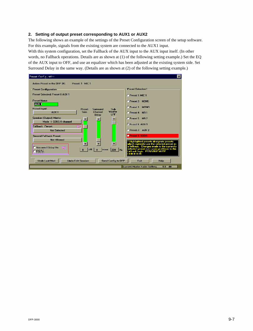
2. Setting of output preset corresponding to AUX1 or AUX2The following shows an example of the settings of the Preset Configuration screen of the setup software.For this example, signals from the existing system are connected to the AUX1 input.With this system configuration, set the Fallback of the AUX input to the AUX input itself. (In otherwords, no Fallback operations. Details are as shown at (1) of the following setting example.) Set the EQof the AUX input to OFF, and use an equalizer which has been adjusted at the existing system side. SetSurround Delay in the same way. (Details are as shown at (2) of the following setting example.)
9-8 DFP-3000
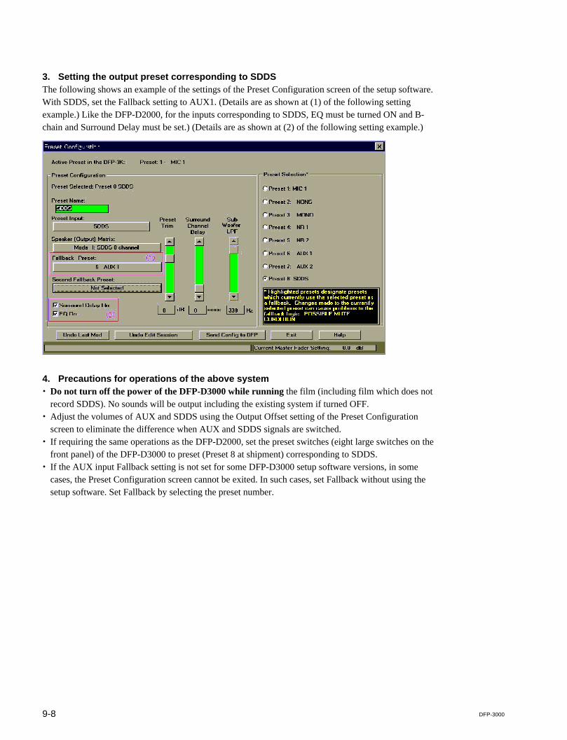
3. Setting the output preset corresponding to SDDSThe following shows an example of the settings of the Preset Configuration screen of the setup software.With SDDS, set the Fallback setting to AUX1. (Details are as shown at (1) of the following settingexample.) Like the DFP-D2000, for the inputs corresponding to SDDS, EQ must be turned ON and B-chain and Surround Delay must be set.) (Details are as shown at (2) of the following setting example.)
4. Precautions for operations of the above system. Do not turn off the power of the DFP-D3000 while running the film (including film which does not
record SDDS). No sounds will be output including the existing system if turned OFF.. Adjust the volumes of AUX and SDDS using the Output Offset setting of the Preset Configuration
screen to eliminate the difference when AUX and SDDS signals are switched.. If requiring the same operations as the DFP-D2000, set the preset switches (eight large switches on the
front panel) of the DFP-D3000 to preset (Preset 8 at shipment) corresponding to SDDS.. If the AUX input Fallback setting is not set for some DFP-D3000 setup software versions, in some
cases, the Preset Configuration screen cannot be exited. In such cases, set Fallback without using thesetup software. Set Fallback by selecting the preset number.

9-9DFP-3000
9.4.3 Connections and Settings When Connecting to the Input of the Existing System
1. Connections of the systemFor the audio system, connect SYSTEM OUT to the external input of the existing cinema processor.Connect the SDDS reader (DFP-R3000) to the DFP-D3000.Automation connection or connection of the AUX input is required if changeover is to be performed or ifswitching to other digital formats using the DFP-D3000.The following shows an example of connections.
Dolby Digtal SoundProcessor(Dolby Laboratories, Inc.DA-20, DA-10)
(Dolby Laboratories,Inc. CP-65 etc.)
DFP-D3000 Cinema Sound
Power
Auxiliary
InputOpt1 (&Opt2)
Reader 1 (&Reader 2)
Auxiliary
Automation
Input
System
Output
Mainoutput Amp
Dolby DigtalReader
AnalogReader
DFP-R3000
Processor

9-10 DFP-3000
2. Setting of output preset corresponding to SDDSThe following shows an example of the settings of the Preset Configuration of the setup software at thistime.Set the Fallback of the SDDS to “No Fallback”. (Refer to (1) in the example of settings screen.)With this system configuration, do not adjust the B-chain of the DFP-D3000 in order to use the B-chainfunction of the existing cinema microprocessor. To prevent accidents, set the EQ setting at the Presetsettings to OFF. (Refer to (2) in the example of settings screen.) To send signals to the AUX input of theDFP-D3000 from another cinema processor, the AUX input connected to that signal can be selected asthe Fallback setting.
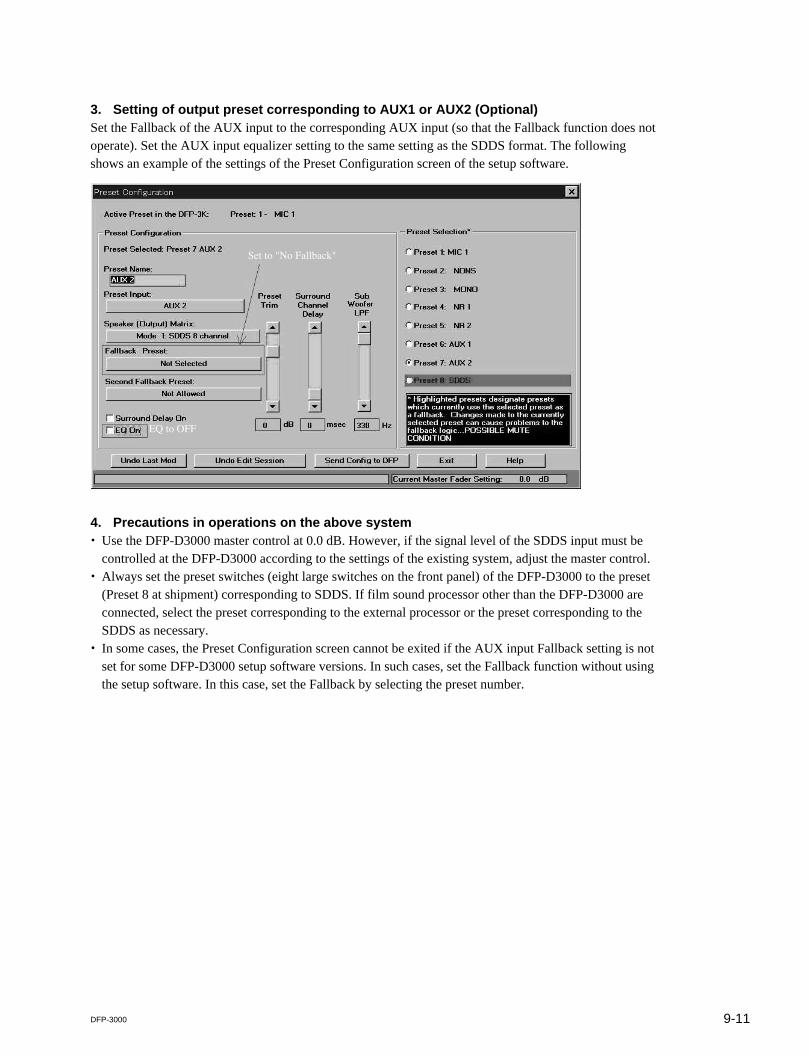
9-11DFP-3000
3. Setting of output preset corresponding to AUX1 or AUX2 (Optional)Set the Fallback of the AUX input to the corresponding AUX input (so that the Fallback function does notoperate). Set the AUX input equalizer setting to the same setting as the SDDS format. The followingshows an example of the settings of the Preset Configuration screen of the setup software.
4. Precautions in operations on the above system. Use the DFP-D3000 master control at 0.0 dB. However, if the signal level of the SDDS input must be
controlled at the DFP-D3000 according to the settings of the existing system, adjust the master control.. Always set the preset switches (eight large switches on the front panel) of the DFP-D3000 to the preset
(Preset 8 at shipment) corresponding to SDDS. If film sound processor other than the DFP-D3000 areconnected, select the preset corresponding to the external processor or the preset corresponding to theSDDS as necessary.
. In some cases, the Preset Configuration screen cannot be exited if the AUX input Fallback setting is notset for some DFP-D3000 setup software versions. In such cases, set the Fallback function without usingthe setup software. In this case, set the Fallback by selecting the preset number.
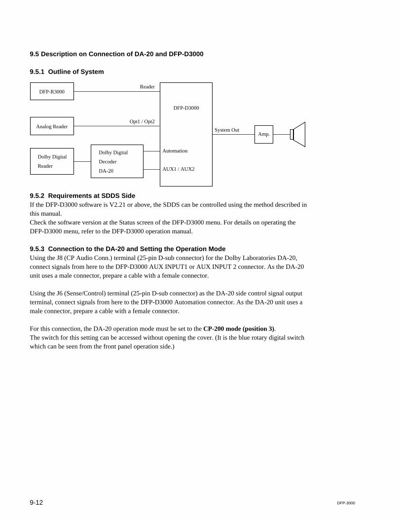
9-12 DFP-3000
9.5 Description on Connection of DA-20 and DFP-D3000
9.5.1 Outline of System
9.5.2 Requirements at SDDS SideIf the DFP-D3000 software is V2.21 or above, the SDDS can be controlled using the method described inthis manual.Check the software version at the Status screen of the DFP-D3000 menu. For details on operating theDFP-D3000 menu, refer to the DFP-D3000 operation manual.
9.5.3 Connection to the DA-20 and Setting the Operation ModeUsing the J8 (CP Audio Conn.) terminal (25-pin D-sub connector) for the Dolby Laboratories DA-20,connect signals from here to the DFP-D3000 AUX INPUT1 or AUX INPUT 2 connector. As the DA-20unit uses a male connector, prepare a cable with a female connector.
Using the J6 (Sense/Control) terminal (25-pin D-sub connector) as the DA-20 side control signal outputterminal, connect signals from here to the DFP-D3000 Automation connector. As the DA-20 unit uses amale connector, prepare a cable with a female connector.
For this connection, the DA-20 operation mode must be set to the CP-200 mode (position 3).The switch for this setting can be accessed without opening the cover. (It is the blue rotary digital switchwhich can be seen from the front panel operation side.)
Amp.
Dolby Digital
Decoder
DA-20
DFP-D3000
Automation
System Out
AUX1 / AUX2
DFP-R3000
Analog Reader
Dolby Digital
Reader
Reader
Opt1 / Opt2
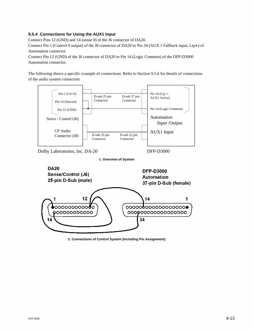
9-13DFP-3000
9.5.4 Connections for Using the AUX1 InputConnect Pins 12 (GND) and 14 (sense 0) of the J6 connector of DA20.Connect Pin 1 (Control 0 output) of the J6 connector of DA20 to Pin 34 (AUX 1 Fallback input, Lip+) ofAutomation connector.Connect Pin 12 (GND) of the J6 connector of DA20 to Pin 14 (Logic Common) of the DFP-D3000Automation connector.
The following shows a specific example of connections. Refer to Section 9.5.6 for details of connectionsof the audio system connectors
1. Overview of System
2. Connections of Control System (Including Pin Assignment)
Pin 1 (Ctri 0)
Pin 14 (Senced)
Pin 12 (GND)
Pin 34 (Lip +.AUX1 Active)
Pin 14 (Logic Common)
Automation Input /Output
AUX1 Input
D-sub 25 pinConnector
D-sub 37 pinConnector
D-sub 25 pinConnector
D-sub 25 pinConnector
Dolby Laboratories, Inc. DA-20 DFP-D3000
CP AudioConnector (J8)
Sence / Contorl (J6)

9-14 DFP-3000
For this connection, open the Preset Configuration screen of the DFP-D3000 setup software, and set thePrimary Fallback setting to “NR2” in the preset corresponding to the AUX1 input. (Check the enclosedpart of the screen.)
Preset Configuration Screen (When AUX1 is selected)
If Fallback must be performed in the order of AUX1 input and Analog input from SDDS, set the PrimaryFallback setting to “AUX1” in the preset corresponding to the SDDS. (Check the enclosed part of thescreen.)
Preset Configuration Screen (When SDDS is selected)
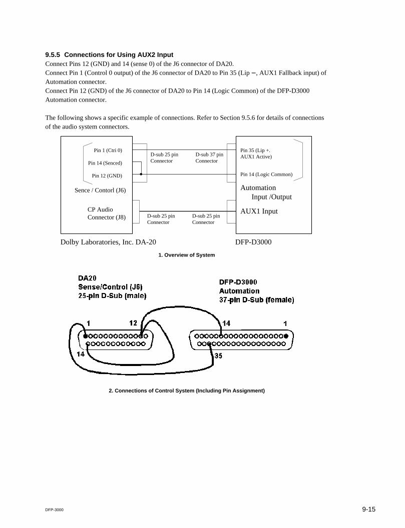
9-15DFP-3000
9.5.5 Connections for Using AUX2 InputConnect Pins 12 (GND) and 14 (sense 0) of the J6 connector of DA20.Connect Pin 1 (Control 0 output) of the J6 connector of DA20 to Pin 35 (Lip _, AUX1 Fallback input) ofAutomation connector.Connect Pin 12 (GND) of the J6 connector of DA20 to Pin 14 (Logic Common) of the DFP-D3000Automation connector.
The following shows a specific example of connections. Refer to Section 9.5.6 for details of connectionsof the audio system connectors.
1. Overview of System
2. Connections of Control System (Including Pin Assignment)
Pin 1 (Ctri 0)
Pin 14 (Senced)
Pin 12 (GND)
Pin 35 (Lip +.AUX1 Active)
Pin 14 (Logic Common)
Automation Input /Output
AUX1 Input
D-sub 25 pinConnector
D-sub 37 pinConnector
D-sub 25 pinConnector
D-sub 25 pinConnector
Dolby Laboratories, Inc. DA-20 DFP-D3000
CP AudioConnector (J8)
Sence / Contorl (J6)

9-16 DFP-3000
For this connection, open the Preset Configuration screen of the DFP-D3000 setup software, and set thePrimary Fallback setting to “NR2” in the preset corresponding to the AUX2 input.
Preset Configuration Screen (When AUX2 is selected)
If Fallback must be performed in the order of AUX2 input and Analog input from SDDS, set the PrimaryFallback setting to “AUX2” in the preset corresponding to the SDDS.
Preset Configuration Screen (When SDDS is selected)

9-17DFP-3000
9.5.6 Audio Connecting the DA-20 and DFP-D3000For details of the connection, refer to the following table.
DFP-D3000 AUX Input 1/2 DA-20 CP Audio Conn. J8(DB25, F/Cable M) (DB25 M/Cable F)
1 Left Ground N.C.
2 Left Hot 14 Left out
3 Left Center Cold N.A.
4 Center Ground N.C.
5 Center Hot 20 Center Out
6 Right Center Cold N.A.
7 Right Ground N.C.
8 Right Hot 17 Right Out
9 Left Surround Ground N.C.
10 Left Surround Cold 4 AGND
11 Right Surround Cold 3 AGND
12 Sub Woofer Cold 12 AGND
13 Sub Woofer Ground N.C.
14 Left Cold 1 AGND
15 Left Center Ground N.A.
16 Left Center Hot N.A.
17 Center Cold 8 AGND
18 Right Center Ground N.A.
19 Right Center Hot N.A.
20 Right Cold 5 AGND
21 N.C. N.C.
22 Right Surround Ground N.C.
23 Left Surround Hot 15 Left Surround Out
24 Right Surround Hot 2 Right Surround Out
25 Sub Woofer Hot 24 Sub Woofer Out
N.A.: No corresponding function. N.C.: Not connected.
nAll audio grounds must be connected to the shield side of each twisted pair cables at the DFP-D3000.
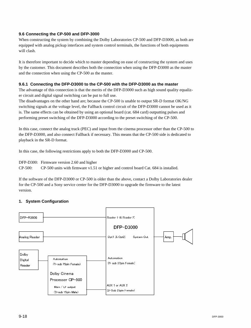
9-18 DFP-3000
9.6 Connecting the CP-500 and DFP-3000When constructing the system by combining the Dolby Laboratories CP-500 and DFP-D3000, as both areequipped with analog pickup interfaces and system control terminals, the functions of both equipmentswill clash.
It is therefore important to decide which to master depending on ease of constructing the system and usesby the customer. This document describes both the connection when using the DFP-D3000 as the masterand the connection when using the CP-500 as the master.
9.6.1 Connecting the DFP-D3000 to the CP-500 with the DFP-D3000 as the masterThe advantage of this connection is that the merits of the DFP-D3000 such as high sound quality equaliz-er circuit and digital signal switching can be put to full use.The disadvantages on the other hand are; because the CP-500 is unable to output SR-D format OK/NGswitching signals at the voltage level, the Fallback control circuit of the DFP-D3000 cannot be used as itis. The same effects can be obtained by using an optional board (cat. 684 card) outputting pulses andperforming preset switching of the DFP-D3000 according to the preset switching of the CP-500.
In this case, connect the analog track (PEC) and input from the cinema processor other than the CP-500 tothe DFP-D3000, and also connect Fallback if necessary. This means that the CP-500 side is dedicated toplayback in the SR-D format.
In this case, the following restrictions apply to both the DFP-D3000 and CP-500.
DFP-D300: Firmware version 2.60 and higherCP-500: CP-500 units with firmware v1.51 or higher and control board Cat. 684 is installed.
If the software of the DFP-D3000 or CP-500 is older than the above, contact a Dolby Laboratories dealerfor the CP-500 and a Sony service center for the DFP-D3000 to upgrade the firmware to the latestversion.
1. System Configuration

9-19DFP-3000
2. Logic wiring connections
DFP-D3000 Automation I/O Connector CP-500 Automation Connector(D-sub Connector, 37 pin, Female) (D-sub Connector, 25 pin, Female)
Pin No. Function Pin No. Function
Pin 8 Preset 5 Select (NR2) Pin 3 SK3 format select (Dolby SR)
Pin 9 Preset 6 Select (AUX 1) Pin 4 SK4 format select (Dolby Digital)
Pin 14 Logic Common Pin 12 Ground
Pin 11 Preset 8 Select (SDDS) Pin 6 SK6 format select (Non Sync 1)- Shorted to -
Pin 32 SDDS data OK
Pin 36 SDDS data not OK Pin 2 SK2 format select (Dolby A)
Pin 15 Logic Common- Shorted to -
Pin 34 AUX1 Digital Data OK
3. Audio wiring connections
DFP-D3000 AUX input 1/2 CP-500 Main / LF output connector(D-sub connector, 25 pin, Female) (15 pin Phoenix type, Male)
Pin No. Function Pin No. Function
Pin 1 Left Ground _ No Connection
Pin 2 Left Hot (+) 1 Left Channel
Pin 4 Center Ground _ No Connection
Pin 5 Center Hot (+) 5 Center Channel
Pin 7 Right Ground _ No Connection
Pin 8 Right Hot (+) 3 Right Channel
Pin 9 Left Surround Ground _ No Connection
Pin 10 Left Surround Cold (_) 8 Signal Ground
Pin 11 Right Surround Cold (_) 10 Signal Ground
Pin 12 Subwoofer Cold (_) 12 Signal Ground
Pin 13 Subwoofer Ground _ No Connection
Pin 14 Left Cold (_) 2 Signal Ground
Pin 17 Center Cold (_) 6 Signal Ground
Pin 20 Right Cold (_) 4 Signal Ground
Pin 22 Right Surround Ground _ No Connection
Pin 23 Left Surround Hot (+) 7 Left Surround Channel
Pin 24 Right Surround Hot (+) 9 Right Surround Channel
Pin 25 Subwoofer Hot (+) 11 Subwoofer Channel
nThe inputs of the DFP-D3000 are professionally balanced, whereas the outputs of the CP-500 are not.Therefore shielded wires should be connected to all DFP-D3000 audio grounds.
9-20 DFP-3000
4. Procedures for setting up the CP-500First, confirm that the CP-500 is equipped with firmware version 1.51 or higher.
Next, enable the “Auto Digital” function by referring to the CP-500 Installation Manual. The sourceformat of the “Auto Digital” function should be set to Dolby A (SK2), and the target format to DolbyDigital (SK4). It is crucial that Dolby SR (SK3) is not assigned as a source format of the “Auto Digital”function. These instructions assume that the CP-500 preset is configured for Dolby A on SK2, Dolby SRon SK3, Dolby Digital on SK4 and Non Sync 1 on SK6.
Set the level of all output channels of the CP-500 to the DFP-D3000 AUX Port input reference level.(_8.2 dBu. This value is equivalent to _10 dBV or 300 mV.)
During operation, ensure that the master fader on the CP-500 is disabled or kept at 7.0 at all times.
5. Setting up the DFP-3000First, confirm that the DFP-D3000 is equipped with firmware version 2.60 or higher.
The DFP-D3000 is configured for SDDS on Preset 8 and that Dolby Digital is on Preset 6 (using theAUX1 input). We recommend that you don’t change Preset assignments from the defaults unless there isa strong requirement for doing so. If Preset assignments are to be changed, we recommend setting up thetheatre completely and confirming that all is working correctly before making the reassignments.
In this system, set the fallback structure corresponding to the SDDS input (Preset 8) of the DFP-3000 asfollows. The Preset Configuration screen of the Setup software will display as follows. ((1) of the follow-ing diagram.)
SDDS → [AUX 2] → NR2 (Set the AUX2 input when using the DTS, etc.)

9-21DFP-3000
If equalizer adjustments for B-chain have been performed on the CP-500, set the equalizer setting of thecorresponding preset (Preset 6) of the DFP-D3000 to “OFF”. In the same way, if the Surround Delay isset at the CP-500 side, set the DFP-D3000 Surround Delay to “OFF”. The Preset Configuration screen ofthe Setup software will display as follows. ((2) of the following diagram.)Generally, as the equalizer and delay quality of the DFP-3000 are better than CP-500, use the DFP-3000.The preset fallback setting corresponding to the CP-500 can be left at the default setting. (Because it isfixed to prevent hardware fallback.)

9-22 DFP-3000
6. Using as the changeover systemWhen using the system combining the DFP-D3000 and CP-500 in the changeover format, it is necessaryto supply the motor start pulse and change over command signals for the CP-500 as well. Therefore, addthe following signals to the control signal line and connect the cables.
Projector DFP-D3000 Automation I/O Connector CP-500 Motor Start Connector(D-sub Connector, 37pin, Female) (D-sub Connector, 9pin, Female)
Signal Pin No. Function Pin No. Function
Projector 1 Motor Start Pin 12 Motor 1 Pin 1 Motor Start Projector 1
Projector 2 Motor Start Pin 13 Motor 2 Pin 9 Motor Start Projector 2
Picture Gate Select Pin 19 C/O command, tally Pin 3 Change Over Relay
Common Pin 16 Tally Common Pin 5 GND
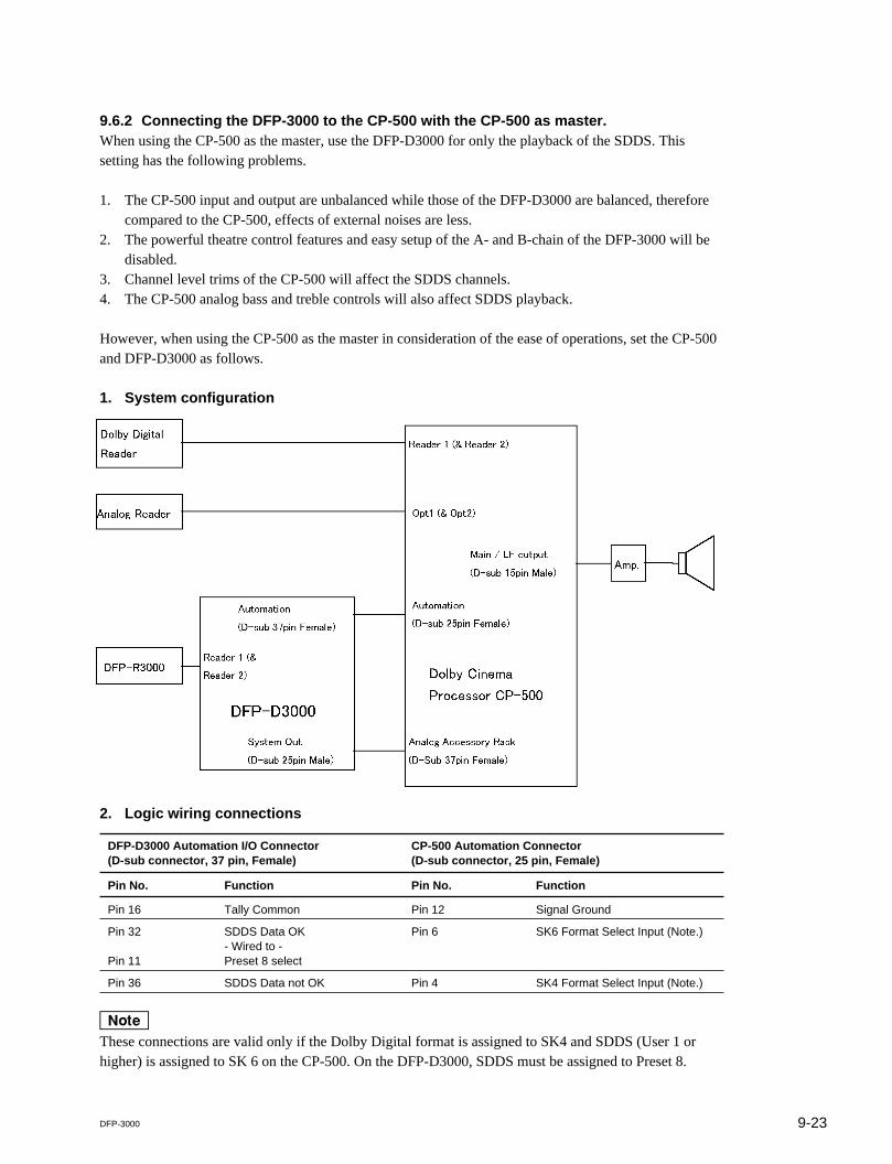
9-23DFP-3000
9.6.2 Connecting the DFP-3000 to the CP-500 with the CP-500 as master.When using the CP-500 as the master, use the DFP-D3000 for only the playback of the SDDS. Thissetting has the following problems.
1. The CP-500 input and output are unbalanced while those of the DFP-D3000 are balanced, thereforecompared to the CP-500, effects of external noises are less.
2. The powerful theatre control features and easy setup of the A- and B-chain of the DFP-3000 will bedisabled.
3. Channel level trims of the CP-500 will affect the SDDS channels.4. The CP-500 analog bass and treble controls will also affect SDDS playback.
However, when using the CP-500 as the master in consideration of the ease of operations, set the CP-500and DFP-D3000 as follows.
1. System configuration
2. Logic wiring connections
DFP-D3000 Automation I/O Connector CP-500 Automation Connector(D-sub connector, 37 pin, Female) (D-sub connector, 25 pin, Female)
Pin No. Function Pin No. Function
Pin 16 Tally Common Pin 12 Signal Ground
Pin 32 SDDS Data OK Pin 6 SK6 Format Select Input (Note.)- Wired to -
Pin 11 Preset 8 select
Pin 36 SDDS Data not OK Pin 4 SK4 Format Select Input (Note.)
nThese connections are valid only if the Dolby Digital format is assigned to SK4 and SDDS (User 1 orhigher) is assigned to SK 6 on the CP-500. On the DFP-D3000, SDDS must be assigned to Preset 8.

9-24 DFP-3000
3. Audio wiring connections
DFP-D3000 System Output connector CP-500 Main/LF output connector(D-sub connector, 25 pin, Male) (D-sub connector, 37 pin, Female)
Pin No. Function Pin No. Function
Pin 1 Left Ground _ No Connection
Pin 2 Left Hot (+) 7 X10 (Left)
Pin 4 Center Ground _ No Connection
Pin 5 Center Hot (+) 6 X11 (Center)
Pin 7 Right Ground _ No Connection
Pin 8 Right Hot (+) 5 X12 (Right)
Pin 9 Left Surround Ground _ No Connection
Pin 10 Left Surround Cold (_) 26 Signal Ground
Pin 11 Right Surround Cold (_) 27 Signal Ground
Pin 12 Subwoofer Cold (_) 28 Signal Ground
Pin 13 Subwoofer Ground _ No Connection
Pin 14 Left Cold (_) 36 Signal Ground
Pin 17 Center Cold (_) 34 Signal Ground
Pin 20 Right Cold (_) 29 Signal Ground
Pin 22 Right Surround Ground _ No Connection
Pin 23 Left Surround Hot (+) 2 X11 (Left Surround)
Pin 24 Right Surround Hot (+) 3 X12 (Right Surround)
Pin 25 Subwoofer Hot (+) 4 X13 (Subwoofer)
nThe outputs of the DFP-3000 are professionally balanced, whereas the inputs of the CP-500 are not.Therefore all DFP-D3000 audio grounds should be connected to shielded wires.
4. Setting up the CP-500On the CP-500, make a custom user format derived from Format 5 (SR). Then change the settings of theCP-500 as follows. (For details, refer to the instruction manual of the CP-500.)
(1) After copying existing format (5), press “Accessory Rack” and select “Xmit/Receive enable”(2) Press “Channel Mute”. Two cross point tables appear.(3) Open all cross points.(4) The first cross point table is called “Accessory rack”. Connect the corresponding channels. (For
example, connect the input Left Channel to the output Left Channel. Set other channels in the sameway.)
(5) The second cross point table (named “Normal”) should be left open.(6) Save the user format as User 1 (or another name) and configure the format selector so that this user
format is assigned to SK6.
With the Automation wiring specified above, if SDDS data is normally detected even once, the DFP-D3000 will send signals to the CP-500 SK6 so that SDDS input sounds are output.The user format set this way is not set as the source of the audio digital function of the CP-500. Thereforeeach time films on more than two digital formats are played back, the SDDS playback is interrupted, andthe SR-D format sound is played back.

9-25DFP-3000
5. Audio input/output level adjustmentsSince the channel output adjustment and output bass and treble adjustments of the CP-500 is done on theoutput board (in the analog domain), these settings will also affect SDDS. Therefore, adjust the B-chainof the CP-500 prior to the B-chain of the DFP-D3000.
To obtain an optimum gain structure, select _10 dBu reference as the DFP-D3000 reference output level,and increase the channel level trims to approximately +2 dB to match the 300 mV reference input level ofthe CP-500.
With this set-up, the master fader of the CP-500 will not affect the playback levels for formats playedthrough the DFP-D3000 and vice versa.
6. DFP-D3000 settingsBasically, as the DFP-D3000 is used only for SDDS reading, use it at the shipment settings. Do not adjustthe DFP-D3000 equalizer and surround delay settings, but set them at the CP-500. It is recommended thatthe DFP-D3000 SDDS Preset (Preset 8) EQ and Surround Delay settings are set to OFF.
7. Using as a changeover systemWhen using the system combining the DFP-D3000 and CP-500 in the changeover format, it is necessaryto supply the motor start pulse and change over command signals for the CP-500 as well. Therefore, addthe following signals to the control signal line and connect the cables.
Projector DFP-D3000 Automation I/O Connector CP-500 Motor Start Connector(D-sub Connector, 37pin, Female) (D-sub Connector, 9pin, Female)
Signal Pin No. Function Pin No. Function
Projector 1 Motor Start Pin 12 Motor 1 Pin 1 Motor Start Projector 1
Projector 2 Motor Start Pin 13 Motor 2 Pin 9 Motor Start Projector 2
Picture Gate Select Pin 19 C/O command, tally Pin 3 Change Over Relay
Common Pin 16 Tally Common Pin 5 GND

9-26 DFP-3000
9.7 Connecting the DTS-6, DTS-6D and DFP-D3000
9.7.1 Outline of System
9.7.2 Requirements of SDDS SideThe DFP-D3000 software version must be more than 2.21. You can check the software version at theStatus screen of the DFP-D3000 menu. For details, refer to the DFP-D3000 operation manual.
9.7.3 Connecting the DTS Processor DTS-6DTS-6 side output: Use the DTS-6 STEREO terminal (15-pin D-sub connector).
m1. No DTS Automation interface board is necessary.2. The DTS output board operation mode in the DTS-6 system must be set to the CP-200 mode. (Set
using two DIP switches. For details, refer to the DTS-6 manual.)
Amp.
DTS Digital
Decoder
DTS-6 / DTS-6D
DFP-D3000
Automation
System Out
AUX1 / AUX2
DFP-R3000
Analog Reader
DTS Reader
Reader
Opt1 / Opt2
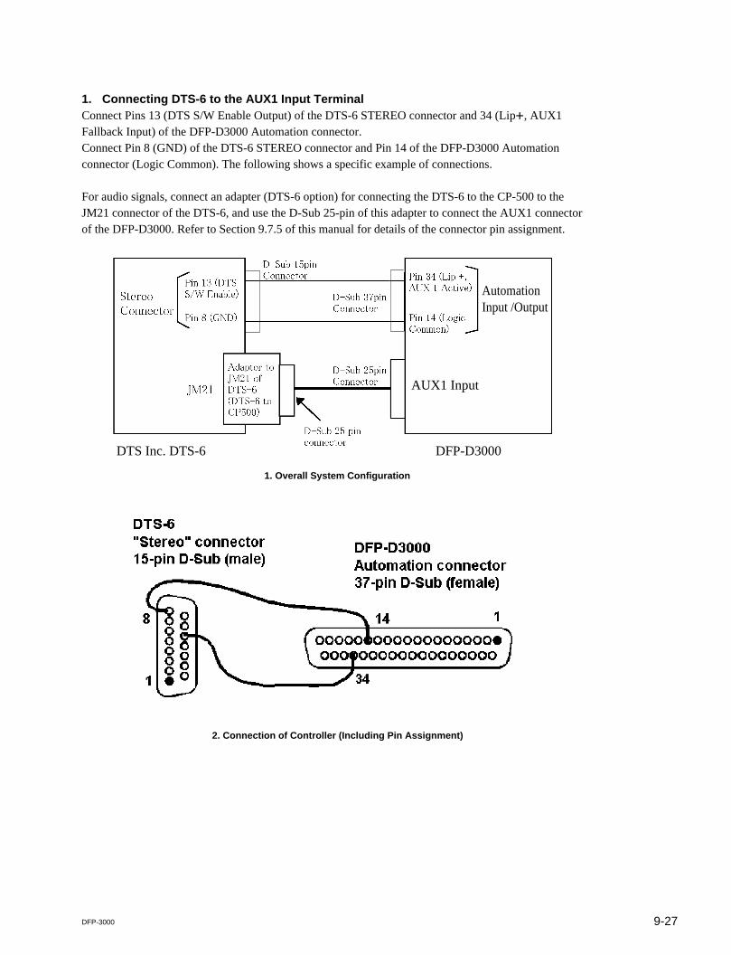
9-27DFP-3000
1. Connecting DTS-6 to the AUX1 Input TerminalConnect Pins 13 (DTS S/W Enable Output) of the DTS-6 STEREO connector and 34 (Lip+, AUX1Fallback Input) of the DFP-D3000 Automation connector.Connect Pin 8 (GND) of the DTS-6 STEREO connector and Pin 14 of the DFP-D3000 Automationconnector (Logic Common). The following shows a specific example of connections.
For audio signals, connect an adapter (DTS-6 option) for connecting the DTS-6 to the CP-500 to theJM21 connector of the DTS-6, and use the D-Sub 25-pin of this adapter to connect the AUX1 connectorof the DFP-D3000. Refer to Section 9.7.5 of this manual for details of the connector pin assignment.
1. Overall System Configuration
2. Connection of Controller (Including Pin Assignment)
AUX1 Input
DTS Inc. DTS-6 DFP-D3000
AutomationInput /Output

9-28 DFP-3000
For this connection, open the Preset Configuration screen of the DFP-D3000 setup software, and set thePrimary Fallback setting to “NR2” in the preset corresponding to the AUX1 input. (Check the enclosedpart of the screen.)
Preset Configuration Screen (When AUX1 is selected)
If fallback must be performed in the order of AUX1 input and Analog input from SDDS, set the PrimaryFallback setting to “AUX1” in the preset corresponding to the SDDS. (Check the enclosed part of thescreen.)
Preset Configuration Screen (When SDDS is selected)
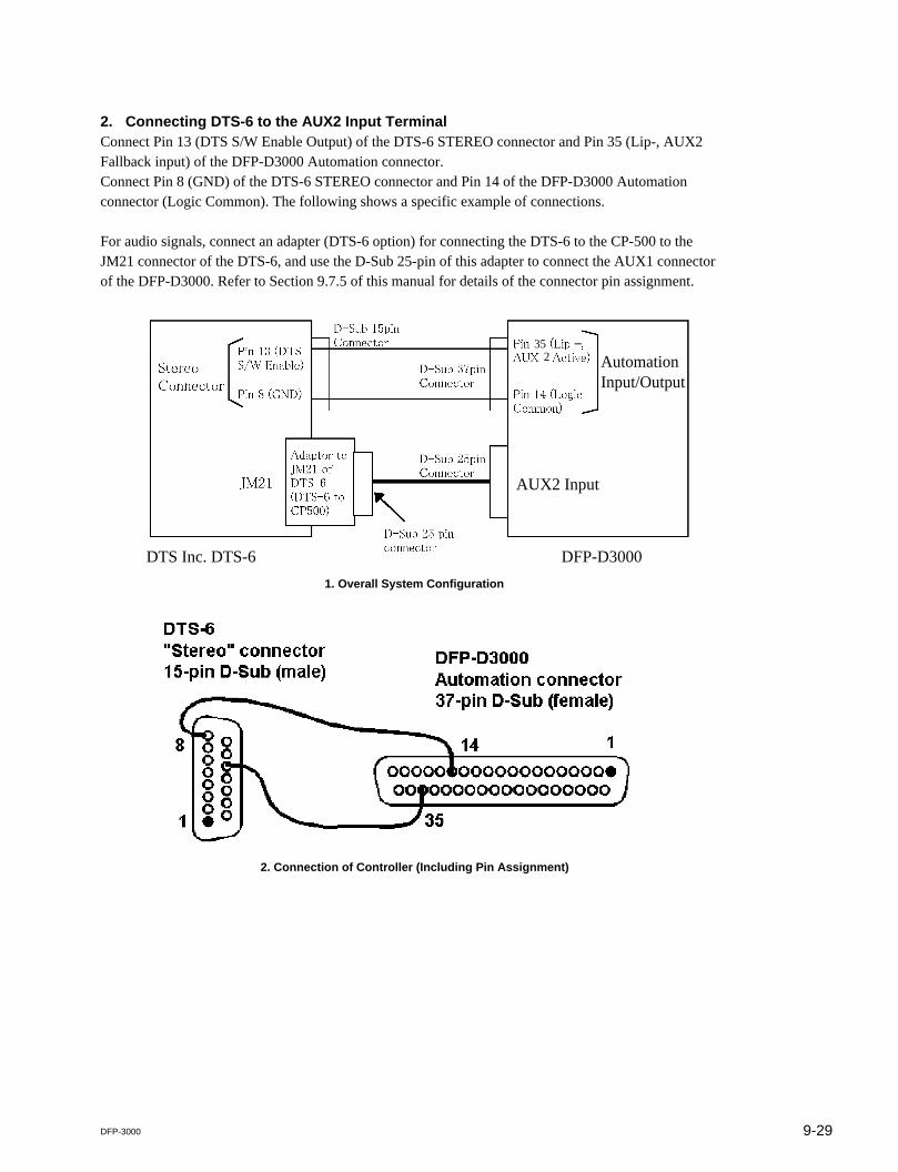
9-29DFP-3000
2. Connecting DTS-6 to the AUX2 Input TerminalConnect Pin 13 (DTS S/W Enable Output) of the DTS-6 STEREO connector and Pin 35 (Lip-, AUX2Fallback input) of the DFP-D3000 Automation connector.Connect Pin 8 (GND) of the DTS-6 STEREO connector and Pin 14 of the DFP-D3000 Automationconnector (Logic Common). The following shows a specific example of connections.
For audio signals, connect an adapter (DTS-6 option) for connecting the DTS-6 to the CP-500 to theJM21 connector of the DTS-6, and use the D-Sub 25-pin of this adapter to connect the AUX1 connectorof the DFP-D3000. Refer to Section 9.7.5 of this manual for details of the connector pin assignment.
1. Overall System Configuration
2. Connection of Controller (Including Pin Assignment)
352
_
Automation Input/Output
AUX2 Input
DTS Inc. DTS-6 DFP-D3000
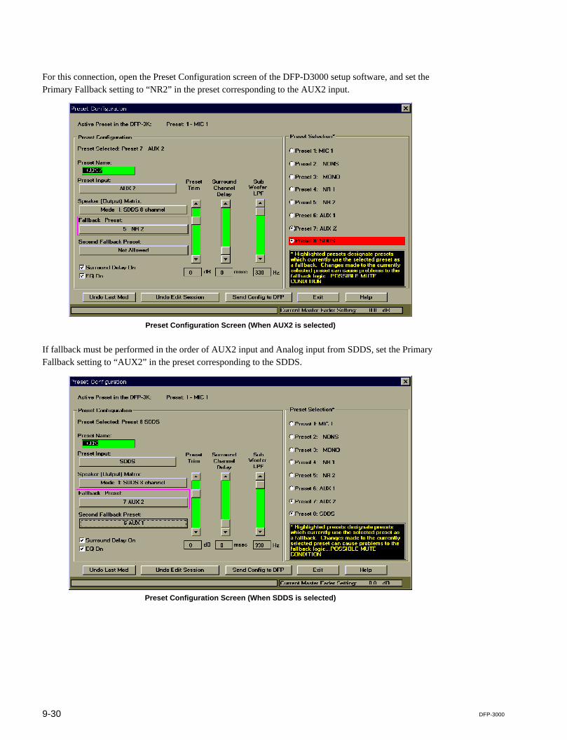
9-30 DFP-3000
For this connection, open the Preset Configuration screen of the DFP-D3000 setup software, and set thePrimary Fallback setting to “NR2” in the preset corresponding to the AUX2 input.
Preset Configuration Screen (When AUX2 is selected)
If fallback must be performed in the order of AUX2 input and Analog input from SDDS, set the PrimaryFallback setting to “AUX2” in the preset corresponding to the SDDS.
Preset Configuration Screen (When SDDS is selected)

9-31DFP-3000
9.7.4 Connection of Control Signals from DTS Processor DTS-6DDTS6D side output: Use the DTS-6D Automation terminal (25-pin D-sub connector).
There is no need to use the DTS Automation interface board.
The following shows an example of system control system connections.

9-32 DFP-3000
1. Connecting the DTS-6D to the AUX1 input terminalConnection when using the AUX1 terminalConnect Pin 10 (GND when Digital output) of the DTS-6D Automation connector and Pin 34 (Lip+,AUX1 Fallback input) of the DFP-D3000 Automation connector.Connect Pin 13 (GND) of the DTS-6 Automation terminal and Pin 14 of the DFP-D3000 Automationconnector (Logic Common). The following shows a specific example of connections.
For audio signals, use a DTS-6D analog output connector (D-sub, 25 pin) to connect the AUX1 of theDFP-D3000. Refer to Section 9.7.5 of this manual for details of the connector pin assignment.
nWhen connecting the DTS-6D to the DFP-D3000, the DTS Automation Interface board is not necessary.
1. Overall System Configuration
2. Connection of Controller
Pin 10 (GND when Digital)
Pin 13 (GND)
Pin 34 (Lip +, AUX1 Active)
Pin 14 (Logic Common)
Automation Connector
Analog Output Connector
Automation Input /Output
AUX1 Input
D-sub 25 pinConnector
D-sub 25 pinConnector
D-sub 25 pinConnector
D-sub 37 pinConnector
DTS Inc. DTS-6D DFP-D3000
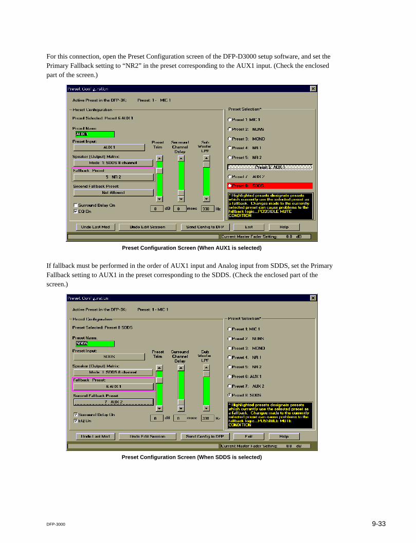
9-33DFP-3000
For this connection, open the Preset Configuration screen of the DFP-D3000 setup software, and set thePrimary Fallback setting to “NR2” in the preset corresponding to the AUX1 input. (Check the enclosedpart of the screen.)
Preset Configuration Screen (When AUX1 is selected)
If fallback must be performed in the order of AUX1 input and Analog input from SDDS, set the PrimaryFallback setting to AUX1 in the preset corresponding to the SDDS. (Check the enclosed part of thescreen.)
Preset Configuration Screen (When SDDS is selected)
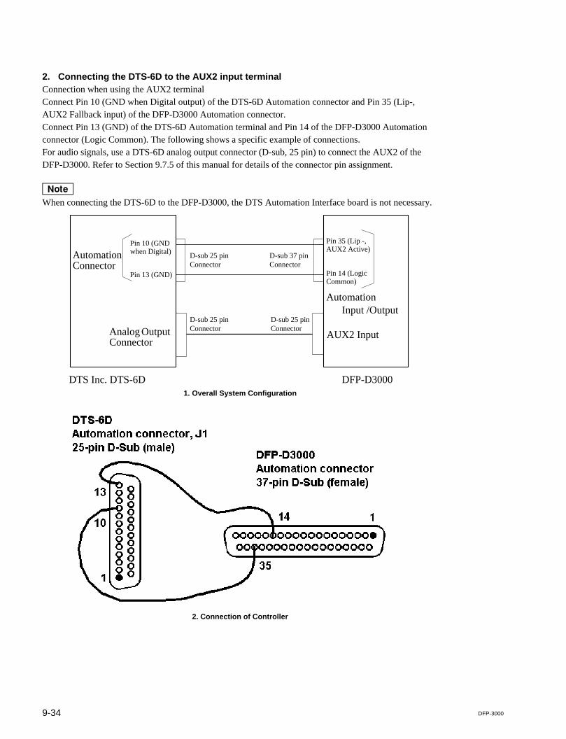
9-34 DFP-3000
2. Connecting the DTS-6D to the AUX2 input terminalConnection when using the AUX2 terminalConnect Pin 10 (GND when Digital output) of the DTS-6D Automation connector and Pin 35 (Lip-,AUX2 Fallback input) of the DFP-D3000 Automation connector.Connect Pin 13 (GND) of the DTS-6D Automation terminal and Pin 14 of the DFP-D3000 Automationconnector (Logic Common). The following shows a specific example of connections.For audio signals, use a DTS-6D analog output connector (D-sub, 25 pin) to connect the AUX2 of theDFP-D3000. Refer to Section 9.7.5 of this manual for details of the connector pin assignment.
nWhen connecting the DTS-6D to the DFP-D3000, the DTS Automation Interface board is not necessary.
1. Overall System Configuration
2. Connection of Controller
Pin 10 (GND when Digital)
Pin 13 (GND)
Pin 35 (Lip -, AUX2 Active)
Pin 14 (Logic Common)
Automation Connector
Analog Output Connector
Automation Input /Output
AUX2 Input
D-sub 25 pinConnector
D-sub 25 pinConnector
D-sub 25 pinConnector
D-sub 37 pinConnector
DTS Inc. DTS-6D DFP-D3000
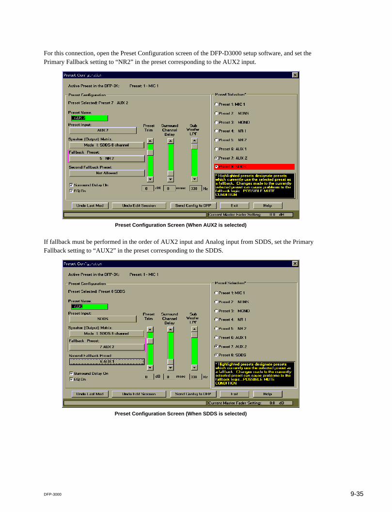
9-35DFP-3000
For this connection, open the Preset Configuration screen of the DFP-D3000 setup software, and set thePrimary Fallback setting to “NR2” in the preset corresponding to the AUX2 input.
Preset Configuration Screen (When AUX2 is selected)
If fallback must be performed in the order of AUX2 input and Analog input from SDDS, set the PrimaryFallback setting to “AUX2” in the preset corresponding to the SDDS.
Preset Configuration Screen (When SDDS is selected)

9-36 DFP-3000
9.7.5 Audio Connecting the DTS-6, DTS-6D and DFP-D3000For details of the connection, refer to the following table.
DFP-D3000 AUX Input 1/2 DTS-6 Adaptor to JM21 DTS-6D Analog out(DB25, F/Cable M) “TS6 to CP500” (DB25 M/Cable F)
1 Left Ground N.C. N.C.
2 Left Hot 14 Left 14 Left
3 Left Center Cold N.A. N.A.
4 Center Ground N.C. N.C.
5 Center Hot 20 Center 20 Center
6 Right Center Cold N.A. N.A.
7 Right Ground N.C. N.C.
8 Right Hot 17 Right 17 Right
9 Left Surround Ground N.C. N.C.
10 Left Surround Cold 4 Audio Return 4 Audio Return
11 Right Surround Cold 3 Audio Return 3 Audio Return
12 Sub Woofer Cold 12 Audio Return 12 Audio Return
13 Sub Woofer Ground N.C. N.C.
14 Left Cold 1 Audio Return 1 Audio Return
15 Left Center Ground N.A. N.A.
16 Left Center Hot N.A. N.A.
17 Center Cold 8 Audio Return 8 Audio Return
18 Right Center Ground N.A. N.A.
19 Right Center Hot N.A. N.A.
20 Right Cold 5 Audio Return 5 Audio Return
21 N.C. N.C. N.C.
22 Right Surround Ground N.C. N.C.
23 Left Surround Hot 15 Left Surround Out 15 Left Surround Out
24 Right Surround Hot 2 Right Surround Out 2 Right Surround Out
25 Sub Woofer Hot 24 Sub Woofer Out 24 Sub Woofer Out
N.A.: No corresponding function. N.C.: Not connected.
m1. All audio grounds must be connected to the shield side of each twisted pair cables at the DFP-D3000.2. The DTS-6 audio outputs must be connected using the “DTS6 to CP500 adaptor” provided by the
DTS dealer.

9-37DFP-3000
9.8 Corresponding to DFP-D3000 Surround EX
9.8.1 Restrictions on Control of Surround EX Decoder1. For Surround EX, information for expressing “Surround EX” on film in any digital format is not
written. For this reason, when controlling the Surround EX processor, there is a need to control theSurround EX decoder from the DFP-D3000 only when processing the Surround EX decoding for theSDDS signal.
2. When performing Surround EX decoding for other digital formats, accurate control from the DFP-D3000 is not possible. In this case, use the control signal from each equipment. Due to effects of thefallback operation on the DFP-D3000, operations may not be smooth in some cases.
3. The DFP-D3000 software must be changed to a version above V2.61. If B-chain settings havealready been completed, change the setup software version for the DFP-D3000 to V2.00 build 2.044or above, and read out the set data before upgrading the version. After upgrading the version, re-sendthe read out data to the unit.For DFP-D3000 models shipped after September 1999, use the software provided at shipment.
9.8.2 Connections of Audio SystemConnect the audio system as follows.
Of the DFP-D3000 audio outputs, connect the Surround Left output and Surround Right output to the SA-10 Surround input. To connect the Surround outputs of the SA-10, connect the four outputs from the SA-10 (Surround Left, Surround Back-Left, Surround Back-Right, Surround Right) to the speaker via thepower amplifier according to the SA-10 manual. In this case, use the switching circuit in the SA-10 toturn ON and OFF the Surround EX mode to switch the sounds.
The following restrictions apply in the combination with the V2.61 software.
. At the DFP-D3000 side, as the EQ setting cannot be changed for every preset, if combining with theSurround EX processor, adjust the level and equalizer of the surround channel at the Surround EXprocessor side.(In other words, for the surround channels, adjust the B-chain using the Surround EX processor.)Therefore at the DFP-D3000, turn OFF the equalizer of the surround channel, and at the same time,adjust the offset of the surround channel level so that the output level of the surround channel becomes_16 dBu. When adjusting the sound level, set the amplitude to a high level at the power amplifier.
. For channels other than the surround channel, adjust the equalizer at the DFP-D3000 side.

9-38 DFP-3000
Example of Audio System Connection
L : Left Channel LC : Left Center Channel C : Center ChannelRC : Right Center Channel R : Right Channel SW : Sub Woofer ChannelLS : Left Surround Channel RS : Right Surround Channel BS : Back Surround Channel
During normal operations: The same sounds are output from the LS channel speaker and BS (L) channelspeaker. The same sounds will also be output from the RS channel speakerand BS (R) channel speaker.
During Surround EX: The same sounds are output from the BS (L) channel speaker and BS (R)channel speaker. Different sounds will also be output from the LS channelspeaker and RS channel speaker. (In other words, there are three surroundchannels: LS, BS, and RS.)
Surround EXDecoderSA-10
SDDS DecoderDFP-D3000
CinemaSoundEquipment
CinemaSoundEquipment

9-39DFP-3000
9.8.3 Actual Connection of Control SystemWhen controlling operations of the Dolby Laboratories SA-10 (Surround EX processor) from the DFP-D3000 (switch the Surround EX mode between ON and OFF), connect the control input connector on therear panel of the SA-10 and Automation connector on the DFP-D3000 as follows.
1. Settings at the SA-10 (Surround EX Processor) side. Set the control mode switch SW1 (located on the daughter board) in the SA-10 to the “CP65” position.. Push in (Normal position) the “Alignment Switch S602” on the rear of the SA-10 front panel.. Set the “Surround switch” on the SA-10 front panel to the “Enable” position.
2. Connections of the Control Cable Between the DFP-D3000 and SA-10. Connect Pin 14 (Logic Common) of the DFP-D3000 Automation connector to Pin 12 (GND) of the
Control Input connector of SA-10.. Connect Pin 32 (SDDS OK) of the DFP-D3000 Automation connector to Pin 4 (CTRL 4, EX decode
mode) of the Control Input connector of SA-10.. Connect Pin 36 (ACM) of the DFP-D3000 Automation connector to Pin 2 (CTRL1, non decode mode)
of the Control Input connector of SA-10.
With this connection, the signal for indicating the read state of the SDDS is sent to the SA-10 controlsignal input which is the Surround EX Processor, and the SA-10 operations are controlled via the controlcable according to the SDDS signal state.
9-40 DFP-3000
9.8.4 SA-10 Operations When Controlling from the DFP-D3000The system combining the DFP-D3000 and SA-10 performs the following operations at the settings andconnections described until now.
1. When the SDDS film is played backThe following operations are performed when the SDDS film is played back.
When the SDDS film is identified by the DFP-D3000, the SDDS OK pulse is output from Pin 32 of theAutomation connector. As a result of sending the pulse to the SA-10 control input, the “Surround EXMode” LED lights up on the Surround EX Processor SA-10, and the Surround EX decode function turnsON (EX mode).
If there are large scratches on the SDDS film, or if film with no SDDS signal arrives and SDDS signalcannot be read, the ACM pulse is output from the Pin 36 of the Automation connector. As a result, the“Surround EX Mode” LED lights up on the Surround EX Processor SA-10, and the Surround EX decodefunction goes OFF (normal mode).
2. When other format film is played backIn this case, even if the Surround Mode switch on the SA-10 front panel is set to the “Surround EXEnable” mode, the “Surround EX Mode” LED lights up on the Surround EX Processor SA-10, and theSurround EX decode function goes OFF (normal mode).
nEven other format sounds (Dolby Digital, DTS, Dolby SR) are played without selecting the SDDS soundin the use of films recorded with SDDS, Surround EX control will be performed using the read state ofthe SDDS data. This must be borne in mind carefully.

9-41DFP-3000
9.8.5 Controlling Surround EX from DA-20When combining the Dolby Digital format decoder Dolby Laboratories DA-20 and DFP-D3000, theSDDS decoder DFP-D3000 should be used instead of the CP-65 and CP-55 Dolby Laboratories Cinemasound processors. For the DFP-D3000, as Dolby Digital format conditions are detected using the levelsignal (method of determining the OK/NG state of the digital format according to the High/Low state ofthe terminal voltage) as done in the Dolby Laboratories cinema sound processor CP-200, operations willbe different from the current Dolby Laboratories cinema processor (adopts pulse signal input).
To control surround EX from the DA-20, use the following method.
1. Since the DFP-D300 is designed so that the designated operations are performed when it receives theDolby Laboratories CP-200 control signal (voltage level output method), set the DA-20 operations inthe same way as when CP-200 is used. For reference, a diagram showing the connection of the DFP-D3000 and DA-20 is shown on the next page.
2. Distribute the signal sent from the DA-20 from the DFP-D3000 Automation connector, convert thesignal to a pulse signal, and send to the SA-10 control signal input. In this case, use the signalconversion adapter Cat. 845 available from Dolby. Connect this adapter to the SA-10 Control Inputterminal (J3). Specifically, connect DA-20 and DFP-D3000.
DA-20, Sense/Control DFP-D3000 Automation Cat. 845(J6, 25-pin D-sub) (37-pin D-sub) (to SA-10, J3 Control Input)
Pin 1, CTRL0 Output Pin 34: AUX1 digital data OK or Red Wire (for Pin 1)Pin 35: Aux2 digital data OK
Note that with the Cat. 845 adapter, true level signals are not converted to pulse signals (level signalcomponents are continuously output). As a consequence, SA-10 cannot be controlled simultaneouslyfrom all digital formats. To control SA-10 from other formats, stop the Cat. 845 operations. For details onthe Cat. 845, contact Dolby Laboratories or a Dolby Laboratories Dealer.
At such settings, when Dolby Digital format signals are read correctly, the Surround EX decoder willoperate and Surround EX decoding is performed. If the Dolby Digital format signals are not read correct-ly, Surround EX decoding will not be performed. In this case, when preset is selected but the Presetcorresponding to the Dolby Digital format signal is not selected correctly, Surround EX decoding may beperformed where not needed.
To control SA-10 from the DFP-D3000, third party solutions are available from a variety of outsidevendors and suppliers of cinema equipment, such as Smart Devices Inc (USA), Hasso GmbH (Germany)and others. Contact the vendors directly for the latest information about their available products.

9-42 DFP-3000
1. Connecting DA-20 to the AUX1 input terminal
2. Connecting DA-20 to the AUX2 input terminal
Pin 1 (Ctri 0)
Pin 14 (Senced)
Pin 12 (GND)
Pin 34 (Lip +.AUX1 Active)
Pin 14 (Logic Common)
Automation Input /Output
AUX1 Input
D-sub 25 pinConnector
D-sub 37 pinConnector
D-sub 25 pinConnector
D-sub 25 pinConnector
Dolby Laboratories, Inc. DA-20 DFP-D3000
CP AudioConnector (J8)
Sence / Contorl (J6)
Pin 1 (Ctri 0)
Pin 14 (Senced)
Pin 12 (GND)
Pin 35 (Lip +.AUX1 Active)
Pin 14 (Logic Common)
Automation Input /Output
AUX2 Input
D-sub 25 pinConnector
D-sub 37 pinConnector
D-sub 25 pinConnector
D-sub 25 pinConnector
Dolby Laboratories, Inc. DA-20 DFP-D3000
CP AudioConnector (J8)
Sence / Contorl (J6)

9-43DFP-3000
9.8.6 Controlling Surround EX from DTS-6 or DTS-6DWhen using the DTS Co. DTS-6 or DTS-6D in the DFP-D3000 system, SA-10 operations can be con-trolled from these cinema processors (DTS decoder) in the DFP-D3000 system.
In this case, connect the control cables of the DTS-6 or DTS-6D and SA-10 as follows. In this case, theSA-10 can be controlled regardless of the DFP-D3000 control cables.
DTS-6 “to BS22” connector DTS-6D Automation connector SA-10 J3, Control Input(IDC 10-pin Connector) (DB25 female) (DB25 female)
Pin 6: Relay Common Pin 13: Output common Pin 12: GND
Pin 9: out (N.O.) Pin 11: Logic SR Pin 2: CTRL 1, non-decode Mode
Pin 7: IN (N.O) Pin 25: Logic DTS Pin 5: CTRL 4, EX decode mode
The following cables are required other than the above for the DTS-6D system.Connect Pin 6 “Force SR +” and Pin 9 “+5V Output” of the Automation connector.Connect Pin 19 “Force SR _” and Pin 22 “5V GND” of the Automation connector.
9.8.7 Controlling Surround EX control from Automation ControllerWhen fallback using several digital formats is adopted in the DFP-D3000 system, or the SDDS signalcannot be read, it is necessary to cancel the SA-10 Surround EX decoding operations as soon as possible.It is also necessary to ensure compatibility for films not recorded with the Surround EX signal. Bychanging the preset settings of the DFP-D3000, and preparing preset using the Surround EX not corre-sponding to the SDDS input and preset not using the Surround EX (same as the Dolby Laboratories CP-500), Surround EX can be controlled from an external Automation controller. The examples of presetsettings and connection methods of control cables are shown on the next page onwards. However whenusing this connection method, set the Processor Select switch in the SA-10 to the CP-500 side.
DFP-D3000 Preset DFP-D3000 Automation SA-10, J3 Control Input(37 pin, D-Sub, Female) (25 pin, D-sub, Female)
Preset 1: SDDS Pin 4: Preset 1 Pin 2: CTRL 1
Preset 2: Non-Sync Pin 5: Preset 2 Pin 3: CTRL 2
Preset 3: Mono (Pin 6: Ptrdry 3) No need No need to connect
Preset 4: NR1 Pin 7: Preset 4 Pin 4: CTRL 3
Preset 5: NR2 Pin 8: Preset 5 Pin 5: CTRL 4
Preset 6: AUX 1 Pin 9: Preset 6 Pin 6: CTRL 5
Preset 7: AUX 2 Pin 10: Preset 7 Pin 7: CTRL 6
Preset 8: SDDS EX Pin 11: Preset 8 Pin 8: CTRL 7
Pin 16: Tally Common Pin 12: GND

9-44 DFP-3000
9.8.8 Adjustments of Audio SystemDetails of the connections and adjustments of the audio system are provided in “Connections of the AudioSystem”. Below, the adjustment methods are described.
Of the DFP-D3000 audio output, the Surround Left output and Surround Right output will be connectedto the Surround input of the SA-10. Currently, as the EQ setting cannot be changed for each preset in theDFP-D3000, when combining it with the Surround EX processor, adjust the level with the equalizer ofthe surround channel at the Surround EX processor side. In other words, perform B-chain adjustmentsusing the Surround EX processor for the surround channels.
For the Surround EX processor, if the level of signals input to the surround processor is not adjustedproperly, the designated surround effects cannot be obtained. For this reason, there is a need to adjust thelevel of signals sent to the Surround EX processor from the SDDS.
The following describes the procedures for setting the level of the signal output from the DFP-D3000 tothe Surround EX processor, and the equalizer.
Equipment required. Personal computer installing the DFP-D3000 setup software. Interlink cables (cross cables and all pins must be cross connected). Audio level meter (or AC voltmeter)
Adjusting/setting procedures and measurements1. Connect the DFP-D3000 and personal computer using interlink cables. When using a commercially
available interlink cable, as male D-Sub 9 pin connectors are provided at the two ends of the cable, itis necessary to change only the DFP-D3000 side to the female connector. In this case, use a commer-cially available polarity converter connector (gender changer) to convert the connector shape. As theDFP-D300 uses mm screws (ISO standard) for fixing the connector (side secured by the screws),when using cables for the PC, the adjustment/setting/measurement can be done more easier if thefixing screws at the connecting side of the cable to the PC is removed.
2. Turn on the power of the DFP-D3000 and Surround EX processor. Turn the power of the poweramplifier until level adjustments complete.

9-45DFP-3000
3. Start the DFP-D3000 setup software on the PC. When started, the screen shown in Fig. 1 will bedisplayed. Click “Connect to DFP” from the Config menu to start communication with the DFP-D3000. At this time, the serial number information of the unit will be required. The serial number ofthe unit is indicated at the name plate on the right side of the unit. If the setup software has not yetbeen started, the serial number can also be viewed on the LCD screen of he DFP-D3000. (For detailson operations, refer to the menu tree in the operation manual.)
Fig. 1. Initial State of Setup Screen
4. Select “Master DFP-D3000” from the “Master” menu at the screen shown in Fig. 1. The screenshown in Fig. 2 will be displayed.
Fig.2. DFP-D3000 Output Reference Level Setting Screen
Setting to thisSetting to this
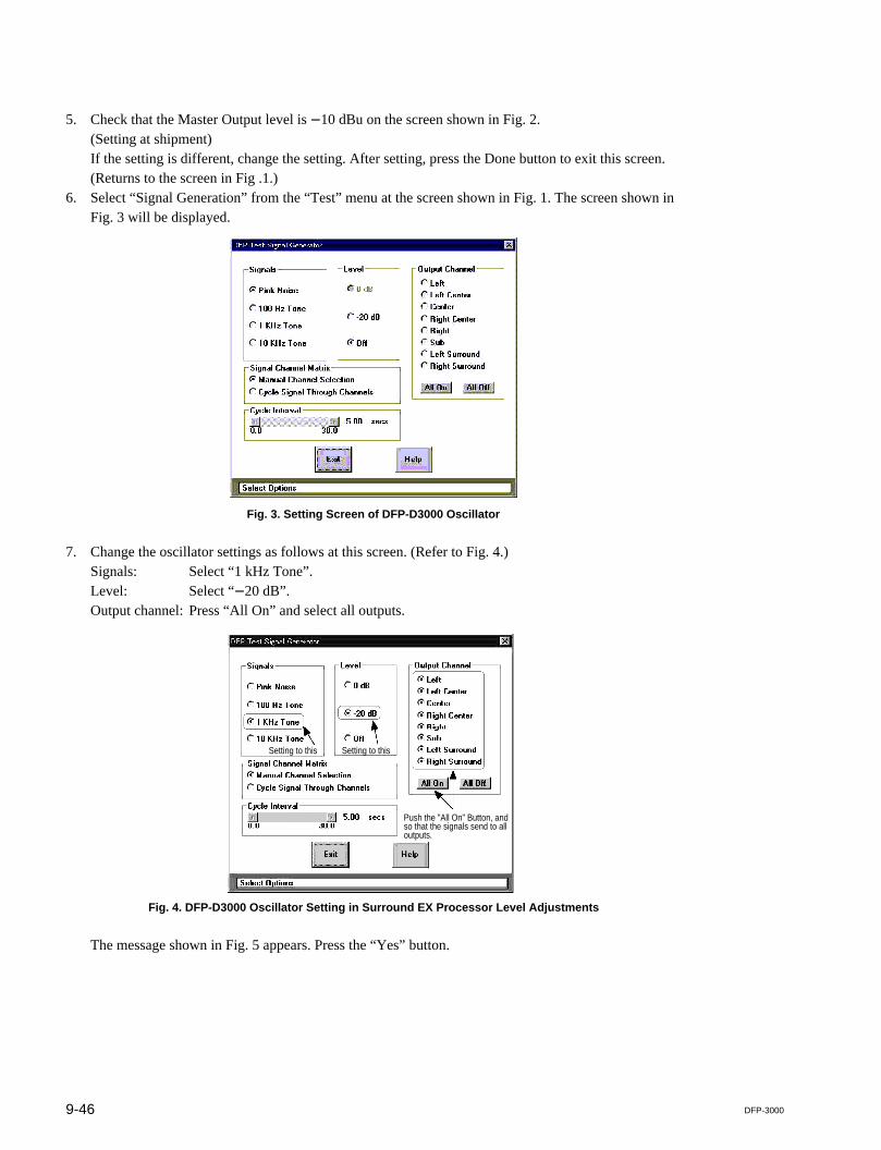
9-46 DFP-3000
5. Check that the Master Output level is _10 dBu on the screen shown in Fig. 2.(Setting at shipment)If the setting is different, change the setting. After setting, press the Done button to exit this screen.(Returns to the screen in Fig .1.)
6. Select “Signal Generation” from the “Test” menu at the screen shown in Fig. 1. The screen shown inFig. 3 will be displayed.
Fig. 3. Setting Screen of DFP-D3000 Oscillator
7. Change the oscillator settings as follows at this screen. (Refer to Fig. 4.)Signals: Select “1 kHz Tone”.Level: Select “_20 dB”.Output channel: Press “All On” and select all outputs.
Fig. 4. DFP-D3000 Oscillator Setting in Surround EX Processor Level Adjustments
The message shown in Fig. 5 appears. Press the “Yes” button.
Push the "All On" Button, andso that the signals send to alloutputs.
Setting to this Setting to this
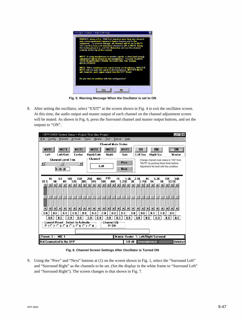
9-47DFP-3000
Fig. 5. Warning Message When the Oscillator is set to ON
8. After setting the oscillator, select “EXIT” at the screen shown in Fig. 4 to exit the oscillator screen.At this time, the audio output and master output of each channel on the channel adjustment screenwill be muted. As shown in Fig. 6, press the Surround channel and master output buttons, and set theoutputs to “ON”.
Fig. 6. Channel Screen Settings After Oscillator is Turned ON
9. Using the “Prev” and “Next” buttons at (1) on the screen shown in Fig. 1, select the “Surround Left”and “Surround Right” as the channels to be set. (Set the display in the white frame to “Surround Left”and “Surround Right”). The screen changes to that shown in Fig. 7.
Change channel mute status to "ON" from"MUTE" by pushing these three buttonsAdjustment the level with this condition.
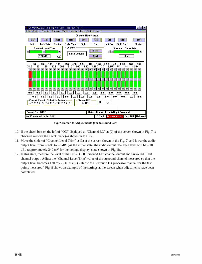
9-48 DFP-3000
Fig. 7. Screen for Adjustments (For Surround Left)
10. If the check box on the left of “ON” displayed at “Channel EQ” at (2) of the screen shown in Fig. 7 ischecked, remove the check mark (as shown in Fig. 9).
11. Move the slider of “Channel Level Trim” at (3) at the screen shown in the Fig. 7, and lower the audiooutput level from _3 dB to _6 dB. (At the initial state, the audio output reference level will be _10dBu (approximately 240 mV for the voltage display, state shown in Fig. 8).
12. In this state, measure the level of the DFP-D300 Surround Left channel output and Surround Rightchannel output. Adjust the “Channel Level Trim” value of the surround channel measured so that theoutput level becomes 120 mV (_16 dBu). (Refer to the Surround EX processor manual for the testpoints measured.) Fig. 8 shows an example of the settings at the screen when adjustments have beencompleted.
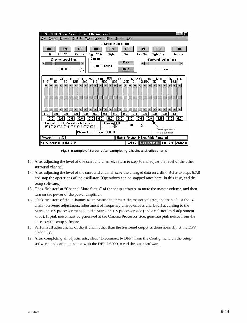
9-49DFP-3000
Fig. 8. Example of Screen After Completing Checks and Adjustments
13. After adjusting the level of one surround channel, return to step 9, and adjust the level of the othersurround channel.
14. After adjusting the level of the surround channel, save the changed data on a disk. Refer to steps 6,7,8and stop the operations of the oscillator. (Operations can be stopped once here. In this case, end thesetup software.)
15. Click “Master” at “Channel Mute Status” of the setup software to mute the master volume, and thenturn on the power of the power amplifier.
16. Click “Master” of the “Channel Mute Status” to unmute the master volume, and then adjust the B-chain (surround adjustment: adjustment of frequency characteristics and level) according to theSurround EX processor manual at the Surround EX processor side (and amplifier level adjustmentknob). If pink noise must be generated at the Cinema Processor side, generate pink noises from theDFP-D3000 setup software.
17. Perform all adjustments of the B-chain other than the Surround output as done normally at the DFP-D3000 side.
18. After completing all adjustments, click “Disconnect to DFP” from the Config menu on the setupsoftware, end communication with the DFP-D3000 to end the setup software.
Do not operate asfor the equalizer.

9-50 DFP-3000
nIt is also possible to play film recorded with Dolby tone instead of the built-in oscillator to adjust theoutput level of the DFP-D3000. If SDDS format film with such tones are not available, use a DolbyDigital format or analog film and switch the preset according to the film used.
In this case, open the “Preset Configuration” in the “Preset” menu, set the “Offset Trim” setting of thepreset number corresponding to the format of the film played back to 0 dB before performing the actualadjustments.
When performing adjustments, also switch the preset setting according to the corresponding film formatat “Current Preset-Select to Activate” at the bottom left of the channel adjustment screen.
As of December 1999, there is no film for adjustment recorded with Dolby tones in the SDDS format.Therefore use the Dolby Digital format or analog format level film or use the built-in oscillator of theDFP-D3000.
One of the reasons for why this manual recommends the use of the built-in oscillator is because; effects ofthe offset trim setting at each preset may be received during adjustments when the Surround EX processoris added to the existing equipment.(When the offset trim is set, there may be a difference between the reference level (_20 dB) in the unitand the level of the signal from the film used for adjusting the signal level). When the built-in oscillator isused, the effects of the offset trim setting are not received.
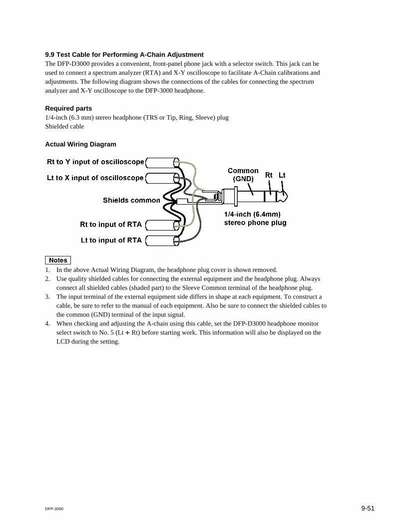
9-51DFP-3000
9.9 Test Cable for Performing A-Chain AdjustmentThe DFP-D3000 provides a convenient, front-panel phone jack with a selector switch. This jack can beused to connect a spectrum analyzer (RTA) and X-Y oscilloscope to facilitate A-Chain calibrations andadjustments. The following diagram shows the connections of the cables for connecting the spectrumanalyzer and X-Y oscilloscope to the DFP-3000 headphone.
Required parts1/4-inch (6.3 mm) stereo headphone (TRS or Tip, Ring, Sleeve) plugShielded cable
Actual Wiring Diagram
m1. In the above Actual Wiring Diagram, the headphone plug cover is shown removed.2. Use quality shielded cables for connecting the external equipment and the headphone plug. Always
connect all shielded cables (shaded part) to the Sleeve Common terminal of the headphone plug.3. The input terminal of the external equipment side differs in shape at each equipment. To construct a
cable, be sure to refer to the manual of each equipment. Also be sure to connect the shielded cables tothe common (GND) terminal of the input signal.
4. When checking and adjusting the A-chain using this cable, set the DFP-D3000 headphone monitorselect switch to No. 5 (Lt + Rt) before starting work. This information will also be displayed on theLCD during the setting.
9-52 DFP-3000
9.10 Adjusting the Analog Track PickupDigital audio tracks set a very high standard of quality for theatrical sound playback. In order to minimizethe difference between sound from digital tracks and sound reproduced from a film’s optical tracks, theproper skills as well as caution are required for ensuring the best performance of the optical reader. Thischapter mainly describes the forward scan reader. As reverse scan readers have related adjustments whichmay be slightly different for each brand, contact the appropriate manufacturer for specific instructions.When adjusting the optical reader, follow the adjustment method indicated in the manual of the readerused.
When adjusting A-Chain inputs, it is not necessary to provide commands to the Automation system of theprojector if the exciter lamp of the analog surround track is lit. (Only when the exciter lamp is off mustthe Automation system be operated to light the exciter lamp.) The exciter lamp voltage should normallybe set to 75-85 % of its rated voltage as recommended by the manufacturer. As the following adjustmentstypically interact with each other, they must be rechecked after initial settings.
9.10.1 Preliminary Preparations Before AdjustmentsFirst thoroughly clean the sound head optics. Replace the exciter lamp if it is discolored or if it is notsufficiently bright across the width of the slit and when its light falls on a white card held about an inch infront of the optics. Be sure that the solar cell is mounted 1 mm away from the film. The most commoncauses of uneven illumination are misaligned optics, dirty or aged exciter lamp, dirty optics or slit, andrunning of the exciter lamp at a voltage that is too low.
9.10. 2 Lateral Film Guide AdjustmentThe next step in adjusting the projector’s optical reader is to ensure that the optical pickup is correctlyadjusted to the optical tracks on the film. This is done by playing a loop of the SMPTE Buzz Track testfilm and adjusting the projector’s lateral film guide for equal and minimum high and low frequency soundfrom the left and right outputs. If you are adjusting an overscanning reverse scan reader you can alsoperform this adjustment using the X-Y oscilloscope by equalizing the perpendicular X and Y traces.
9.10.3 Lateral Exciter Lamp AdjustmentNext in setting up a forward scan reader, roll a Cat. 97 “left/right” or “crosstalk” loop and observe thesignal when the film is run using a dual trace oscilloscope. Adjust the lateral position of the exciter lampto equalize the left and right output signal levels. Generally this adjustment can be facilitated by setting sothat the two channels overlap on the oscilloscope.
9.10.4 Lateral Solar Cell AdjustmentWhile playing the left/right loop, adjust the lateral position of the solar cell so as to achieve minimalcrosstalk between left and right output outputs. Generally, this adjustment can be facilitated by setting sothat two input states can be observed separately on the oscilloscope.

9-53DFP-3000
9.10.5 Vertical Adjustment of Exciter LampFor forward scan readers, set the oscilloscope to the X-Y display mode, and connect the same signals tothe RTA (real time analyzer, spectrum analyzer). Play a loop film recorded with (black-and-white) pinknoise signal, and adjust the output level from the analog pickup to the point where the highest frequencycharacteristics become. If necessary, adjust to the preferred frequency characteristics.
9.10.6 Slit Lens AdjustmentAdjust the focus of the slit lens of the pickup where the frequency characteristics of the pink noisebecomes the flattest. Rotate the slit lens so that the phase difference becomes minimum on the X-Yoscilloscope, and adjust the azimuth of the slit.
9.10.7 Double Checking of Illumination InconsistencyEven illumination from the slits is essential to reducing high level distortion and in the decoding ofsurround signals from the Lt/Rt. Falloff at the outside edges will result in high frequency loss and play-back that sounds muffled. Assuring proper playback of high levels is especially important, as modernanalog track cameras can readily print stereo tracks at 130 % modulation without loss of the septum, andthis extra range is commonly utilized.To check for proper illumination, play a 100 % modulation alignment film, such as the Cat. 97 left/rightfilm, and also a 50 % or 60 % modulation alignment film, such as the Cat. 69T. The levels of the leftsignal and right signal should be equal to each other when playing either film. If they are not, the slitimage is imperfect in illumination flatness or in its alignment on the solar cell. The result will be distor-tion of loud sounds and leakage into the surround speakers.This same test can be done using the old evenness of illumination test film, also called the “snake loop”or in Europe “scanning beam,” (SMPTE Test Film No. P35-SB) though this film was designed for monosolar cells. The most direct means of testing for evenness of illumination may be the Cat. 566 Illumina-tion Uniformity test film. This film does not have conventional stereo tracks; instead it has six tracks of100 Hz to 4 kHz spread across the entire optical track area. The Lt and Rt outputs are to be summed andsent to a spectrum analyzer, where the relative heights of the six bands gives direct indication of illumina-tion of the slit across the entire solar cell.
9.10.8 Wiring CheckAs a basic wiring check, slowly block the reader’s sound lens and note that the right channel level dropsbefore the left channel.
This completes the mechanical adjustments of the analog track reader, but remember that these adjust-ments interact and it may be necessary to repeat these procedures to obtain the very best performance.

9-54 DFP-3000
9.11 Description of the DFP-D3000 Setup Software MenusThe DFP-D3000 is provided with a DFP-D3000 setup software which runs on Windows 95 for simplesettings of functions. The use of this software allows easy settings of functions of the DFP-D3000. Thedata set can be saved and copied on a PC.
The software screens described in this chapter are those of the Version 2.00 Build 2.054.Therefore, screen contents and menu items may differ according to the software version.For details on the latest setup procedure, contact a Sony Service Center.
9.11.1 Start-up ScreenYou can perform B-chain adjustments (surround adjustments) of each channel at this screen. When thesystem is started, the left channel will be started as shown in the following diagram.Only the sub woofer channel screen differs. The sub woofer screen is displayed on the next page.

9-55DFP-3000
1. Start-up Screen Menus. File menu: Menu on file operations. Config menu: DFP-D3000 connection and software setting menus. Presets menu: DFP-D3000 preset function setting menus. A-chain menu: DFP-D3000 AUX input, PEC input, MIC input, and Non-Sync input setting menus. Tools menu: Menu of useful functions for DFP-D3000 settings. Master menu: DFP-D3000 audio output and Lip Sync setting menus. Test menu: DFP-D3000 adjustment signal and check function menus. Status screen: Displays the DFP-D3000 and film status. Help menu: DFP-D3000 setup software help menu
2. Details of settings at the Start-up screenThe following can be set at the start-up screen (B-chain adjustment screen). Room equalizer adjustment
Adjustment of room surround characteristics to optimum levels while observing the measuringdevice (RTA, real time analyzer) used. The parametric equalizer is used for the subwoofer channel,while the graphic equalizer is used for the other channels.
. Level adjustment of each channelCorrects the differences in level caused by deviation of amplifier characteristics and deviation ofspeaker characteristics.The analog input level and SDDS input level can be set separately for the subwoofer channel only.
. Equalizer ON/OFF for each channelThe room equalizer can be turned ON/OFF by channel. This is effective regardless of the presetsetting.
. Mute ON/OFF setting by channel
. Mute ON/OFF setting of the master output
. Switching of room equalizer screen
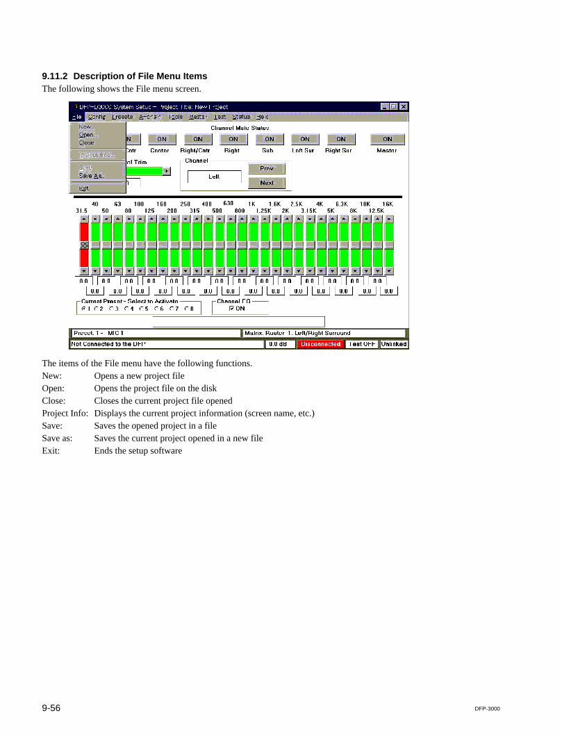
9-56 DFP-3000
9.11.2 Description of File Menu ItemsThe following shows the File menu screen.
The items of the File menu have the following functions.New: Opens a new project fileOpen: Opens the project file on the diskClose: Closes the current project file openedProject Info: Displays the current project information (screen name, etc.)Save: Saves the opened project in a fileSave as: Saves the current project opened in a new fileExit: Ends the setup software
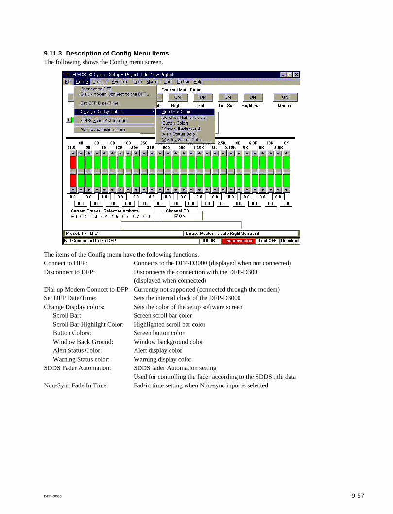
9-57DFP-3000
9.11.3 Description of Config Menu ItemsThe following shows the Config menu screen.
The items of the Config menu have the following functions.Connect to DFP: Connects to the DFP-D3000 (displayed when not connected)Disconnect to DFP: Disconnects the connection with the DFP-D300
(displayed when connected)Dial up Modem Connect to DFP: Currently not supported (connected through the modem)Set DFP Date/Time: Sets the internal clock of the DFP-D3000Change Display colors: Sets the color of the setup software screen
Scroll Bar: Screen scroll bar colorScroll Bar Highlight Color: Highlighted scroll bar colorButton Colors: Screen button colorWindow Back Ground: Window background colorAlert Status Color: Alert display colorWarning Status color: Warning display color
SDDS Fader Automation: SDDS fader Automation settingUsed for controlling the fader according to the SDDS title data
Non-Sync Fade In Time: Fad-in time setting when Non-sync input is selected

9-58 DFP-3000
9.11.4 Description of Preset Menu ItemsThe following shows the Preset menu screen.
The items of the Preset menu have the following functions.Preset Configuration: Setting screen of inputs, matrices, and levels corresponding to each presetActive Preset: Screen for switching presets from the PC

9-59DFP-3000
9.11.5 Description of A-Chain Menu ItemsThe following shows the A-Chain menu screen.
The items of the A-Chain menu have the following functions.AUX Inputs: Reference input level setting of each AUX inputPEC Inputs: PEC input adjustment menu
The following screen appears when this is selected.
Level Adjustments Oscilloscope: Displays the PEC signal level adjust-ment screen and wave
Focus/Azimuth and Slit loss EQ adjustments: Displays the PEC focus and azimuthadjustment support and slit loss EQsetting screen
Help: Recalls PEC input adjustment helpExit: Ends PEC input adjustments
Non-sync Inputs: For adjusting the Non-sync input levelMicrophone Inputs: Mic-Input level adjustment
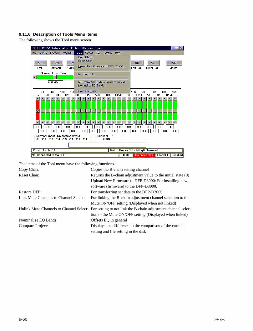
9-60 DFP-3000
9.11.6 Description of Tools Menu ItemsThe following shows the Tool menu screen.
The items of the Tool menu have the following functions.Copy Chan: Copies the B-chain setting channelReset Chan: Returns the B-chain adjustment value to the initial state (0)
Upload New Firmware to DFP-D3000: For installing newsoftware (firmware) to the DFP-D3000.
Restore DFP: For transferring set data to the DFP-D3000.Link Mute Channels to Channel Select: For linking the B-chain adjustment channel selection to the
Mute ON/OFF setting (Displayed when not linked)Unlink Mute Channels to Channel Select: For setting to not link the B-chain adjustment channel selec-
tion to the Mute ON/OFF setting (Displayed when linked)Nominalize EQ Bands: Offsets EQ in generalCompare Project: Displays the difference in the comparison of the current
setting and file setting in the disk
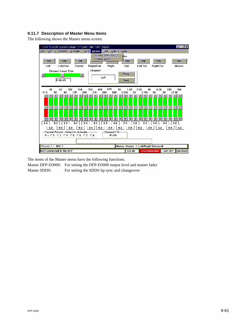
9-61DFP-3000
9.11.7 Description of Master Menu ItemsThe following shows the Master menu screen.
The items of the Master menu have the following functions.Master DFP-D3000: For setting the DFP-D3000 output level and master faderMaster SDDS: For setting the SDDS lip sync and changeover
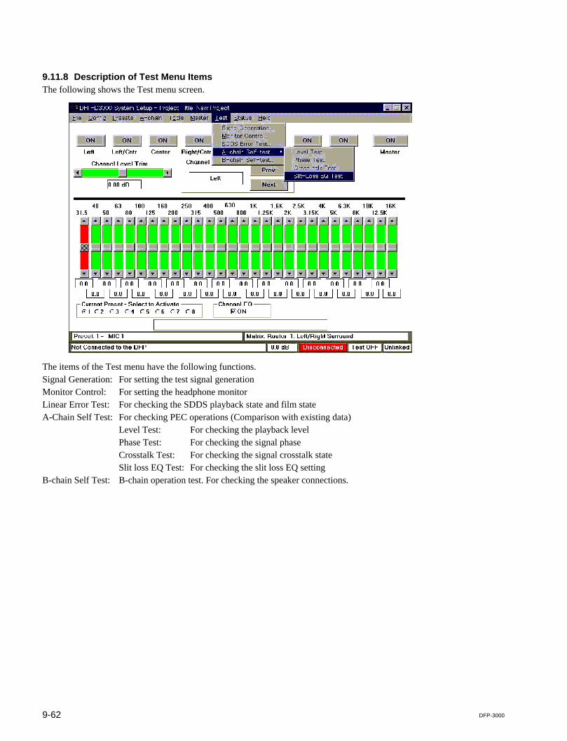
9-62 DFP-3000
9.11.8 Description of Test Menu ItemsThe following shows the Test menu screen.
The items of the Test menu have the following functions.Signal Generation: For setting the test signal generationMonitor Control: For setting the headphone monitorLinear Error Test: For checking the SDDS playback state and film stateA-Chain Self Test: For checking PEC operations (Comparison with existing data)
Level Test: For checking the playback levelPhase Test: For checking the signal phaseCrosstalk Test: For checking the signal crosstalk stateSlit loss EQ Test: For checking the slit loss EQ setting
B-chain Self Test: B-chain operation test. For checking the speaker connections.

9-63DFP-3000
9.11.9 Description of Help Menu ItemsThe following shows the Help menu screen.
The items of the Help menu have the following functions.Getting Started: For displaying the initial help screen and accessing the English help itemsKeyboard short Cuts: Description of keyboard short cutAbout: For displaying the software version, Build number, and Copy Right

DFP-3000
The material contained in this manual consists ofinformation that is the property of Sony Corporation.Sony Corporation expressly prohibits the duplication ofany portion of this manual or the use thereof for anypurpose other than the operation or maintenance of theequipment described in this manual without the expresswritten permission of Sony Corporation.
Le matériel contenu dans ce manuel consiste eninformations qui sont la propriété de Sony Corporation.Sony Corporation interdit formellement la copie dequelque partie que ce soit de ce manuel ou son emploipour tout autre but que des opérations ou entretiens del’équipement à moins d’une permission écrite de SonyCorporation.
Das in dieser Anleitung enthaltene Material besteht ausInformationen, die Eigentum der Sony Corporation sind.Die Sony Corporation untersagt ausdrücklich dieVervielfältigung jeglicher Teile dieser Anleitung oder denGebrauch derselben für irgendeinen anderen Zweck alsdie Bedienung oder Wartung der in dieser Anleitungbeschriebenen Ausrüstung ohne ausdrücklicheschriftliche Erlaubnis der Sony Corporation.

Printed in Japan
Sony Corporation 2001. 1 08
Communication System Solutions Network Company ©2000
DFP-D3000 (SY)
DFP-R3000 (SY) E
9-976-890-02