Embed Size (px)
Citation preview
World Meteorological OrganizationCommission for Instruments and Methods of Observation OPAG on Remote-Sensing TechnologiesJoint Session of the Expert Team on Operational In Situ Technologies (ET-OIST) and the Expert Team on Developments in In Situ Technologies (ET-DIST)Geneva, Switzerland, 21-23 June 2017
CIMO/ET-A1-A2/Doc. 7(1)Submitted by:
A. Dubovetskiy17.06.2017
PERFORMANCE OF NEW IN SITU TECHNOLOGIESUPPER AIR OBSERVATIONS
Summary and purpose of document
This document provides overview of the performance of new in the upper air observations.
ACTION PROPOSED
The Meeting is invited to take notice of the findings reported in this document and to decide whether the recommendations are appropriate.
________________
Appendix I:Tables and Pictures Appendix II: References
CIMO/ET-A1-A2/Doc. 7.1, p. 2
PERFORMANCE OF NEW IN SITU TECHNOLOGIES: UPPER AIR OBSERVATIONS
Introduction
Upper air observations includes as the radiosondes observations and the other observations using special platforms, specialized equipment, and aircraft, or made indirectly by remote-sensing instruments such as microwave radiometers and Raman water vapour lidars in the boundary layer and troposphere. Radiosonde systems are normally used to measure pressure, temperature and relative humidity. At most operational sites, the radiosonde system is also used for upper-wind determination. In addition, some radiosondes are flown with sensing systems for atmospheric constituents, such as ozone concentration or radioactivity. [1]
The most significant event to indicate the progress in radiosonde technology for the years was the 8th WMO Intercomparison of High Quality Radiosonde Systems in Yangjiang, China, 12 - 31 July 2010. The Intercomparison results was published in the WMO IOM Report 107, WMO/TD-No. 1580, 2011. And little bit later Dr. John Nash has revised a CIMO Guide (WMO 2010) information and include Intercomparision based changes to the own report (WMO IOM Report 121, 2015). [3]
There are some improvements in the in-situ upper-air observations have been made for the last years. Despite there are not a very new technologies was created in the measurement and electronic areas, but some interesting devices have been produced.
The progress in operational radiosonde technology for the years from the last Radiosonde Systems intercomparison is reviewed below. Table 1.1 shows the summary of changes for radiosondes have been made in 2010-2017 period.
Radiosonde observations
Radiosonde: Instrument intended to be carried by a balloon through the atmosphere, equipped with devices to measure one or several meteorological variables (pressure, temperature, humidity, etc.), and provided with a radio transmitter for sending this information to the observing station.
Radiosonde observation: An observation of meteorological variables in the upper air, usually atmospheric pressure, temperature, humidity and, often, horizontal wind, by means of a radiosonde.
CIMO/ET-A1-A2/Doc. 7.1, p. 3
Radiosonde dimensions and weight
The main changes have been made over the years after the last intercomparison in China are the radiosondes size and weight. Some manufacturers have reduced their radiosondes dimensions and weight. Such changes allow reducing a risk of consequences in the various situations, especially injury of the human. The light radiosonde weight also helps reduce gas consumption for balloon filling and balloon can reach more height during observation.
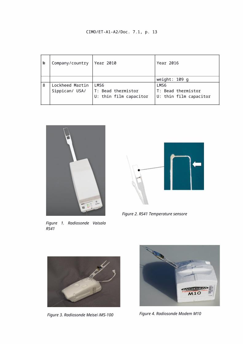
Meisei has made a very light weight radiosonde IMS-100 that has a 38g weight only (Fig. 3). This is a lightest operational radiosonde in the world for now. Downsizing of radiosonde (iMS-100) also results in higher measurement performance. One is to reduce adverse thermal effect influenced by radiosonde box since the volume of radiosonde package has been decreased by 70% from that of RS-11G (Meisei previous model). Second, pendulum motions of sonde package are reduced because the lightest-smallest package smoothly rides on the wind. [4]
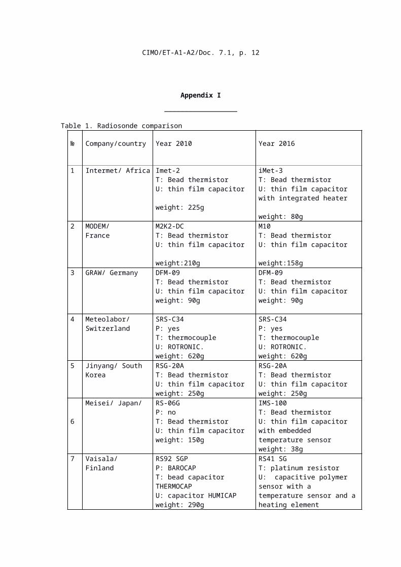
The Vaisala radiosonde RS41 SG has a 109g weight (Fig. 1).
The Modem radiosonde M10 has a 158g weight (Fig. 3).
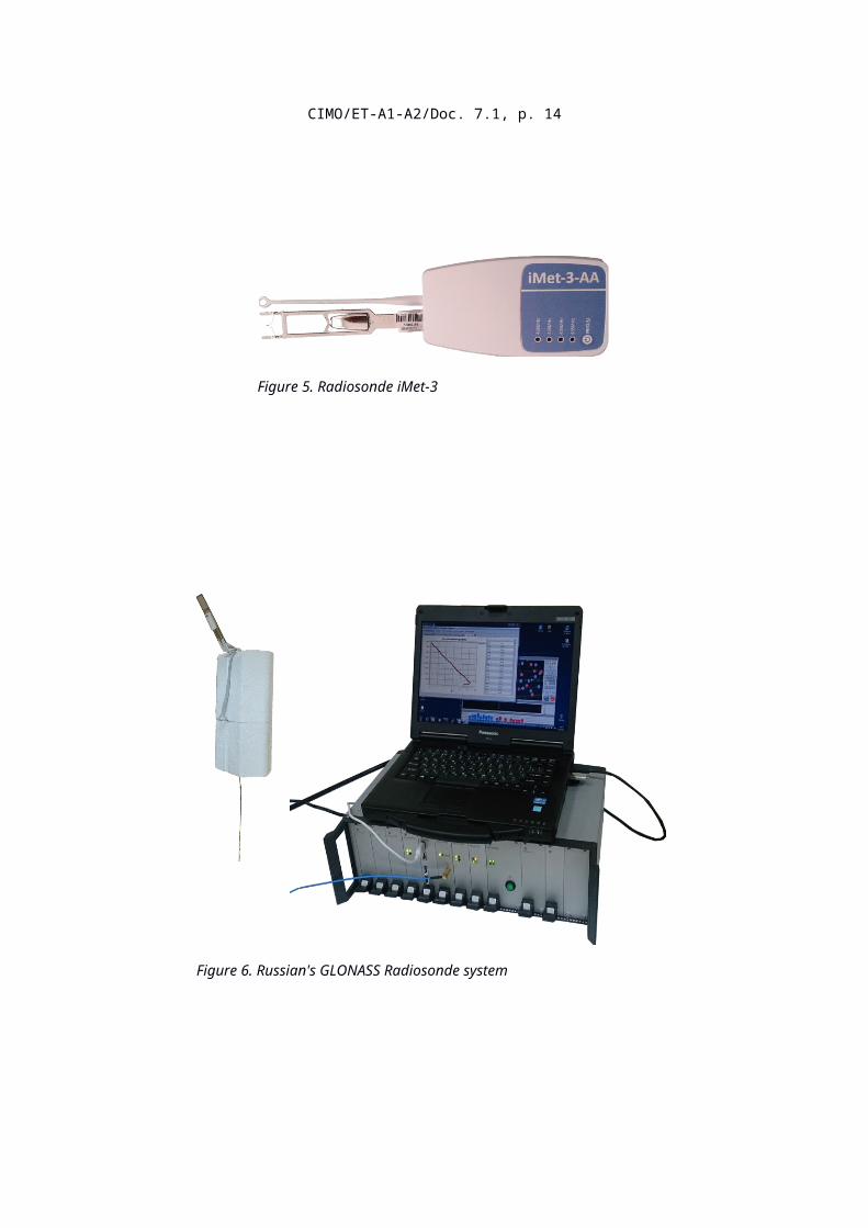
The iMet-3 radiosonde by Intermet has a 80g weight (Fig 4).
The performance of the current technology allow to reduce such significant for the public safety parameters as dimensions and weight. It’s a very important improvement for now. It does also allow to make radiosondes more environmental friendly. Seems to be all of the manufacturers will modify their radiosondes to small and light devices in the near future.
Recommendations
Consider the necessity and possibility to recommend to manufacturers to reduce the size and the mass of their radiosondes
Temperature sensors
Almost all of the manufacturers still use the technology they had in 2010. The most of them are using a bead thermistor technology for temperature measurement.
But some of them have made an improvement in their technologies to make the temperature measurement more efficient.
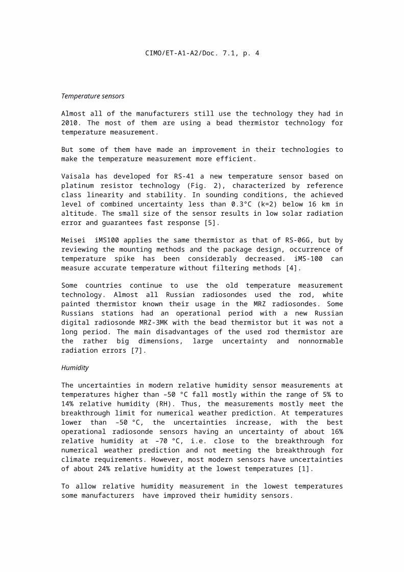
Vaisala has developed for RS-41 a new temperature sensor based on platinum resistor technology (Fig. 2), characterized by reference class linearity and stability. In sounding conditions, the achieved level of combined uncertainty less than 0.3°C (k=2) below 16 km in altitude. The small size of the sensor results in low solar radiation error and guarantees fast response [5].
Meisei iMS100 applies the same thermistor as that of RS-06G, but by reviewing the mounting methods and the package design, occurrence of temperature spike has been considerably decreased. iMS-100 can measure accurate temperature without filtering methods [4].
CIMO/ET-A1-A2/Doc. 7.1, p. 4
Some countries continue to use the old temperature measurement technology. Almost all Russian radiosondes used the rod, white painted thermistor known their usage in the MRZ radiosondes. Some Russians stations had an operational period with a new Russian digital radiosonde MRZ-3MK with the bead thermistor but it was not a long period. The main disadvantages of the used rod thermistor are the rather big dimensions, large uncertainty and nonnormable radiation errors [7].
Humidity
The uncertainties in modern relative humidity sensor measurements at temperatures higher than –50 °C fall mostly within the range of 5% to 14% relative humidity (RH). Thus, the measurements mostly meet the breakthrough limit for numerical weather prediction. At temperatures lower than –50 °C, the uncertainties increase, with the best operational radiosonde sensors having an uncertainty of about 16% relative humidity at –70 °C, i.e. close to the breakthrough for numerical weather prediction and not meeting the breakthrough for climate requirements. However, most modern sensors have uncertainties of about 24% relative humidity at the lowest temperatures [1].
To allow relative humidity measurement in the lowest temperatures some manufacturers have improved their humidity sensors.
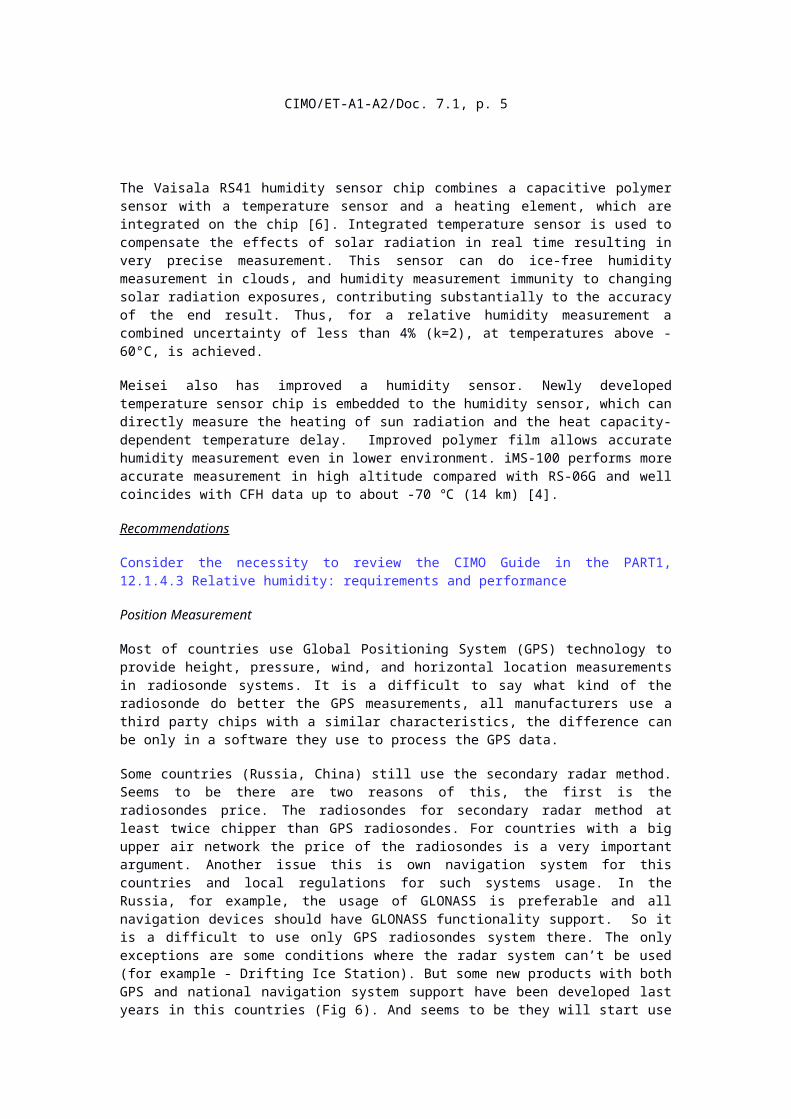
The Vaisala RS41 humidity sensor chip combines a capacitive polymer sensor with a temperature sensor and a heating element, which are integrated on the chip [6]. Integrated temperature sensor is used to compensate the effects of solar radiation in real time resulting in very precise measurement. This sensor can do ice-free humidity measurement in clouds, and humidity measurement immunity to changing solar radiation exposures, contributing substantially to the accuracy of the end result. Thus, for a relative humidity measurement a combined uncertainty of less than 4% (k=2), at temperatures above -60°C, is achieved.
Meisei also has improved a humidity sensor. Newly developed temperature sensor chip is embedded to the humidity sensor, which can directly measure the heating of sun radiation and the heat capacity-dependent temperature delay. Improved polymer film allows accurate humidity measurement even in lower environment. iMS-100 performs more accurate measurement in high altitude compared with RS-06G and well coincides with CFH data up to about -70 ℃ (14 km) [4].
Recommendations
Consider the necessity to review the CIMO Guide in the PART1, 12.1.4.3 Relative humidity: requirements and performance
Position Measurement
Most of countries use Global Positioning System (GPS) technology to provide height, pressure, wind, and horizontal location measurements in radiosonde systems. It is a difficult to say what kind of the radiosonde do better the GPS measurements, all manufacturers use a third party chips with a similar characteristics, the difference can be only in a software they use to process the GPS data.
Some countries (Russia, China) still use the secondary radar method. Seems to be there are two reasons of this, the first is the radiosondes price. The radiosondes
CIMO/ET-A1-A2/Doc. 7.1, p. 5
for secondary radar method at least twice chipper than GPS radiosondes. For countries with a big upper air network the price of the radiosondes is a very important argument. Another issue this is own navigation system for this countries and local regulations for such systems usage. In the Russia, for example, the usage of GLONASS is preferable and all navigation devices should have GLONASS functionality support. So it is a difficult to use only GPS radiosondes system there. The only exceptions are some conditions where the radar system can’t be used (for example - Drifting Ice Station). But some new products with both GPS and national navigation system support have been developed last years in this countries (Fig 6). And seems to be they will start use Global Navigation Satellite Systems (GNSS) radiosondes very soon. Expected that usage of the radiosondes with GNSS will improve sounding quality.
The series of the radiosondes manufacturers outside of the Russia have expressed their support of the GLONASS technology for now. This became possible due to the World Bank’s Second National Hydromet System Modernization Project (Roshydromet-2). In this project there is a tender with a delivery of some amount of the radiosonde systems with GNSS support.
Radiosonde data transmission protocol
All manufactures use own, proprietary protocol for radiosonde data transmission. But there are some situations when the common standard of the data transmission will be very useful for the customers. The first is a possibility to use various types of radiosondes on a single ground station. The second idea is - the radiosonde can be tracked both on the ascent and on the descent, but radiosonde on the descent, due to long distance flight posiibility, often is not visible by the station near the ground surface. It is possible to create a not expensive ground stations net to make possibility track any type of radiosonde in any point. It will allow to use all information from radiosonde during whole flight. The issue only the all radiosondes should use the parachute on the descent flight for vertical speed limitation.
Recommendations
My proposal is to consider the possibility of development and implementation the common standard for the data transmission protocol from radiosonde to ground station.
Wind measurements
The wind measurement principle has well described in [1]: A radiosonde with the capability of receiving signals from a system of navigational radio transmitters is attached to a target (either an ascending balloon or dropsonde parachute). The most widely used system is to use signals from navigation satellites. In practice, for the moment, this means using the NAVSTAR GPS signals, although other, more recently introduced satellite radionavigation services may be used in the future. The signals from the satellites are received by a dedicated antenna on the radiosonde. The system will also have a GPS antenna on the ground to receive signals for reference. A GPS engine, either on the ground or in the radiosonde, will decode the signals or allow computation of the radiosonde position in three dimensions as a function of time.
CIMO/ET-A1-A2/Doc. 7.1, p. 6
Some companies have developed small size and weight devices for wind measurements using system navigation signals. This radiosondes do not used in any operational practice but they can be used in a cases when there are only wind measurement requirements as a standard upper-air observations alternative.
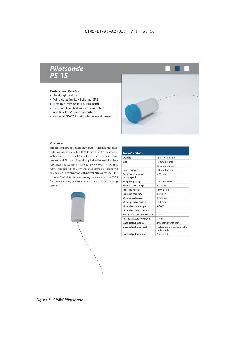
GRAW Pilotsonde PS-15 (Germany). The pilotsonde PS-15 (Fig. 8) is based on the GRAW radiosonde system DFM. In fact, it is a GPS radiosonde without sensors for humidity and temperature. It can replace conventional Pilot soundings with optical radiotheodolites by a fully automatic sounding system at very low costs [8].
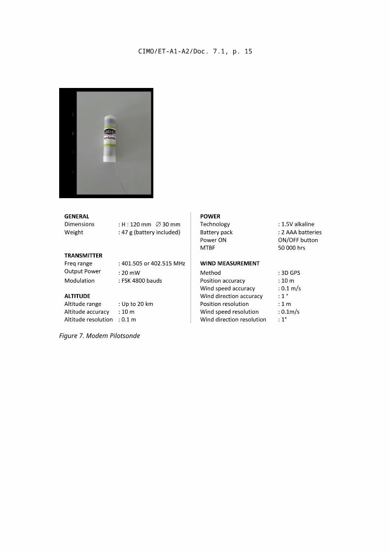
Modem PilotSonde (France). This tiny GPS radiosonde (Fig. 7) without Temperature and Humidity sensors is the alternative to theodolite optical devices to perform Pilotsounding [9].
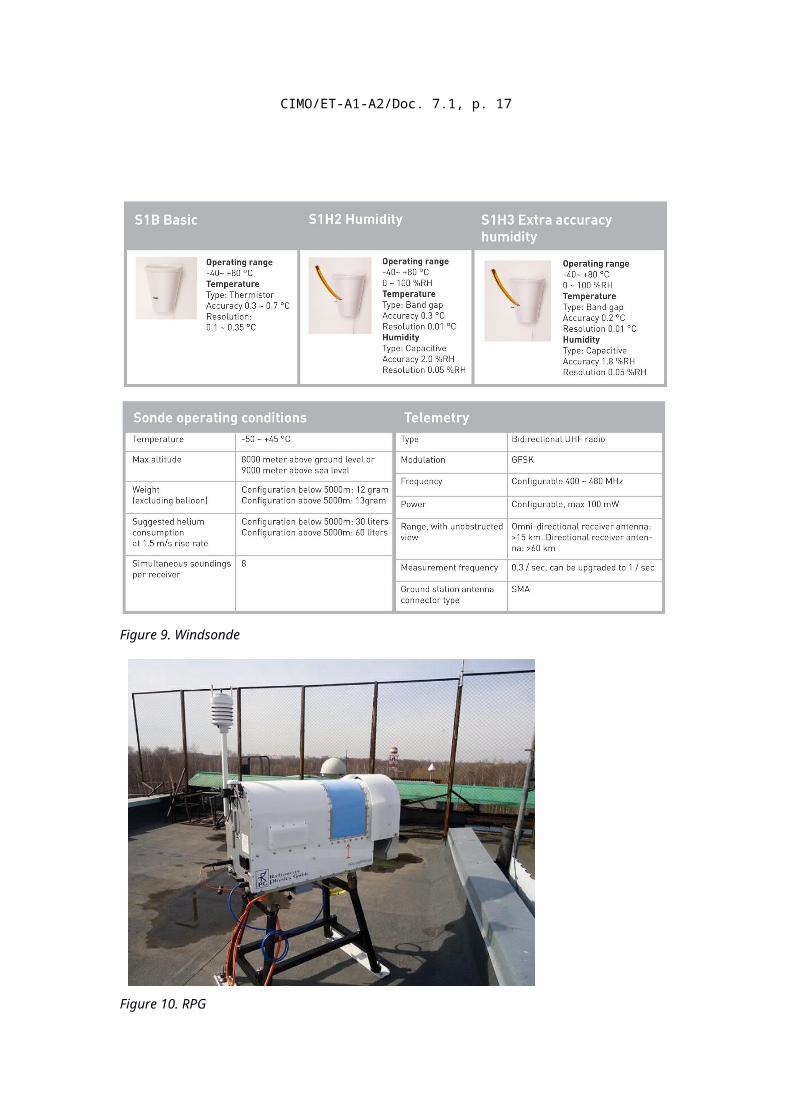
Windsond Radiosonde S1 (Sweden). Windsond (Fig. 9) is a weather balloon system for an immediate view of local conditions at different altitudes. The focus on portability and low operating costs makes it perfect for frequent use in the field. It is not only a pilotsonde. It has temperature and humidity onboard sensors, but due to the low maximum altitude performance (about 8-9km) this sonde cannot be used for operational observations [10].
Automatic radiosonde launchers
For the last years some manufacturers has developed an automatic balloon launchers for upper-air sounding. The main advantages of such systems usage are [12]:
Make the operator’s tasks easier (easy maintenance and low rate of failure), reduce the possibility of human error and wrong handling during preparation/launch phase
Increase percentage of successful soundings
Enhanced security of operation using hydrogen
Facilitate staff management during out of normal working hours (night or week-end, and/or remote location)
Affordable acquisition and maintenance allowing savings on global running cost
The main features for all launchers are similar:
Radiosonde automatic activation and test
Automatic balloon inflation: The system monitors a gas flow meter to inflate the balloon according to a specified volume. Compatible with helium or hydrogen gas
Automatic releasing the radiosonde at specified launch times
Data acquisition and storage in real time Automatic generation and transmission of messages (TEMP, BUFR...)
CIMO/ET-A1-A2/Doc. 7.1, p. 7
Re-launch of a radiosonde in case of an incident before the balloon release or failure during the flight
Possible immediate launch by an operator
Log of events
Daily report
Alert message in case of dysfunction
The next automatic radiosonde launchers have been developed for now:
Modem(France): Robotsonde [12];
Vaisala(Finland): Autosonde [13];
Yankee(USA): Automated Radiosonde Launcher (ARL-9000);
Meisei(Japan): Automated Radiosond Systems(ARS);
Nanjing Daqiao(China): Fully Automated Sounding System [11];
The automatic launchers was mounted on such observation stations as Tasiilaq(DMI) (Modem Robosonde), Jang Bogo(Korean Antarctic station)(Vaisala Autosonde), etc.
The usage of these systems in all climate conditions, from cold polar climate to tropical, shows that automatic launchers are very useful for unattended upper-air observations.
Special observations
Some special radiosondes are used for the specific observation as ozone, cloud particle measurements, aerosol, radioactivity, cloud detection.
Optical detection of cloud by a radiosonde.
There are a number of works related to optical detection of the cloud boundaries for the last years. Optical detection of cloud from meteorological radiosondes can increase the vertical resolution over the standard thermodynamic methods. It can also help to detect thin clouds which would otherwise be poorly identified due to the time constants of capacitance sensors[optical 1]. The base principle of cloud detection is using as an additional radiosonde sensor. There are some differences in implementation of cloud detection realization.
In [14] authors used a backscatter principle. They have used an ultra-bright light emitting diode (LED) illumination source with a photodiode detector. Scattering of the LED light by cloud droplets generates a small optical signal which is separated from background light fluctuations using a lock-in technique. The signal to noise obtained permits cloud detection using the scattered LED light, even in daytime. The response is interpreted in terms of the equivalent visual range within the cloud.
CIMO/ET-A1-A2/Doc. 7.1, p. 8
In [15], [16] author has used the photodiode of generating type (sensitive visible and near-infrared regions of the spectrum) for cloud top height detection. The base question of such detections is a representative. The radiosondes observation is not so frequently event, radiosonde intersect the cloud in one point (in the projection). So it is sightly difficult to estimate usefulness of such detections.
Observations with gliders
The first glider usage for the radiosounding purposes was introduced by Oliver Gebauer in 2012 [17]. He proposed a system based on a pretty big sailplane with possibility to use any onboard sensors. The sailplane should be launched with the weather balloon, released after balloon burst and then flight and landing with autopilot and GPS navigation. It was not a useful development, because the big airplane is a potential danger for civil aircrafts and can lead to accidents. So to use such devices the special permission from air traffic control authorities is necessary. But it is almost impossible to get such permissions.
Some companies from various countries had tried to make the similar developments.
In the [18] authors had described the development of the Return glider radiosonde (RGR) with solar and infrared radiation measurement possibility. In the paper they have done the detailed description of the test result. And they also have described safety features of the RGR usage. The developers had contacted to relevant authorities during the test flights and they got permissions, but it was a special case. In my mentions it cannot be done for the regular operational observations, only for scientific purposes.
The observations using a returnable gliders looks are very interesting, but such observations can be useful only for scientific researches, when expensive instruments are launching with balloon and return of the instruments is the necessary condition.
Developments in the remote sensing technology
Technology for temperature and humidity profiles up to 10 km
RPG’s Generation 5 by Radiometer Physics GMBH
A major progress in G5 has been achieved in radiometer calibration accuracy and repeatability. RPG has developed a novel liquid nitrogen (LN2) cooled precision calibration target (PT-V1) with an absolute radiation temperature accuracy of ±0.1 K. G5 radiometers are equipped with a totally reworked data acquisition system. Its key feature is a 20 times faster channel sampling rate (4000 samples / sec / channel) which enables the receivers to efficiently take advantage of the noise injection system (noise adding radiometer). The new G5
CIMO/ET-A1-A2/Doc. 7.1, p. 9
radiometers provide an interface to a more sophisticated multi-channel IRR which is currently under development at RPG. This instrument will be significantly improved in terms of thermal stability to be operated in a wider environmental temperature range and provides more spectral features [19].
Measuring complex Microradkom by Central Aerological Observatory, Russia
Microradkom (Fig. 11) provide nearly continuous measurements of temperature profiles of the troposphere (with detailing on a separate channel of the atmospheric boundary layer temperature profiles), total water vapor content (moisture content of the atmosphere), the total content of the liquid water in the atmosphere (water content of clouds), the measurement of surface meteorological parameters, as well as video of clouds in zenith direction [20][21].
The above devices have similar possibilities and such devices are very useful to obtain the temperature and humidity profiles during the period between the radiosondes observations.
GNSS-PW measurements
Ground-based GNSS (Global Navigation Satellite Systems) PW was identified as a Priority 1 measurement for GRUAN [22]. Ground-based GNSS observations are used to estimate the equivalent excess propagation path in the zenith direction, which is referred as zenith total delay (ZTD). Inferring the atmospheric PW from the ZTD requires a value of the ground pressure at the site in order to infer the Zenith Wet Delay (ZWD) and a mean temperature of the atmosphere defined by weighting the temperature profile with the profile of the wet refractivity above the site.
There are series of national GNSS-PW networks for integrated water vapor( IWV) estimation. These networks consist in total more than 1300 stations, but basically they use only GPS signals for zenith total delay estimation.
A number of multi-GNNS (BeiDou, Galileo, GLONASS, and GPS) receivers have been developed for the last years, and the development of multi-Global Navigation Satellite Systems and the International GNSS Service Multi-GNSS Experiment brings great opportunities and challenges for real-time determination of tropospheric zenith total delays and integrated water vapor to improve numerical weather prediction, particularly for nowcasting or severe weather event monitoring. The accuracy of real-time single-system ZTD is about 10–20 mm, the accuracy of real-time ZTD estimation can be significantly improved to be about several millimeters (i.e., about 1.0–1.5 mm in IWV) when multi-GNSS observations are processed simultaneously. [23]
CIMO/ET-A1-A2/Doc. 7.1, p. 10
Appendix I__________________
Table 1. Radiosonde comparison
№ Company/country Year 2010 Year 2016
1 Intermet/ Africa Imet-2T: Bead thermistorU: thin film capacitor
weight: 225g
iMet-3T: Bead thermistorU: thin film capacitor with integrated heater
weight: 80g2 MODEM/
FranceM2K2-DСT: Bead thermistorU: thin film capacitor
weight:210g
M10T: Bead thermistorU: thin film capacitor
weight:158g3 GRAW/ Germany DFM-09
T: Bead thermistorU: thin film capacitorweight: 90g
DFM-09T: Bead thermistorU: thin film capacitorweight: 90g
4 Meteolabor/ Switzerland
SRS-C34P: yesT: thermocoupleU: ROTRONIC.weight: 620g
SRS-C34P: yesT: thermocoupleU: ROTRONIC.weight: 620g
5 Jinyang/ South Korea
RSG-20AT: Bead thermistorU: thin film capacitorweight: 250g
RSG-20AT: Bead thermistorU: thin film capacitorweight: 250g
6
Meisei/ Japan/ RS-06GP: noT: Bead thermistorU: thin film capacitorweight: 150g
IMS-100T: Bead thermistorU: thin film capacitor with embedded temperature sensorweight: 38g
7 Vaisala/Finland
RS92 SGPP: BAROCAPT: bead capacitor THERMOCAPU: capacitor HUMICAPweight: 290g
RS41 SGT: platinum resistorU: capacitive polymer sensor with a temperature sensor and a heating elementweight: 109 g
8 Lockheed Martin Sippican/ USA/
LMS6T: Bead thermistorU: thin film capacitor
LMS6T: Bead thermistorU: thin film capacitor
CIMO/ET-A1-A2/Doc. 7.1, p. 11
Figure 5. Radiosonde iMet-3
Figure 6. Russian's GLONASS Radiosonde system
CIMO/ET-A1-A2/Doc. 7.1, p. 12
Figure 7. Modem Pilotsonde
CIMO/ET-A1-A2/Doc. 7.1, p. 13
Figure 8. GRAW Pilotsonde
CIMO/ET-A1-A2/Doc. 7.1, p. 14
Figure 9. Windsonde
Figure 10. RPG
CIMO/ET-A1-A2/Doc. 7.1, p. 15
Figure 11. Measurement complex Microradcom
CIMO/ET-A1-A2/Doc. 7.1, p. 16
Appendix II
___________________
References:
[1] WMO Guide to Meteorological Instruments and Methods of Observation, WMO-No.8, 2014.
[2] WMO INTERCOMPARISON OF HIGH QUALITY RADIOSONDE SYSTEMS Yangjiang, China, 12 July 3 August 2010, WMO IOM Report 107, WMO/TD-No. 1580, 2011
[3] MEASUREMENT OF UPPER-AIR PRESSURE, TEMPERATURE AND HUMIDITY, John Nash (United Kingdom) IOM No.121
[4] Challenges of downsizing (Development of micro radiosonde iMS-100) Kensaku Shimizu, Ryota Maeda, Takehiko Sawada, Norio Nagahama Meisei Electric Co., Ltd. , 2223 Naganuma-cho, Isesaki City, Gunma, 372-8585, Japan, WMO, IOM-116, TECO-2014
[5] Vaisala Radiosonde RS41, Datasheet
[6] Vaisala Radiosonde RS41 Measurement Performance White paper.
[7] SI TRACEABILITY OF VAISALA RADIOSONDE RS41 SOUNDING DATA – CALIBRATION AND UNCERTAINTY ANALYSIS, Petteri Survo, Raisa Lehtinen and Jari Kauranen, Vaisala
[7] Upper Air Instrumentation in Russia, Dr. Andrey Dubovetskiy, Mr. Alexander Kats, WMO IOM Report No. 125, TECO-2016
[8] Upper Air Sounding Systems, Product brochure, GRAW, http://www.graw.de/products/radiosondes/ps-15/
[9] Meteomodem, PilotSonde, http://www.meteomodem.com/pilotsonde.html
[10] Windsond, http://windsond.com/
[11] Study and Development on Fully Automated Sounding System, LI Wei, HUANG Jiangping. WMO, IOM-109, TECO-2012
[12] Meteomodem, Robotsonde, http://www.meteomodem.com/robotsonde.html
[13] Automatic Sounding Station Vaisala AUTOSONDE www.vaisala.com
[14] Active optical detection of cloud from a balloon platform, R. G. Harrison and K. A. Nicoll, Review of Scientific Instruments No. 85, 2014
CIMO/ET-A1-A2/Doc. 7.1, p. 17
[15] THE MEASURING OF HEIGHT OF THE BOUNDARY BETWEEN THE TROPOSPHERE AND THE STRATOSPHERE Kochin A. V. Central aerological observatory, Roshydromet, WMO IOM Report No. 125, 2016
[16] Measurement of the cloud top height by a radisonde Kochin A. V. Central aerological observatory, Roshydromet, WMO IOM Report No. 125, 2016
[17] The reusable radiosonde, Oliver Gebauer, GeoSpy Aerial Imaging & Mapping, 2012
[18] Return glider radiosonde for insitu upper-air research measurements amt-9-2535-2016
[19] G5 Radiometer Improvements_2016.pdf
[20] Results of tropospheric thermodynamics monitoring by the multichannel ground ‐ based microwave system “Microradcom” WMO IOM-116, TECO-2014
[21] Study of liquid water in clouds with the “Microradkom” radiometric system, Atmospheric and Oceanic Optics, November 2014, Volume 27, Issue 6
[22] GRUAN Ground-based GNSS Site Guidelines. GRUAN-TD-6
[23] Multi-GNSS Meteorology: Real-Time Retrieving of Atmospheric Water Vapor From BeiDou, Galileo, GLONASS, and GPS Observations, Xingxing Li, Galina Dick, Cuixian Lu, Maorong Ge, Tobias Nilsson, Tong Ning, Jens Wickert, and Harald Schuh, IEEE TRANSACTIONS ON GEOSCIENCE AND REMOTE SENSING, VOL. 53, NO. 12, DECEMBER 2015


![Protocol Rollback and Network Security · (A2) test statistic [9] to determine if the observations are consistent with a uniform distribution. In particular, we use the implementation](https://img.pdfslide.us/doc/110x75/5e2a6a2b6574ef5160460b77/protocol-rollback-and-network-security-a2-test-statistic-9-to-determine-if-the.jpg)