Embed Size (px)
Citation preview

CIGRE’ – GRID OF THE FUTURE 2017, OCTOBER 23-25 CLEVELAND, OHIO
First Energy – ABBMaint a ining Grid St ab ilit y Am id s t Genera t ion Ret irem entJohn Syner, Genera l Manag er Trans m is s ion Planning First Energy Anders Bost rom, Lead Engineer ABB FACTS

1:30PM – 5:30 PM, b reak 3PM – 3:15PM
Backg round – Drivers Behind Genera t ion Ret irem entTransm is s ion Sys t em Asp ect sThe First Energy Experience
React ive Power– Syst em St abilit y & Transmission Capabilit yShunt & Series Compensat ion
Technology Overview – SVC, SC, STATCOM, Series Compensat ionThe First Energy SCs & SVCs
Auxiliary Syst ems – Syst em & device propert ies, C&P, Auxiliary Syst ems
Operat ion & Maint enance
Discussion & Wrap-up
Present at ion Out line
November 10, 2017 Slide 2
Maint aining Grid St abilit y Amidst Generat ion Ret irement

November 10, 2017 Slid e 3
Background
Transmission Syst em Aspect s
Drivers Behind Generat ion Ret irement
The First Energy Experience

November 10, 2017 Slid e 4
Maint aining Grid St abilit y – Generat ion Mix
Source: US Energ y Inform at ion Ad m inis t ra t ion, ht t p s :/ / www.eia .g ov
2016 – 4,100 TWh
Nat ural gas 33.8%
Coal 30.4%
Nuclear 19.7%
Renewables (t o t a l) 14.9%
Ot her sources 1.0%

Drivers Behind Coal Ret irement
– Aging and inef f icient coal f leet
– Rising const ruct ion cost
– St able or falling nat ural gas price
– Increasing coal price
– Falling cost of renewables
– Slowing load growt h
– US Coal f ired generat ion fell f rom 50 % t o 37 % f rom 2008 t o 2012
November 10, 2017 Slide 5
(Compet it ive)
(non compet it ive) Source: Lesley Fleischman, Rachel Cleetus, Jef f Deyet t e, Steve Clemmer, Steve Frenkel. Ripe for Ret irement :An Economic Analysis of t he U.S. Coal Fleet . The Elect ricit y Journal, Volume 26, Issue 10, December 2013, Pages 51–63.

Drivers Behind Coal Ret irement
– Environment al Aspect s – new air regulat ory requirement s
– Aging Baseload Generat ing Asset sCoal gen. high performance lifet ime t ypically 25 – 30 years before out age f requency and maint enance increases
– Fuel Cost – reduced prof it margins Coal price doubled bet ween 2000-2010 while nat ural gas reduced by 50 %.
– Dropping Load Growt h – syst em oversupply– Falling Cost for Renewables – wind and
solar PV
November 10, 2017 Slide 6
Source: US Energy Informat ion Administ rat ion, ht t ps:/ / www.eia.gov
BTU = Brit ish Thermal Unit , 1 BTU = 1055 J or t he amount of heat required t o raise t he t emperature of one pound of water by one degree F.

– Cont inued op era t ion hig hly unp rofit ab le fo r a num b er o f p lant s
– True even wit hout s crub b er up g rad es– Ad d ing or re t ro fit t ing s crub b ers cos t ly
An ERCOT Exam p le – Scrub b er Ret ro fit t ing
Novem b er 10 , 20 17 Slid e 7
Drivers Behind Coal Ret irementProf it abilit y of Coal Fired Generat ion,IEEEFA b ase case s cena rio (annua l ne t p re-t ax ea rning s 2017-2024)
Source:The Beg inning of The End , fund am ent a l chang e in t he energ y m arket s a re und erm ining t he financia l viab ilit y o f coa l fired p ower p lant s in Texas . David Schlis s el, Ins t it ut e fo r Energ y Econom ics and Financia l Ana lys is

ERCOT Annual Wind Generat ion Percent age of Tot al Generat ion
Novem b er 10 , 20 17 Slid e 8
Renewables
Source: ERCOT Energ y b y fuel t yp e 20 0 2-20 15, ava ilab le a t ht t p :/ / erco t .com / news / p res ent a t ions

– Genera t ion cap acit y t o m eet exp ect ed d em and and s a t is fy Resource Ad eq uacy req uirem ent s
– Sufficient recourses t o p rovid e cont inuous sup p ly reg ard les s o f out ag es , s ched uled or unsched uled
– Sys t em ab ilit y t o wit hs t and unp lanned , unexp ect ed cont ing encies –Transmission Securit y
– Meet loca l source req uirem ent s –b a lancing g enera t ion and load
Planning Res erve Marg in
Novem b er 10 , 20 17 Slid e 9
Impact on Syst em Reliabilit y
Source: Exis t ing and p lanned cap acit y a re b as ed on ERCOT’s May 20 16 CDR; coa l a t ris k o f re t irem ent is b as ed on Bra t t le’s ana lys is

– Cont ro l a rea load and g enera t ion has t o b e in b a lance
– Renewab les increas e need fo r Ag ile Ram p ing Power– The t yp ica l la rg e coa l-fired t herm al g enera t o r is
ab le t o ram p ap p roxim at e ly 1 % of it s cap acit y p er m inut e
– Sm aller unit s and com b us t ion t urb ines a re fas t er– Reg ula t ion d efinit ions varies b e t ween reg ions
PJM/ ISO-NE 5 m in. ram p ing cap ab ilit yERCOT 15 m in.WECC 10 Min.
– NERC Cont ro l Perfo rm ance St and ard d et erm ines t he p erm is s ib le im b a lance o f a cont ro l a rea on 1 m inut e and 10 m inut e b as is .
Ram p ing Power
Novem b er 10 , 20 17 Slid e 10
Impact on Syst em Reliabilit y

– Act ive Power Deficit Freq uency d rop
– Act ive p ower surp lus Freq uency increase
– Relies on t urb ine g overnor cont ro l – primary cont rol
– and p lanning reserve – secondary cont rol
– Renewab le Genera t ion will ram p oft en
– Renewab les a re t yp ica lly non resp ons ive t o freq uency chang es o r BA load freq uency com m and s
Freq uency Cont ro l
Novem b er 10 , 20 17Balancing Aut horit y - The res p ons ib le ent it y t ha t int eg ra t es res ource p lans ahead of t im e, m aint a ins load int e rchang e-g enera t ion b a lance wit hin a Balancing Aut horit y Area , and s up p ort s Int e rconnect ion freq uency in rea l t im eSlid e 11
Impact on Syst em Reliabilit y

Syst em Fault Level
Impact on Syst em Reliabilit y
Novem b er 10 , 20 17 Slid e 12
Source: Na t iona l Grid Elect ricit y UKTen Year St a t em ent

November 10, 2017 Slid e 13
Source: Na t iona l Grid Elect ricit y Ten Year St a t em ent
Impact on Syst em Reliabilit ySys t em Fault Level
– Fault Level ~ sys t em s t reng t h
– Trans ferring Cap ab ilit y
– Ang ula r s t ab ilit y
– Volt ag e St ab ilit y
– Select ive sys t em p ro t ect ion
– Suscep t ib ilit y t o ha rm onic d is t o rt ion
– Wit h f alling f ault levels, t ransmission syst ems are becoming more suscept ible t o dist urbance – periods of varying volt age and f requency

Shif t of Syst em Resonance t o Low Order Harmonics
Impact on Syst em Reliabilit y
Novem b er 10 , 20 17 Slid e 14 Source : Nat iona l Grid Elect ricit y Ten Year St a t em ent

Shif t of Syst em Resonance t o Low Order Harmonics
Impact on Syst em Reliabilit y
Novem b er 10 , 20 17 Slid e 15
Network impedance will change over time due to different load scenarios, system configurations, contingencies, generation etc.
Resonance frequencies and system damping is affected by;
Number of connected shunt capacitor banks – systems tend to become over compensated
Cable and T-line charging capacitance
Parallel FACTS and HVDC installations
System loading (active and reactive)
Often results in severe harmonic amplification

First Energy Company Overview
– 65,000-square-mile service t errit ory
– 10 operat ing companies in 6 st at es
– 6 Million cust omers
– 4 t ransmission companies
– Approximat ely 24,500 miles of t ransmission lines
– Nearly 17,000 MW of generat ion capacit y
November 10, 2017 Slide 16

PJM Syst em
– Generat ing dispat ch capacit y: 176,560 MW
– 2016 peak demand: 152,131 MW
– Transmission lines: 82,540 miles
– Populat ion served: 65 million in 13 st at es and Dist rict of Columbia
– Over 990 members
November 10, 2017 Slide 17
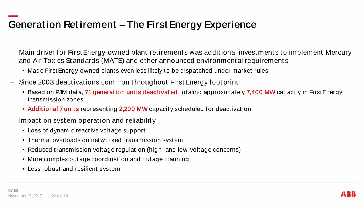
Generat ion Ret irement – The First Energy Experience
– Main driver for First Energy-owned plant ret irement s was addit ional invest ment s t o implement Mercury and Air Toxics St andards (MATS) and ot her announced environment al requirement s • Made FirstEnergy-owned plant s even less likely t o be dispat ched under market rules
– Since 2003 deact ivat ions common t hroughout First Energy foot print• Based on PJM data, 71 generat ion unit s deact ivat ed t otaling approximately 7,400 MW capacit y in FirstEnergy
t ransmission zones• Addit ional 7 unit s represent ing 2,200 MW capacit y scheduled for deact ivat ion
– Impact on syst em operat ion and reliabilit y• Loss of dynamic react ive volt age support• Thermal overloads on networked t ransmission system• Reduced t ransmission volt age regulat ion (high- and low-volt age concerns)• More complex outage coordinat ion and outage planning• Less robust and resilient system
November 10, 2017 Slide 18

Generat ion Deact ivat ion
From PJM websit e www.pjm.com
November 10, 2017 Slide 19

From PJM websit e www.pjm.com
GENERATOR PROPOSED DEACTIVATIONS In FE Zones 2012 - 2013(as of October 4, 2017)
Unit CapacityTransZone Age (Years)
Official Owner Request
Deactivation Date
Actual Deactivation Date
Niles 2 108 ATSI 58 2/29/2012 6/1/2012 6/1/2012
Armstrong 1 172 AP 53 1/26/2012 9/1/2012 9/1/2012
Armstrong 2 171 AP 52 1/26/2012 9/1/2012 9/1/2012
Bay Shore 2 138 ATSI 53 1/26/2012 9/1/2012 9/1/2012Bay Shore 3 142 ATSI 48 1/26/2012 9/1/2012 9/1/2012Bay Shore 4 215 ATSI 43 1/26/2012 9/1/2012 9/1/2012
Eastlake 4 240 ATSI 55 1/26/2012 9/1/2012 9/1/2012
Eastlake 5 597 ATSI 39 1/26/2012 9/1/2012 9/1/2012R Paul Smith 3 28 AP 64 1/26/2012 9/1/2012 9/1/2012R Paul Smith 4 87 AP 43 1/26/2012 9/1/2012 9/1/2012Albright 1 73 APS 59 2/8/2012 9/1/2012 9/1/2012
Albright 2 73 APS 59 2/8/2012 9/1/2012 9/1/2012Albright 3 137 APS 57 2/8/2012 9/1/2012 9/1/2012Rivesville 5 35 APS 68 2/8/2012 9/1/2012 9/1/2012Rivesville 6 86 APS 60 2/8/2012 9/1/2012 9/1/2012Willow Island 1 51 APS 63 2/8/2012 9/1/2012 9/1/2012Willow Island 2 138 APS 51 2/8/2012 9/1/2012 9/1/2012
Niles 1 109 ATSI 58 2/29/2012 6/1/2012 10/1/2012
Piney Creek NUG 31 PenElec 20 6/25/2013 4/12/2013 4/12/2013
Hatfield's Ferry 1 530 AP 43 7/9/2013 10/9/2013 10/9/2013
Hatfield's Ferry 2 530 AP 42 7/9/2013 10/9/2013 10/9/2013
Hatfield's Ferry 3 530 AP 41 7/9/2013 10/9/2013 10/9/2013
Mitchell 2 82 AP 63 7/9/2013 10/9/2013 10/9/2013
Mitchell 3 277 AP 49 7/9/2013 10/9/2013 10/9/2013
Warren County Landfill 1.9 JCPL 7 10/11/2012 1/9/2013 1/9/2013
Ashtabula 5 244 ATSI 53 1/26/2012 9/1/2012 4/11/2015
Eastlake 1 132 ATSI 58 1/26/20129/1/2012
4/15/2015 4/9/2015
Eastlake 2 132 ATSI 58 1/26/20129/1/2012
4/15/2015 4/6/2015
Eastlake 3 132 ATSI 57 1/26/20129/1/2012
4/15/2015 4/10/2015
Lake Shore 18 245 ATSI 49 1/26/20129/1/2012
4/15/2015 4/13/2015
Generat ion Ret irement – The First Energy Experience
– Firs t Energ y and PJM s t ud ied d eact iva t ions in clus t e red a reas
– Eva lua t ed t o t a l im p act s o f re t irem ent s t o zones
– Develop ed p ort fo lio o f up g rad es t o ad d res s crit e ria vio la t ions id ent ified
WITHDRAWN DEACTIVATIONS IN FE ZONE SINCE 2012 -2013(as of September 5, 2017)
Unit CapacityTransZone
Age (Years)
Official Owner Request
Requested Deactivation Date
Actual Deactivation Date
Avon Lake 9 640 ATSI 42 3/30/2012 4/16/2015 WithdrawnNew Castle 3 93 ATSI 59 2/29/2012 4/16/2015 Withdrawn
New Castle 4 93 ATSI 53 2/29/2012 4/16/2015 WithdrawnNew Castle 5 140 ATSI 47 2/29/2012 4/16/2015 WithdrawnNew Castle Diesels A and B 5.5 ATSI 43 2/29/2012 4/16/2015 WithdrawnGilbert 8 90 JCPL 35 1/22/2013 5/1/2015 Withdrawn
Shawville 1 122 PenElec 57 2/29/2012 4/16/2015Deactivated on
6/12/2015
Shawville 2 125 PenElec 57 2/29/2012 4/16/2015Deactivated on
6/12/2015
Shawville 3 175 PenElec 57 2/29/2012 4/16/2015Deactivated on
6/12/2015
Shawville 4 175 PenElec 57 2/29/2012 4/16/2015
6/12/2015
Reactivated on
Novem b er 10 , 20 17 Slid e 20

– Firs t Energ y t hen works wit h PJM t o d evelop t rans m is s ion up g rad es t o res o lve any crit e ria vio la t ions .
– Sys t em exp ans ion p ro ject s m ay includ e enhancem ent s t o exis t ing facilit ies , s cop e exp ans ion for current b as e line p ro ject s a lread y in RTEP or cons t ruct ion of new facilit ies
– Trans m is s ion enhancem ent s req uired t o m aint a in a re liab le s ys t em are id ent ified and reviewed wit h s ub reg iona l RTEP com m it t ees and Trans m is s ion Exp ans ion Ad vis ory Com m it t ee
– Cos t o f t rans m is s ion enhancem ent s t o m it ig a t e crit e ria vio la t ions caus ed b y g enera t ion d eact iva t ion a lloca t ed t o load
First Energy follows PJM’s process for all generat ion deact ivat ions ident if ied wit hin First Energy foot print
PJM Generat ion Deact ivat ion Process
From PJM web s it e www.p jm .com
Generat or provides PJM wit h not ice of int ent t o deact ivat e
Wit hin 30 days of deact ivat ion not if icat ion PJM not if ies generat ion owner if deact ivat ing unit will adversely af f ect reliabilit y
Wit hin 60 days generat ion owner not if ies PJM if t hey will operat e beyond int ended deact ivat ion dat e
Wit hin 75 days PJM provides updat ed est imat e of when required t ransmission upgrades will be complet ed
Wit hin 90 days PJM post s report on web
Novem b er 10 , 20 17 Slid e 21
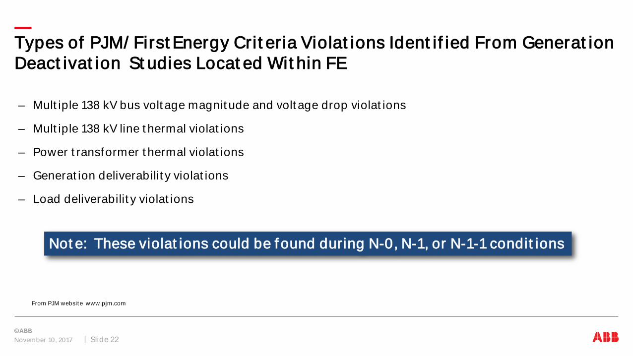
Types of PJM/ First Energy Crit eria Violat ions Ident if ied From Generat ion Deact ivat ion St udies Locat ed Wit hin FE
– Mult iple 138 kV bus volt age magnit ude and volt age drop violat ions
– Mult iple 138 kV line t hermal violat ions
– Power t ransformer t hermal violat ions
– Generat ion deliverabilit y violat ions
– Load deliverabilit y violat ions
From PJM websit e www.pjm.com
November 10, 2017 Slide 22
Not e: These violat ions could be f ound during N-0, N-1, or N-1-1 condit ions

Types of PJM/ FE RTEP Upgrade Project s From Generat ion Deact ivat ion St udies Locat ed Wit hin FE
– Conversion of ret ired generat ors t o synchronous condensers
– Inst allat ions of st at ic VAR compensat ors (SVCs)
– Inst allat ion of f ixed capacit ors
– Const ruct ion of new t ransmission lines
– Reconduct oring of exist ing t ransmission lines
– Const ruct ion of new subst at ions
– Inst allat ion or replacement of power t ransformers at exist ing subst at ions
– Expansion or reconf igurat ion of exist ing breaker subst at ions
– Upgrades in exist ing subst at ions t o relieve limit ing subst at ion t erminal equipment
From PJM websit e www.pjm.com
November 10, 2017 Slide 23

PJM RTEP Project Upgrades Driven By Baseline Upgrades Including Generat or Deact ivat ions
PJM Mid-At lant ic AreaPJM West ern Area
From PJM websit e www.pjm.com
November 10, 2017 Slide 24

November 10, 2017 Slid e 25
React ive Power
Shunt & Series Compensat ion
Reliabilit y & Transfer Capabilit y
The First Energy Experience

– Fault Level ~ syst em st rengt h
– Frequency Cont rol
– Transferring Capabilit y
– Angular st abilit y
– Volt age St abilit y
– Select ive syst em prot ect ion
– Suscept ibilit y t o harmonic dist ort ion
Im p act on Sys t em Reliab ilit y and Trans fer Cap ab ilit y
Novem b er 10 , 20 17 Slid e 26
React ive Power Compensat ion
Tradit ionally t his is provided by synchronous generat ors driven by t urbines at const ant speed.

Impact on Syst em Reliabilit y and Transfer Capabilit y
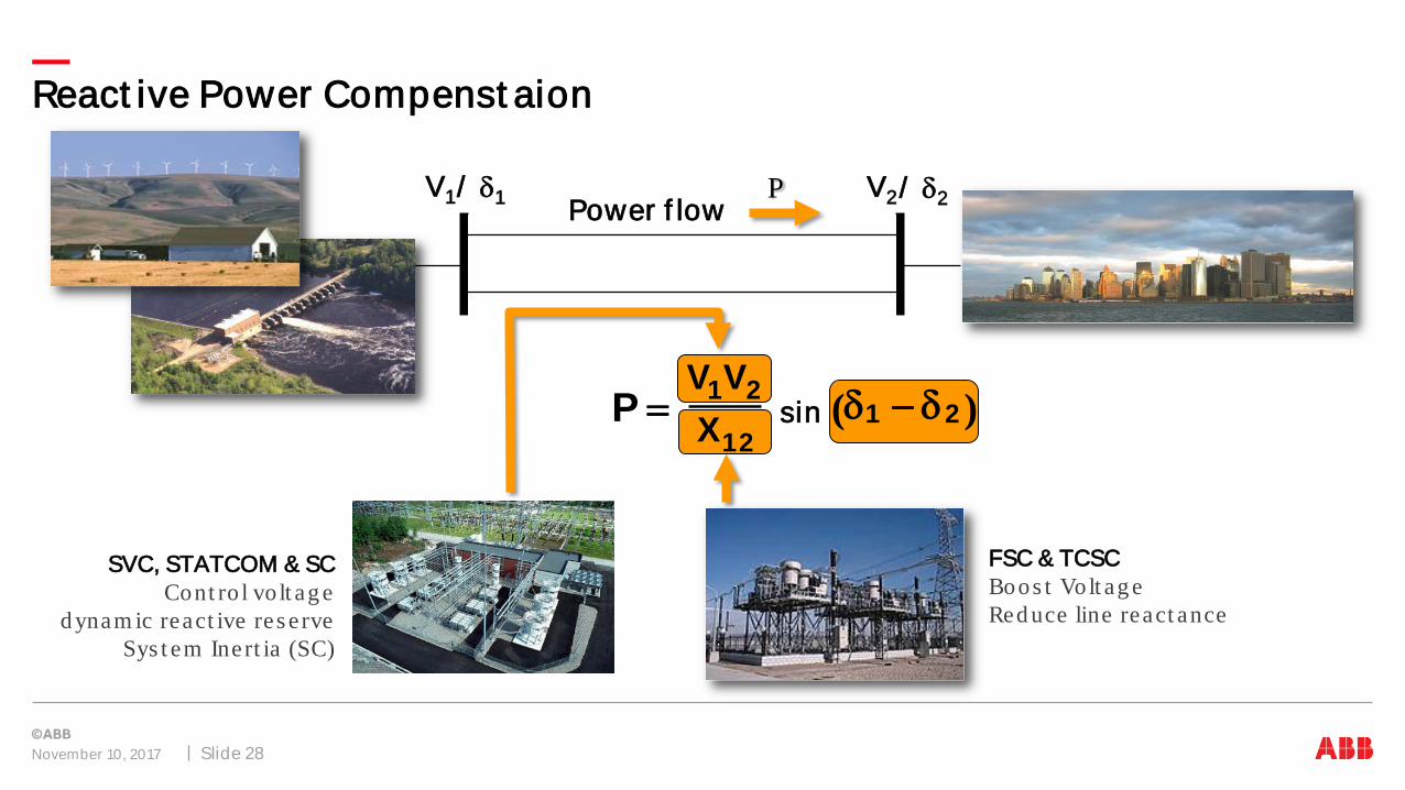
React ive Power Compenst aion
Novem b er 10 , 20 17 Slid e 27
V1/ δ1 V2/ δ2Power flowP
sin )( 2112
21X
VVP δδ −=
cos11
12XVV
Q )( 21 δδ −= 2V( − )
React ive Power Compenst aion
November 10, 2017 Slide 28
V1/ δ1 V2/ δ2Power f lowP
FSC & TCSCBoos t Volt ag eRed uce line react ance
SVC, STATCOM & SC Cont ro l vo lt ag e
d ynam ic react ive res erveSys t em Inert ia (SC)
sin )( 2112
21
XVV
P δδ −=

Dynamic or slow Vars?
Volt age Cont rol – Shunt Compensat ion
Novem b er 10 , 20 17 Slid e 29
Static Var Compensator – SVC
STATCOM
Dynamic Shunt Compensation
Synchronous Condenser

Mix of Dynamic and Slow Vars
Volt age Cont rol – Shunt Compensat ion
Novem b er 10 , 20 17 Slid e 30
MSRMSC
SC
MSRMSC´TCR TSR TSC Harmonic Filters MSRMSC
~ =
VSC Synchronous Condenser

Fixed Series Compensat ion
Series Compensat ion
Novem b er 10 , 20 17 Slid e 31

Improved Transfer capabilit y & Angular St abilit y
Series Compensat ion
Novem b er 10 , 20 17 Slid e 32

– SC and SVCs a re res ilient t o OV and UV
– STATCOM need s sp ecific d es ig n cons id era t ion fo r OV and req uires full coo ling cap ab ilit y a t LV
– Series Cap acit o rs a re d es ig ned wit h sys t em fault current in m ind .
– Series Cap acit o rs a re a llowed t o b yp as s fo r int e rna l fault s b ut m us t rem ain in op era t ion fo r ext erna l fault s
Novem b er 10 , 20 17 Slid e 34
Syst em Cont ingency Support and Ride Through
0
0.1
0.2
0.3
0.4
0.5
0.6
0.7
0.8
0.9
1.0
1.1
1.2
1.3
1.4
1.5
1.6
X.X
-1 0 1 2 Time (sec.)
Pre-fault Post-Fault Recovery
Fault Clearing
NO BLOCKING/TRIPPING AREA
TRANSIENT AREA
TSC BLOCKING LEVEL

November 10, 2017 Slid e 35
Technology Overview
The First Energy SCs and SVCs
St a t ic Var Com p ens a t o r
Synchronous Cond ens er

– SVC – Variable Shunt ad m it t ance• Vernie r Cont ro l• St ep wis e Cont ro l
– Q ~V 2
– Response t ime - order of cycles
– Const ant admit t ance at limit s
St a t ic Var Com p ens a t o r
Novem b er 10 , 20 17 Slid e 36
Technology Overview
XT
V1
V1’’
BTCR BTSC
BFLT
TCR TSC Harmonic Filter
V2
Q1
B2 = BTCR + BTSC+BFLT
X2 = 1 / B2
X1 = X2 + XT
B1 = 1 / X1
Q1 = V12 · B1
V2 = V1 · X2 / X1

• Typical volt age reference set t ing range0.9 ≤ Vref ≤ 1.1 p.u.
• Typical slope set t ing range 1 % t o 10 % @ 100 MVA base
• Low Volt age blocking level (C) ~ 0.3 p.u.• Driven by synchronizat ion
• High volt age blocking level (D) ~ 1.3 – 1.5 p.u.• Driven by TSC swit ching (if used) or syst em
volt age prof ile
St at ic Var Compensat or – Operat ional Charact erist ic
November 10, 2017 Slide 37
Technology Overview

St at ic Var Compensat or – Conf igurat ions
November 10, 2017 Slide 38
Technology Overview
´TCR TSR TSC Harmonic Filters
Static Var Compensator (SVC)
MSRMSC´TCR TSR TSC Harmonic Filters
Static Var System (SVS)

St at ic Var Compensat or – TCR
November 10, 2017 Slide 39
Technology Overview
VLL
Th1 Th2
I
Vp

St at ic Var Compensat or – TCR
November 10, 2017 Slide 40
Technology Overview
90 100 110 120 130 140 150 160 170 180-0.06
-0.05
-0.04
-0.03
-0.02
-0.01
0
0.01
0.02
0.03
Firing angle [degrees]
In/I1
n=5
n=5
n=7
n=7
n=11
n=11n=13
n=19 n=17
n=25
n=23
HV bus
TCR
Y/d
MV SVC bus
In
Filter banks

St at ic Var Compensat or – TSC
November 10, 2017 Slide 41
Technology Overview
Vc
L
Th1 Th2
I
Vp
Vp
ωt
Vc
ωt
I
ωt
FP
ωt

∆V Distributor
TCR Control
TSC Control
Vresp
Vref
Bref1ST
SlopeX
POWER SYSTEM
TCRFC TSC
Voltage Regulator
VCU
SVC Cont rol Concep t
Technology Overview
Novem b er 10 , 20 17 Slid e 42
MSRMSC
MSC/MSR Logic
Transmission Applicat ion Cont rol Concept s
– Posit ive Sequence Volt age cont rol
– Negat ive Sequence Volt age Cont rol
– Power Oscillat ion Damping (POD)

Technology Overview
November 10, 2017 Slide 43
SCSynchronous Condencer
Mechanical Power
Electrical Power
GSynchronous
Generator
MSynchronous
Motor
PEL≈ 0
Qind Qcap
PEL
Qind Qcap
Pmek
PEL
Qind Qcap
Pmek
Tmek
Tmek
Synchronous Cond ens er

Synchronous Condenser
Technology Overview
Novem b er 10 , 20 17 Slid e 44
Cap acit iveInd uct ive
– Rot at ing kinet ic Energy Provides Inert ia t o t he Syst em
– Cont ribut es t o syst em fault level
– Aut omat ic excit at ion cont rol provides Dynamic volt age support
– React ive Power Support
– No harmonic generat ion
– Subst ant ial t hermal overload capabilit y
– Capacit ive / Induct ive capabilit y ~ 2:1

Synchronous Condenser
Technology Overview
Novem b er 10 , 20 17 Slid e 45

Technology Overview
November 10, 2017 Slide 46
– Medium size machines - AC Excit ers AC Excit ers are t hree phase AC generat ors, wit h it s out put rect if ied and supplied t hrough brushes and slip rings t o t he rot or winding of t he synchronous machine.
– Large machines - Brushless Excit at ion Syst ems. A Brushless Excit er is a small AC generat or wit h it s f ield circuit on t he st at or and t he armat ure circuit on t he rot or. The t hree phase out put of t he excit er generat or is rect if ied by solid st at e rect if iers. The rect if ied out put is connect ed direct ly t o t he f ield winding and eliminat es t he use of brushes and slip rings.
Synchronous Condenser

Synchronous Condenser
Technology Overview
Novem b er 10 , 20 17 Slid e 47
∆V
Vresp
Vref Ifref
EXCITER
POWER SYSTEM
AVR
SC
Voltage Regulator
MSRMSC
MSC/ MSR Logic

November 10, 2017 Slid e 48
Technology Overview – First Energy
Green hig hlight ed devices d riven b y Genera t ion re t irem ent s

– PJM announced need for SVC in Novem b er 20 11
– +250 / -10 0 MVAR SVC connect ed t o 230 kV b us
– In-service : 20 14
– Also cont ro ls loca l 130 MVAR 230 kV m echanica lly swit ched cap acit o r
Alt oona SVC
Novem b er 10 , 20 17 Slid e 49
Technology Overview – First Energy

East lake Synchronous Condensers (SC)
Technology Overview – First Energy
Novem b er 10 , 20 17 Slid e 50
PJM announced need f or SC in April 2012
East lake 1 +124/ -80 Mvar 138 kV 5/ 27/ 2016
East lake 2 +124/ -80 Mvar 138 kV 4/ 12/ 2016
East lake 3 +124/ -80 Mvar 138 kV 6/ 1/ 2015
East lake 4 +268/ -140 Mvar 138 kV 6/ 1/ 2014
East lake 5 +560/ -206 Mvar 345 kV 5/ 26/ 2013

– PJM announced need for SVC in Ap ril 20 12
– +150 / -75 MVAR SVC connect ed t o 138 kV b us
– In-service : 20 16
– Also cont ro ls loca l 2-75 MVAR 138 kV m echanica lly swit ched cap acit o rs
Hoyt d a le SVC
Novem b er 10 , 20 17 Slid e 51
Technology Overview – First Energy

– PJM announced need for SVC in Novem b er 20 11
– +50 0 / -10 0 MVAR SVC connect ed t o 50 0 kV b us
– In-service : 20 14
– Cont ro ls loca l 110 MVAR 50 0 kV m echanica lly swit ched cap acit o r
– Com b ined -cycle g enera t ing p lant connect ed t o s am e b us
Hunt ers t own SVC
Novem b er 10 , 20 17 Slid e 52
Technology Overview – First Energy

– PJM announced need for react ive sup p ort in Ap ril 20 12
– +150 / -75 MVAR SVC connect ed t o 138 kV b us
– In-service : 20 16
– Also cont ro ls loca l 2-75 MVAR 138 kV m echanica lly swit ched cap acit o rs
Lakes hore SVC
Novem b er 10 , 20 17 Slid e 53
Technology Overview – First Energy

– PJM announced need for SVC in Novem b er 20 11
– +60 0 / -165 MVAR SVC connect ed t o 50 0 kV b us
– In-service : 20 14
– Cont ro ls loca l 20 0 MVAR 50 0 kV m echanica lly swit ched cap acit o r
Mead ow Brook SVC
Novem b er 10 , 20 17 Slid e 54
Technology Overview – First Energy

November 10, 2017 Slid e 55
Technology Overviewcont inued
STATCOM
Fixed Series Com p ens a t ion
Thyris t o r Cont ro lled Series Com p ens a t ion

– Volt age Source Convert er –act s like a variable volt age source
– Operat ion at convert er limit –VSC becomes a const ant current source
– Q ~ V
– Response t ime – sub cycle
STATCOM – Vo lt ag e Source Convert er
Novem b er 10 , 20 17 Slid e 56
Technology Overview
VSC
V’’syst
Vconv
+ VDC -
IindIcap
Vsyst
XT

STATCOM – Conf igurat ions
November 10, 2017 Slide 57
Technology Overview
STATCOM
~=
VSC
~=
VSC TSR TSC
STATCOM HYBRID
MSRMSC
~=
VSC
STATCOM SVS

• Typical volt age reference set t ing range0.9 ≤ Vref ≤ 1.1 p.u.
• Typical slope set t ing range 1 % t o 10 % @ 100 MVA base
• Low Volt age blocking level (C) ~ 0.2 p.u.• Driven by synchronizat ion
• High volt age blocking level (D) ~ 1.3 p.u.• Driven by syst em volt age prof ile or TSC
swit ching (if hybrid)• HV rat ing capt ive t o design
STATCOM – Operat ional Charact erist ic
November 10, 2017 Slide 58
Technology Overview

November 10, 2017 Slid e 59
Technology OverviewSTATCOM Hyb rid – Op era t iona l Charact eris t ic
~=
VSC TSR TSC
STATCOM HYBRID

Post Fault Behavior – why TSC/ TSR and no t MSC/ MSR ?
Novem b er 10 , 20 17 Slid e 60
Technology Overview
0.4 0.45 0.5 0.55 0.6 0.65 0.7 0.75 0.80.5
1
1.5
S1:
VR
ES
P [p
.u.]
S2:
VR
ES
P [p
.u.]
S1:F3p_NoSymBlk, S2:F3p_SymBlk
0.4 0.45 0.5 0.55 0.6 0.65 0.7 0.75 0.80
0.5
1
1.5
2
2.5
S1:
IQ_R
EF_
VR
EG
[p.u
.] S
2:IQ
_RE
F_V
RE
G [p
.u.]
0.4 0.45 0.5 0.55 0.6 0.65 0.7 0.75 0.80
0.5
1
1.5
2
2.5
3
3.5
Time [s]
S1:
Q_S
VC
[p.u
.] S
2:Q
_SV
C [p
.u.]
Voltage at PCC
IQ_REF
Q at PCC
High overvoltage due to MSC bank
TSC capacitor switched out on fault clearance

Volt age Source Convert er
November 10, 2017 Slide 61
Technology Overview
+−
Udc
+−
Udc
+−
Udc
+−
Udc
+ −U d
c+ −
U dc
+ −U d
c+ −
U dc
+− Udc
+− Udc
+− Udc
+− Udc
Ud,mVBVA

MMC VSC Swit ching Concept
Novem b er 10 , 20 17 Slid e 62
Technology Overview
−+
+
−
Udc
+
−
Udc

MMC VSC Swit ching Concept
Novem b er 10 , 20 17 Slid e 63
Technology Overview
Ud,mVBVA
Common triangle carrier, Phase B reference negated
s1 s2 s3 s4 U
0 1 0 1 0
0 1 1 0 -Ud
1 0 0 1 +Ud
1 0 1 0 0
0 0.002 0.004 0.006 0.008 0.01 0.012 0.014 0.016 0.018 0.02-1
0
1
0 0.002 0.004 0.006 0.008 0.01 0.012 0.014 0.016 0.018 0.02
0
0.5
1
Va
0 0.002 0.004 0.006 0.008 0.01 0.012 0.014 0.016 0.018 0.02
0
0.5
1
Vb
0 0.002 0.004 0.006 0.008 0.01 0.012 0.014 0.016 0.018 0.02-1
0
1
Vab

– The num b er o f vo lt ag e “s t a ircase” leve ls in t he result ing t e rm ina l vo lt ag e is 2 x N -1, N = num b er o f ce lls in s eries / p hase
– The PWM carrie r waves fo r each ce ll is int e rna lly p hase shift ed
– Low PWM swit ching freq uency for t he ind ivid ua l ce ll, in t he o rd er o f a few hund red Hz
– Effect ive swit ching freq uency is t he ce ll swit ching freq uency x N
MMC VSC Swit ching Concep t
Novem b er 10 , 20 17 Slid e 64
Technology Overview
0 0.002 0.004 0.006 0.008 0.01 0.012 0.014 0.016 0.018 0.02-2
0
2
4
6
8
10
0 0.002 0.004 0.006 0.008 0.01 0.012 0.014 0.016 0.018 0.02-1
-0.5
0
0.5
1

MMC VSC Swit ching Concept
Novem b er 10 , 20 17 Slid e 65
Technology Overview

November 10, 2017
MSC/MSR Logic
Slid e 66
Technology Overview
∆VVresp
Vref
POWER SYSTEM
Voltage control
Current control
VSC Control
DC Control
Iref
VDC
FP IP
MSRMSC
Transmission Applicat ion Cont rol Concept s
– Posit ive Sequence Volt age cont rol
– Negat ive Sequence Volt age Cont rol
– Power Oscillat ion Damping (POD)
– Act ive Filt ering
– Bat t ery Energy St orage

MMC VSC Layout
Novem b er 10 , 20 17 Slid e 67
Technology Overview

Layout Cont ainerized STATCOM
Novem b er 10 , 20 17 Slid e 68
Technology Overview
Cont ro l cab ine tAuxilia ry p ower cab ine t
UPS
Precharg erTrans form er p recharg er
Hp -filt e r
Wat er coo ling unit

– Im p rove Power Trans fer
– Im p rove Trans ient St ab ilit y
– Im p rove Volt ag e St ab ilit y
Novem b er 10 , 20 17 Slid e 69
Technology Overview – Series Compensat ion
TCSC– As for FSC
– SSR/ SSI Cont ro l
– POD
FSC

November 10, 2017 Slid e 70
Technology Overview – Series Compensat ion
Bypass DisconnectorIsolating
Disconnector Isolating Disconnector
Discharge Current Limiting Reactor
MOV
Bypass Switch (Breaker)
Platform Structure
Capacitor
Fast Protective DeviceCapThor™

Gapless FSC Design
Novem b er 10 , 20 17 Slid e 71
Technology Overview – Series Compensat ion
Bypass DisconnectorIsolating
Disconnector Isolating Disconnector
Discharge Current Limiting Reactor
MOV
Bypass Switch (Breaker)
Platform Structure
Capacitor

Two Segment FSC Design
Novem b er 10 , 20 17 Slid e 72
Technology Overview – Series Compensat ion
-QE11
-FR1
-FV1
-QS1
-Q11
-T11
-T12
-T13 -T23
-T22 -FR2
-FV2
-QS2
-T14
-C1
-T24
-C2
-Q12-QE12
-L2-L1
-T15
-Q13
-R2
-FR1
-R1
-R1
-FR1
-R1
-QS3
• Power f low requirement s• SSR Requirement s• Prot ect ion levels
• Not e t he damping circuit

TCSC
Novem b er 10 , 20 17 Slid e 73
Technology Overview – Series Compensat ion
Bypass Disconnector
Isolating Disconnector Isolating
Disconnector
TCSC Reactor MOV
Bypass Switch (Breaker)
Platform Structure
Capacitor
Thyristor Valve
TCSC breaker

TCSC for SSR mit igat ion
Novem b er 10 , 20 17 Slid e 74
Technology Overview – Series Compensat ion
15 20 25 30 35 40 45 50-14
-12
-10
-8
-6
-4
-2
0
2
4S1:Mode 5 CAP FAT, S2:Mode 5 BLK FAT
Mechanical frequency [Hz] Mechanical frequency [Hz]
Ele
ctric
al d
ampi
ng [t
orqu
e pu
/ spe
ed p
u] E
lect
rical
dam
ping
[tor
que
pu/ s
peed
pu]

Sub Synchronous Resonance
Novem b er 10 , 20 17 Slid e 75
Technology Overview – Series Compensat ion
In an Uncom pensa t ed Sys t emA fault result s in d c-offs e t com p onent s in t he m achine s t a t o r wind ing .Ba lanced fault s 60 Hz s lip a ir g ap t o rq ueUnb a lanced fault s 120 Hz s lip a ir g ap t o rq ueNo t o rs iona l m od es a llowed nea r t hese freq uencies
In a Series Com p ensa t ed Sys t emThe cap acit o r b locks t he d c-com ponentOffse t t rans ient current is an ac-current oscilla t ing wit h t he sys t em na t ura l freq uencyIn a rea l sys t em t his b ecom es m ore p ronounced t he m ore rad ia l t he ne t work b ecom esIn a s e ries com p ensa t ed sys t em t he na t ura l freq uency is sub synchronous

TCSC for Power Oscillat ion Damping (POD)
Novem b er 10 , 20 17 Slid e 76
Technology Overview
-5 0 5 10 15 20 25 30
-40
-20
0
20
xDA
MP
[oh
ms]
inductive
capacitive
bypass
min boost
max boost
switch level
-5 0 5 10 15 20 25 30
-40
-20
0
20
time [sec]
xRE
F [
ohm
s]
inductive
capacitive

TCSC for Power Oscillat ion Damping (POD)
Novem b er 10 , 20 17 Slid e 77
Technology Overview
0 500
200
400
600
800
1000
time (sec)
Plin
e (M
W)
No TCSC POD active
0 500
200
400
600
800
1000
time (sec)
Plin
e (M
W)
North TCSC POD active
0 50-40
-30
-20
-10
0
10
time (sec)
X TC
SC
0 500
200
400
600
800
1000
time (sec)
Plin
e (M
W)
Both TCSC PODs active
0 50-40
-30
-20
-10
0
10
time (sec)
X TC
SC
500 MW
trip 300 MW
Trip 30 0 MW
• 750 miles single circuit AC t ransmission int erconnect ion of Elet ronort e’s (Nort h) and Furnas’ (Sout h) 500 kV power syst ems.
• Excit at ion of 0.2 Hz Oscillat ion bet ween t he syst ems at generat ion t ripping out
• 6 FSC
• 2 TCSC
• Imperat riz: FSC 161 Mvar, TCSC 107 Mvar
• In service since 1999

Cont rol & Prot ect ion
Novem b er 10 , 20 17 Slid e 78
FACTS Technology Overview
Bypass DisconnectorIsolating
Disconnector Isolating Disconnector
Discharge Current Limiting Reactor
MOV
Bypass Switch (Breaker)
Platform Structure
Capacitor
Fast Protective DeviceCapThor™
MACH™ Control & Protection
Optic Fiber
Optic Fiber
Optic Fiber
Optic Fiber
Optic Fiber
Optic Fiber

November 10, 2017 Slid e 79
Cont rol & Prot ect ion
AC & DC Power SupplyAuxiliary Syst ems
Valve Cooling

• Main and Backup Supply• AC – supply
• Valve Cooling Pumps and Fans, • Bat t ery Chargers• Building HVAC & Light ing• Transformer Forced Cooling
• DC – supply• Cont rol Syst em• Relay Prot ect ion• 8 hours bat t ery capacit y• Main and backup syst em
Auxiliary power supply
November 10, 2017 Slide 80
Auxiliary Syst ems
ATS
Valve Cooling System Building Battery
Chargers
Preferred Supply Backup Supply

Adding a second backup supply source - g enera t o r
Novem b er 10 , 20 17 Slid e 81
Auxiliary Syst ems
ATS
Preferred Supply Backup Supply #1
Valve Cooling System Building Battery
Chargers
ATS
Backup Supply #2
G• Main and Backup Supply• AC – supply
• Valve Cooling Pumps and Fans, • Bat t ery Chargers• Building HVAC & Light ing• Transformer Forced Cooling
• DC – supply• Cont rol Syst em• Relay Prot ect ion• 8 hours bat t ery capacit y

AC Power Supply Sources
Novem b er 10 , 20 17 Slid e 82
Auxiliary Syst ems
´TCR TSC Harmonic Filters
1. SSVT at HV bus
2. Of f t he SVC/ STATCOM MV bus• Be conscious of high f ault level• Signif icant volt age variat ions• May require st abilizer
(more equipment )
3. From dist ribut ion syst em
4. Backup Source f rom exist ing St at ionService or dist ribut ion syst em
1
2
3 4

Overview
Novem b er 10 , 20 17 Slid e 83
FACTS Cont rol Syst em
Station Level
Bay Level
Process Level
Station Control
SVC Control
Main circuit, I/O, VCU
SOM PanelStation Operation & Monitoring
SVC Control & Protection Panel
• Operator workstation (HMI)• SCADA interface (GWS)• Cyber security• Remote access
• MACH™ control system hardware and software.
• Protection IEDs
VCU Panel(s)
BsysAsys
Remote Control
Customer System, SAS
Protection IEDsSVC Control and Protection, PS700
• Internal supervision• Switch-over logic• Supplementary control• Sequence control
Converter Control and Protection, PS935
• Voltage control• Flicker control• Valve protections
I/O System PS74x, PS8xx, ...
• Analog and digital I/O• MACH I/O (eTDM, EtherCAT and, CAN)• Beckhoff I/O (EtherCAT)
Valve Control Unit• Send firing data to thyristor or IGBT valve• Valve monitoring and protection
VSCLight v1
VSCLight v2, vX
TCR/TSCClassic
Valve and VCU can be seen as a intelligent primary deviceFiring data to/from IGBT, IGCT, thyristor
MACH Control System
TSR
Us
Up
TSCVSC VSC
AFS 6xxStation LAN, SuiteLink, WCF
NTSGPS-clockTime sync
OWS/SERLocal operation HMIEvent server
FTP/AVSFile transferAnti-virus
3G/4G modemIPsec VPN tunnel Remote access
RHS (option)Remote operation HMI
GWSGatewaySCADA
Main curcuit equipment
• Switchgear• Power transformer• Instrument transformer• etc
FW
Office Workstation
RDP
internet
DNP
LAN
, IEC
104,
etc
Seria
l DN
P
SMB,
file
tran
sfer
NTP, PTP
Power-up on demand. Timer for power-down.
PS700A AA
VCU
PS700A AA
PS935A AA
PS7xxA AA
PS7xxA AA
PS7xxA AA PS7xx
A AA
… or distributed IO
VCU
A AAA AA
PS935A AA
Local IO…
PS800-IO
Common IO

HMI
Novem b er 10 , 20 17 Slid e 84
FACTS Cont rol Syst em

Int egrat ed Transient Fault Recorder
Novem b er 10 , 20 17 Slid e 85
FACTS Cont rol Syst em
– Maximum lengt h 10,000 samples
– Fast response TFR
• 200 μs sampling t ime (5 kHz)
• 2 second window
– Medium response TFR
• 1 – 1000 ms sampling t ime (1 – 1000 Hz)
• 1 – 10000 second window
– Pre- and post f ault dat a
– Trigger condit ions are set f rom HMI
– All analogue and digit al signals available
– Comt rade format

Transformer
Novem b er 10 , 20 17 Slid e 86
Relay Prot ect ion
Relay Protection System A System BDifferential =T1-87-1
SEL 487E=T1-87-2GE T35
Phase Overcurrent =T1-50 / 51-1SEL 487E
=T1-50 / 51-2GE T35
Res id ua l Overcurrent =T1-50N/ 51N-1SEL 487E
=T1-50N/ 51N-2, GE F35
Neut ra l Overcurrent =T1-50G/ 51G-1SEL 487E
=T1-50G/ 51G-2GE F35
Trans form er Monit o ring Sys t em
=T1-26O, 71O, 63P, 49W, 63B, GE C30

TSC & TCR Branches
Novem b er 10 , 20 17 Slid e 87
Relay Prot et cion
Relay Protection System A System BDifferential =TSC11-87-1
=TSC12-87-1SEL 487B
=TSC11-87-2=TSC12-87-2GE B30
Phase Overcurrent =TSC11-50 / 51-1=TSC12-50 / 51-1SEL 487E
=TSC11-50 / 51-2=TSC12-50 / 51-2GE F35
Cap acit o r Unb a lance =TSC11-60 -1=TSC12-60 -1SEL 487V
=TSC11-60 -2=TSC12-60 -2GE F35

Volt age Source Convert er
Novem b er 10 , 20 17 Slid e 88
Relay Prot et cion
Relay Protection System A System B
Differential =VSC11-87-1SEL 487B
=VSC11-87-2GE B30
Phase Overcurrent =TSC11-50 / 51-1SEL 487E
=TSC11-50 / 51-2GE F35

November 10, 2017 Slid e 89
Valve Cooling Syst em
Coolant in Coolant out

Cont rol Syst em HMI pict ure
Novem b er 10 , 20 17 Slid e 90
Valve Cooling Syst em
• Closed Loop syst em • Out door heat exchangers• Deionized cooling media wit h ant if reeze
as applicable• Designed t o applicable sound
requirement s• High level of redundancy• Generally requires UMD/ UPS supply when
STATCOM

November 10, 2017 Slid e 91
Valve Cooling Syst em – Unint errupt able Power Supply

Synchronous Condenser
Novem b er 10 , 20 17 Slid e 92
Auxiliary Syst ems
Lub e Oil Skid
Cooling p um p skid Hea t Exchang er
Cont ro l & Pro t ect ionSt a rt Eq uip m ent

Series Compensat ion
Novem b er 10 , 20 17 Slid e 93
Auxiliary Syst ems

– Typ ica l Tot a l Ava ilab ilit y fo r SVC/ STATCOM Transm is s ion Ap p lica t ions ≥ 99 %
– Typ ica l Reliab ilit y ≤ 2 Forced Out ag es Per Year
– Sched uled Out ag e unava ilab ilit y roug hly 1 % for SVC and 0 .4 % for STATCOM*
– Typ ica l Tot a l ava ilab ilit y fo r FSC ≥ 99.5 % (Gap les s o r FPD) and ≥ 99 % Sp ark Gap
– Typ ica l Reliab ilit y ≤ 1 Forced Out ag e Per Year
– Sched uled Out ag e unava ilab ilit y roug hly 0 .2 % for g ap les s and 0 .4 % for Sp ark Gap
– Up g rad e Freq uency 15 – 20 years fo r Cont ro l & Pro t ect ion, Cooling
– Life t im e exp ect ancy ~ 30 yea rs
Novem b er 10 , 20 17 *Not count ing Hyb rid s , which is s im ila r t o SVCsSlid e 94
Operat ion and Maint enance