Embed Size (px)
Citation preview
TECHNICAL NOTE
Interim Recommendation for Practical Application of the CIE System for Mesopic Photometry in Outdoor Lighting
CIE TN 007:2017
CIE TN 007:2017
II CIE, All rights reserved.
CIE Technical Notes (TN) are concise technical papers summarizing information of fundamental importance to CIE Members and other stakeholders, which either have been prepared by a TC, in which case they will usually form only a part of the outputs from that TC, or through the auspices of a Reportership established for the purpose in response to a need identified by a Division or Divisions.
This Technical Note has been prepared by CIE Joint Technical Committee 1 of Division 1 “Vision and Colour”, Division 2 “Physical Measurement of Light and Radiation", Division 4 “Lighting and Signalling for Transport”, and Division 5 “Exterior Lighting and Other Applications”. The document reports on current knowledge and experience within the specific field of light and lighting described, and is intended to be used by the CIE membership and other interested parties. It should be noted, however, that the status of this document is advisory and not mandatory.
Any mention of organizations or products does not imply endorsement by the CIE. Whilst every care has been taken in the compilation of any lists, up to the time of going to press, these may not be comprehensive.
CIE 2017 - All rights reserved
CIE TN 007:2017
CIE, All rights reserved. III
The following members of JTC 1 "Implementation of CIE 191:2010 Mesopic Photometry in Outdoor Lighting" took part in the preparation of this Technical Note. The committee comes under Division 1 "Vision and Colour", Division 2 "Physical Measurement of Light and Radiation", Division 4 "Lighting and Signalling for Transport", and Division 5 "Exterior Lighting and Other Applications".
Authors:
Mucklejohn, S.A. (Chair) United Kingdom
Goodman, T.M. United Kingdom
Uchida, T. Japan
Advisor:
Donners, M. Netherlands
CIE TN 007:2017
IV CIE, All rights reserved.
CONTENTS
Summary ................................................................................................................................ 1
1 Introduction ...................................................................................................................... 1
2 Scope ............................................................................................................................... 2
3 Terms and definitions ....................................................................................................... 3
4 The adaptation field .......................................................................................................... 3
4.1 Background ............................................................................................................. 3
4.2 Adaptation field and adaptation luminance for road and street lighting applications ............................................................................................................. 5
4.3 Interpretation ........................................................................................................... 5
5 Guide for mesopic luminance calculations ........................................................................ 6
5.1 Determination of adaptation coefficient, m, and calculation of mesopic luminance ................................................................................................................ 6
5.2 Conversion between incident illuminance and road surface luminance .................... 7
6 Considerations and limitations for use of mesopic photometry in road and street lighting ............................................................................................................................. 7
7 Further work ..................................................................................................................... 9
References ............................................................................................................................. 9
CIE TN 007:2017
CIE, All rights reserved. 1
Summary
This Technical Note defines the method for calculating the adaptation coefficient to be used in conjunction with the equations of the mesopic photometry system defined in CIE 191:2010 (CIE, 2010), which describes the recommended system for mesopic photometry and is based on visual performance. This Technical Note is intended to be applicable to outdoor lighting for drivers, motorcyclists, cyclists and pedestrians. It is not applicable to other outdoor lighting, such as aviation or maritime lighting. This Technical Note provides the recommended method for calculating the spectral luminous efficiency function for mesopic vision and the associated mesopic quantities.
1 Introduction
Mesopic vision is defined as vision intermediate between photopic and scotopic vision (CIE, 2011). In mesopic vision, both the cones and rods are active; photopic vision, on the other hand, is dominated by cone activity, and in scotopic vision only the rods are active. Mesopic lighting applications are those for which our visual system is operating in a mesopic state, i.e. where both rods and cones contribute to visual functions. However, it is not straightforward to determine whether and how this condition is satisfied in any given practical s ituation. One important issue is that the range of light levels encountered in the visual environment can vary significantly, frequently extending from low mesopic to high photopic values, with the result that the adaptation condition is difficult to assess. A further complication is that the concentration of rods and cones varies throughout the retina, and most lighting applications involve a range of visual tasks which require both foveal and peripheral vision. In pure foveal
vision only the cones are active and the spectral luminous efficiency for photopic vision, V(), characterizes spectral sensitivity at all light levels (Goodman, 1997, He et al., 1997, Eloholma et al., 1998, Goodman et al., 2007, CIE 191, 2010). However, the involvement of foveal vision in a given application does not mean that only cone activity needs to be considered, as in most applications the surrounding periphery needs to be taken into account as well; in other words mesopic spectral luminous efficiency functions are frequent ly needed. The question, then, becomes: How to determine the relevant spectral weighting function? This Technical Note provides a recommendation for calculating this.
One particularly important application is road and street lighting for drivers, motorcyclists, cyclists and pedestrians, since the visual environment in night-time traffic conditions falls largely in the mesopic region. The design criteria for average road surface l uminances given
by current road lighting recommendations for various classes of roads are between 0,3 cdm−2
and 2,0 cdm−2 for motorized traffic (CIE 115, 2010). For conflict zones and pedestrian/low speed traffic, the design criteria, given in illuminance, are 2,0 lx to 50 lx (CIE 115, 2010), which are also considered to be in the mesopic range.
The recommended system for mesopic photometry describes spectral luminous efficiency for
mesopic vision, Vmes,m(),as a linear combination of the spectral luminous efficiency function
for photopic vision, V(), and the spectral luminous efficiency function for scotopic vision,
V'(), and establishes a gradual transition between these two functions throughout the
mesopic region that depends on the visual adaptation conditions. The system is of the form:
mes,1 for 0 1( ) ( ) ( ) ( ) '( )
mM m V m V m V m (1)
and
cdmes mes, e
mes, 0
( ) ( )d( )
m
m
KL V L
V
(2)
where:
m is the adaptation coefficient the value of which depends on the visual adaptation conditions;
CIE TN 007:2017
2 CIE, All rights reserved.
M(m) is a normalization factor such that Vmes,m() attains a maximum value of 1;
is the wavelength in nm;
Vmes,m() is the spectral luminous efficiency value for mesopic vision at wavelength for a given adaptation condition m;
Lmes is the mesopic luminance in cd·m-2; Kcd is the luminous efficacy for monochromatic radiation of frequency 540 × 1012 Hz as
given in the definition of the candela, which has the value 683 lm W−1;
0 is the wavelength in air corresponding to the frequency of 540 1012 Hz given in the definition of the candela, which for practical purposes can be taken as 555 nm;
Le() is the spectral radiance in W·m−2·sr−1·nm−1.
If Lmes ≥ 5,0 cdm−2, then m = 1;
if Lmes ≤ 0,005 cdm−2, then m = 0.
The above does not describe a method to determine the adaptation coefficient, m. The recommended method to determine the value of the adaptation coefficient is given in Clause 5 below.
CIE Joint Technical Committee 1 (JTC 1) was established in September 2012, with members from CIE Divisions 1, 2, 4 and 5, to give guidance on the practical implementation of CIE 191:2010 in outdoor lighting. The terms of reference were:
To investigate adaptation and viewing conditions and define visual adaptation fields in outdoor lighting;
To define lighting applications where mesopic photometry could be used;
To provide guidelines for implementing mesopic photometr y in outdoor lighting.
It soon became apparent to the members of JTC 1 that there was a pressing need to provide guidance for calculating the adaptation coefficient, m, which in turn requires definition of the size, shape and location of the appropriate adaptation field. This need was a consequence of products aimed at mesopic conditions being placed on the market.
Thus, two workgroups were set up under JTC 1 with the following terms of reference:
WG 1 – Adaptation Field
To provide a method to simulate the adaptation luminance from the luminance distribution for outdoor lighting applications. Also to provide examples of such determination of adaptation luminance for typical lighting scenes. Recommend principles for the adaptation field definition based on the adaptation luminance determination examples.
WG 2 – Simplified Method
To provide guidelines for implementing mesopic photometry in outdoor lighting, especially for street lighting and road lighting, based on knowledge current in June 2015. The guidelines will include considerations regarding definition of the size, shape and location of the adaptation field. The basis for the measurement of the luminance of the adaptation field and lighting applications where mesopic photometry could be used will be given .
This Technical Note summarizes the recommendations from WG 2.
2 Scope
This Technical Note defines the method for calculating the adaptation coefficien t, m, to be used in conjunction with the equations of the mesopic photometry system defined in CIE 191:2010. It is intended to be applicable to outdoor lighting for drivers, motorcyclists, cyclists and pedestrians. It is not applicable to other outdoor lighting, such as aviation or maritime lighting. This document also provides general guidance regarding limitations and considerations for the use of mesopic photometry for outdoor lighting.
CIE TN 007:2017
CIE, All rights reserved. 3
3 Terms and definitions
3.1 adaptation process by which the state of the visual system is modified by previous and present expo sure to stimuli that may have various luminance values, spectral distributions and angular subtenses
[SOURCE: CIE S 017:2011, term 17-18]
3.2 field of vision
extent of space in which objects are visible to an eye in a given position
[SOURCE: CIE S 017:2011, term 17-430]
3.3 S/P ratio Rsp quotient of the luminous output of a light source evaluated according to the CIE scotopic
spectral luminous efficiency function, V'(), and the luminous output evaluated according to
the CIE photopic spectral luminous efficiency function, V()
Note 1 to entry: This can be expressed by
m
0SP
m
0
( ) ( )d
( ) ( )d
K S V
R
K S V
where K′m ≈ 1 700 lm·W−1 is the maximum value of the spectral luminous efficacy for
scotopic vision, K′(), Km ≈ 683 lm·W−1 is the maximum value of the spectral luminous
efficacy for photopic vision, K(), S() is the spectral distribution of the light source,
and is the wavelength.
[SOURCE: CIE 191:2010, modified – “ratio” replaced by “quotient” , symbol adjusted]
3.4 design area
area over which the lighting is intended to provide illumination
Note 1 to entry: For the purposes of this document the design area is the horizontal area bounded by the edges of the carriageway or footpath and by transverse lines through two consecutive luminaires, as illustrated in Figure 1 in Clause 4.
3.5 mesopic enhancement factor Fmes quotient of the mesopic adaptation luminance and the photopic adaptation luminance
4 The adaptation field
4.1 Background
The 'correct' definition of the adaptation field has been a hotly-debated topic within CIE for several years. The difficulty is that the true spectral visual response function of an observer in any given situation depends on many complex factors, such as: the number, type, size and spatial distribution of sources of light within the environment (including non -static sources, such as car headlights); the direction of gaze of the observer and eye movements around this general direction; the age of the observer; and the details of the visual task being performed. These problems are not limited to mesopic photometry but are present, to a greater or lesser extent, whenever a photometric measurement is made or a photometric calculation is performed. This complexity means that simplifications and assumptions must always be made, and that the chosen spectral luminous efficiency function is only ever an approximation of the actual visual response. In particular, by definition, the spectral luminous efficiency
CIE TN 007:2017
4 CIE, All rights reserved.
function for photopic vision is always used when making measurements at photopic levels, and similarly the spectral luminous efficiency function for scotopic vision is always used when making measurements at scotopic levels. In the mesopic domain, however, such a gross simplification is not possible and the visual weighting function to be used cannot be defined without some knowledge of the visual adaptation conditions which, in turn, depend on the details of the light source(s) and the visual environment.
For mesopic photometry a different form of simplification is therefore necessary. Rather than defining the weighting function, the approach is to define the visual environment. Clearly, the same environment will not be suitable for all applications, but it is possible to make a definition of the conditions that should be used for specific cases. For the purposes of this Technical Note, which is for outdoor lighting for drivers, cyclists and pedestrian s, the main objective of mesopic photometry is either to aid in the selection of the ‘best’ (generally the most energy efficient) light source at the design stage of an installation or to validate (through measurement) the performance of an installation against the original design objectives. Recent studies regarding the adaptation state show that the local luminance around the point of observation is the primary determinant of the adaptation state, even though the surrounding luminance also has marginal effects (Uchida and Ohno, 2014, Cengiz et al., 2015). It is therefore reasonable for these purposes to define the adaptation field to be the same as the evaluation area used in the design specification for the installation and to select the relevant spectral luminous efficiency function on the basis of the average luminance of this adaption field. Because of these reasons, this Technical Note recommends using the average luminance in the design area as the adaptation luminance for relevant mesopic calculation s.
In some cases, it may be required to determine mesopic quantities for regions outside the design area, e.g. to assess compliance with recommended lighting levels for visual task performance in peripheral areas of the visual field. In many such situations, particularly in non-urban areas, the luminance of regions outside of the design area is considerably lower than that inside this area. In this case, using the adaptation field as defined in this Technical Note gives an adaptation luminance that is higher than that which would be obtained by taking an average luminance over the whole of the visual field , which in turn means that the value of the adaptation coefficient is lower than it would be if a larger adaptation field was used. Hence, the true degree of the mesopic effect for peripheral tasks in this situation will be under-estimated. In situations where substantial amounts of additional ambient lighting are present, such as provided by billboards and shop windows in town centres, this additio nal spill light will tend to increase the actual road surface luminance from the design value. Thus in this situation, although the defined adaptation field may yield a slight overestimate of the degree of mesopic enhancement compared with that obtained us ing a larger adaptation field, this will be compensated for in practice by the additional light present on the road surface. In both cases, using the simple definition of the adaptation field given in this Technical Note will result in luminance levels for the final installation that err somewhat on the side of caution and may therefore represent a reasonable compromise between ‘truth’ and ‘utility’. It is therefore recommended that the average luminance of the design area may be used as (an approximation of) the adaptation luminance in those circumstances where mesopic photometry is considered applicable for evaluating the suitability of a road lighting installation for peripheral visual task performance.
As an example of how to determine the design area to be used, CIE 140-2000 states: 'The field of calculation should be typical of the area of the road which is of interest to the driver. In the longitudinal direction on a straight road, the field of calculation should lie between two luminaires in the same row, the first luminaire being located 60 m ahead of the observer. In the transverse direction, it should cover the whole carriageway width on roads without a central reservation, and the width of one carriageway on roads with a central reservation.' This same definition should therefore be used for any lighting installation designed to achieve a specified level of performance using the method of calculation given CIE 140 -2000.
In practice, since an important element of any road lighting design is always th at it should be ‘uniform’ to within specified limits, the precise size, shape and location of the measured area within this defined region is not critical. Thus when making measurements it is not necessary for the field of view of the measuring instrument to match precisely the defined adaptation field. However, it should not be larger than the adaptation field (since this would potentially
CIE TN 007:2017
CIE, All rights reserved. 5
include areas of different and/or non-uniform luminance), nor should it be substantially smaller (since this could make the results unduly sensitive to small areas of non-uniformity in the road surface, for example). Furthermore, although (by design) any non -uniformities within the defined adaptation field should be small, these should still be analysed and allowed for when evaluating the uncertainty associated with the measured adaptation luminance.
Other definitions of the adaptation field may be more appropriate for other applications (e.g. emergency lighting for safe evacuation of buildings) but these are outside of th e scope of this Technical Note.
4.2 Adaptation field and adaptation luminance for road and street lighting applications
For the purposes of mesopic photometry for road and street lighting for drivers, motorcyclists, cyclists and pedestrians, the adaptation field is taken as the design area, i.e. the area over which the lighting is intended to provide illumination at a specified luminance or illuminance level. The adaptation luminance is taken as the average luminance of the adaptation field.
NOTE 1 It is implicit in this definition that the variations in luminance within the adaptation field are small, since all lighting design specifications require good uniformity.
NOTE 2 Mesopic photometry is not appropriate for all road lighting applications. Clause 6 outlines points to be considered when deciding whether the system of mesopic photometry should be used.
4.3 Interpretation
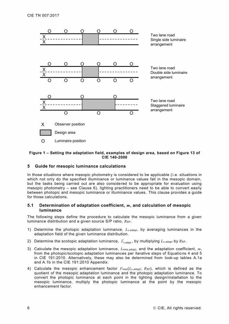
As stated in 4.2, for the purposes of this Technical Note the adaptation luminance is defined as the average luminance measured over the design area (often called the field of calculation) given in the relevant specification document or in a supplementary document such as CIE 140-2000. In the case where measurements are made in-situ, the area selected for the measurements should be typical of the road surface (e.g. areas including repaired potholes should be avoided). Since the reflectance characteristics of the road surface are generally not completely Lambertian, the direction of measurement may influence the results. The luminance measurements should therefore be made in a direction that is representative of the direction of view for a typical observer. This direction may be specified in the relevant specification document or as described in a supplementary document such as CIE 140-2000. Figure 1 shows examples of the adaptation field, which are specified as the fields of calculation in CIE 140-2000.
CIE TN 007:2017
6 CIE, All rights reserved.
Figure 1 – Setting the adaptation field, examples of design area, based on Figure 13 of CIE 140-2000
5 Guide for mesopic luminance calculations
In those situations where mesopic photometry is considered to be applicable ( i.e. situations in which not only do the specified illuminance or luminance values fall in the mesopic domain, but the tasks being carried out are also considered to be appropriate for evaluation using mesopic photometry – see Clause 6), lighting practitioners need to be able to convert easily between photopic and mesopic luminance or illuminance values. This clause provides a guide for those calculations.
5.1 Determination of adaptation coefficient, m, and calculation of mesopic luminance
The following steps define the procedure to calculate the mesopic luminance from a given luminance distribution and a given source S/P ratio, RSP.
1) Determine the photopic adaptation luminance, Lv,adapt, by averaging luminances in the adaptation field of the given luminance distribution.
2) Determine the scotopic adaptation luminance, v,adapt'L , by multiplying Lv,adapt by RSP.
3) Calculate the mesopic adaptation luminance, Lmes,adapt, and the adaptation coefficient, m, from the photopic/scotopic adaptation luminances per iterative steps of Equatio ns 4 and 5 in CIE 191:2010. Alternatively, these may also be determined from look-up tables A.1a and A.1b in the CIE 191:2010 Appendix.
4) Calculate the mesopic enhancement factor Fmes(Lv,adapt; RSP), which is defined as the
quotient of the mesopic adaptation luminance and the photopic adaptation luminance. To convert the photopic luminance at each point in the lighting design/installation to the mesopic luminance, multiply the photopic luminance at the point by the mesopic enhancement factor.
O
Observer position
Design area
Luminaire position
X
XX
OOO O OOTwo lane road
Single side luminaire
arrangement
Two lane road
Double side luminaire
arrangement
XX
OOO O OO
OOO O OO
Two lane road
Staggered luminaire
arrangement
XX
O OO
OOO
CIE TN 007:2017
CIE, All rights reserved. 7
Example: For a photopic luminance of 0,300 cd·m−2 and an S/P ratio of 1,80, Table A.1a of CIE 191:2010 gives m = 0,614.
For these values Table A.1b of CIE 191:2010 gives a mesopic luminance for the adaptation field of 0,348 cd·m−2. This same value of m may be used when calculating the mesopic luminance of regions outside of the adaptation
field but within the observer’s field of view. If the S/P ratio of the light source was changed, e.g. to 2,50, whilst maintaining the same average photopic luminance of 0,300 cd·m−2 within the adaptation field, the corresponding value of m would be 0,629 and the
mesopic luminance would be 0,386 cd·m−2.
It should be noted that for the purposes of these calculations the S/P ratio of the adaptation field is taken to be the same as that of the light source being used. In reality the adaptation conditions will also be affected by other factors that impact on the spectral distribution of the light entering an observer’s eye, particularly the spectral reflectance characteristics of the road surface (e.g. asphalt, concrete, cobblestone and red brick all have different spectral reflectance). Using the S/P ratio of the light source is a simplification but also leads to potential error in the calculated values. If better information is available, via direct measurement of the average spectral power distribution of the adaptation field for example, then this should be used for calculation of the adaptation coefficient and associated mesopic quantities.
5.2 Conversion between incident illuminance and road surface luminance
Many road lighting standards and recommendations are given in terms of incident illuminance such as those found in CIE 115:2010. Also, many photometric measurements include only values for illuminance. However, the calculations in 5.1 above require luminances.
For the calculation steps in 5.1, the road surface luminance coefficient (see CIE 066-1984 and CIE 144:2001) may be used to determine the corresponding road surface luminance1. This coefficient is generally not known, but for the purposes of the design of road lighting installations a standard road surface luminance coefficient can be used, q0 = 0,0700 sr−1.
Example:
For the examples given in 5.1, the photopic illuminance would be 0,300 cd·m−2/0,0700 sr−1 = 4,29 lx. Conversely, if the photopic illuminance is specified as, say 5,00 lx, the corresponding photopic luminance (using q0 =
0,0700 sr−1) is 0,35 cd·m−2.
The actual road surface luminance coefficient depends on a number of parameters, including the road surface material, road surface condition (e.g. wet or dry), observing direction, and the position of the installed luminaires. If a value is available that is more applicable for the situation under consideration than the standard value, this should be used for the conversion between mesopic illuminance and luminance quantities.
6 Considerations and limitations for use of mesopic photometry in road and street lighting
Although applications or tasks where mesopic photometry can be applied are still under consideration in CIE JTC 1, some common understanding can be found in CIE 191 (CIE, 2010), CIE 206 (CIE, 2014) and other publications. This clause provides a short summary of tasks which are considered to be suitable/unsuitable for assessment using mesopic photometry, based on currently available information.
As is made clear in CIE 191 (CIE, 2010) the CIE system for mesopic photometry is only relevant for peripheral task performance; it is not applicable to foveal vision. For foveal tasks, the luminous efficiency function for photopic vision should be used at all lighting levels. The following are examples of such foveal tasks:
reading road signs;
recognizing facial expressions and features (CIE, 2014; Yang and Fotios, 2015);
1 The general equation for calculating the luminance of a diffusely reflecting surface from the incident illuminance
is L = ρ E / π where L is the luminance, E is the illuminance and ρ is the reflectance of the surface in question.
Note that the equation strictly holds only for an isotropically reflecting diffuser.
CIE TN 007:2017
8 CIE, All rights reserved.
on-axis object detection (He et al., 1997).
NOTE For drivers in high-speed traffic, a pedestrian standing at the side of the road is also considered to be an on-axis target (Gibbons et al., 2016).
On the other hand, tasks that primarily involve peripheral vision are generally suitable for evaluation using mesopic photometry. Additionally, the CIE system for mesopic photometry has been shown to be well-correlated with spatial brightness (CIE, 2014) and can therefore also be used for tasks where brightness perception is important. Example tasks where mesopic photometry can be applied include the following (further examples are given in CIE 191 (CIE, 2010):
spatial brightness (CIE, 2014; Fotios and Cheal, 2011);
peripheral object detection, such as raised paving slab for pedestrian (CIE, 2014 ; Fotios and Cheal, 2013) and roadside moving target for drivers in low-speed traffic (Akashi et al., 2007).
As explained previously, the adaptation field defined in 4.2 has been selected as representing a reasonable compromise between truth and utility. It is not intended to represent the actual state of visual adaptation, but instead (for the applications considered in this Technical Note) serves primarily to facilitate the comparison of, and selection between, different types of light source in a given installation at the design stage, particularly in terms of the need to reduce energy consumption whilst maintaining safe and effective light levels. In general, using the adaption field as defined in this Technical Note will lead to either:
a) an overestimate of the adaptation luminance and hence an underestimate of the potential reduction in photopic luminance that could be achieved by using mesopically enhanced lighting (in situations where the surround area is of a lower luminance than the adaptation field); or
b) an underestimate of the actual luminance of the road surface in the final installation (in those situations where the influence of light sources outside of the defined adaptation field cannot be known or allowed for at the design stage).
In both cases, the approach used in this Technical Note tends to err on the side of caution by ensuring that the luminance of the final installation will be equal to, or higher than, the level that could potentially be justified through the use of mesopically enhanced lighting in those circumstances where mesopic photometry is considered applicable.
Recent results from several investigations using luminance cameras and eye tracking have shown that a driver in an urban environment is, in practice, photopically adapted. Also, in rural areas, headlights of oncoming cars will disrupt the driver's mesopic adaptation. A more detailed consideration of these factors will be described in a Technical Report (in preparation by JTC 1).
When choosing the most appropriate light source in any given situation, i t is important to remember that the mesopic luminous efficacy is not the only consideration; the choi ce of light source spectrum should also take account of other aspects that may be critical for the specific application, such as:
colour recognition;
colour rendering;
discomfort glare, especially for elderly people;
attention and alertness;
acceptability to users;
sky glow;
effects on the natural environment, including impacts on flora and fauna ;
human health and well-being.
CIE TN 007:2017
CIE, All rights reserved. 9
If specifications or recommendations for source spectrum, correlated colour temperature, colour rendering or chromaticity are given, they should be respected (including any recommendations relating to colour uniformity within the visual field). Further information on the selection of the source spectrum for pedestrian lighting can be found in CIE 206 (CIE, 2014).
7 Further work
The members of JTC 1 are continuing to research the relationship between the photopic luminance distribution within the observer’s visual field and the mesopic adaptation. For example, a simulation method, taking into account luminance distribution, eye movement of the observer, the surrounding luminance effect and the area of measurement, has been proposed to determine adaptation luminance for implementation of the CIE system for mesopic photometry (Uchida et al., 2016).
The analyses of the new experimental investigations may lead to a change in the recommendation of the size, shape and location of the adaptation field. In this case, this Technical Note will either be revised or withdrawn and replaced by the new recommendation.
References
AKASHI, Y., REA, M.S., BULLOUGH, J.D. 2007. Driver decision making in response to peripheral moving targets under mesopic light levels. Lighting Res. & Tech.39, 53-67.
CENGIZ, C., MAKSIMAINEN, M., PUOLAKKA, M., HALONEN, L. 2016. Contrast threshold measurements of peripheral targets in night-time driving images. Lighting Res. & Tech. 48, 491-501. (doi:10.1177/1477153515578308)
CIE 066:1984 Road Surfaces and Lighting. (ISBN 978-3-901906-72-5)
CIE 140-2000 Road Lighting Calculations. (ISBN 978-3-901906-54-1)
CIE 144:2001 Road Surface and Road Marking Reflection Characteristics . (ISBN 978-3-901906-12-1)
CIE 115:2010 (2nd edition) Lighting of Roads for Motor and Pedestrian Traffic . (ISBN 978-3-901906-86-2)
CIE 191:2010 Recommended System for Mesopic Photometry Based on Visual Performance . (ISBN 978-3-901906-88-6)
CIE S 017/E:2011 ILV: International Lighting Vocabulary .
CIE 206:2014 The Effect of Spectral Power Distribution on Lighting for Urban and Pedestrian Areas. (ISBN 978-3-902842-33-6)
ELOHOLMA, M., HALONEN, L., SETÄLÄ, K. 1998. The Effects of Light Spectrum on Visual Acuity in Mesopic Lighting Levels. Proc EPRI/LRO Fourth International Lighting Research Symposium, pp.149-161.
FOTIOS, S.A., CHEAL, C. 2011. Predicting lamp spectrum effects at mesopic levels. Part 1: Spatial brightness. Lighting Res. & Tech. 43, 143-157. (doi: 10.1177/1477153510393932)
FOTIOS, S., CHEAL, C. 2013.Using obstacle detection to identify appropriate illuminances for lighting in residential roads. Lighting Res. & Tech. 45, 362-376 (doi: 10.1177/1477153512444112)
GIBBONS, R. B., TERRY, T., BHAGAVATHULA, R., MEYER, J., LEWIS, A. 2016. Applicability of mesopic factors to the driving task. Lighting Res. & Tech. 48, 70-82.
GOODMAN, T. 1997. Workshop – Making measurements in the mesopic region. Proceedings of the NPL-CIE-UK Conference Visual Scales; Photometric and Colorimetric Aspects . Vienna: CIE Central Bureau.
GOODMAN, T., FORBES, A., WALKEY, H., ELOHOLMA, M., HALONEN, L., ALFERDINCK, J., FREIDING, A., BODROG,I P., VÁRADY, G., SZALMAS, A. 2007. Mesopic visual
CIE TN 007:2017
10 CIE, All rights reserved.
efficiency IV: A model with relevance to night-time driving and other applications. Lighting Res. & Tech. 39, 365-392.
HE, Y., REA, M., BIERMAN, A., BULLOUGH, J. 1997. Evaluating light source efficacy under mesopic conditions using reaction times. J. Illumin. Eng. Soc. 26, 125-138.
UCHIDA, T., OHNO, Y. 2014. Defining the visual adaptation field for mesopic photometry: Does surrounding luminance affect peripheral adaptation? Lighting Res. & Tech. 46, 520-533.
UCHIDA, T., AYAMA, M., AKASHI Y., HARA, N., KITANO, T., KODAIRA, Y., SAKAI, K. 2016. Adaptation luminance simulation for CIE mesopic photometry system implementation. Lighting Res. & Tech. 48, 14-25. (doi:10.1177/1477153515626210)
YANG, B., FOTIOS, S. 2015. Lighting and recognition of emotion conveyed by facial expressions. Lighting Res. & Tech. 47, 964-975. (doi: 10.1177/1477153514547753)