Embed Size (px)
Citation preview
CiB Initial Walkthrough Guide
October 2014 Rev (V1.2)
Supermicro Storage Group
Supermicro CiB
Windows® Server 2012 R2 on Supermicro Cluster-in-a-Box Walkthrough Guide
Summary
This document is designed to allow the user to initially setup and configure the Supermicro CiB product.
The system is delivered with the software pre-installed and all that remains is for the user to integrate
the system into their own environment.
Scope
This document is specifically aimed at installing and configuring the Supermicro CiB system. It does not
cover Administrative details such as setting up DHCP servers, Domain and Active Directory configuration
and assigning user permissions. Please refer to the appropriate Microsoft ® documentation for this
information.
Best practices and tips are highlighted in bold text with a “note icon” throughout the document!
Helpful information about setting up a Microsoft Cluster can be found here at
http://technet.microsoft.com/en-us/library/hh831579.aspx

Disclaimer
The intent of this document is to provide a quick start guide for the user deploying the Supermicro CiB
product. The appropriate software vendor should be treated as the definitive resource for
Software/Operating System setup. Information contained herein is provided with the best intent,
however Supermicro cannot be held responsible for errors or omissions contained in this document.
Feedback is greatly encouraged.
All Trademarks respected and acknowledged.

Contents 1. Cluster Setup Walkthrough ..........................................................................................................1
Network cabling..............................................................................................................................1
First Boot .......................................................................................................................................1
2. APPENDIX – Troubleshooting ..................................................................................................... 13
Figures
Figure 1 Connecting the heartbeat cable ..............................................................................................1
Figure 2 Initial screen ..........................................................................................................................2
Figure 3 Entering the Product Key........................................................................................................2
Figure 4 Accepting the License Terms ..................................................................................................3
Figure 5 Performing Initial Configuration Tasks.....................................................................................4
Figure 6 Setting the IP Addresses .........................................................................................................4
Figure 7 Connecting the DHCP cables ...................................................................................................5
Figure 8 Setting the Cluster Name and Domain.....................................................................................5
Figure 9 Issuing Domain Credentials ....................................................................................................6
Figure 10 Completing the Domain and Cluster Settings .........................................................................7
Figure 11 Restarting the System ..........................................................................................................8
Figure 12 Provisioning Storage ............................................................................................................9
Figure 13 Validating the Cluster ...........................................................................................................9
Figure 14 Selecting the Validation Nodes .............................................................................................9
Figure 15 Completing the Cluster Validation....................................................................................... 10
Figure 16 Final Cluster Validation screen ............................................................................................ 11
Figure 17 Checking that the cluster has been deployed ....................................................................... 12
Figure 18 Verifying cluster connection ............................................................................................... 12
Figure 19 Domain Name Issues .......................................................................................................... 14
Figure 20 Quorum issues ................................................................................................................... 15
Figure 21 Node communication error ................................................................................................ 16
Figure 22 Node communication error workaround screen 1 ................................................................ 17
Figure 23 Node communication error workaround screen 2 ................................................................ 17
Figure 24 Node communication error workaround screen 3 ................................................................ 18
Figure 25 Node communication error workaround screen 4 ................................................................ 18
Figure 26 Node communication error workaround screen 5 ................................................................ 18
Windows Server 2012 R2 on Supermicro Cluster - in-a-Box Walkthrough Guide
1
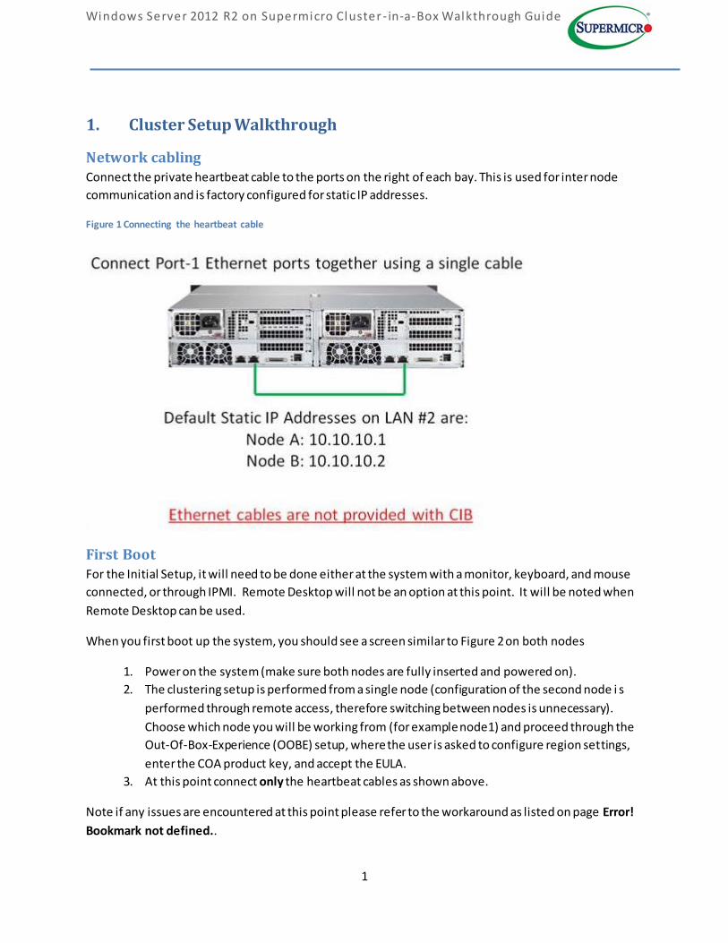
1. Cluster Setup Walkthrough
Network cabling Connect the private heartbeat cable to the ports on the right of each bay. This is used for inter node
communication and is factory configured for static IP addresses.
Figure 1 Connecting the heartbeat cable
First Boot For the Initial Setup, it will need to be done either at the system with a monitor, keyboard, and mouse
connected, or through IPMI. Remote Desktop will not be an option at this point. It will be noted when
Remote Desktop can be used.
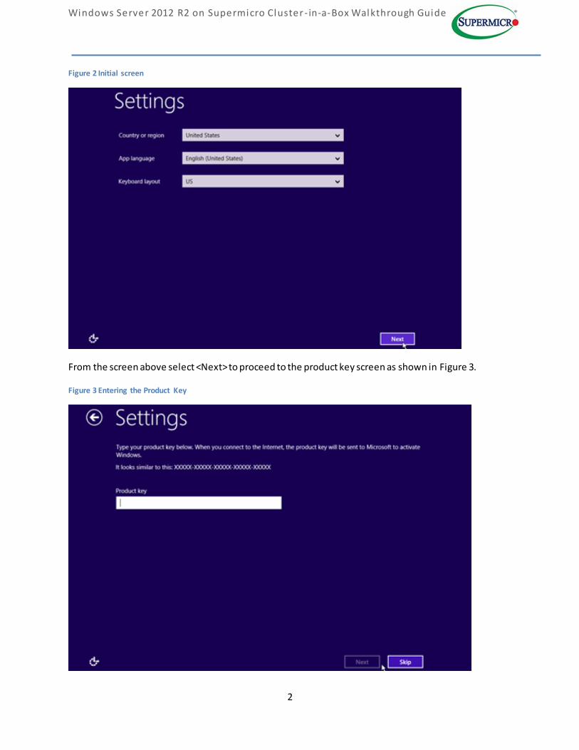
When you first boot up the system, you should see a screen similar to Figure 2 on both nodes
1. Power on the system (make sure both nodes are fully inserted and powered on).
2. The clustering setup is performed from a single node (configuration of the second node i s
performed through remote access, therefore switching between nodes is unnecessary).
Choose which node you will be working from (for example node1) and proceed through the
Out-Of-Box-Experience (OOBE) setup, where the user is asked to configure region settings,
enter the COA product key, and accept the EULA.
3. At this point connect only the heartbeat cables as shown above.
Note if any issues are encountered at this point please refer to the workaround as listed on page Error!
Bookmark not defined..
Windows Server 2012 R2 on Supermicro Cluster - in-a-Box Walkthrough Guide
2
Figure 2 Initial screen
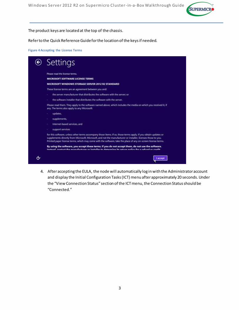
From the screen above select <Next> to proceed to the product key screen as shown in Figure 3.
Figure 3 Entering the Product Key
Windows Server 2012 R2 on Supermicro Cluster - in-a-Box Walkthrough Guide
3
The product keys are located at the top of the chassis.
Refer to the Quick Reference Guide for the location of the keys if needed.
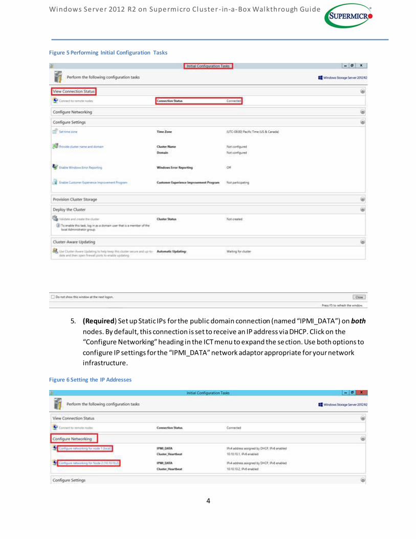
Figure 4 Accepting the License Terms
4. After accepting the EULA, the node will automatically log in with the Administrator account
and display the Initial Configuration Tasks (ICT) menu after approximately 20 seconds. Under
the “View Connection Status” section of the ICT menu, the Connection Status should be
“Connected.”
Windows Server 2012 R2 on Supermicro Cluster - in-a-Box Walkthrough Guide
4
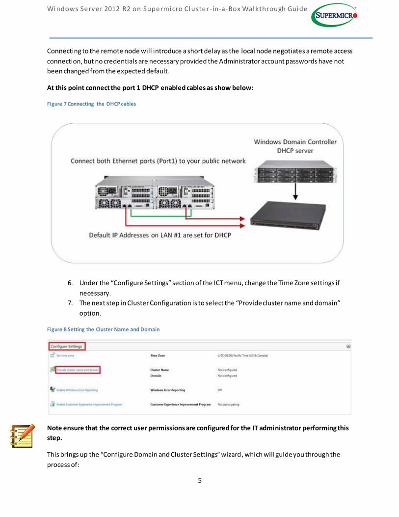
Figure 5 Performing Initial Configuration Tasks
5. (Required) Set up Static IPs for the public domain connection (named “IPMI_DATA”) on both
nodes. By default, this connection is set to receive an IP address via DHCP. Click on the
“Configure Networking” heading in the ICT menu to expand the section. Use both options to
configure IP settings for the “IPMI_DATA” network adaptor appropriate for your network
infrastructure.
Figure 6 Setting the IP Addresses
Windows Server 2012 R2 on Supermicro Cluster - in-a-Box Walkthrough Guide
5
Connecting to the remote node will introduce a short delay as the local node negotiates a remote access
connection, but no credentials are necessary provided the Administrator account passwords have not
been changed from the expected default.
At this point connect the port 1 DHCP enabled cables as show below:
Figure 7 Connecting the DHCP cables
6. Under the “Configure Settings” section of the ICT menu, change the Time Zone settings if
necessary.
7. The next step in Cluster Configuration is to select the “Provide cluster name and domain”
option.
Figure 8 Setting the Cluster Name and Domain
Note ensure that the correct user permissions are configured for the IT administrator performing this
step.
This brings up the “Configure Domain and Cluster Settings” wizard , which will guide you through the
process of:
Windows Server 2012 R2 on Supermicro Cluster - in-a-Box Walkthrough Guide
6
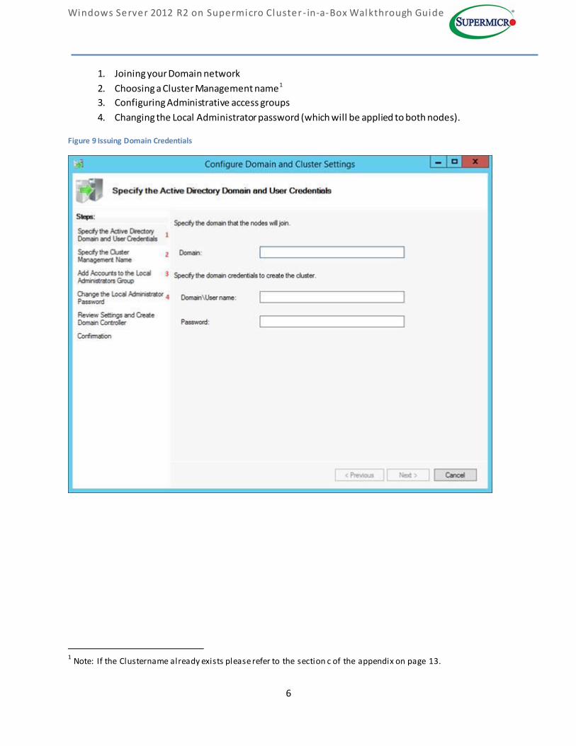
1. Joining your Domain network
2. Choosing a Cluster Management name1
3. Configuring Administrative access groups
4. Changing the Local Administrator password (which will be applied to both nodes).
Figure 9 Issuing Domain Credentials
1 Note: If the Clustername already exists please refer to the section c of the appendix on page 13.
Windows Server 2012 R2 on Supermicro Cluster - in-a-Box Walkthrough Guide
7
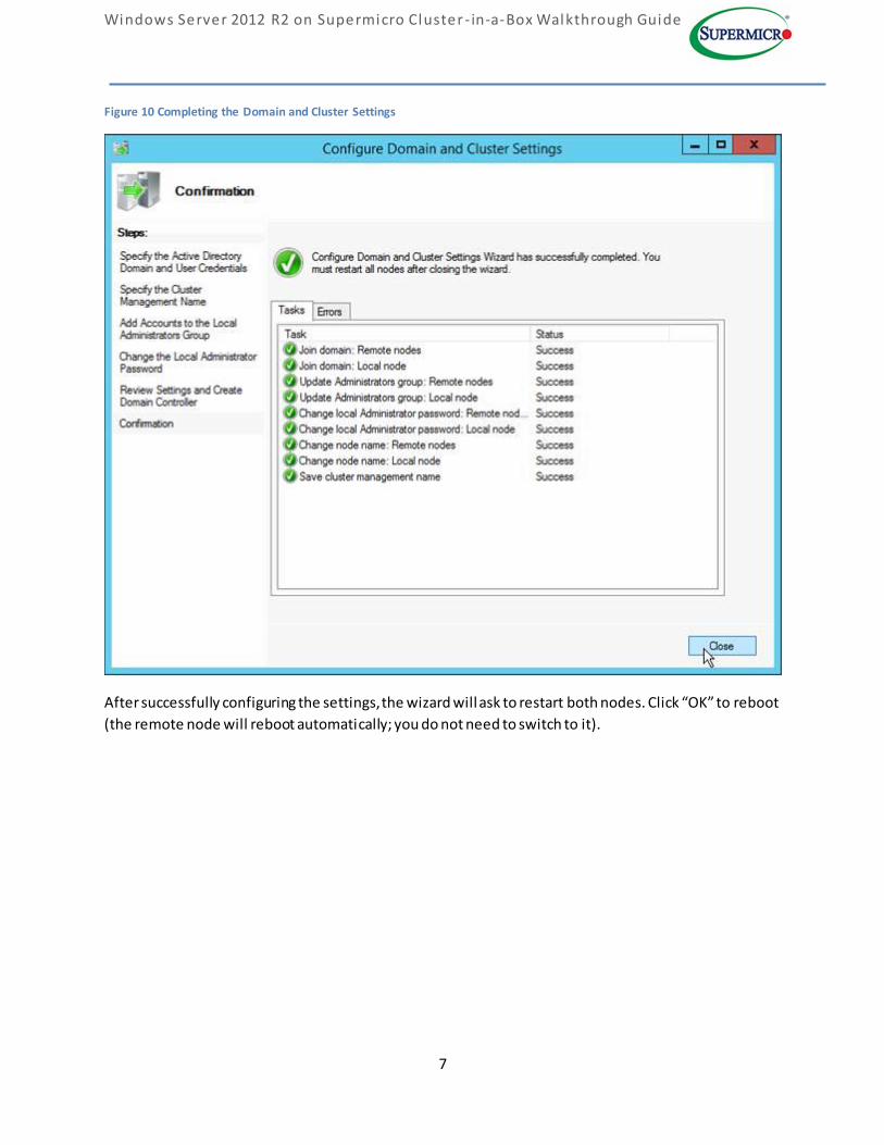
Figure 10 Completing the Domain and Cluster Settings
After successfully configuring the settings, the wizard will ask to restart both nodes. Click “OK” to reboot
(the remote node will reboot automatically; you do not need to switch to it).
Windows Server 2012 R2 on Supermicro Cluster - in-a-Box Walkthrough Guide
8
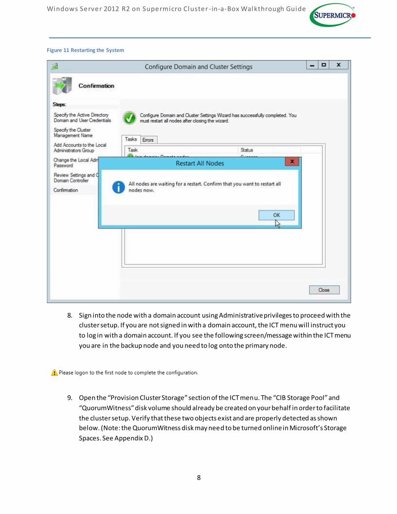
Figure 11 Restarting the System
8. Sign into the node with a domain account using Administrative privileges to proceed with the
cluster setup. If you are not signed in with a domain account, the ICT menu will instruct you
to log in with a domain account. If you see the following screen/message within the ICT menu
you are in the backup node and you need to log onto the primary node.
9. Open the “Provision Cluster Storage” section of the ICT menu. The “CIB Storage Pool” and
“QuorumWitness” disk volume should already be created on your behalf in order to facilitate
the cluster setup. Verify that these two objects exist and are properly detected as shown
below. (Note: the QuorumWitness disk may need to be turned online in Microsoft’s Storage
Spaces. See Appendix D.)
Windows Server 2012 R2 on Supermicro Cluster - in-a-Box Walkthrough Guide
9
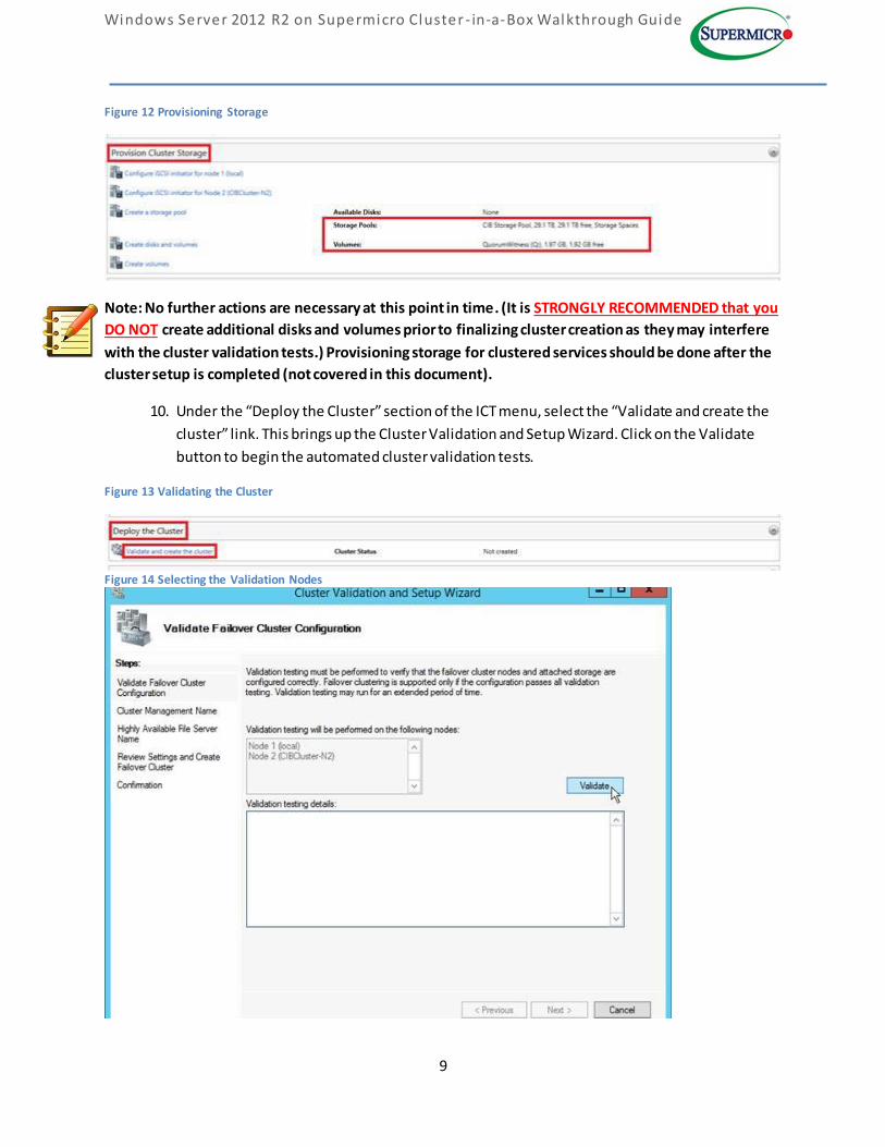
Figure 12 Provisioning Storage
Note: No further actions are necessary at this point in time. (It is STRONGLY RECOMMENDED that you
DO NOT create additional disks and volumes prior to finalizing cluster creation as they may interfere
with the cluster validation tests.) Provisioning storage for clustered services should be done after the
cluster setup is completed (not covered in this document).
10. Under the “Deploy the Cluster” section of the ICT menu, select the “Validate and create the
cluster” link. This brings up the Cluster Validation and Setup Wizard. Click on the Validate
button to begin the automated cluster validation tests.
Figure 13 Validating the Cluster
Figure 14 Selecting the Validation Nodes
Windows Server 2012 R2 on Supermicro Cluster - in-a-Box Walkthrough Guide
10
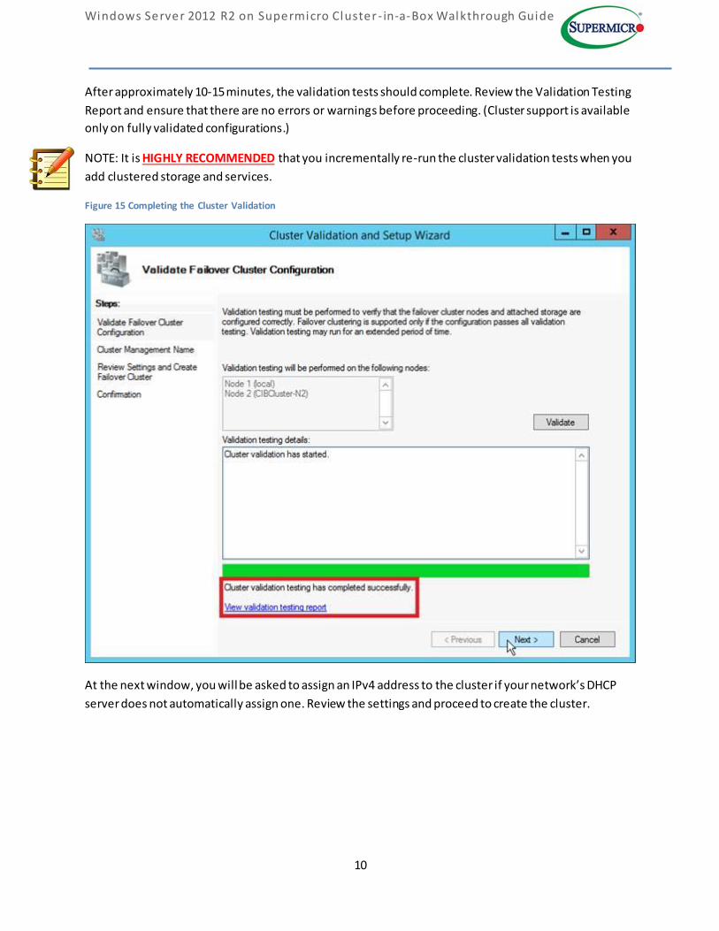
After approximately 10-15 minutes, the validation tests should complete. Review the Validation Testing
Report and ensure that there are no errors or warnings before proceeding. (Cluster support is available
only on fully validated configurations.)
NOTE: It is HIGHLY RECOMMENDED that you incrementally re-run the cluster validation tests when you
add clustered storage and services.
Figure 15 Completing the Cluster Validation
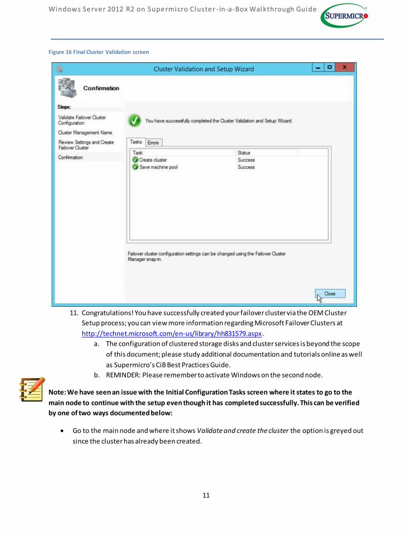
At the next window, you will be asked to assign an IPv4 address to the cluster if your network’s DHCP
server does not automatically assign one. Review the settings and proceed to create the cluster.
Windows Server 2012 R2 on Supermicro Cluster - in-a-Box Walkthrough Guide
11
Figure 16 Final Cluster Validation screen
11. Congratulations! You have successfully created your failover cluster via the OEM Cluster
Setup process; you can view more information regarding Microsoft Failover Clusters at
http://technet.microsoft.com/en-us/library/hh831579.aspx.
a. The configuration of clustered storage disks and cluster services is beyond the scope
of this document; please study additional documentation and tutorials online as well
as Supermicro’s CiB Best Practices Guide.
b. REMINDER: Please remember to activate Windows on the second node.
Note: We have seen an issue with the Initial Configuration Tasks screen where it states to go to the
main node to continue with the setup even though it has completed successfully. This can be verified
by one of two ways documented below:
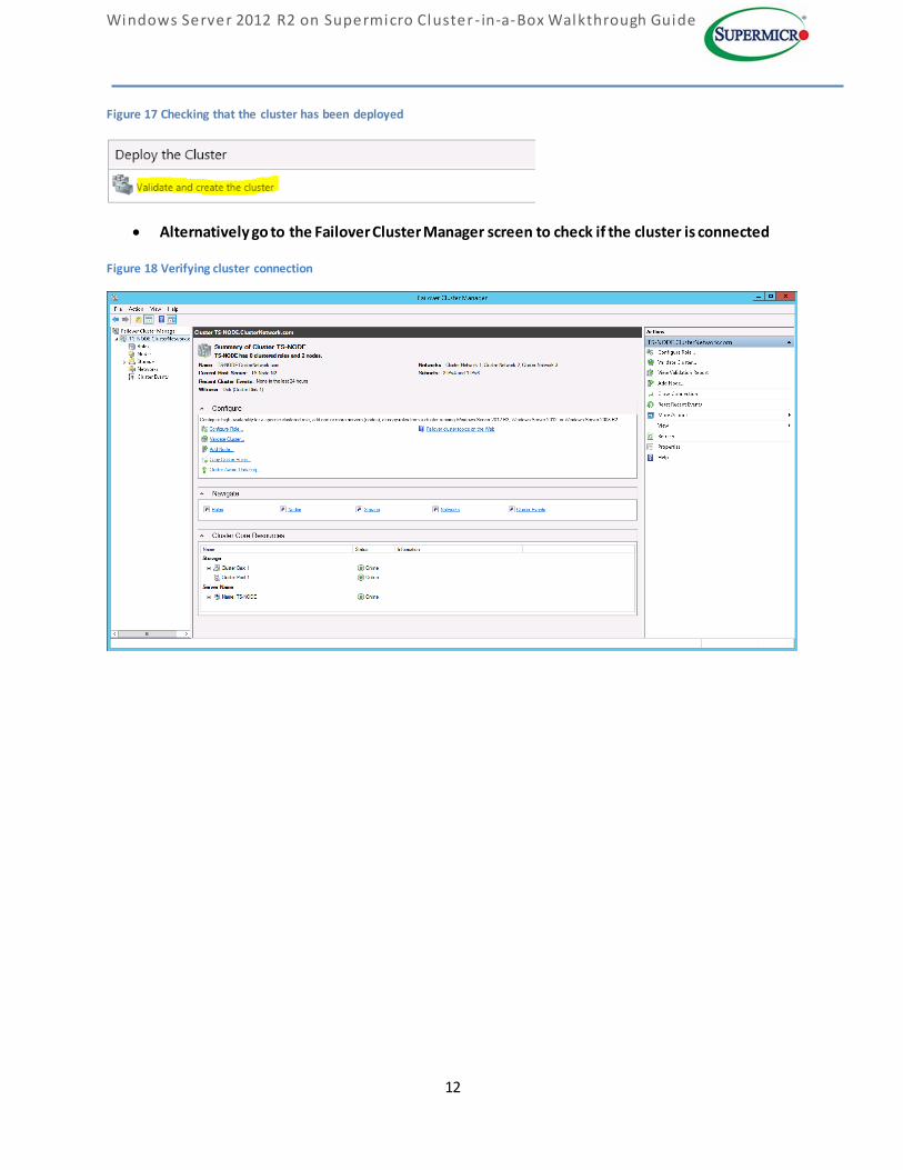
Go to the main node and where it shows Validate and create the cluster the option is greyed out
since the cluster has already been created.
Windows Server 2012 R2 on Supermicro Cluster - in-a-Box Walkthrough Guide
12
Figure 17 Checking that the cluster has been deployed
Alternatively go to the Failover Cluster Manager screen to check if the cluster is connected
Figure 18 Verifying cluster connection
Windows Server 2012 R2 on Supermicro Cluster - in-a-Box Walkthrough Guide
13
2. APPENDIX – Troubleshooting
A. Issues during OOBE / Remote node connection:
1) The default Administrator account password is Admin_123. The Cluster OEM Setup
expects this password to be unchanged in order to maintain a more convenient flow.
(You will be asked to change this password later in the cluster setup process.)
B. Network Configuration
1) Consult your IT / Network / Domain Administrator for the proper configuration of Static
IPs.
2) It is possible to change the “Cluster_Heartbeat” IP addresses from the default settings,
but doing so will cause the ICT menu to become unresponsive. To resolve the
unresponsive issue, close the ICT menu and then restart the menu with the
C:\Windows\system32\oemoobe\OemOOBE.exe application.
C. Joining a Domain Network
1) If you receive a Domain Network “is not accessible” error, please check with your IT /
Network / Domain Administrator that the Domain Network is available.
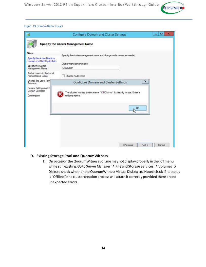
2) If you receive an error that your cluster management name or Node Name “is already in
use”, consult your IT / Network / Domain Administrator to check whether stale Active
Directory objects and/or DNS records exist on the Domain Controller.
Note: After the records have been cleaned return to the previous section as described on
step 1 of page 6 and select the previous screen to ensure that the changes are reflected.
Windows Server 2012 R2 on Supermicro Cluster - in-a-Box Walkthrough Guide
14
Figure 19 Domain Name Issues
D. Existing Storage Pool and QuorumWitness
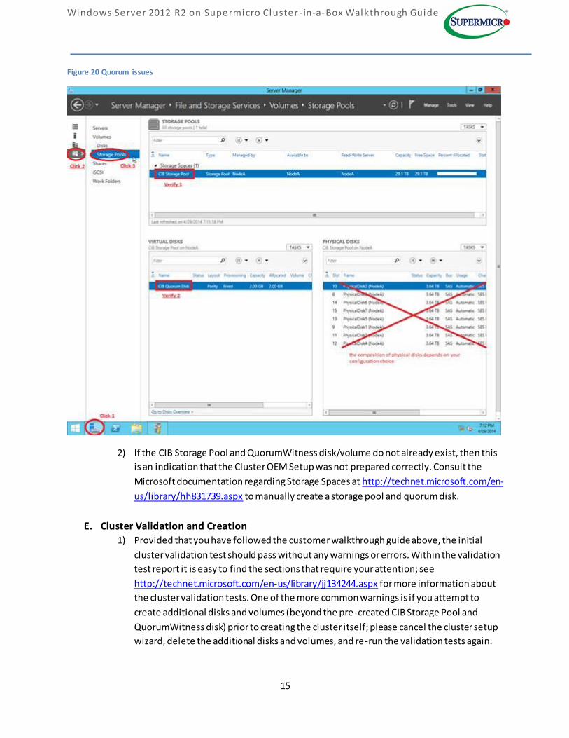
1) On occasion the QuorumWitness volume may not display properly in the ICT menu
while still existing. Go to Server Manager File and Storage Services Volumes
Disks to check whether the QuorumWitness Virtual Disk exists. Note: It is ok if its status
is “Offline”; the cluster creation process will attach it correctly provided there are no
unexpected errors.
Windows Server 2012 R2 on Supermicro Cluster - in-a-Box Walkthrough Guide
15
Figure 20 Quorum issues
2) If the CIB Storage Pool and QuorumWitness disk/volume do not already exist, then this
is an indication that the Cluster OEM Setup was not prepared correctly. Consult the
Microsoft documentation regarding Storage Spaces at http://technet.microsoft.com/en-
us/library/hh831739.aspx to manually create a storage pool and quorum disk.
E. Cluster Validation and Creation 1) Provided that you have followed the customer walkthrough guide above, the initial
cluster validation test should pass without any warnings or errors. Within the validation
test report it is easy to find the sections that require your attention; see
http://technet.microsoft.com/en-us/library/jj134244.aspx for more information about
the cluster validation tests. One of the more common warnings is if you attempt to
create additional disks and volumes (beyond the pre-created CIB Storage Pool and
QuorumWitness disk) prior to creating the cluster itself; please cancel the cluster setup
wizard, delete the additional disks and volumes, and re-run the validation tests again.
Windows Server 2012 R2 on Supermicro Cluster - in-a-Box Walkthrough Guide
16
2) It is HIGHLY RECOMMENDED that you incrementally re-run the cluster validation tests
as you add clustered storage and services in later steps. You can do so by opening the
Failover Cluster Manager, selecting the cluster from the left panel, then selecting
“Validate Cluster..” from the right panel.
F. Removing an Existing Cluster
1) In case you are unsatisfied with your cluster configuration, you may choose to destroy
the cluster so that you can start over.
i. Open the Failover Cluster Manager and select the target cluster from the left
panel. In the right panel, click on “More Actions Destroy Cluster” and confirm
your choice in the following window.
ii. Consult your IT / domain administrator for additional cleanup of stale active
directory objects and DNS records that exist on the domain controller.
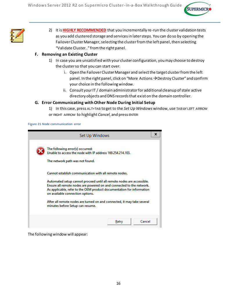
G. Error Communicating with Other Node During Initial Setup
1) In this case, press ALT+TAB to get to the Set Up Windows window, use TAB or LEFT ARROW
or RIGHT ARROW to highlight Cancel, and press ENTER
Figure 21 Node communication error
The following window will appear:
Windows Server 2012 R2 on Supermicro Cluster - in-a-Box Walkthrough Guide
17
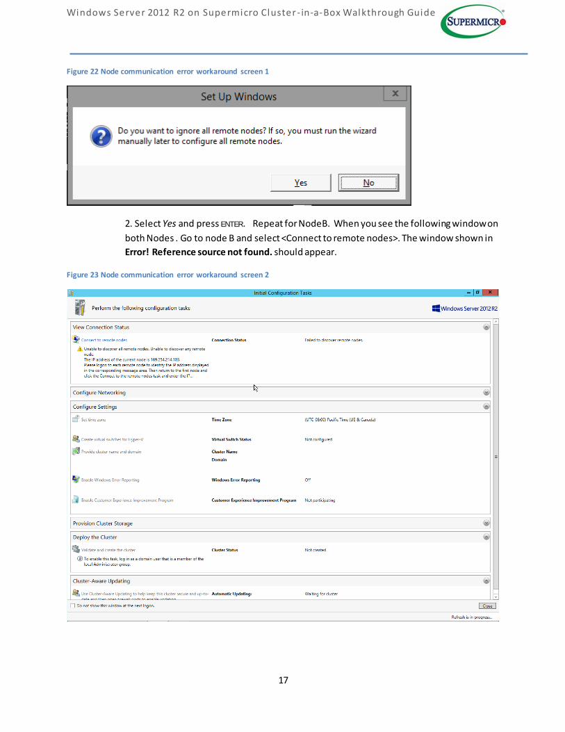
Figure 22 Node communication error workaround screen 1
2. Select Yes and press ENTER. Repeat for NodeB. When you see the following window on
both Nodes . Go to node B and select <Connect to remote nodes>. The window shown in
Error! Reference source not found. should appear.
Figure 23 Node communication error workaround screen 2
Windows Server 2012 R2 on Supermicro Cluster - in-a-Box Walkthrough Guide
18
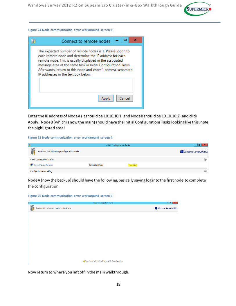
Figure 24 Node communication error workaround screen 3
Enter the IP address of NodeA (it should be 10.10.10.1, and NodeB should be 10.10.10.2) and click
Apply. NodeB (which is now the main) should have the Initial Configurations Tasks looking like this, note
the highlighted area!
Figure 25 Node communication error workaround screen 4
NodeA (now the backup) should have the following, basically saying log into the first node to complete
the configuration.
Figure 26 Node communication error workaround screen 5
Now return to where you left off in the main walkthrough.