Embed Size (px)
Citation preview

By Authority OfTHE UNITED STATES OF AMERICA
Legally Binding Document
By the Authority Vested By Part 5 of the United States Code § 552(a) and Part 1 of the Code of Regulations § 51 the attached document has been duly INCORPORATED BY REFERENCE and shall be considered legally binding upon all citizens and residents of the United States of America. HEED THIS NOTICE: Criminal penalties may apply for noncompliance.
Official Incorporator:THE EXECUTIVE DIRECTOROFFICE OF THE FEDERAL REGISTERWASHINGTON, D.C.
Document Name:
CFR Section(s):
Standards Body:
e


._-
Pamphlet 166 Angle Valve Guidelines for Chlorine Bulk Transportation
• Edition 1 • October 2002 --- ------------------------

i
TABLE OF CONTENTS
1. INTRODUCTION . . . . . . . . . . . . . . . . . . . . . . . . . . . . . . . . . . . . . . . . . . . . . . . . . . . . . . 1
1.1 PURPOSE & SCOPE . . . . . . . . . . . . . . . . . . . . . . . . . . . . . . . . . . . . . . . . . . . . . . . . . . . . . . 11.2 RESPONSIBLE CARE . . . . . . . . . . . . . . . . . . . . . . . . . . . . . . . . . . . . . . . . . . . . . . . . . . . . . 11.3 BACKGROUND . . . . . . . . . . . . . . . . . . . . . . . . . . . . . . . . . . . . . . . . . . . . . . . . . . . . . . . . . . 11.4 DEFINITIONS . . . . . . . . . . . . . . . . . . . . . . . . . . . . . . . . . . . . . . . . . . . . . . . . . . . . . . . . . . . 11.5 DISCLAIMER . . . . . . . . . . . . . . . . . . . . . . . . . . . . . . . . . . . . . . . . . . . . . . . . . . . . . . . . . . . 21.6 APPROVALS . . . . . . . . . . . . . . . . . . . . . . . . . . . . . . . . . . . . . . . . . . . . . . . . . . . . . . . . . . . 21.7 REVISION . . . . . . . . . . . . . . . . . . . . . . . . . . . . . . . . . . . . . . . . . . . . . . . . . . . . . . . . . . . . . 21.8 REPRODUCTION . . . . . . . . . . . . . . . . . . . . . . . . . . . . . . . . . . . . . . . . . . . . . . . . . . . . . . . . 2
2. GENERAL INFORMATION . . . . . . . . . . . . . . . . . . . . . . . . . . . . . . . . . . . . . . . . . . . . . . 2
2.1 PERTINENT REGULATIONS . . . . . . . . . . . . . . . . . . . . . . . . . . . . . . . . . . . . . . . . . . . . . . . . . 2
3. DESIGN REQUIREMENTS . . . . . . . . . . . . . . . . . . . . . . . . . . . . . . . . . . . . . . . . . . . . . . 3
3.1 FLOW . . . . . . . . . . . . . . . . . . . . . . . . . . . . . . . . . . . . . . . . . . . . . . . . . . . . . . . . . . . . . . . . 33.2 DIMENSIONS . . . . . . . . . . . . . . . . . . . . . . . . . . . . . . . . . . . . . . . . . . . . . . . . . . . . . . . . . . . 33.3 VALVE DESIGN, MATERIALS OF CONSTRUCTION . . . . . . . . . . . . . . . . . . . . . . . . . . . . . . . . . . 43.4 GENERAL REQUIREMENTS . . . . . . . . . . . . . . . . . . . . . . . . . . . . . . . . . . . . . . . . . . . . . . . . . 43.5 KEY COMPONENTS . . . . . . . . . . . . . . . . . . . . . . . . . . . . . . . . . . . . . . . . . . . . . . . . . . . . . . 53.6 MANUFACTURER TEST REQUIREMENTS . . . . . . . . . . . . . . . . . . . . . . . . . . . . . . . . . . . . . . . 6
4. PERFORMANCE REQUIREMENTS . . . . . . . . . . . . . . . . . . . . . . . . . . . . . . . . . . . . . . . 6
4.1 REGULATORY APPROVAL . . . . . . . . . . . . . . . . . . . . . . . . . . . . . . . . . . . . . . . . . . . . . . . . . . 64.2 OPERATIONS . . . . . . . . . . . . . . . . . . . . . . . . . . . . . . . . . . . . . . . . . . . . . . . . . . . . . . . . . . 64.3 MAINTENANCE . . . . . . . . . . . . . . . . . . . . . . . . . . . . . . . . . . . . . . . . . . . . . . . . . . . . . . . . . 6
5. REFERENCES . . . . . . . . . . . . . . . . . . . . . . . . . . . . . . . . . . . . . . . . . . . . . . . . . . . . . . . . 8
5.1 INSTITUTE PUBLICATIONS . . . . . . . . . . . . . . . . . . . . . . . . . . . . . . . . . . . . . . . . . . . . . . . . . 85.2 AAR PUBLICATIONS . . . . . . . . . . . . . . . . . . . . . . . . . . . . . . . . . . . . . . . . . . . . . . . . . . . . . 85.3 ASME STANDARDS . . . . . . . . . . . . . . . . . . . . . . . . . . . . . . . . . . . . . . . . . . . . . . . . . . . . . . 85.5 TC REGULATIONS . . . . . . . . . . . . . . . . . . . . . . . . . . . . . . . . . . . . . . . . . . . . . . . . . . . . . . . 95.6 OTHER PUBLICATIONS . . . . . . . . . . . . . . . . . . . . . . . . . . . . . . . . . . . . . . . . . . . . . . . . . . . . 9
APPENDIX A VALVE MANUFACTURER INFORMATION . . . . . . . . . . . . . . . . . . . . . . . . . . . . . . . . . 10
ANGLE VALVE SELECTION GUIDELINESFOR CHLORINE BULK TRANSPORTATION 1
1. INTRODUCTION
1.1 PURPOSE & SCOPE
The purpose of this pamphlet is to set forth performance/selection criteria that should beutilized in identifying valves other than the �‘standard�’ that are suitable for use on bulk, liquidchlorine, transportation equipment. This pamphlet contains information pertaining tostandardization, performance and design criteria as well as an appendix that includesinformation on valves that meet these criteria.
1.2 RESPONSIBLE CARE
Members of the Chlorine Institute pledge to follow the elements of a responsible careprogram such as the American Chemistry Council�’s or the Canadian Chemical ProducersAssociation�’s (CCPA) Responsible Care® initiatives. The Chlorine Institute is a PartnerAssociation in the American Chemistry Council�’s Responsible Care® initiative and iscommitted to the support of a continuing industry effort to ensure the responsiblemanagement of chemicals. This pamphlet demonstrates support of these principles.
1.3 BACKGROUND
For over 50 years the Chlorine Institute Standard Angle Valve has effectively served theneeds of bulk chlorine shippers throughout North America; helping to ensure safe andefficient transportation of chlorine from the producer to the end user. Nevertheless, overthis period of time significant changes in valve technology have been brought to themarketplace. Indeed other valves have been sanctioned by the AAR for use on chlorinetank cars.
For this reason, the Institute has determined that it is best to move away from the conceptof a �“standard�” angle valve. The goal is to develop a performance/selection criteria thatindividuals and/or corporations can utilize to select a valve that most appropriately meetstheir needs, while still being confident that the Institute�’s collective knowledge andexperience supports their choice. Hence the development of this pamphlet.
1.4 DEFINITIONS
In this pamphlet the following meanings apply unless otherwise noted:
AAR Association of American Railroads
ASME American Society of Mechanical Engineers
ASTM American Society for Testing and Materials
CFR Code of Federal Regulations
Chlorine dry chlorine (either gas or liquid)
DOT U.S. Department of Transportation

2 PAMPHLET 166
Institute The Chlorine Institute, Inc.
OSHA Occupational Safety and Health Administration
psig pounds per square inch gage
PTFE polytetrafluoroethylene
TC Transport Canada
1.5 DISCLAIMER
The information in this pamphlet is drawn from sources believed to be reliable. The Instituteand its members, jointly and severally, make no guarantee, and assume no liability inconnection with any of this information. Moreover, it should not be assumed that everyacceptable procedure is included, or that special circumstances may not warrant modifiedor additional procedure. The user should be aware that changing technology or regulationsmay require a change in the recommendations herein. Appropriate steps should be takento insure that the information is current when used. These suggestions should not beconfused with federal, state, provincial, municipal or insurance requirements, nor withnational safety codes.
1.6 APPROVALS
1.6.1 Valves
The AAR Tank Car Committee/DOT has approved various angle valves for use on chlorinetank cars.
1.6.2 Pamphlet
The Institute�’s Storage and Transport Committee approved Edition 1 of this pamphlet onSeptember 25, 2002.
1.7 REVISION
Suggestions for revision of the contents of this pamphlet should be directed to the Secretaryof the Institute.
1.8 REPRODUCTION
The contents of this pamphlet are not to be copied for publication, in whole or in part,without Institute permission.
2. GENERAL INFORMATION
2.1 PERTINENT REGULATIONS
The DOT and TC regulate the packaging and transportation of hazardous materials.Because chlorine is a hazardous material, personnel involved in any aspect of handling

ANGLE VALVE SELECTION GUIDELINESFOR CHLORINE BULK TRANSPORTATION 3
packaging and transportation of chlorine should be knowledgeable of the regulatoryrequirements pertaining to chlorine. Publications should be readily available for reference.For ordering information, see Section 5. The DOT hazardous material regulations forshipping chlorine are found in Title 49 CFR parts 171 to 180. The regulations for shippinghazardous materials in Canada can be found in TC�’s Transportation of Dangerous GoodsRegulations. Although the U.S. and Canadian regulations are similar, there are somedifferences. The concerned reader should consult the references contained in Section 5for detailed information.
3. DESIGN REQUIREMENTS
3.1 FLOW
The valve flow passages shall be designed so that in a typical chlorine tank car unloadingsituation, with a differential pressure (tank car pressure - valve outlet pressure) ofapproximately 20 psig, a nominal unloading rate of 20,000 pounds per hour can beachieved.
3.1.1 Valve Flow Coefficient
Angle valves currently in service have flow coefficients (Cv) in the range of 12 through 23.
3.1.2 Excess Flow Valves
Chlorine bulk transports are currently equipped with excess flow valves that are rated forup to approximately 30,000 lbs of chlorine per hour. For highway applications, regulationsstate that the excess flow system must be certified to activate when unloading hose shears.Use of high capacity valves, coupled with high capacity excess flow valves, may requireunique certification. For more information, see Pamphlet 49 (5.1.3).
3.2 DIMENSIONS
Chlorine angle valves shall have a common set of keys dimensions to assureinterchangeability and commonality of emergency procedures.
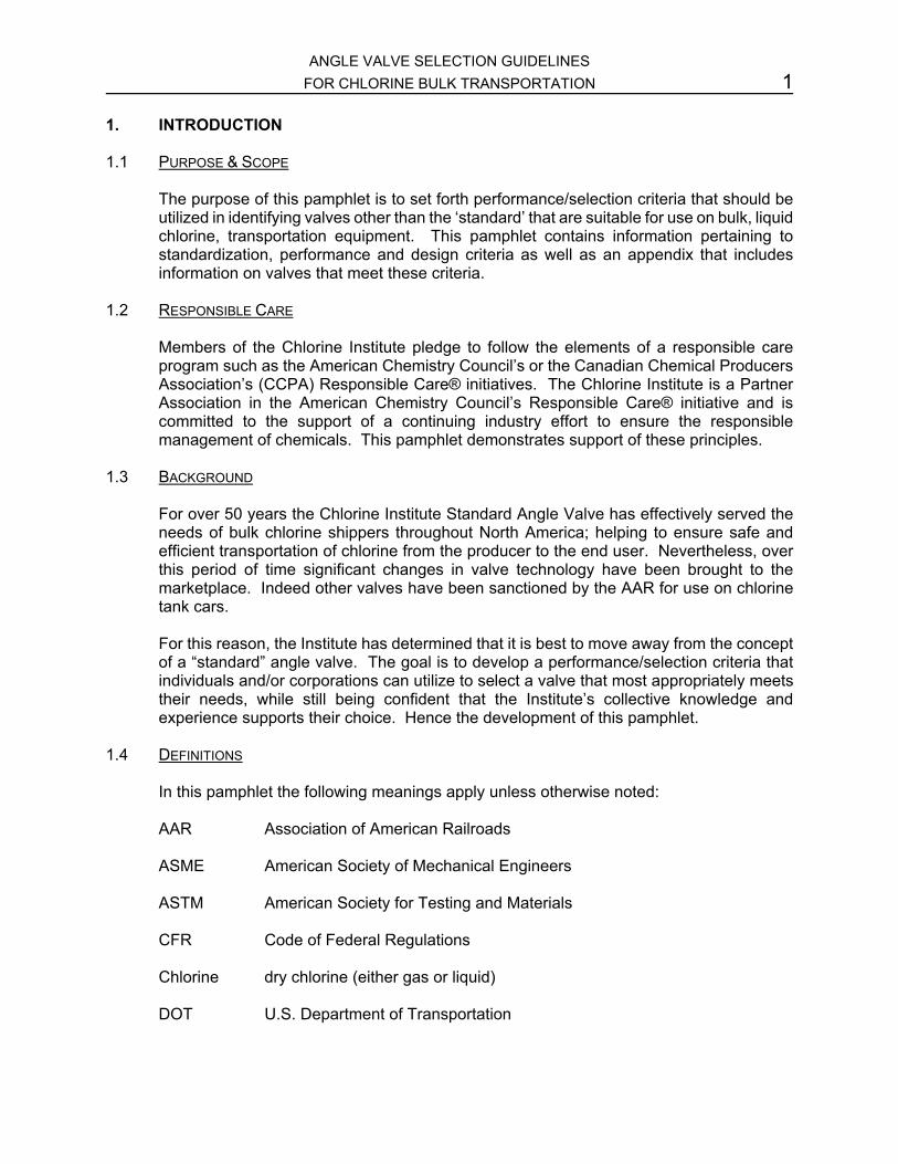
3.2.1 Outline dimensions
Key reference dimensions are given in Figure 1 �“Angle Valve Reference Dimensions�”.
3.2.2 Emergency Kit application
Chlorine angle valves must be designed to be compatible with device 6 in the ChlorineInstitute�’s Emergency Kit C (5.1.7).
3.2.3 Tank Car Connection
Chlorine angle valves must fit to bulk transport manway covers as defined with ChlorineInstitute Drawing 103 (5.1.9). Attaching hardware shall be consistent with specificationsoutlined in Chlorine Institute Drawing 102, (5.1.8). Stud lengths may vary depending onvalve design. It should be noted that although the flange on a standard ASME B 16.34
VALVE OPEN MAX: 13-5/8 inches
rANDLE DIAMETER: 5-112 inches
BASE TO OUTLET CENTERLINE: 3-9/16 inches
FLANGE HOLES: (4) 013/16" or 7/8", equally spaced on 3-1/2" bolt circle straddling outlet centerline.
BASE-TONGUE EXTENTION: 1/4 inch depth, 2.245 inch 00, 1.50510
ALTERNATE 1
Figure 1
See Figure 2
Chlorine Valve
6A1 Hood
Molded Viton@ Gasket
ALTERNATE 2
5.72" Inside Dia.
~

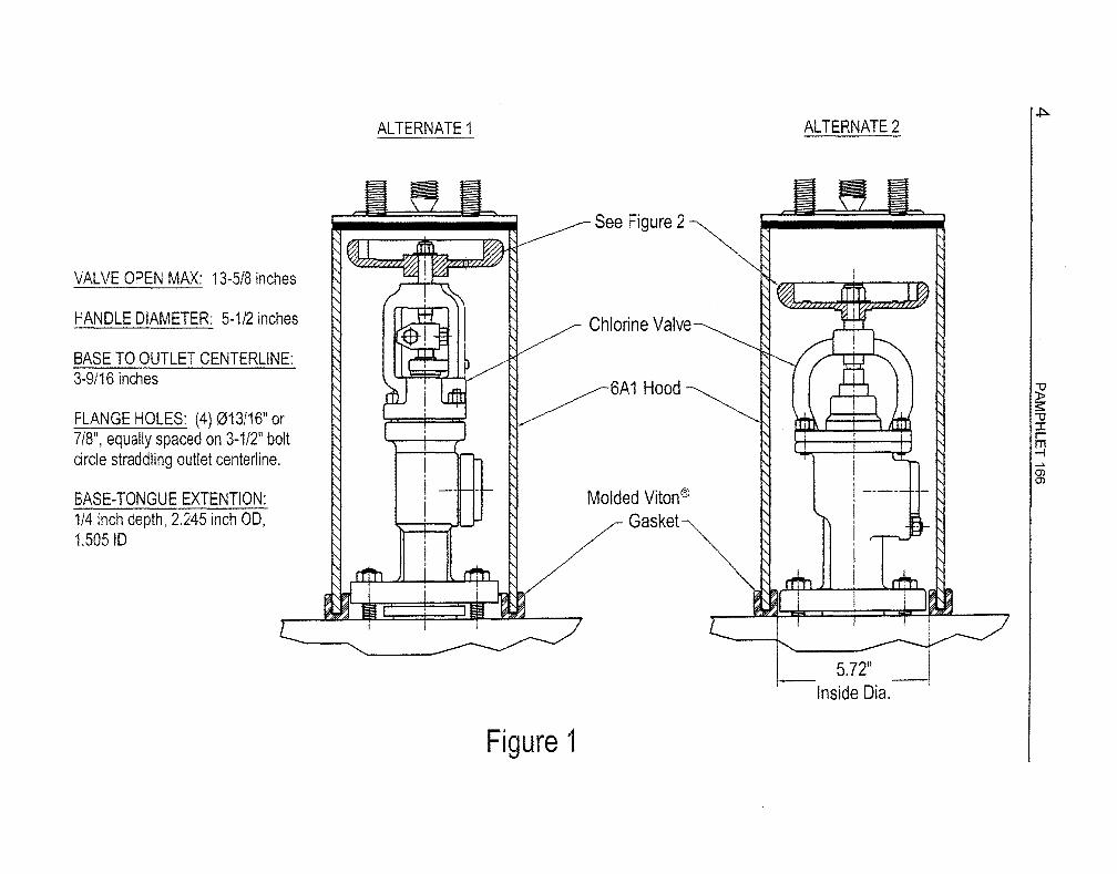
3.63 ±.06 REF SEE NOTE 1
NOTES:
~.
?:fv~ i CI.O () ,,' ~«'
__ , __ ,'/.$ +"l_ \ \ I -_._-
"~ __ /'
/
1----- 3.63 ±.OS REF ____ -/ SEE NOTE 1
1------ 04.2S±.06 REF ------
1) ACCEPTS 3.50" SQUARE WITH 04.63" CORNERS TO GO 0.63" DEEP MINIMLM.
2) CLEARANCE REQUIRED FOR STEM NUT AND WASHER.
Figure 2
0.28 REF
0.66 REF SEE NOTE 1
05.50 1.13 REF SEE NOTE 2
I
SECTION A-A 1.40
REF
11 o » ;;0 Z
() ~ ::r: m I < o » ~ r Z < m m OJ (f) c m I r A m -i (') ;;0 ::! » 0 z Z (J) (j) -0 C o -;;0 0 -i m ~ C _ Z o m z (J)
01

6 PAMPHLET 166
class 300 valve has 7/8" bolt holes, the Chlorine Institute standard angle valve specifies13/16" bolt holes and valve purchasers may continue to require this dimension on othervalve designs.
3.2.4 Outlet Connection
The valve outlet connection shall be a one inch female NPT. The outlet connection can bean integral part of the body or built as a replaceable assembly.
3.3 VALVE DESIGN, MATERIALS OF CONSTRUCTION
3.3.1 Design Pressure
Valves shall meet or exceed all requirements for ASME B 16.34 (5.3.1), Class 300 exceptflange dimensions (ref. 3.2.1, 3.2.3) and minimum pressure test requirements (ref 3.6.1).The use of materials not cited in ASME B16.34 should be appropriately documented by thevalve manufacturer.
3.3.2 Design Temperature
Valves shall be rated or qualified by ASME B31.3 (5.3.2) for a process temperature of -40°F (-40°C) or lower.
3.4 GENERAL REQUIREMENTS
Valves shall be angle-body, hand actuated globe type. Closure sealing can be either softseated or metal seated. Soft seated valves shall be designed so that the valves will providesubstantial closure even if the soft seat is damaged or displaced. Stem seals can utilizebellows or packing/o-rings. In either case, backup packing or o-rings are required.
3.4.1 Materials Table
The following table lists materials which have been successfully used in chlorine angle valveservice. Choice of specific materials depends on a combination of factors, includingchemical resistance, mechanical strength, manufacturing experience and economics.
Part Material
Body* Low temperature. carbon steel ASTM A352, Gr LCB or ASTM A350, GradeLF2 or Monel casting ASTM A494, M35.1 or ASTM A105 normalized**
Bonnet Carbon steel, monel
Disk Hastelloy C-276, monel 500, fluorocarbon insert
Bellows Hastelloy C-276
Stem Hastelloy C-276, monel 500
Seat Monel 400, Stellite facing, Hastelloy C-276
Packing Fluorocarbon
O-rings Viton

ANGLE VALVE SELECTION GUIDELINESFOR CHLORINE BULK TRANSPORTATION 7
Part Material
Nuts ASTM A194 Grade 4, monel
Bolts/studs ASTM A320 Grade L7, monel
Gaskets See Pamphlet 95
Handwheel Cast iron
* All body castings must meet the quality requirements contained in the AAR Specifications forTank Cars, Appendix M, Section 4.9. (5.2.1)
** Must be impact tested in accord with paragraph. 323.3 of ASME B31.3 (5.3.2)
3.5 KEY COMPONENTS
3.5.1 Marking
All valves will be marked to indicate:
�• the name or identifying mark of the manufacturer
�• manufacturer�’s design or type number
�• type of trim
�• pressure-temperature limitations
�• unique serial number
3.5.2 Handwheel
Handwheel designs should accommodate adapters for remote actuators as shown in Figure2.
3.5.3 Closing/Turning Torque
Valve designs shall ensure that over-torquing will not result in a failure that will allow achlorine release. Normal and maximum closing/turning torque shall be stated by themanufacturer.
3.5.4 Lubrication
Lubrication fittings shall be provided for bearing surfaces. Valve components shall beassembled as necessary to facilitate operation and disassembly after a period of threeyears. Use only non-reactive lubricants for parts in contact with chlorine.
3.5.5 Valve Position Indication
All valves will have a method for determining whether the valve is open or closed.

8 PAMPHLET 166
3.6 MANUFACTURER TEST REQUIREMENTS
3.6.1 Not withstanding other requirements contained in ASME 16.34, a minimum pressure of 500psig shall be utilized for the required shell and closure testing.
3.6.2 Test and acceptance criteria Table
All manufacturers should have a quality assurance/quality control (QA/QC) system in placethat ensures material documents as well as availability of test data for a minimum of tenyears. Upon request valve manufacturers shall provide documents demonstrating theresults of the tests required by ASTM, ASME, the valve manufacturers quality assuranceprogram and user requirements.
4. PERFORMANCE REQUIREMENTS
4.1 REGULATORY APPROVAL
Each valve design must pass a regulatory review which shall include a service trial.
4.2 OPERATIONS
Each valve design should remain operable in chlorine service over a minimum three yearservice cycle. Operable is defined as follows:
�• no product leak to atmosphere through all leak paths using aqua ammonia vaportest
�• no product leak through the stem-seat area during post loading inspection usingaqua ammonia vapor test
�• be operable by hand without the use of wrenches
�• maintain essentially the original exterior finish
Note: When testing the system for leaks with aqua ammonia, care must be taken thatchlorine has diffused throughout the piping system before leak checking with ammonia. Thereaction of ammonia vapor with escaping chlorine forms a dense white cloud. The mostconvenient way to use ammonia for this purpose is to direct the vapor from a plasticsqueeze bottle containing 26 degree Baume�’ aqua (ammonia solution) at the suspectedleak. Do not squirt liquid aqua ammonia on pipe fittings.
4.3 MAINTENANCE
An angle valve service interval shall be defined for each valve design. Valves may beserviced in the field or sent to a designated shop. It is recognized that this service intervalwill be influenced by the process conditions present at the loading and unloading sites.Member companies must determine the proper maintenance interval for their fleets toprevent service failures. A rebuilt valve will be leak tight at 500 psig using closureprocedure in ASME B16.34.

ANGLE VALVE SELECTION GUIDELINESFOR CHLORINE BULK TRANSPORTATION 9
5. REFERENCES
5.1 INSTITUTE PUBLICATIONS
5.1.1 Chlorine Manual, ed. 6; Pamphlet 1; The Chlorine Institute: Arlington, VA, 1997.
5.1.2 Piping Systems for Dry Chlorine, ed. 14; Pamphlet 6; The Chlorine Institute: Arlington, VA,1998.
5.1.3 Recommended Practices for Handling Chlorine Bulk Highway Transports, ed. 8; Pamphlet49; The Chlorine Institute: Arlington, VA, 2001.
5.1.4 Emergency Shut-Off Facilities for Tank Car and Tank Truck Transfer of Chlorine, ed. 3;Pamphlet 57; The Chlorine Institute: Arlington, VA, 1997.
5.1.5 Recommended Practices for Handling Chlorine Tank Cars, ed. 3; Pamphlet 66; TheChlorine Institute: Arlington, VA, 2001.
5.1.6 Gaskets for Chlorine Service, ed. 2; Pamphlet 95; The Chlorine Institute: Arlington, VA,1997.
5.1.7 Instruction Booklet: Chlorine Institute Emergency Kit �“C�” for Chlorine Tank Cars and TankTrucks, ed. 8; Pamphlet IB/C; The Chlorine Institute: Arlington, VA, 1996.
5.1.8 Studs, Nuts and Gaskets for Chlorine Tank Manway Covers and Valves, Drawing; DWG102-10; The Chlorine Institute: Arlington, VA, 2001.
5.1.9 Manway Cover for Chlorine Tank Cars and Cargo Tanks, Drawing; DWG 103-8; TheChlorine Institute: Arlington, VA, 2001.
5.2 AAR PUBLICATIONS
5.2.1 Specifications for Tank Cars - Section C, Part III - M-1002; Association of AmericanRailroads: Washington, DC, 2000.
5.3 ASME STANDARDS
5.3.1 Valves - Flanged, Threaded and Welding End, ASME B16.34, an ANSI standard; TheAmerican Society of Mechanical Engineers: New York, NY, 1996.
5.3.2 Process Piping, ANSI/ASME Code for Pressure Piping; ASME B31.3, an ANSI standard;The American Society of Mechanical Engineers: New York, NY, 1996.
5.4 DOT REGULATIONS
5.4.1 Code of Federal Regulations. Title 49. Parts 100-185. Office of the Federal RegisterNational Archives and Records Administration. U.S. Government Printing Office:Washington, DC, (revised annually).
10 PAMPHLET 166
5.5 TC REGULATIONS
5.5.1 Guide to Canadian Transportation of Dangerous Goods Act and Regulations, mini version;ICC International Compliance Center Ltd: Mississauga, Ontario, 2001.
5.5.2 Construction and Maintenance of Tank Car Tanks and Selection and use of Tank CarTanks, Portable Tanks and Rail Cars for the Transportation of Dangerous Goods by Rail;CAN/CGSB-43.147-2002; Canadian\ General Standards Board: Ottawa; 1997.
5.6 OTHER PUBLICATIONS
5.6.1 Responsible Care®. Several brochures, pamphlets, videos and merchandise on the sixCodes are available and are updated periodically. Lending Library of Audiovisual TrainingPrograms. American Chemistry Council: Arlington, VA.

ANGLE VALVE SELECTION GUIDELINESFOR CHLORINE BULK TRANSPORTATION 11
For further assistance and information on items referenced, contact:
Association of American Railroads (AAR)Transportation Technology Center, Inc.P.O. Box 11130Pueblo, CO 81001877-999-8824719-584-7157 (Fax)http://www.aar.org
American Society of Mechanical EngineersUnited Engineering Center345 East 47th StreetNew York, NY 10017212-705-77401-800-843-2763 (publications)
Canadian General Standards BoardPlace du PortagePhase III, 6B111 Laurier StreetHull, Quebec K1A1G6 (CANADA)819-956-04251-800-665-2472 (Canada only)819-956-5644 (Fax)http://www.pwgsc.gc.ca/cgsb
American National Standards Institute (ANSI)11 West 42nd StreetNew York, NY 10036212-642-4900212-302-1286 (Fax)http://www.ansi.org
American Chemistry Council1300 Wilson BoulevardArlington, VA 22209703-741-5000703-741-6000 (Fax)http://www.AmericanChemistry.com
Canadian Government PublishingPWGSCOttawa, Ontario K1A OS9 (CANADA)819-956-4802 (Regulation Purchases)http://publications.pwgsc.gc.ca
Superintendent of DocumentsGovernment Printing OfficeWashington, DC 20402202-512-1800 (Sales)http://www.access.gpo.gov
The Chlorine Institute, Inc.1300 Wilson BoulevardArlington, VA 22209703-741-5760703-741-5768 (Fax)http://www.CL2.com

12 PAMPHLET 166
APPENDIX A
This appendix contains information on valves that meet these guidelines and are approved for use
on chlorine bulk transportation in North America. The information has been provided by the valve
manufacturer. Questions on the content should be sent to the appropriate company.

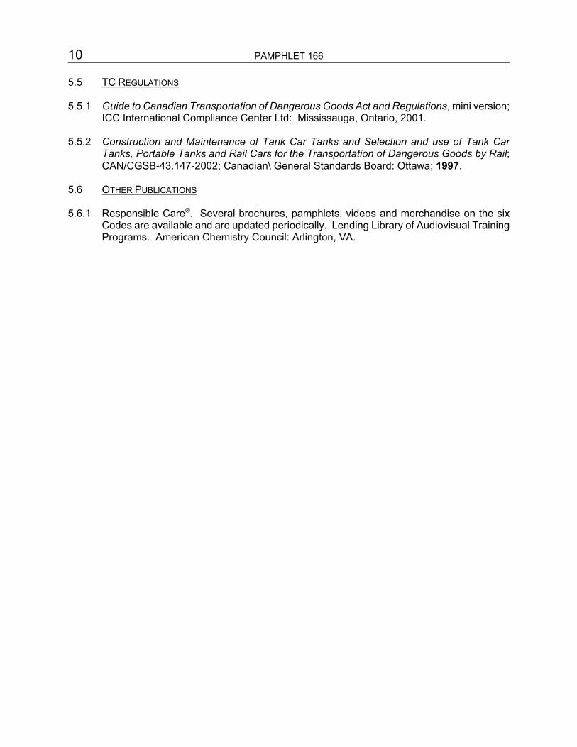
1. Valve Manufacturer: Address:
Beltech Valves 2728 S. Ruby Avenue Gonzales, LA 70737 225-644-6110 225-644-6118 (fax)
2. 1" Bellows Sealed Angle Valve Beltech BMV017 Manually Operated Valve
3. Drawing of Valve: Beltech Assembly Drawing 550017
4. Identify key dimensions (metal thickness): See Drawing 550017
5. Materials of Construction: See Bill of Material on Drawing 550017
6. Flow coefficient, Cv = 23
7. Special features (seat type, operation):
8.
9.
Field replaceable Hastelloy C276 Seat Insert Field replaceable reinforced PTFE Flat Faced Seat Disc. Metal to Metal seating with 900 seat available Shear Key equipped Handwheel to prevent seat damage and stem bending Handwheel internal design to accept standard air motor operator assembly Split and Keyed Stem Guide to prevent stem rotation Stem Nut equipped with Thrust Needle Bearings for smooth operation All fasteners are of non-ferrous materials to prevent corrosion and ease of maintenance Outlet Plug equipped with a %" square female socket to accept standard ratchet wrench Valve Body is convertible to accept the BPV024 Pneumatic Operating Cylinder Valve Body standard material is Monel 400 for increased corrosion resistance
Approvals (AAR, DOT, USCG, etc.): AAR Approval #E 969029
Quality Assurance Program: Conforms to AAR M 1003
10. Torque Requirements, Limitations:
Critical Torque Values Seating Torque
Seat Deformation
Key Shear
Stem Column Buckling (Monel K500)
20 FT-LBS
35 FT-LBS
88 FT-LBS
98 FT-LBS

FLANGEAT 50
II
METAl SEAT 10 COMPONENTS
(OPTIONAl) 11
12
13
15
14
20 FT.lBS. ASSEM8t...E'MTH LCCTITE2C2 -45
42 43 44 16
36
46
18
PtOTOATE
03-21-02
21
22 23 24
25
26
10 27 28
HANDVMEEL TOP VIEW
NOTES; i) INSTAll PACKING FLANGENL'f
UNnL IT COUT ACTS THE GWO FlANGE. TURN ClOCKWSE 1 ADDITIONAL TURN. THIS IS FO~ THE INlnAl ASSEMBLY ONLY. AOOITIONAL TIGHTENING MAYBE REQUIRED flFTE.R VALVE HAS BEEN IN SERVICE.
2) TURN SETSCREWlI2TiJRNA-"TER CONTACTIN3 STEM NUT.
TInS ORAV'AHG AND ALL IHFOfMATION iT COtfLAJNS {S THE"COHADENTIAL AAOF£Rn" Of BELTE.CR NO COPlEn OF THIS QRA'MNG OR ANY PORTION Of TH!S DRAWING SHALL BE ",&,DE. UPON REQUEST, THIS OAAWNG MUST Be ReTORNEOTO BELTECH.
11Tle:
BELTECH 2728 a Ruby !we.
Gooni .. , LA 70737 Pt~ne: (2254) 64Hl10
BEL TECH 1" CLASS 300# MDV GENERAL ASSEMBLY AND PARTS LIST
AAR Approval # E 969029 DRAWiOO NUMBER
550017 SC'l.E
N1S
1. Valve Manufacturer: Address:
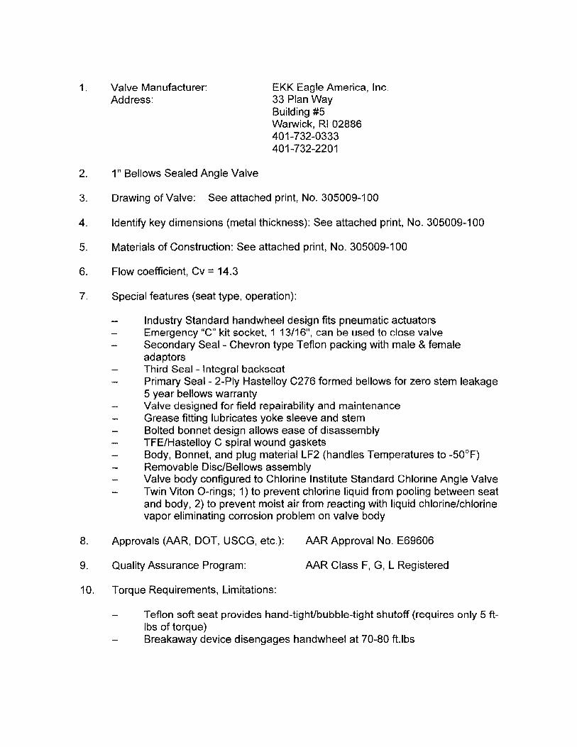
EKK Eagle America, Inc. 33 Plan Way Building #5 Warwick, RI 02886 401-732-0333 401-732-2201
2. 1" Bellows Sealed Angle Valve
3. Drawing of Valve: See attached print, No. 305009-100
4. Identify key dimensions (metal thickness): See attached print, No. 305009-100
5. Materials of Construction: See attached print, No. 305009-100
6. Flow coefficient, Cv = 14.3
7. Special features (seat type, operation):
8.
9.
Industry Standard handwheel design fits pneumatic actuators Emergency "e" kit socket, 1 13/16", can be used to close valve Secondary Seal- Chevron type Teflon packing with male & female adaptors Third Seal - Integral backseat Primary Seal - 2-Ply Hastelloy C276 formed bellows for zero stem leakage 5 year bellows warranty Valve designed for field repairability and maintenance Grease fitting lubricates yoke sleeve and stem Bolted bonnet design allows ease of disassembly TFE/Hastelloy C spiral wound gaskets Body, Bonnet, and plug material LF2 (handles Temperatures to -50°F) Removable Disc/Bellows assembly Valve body configured to Chlorine Institute Standard Chlorine Angle Valve Twin Viton a-rings; 1) to prevent chlorine liquid from pooling between seat and body, 2) to prevent moist air from reacting with liquid chlorine/chlorine vapor eliminating corrosion problem on valve body
Approvals (AAR, DOT, USCG, etc.): AAR Approval No. E69606
Quality Assurance Program: AAR Class F, G, L Registered
10. Torque Requirements, Limitations:
Teflon soft seat provides hand-tightlbubble-tight shutoff (requires only 5 ftIbs of torque) Breakaway device disengages handwheel at 70-80 ft.lbs

------1'15
11 3/8
------------¢5------------ S!£M IRA'@. • 31 It!CH FlOW CO£lfIClENT Cv li.3 WElGHT (lBS.) 19.0
""""'"s "'"
14 'tI'El'£l'f,f31et.. SST. t/V/Ol
" ~"
IlE\I 31 W~ lN3EI..
[Q2J 2 RET.AJNlNG RING BI0683+ [Q2J 3 SHOO PIN BI06815 [Q2J 1 OUTER SHtAR tllJI AI068H rmJ I INNER SHtAR NUT AI06813
2 O-RING AI 06472 1 I WARNING lABEl I AI06448
CARBON srm 303 sm. S1L MONEl. K-SOO MONEl. K-SOO WON .ALUMlllut.I
~ ~ M 33 32 31
1 I NANE Pl.AlE I AI 06261 I .ALUMlllut.l I 30 1 =1 C.A.BLE ftSS'( 1 A205330 I CARBCN S1L I 29
IQIJ 1 PLUG Al 06658 A350 1F2 28 I
rmJ 1 1W10WHEEl. NUT A170031 CARBCN S1L 27 J f9ll IQIJ 1 1W10WHEEl. Bl06259 t.W.t.rult.£ IRON 26
ffill 1 GREASE flTTING Al 06-«7 CARBON S1L 25 IQIJ 2 COUAlR AI06+46 MONEl. K-SOO 24 IQIJ 1 YOKE SlEEVE AI06«5 MONEl. K:"'SOO 23
2 HEX. NUT AI70025 CAROON S1L 22 1 I GtmD Pl.AlE I A170019 I CARBCN S1L I 21
IQIJI ~ GL'ND BUSHING I Al06«4 I MONEl. 400 20 1 PACKING A170110 TFE 19
IQIJ 2 PIN AlO6443 CARBON S1L 18 IQIJ 2 GL'ND BOlT AI 06442 CARBON S1L 17 IQIJ 4 JOINT BOlT AI 06657 A320 L7 16 ffill 1 GASKET Al 06-«1 i TFE/HASTEllOY C 15
'I ffill 1 GASKET A170109 OY C 14 1 GUIDE PIN AI06«0 MONEl. K-SOO 13 • STEt.! AI06624 MONEl. K-SOO 12
BEllOWS HOlDER I AI06623 I HASTEllOY C276 I 11 BEllOWS I A205366 I HASTru.OY C276 I 10 PIN I AI06438 I HASTru.OY C276 I 9 NUT RET.AJNER SEAT RING DISC
IQIJI 1 I BOHNET
SEAT GASKET SEAT
IQIJ! 1 I BODY Q'IY NOUENClATURE
Al 06437 AI06436 AI 06435 AI 06622 CI06656 AI 06432 BI06431 CI06655
PNrr t«JIIIIER
t.IONEl. 400 I 8 MONa 400 I 7 lFE (Q.ASS F1IlEDlI 6 HASTru.OY C276 I 5 A350 Lf2 4 GARlOCK 3510 3 MONEl. 400 I 2
A350 Lf2 I 1 IIAl£RW. IlW NO.
Ir.C EAGLE AMERICA, INC.
1 INCH ANGLE VAlVE m 02

* Industry Standard handwheel design
fits pneumatic actuators
• Breakaway device disengages handwheel
at 70·80 tUbs.
* Emergency "C" .kit socket, 113/16", can be used
to close valve
"Secondary Seal" Chevron type Teflon
packing with male & female adaptors
RIGHT A~~bcE VAb\{J;~ AAR APPROVAL No. E69606
VALVE IS DESIGNED FOR FIELD REPAIRABILITY AND MAINTENANCE
Grease fitting lubricates yoke sleeve and stem
~ Bolted bonnet design allows /" ease of disassembly
"Third Seal" Integral backseat __________
TFE/Hastelloy C spiral wound gaskets
"Primary seal" 2·Ply Hastelloy C276
formed bellows for zero stem leakage
5 Year bellows warranty
Removable DiscI Bellows assembly
Ease of operation; Teflon soft seat provides
hand.tightlbubble-tight shutoff (requires only S ft·lbs of torque)
Vallie body configured to Chlorine Institute Standard
Chlorine Angle Valve
Body, bonnet, and plug material LF2 (handles Temperatures to -SO°F)
Twin Viton O-rings; (1) to prevent chlorine liquid
from pooling between seat and body
(2) to prevent moist air from reacting with liquid chlorine! chlorine vapor eliminating corrosion problem on valve body
ISO 9002 CERTIFIED AAR CLASS F1 G1 L REGISTERED
EICIC EAGLE AMERICA, INC.
1. Valve Manufacturer: Address:
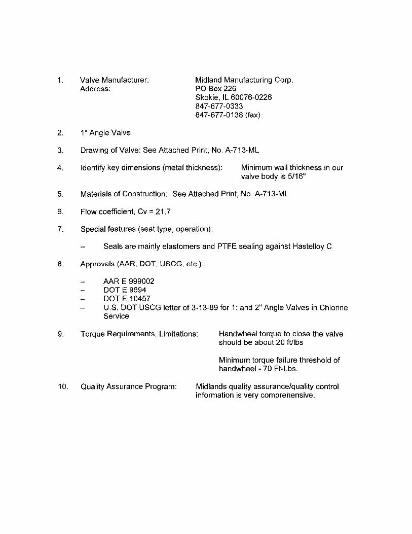
Midland Manufacturing Corp. PO Box 226 Skokie, IL 60076-0226 847 -677 -0333 847 -677 -0138 (fax)
2. 1" Angle Valve
3. Drawing of Valve: See Attached Print, No. A-713-ML
4. Identify key dimensions (metal thickness): Minimum wall thickness in our valve body is 5/16"
5. Materials of Construction: See Attached Print, No. A-713-ML
6. Flow coefficient. Cv = 21.7
7. Special features (seat type, operation):
Seals are mainly elastomers and PTFE sealing against Hastelloy C
8. Approvals (MR, DOT, USCG, etc.):
9.
AAR E 999002 DOT E 9694 DOT E 10457 U.S. DOT USCG letter of 3-13-89 for 1: and 2" Angle Valves in Chlorine Service
Torque Requirements, Limitations: Handwheel torque to close the valve should be about 20 ftllbs
Minimum torque failure threshold of handwheel - 70 Ft-Lbs.
10. Quality Assurance Program: Midlands quality assurance/quality control information is very comprehensive.

HEX NUTS ACROSS FLATS)
11 7/16 OPEN 1) 15/16 CLOSED
PART NAME MATERIAL
VlHEEL CAST IRON
EM HASTELLOY C.
3 1 ISEAL RETAINER MONEL
4 1 BODY MONEL
2-~ IBONNET MONEL
6 1-
7 1 OUTLET FLANGE MONEL "'"
8 1 PACKING seREVI MONEL
9 J BODY INSeRT HASTElLOY C,
10 1 SEAT SUL PTFE
5 PACKING <ING PTFE
12 2 STEM O-EING VITON
13 2 OUTLET [-RING VlTON
14 1 NYLON INSERT LOCKNUT STAINLESS STL
15A 7 STUD MONEL
15H 7 NUT MONEL
15C 7 LOCKVI ASHER MONEL
16 1 PIPE PLU:; & CHAIN MONEl/STN, STL
17 1 PACKING SPRING INCONEL
18A 1 U-BOLT MONEL
18B 2 LOCKNUT MONEL
19 1 RETAINER PIN HASTELLDY C
20 1 RETAINER NUT INCONEL
21 1 MALE PACKING
MONEL ADAPTER
22 1 OUTLET FLANGE GYlON GASKET
23 2 BODY O-RING VI TON
24 1 INSERT G~SKET LEAD-
25 1 NAMEPLATE MONEL
PLASTIC
PTFE
)( rU ... ILr.nn, ... ,,,, ...... ,-.',- .>.,,--.. --~
PART NO,
713-1-C:
713-2-HC
713-303-ML
713-4-ML
713-5-ML
713-7-ML
713-81-HL
713-9-HC
713-10- -F
713-11-TF
713-12-vL
713-13-Vl
713-14->$
713-151-ML
713-153-ML
713-152-ML
713-162-ML
713-17-:N
713-18-HL
713-181-ML
720-19--iC
713-20HN
713-21-ML
713-22-GY
713-23-VL
713-24-PB
713-25-ML
713-26-PS
713-33-TF
713-141-S$
i-------¢5 n AI TFRNATF MATERIAL HASTELlOY C, PHD, 713-7-Hc'
4-7/8 HOLES -.! L I U M~T'l SPEC, AnN A494 GR~DE CVI-2M 01< GRADE CVI-6M,
ON 3 112 DIA BL ffi':) ::>L1c;---i MR APPROVAL H E909016
II1PORTANT NOTES,
LN~ I ALllNlJ, OPEN VALVE TO ASSURE SEA TlNG OF AND TO NOlD DAMAGE TO SEAT SEAL #\0,
2) THIS VALVE SEALS \JITH LOw TORQUE OF ABOUT 20 FOOT
TO SEA T SEAL lllC
A clANDLE EXENSION TO APPLY R[QUIRED ANI \JILL CAUSE DAMAGE
3,) CLEAN STEM ",CME THREAD PERIODICALL Y ~ND RELUBRICA TE IJITH FLUOROLUBL
4) DO NOT PAINT VALVE, PAINT IJILL CAUSE THREAD OF STEM AND BONNET TO BiND UP AND BECOME INOJERA TIVL
5,) DO NOT HAMMER ON VALVE STEM,
PATENTED
ALL DlMENSI~NS ARE IN INCHES
TANK CARS,
FOR BARGES CARRYING CHLORINE MIDLAND'MANJFACTURING CORP. IT-------------.---.----.,---I SKOKIE, IL, U.S.A.
ITEM #25 'WAS STAINLESS STEEL CB 3/9/00
nO-19-HC VAS 713-19-ML
ADDED J5B.l5e AIID IBB 713-162-ML 'WAS 24 ML:SS
ADDED 3/4 FLANGE THCKNESS
HEM 23 'WAS PART OF ITEM 14
REDRA'WN; 713-303-11- liAS 713-3-Ml; REMOVED 713-20HN liAS 713-20-ML
LTRI
RG 3/12/99] RHD
CD 12/9/97 I RHD
RHD
RHO
" ANGLE VALVE
J133
REV
F

1. Valve Manufacturer: Address:
Tyco/Descote Valves 9700 West Gulf Bank Road Houston, Texas 77040 713-744-4505
2. Descote 921
3. Drawing of Valve: See attached Drawing
4. Identify key dimensions (metal thickness): See attached Drawing
5. Materials of Construction: See Bill of Material on attached Drawing
6. Flow coefficient, Cv = 18.32
7. Special features (seat type, operation):
1 inch angle valve designed for use in highly hazardous material service Bellow sealed technology with PTFE packing backup Intricate seat reduces leak path potential All major components serialized for full tractability Fits under emergency C-kit hood Changeable outlet port Open close valve position indicator Universal handle fits auto closures Compatible with 15,000 and 30,000 PPH check valves
8. Approvals (AAR, DOT, USCG, etc.):
9. Quality Assurance Program:
10. Torque Requirements, Limitations:
AAR Approved
Meets ANSI 300 Ib class design criteria
Low torque operation (14.75 ft-Ibs) closing requires no wrench opening and closing

o
HOOD ASSEMBLY 6A1 (WHITH 6V VENT VAL VEl
\ At TERNA.nVE HOOO A.SSafi. Y 6A COOlD ALSO- BE NSTAU...ED
z w (L o o z « o llJ to :; U
O;I~ ~~ . x ~
'4 HOLES ~!. DIA.,
EQUALLY SPACED ON 3-112·DlA. E.c.(88.9mml STRADDLING OUTLET [ENTER LIN:
GASKET 6BMV 1 (MOLDED FROM VITJN ® )
OJ o
NOTES:
CD TERMS ANO OU£NSIONS SURROut-DED ARE IN ACCORDANCE WITH PAHPtLeT 40 EWtton 6I0ec 971 OF CHLORH: INSTITUTE
® _ OlMENSIONS ON BRACKETS ARE GNEN IN mm
® VlTOO@) IS A RErn5TERED TRADEMARK OF- 1JUP{)t·C·
TEOflCAL DATA:
® _ VALVE a.OSING TORQUE, 1.\.75 bf1! (2rn.doNl
® _ VALVE FLOW CIJEFROENT , CV -1832 «V VALUE VAlO FOR BOTH DIRECTIONS: UI>LOAOINE/LOADlNGl
@ _ HANOWHEa DES1GN COHPA TIBLE WJTH 'POWELl! ADAPTER {PNEUMATIC ACUA TOR}
@_ VAlVE WEIGHT- 27 Lb 112 KgI
IAAR TANK CAR COMMITTEE APPR()VED9~1:J..91" 3411

._._-1300 Wilson Boulevard • Arlington. VA 22209 • Telephone: (703) 741 -5760 •
Fax : (703) 74 1-6068 • Email : [email protected] • Website: www.CL2.com