Embed Size (px)
Citation preview

CI-04
RESUNRESUN ®
CAST IRON LUBRICATED PLUG VALVES

TABLE OF CONTENTS
Cylindrical Plug Valves . . . . . . . . . . . . . . . . . . . . . . . . . . . . . . . . . . . . . . . . . . . . . . . . . . . .2-3Port Styles . . . . . . . . . . . . . . . . . . . . . . . . . . . . . . . . . . . . . . . . . . . . . . . . . . . . . . . . . . . . .4Straightway Valves
Configurations . . . . . . . . . . . . . . . . . . . . . . . . . . . . . . . . . . . . . . . . . . . . . . . . . . . .5Components . . . . . . . . . . . . . . . . . . . . . . . . . . . . . . . . . . . . . . . . . . . . . . . . . . . . .6
Rectangular Port, Regular Opening200 PSI WOG, Threaded End, R-1430 . . . . . . . . . . . . . . . . . . . . . . . . .7200 PSI WOG, Flanged End, R-1431 . . . . . . . . . . . . . . . . . . . . . . . . . .8
Rectangular Port, Venturi Pattern200 PSI WOG, Flanged End, DV-151 . . . . . . . . . . . . . . . . . . . . . . . . . .9300/400 PSI WOG, Flanged End, DV-251 . . . . . . . . . . . . . . . . . . . . . . .10
Rectangular Port, Full Pipe Area200/400 PSI WOG, Threaded End, D-125/D-250 . . . . . . . . . . . . . . . . .11200 PSI WOG, Flanged End, (Short Pattern) D-126 . . . . . . . . . . . . . . .12
Round Port, Full Pipe Area200 PSI WOG, Threaded End, D-450 . . . . . . . . . . . . . . . . . . . . . . . . . .13200 PSI WOG, Flanged End, D-451 . . . . . . . . . . . . . . . . . . . . . . . . . . .14
Multi-Port Valves, Full Pipe AreaConfigurations . . . . . . . . . . . . . . . . . . . . . . . . . . . . . . . . . . . . . . . . . . . . . . . . . . . .15Components . . . . . . . . . . . . . . . . . . . . . . . . . . . . . . . . . . . . . . . . . . . . . . . . . . . . .16Flow Plans . . . . . . . . . . . . . . . . . . . . . . . . . . . . . . . . . . . . . . . . . . . . . . . . . . . . . .17
3-Way Rectangular Port200/400 PSI WOG, Threaded End, D-951/D-953 . . . . . . . . . . . . . . . . .18200 PSI WOG, Flanged End, D-952/D-954 . . . . . . . . . . . . . . . . . . . . . .19
4-Way Rectangular Port200/400 PSI WOG, Threaded End, D-961 . . . . . . . . . . . . . . . . . . . . . . .20200 PSI WOG, Flanged End, D-962 . . . . . . . . . . . . . . . . . . . . . . . . . . .21
Speciality PlugsTransflo Plug . . . . . . . . . . . . . . . . . . . . . . . . . . . . . . . . . . . . . . . . . . . . . . . . . . . . . . .22Proportioning Plug . . . . . . . . . . . . . . . . . . . . . . . . . . . . . . . . . . . . . . . . . . . . . . . .23
Steam-Jacketed Baseplate Valves . . . . . . . . . . . . . . . . . . . . . . . . . . . . . . . . . . . . . . . . . .24-25Accessories
Dial Indicators, Pointers, Memory Stops . . . . . . . . . . . . . . . . . . . . . . . . . . . . . . . .26Wrenches . . . . . . . . . . . . . . . . . . . . . . . . . . . . . . . . . . . . . . . . . . . . . . . . . . . . . . .27-28Wrench Locking Device . . . . . . . . . . . . . . . . . . . . . . . . . . . . . . . . . . . . . . . . . . . .29“Texas-Style” Locking Wrenches . . . . . . . . . . . . . . . . . . . . . . . . . . . . . . . . . . . . . .30T-Handle Socket Wrenches . . . . . . . . . . . . . . . . . . . . . . . . . . . . . . . . . . . . . . . . . .31High and Low Head Extensions . . . . . . . . . . . . . . . . . . . . . . . . . . . . . . . . . . . . . .32Chainwheels for Gear-Operated Valves . . . . . . . . . . . . . . . . . . . . . . . . . . . . . . . .33
SealantSpecifications . . . . . . . . . . . . . . . . . . . . . . . . . . . . . . . . . . . . . . . . . . . . . . . . . . . .34Selection Guide . . . . . . . . . . . . . . . . . . . . . . . . . . . . . . . . . . . . . . . . . . . . . . . . . .35-36Sealants and Sealant Injection Equipment . . . . . . . . . . . . . . . . . . . . . . . . . . . . . .37
Engineering DataTypical and Special Plug Valve Specifications . . . . . . . . . . . . . . . . . . . . . . . . . . .38Plug Port Areas and Percent of Full Pipe Area . . . . . . . . . . . . . . . . . . . . . . . . . .39Flow Coefficient Cv . . . . . . . . . . . . . . . . . . . . . . . . . . . . . . . . . . . . . . . . . . . . . . . .40Resistance to Flow-Feet of Straight Pipe . . . . . . . . . . . . . . . . . . . . . . . . . . . . . . .41Temperature/Maximum Non-Shock Service PSI . . . . . . . . . . . . . . . . . . . . . . . . .42Torque for Wrench-Operated Valves (Ft.-Lbs.) . . . . . . . . . . . . . . . . . . . . . . . . . . . . .43How To Order . . . . . . . . . . . . . . . . . . . . . . . . . . . . . . . . . . . . . . . . . . . . . . . . . . . . . . .43
Terms and Conditions of Sale . . . . . . . . . . . . . . . . . . . . . . . . . . . . . . . . . . . . . . . . . . . . . .44
Table of ContentsLubricated Plug Valves1
R&M Energy Systems10906 FM 2920
Tomball, Texas, U.S.A. 77375(800) 654-5603
(281) 351-2222 • Fax: (281) 351-6557
R&M Energy Systems Canada3703 - 98th Street
Edmonton, Alberta, Canada T6E 5N2(800) 661-5659
(780) 437-6316 • Fax: (780) 435-3074

R&M Energy Systems10906 FM 2920
Tomball, Texas, U.S.A. 77375(800) 654-5603
(281) 351-2222 • Fax: (281) 351-6557
R&M Energy Systems Canada3703 - 98th Street
Edmonton, Alberta, Canada T6E 5N2(800) 661-5659
(780) 437-6316 • Fax: (780) 435-3074
The RESUN plug valve, industry’s “Old Reliable,” is usedin countless industrial and general utility applications. Thefollowing are a few major categories of the many specificapplications in which the RESUN valve provides reliable,uninterrupted, leak-free service:
• Chemical and petrochemical processing• Petroleum gathering and distribution• Gas distribution systems• Water and wastewater• Heating, air conditioning (HVAC)• Food and beverage processing• Pulp and paper• Paint, varnish, lacquer and ink• Asphalt and other viscous materials• Cement and ore slurries
Standard material for RESUN plug valves is a high ten-sile cast iron made to RESUN specifications & in compli-ance with ASTM A-126 Class B standards. All specifica-tions in this catalog are for valves of this material.
RESUN plug valves can be supplied in ductile iron onspecial orders.
UL, CGA, and AGA approval is available on valve mod-els so noted in this catalog when specified on the cus-tomer’s purchase order.
Specific Advantages of the RESUN Plug Valve:
• Rugged construction – Large RESUN plug valvescan even shear a two-by-four board.
• Low cost• Readily available• Maximum port openings – Full pipe area is available
to minimize turbulence, erosion and pressure drop.• Ease of operation – Unlike the tapered plugs of
other plug valves, the RESUN cylindrical plug turns easily without binding or seizing, at the pressures and temperatures within its operating limits.
• Minimum maintenance – Only a small initial charge of sealant is required with occasional recharging for easy operation. The basic construction of the valve simplifies any service or parts replacementwhich might become necessary.
See RESUN catalog CS for lubricated plugvalves manufactured in carbon steel.
R&M Energy Systems will consider any reasonable modification of the plug valve that makes it more appropri-ate to the needs of the customer.
The Cylindrical Plug Valve2
Lubricated Plug Valves
Quality PolicyR&M Energy Systems is committed to understanding and fulfilling customer needs through the design,
manufacture and delivery of high quality products.
R&M Energy Systems maintains a Quality Management System that is dedicated to continuous improvementthrough excellence in innovation and employee participation.
Employees are responsible for achieving the quality objectives established by R&M Energy Systems by providing products and services that consistently meet specified requirements.
RESUN multi-port plugvalves are available inmany flow plans forblending and divertingservices.
Round port, full-opening,through-conduit RESUN plugvalves are ideal for slurries or other services where onlyminimum flow restrictions canbe tolerated or where anypressure drop is unacceptable.

R&M Energy Systems10906 FM 2920
Tomball, Texas, U.S.A. 77375(800) 654-5603
(281) 351-2222 • Fax: (281) 351-6557
R&M Energy Systems Canada3703 - 98th Street
Edmonton, Alberta, Canada T6E 5N2(800) 661-5659
(780) 437-6316 • Fax: (780) 435-3074
The cylindrical plug of the RESUN valve turns easilyon a film of sealant, providing a leak-free seal. Thisdesign permits maximum port openings through the plug,including full pipe area, a distinct advantage over tapered
plugs. And, since tapered plug valves often “lock up” andrequire re-lubrication each time the valve is to be cycled,the RESUN valve requires only an occasional charge ofsealant to operate efficiently.
PRIMARY FEATURE- Excess sealant dis-charges around stem, not in the line. Withno pressure build-up; no contamination of
flow media or fouling of instruments.
CYLINDRICAL PLUG- fits closely,yet turns as easily as a shaft
in a journal bearing.
The Key to the RESUN Plug Valve’s Success:its Cylindrical Plug Design
BODY is a one-piece casting.
SPRING thrusts plug and TFEhead gasket against head seat.
BASEPLATE seats tightly, isremovable to permit disassembly.(Larger valves have bolted topcover plate).
SEATING SURFACES are notexposed to flow.
HEAD GASKET gives tightstem seal.
SEALANT SCREW with giantbuttonhead fitting for injectionof either bulk or stick sealant.
The Cylindrical Plug Valve3
Lubricated Plug Valves
Comparison of RESUN Cylindrical Plug Featureswith Conventional Tapered Plugs
RESUN Cylindrical Plug Tapered Plug
Larger port open-ing, including fullpipe area.
Restricted openings;no full area.
Will not bind;operates easily atall pressures andtemperatureswithin its statedlimits.
Can bind underlarge pressure dif-ferential and underhigh or low tem-perature. At higherpressures, must bejacked-up to turn.
Requires onlyoccasional lubri-cation for easyoperation.
May require lubri-cation before eachoperation.
Lower consistenttorque, smaller,less expensiveactuator and lessmaintenance.
Inconsistent high-er torque requiresdifficult adjust-ments and larger,more expensiveactuator.
COMPACT CONSTRUCTIONRESUN valve’s compact construction permits
installation in tight spaces.The valves install in any ori-entation without special tools.
PROTECTED SURFACESAll wear surfaces are constantly supplied with
fresh sealant, protecting against corrosion and abra-sion. Even in the open position, seating surfaces areprotected from the flow media.
MINIMUM MAINTENANCEA minimum of regular maintenance (charging with
sealant) will keep a RESUN plug valve in top operat-ing condition for long periods. If necessary, the valvescan be disassembled, cleaned and reassembledquickly and easily. There are no dead pockets wheresealant and contaminants can accumulate or solidify.
TIGHT HEAD SEALA specially contoured TFE head gasket, backed up
by sealant and spring pressure, creates a tight headseal. The lubricity of the TFE contributes to the ease ofoperation.

R&M Energy Systems10906 FM 2920
Tomball, Texas, U.S.A. 77375(800) 654-5603
(281) 351-2222 • Fax: (281) 351-6557
R&M Energy Systems Canada3703 - 98th Street
Edmonton, Alberta, Canada T6E 5N2(800) 661-5659
(780) 437-6316 • Fax: (780) 435-3074
Rectangular ports are available in both 100%port area and regular port designs. 100% portsare round-cornered and proportioned to pro-vide full flow with minimum turbulence.Regular ports less than 100% opening are pre-ferred where price is the prime factor and wherepressure drop and pattern of flow are less criti-cal. With a memory stop and indicator plate,they are ideal as balancing valves.
Round port, 100% opening, through-conduitRESUN valves provide unrestricted flow and areideal for slurries and heavy viscous mediums,and for service where virtually no pressure dropcan be tolerated. This unrestricted flow is anabsolute “must” if the piping system is to beinternally scraped or pigged to maintain I.D.
Venturi port pattern valves utilize the principlesof streamlined flow allowing a reduction in portsize while minimizing pressure drop. Thisdesign keeps price, bulk and operating torqueat a minimum. Available in valves 6" and larger.
Multi-port valves for blending and divertingservices are available in several pressures,styles and flow patterns.
Simplicity Design simplicity contributes to long, trouble-free operation without maintenance other thanperiodic servicing with sealant. The standardwrench-operated valve consists of only fiveparts plus body and baseplate.
Port Styles4
Lubricated Plug Valves

R&M Energy Systems10906 FM 2920
Tomball, Texas, U.S.A. 77375(800) 654-5603
(281) 351-2222 • Fax: (281) 351-6557
R&M Energy Systems Canada3703 - 98th Street
Edmonton, Alberta, Canada T6E 5N2(800) 661-5659
(780) 437-6316 • Fax: (780) 435-3074
ROUNDED PORTTHREADEDWrench and worm gearoperated, 1/2" to 4" sizes,200 psi WOG.
RECTANGULAR PORTVENTURIFlanged configuration. Wrench and worm gear operation, 150 to 400 psiWOG, 6" to 30" sizes.
ROUNDED PORTFLANGEDWrench and worm gearoperation, 1" to 12" sizes,200 psi WOG.
TOP-ENTRYCONSTRUCTIONBolted cover plate standard.Full pipe area: 200, 400 psiWOG: 8" size up- 500 psiWOG: 6" size up- RoundPort: 5" size up-Venturi,200, 400 psi WOG: 10" sizeup. Multi-port: 6" size up.
Configurations5
Straightway Valves
RECTANGULAR PORT THREADEDWrench and worm gearoperated, regular openingand full pipe area, 1/2" to 4"sizes, 200 to 800 psi WOG.
RECTANGULAR PORT FLANGEDShort and long pattern,wrench and worm gearoperated, regular openingand full pipe area, 1" to 18"sizes, 150 to 500 psi WOG.
TOTALLY ENCLOSEDWORM GEAR OPERATORSLow-torque, compact wormgear operators are totallyenclosed for protection of gearing.

R&M Energy Systems10906 FM 2920
Tomball, Texas, U.S.A. 77375(800) 654-5603
(281) 351-2222 • Fax: (281) 351-6557
R&M Energy Systems Canada3703 - 98th Street
Edmonton, Alberta, Canada T6E 5N2(800) 661-5659
(780) 437-6316 • Fax: (780) 435-3074
Bottom-Entry Components Top-Entry Components
Valve Components6
Straightway Valves
Body
Body
Body SealantFitting
Plug Bottom Support
Sealant Screwwith Giant
Buttonhead Fitting
Sealant Screwwith Giant
Buttonhead Fitting
Coverplate
Head Gasket
Head Gasket
Baseplate Spring
Baseplate Spring
Double BallCheck Valve
Double BallCheck Valve
Plug
Plug
Baseplate
Baseplate

R&M Energy Systems10906 FM 2920
Tomball, Texas, U.S.A. 77375(800) 654-5603
(281) 351-2222 • Fax: (281) 351-6557
R&M Energy Systems Canada3703 - 98th Street
Edmonton, Alberta, Canada T6E 5N2(800) 661-5659
(780) 437-6316 • Fax: (780) 435-3074
DESCRIPTION BOTTOM ENTRY
SIZE 1/2 3/4 1 11/4 11/2 2 21/2 3 4
A End-to-end 37/8 37/8 37/8 5 5 53/4 63/4 71/2 9
G Center of Port to Top of Stem 35/8 35/8 35/8 35/8 35/8 37/8 5 51/4 65/8
H Center of Port to Bottom of Valve 17/8 17/8 17/8 21/8 23/8 25/8 31/8 31/4 41/4
J Extreme Width of Body 21/2 21/2 21/2 25/8 23/4 33/8 41/4 5 61/4
K Clearance to Remove Lubricant Screw 57/8 57/8 57/8 57/8 53/4 61/8 71/4 71/2 101/8
L Diameter of Sealant Stick 3/8 3/8 3/8 3/8 3/8 3/8 3/8 3/8 5/8
STEM DATA
M Width of Square of Stem 15/16 15/16 15/16 15/16 15/16 15/16 11/4 11/4 13/4
N Height of Square of Stem 13/8 13/8 13/8 13/8 11/8 11/8 13/8 13/8 17/8
Wrench A A A A A A C C F
Wt. (lb.) 4 4 4 5 6 9 15 21 40
200 PSI WOG, Threaded End125 PSI SWP
Dimensions -Regular Opening, Rectangular Port Valves R-1430
7Rectangular Port, Regular Opening R-1430
J
N
M
A
G
K
H
Fig.R-1430Wrench-Operated
Upon Request
Body: ASTM A 126 Class BPlug: ASTM A 126 Class BBaseplate: ASTM A 126 Class BBaseplate Spring: Stainless Steel 17-7Sealant Screw: Commercial SteelDouble Ball Check Valve: Commercial SteelGasket: Glass Filled TFE
Materials of Construction

R&M Energy Systems10906 FM 2920
Tomball, Texas, U.S.A. 77375(800) 654-5603
(281) 351-2222 • Fax: (281) 351-6557
R&M Energy Systems Canada3703 - 98th Street
Edmonton, Alberta, Canada T6E 5N2(800) 661-5659
(780) 437-6316 • Fax: (780) 435-3074
200 PSI WOG-Flanged End125 PSI SWP
K Clearance to Remove Lubricant Screw 13 13 14 161/4 183/4
R Center of Port to Handwheel Face 11 11 11 121/4 123/4
S Center of Port to Center of WGA Shaft 7 7 715/16 103/8 135/4
T Center of Plug Stem to Center of WGA Shaft 29/16 29/16 29/16 31/8 47/8
W Diameter of WGA Handwheel 12 12 12 16 16
WORM GEAR-OPERATED
Dimensions -Regular Opening, Rectangular Port Valves R-1431
H Center of Port to Bottom of Valve 17/8 25/8 23/8 25/8 31/8 31/4 41/4 51/8 51/8 61/8 75/8 93/4
J Extreme Width of Body 21/2 37/8 3 4 43/4 51/2 67/8 71/2 71/2 10 12 131/2
B Face-to-Face Flanged 51/2 6 61/2 7 71/2 8 9 10 101/2 111/2 13 14
C Diameter of Flanges 41/4 45/8 5 6 7 71/2 9 10 11 131/2 16 19
D Thickness of Flanges 7/16 1/2 9/16 5/8 11/16 3/4 15/16 15/16 1 11/8 13/16 11/4
E No. and Size of Bolts 4-1/2 4-1/2 4-1/2 4-5/8 4-5/8 4-5/8 8-5/8 8-3/4 8-3/4 8-3/4 12-7/8 12-7/8
F Diameter of Bolt Circle 31/8 31/2 37/8 43/4 51/2 6 71/2 81/2 91/2 113/4 141/4 17
FLANGE DATA
G Center of Port to Top of Stem 35/8 37/8 35/8 37/8 5 51/4 65/8 71/2 71/2 81/2 103/4 131/4
K Clearance to Remove Lubricant Screw 57/8 61/8 53/4 61/8 71/4 71/2 101/8 107/8 107/8 117/8 141/8 165/8
M Width of Square of Stem 15/16 15/16 15/16 15/16 11/4 11/4 13/4 13/4 13/4 13/4 13/4 2
N Height of Square of Stem 13/8 11/8 11/8 1 1/8 13/8 13/8 17/8 17/8 17/8 17/8 21/8 23/8
Wrench A A A A C C F H-24 H-24 H-30 H-36 K-36
Wt. (lb.) 6 10 10 20 28 38 66 87 96 158 248 387
STEM DATA
L Diameter of Sealant Stick 3/8 3/8 3/8 3/8 3/8 3/8 5/8 5/8 5/8 5/8 5/8 5/8
SIZE 1 11/4 11/2 2 21/2 3 4 5 6 8 10 12
8
Rectangular Port, Regular Opening R-1431
DESCRIPTION BOTTOM ENTRY
N
G
F C
BD
H
K
M
J
G
F C
DB
H
K
T
J
R
W
Fig.R-1431Wrench-Operated
Fig.R-1431 WGAWorm Gear-Operated
Body: ASTM A 126 Class BPlug: ASTM A 126 Class BBaseplate: ASTM A 126 Class BBaseplate Spring: Stainless Steel 17-7Sealant Screw: Commercial SteelDouble Ball Check Valve: Commercial SteelGasket: Glass Filled TFEBody Sealant Fitting: Commercial Steel
(8", 10" & 12" only).
Materials of Construction
Upon Request
Flanges are drilled to ANSI B.16.1 Class 125 Cast Iron Flange Standard unless otherwise specified. No deduction for valves faced only. Bolt holes are drilled 1/8" larger than bolts.

R&M Energy Systems10906 FM 2920
Tomball, Texas, U.S.A. 77375(800) 654-5603
(281) 351-2222 • Fax: (281) 351-6557
R&M Energy Systems Canada3703 - 98th Street
Edmonton, Alberta, Canada T6E 5N2(800) 661-5659
(780) 437-6316 • Fax: (780) 435-3074
DESCRIPTION BOTTOM ENTRY
200 PSI WOG, Flanged End
WORM GEAR-OPERATED
Dimensions -Venturi Pattern, Rectangular Port Valves DV-151
FLANGE DATA
WRENCH OPERATED
SIZE 6 8 10
Flanges are drilled to ANSI B.16.1 Class 125 Cast Iron Flange Standard unless otherwise specified. No deduction for valves faced only. Bolt holes are drilled 1/8" larger than bolts.
9
Rectangular Port, Venturi Pattern DV-151
D
N
M
J
G
B
CF
K
H
W
J
R
D
S
B
CF
T
K
H
Body: ASTM A 126 Class BPlug: ASTM A 126 Class B Baseplate: ASTM A 126 Class B*Cover Plate: ASTM A 126 Class BBaseplate Spring: Stainless Steel 17-7Sealant Screw: Commercial SteelDouble Ball Check Valve: CommercialSteelGasket: Glass Filled TFE*Bolts: Steel A 193 Grade 5*Body Sealant Fitting: Commercial Steel
(Also Available on 10" Size)*Plug Bottom Rest: Commercial Steel
*Applicable only to top entry designs
Materials of Construction
Fig.DV-151Wrench-Operated
6"-10" 200 PSI WOG
Fig.DV-151 WGAWorm Gear-Operated
125 PSI SWP
B Face-to-Face Flanged 151/2 18 21
H Center of Port to Bottom of Valve 51/8 61/8 67/8
J Extreme Width of Body 91/2 113/8 133/8
L Diameter of Sealant Stick 5/8 5/8 5/8
C Diameter of Flanges 11 13.5 16
D Thickness of Flanges 1 15/8 13/16
E No. and Size of Bolts 8-3/4 12-7/8 12-7/8
F Diameter of Raised Face 91/2 117/8 141/4
G Center of Port to Top of Stem 71/2 81/2 91/8
K Clearance to Remove Lubricant Screw 107/8 117/8 121/2
M Width of Square of Stem 13/4 13/4 13/4
N Height of Square of Stem 17/8 17/8 17/8
Wrench H-24 H-30 H-36
Wt. (lb.) 110 213 324
K Clearance to Remove Lubricant Screw 149/16 159/16 163/16
R Center of Port to Handwheel Face 101/8 101/8 101/8
S Center of Port to Center of WGA Shaft 7 77/8 9
T Center of Plug Stem to Center of WGA Shaft 29/16 29/16 31/8
W Diameter of WGA Handwheel 12 12 16

R&M Energy Systems10906 FM 2920
Tomball, Texas, U.S.A. 77375(800) 654-5603
(281) 351-2222 • Fax: (281) 351-6557
R&M Energy Systems Canada3703 - 98th Street
Edmonton, Alberta, Canada T6E 5N2(800) 661-5659
(780) 437-6316 • Fax: (780) 435-3074
300/400 PSI WOG, Flanged End
Flanges are drilled to ANSI 250 PSI Cast Iron Flange Standard unless otherwise specified. No deduction for valves faced only. Bolt holes are drilled 1/8" larger than bolts.★ Includes 1/16" raised face.
10
Rectangular Port, Venturi Pattern DV-251
D
N
M
J
G
B
CF
K
H
W
J
R
D
S
B
CF
T
K
H
Fig.DV-251Wrench-Operated
6"-10" 400 PSI WOG
Fig.DV-251 WGAWorm Gear-Operated
250 PSI SWP
Body: ASTM A 126 Class BPlug: ASTM A 126 Class BBaseplate: ASTM A 126 Class B*Cover Plate: ASTM A 126 Class BBaseplate Spring: Stainless Steel 17-7Sealant Screw: Commercial SteelDouble Ball Check Valve: Commercial SteelGasket: Glass Filled TFE*Bolts: Steel A 193 Grade 5*Body Sealant Fitting: Commercial Steel
(Also Available on 10" Size)*Plug Bottom Rest: Commercial Steel
*Applicable only to top entry designs
Materials of Construction
DESCRIPTION BOTTOM ENTRY
WORM GEAR-OPERATED
Dimensions -Venturi Pattern, Rectangular Port Valves DV-251
FLANGE DATA
WRENCH OPERATED
SIZE 6 8 10
B ★Face-to-Face Flanged Raised Face 163/8 19 223/8
H Center of Port to Bottom of Valve 51/8 61/8 67/8
J Extreme Width of Body 93/8 113/8 131/2
L Diameter of Sealant Stick 5/8 5/8 5/8
C Diameter of Flanges 121/2 15 171/2
D ★Thickness of Flanges 17/16 15/8 17/8
E No. and Size of Bolts 12-3/4 12-7/8 16-1
F Diameter of Raised Face 95/8 117/8 141/8
G Center of Port to Top of Stem 71/2 81/2 91/8
K Clearance to Remove Lubricant Screw 107/8 117/8 121/2
M Width of Square of Stem 13/4 13/4 13/4
N Height of Square of Stem 17/8 17/8 17/8
Wrench H-24 H-30 H-36
Wt. (lb.) 151 256 389
K Clearance to Remove Lubricant Screw 149/16 159/16 163/16
R Center of Port to Handwheel Face 101/8 101/8 131/8
S Center of Port to Center of WGA Shaft 7 81/4 10
T Center of Plug Stem to Center of WGA Shaft 29/16 31/8 45/8
W Diameter of WGA Handwheel 12 16 16

R&M Energy Systems10906 FM 2920
Tomball, Texas, U.S.A. 77375(800) 654-5603
(281) 351-2222 • Fax: (281) 351-6557
R&M Energy Systems Canada3703 - 98th Street
Edmonton, Alberta, Canada T6E 5N2(800) 661-5659
(780) 437-6316 • Fax: (780) 435-3074
200/400 PSI WOG-Threaded End
SIZE 1/2 3/4 1 11/4 11/2 2 21/2 3 4
End to EndA 37/8 37/8 37/8 5 5 6 63/4 71/2 10
Center of Port to Bottom of ValveH 21/8 21/8 21/8 23/8 25/8 31/8 31/4 41/4 51/8
Center of Port to Top of StemG 35/8 35/8 35/8 35/8 37/8 5 51/4 65/8 71/2Clearance to Remove Lubricant ScrewK 57/8 57/8 57/8 57/8 61/4 71/4 71/2 101/16 1015/16
Extreme Width of BodyJ 21/2 21/2 21/2 25/8 3 41/4 5 61/4 71/2
Width of Square of StemM 15/16 15/16 15/16 15/16 15/16 11/4 11/4 13/4 13/4
Diameter of Sealant StickL 3/8 3/8 3/8 3/8 3/8 3/8 3/8 5/8 5/8
Wrench A A A A A C C F H-24
Height of Square of StemN 13/8 13/8 13/8 11/8 11/8 13/8 13/8 17/8 17/8
Weight 4 4 4 7 8 12 18 34 61
Dimensions -Full Pipe Area, Rectangular Port Valves D-125
11
Rectangular Port, Full Pipe Area D-125/D-250
DESCRIPTION BOTTOM ENTRY
STEM DATA
SIZE 1/2 3/4 1 11/4 11/2 2 21/2 3 4
End to EndA 37/8 37/8 37/8 5 5 6 63/4 71/2 10
Center of Port to Bottom of ValveH 21/8 21/8 21/8 23/8 25/8 31/8 31/4 41/4 51/8
Center of Port to Top of StemG 35/8 35/8 35/8 35/8 37/8 5 51/4 65/8 71/2Clearance to Remove Lubricant ScrewK 57/8 57/8 57/8 57/8 61/4 71/4 71/2 101/16 1015/16
Extreme Width of BodyJ 21/2 21/2 21/2 25/8 3 41/4 5 61/4 71/2
Width of Square of StemM 15/16 15/16 15/16 15/16 15/16 11/4 11/4 13/4 13/4
Diameter of Sealant StickL 3/8 3/8 3/8 3/8 3/8 3/8 3/8 5/8 5/8
Wrench A A A A A C C F H-24
Height of Square of StemN 13/8 13/8 13/8 11/8 11/8 13/8 13/8 17/8 17/8
Weight 4 4 5 7 8 14 20 34 63
DESCRIPTION BOTTOM ENTRY
STEM DATA
Dimensions -Full Pipe Area, Rectangular Port Valves D-250
N
A
G
K
HJ
M
Fig.D-125Wrench-Operated200 PSI WOG125 PSI SWP
Fig.D-250Wrench-Operated400 PSI WOG250 PSI SWP
Body: ASTM A 126 Class BPlug: ASTM A 126 Class BBaseplate: ASTM A 126 Class BBaseplate Spring: Stainless Steel 17-7Sealant Screw: Commercial SteelDouble Ball Check Valve: Commercial SteelGasket: Glass Filled TFE
Materials of Construction
Upon Request

R&M Energy Systems10906 FM 2920
Tomball, Texas, U.S.A. 77375(800) 654-5603
(281) 351-2222 • Fax: (281) 351-6557
R&M Energy Systems Canada3703 - 98th Street
Edmonton, Alberta, Canada T6E 5N2(800) 661-5659
(780) 437-6316 • Fax: (780) 435-3074
DESCRIPTION BOTTOM ENTRY TOP ENTRY
200 PSI WOG-Flanged End-(Short Pattern)125 PSI SWP
SIZE 21/2 31 11/4 11/2 2 4 5 6 8 10 † 12 †
Face to Face FlangedB 7 71/2 851/2 61/2 9 10 101/2 111/2 13 14
Center of Port to Bottom of ValveH 31/8 31/4 41/421/8 25/8 25/8 51/8 61/8 67/8 91/8 107/8 117/8
Diameter of Sealant StickL 3/8 3/8 5/83/8 3/8 3/8 5/8 5/8 5/8 5/8 5/8 5/8
Extreme Width of BodyJ 41/4 5 61/421/2 313/16 313/16 71/2 93/4 103/4 131/2 151/2 161/2
6
FLANGE DATADiameter of FlangesC 6 7 71/241/4 5 9 10 11 131/2 16 19
Thickness of FlangesD 5/8 11/16 3/47/16 1/2 9/16 15/16 15/16 1 11/8 13/16 11/4
Diameter of Bolt CircleF 43/4 51/2 631/8 31/2 37/8 71/2 81/2 91/2 113/4 141/4 17
No. and Size of BoltsE 4-5/8 4-5/8 4-5/84-1/2 4-1/2 4-1/2 8-5/8 8-3/4* 8-3/4* 8-3/4* 12-7/8* 12-7/8*
45/8
STEM DATACenter of Port to Top of StemG 5 51/4 65/835/8 37/8 71/2 81/2 91/8 127/8 151/8 16
Clearance to Remove Lubricant ScrewK 71/4 71/2 1057/8 61/8 61/8 107/8 117/8 121/2 161/4 181/2 193/8
Wt. (lb.) 24 33 507 12 13 78 120 170 341 465 553
Height of Square of StemN 13/8 13/8 17/813/8 11/8 11/8 17/8 17/8 17/8 27/8 33/8 33/8
Width of Square of StemM 11/4 11/4 13/415/16 15/16 15/8 13/4 13/4 13/4 27/16 3 3
Wrench C C FA A A H-24 H-30 H-36 L-48 M-60 M-72
37/8
WORM GEAR-OPERATEDClearance to Remove Lubricant ScrewK 149/16 159/16 161/16 1913/16 223/16 23
Center of Port to Handwheel FaceR 101/8 101/8 101/8 131/8 131/8 131/8
Center of Plug Stem to Center of WGA ShaftT 29/16 29/16 31/8 45/8 45/8 411/16
Center of Port to Center of of WGA ShaftS 615/16 713/16 815/16 1211/16 149/16 1511/16
Diameter of WGA HandwheelW 12 12 16 16 16 16*Includes 4 tapped holes this size on each flange, 2 at top and 2 at bottom,for cap screws or studs.†Has some reduction in port area.
Dimensions -Full Pipe Area, Rectangular Port Valves D-126
12Rectangular Port, Full Pipe Area D-126
M
B
J
G
NK
H
D
F C
B
K
H
C
S
T
W
J F
D
Fig.D-126 WGAWorm Gear-Operated
Fig.D-126Wrench-Operated
Body: ASTM A 126 Class BPlug: ASTM A 126 Class BBaseplate: ASTM A 126 Class B*Cover Plate: ASTM A 126 Class BBaseplate Spring: Stainless Steel 17-7Sealant Screw: Commercial SteelDouble Ball Check Valve: Commercial Steel
Gasket: Glass Filled TFE*Cover Plate Bolts: Steel A 193 Grade 5*Body Sealant Fitting: Commercial Steel
(Also Available on 6" Size)*Plug Bottom Rest: Commercial Steel
*Applicable only to top entry designs
Materials of Construction
Valves 2"-12" interchange with API Pipeline Valve Standard 6-D, 175 PSI class, and with ANSI125 PSI SWP Cast Iron Flange Wedge Gate Valves (Std. B16.10).Flanges are drilled to ANSI 125 PSI Cast Iron Flange Standard ANSI B.16.1 unless otherwisespecified. No deduction for valves faced only. Bolt holes are drilled 1/8" larger than bolts.
Upon Request

200 PSI WOG-Threaded End125 PSI SWP
13
Round Port, Full Pipe Area D-450
Dimensions -Full Pipe Area, Round Port Valves D-450
SIZE 1/2
End to EndA 35/8
Center of Port to Bottom of ValveH 2
Center of Port to Top of StemG 33/8Clearance to Remove Lubricant ScrewK 55/8
Extreme Width of BodyJ 21/2
Width of Square of StemM 15/16
Diameter of Sealant StickL 3/8
Wrench AHeight of Square of StemN 11/8
Weight (lbs.) 4
3/4
35/82
33/855/8
21/2
15/16
3/8
A11/8
4
1
41/4
21/8
33/855/8
31/8
15/16
3/8
A1
6
11/4
51/4
25/8
37/861/8
41/8
15/16
3/8
A1
12
11/2
51/2
21/2
37/861/8
43/8
15/16
3/8
A1
13
2
71/233/8
51/873/8
6
11/4
3/8
C13/8
26
STEM DATA
21/2
835/8
53/875/8
65/8
11/4
3/8
C15/16
36
3
81/241/8
61/495/8
71/4
13/4
5/8
F17/8
54
4
111/251/4
71/8101/2
101/4
13/4
5/8
H-3017/8
101
DESCRIPTION BOTTOM ENTRY
J
N
M
A
G
K
H
Fig.D-450Wrench-Operated
Body: ASTM A 126 Class BPlug: ASTM A 126 Class BBaseplate: ASTM A 126 Class BBaseplate Spring: Stainless Steel 17-7Sealant Screw: Commercial SteelDouble Ball Check Valve: Commercial SteelGasket: Glass Filled TFE
Materials of Construction
R&M Energy Systems10906 FM 2920
Tomball, Texas, U.S.A. 77375(800) 654-5603
(281) 351-2222 • Fax: (281) 351-6557
R&M Energy Systems Canada3703 - 98th Street
Edmonton, Alberta, Canada T6E 5N2(800) 661-5659
(780) 437-6316 • Fax: (780) 435-3074
14
Round Port, Full Pipe Area D-451
DESCRIPTION BOTTOM ENTRY TOP ENTRYSIZE 21/2 31 11/4 11/2 2 4 6
Face to Face FlangedB 71/2 81/4 951/2 61/2 12 18
Center of Port to Bottom of ValveH 33/8 33/8 41/821/8 25/8 25/8 51/4 67/8
Diameter of Sealant StickL 3/8 3/8 5/83/8 3/8 3/8 5/8 5/8
Extreme Width of BodyJ 6 7 81/431/2 41/8 43/8 101/4 141/2
6
FLANGE DATADiameter of FlangesC 6 7 71/241/4 5 9 11
Thickness of FlangesD 5/8 11/16 3/47/16 1/2 9/16 15/16 1
Diameter of Bolt CircleF 43/4 51/2 61/231/8 31/2 37/8 71/2 91/2
No. and Size of BoltsE 4-5/8 4-5/8 4-5/84-1/2 4-1/2 4-1/2 8-5/8 8-3/4
45/8
STEM DATACenter of Port to Top of StemG 51/8 51/2 63/833/8 37/8 71/4 10
Clearance to Remove Lubricant ScrewK 81/8 83/8 101/853/8 53/4 57/8 11 141/4
Wt. (lb.) 35 43 669 15 18 118 320
Height of Square of StemN 13/8 15/16 17/81 1 1 17/8 211/16
Width of Square of StemM 11/4 11/4 13/415/16 15/16 17/8 13/4 27/16
Wrench C C FA A A H-30 L-48
33/4
WORM GEAR-OPERATEDClearance to Remove Lubricant ScrewK 143/8 17
Center of Port to Handwheel FaceR 10 131/8
Center of Plug Stem to Center of WGA ShaftT 29/16 45/8
Center of Port to Center of of WGA ShaftS 75/16 97/8
Diameter of WGA HandwheelW 12 16Flanges are drilled to ANSI 125 PSI Cast Iron Flange Standard ANSI B.16.1 unless otherwise specified.No deduction for valves faced only. Bolt holes are drilled 1/8" larger than bolts.
Dimensions -Full Pipe Area, Round Port Valves D-451
B
G
H
M
B
N
K
D
CF J
S
D
CF
T
H
K
R
W
J
Fig.D-451 WGAWorm Gear-Operated
Fig.D-451Wrench-Operated
Body: ASTM A 126 Class BPlug: ASTM A 126 Class BBaseplate: ASTM A 126 Class B*Cover Plate: ASTM A 126 Class BBaseplate Spring: Stainless Steel 17-7Sealant Screw: Commercial Steel
Double Ball Check Valve: Commercial SteelGasket: Glass Filled TFE*Cover Plate Bolts: Steel A 193 Grade 5*Body Sealant Fitting: Commercial Steel*Plug Bottom Rest: Commercial Steel
*Applicable only to top entry designs
Materials of Construction
200 PSI WOG-Flanged End125 PSI SWP
R&M Energy Systems10906 FM 2920
Tomball, Texas, U.S.A. 77375(800) 654-5603
(281) 351-2222 • Fax: (281) 351-6557
R&M Energy Systems Canada3703 - 98th Street
Edmonton, Alberta, Canada T6E 5N2(800) 661-5659
(780) 437-6316 • Fax: (780) 435-3074

R&M Energy Systems10906 FM 2920
Tomball, Texas, U.S.A. 77375(800) 654-5603
(281) 351-2222 • Fax: (281) 351-6557
R&M Energy Systems Canada3703 - 98th Street
Edmonton, Alberta, Canada T6E 5N2(800) 661-5659
(780) 437-6316 • Fax: (780) 435-3074
In blending and diverting services, RESUN multi-port valvesboost efficiency and reduce valving, piping and maintenancecosts. They come in 3-way/2 port, 3-way/3 port and 4-way/4port types, and in many flow plans.
Transflo plugs, available in all multi-port designs, havewider-than-standard ports to prevent cut-off between flowpositions.
Proportioning plugs permit flow to be proportioned betweentwo outlets.
Standard Types, Sizes and PressuresMulti-Port Full Pipe Area Valves
200 psi WOG, 400 psi test, 125 psi SWPWrench-Operated
1/2"-2", Threaded90˚ Turn - 3-way/2-port, 3-way/3-port, 4-way/4-port180˚ Turn - 3 way/2 port, 3-way/3-port360˚ Turn - 3-way/3-port
21/2"-4", Threaded90˚ Turn - 3-way/2-port, 3-way/3-port, 4-way/4-port180˚ Turn - 3-way/3-port360˚ Turn - 3-way/3-port
1"-8", Flanged90˚ Turn - 3-way/2-port, 3-way/3-port, 4-way/4-port180˚ Turn - 3-way/3-port360˚ Turn - 3-way/3-port
Worm Gear-Operated4"-8", Flanged90˚ Turn - 3-way/2-port, 3-way/3-port, 4-way/4-port180˚ Turn - 3-way/3-port*360˚ Turn - 3-way/3-port**Any multi-port with WGA and 180˚ or 360˚ rotation will require a special gear. Consult factory for pricing.
The RESUN multi-port valves aredesigned and recommended for serviceas depicted. Pressure on the closedport will inhibit the valve’s sealing abilityand may lead to leakage. Consult thefactory for additional information.
NOTE: P-LOW must be substantially lowerthan P-HIGH.
Configurations15
Multi-Port Valves
3-Way 2-Port
4-Way 4-Port Transflo Plug
3-Way 3-Port
3-Way valve, threaded
4-Way valve, threaded 4-Way valve, flanged
3-Way valve, flanged

R&M Energy Systems10906 FM 2920
Tomball, Texas, U.S.A. 77375(800) 654-5603
(281) 351-2222 • Fax: (281) 351-6557
R&M Energy Systems Canada3703 - 98th Street
Edmonton, Alberta, Canada T6E 5N2(800) 661-5659
(780) 437-6316 • Fax: (780) 435-3074
Bottom-Entry Components Top-Entry Components
Components16
Multi-Port Valves
Body
Body
Sealant Screwwith Buttonhead
Fitting
Head Gasket
Stop Ring(Stops are integralwith stem in somevalves.)
Baseplate Spring
Double BallCheck Valve
Plug
Plug
Baseplate Body SealantFitting
Plug Bottom Rest
Sealant Screwwith Buttonhead
Fitting
Coverplate
Head Gasket
Stop Ring
Baseplate Spring
Double BallCheck Valve
Baseplate
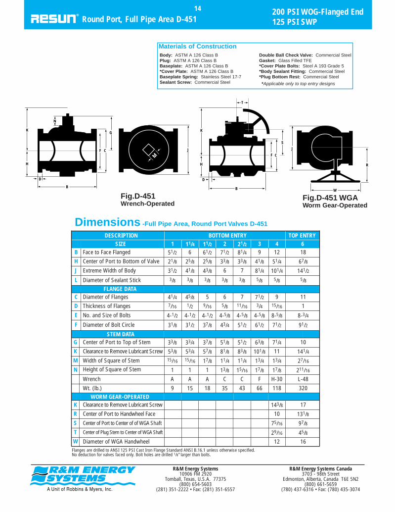
Standard Flow Plans
R&M Energy Systems10906 FM 2920
Tomball, Texas, U.S.A. 77375(800) 654-5603
(281) 351-2222 • Fax: (281) 351-6557
R&M Energy Systems Canada3703 - 98th Street
Edmonton, Alberta, Canada T6E 5N2(800) 661-5659
(780) 437-6316 • Fax: (780) 435-3074
3-Way/2-Port, 180° Turn
FLOW PLAN 114-Way, 4-Port; 90º Turn, 2 Positions
RESUN multi-port valves come in 3-way/2-port, 3-way/3-port, and 4-way/4-port types. They are manufac-tured in the full pipe area, rectangular port design in acomplete range of sizes, from 1/2" through 12".
Round port valves are also available in a limited num-
ber of sizes. Details available on request. Transflo plugshave wider than standard ports to prevent cut-off betweenflow positions (See page 28). Special configurations suchas 3-way/4-port, 4-way/2-port and 4-way/3-port are avail-able. Consult factory.
Standard Sizes and Types
Flow Plans17
Multi-Port Valves
FLOW PLAN 13-Way, 3-Port; 180º Turn, 3 Positions
FLOW PLAN 23-Way, 3-Port; 180º Turn, 3 Positions
FLOW PLAN 33-Way, 3-Port; 180º Turn, 3 Positions
FLOW PLAN 43-Way, 3-Port; 180º Turn, 3 Positions
FLOW PLAN 53-Way, 3-Port; 90º Turn, 2 Positions
FLOW PLAN 63-Way, 3-Port; 90º Turn, 2 Positions
FLOW PLAN 73-Way, 3-Port; 90º Turn, 2 Positions
FLOW PLAN 83-Way, 3-Port; 90º Turn, 2 Positions
FLOW PLAN 103-Way, 2-Port; 90º Turn, 2 Positions
FLOW PLAN 12
POSITION 1 POSITION 2
POSITION 1 POSITION 2 POSITION 1 POSITION 2
POSITION 1 POSITION 2
POSITION 1 POSITION 2POSITION 1 POSITION 2
POSITION 3
POSITION 1 POSITION 2 POSITION 3 POSITION 1 POSITION 2 POSITION 3
POSITION 1 POSITION 2 POSITION 3POSITION 1 POSITION 2 POSITION 3
POSITION 1 POSITION 2 POSITION 3POSITION 1 POSITION 2 POSITION 3
POSITION 4
FLOW PLAN 13
FLOW PLAN 93-Way, 3-Port; Without Stop Ring, 4 Positions
POSITION 1 POSITION 2

R&M Energy Systems10906 FM 2920
Tomball, Texas, U.S.A. 77375(800) 654-5603
(281) 351-2222 • Fax: (281) 351-6557
R&M Energy Systems Canada3703 - 98th Street
Edmonton, Alberta, Canada T6E 5N2(800) 661-5659
(780) 437-6316 • Fax: (780) 435-3074
Fig. D-951/D-953400 PSI WOG800 PSI TEST - 250 PSI SWP21/2" - 3" Sizes
Fig. D-951/D-953200 PSI WOG400 PSI TEST - 125 PSI SWP21/2" - 3" Sizes
200/400 PSI WOG-Threaded End18
3-Way Rectangular Port, Full Pipe Area D-951/3
Dimensions -Multi-Port Full Pipe Area Valves (3-Way Valves) D-951, D-953
SIZE 1/2
End to EndA 35/8
Center of Port to Bottom of StemH 21/8
Center of Port to Top of StemG 33/8Clearance to Remove Lubricant ScrewK 53/8
Width of Square of StemM 15/16
Diameter of Sealant StickL 3/8
Wrench AHeight of Square of StemN 11/8
Weight (lbs.) 5
3/4
35/8
21/8
33/853/815/16
3/8
A11/8
5
1
43/8
25/8
31/251/215/16
3/8
A11/8
8
11/4
53/4
31/4
41/461/415/16
3/8
A11/8
15
11/2
53/4
31/4
41/461/415/16
3/8
A11/8
15
2
63/431/2
55/883/8
11/4
3/8
C13/8
24
STEM DATA
21/2
71/241/8
57/887/8
11/4
3/8
C13/8
35
3
81/451/4
71/2111/4
13/4
5/8
F17/8
57
DESCRIPTION BOTTOM ENTRY
G
H
A
N
K
M
Body: ASTM A 126 Class BPlug: ASTM A 126 Class BBaseplate: ASTM A 126 Class BBaseplate Spring: Stainless Steel 17-7
Sealant Screw: Commercial SteelDouble Ball Check Valve: CommercialSteelGasket: Glass Filled TFE
Materials of Construction

WORM GEAR-OPERATED
STEM DATA
FLANGE DATA
R&M Energy Systems10906 FM 2920
Tomball, Texas, U.S.A. 77375(800) 654-5603
(281) 351-2222 • Fax: (281) 351-6557
R&M Energy Systems Canada3703 - 98th Street
Edmonton, Alberta, Canada T6E 5N2(800) 661-5659
(780) 437-6316 • Fax: (780) 435-3074
200PSI WOG-Flanged End19
3-Way Rec. Port, Full Pipe Area D-952/D-954
DESCRIPTION BOTTOM ENTRY TOP ENTRYSIZE 21/2 31 11/2 2 4 5 6 8
Face to Face FlangedB 9 10 111/261/2 14 14 17 20
Center of Port to Bottom of ValveH 31/2 41/8 51/425/8 31/4 6 73/8 81/2 101/4
Diameter of Sealant StickL 3/8 3/8 5/83/8 3/8 5/8 5/8 5/8 5/8
63/4
Diameter of FlangesC 6 7 71/241/4 9 10 11 131/2Thickness of FlangesD 5/8 11/16 3/47/16 9/16 15/16 15/16 1 11/8
Diameter of Bolt CircleF 43/4 51/2 631/2 37/8 71/2 81/2 91/2 113/4
No. and Size of BoltsE 4-5/8 4-5/8 4-5/84-1/2 4-1/2 8-5/8 8-3/4 8-3/4 8-3/4
5
Center of Port to Top of StemG 53/8 57/8 71/231/2 81/2 93/8 12 147/8Clearance to Remove Lubricant ScrewK 83/8 87/8 111/451/2 61/4 121/4 131/8 161/4 191/8
Wt. (lb.) 38 52 8412 20 152 215 412 691
Height of Square of StemN 13/8 13/8 17/811/8 11/8 2 2 3 35/8
Width of Square of StemM 11/4 1 13/415/16 15/16 13/4 13/4 27/16 3
Wrench C C FA A H-30 H-36 L-48 M-60
41/4
Clearance to Remove Lubricant ScrewK 151/2 167/16 191/16 2115/16
Center of Port to Handwheel FaceR 101/8 101/8 131/8 131/8
Center of Plug Stem to Center of WGA ShaftT 29/16 31/8 45/8 411/16
Center of Port to Center of of WGA ShaftS 81/16 91/2 1113/16 143/8
Diameter of WGA HandwheelW 12 16 16 16
Dimensions -Multi-Port Full Pipe Area Valves (3-Way Valves) D-952, D-954
*Any multi-port with WGA and 180˚ or 360˚ rotation will require a Special Gear. Consult factory for pricing.
N
H
K M
G
CF
BD
H
K
S
CF
B
D
T
W
1/2 of Bdimension
R
Body: ASTM A 126 Class BPlug: ASTM A 126 Class BBaseplate: ASTM A 126 Class B*Cover Plate: ASTM A 126 Class BBaseplate Spring: Stainless Steel17-7Sealant Screw: Commercial SteelDouble Ball Check Valve:Commercial SteelGasket: Glass Filled TFE
*Cover Plate Bolts: Steel A 193Grade B5*Body Sealant Fitting:Commercial Steel*Plug Bottom Rest: CommercialSteel
*Applicable only to top entrydesigns
Materials of Construction
Flanges are drilled to ANSI 125 PSI Cast Iron Flange Standard ANSI B.16.1 unless otherwisespecified. No deduction for valves faced only. Bolt holes are drilled 1/8" larger than bolts.
Fig. D-95290˚ Turn, 3-way/2-port200 PSI WOG400 PSI TEST - 125 PSI SWP1" - 8" Sizes, Wrench Operated Flow Plan 10
Fig. D-952180˚ Turn, 3-way/2-port200 PSI WOG400 PSI TEST - 125 PSI SWP1" - 8" Sizes, Wrench OperatedFlow Plans 12, 13
Fig. D-952 WGA90˚ Turn, 3-way/2-port200 PSI WOG400 PSI TEST - 125 PSI SWP4" - 8" Sizes, Worm Gear-OperatedFlow Plan 10
Fig. D-952 WGA180˚ Turn, 3-way/2-port*200 PSI WOG400 PSI TEST - 125 PSI SWPFlow Plans 12, 13
Fig. D-95490˚ Turn, 3-way/3-port200 PSI WOG400 PSI TEST - 125 PSI SWP1" - 8" Sizes, Wrench OperatedFlow Plans 5,6,7,8
Fig. D-954 WGA90˚ Turn, 3-way/3-port200 PSI WOG400 PSI TEST - 125 PSI SWP4" - 8" Sizes, Worm Gear-OperatedFlow Plans 5,6,7,8
Fig. D-954180˚ Turn, 3-way/3-port*200 PSI WOG400 PSI TEST - 125 PSI SWP1" - 8" Sizes, Wrench OperatedFlow Plans 1,2,3,4
Fig. D-954 WGA180˚ Turn, 3-way/3-port*200 PSI WOG400 PSI TEST - 125 PSI SWP4" - 8" Sizes, Worm Gear-OperatedFlow Plans 1,2,3,4
Fig. D-954360˚ Turn, 3-way/3-port*200 PSI WOG400 PSI TEST - 125 PSI SWP1" - 8" Sizes, Wrench OperatedFlow Plan 9
Fig. D-954 WGA360˚ Turn, 3-way/3-port*200 PSI WOG400 PSI TEST - 125 PSI SWP4" - 8" Sizes, Worm Gear-OperatedFlow Plan 9

R&M Energy Systems10906 FM 2920
Tomball, Texas, U.S.A. 77375(800) 654-5603
(281) 351-2222 • Fax: (281) 351-6557
R&M Energy Systems Canada3703 - 98th Street
Edmonton, Alberta, Canada T6E 5N2(800) 661-5659
(780) 437-6316 • Fax: (780) 435-3074
Fig. D-96190˚ Turn, 4-way/4-port400 PSI WOG800 PSI TEST - 250 PSI SWP21/2" - 3" Sizes, Flow Plan 11
Fig. D-96190˚ Turn, 4-way/4-port200 PSI WOG400 PSI TEST - 125 PSI SWP21/2" - 3" Sizes, Flow Plan 11
200/400 PSI WOG-Threaded End20
4-Way Rectangular Port, Full Pipe Area D-961
Dimensions -Multi-Port Full Pipe Area Valves (4-Way Valves) D-961
SIZE 1/2
End to EndA 35/8
Center of Port to Bottom of StemH 21/8
Center of Port to Top of StemG 33/8Clearance to Remove Lubricant ScrewK 53/8
Width of Square of StemM 15/16
Diameter of Sealant StickL 3/8
Wrench AHeight of Square of StemN 11/8
Weight (lbs.) 51/2
3/4
35/8
21/8
33/853/815/16
3/8
A11/8
51/2
1
43/8
25/8
31/251/215/16
3/8
A11/8
9
11/4
53/4
31/4
41/461/415/16
3/8
A11/8
16
11/2
53/4
31/4
41/461/415/16
3/8
A11/8
16
2
63/431/2
55/883/8
11/4
3/8
C13/8
25
STEM DATA
21/2
71/241/8
57/887/8
11/4
3/8
C13/8
35
3
81/451/4
71/2111/4
13/4
5/8
F-1817/8
58
DESCRIPTION BOTTOM ENTRY
G
H
A
N
K
M
Body: ASTM A 126 Class BPlug: ASTM A 126 Class BBaseplate: ASTM A 126 Class BBaseplate Spring: Stainless Steel 17-7
Sealant Screw: Commercial SteelDouble Ball Check Valve: Commercial SteelGasket: Glass Filled TFE
Materials of Construction

DESCRIPTION BOTTOM ENTRY TOP ENTRY
200 PSI WOG-Flanged End21
4-Way Rectangular Port, Full Pipe Area D-962
SIZE 21/2 311/2 2 4 6 8Face to Face FlangedB 9 10 111/2 14 17 20
Center of Port to Bottom of ValveH 31/2 41/8 51/431/4 6 81/2 101/4
Diameter of Sealant StickL 3/8 3/8 5/83/8 5/8 5/8 5/8
63/4
FLANGE DATADiameter of FlangesC 6 7 71/2 9 11 131/2Thickness of FlangesD 5/8 11/16 3/49/16 15/16 1 11/8
Diameter of Bolt CircleF 43/4 51/2 637/8 71/2 91/2 113/4
No. and Size of BoltsE 4-5/8 4-5/8 4-5/84-1/2 8-5/8 8-3/4 8-3/4
5
STEM DATACenter of Port to Top of StemG 53/8 57/8 71/2 81/2 12 147/8Clearance to Remove Lubricant ScrewK 83/8 87/8 111/461/4 121/4 161/4 191/8
Wt. (lb.) 44 58 9324 172 401 698
Height of Square of StemN 13/8 13/8 17/811/8 2 3 35/8
Width of Square of StemM 11/4 11/4 13/415/16 13/4 27/16 3
Wrench C C FA H-30 L-48 M-60
41/4
WORM GEAR-OPERATEDClearance to Remove Lubricant ScrewK 151/2 191/16 207/16
Center of Port to Handwheel FaceR 101/8 131/8 161/8
Center of Plug Stem to Center of WGA ShaftT 29/16 45/8 411/16
Center of Port to Center of of WGA ShaftS 81/16 1115/16 143/8
Diameter of WGA HandwheelW 12 16 16Flanges are drilled to ANSI 125 PSI Cast Iron Flange Standard ANSI B.16.1 unless otherwise specified.No deduction for valves faced only. Bolt holes are drilled 1/8" larger than bolts.
Dimensions -Multi-Port Full Pipe Area Valves (4-Way Valves) D-962
N
H
K M
G
CF
BD
H
K
S
CF
B
D
T
W
R
Fig. D-96290˚ Turn, 4-way/4-port200 PSI WOG400 PSI TEST - 125 PSI SWP11⁄2" - 8" Sizes, Wrench-OperatedFlow Plan 11
Fig. D-962 WGA90˚ Turn, 4-way/4-port200 PSI WOG400 PSI TEST - 125 PSI SWP4" - 8" Sizes, Worm Gear-Operated Flow Plan 11
Body: ASTM A 126 Class BPlug: ASTM A 126 Class BBaseplate: ASTM A 126 Class B*Cover Plate: ASTM A 126 Class BBaseplate Spring: Stainless Steel 17-7Sealant Screw: Commercial Steel
Double Ball Check Valve: Commercial SteelGasket: Glass Filled TFE*Cover Plate Bolts: Steel A 193 Grade 5*Body Sealant Fitting: Commercial Steel*Plug Bottom Rest: Commercial Steel
*Applicable only to top entry designs
Materials of Construction
R&M Energy Systems Canada3703 - 98th Street
Edmonton, Alberta, Canada T6E 5N2(800) 661-5659
(780) 437-6316 • Fax: (780) 435-3074
R&M Energy Systems10906 FM 2920
Tomball, Texas, U.S.A. 77375(800) 654-5603
(281) 351-2222 • Fax: (281) 351-6557

Transflo plugs, which have wider-than-standard ports to pre-vent cut-off between flow positions, are available for 3-way/2-port and 3-way/3-port valves in all flow plans. To order, specifyTransflo plug, in addition to usual ordering information.
Transflo Plugs
Transflo Plugs22
Speciality Plugs
Transflo, 3-Way/2-Port
POSITION 1 TURNING POSITION 2
POSITION 1 TURNING TURNINGPOSITION 2 POSITION 3
Transflo, 3-Way/3-Port
POSITION 2 TURNING POSITION 1
Transflo, 4-Way/4-Port
R&M Energy Systems Canada3703 - 98th Street
Edmonton, Alberta, Canada T6E 5N2(800) 661-5659
(780) 437-6316 • Fax: (780) 435-3074
R&M Energy Systems10906 FM 2920
Tomball, Texas, U.S.A. 77375(800) 654-5603
(281) 351-2222 • Fax: (281) 351-6557

The proportioning plug is a quarter-section plug atthe level of the body ports, but of full round constructionabove and below the ports. The quarter-section designpermits flow to be proportioned between two outlets.The proportioning plug turns 90˚. It is available for all
3-way valves in either right-hand or left-hand construc-tion. To order, specify valve size, pressure, end connec-tion, method of operation and right-hand or left-handproportioning plug.
Proportioning Plugs
Proportioning Valves23
Speciality Plugs
Proportioning Plug, Right-HandFlow Plan 7
NORMAL OPERATING POSITION MIXING POSITION BYPASS POSITION
Proportioning Plug, Left-HandFlow Plan 5
NORMAL OPERATING POSITION MIXING POSITION BYPASS POSITION
INLET
INLET
R&M Energy Systems Canada3703 - 98th Street
Edmonton, Alberta, Canada T6E 5N2(800) 661-5659
(780) 437-6316 • Fax: (780) 435-3074
R&M Energy Systems10906 FM 2920
Tomball, Texas, U.S.A. 77375(800) 654-5603
(281) 351-2222 • Fax: (281) 351-6557

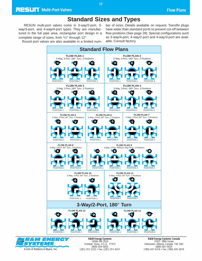
RESUN steam-jacket baseplates permit a constant supply ofsteam or hot oil to be circulated to maintain viscous substancessuch as asphalt, tar, paste, chocolate or wax at flowing consis-tency. The large area baseplate conducts heat with maximumefficiency, yet is lighter and requires less space than a sidejacket and is available for all standard valves including multi-ports. To order, specify size and figure number of standardvalve and add “WITH STEAM-JACKET BASEPLATE.” Whenvalves are ordered complete with steam-jacketed baseplates,please specify the application.
Steam-Jacketed Baseplate Valves24
Lubricated Plug Valves
Regular Opening and Venturi(see Valve Detail - pgs. 8-12, 18)
— — 4 4 — 4 4 4 4 — 43/4 43/4 43/4 71/8 71/8 71/8OD of Steam-Jacket Baseplate
— — 315/16 — 31/4 41/2 51/8 515/16 — 61/8 7 7 75/16 83/4 1013/16Center of Port to Bottom of Valve
— — 1/2 1/2 — 1/2 1/2 1/2 1/2 — 1/2 1/2 1/2 3/4 3/4 3/4Pipe Thread
D
H
C
D
H
C
D
H
C
D
H
2 2 2 2 2 2 2 2 21/2 21/2 21/2 31/2 31/2 — — —Distance between Pipe Taps
4 4 4 4 4 4 4 4 43/4 43/4 43/4 71/8 71/8 — — —OD of Steam-Jacket Baseplate
315/16 315/16 315/16 41/4 41/2 41/4 43/4 55/16 61/8 63/4 7 75/16 79/16 — — —Center of Port to Bottom of Valve
1/2 1/2 1/2 1/2 1/2 1/2 1/2 1/2 1/2 1/2 1/2 3/4 3/4Pipe Thread
2 2 2 2 2 2 21/2 21/2 21/2 — 31/2 — — — — —Distance between Pipe Taps
4 4 4 4 4 4 43/4 43/4 43/4 — 71/8 — — — — —OD of Steam-Jacket Baseplate
315/16 315/16 41/8 49/16 49/16 45/8 53/16 51/2 57/8 — — — — — —Center of Port to Bottom of Valve
1/2 1/2 1/2 1/2 1/2 1/2 1/2 1/2 1/2 — 3/4Pipe Thread
2 2 2 2 — 2 2 21/2 21/2 — 31/2 31/2 — —Distance between Pipe Taps
4 4 4 4 — 4 4 43/4 43/4 — 71/8 71/8 — —OD of Steam-Jacket Baseplate
31/4 31/4 47/16 55/16 — 55/16 59/16 61/16 71/8 — 71/4 8 — —Center of Port to Bottom of Valve
1/2 1/2 1/2 1/2 — 1/2 1/2 1/2 1/2 — 3/4 3/4 — —Pipe Thread
11/4THD
11/4FLG
11/2 2 21/2 3 31/2 4 6 8 10 12*5
C — — 2 2 — 2 2 2 2 — 21/2 21/2 21/2 31/2 31/2 31/2Distance between Pipe Taps
315/16
Full Pipe Area, 200 & 400 PSI(see Valve Detail - pgs. 13-17)
Multi-Port(see Valve Detail - pgs. 24-27)
Round Port(see Valve Detail - pgs. 19-20)
511/16
*Regular Opening†Add weight of Standard Valve to obtain total weight of Steam-Jacketed Valve.
1/2 3/4 1
R&M Energy Systems Canada3703 - 98th Street
Edmonton, Alberta, Canada T6E 5N2(800) 661-5659
(780) 437-6316 • Fax: (780) 435-3074
R&M Energy Systems10906 FM 2920
Tomball, Texas, U.S.A. 77375(800) 654-5603
(281) 351-2222 • Fax: (281) 351-6557
DESCRIPTION
Steam-Jacketed Baseplate Valves25
Lubricated Plug Valves
DESCRIPTION121086Full Pipe Area, Short Pattern
(see Valve Detail - pgs. 8-12, 18)C 6 6 6Distance Between Pipe TapsD 97/8 97/8 97/8OD of Steam-Jacket Baseplate
H 113/4 135/8 145/8Center of Port to Bottom of Valve3/4 3/4 3/4Pipe Thread
35+ 35+ 35+Wt. (lb.) +
C 6 6 6Distance Between Pipe TapsD 97/8 12 12OD of Steam-Jacket Baseplate
H 12 143/8 153/4Center of Port to Bottom of Valve3/4 3/4 3/4Pipe Thread
35+ 50+ 50+Wt. (lb.) +
C 6 6Distance Between Pipe TapsD 97/8 12OD of Steam-Jacket Baseplate
H 95/8 113/8Center of Port to Bottom of Valve3/4 3/4Pipe Thread
35+ 50+Wt. (lb.) +
C 6 6Distance Between Pipe TapsD 97/8 12OD of Steam-Jacket Baseplate
H 111/8 113/4Center of Port to Bottom of Valve3/4 3/4Pipe Thread
35+ 50+Wt. (lb.) +
*Regular opening only
Full Pipe Area(see Valve Detail - pgs. 13-17)
Round Port(see Valve Detail - pgs. 19-20)
Multi-Port(see Valve Detail - pgs. 24-27)
H
D
C
H
D
C
R&M Energy Systems Canada3703 - 98th Street
Edmonton, Alberta, Canada T6E 5N2(800) 661-5659
(780) 437-6316 • Fax: (780) 435-3074
R&M Energy Systems10906 FM 2920
Tomball, Texas, U.S.A. 77375(800) 654-5603
(281) 351-2222 • Fax: (281) 351-6557

Dial indicators, pointers and memory stops for balancingare available on regular opening, 1" through 8" and fullarea valves, 1/2" through 6".
To order a valve with dial indicator, pointer and memorystop, add “WITH DIAL INDICATOR, POINTER AND MEM-ORY STOP,” to other required valve components.
Dial Indicators, Pointers andMemory Stop Accessories
Dial Indicators, Pointers, Memory Stops26
Lubricated Plug Valves
R&M Energy Systems Canada3703 - 98th Street
Edmonton, Alberta, Canada T6E 5N2(800) 661-5659
(780) 437-6316 • Fax: (780) 435-3074
R&M Energy Systems10906 FM 2920
Tomball, Texas, U.S.A. 77375(800) 654-5603
(281) 351-2222 • Fax: (281) 351-6557

AB
D
M
Standard types A, C and F are one-piecewrenches for valve sizes up to and including 3" fullpipe area. One way wrenches are designed to fitthe valve in only one position. Handle not fur-nished unless specified.
To order wrenches, please furnish the appropri-ate information from this catalog section. Consultdimensions table to find the standard wrench des-ignation (A, C, F, H, etc.) for your valve.
Standard and One-Way
Wrenches27
Wrenches and Accessories
STANDARD WRENCH-HEAD FOR SIZES OVER 3 INCHES
Type H K L M
Wrench Head
Wt. (lb.) 41/2 81/2 71/2 20
BEffective Wrench HeadLength (Inches)
51/2 67/8 63/4 91/4
M Wrench Square 113/16 21/32 217/32 33/32
Standard Lengths Available
AEffective Wrench Length 24, 30, 24, 30,
48 48, 60, 72(Inches) 36 36, 48, 60
Diameter of Wrench Handle1 Cold 111/16 111/16 129/32
DHandle
Rolled (11/4 Std. (11/4 Std. (11/2 Std.
Steel Pipe) Pipe) Pipe)
STANDARD AND ONE-WAY
Standard A C F
One-Way A1 C1 F1
Wt. (lb.) 1 2 41/2
A Effective Wrench Length (Inches) 7 12 18
M Wrench Square 31/32 19/32 125/32
A
M
A
M
R&M Energy Systems Canada3703 - 98th Street
Edmonton, Alberta, Canada T6E 5N2(800) 661-5659
(780) 437-6316 • Fax: (780) 435-3074
R&M Energy Systems10906 FM 2920
Tomball, Texas, U.S.A. 77375(800) 654-5603
(281) 351-2222 • Fax: (281) 351-6557

Designed for locking and sealing in either open orclosed position. On removal of lock or seal, valve isoperated without removal of wrench. These are forstraightway valves only. (For multi-ports, use a lock-ing/sealing device.)
Standard Lock Wrenches
Wrenches28
Wrenches and Accessories
STANDARD LOCK WRENCHES
Type A-3* C-3* F-3* H-3**
Wrench Head
Wt. (lb.) 11/2 3 6 61/2
BEffective Wrench HeadLength (Inches)
51/2
M Wrench Square 31/32 19/16 125/32 125/32
Standard Lengths Available
AEffective Wrench Length(Inches)
7 12 18 24, 30, 36
Diameter of Wrench 1 Cold
DHandle
Rolled
Steel
* For same valves as standard wrenches A, C, F respectively.**For same valves as standard wrench H.
AB
D
M
A
M
R&M Energy Systems Canada3703 - 98th Street
Edmonton, Alberta, Canada T6E 5N2(800) 661-5659
(780) 437-6316 • Fax: (780) 435-3074
R&M Energy Systems10906 FM 2920
Tomball, Texas, U.S.A. 77375(800) 654-5603
(281) 351-2222 • Fax: (281) 351-6557
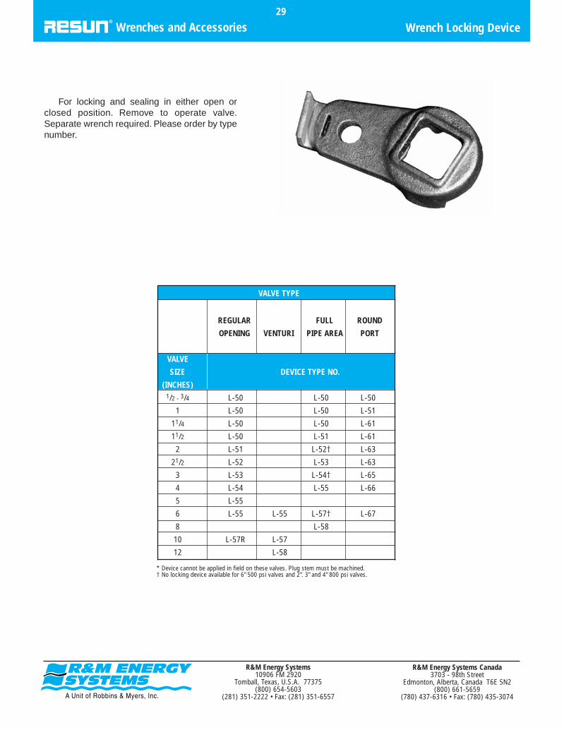
For locking and sealing in either open orclosed position. Remove to operate valve.Separate wrench required. Please order by typenumber.
Wrench Locking Device29
Wrenches and Accessories
* Device cannot be applied in field on these valves. Plug stem must be machined.† No locking device available for 6" 500 psi valves and 2". 3" and 4" 800 psi valves.
REGULAR FULL ROUND
OPENING VENTURI PIPE AREA PORT
VALVE
SIZE DEVICE TYPE NO.
(INCHES)1/2 - 3/4 L-50 L-50 L-50
1 L-50 L-50 L-51
11/4 L-50 L-50 L-61
11/2 L-50 L-51 L-61
2 L-51 L-52† L-63
21/2 L-52 L-53 L-63
3 L-53 L-54† L-65
4 L-54 L-55 L-66
5 L-55
6 L-55 L-55 L-57† L-67
8 L-58
10 L-57R L-57
12 L-58
R&M Energy Systems Canada3703 - 98th Street
Edmonton, Alberta, Canada T6E 5N2(800) 661-5659
(780) 437-6316 • Fax: (780) 435-3074
VALVE TYPE
R&M Energy Systems10906 FM 2920
Tomball, Texas, U.S.A. 77375(800) 654-5603
(281) 351-2222 • Fax: (281) 351-6557

Double-locking wrench has heavy-duty stops whichprevent accidental operation when wrench is properlypositioned and locked. The wrench is used for lockingand sealing in either open or closed position. Wrench is
removed and turned over to operate valve. Available forregular opening valves through 4", most full pipe areavalves through 3". Please order by type number.
“Texas-Style” Locking Wrench30
Wrenches and Accessories
“TEXAS-STYLE” LOCKING WRENCH
Wrench Type No. A-4 A-41 C-4 C-41 F-4
Regular Opening – Valve Size 1, 11/4, 11/2 2 21/2 3 4
Full Pipe Area – Valve Size 1/2, 3/4, 1, 11/4 11/4, 11/2 2 21/2 3, 4
Working Pressure PSI WOG 200, 400 200, 400, 500 200, 400, 500 200, 400, 500 200, 400
Wt. (lb.) 11/2 11/2 3 3 6
A–Effective Wrench Length (inches) 7 7 12 12 18
M–Wrench Square 31/32 31/32 19/32 19/32 125/32
A
M
Operating ValvePadlocked
Not available for D-450 or D-451.
R&M Energy Systems Canada3703 - 98th Street
Edmonton, Alberta, Canada T6E 5N2(800) 661-5659
(780) 437-6316 • Fax: (780) 435-3074
R&M Energy Systems10906 FM 2920
Tomball, Texas, U.S.A. 77375(800) 654-5603
(281) 351-2222 • Fax: (281) 351-6557
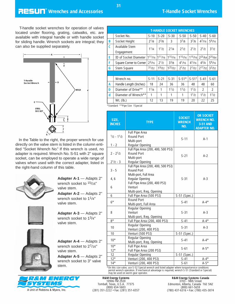
T-handle socket wrenches for operation of valveslocated under flooring, grating, catwalks, etc. areavailable with integral handle or with handle socketfor sliding handle. Wrench sockets are integral; theycan also be supplied separately.
In the Table to the right, the proper wrench for usedirectly on the valve stem is listed in the column enti-tled “Socket Wrench No.” If this wrench is used, noadapter is required. Wrench No. S-51 with 2" squaresocket, can be employed to operate a wide range ofvalves when used with the correct adapter, listed inthe right-hand column of this table.
T-Handle Socket Wrenches31
Wrenches and Accessories
SOCKETOR SOCKET
SIZE,TYPE WRENCH
WRENCH NO.INCHES
NO.3-51 AND
ADAPTER NO.Full Pipe Area
1/2 - 11/2 Round PortS-11 A-1Multi-port
1 - 2 Regular OpeningFull Pipe Area (200, 400, 500 PSI)
2 - 21/2 Round PortS-21 A-2Multi-port
21/2 - 3 Regular OpeningFull Pipe Area (200, 400, 500 PSI)
3 - 5 Round PortMulti-port, Full Area
4, 6 Regular Opening S-31 A-3Full Pipe Area (200, 400 PSI)
6 VenturiMulti-port, Reg. Opening
6 Full Pipe Area (500 PSI) S-51 (Spec.)
6*Round Port
S-41 A-4*Multi-port, Full AreaRegular Opening
8 Venturi S-31 A-3Multi-port, Reg. Opening
8* Full Pipe Area (200, 400 PSI) S-41 A-4*
10Regular Opening
S-31 A-3Venturi (200, 400 PSI)10 Venturi (500 PSI) S-51 (Spec.)
10*Regular Opening
S-41 A-4*Multi-port, Reg. Opening10* Full Pipe Area
S-61 A-5*12* Full Pipe Area (200 PSI)12 Regular Opening S-51 (Spec.)12* Venturi (200, 400 PSI) S-41 A-4*14* Venturi (200, 400 PSI) S-61 A-5*
*Standard **Pipe Size †Special
*On this size valve, use S-52 Special wrench and listed adapter where torque/service conditions permit wrench operation. If mechanical advantage is required, wrench S-51 (Standard or Special) may be used on worm gear operator.
T-HANDLE SOCKET WRENCHES
Socket No. S-10 S-20 S-30 S-50 S-50 S-40 S-60
B Socket Height 21/8 23/8 3 37/8 37/8 47/16 59/16
C Available Stem11/4 11/2 21/4 21/2 21/2 21/2 31/2
Engagement
E ID of Socket Diameter 111/16 111/16 115/16 115/16 115/16 225/64 225/64
F Square Corner to Corner 23/16 21/2 33/8 41/16 41/16 43/4 59/16
G Stem Square 31/32 19/32 125/32 21/32 21/32 217/32 33/32
Wrench no. S-11 S-21 S-31 S-51* S-51† S-41 S-61
A Handle Length (Inches) 18 24 36 36 48 48 60
D Diameter of Drive** 11/4 1 11/2 11/2 11/2 2 2
d Diameter of Wrench** 1 1 1 1 11/2 11/2 11/2
Wt. (lb.) 12 13 19 19 20 22 25
4'
C B
D
d
WELD
E
STEELSOCKET
F
G
A
T-HandleSocket Wrench
Adapter A-1 — Adapts 2"wrench socket to 15/16"valve stem.Adapter A-2 — Adapts 2"wrench socket to 11/4"valve stem.
Adapter A-3 — Adapts 2"wrench socket to 13/4"valve stem.
Adapter A-4 — Adapts 2"wrench socket to 27/16"valve stem.Adapter A-5 — Adapts 2"wrench socket to 3" valvestem.
R&M Energy Systems Canada3703 - 98th Street
Edmonton, Alberta, Canada T6E 5N2(800) 661-5659
(780) 437-6316 • Fax: (780) 435-3074
R&M Energy Systems10906 FM 2920
Tomball, Texas, U.S.A. 77375(800) 654-5603
(281) 351-2222 • Fax: (281) 351-6557

High head and low head extensions, fabricated to thecustomer’s requirements, facilitate the operation andservicing of RESUN wrench-operated valves installedunderground, beneath flooring, or in other locations difficult to access.
The high head extension consists of a tubular exten-sion which fits the operating stem and an extendedsealant screw. A standard wrench or T-handle socketwrench is applied to the top of the high head extensionto operate the valve.
The low head extension consists of an extendedsealant screw with sealant fitting. Valves using the lowhead extension are operated by a hollow T-handlesocket wrench which slips over the extended sealantscrew and fits a 2" square stem adapter attached to thevalve stem.
T-handle socket wrench is ordered separately (seepage 35.)
To order extensions:1. State figure number of valve.2. If valve is buried and protected by valve
box (illustration 1 and 3), state dimensionR, centerline of valve to groundline.
3. If valve is not buried, but is to be operated from above through a grating,from a platform, etc. (illustration 2) statedesired dimension S, centerline of valveto exact end of extension. Allow minimum clearance of 3" for sealant screw between extension and floor line.
High and low head extensions are shipped completely assembled. Required diameter of valve box shaft is 51/4". R&M Energy Systems does not supply valve boxes.
Dimension M = 2" square on all wrench-operated valves with stem square of 2" or smaller.27/16" square when valve stem is 27/16" square.
High and Low Head Extensions32
Wrenches and Accessories
3"
FLOORLINE
H
1. HIGH HEAD EXTENSION 2. HIGH HEAD EXTENSION 3. LOW HEAD EXTENSION HIGH HEAD LOW HEAD
R&M Energy Systems Canada3703 - 98th Street
Edmonton, Alberta, Canada T6E 5N2(800) 661-5659
(780) 437-6316 • Fax: (780) 435-3074
R&M Energy Systems10906 FM 2920
Tomball, Texas, U.S.A. 77375(800) 654-5603
(281) 351-2222 • Fax: (281) 351-6557

To facilitate gear operation of overhead valves, chain-wheels can be furnished. The design of RESUN chain-wheels permits easy installation or removal when valvesare already installed.
Coated lock link pattern chain is supplied with chain-wheel in the sizes shown. Use formula provided for cal-culating length of chain required.
To order a chainwheel:• With valve-specify valve figure number and add
“WITH WORM GEAR OPERATOR AND CHAINWHEEL.”• For valve already in service-specify chainwheel
and chain only and advise handwheel rim diameter.• State length of chain desired.
Formula for Estimating Chain Length for Worm Gear-Operated ValvesL=Chain length required.
H1=Distance from floor to centerline of valve.
S=Distance from centerline of valve to centerlineof worm gear shaft.
Chainwheel Size and NumberRESUN’s standard Chainwheel no. 4 has 22"
diameter and a 5/0 chain size. To estimate chainlength for worm gear-operated valves, use this for-mula: L=[(H1-4')+S]2+4'3"
Chainwheels for Gear-Operated Valves33
Wrenches and Accessories
*150 psi in 14" through 30" sizes.†1115/16" 4-way/4-port valves.
CHAINWHEEL DIMENSIONS
Valve Type Valve Size
4 5 6 8 10 12 14 16 18 20 24 30
Regular Opening S 7 7 715/16 103/8 131/4
Full Pipe Area,S 615/16 713/16 815/16 1211/16 149/16 1511/16
Short Pattern
Full Pipe Area,S 615/16 713/16 815/16 123/8 1411/16 1713/16 181/2 2015/16
Long Pattern, 200 PSI
Full Pipe Area,S 71/8 87/16 1013/16 139/16 1513/16 1615/16
Long Pattern, 400 PSI
Full Pipe Area,S 77/8 113/16
Long Pattern, 500 PSI
Venturi, 200* PSI S 7 77/8 9 1215/16 147/8 153/8 181/16 197/16 219/16 2315/16
Venturi, 400 PSI S 7 81/4 10 127/8 1413/16 157/8 171/4 185/8 203/4
Round Port S 75/16 9 97/8 1113/16 147/8 171/16
Multi-port, Full Area S 81/16 91/2 1113/16* 143/8 181/8 195/8
4"
H1
W1
S
R&M Energy Systems Canada3703 - 98th Street
Edmonton, Alberta, Canada T6E 5N2(800) 661-5659
(780) 437-6316 • Fax: (780) 435-3074
R&M Energy Systems10906 FM 2920
Tomball, Texas, U.S.A. 77375(800) 654-5603
(281) 351-2222 • Fax: (281) 351-6557

Sealants are shown by number, with service categories listed fortheir suitability. Numbers without suffix G are stick grade. Numberswith suffix G are gun grade, available in cartridges and bulk.
Specifications34
Sealant
SEALANTNUMBER
24
24-G
58
58-G
62
62-G
101
101-G
103
103-G
104
104-G
104W
104W-G
375
FORMSAVAILABLE
Sticks
Cartridgesor Bulk
Sticks
Cartridgesor Bulk
Sticks
Cartridgesor Bulk
Sticks
Cartridgesor Bulk
Sticks
Cartridgesor Bulk
Sticks
Cartridgesor Bulk
Sticks
Cartridgesor Bulk
Cartridgesor Bulk
TEMPERATURERANGE
0 to 250˚F
0 to 225˚F
0 to 385˚F
0 to 350˚F
-15 to 250˚F
-20 to 225˚F
-20 to 450˚F
-20 to 400˚F
0 to 450˚F
-20 to 400˚F
-15 to 250˚F
SUITABLE FOR
Aqueous solutions of alkalies, organic acids, salts, alco-hols, dyes, seawater, caustic and strong chemicals.
Petroleum fuels, oils and waxes, gasoline, kerosene,aviation and jet fuels, propylene, benzene, toluene,butadiene, xylene, styrene and cumene.
Natural and manufactured gas, air and non-corrosivegases. Sewage, sludge and cold water services. UL-approved.
Air and natural or manufactured gas, hot water, steamasphalt, tar or pitch. Salt solutions, ammonia liquors,strong chemicals, glycerine and glycols. Also useful forfood products, vegetable oils and fatty acids, *food andpharmaceutical applications as determined suitable byuser. Lowest operating torque at extremely low temp.
Special purpose sealant for natural gas service and gly-col dehydration units. Also suitable for liquid hydrocar-bons and aqueous solutions. Silicone free.
Multi-purpose sealant for petroleum solvents, fuels andoils, crude distillates, butane, propane, wet fuel gases,glycols, salt solutions and aqueous solutions. Natural ormanufactured and liquefied petroleum gases. Bestsealant at high pressure. Silicone free.
Same as 104 except thinner consistency for use in envi-ronments below +10˚ F. Will not seal as well as 104at higher temperatures.
Extra soft lubricant for freeing hard operating valves onwater and gas services. Resistant to water, dilute acidsand alkalies. Silicone free.
UNSUITABLE FOR
LiquidHydrocarbons
Strong AminesAlkalies
Air
LiquidHydrocarbons
LiquidHydrocarbons
Alcohols and Ketones
Strong AminesAlkalies
Air
same as 104
COLOR
Cream
Brown
Black
White
Tan
Green
Green
Black
*Food products should be determined satisfactory at the discretion of the user.
R&M Energy Systems Canada3703 - 98th Street
Edmonton, Alberta, Canada T6E 5N2(800) 661-5659
(780) 437-6316 • Fax: (780) 435-3074
R&M Energy Systems10906 FM 2920
Tomball, Texas, U.S.A. 77375(800) 654-5603
(281) 351-2222 • Fax: (281) 351-6557

This table is intended as a general indication of thechemical resistance of RESUN sealants and may be usedas a guide to sealant selection. Sealant specifications,page 41, should be consulted for high and low tempera-ture limitations of the suggested sealants and a moredetailed description of service categories.
In cases not covered by a recommendation, it is advis-able to contact your local RESUN representative or the
manufacturing plant in Tomball, Texas. When requestingsealant recommendations, please furnish the followinginformation:1. Size and description of valve2. Name or description of flow medium3. Operating temperature or high and low temperature4. Operating pressure5. Whether stick or gun injection is preferred
Absorption Oil..........................................Acetaldehyde............................................Acetate Solvents......................................Acetic Acid...............................................Acetic Anhydride......................................Acetone....................................................Acetylene Gas.........................................Acetylene Generator Waste.....................Acid Sludge..............................................Acrylonitrile...............................................Agitator Draw-off, Refinery.......................Air............................................................Alcohols Methyl or Ethyl..........................Alcohols Higher........................................Alkalies.....................................................Alums........................................................Aluminum Acetate....................................Aluminum Chloride, Anhydrous................Aluminum Resinate..................................Aluminum Sulfate.....................................Aluminum Salt Solutions..........................Ammonia Gas or Liquid...........................Ammonia Liquor.......................................Ammonia Recovery Lines........................Ammonia Saturators................................Ammonium Chloride.................................Ammonium Hydroxide..............................Ammonium Nitrate....................................Ammonium Phosphate.............................Ammonium Salt Solutions........................Ammonium Sulfate...................................Ammonium Sulfate Liquor........................Amyl Acetate............................................Amyl Alcohol.............................................Amyl Chloride...........................................Aniline......................................................Aniline Oils-Hydrocarbon..........................Aniline Oils-Aqueous................................Animal Oils...............................................Aqueous Solutions....................................Aromatic Solvents.....................................Arsenic Acid.............................................Arsenic Trichloride....................................Asphalt ....................................................Asphalt Emulsions....................................Asphalt Paints...........................................Barium Carbonate....................................Barium Chloride.......................................Barium Hydroxide.....................................Barium Salt Solutions...............................Barium Sulfate..........................................Barytes.....................................................Beer..........................................................Benzaldehyde (Tincture)..........................Benzaldehyde (Pure)...............................Benzene (Benzol).....................................Benzine (Petroleum Ether).......................Benzoate of Soda.....................................Benzoic Acid.............................................Bicarbonate of Soda.................................Bituminous Paints.....................................Black Liquor, Paper Industry.....................Blast Furnace Gas....................................Bleach Liquor (Calcium Hypochlorite)......Blood Plasma...........................................Blue Gas...................................................Boiler Blow-Off (Steam)...........................Boiler Feed Water.....................................
58, 103, 10458, 10358, 10324, 10124, 10124, 10124, 10324, 10124, 10158, 10358, 103, 10462, 10324, 10124, 10124, 10124, 10124, 10124, 10124, 10124, 10124, 10124, 10124, 10124, 10124, 10124, 10124, 10124, 10124, 10124, 10124, 10124, 10158, 10324, 10158, 10324,101,103,10458, 10324, 10158,101,103, 10424, 101, 10358, 10324, 10124, 10110110110124, 10124, 10124, 10124, 10124, 10124, 10124, 10124, 10110158, 10358, 10324, 10124, 10124, 10158, 103, 10424, 10162, 10124, 10110162, 10124, 10124, 101
SERVICE SEALANT NO.
Borax........................................................Boric Acid..................................................Brake Fluid................................................Bright Stock Petroleum.............................Brines........................................................Bulk Stations.............................................Bunker Oils (Fuel Oils).............................Butadiene..................................................Butane, Gas or Liquid...............................Butyric Acid...............................................Calcium Chloride......................................Calcium Hydroxide....................................Calcium Hypochlorite................................Calcium Salt Solutions..............................Calcium Sulfate.........................................Carbolic Acid (Phenol Solution)................Carbon Dioxide Gas or Liquid..................Carbon Disulfide.......................................Carbon Monoxide Gas..............................Carbon Tetrachloride................................Carbonic Acid (Carbon Dioxide Solution)...Casein Paints............................................Casing Head Gas.....................................Castor Oil..................................................Caustic Cell Liquors..................................Caustic Potash (Potassium Hydroxide)....Caustic Soda (Sodium Hydroxide)...........Cellosolve Solvents..................................Cellulose Acetate......................................Cement Slurries........................................Chestnut Extract.......................................Chlorinated Paraffin..................................Chlorinated Solvents.................................Chlorobenzene.........................................Chrome Tanning Solutions........................Chromic Acid............................................Citric Acid..................................................Clay Slips..................................................Coal Gas...................................................Coal Tar Oils.............................................Coal Tar Solvents.....................................Coal Washers...........................................Coconut Oil...............................................Coke Oven Gas........................................Condensate..............................................Continuous Treators, Refinery..................Copper Solution........................................Copper Sulfate..........................................Corn Oil.....................................................Corn Syrup(Glucose)................................Corrosive Gases.......................................Cottonseed Oil..........................................Creosote Oil..............................................Cresylic Acid (Cresol)...............................Crude Oil...................................................Crude Oil and Brine..................................Cumene....................................................Cutting Oils...............................................Cyanide Solutions.....................................Denatured Alcohol....................................Dextrin......................................................Dextrose...................................................Dichlorethylene.........................................Diesel Fuel................................................Diethanolamine.........................................Distillate, Petroleum..................................Doctor Solution (Sodium Plumbite)..........
24, 10124, 10124, 10158, 103, 10424, 10158, 103, 10458, 103, 10458, 103, 10458, 103, 1042424, 10124, 10124, 10124, 10124, 10124, 10162, 10110162, 10158, 10324, 10124, 10158, 103, 10424, 10124, 10124, 10124, 10158, 10358, 10324, 10124, 10158, 10358, 10358, 10324, 10124, 10124, 10124, 10162, 10158, 10358, 10324, 10110124, 10158, 103, 10458, 103, 10424, 10124, 10110124, 10124, 10110124, 10124, 10158, 103, 10458, 103, 10458, 10358, 103, 10424, 10124, 10124, 10124, 10158, 10358, 103, 10424, 10158, 103, 10424, 101
SERVICE SEALANT NO.
Doctor Solution and Gasoline...................Downtherm E...........................................Downtherm SR-1......................................Drilling Mud...............................................Drinking Water..........................................Drip Cocks Gas........................................Drip Oil......................................................Dry Cleaning Fluid....................................Dyes, Oil Soluble......................................Dyes, Water Soluble.................................Elaine Red Oil..........................................Electrolytic Cell Liquor..............................Emulsions.................................................Epoxies.....................................................Epsom Salts..............................................Ethane Gas...............................................Ethanolamine............................................Ethers.......................................................Ether Petroleum........................................Ethylene Oxide.........................................Ethyl Acetate.............................................Ethyl Alcohol (Ethanol).............................Ethyl Benzene...........................................Ethyl Chloride Gas or Liquid.....................Ethylene Dibromide..................................Ethylene Dichloride...................................Ethylene Gas............................................Ethylene Glycol.........................................Fatty Acids................................................Fatty Acids and Water...............................Ferric Chloride..........................................Ferric Nitrate.............................................Ferric Sulfate............................................Ferrous Chloride.......................................Ferrous Sulfate.........................................Fertilizer Solutions-Nitrate........................
Phosphate..............................Sulfate....................................
Filter House Lines.....................................Fish Oil......................................................Flavoring Extracts.....................................Flue Gas...................................................Fluosilic Acid.............................................Foamite Lines...........................................Food Products..........................................Formaldehyde...........................................Formic Acid...............................................Freon, Gas or Liquid.................................Fruit Juices...............................................Fuel Oil.....................................................Fuming Sulfuric Acid.................................Furfural.....................................................Fusel Oil (Crude Amyl Alcohol)................Gallic Acid.................................................Gas Drips..................................................Gas Fuel Lines.........................................Gas Liquor (Ammonia Liquor)..................Gas, Manufactured...................................Gas Lifts....................................................Gas, Natural..............................................Gas Odorizers...........................................Gas Oil......................................................Gasoline, Low Aromatic............................Gasoline, High Aromatic...........................Gelatin......................................................Gin............................................................Glacial Acetic Acid....................................Glauber’s Salt...........................................
58, 103, 10458, 103, 10458, 103, 10424, 10124, 10158, 103, 10458, 10358, 10358, 10324, 10110124, 10124, 10124, 10124, 10162, 101, 103, 10424, 10158, 10358, 103, 10458, 10358, 10324, 10158, 10358, 10358, 10358, 10324,62,101,103,10424, 10124, 10124, 10124, 10124, 10124, 10124, 10124, 10124, 10124, 10124, 101103, 10410124, 10124, 62, 10124, 10124, 10124, 10124, 10124, 10158, 103, 10424, 10158, 103, 10424, 10124, 10124, 10124, 10158, 103, 10424, 62, 101, 10324, 10162, 101, 103, 10458, 103, 10458, 103, 10410158, 10358, 103, 10458, 10324, 10124, 10124, 10124, 101
SERVICE SEALANT NO.
Selection Guide35
Sealant
NOTE: Bold type indicates recommended sealant considering chemical compatibility.For extreme pressures or temperatures, consult factory.
R&M Energy Systems Canada3703 - 98th Street
Edmonton, Alberta, Canada T6E 5N2(800) 661-5659
(780) 437-6316 • Fax: (780) 435-3074
R&M Energy Systems10906 FM 2920
Tomball, Texas, U.S.A. 77375(800) 654-5603
(281) 351-2222 • Fax: (281) 351-6557
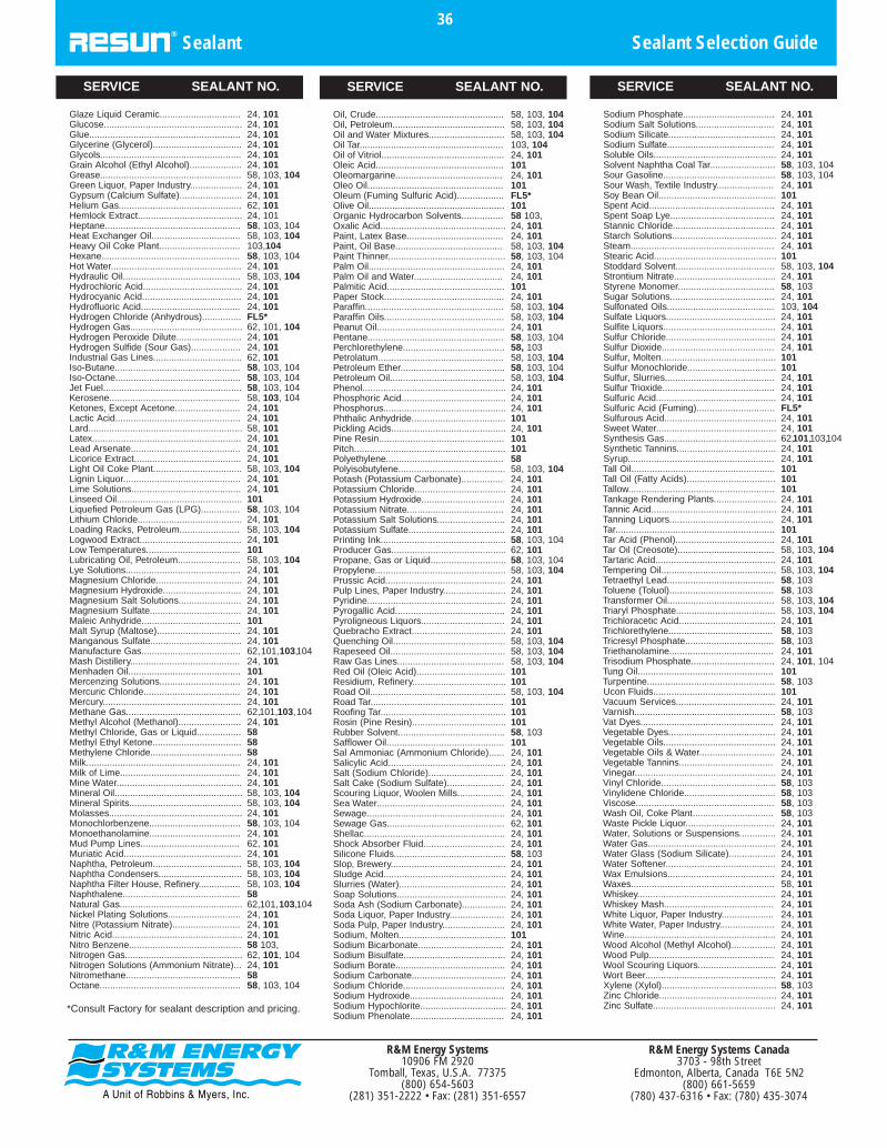
Glaze Liquid Ceramic...............................Glucose.....................................................Glue..........................................................Glycerine (Glycerol)..................................Glycols......................................................Grain Alcohol (Ethyl Alcohol)....................Grease......................................................Green Liquor, Paper Industry....................Gypsum (Calcium Sulfate)........................Helium Gas...............................................Hemlock Extract........................................Heptane....................................................Heat Exchanger Oil..................................Heavy Oil Coke Plant...............................Hexane.....................................................Hot Water..................................................Hydraulic Oil.............................................Hydrochloric Acid......................................Hydrocyanic Acid......................................Hydrofluoric Acid......................................Hydrogen Chloride (Anhydrous)...............Hydrogen Gas...........................................Hydrogen Peroxide Dilute.........................Hydrogen Sulfide (Sour Gas)...................Industrial Gas Lines..................................Iso-Butane................................................Iso-Octane................................................Jet Fuel.....................................................Kerosene..................................................Ketones, Except Acetone.........................Lactic Acid................................................Lard...........................................................Latex.........................................................Lead Arsenate..........................................Licorice Extract.........................................Light Oil Coke Plant..................................Lignin Liquor.............................................Lime Solutions..........................................Linseed Oil................................................Liquefied Petroleum Gas (LPG)...............Lithium Chloride........................................Loading Racks, Petroleum.......................Logwood Extract.......................................Low Temperatures....................................Lubricating Oil, Petroleum........................Lye Solutions............................................Magnesium Chloride.................................Magnesium Hydroxide..............................Magnesium Salt Solutions........................Magnesium Sulfate...................................Maleic Anhydride......................................Malt Syrup (Maltose)................................Manganous Sulfate...................................Manufacture Gas......................................Mash Distillery..........................................Menhaden Oil...........................................Mercenzing Solutions...............................Mercuric Chloride.....................................Mercury.....................................................Methane Gas............................................Methyl Alcohol (Methanol)........................Methyl Chloride, Gas or Liquid.................Methyl Ethyl Ketone..................................Methylene Chloride...................................Milk...........................................................Milk of Lime..............................................Mine Water................................................Mineral Oil.................................................Mineral Spirits...........................................Molasses...................................................Monochlorbenzene...................................Monoethanolamine...................................Mud Pump Lines......................................Muriatic Acid.............................................Naphtha, Petroleum..................................Naphtha Condensers................................Naphtha Filter House, Refinery................Naphthalene.............................................Natural Gas...............................................Nickel Plating Solutions............................Nitre (Potassium Nitrate)..........................Nitric Acid..................................................Nitro Benzene...........................................Nitrogen Gas.............................................Nitrogen Solutions (Ammonium Nitrate)...Nitromethane............................................Octane......................................................
24, 10124, 10124, 10124, 10124, 10124, 10158, 103, 10424, 10124, 10162, 10124, 10158, 103, 10458, 103, 104103,10458, 103, 10424, 10158, 103, 10424, 10124, 10124, 101FL5*62, 101, 10424, 10124, 10162, 10158, 103, 10458, 103, 10458, 103, 10458, 103, 10424, 10124, 10158, 10124, 10124, 10124, 10158, 103, 10424, 10124, 10110158, 103, 10424, 10158, 103, 10424, 10110158, 103, 10424, 10124, 10124, 10124, 10124, 10110124, 10124, 10162,101,103,10424, 10110124, 10124, 10124, 10162,101,103,10424, 10158585824, 10124, 10124, 10158, 103, 10458, 103, 10424, 10158, 103, 10424, 10162, 10124, 10158, 103, 10458, 103, 10458, 103, 1045862,101,103,10424, 10124, 10124, 10158 103,62, 101, 10424, 1015858, 103, 104
SERVICE SEALANT NO.
Oil, Crude.................................................Oil, Petroleum...........................................Oil and Water Mixtures.............................Oil Tar.......................................................Oil of Vitriol...............................................Oleic Acid.................................................Oleomargarine.........................................Oleo Oil....................................................Oleum (Fuming Sulfuric Acid)..................Olive Oil....................................................Organic Hydrocarbon Solvents................Oxalic Acid................................................Paint, Latex Base.....................................Paint, Oil Base.........................................Paint Thinner.............................................Palm Oil....................................................Palm Oil and Water..................................Palmitic Acid.............................................Paper Stock..............................................Paraffin.....................................................Paraffin Oils..............................................Peanut Oil.................................................Pentane....................................................Perchlorethylene.......................................Petrolatum................................................Petroleum Ether........................................Petroleum Oil............................................Phenol.......................................................Phosphoric Acid........................................Phosphorus...............................................Phthalic Anhydride....................................Pickling Acids............................................Pine Resin................................................Pitch..........................................................Polyethylene.............................................Polyisobutylene.........................................Potash (Potassium Carbonate)................Potassium Chloride...................................Potassium Hydroxide................................Potassium Nitrate.....................................Potassium Salt Solutions..........................Potassium Sulfate.....................................Printing Ink................................................Producer Gas............................................Propane, Gas or Liquid.............................Propylene..................................................Prussic Acid..............................................Pulp Lines, Paper Industry........................Pyridine.....................................................Pyrogallic Acid..........................................Pyroligneous Liquors................................Quebracho Extract....................................Quenching Oil...........................................Rapeseed Oil............................................Raw Gas Lines.........................................Red Oil (Oleic Acid)..................................Residium, Refinery....................................Road Oil....................................................Road Tar...................................................Roofing Tar................................................Rosin (Pine Resin)....................................Rubber Solvent.........................................Safflower Oil.............................................Sal Ammoniac (Ammonium Chloride)......Salicylic Acid.............................................Salt (Sodium Chloride).............................Salt Cake (Sodium Sulfate)......................Scouring Liquor, Woolen Mills..................Sea Water.................................................Sewage.....................................................Sewage Gas.............................................Shellac......................................................Shock Absorber Fluid...............................Silicone Fluids...........................................Slop, Brewery............................................Sludge Acid...............................................Slurries (Water).........................................Soap Solutions..........................................Soda Ash (Sodium Carbonate).................Soda Liquor, Paper Industry.....................Soda Pulp, Paper Industry........................Sodium, Molten.........................................Sodium Bicarbonate.................................Sodium Bisulfate.......................................Sodium Borate..........................................Sodium Carbonate....................................Sodium Chloride.......................................Sodium Hydroxide....................................Sodium Hypochlorite.................................Sodium Phenolate....................................
58, 103, 10458, 103, 10458, 103, 104103, 10424, 10110124, 101101FL5*10158 103,24, 10124, 10158, 103, 10458, 103, 10424, 10124, 10110124, 10158, 103, 10458, 103, 10424, 10158, 103, 10458, 10358, 103, 10458, 103, 10458, 103, 10424, 10124, 10124, 10110124, 1011011015858, 103, 10424, 10124, 10124, 10124, 10124, 10124, 10158, 103, 10462, 10158, 103, 10458, 103, 10424, 10124, 10124, 10124, 10124, 10124, 10158, 103, 10458, 103, 10458, 103, 10410110158, 103, 10410110110158, 10310124, 10124, 10124, 10124, 10124, 10124, 10124, 10162, 10124, 10124, 10158, 10324, 10124, 10124, 10124, 10124, 10124, 10124, 10110124, 10124, 10124, 10124, 10124, 10124, 10124, 10124, 101
SERVICE SEALANT NO.
Sodium Phosphate...................................Sodium Salt Solutions..............................Sodium Silicate.........................................Sodium Sulfate.........................................Soluble Oils...............................................Solvent Naphtha Coal Tar.........................Sour Gasoline...........................................Sour Wash, Textile Industry......................Soy Bean Oil.............................................Spent Acid................................................Spent Soap Lye........................................Stannic Chloride.......................................Starch Solutions........................................Steam.......................................................Stearic Acid...............................................Stoddard Solvent......................................Strontium Nitrate.......................................Styrene Monomer.....................................Sugar Solutions........................................Sulfonated Oils.........................................Sulfate Liquors..........................................Sulfite Liquors...........................................Sulfur Chloride..........................................Sulfur Dioxide...........................................Sulfur, Molten............................................Sulfur Monochloride..................................Sulfur, Slurries..........................................Sulfur Trioxide...........................................Sulfuric Acid..............................................Sulfuric Acid (Fuming)..............................Sulfurous Acid...........................................Sweet Water..............................................Synthesis Gas...........................................Synthetic Tannins......................................Syrup........................................................Tall Oil.......................................................Tall Oil (Fatty Acids)..................................Tallow........................................................Tankage Rendering Plants........................Tannic Acid................................................Tanning Liquors........................................Tar.............................................................Tar Acid (Phenol)......................................Tar Oil (Creosote).....................................Tartaric Acid..............................................Tempering Oil............................................Tetraethyl Lead.........................................Toluene (Toluol)........................................Transformer Oil.........................................Triaryl Phosphate......................................Trichloracetic Acid.....................................Trichlorethylene........................................Tricresyl Phosphate..................................Triethanolamine........................................Trisodium Phosphate................................Tung Oil....................................................Turpentine.................................................Ucon Fluids...............................................Vacuum Services......................................Varnish......................................................Vat Dyes...................................................Vegetable Dyes.........................................Vegetable Oils...........................................Vegetable Oils & Water.............................Vegetable Tannins....................................Vinegar......................................................Vinyl Chloride............................................Vinylidene Chloride...................................Viscose.....................................................Wash Oil, Coke Plant...............................Waste Pickle Liquor..................................Water, Solutions or Suspensions..............Water Gas.................................................Water Glass (Sodium Silicate)..................Water Softener..........................................Wax Emulsions.........................................Waxes.......................................................Whiskey.....................................................Whiskey Mash..........................................White Liquor, Paper Industry....................White Water, Paper Industry.....................Wine..........................................................Wood Alcohol (Methyl Alcohol).................Wood Pulp................................................Wool Scouring Liquors..............................Wort Beer..................................................Xylene (Xylol)............................................Zinc Chloride.............................................Zinc Sulfate...............................................
24, 10124, 10124, 10124, 10124, 10158, 103, 10458, 103, 10424, 10110124, 10124, 10124, 10124, 10124, 10110158, 103, 10424, 10158, 10324, 101103, 10424, 10124, 10124, 10124, 10110110124, 10124, 10124, 101FL5*24, 10124, 10162,101,103,10424, 10124, 10110110110124, 10124, 10124, 10110124, 10158, 103, 10424, 10158, 103, 10458, 10358, 10358, 103, 10458, 103, 10424, 10158, 10358, 10324, 10124, 101, 10410158, 10310124, 10158, 10324, 10124, 10124, 10124, 10124, 10124, 10158, 10358, 10358, 10358, 10324, 10124, 10124, 10124, 10124, 10124, 10158, 10124, 10124, 10124, 10124, 10124, 10124, 10124, 10124, 10124, 10158, 10324, 10124, 101
SERVICE SEALANT NO.
*Consult Factory for sealant description and pricing.
Sealant Selection Guide36
Sealant
R&M Energy Systems Canada3703 - 98th Street
Edmonton, Alberta, Canada T6E 5N2(800) 661-5659
(780) 437-6316 • Fax: (780) 435-3074
R&M Energy Systems10906 FM 2920
Tomball, Texas, U.S.A. 77375(800) 654-5603
(281) 351-2222 • Fax: (281) 351-6557

High-quality RESUN plug valve sealants are formulatedfor specific ladings. Proper servicing procedure and useof the correct RESUN sealant for the application isessential if maximum operating efficiency and longestlife are to be obtained from your RESUN valves.
Stick and Gun Sealant InjectionRESUN sealants come in stick grade and gun grade.
Stick sealant injection is usually considered most con-venient with small numbers of valves or widely separated
valves. Grease gun servicing is standard for the largestsizes and may be preferred for smaller sizes if manyvalves are in service.
Stick grade is especially suitable for high pressure orhigh temperature services. If desired, these sealantscan be injected with a screw-primed grease gun. Stickgrade comes in sticks, gun sticks, and bulk.
Gun grade sealants are relatively soft, permitting easieroperation at low temperatures and with large valves.Gun grade comes in gun cartridges and in bulk.
GUN CARTRIDGE:141/2 oz. tube filled with gungrade sealant for use withGrease Gun No. 013867.Specify:1. Sealant number
(pages 41-43.include suffix G with number)
2. Size of cartridge3. Number of cartridges
BULK:1-pt., 1-qt., 1/2 gal., 1-gal.and 5-gal. cans. For usewith grease gun No.138047 or 013867.Specify:1. Sealant number
(pages 41-43.Include suffix G with number)
2. Size of can3. Number of cans
GUN STICKS:11/4" x 9", 4 per box.For use with greasegun No. 138047.Specify:1. Sealant number
(pages 41-43)2. Size of stick3. Number of boxes
STICKS:3/8", 1/2", 5/8" diameter, convenient lengths.Specify:1. Sealant number
(pages 41-43)2. Size of stick
(select from Bulletin LPM)
3. Number of boxes (SeeBulletin LPM for numberof sticks per box)
Sealant Forms and Injection Equipment
Combination Sealant Screw
The sealant screw, combined with giantbuttonhead fitting, is standard on RESUNplug valves allowing conversion from sticksealant injections to gun without installationof a separate fitting.
STANDARD (12" LONG)HOSE WITH BUTTONHEADCOUPLER
For use with grease gun.Part No. 135860
SCREW-PRIMED GREASE GUN
An extra heavy-duty lever gunfor both gun and stick gradesealants.Part No. 013867 (Hose extra)
MANUAL AVAILABLE ON REQUEST
Forms and Injection Equipment37
Sealant
Body Sealant Screw
New Style Old Style
Combination Sealant ScrewButtonhead Fitting
SPECIFY: 1. Part number2. Quantity
R&M Energy Systems Canada3703 - 98th Street
Edmonton, Alberta, Canada T6E 5N2(800) 661-5659
(780) 437-6316 • Fax: (780) 435-3074
R&M Energy Systems10906 FM 2920
Tomball, Texas, U.S.A. 77375(800) 654-5603
(281) 351-2222 • Fax: (281) 351-6557

All plug valves shall be of the lubricated plug type asmanufactured by R&M Energy Systems, or equal; valveson liquid sludge lines shall have full or nominal pipe sizearea ports. Port openings in straightway shall be eitherrectangular or round in shape. All multi-port valves shallbe of the rectangular port type, and shall have full or nom-inal pipe size area ports. Straightway valves to be used ongas lines may be of the reduced port (regular opening)type. Where these valves are used, those with the greatestport width are preferred for minimum turbulence andpressure drop. Plugs of all valves shall be of the cylindri-cal floating type. Contact between the plug, the line seatand the head seat is maintained by resilient pressure,through the sealant, the liquid or gas being transported,and/or the coil spring.
Valves shall be so constructed that excessive sealantpressure cannot be built up, but that the excessivesealant will be automatically and visibly discharged to theatmosphere around the neck of the plug when predeter-mined sealant pressures are exceeded.
For wrench-operated valves, at least one wrench is tobe supplied for each size and type, except where valvesare in convenient manifolds or groups, in which case, onewrench is to be supplied for every four valves.
Extensions or chainwheels with chain are to be suppliedwhere indicated on the plans.
All gear-operated valves shall be equipped with giantbuttonhead fittings and shall be properly charged withsealant recommended by the valve manufacturer for theservice intended. Full area straightway, rectangular portvalves 6" and larger, regular opening valves 8" and larger,full area multi-port and round port valves 5" and larger,shall have giant buttonhead fittings in the valve bodieslocated in such a manner as to assure proper sealantinjection at all times. Grease gun sealant injection shallbe used with the contractor furnishing one high pressuregrease gun RESUN No. 013867, or approved equal;sealant gun shall be complete with 12" hose and coupler.One year’s supply of proper RESUN sealant for each ser-vice shall be furnished by the contractor.
Valves used shall be of a type made by a manufacturerwho can demonstrate the reliability of his valves by pointingto similar installations which have been in satisfactoryservice for a period of no less than five years.
The RESUN Lubricated Plug Valve is probably the mostversatile valve made. Off the shelf it is suited for a widevariety of applications. The various port openings, thenumber of sealants available and the easy addition of asteam-jacketed baseplate considerably increases itsrange of applications. But we don’t stop there. There areoccasions when a slight change in design will solve acustomer’s problem such as the following:
In services where product tends to build up on theplug- as in asphalt or chocolate- it may be advisable toreduce the diameter of the plug.
In services where high torque is predictable an extra-heavy stem may be advisable.
In services where sand or other fine slurries passthrough the valve it may be advisable to eliminate thebalancing ports.
In services where water trapped in the valve may turnto ice relief holes can be drilled in the plug.
Several modifications have been developed in order tobetter accommodate these applications. These specialmodifications are referred to as Plate Numbers. Listedbelow are the more frequently used plate numbers and adescription of the type of applications for which they weredesigned.
Plate Numbers Application Description
537 Freeze holes for low temperature1084 Slurry service1086 Abrasive slurry service (w/o short lube
grooves)1189 Asphalt service, molten sulfur service
When ordering, it is important to specify these plate numbersor the specific application so that the valve can be modified.Thiswill insure that the customer will get the best RESUN valve forthe application.
Depending on the nature of the modification, there may be anominal charge for a particular plate number.
Additional details of the modifications and illustrations areavailable from R&M Energy Systems’ plant.
Typical and Special Plug Valve Specifications38
Engineering Data
R&M Energy Systems Canada3703 - 98th Street
Edmonton, Alberta, Canada T6E 5N2(800) 661-5659
(780) 437-6316 • Fax: (780) 435-3074
R&M Energy Systems10906 FM 2920
Tomball, Texas, U.S.A. 77375(800) 654-5603
(281) 351-2222 • Fax: (281) 351-6557

Plug Port Areas and Percent of Full Pipe Area39
Engineering Data
18 O
D16
OD
14 O
D12
12**
1010
**8
65
43
21/2
211
/211
/41
1 /2
3 /4
Size
, Inc
hes
151 /
413
1 /4
I D O
f Pip
e, In
ches
182.
6513
7.89
113.
1011
3.10
**78
.85
78.8
5**
50.0
328
.89
20.0
112
.73
7.39
4.79
3.36
2.04
1.50
.54
.31
Std.
Pip
e Ar
ea, S
q. In
..8
6
20 O
D
31/2 x 13
31/2 x
91/2
3 x63
/4
29/1
6x
51/4
2 x31
5 /16
119 /
32x
31/1
6
15/1
6x
211 /
16
11/3
2x 2
15/1
6x
19/1
6
29/3
2x
11/8
29/3
2x
11/8
29/3
2x
11/8
Port
Size
29/3
2x
11/8
45.2
833
.03
20.0
313
.22
13.2
27.
664.
843.
492.
031.
44.8
9.8
9.8
9Po
rt Ar
ea, S
q. In
..8
9
4042
6440
4666
6166
7360
7060
164
287
% o
f Ful
l Are
a10
0
101 /
8x 20
71/2 x
173 /
8
71/2 x
153 /
8
5 x 16
61/8 x
131 /
4
5 x 14
5 x10
1 /2
33/4 x 8
3 x63
/4
29/1
6x
51/4
2 x31
5 /16
119 /
32x
31/1
6
15/1
6x
211 /
16
11/3
2x 2
15/1
6x1
9 /16
____
____
_11
/32
x 13 /
16
29/3
2x
11/8
29/3
2x
11/8
Port
Size
29/3
2x
11/8
199.
1712
8.09
113.
0978
.66*
*78
.96
68.6
6**
50.2
429
.78
20.0
313
.22
7.66
4.84
3.49
2.03
1.44
____
_2.
03.8
9.8
9Po
rt Ar
ea, S
q. In
..8
9
100
9310
070
**10
087
**10
010
010
010
010
010
010
010
010
016
428
7%
of F
ull A
rea
100
61/8 x
131 /
4
5 x 14
5 x10
1 /2
33/4 x 8
3 x63
/4
29/1
6x
51/4
Port
Size
78.9
668
.66
50.2
429
.78
20.0
313
.22
Port
Area
, Sq.
In.
4350
4438
4046
% o
f Ful
l Are
a
7 x16
1 /2
55/8 x
131 /
4
45/8 x
121 /
2
5 x10
1 /2
33/4 x 8
3 x63
/4
29/1
6x
51/4
Port
Size
113.
2411
3.09
72.3
355
.61
50.2
429
.78
20.0
313
.22
Port
Area
, Sq.
In.
3948
4040
4438
4046
% o
f Ful
l Are
a
1210
81/1
661
/16
41/1
631
/16
29/1
621
/16
15/8
17/1
627
/32
19/3
2Po
rt Si
ze11
/32
113.
1078
.54
51.0
628
.87
12.9
67.
375.
163.
342.
071.
62.5
5.3
1Po
rt Ar
ea, S
q. In
..8
6
100
100
100
100
100
100
108
100
100
108
100
100
% o
f Ful
l Are
a10
0
48.5
328
.44
19.6
012
.52
7.20
4.66
3.42
2.03
2.03
.53
.53
Port
Area
, Sq.
In.
.84
41/8 x
121 /
8
31/4 x 9
21/2 x 8
21/8 x 6
19/1
6x
43/4
13/8 x
33/8
13/1
6x
27/8
7 /8 x
25/1
6
7 /8 x
25/1
6
9 /16 x
31/3
2
9 /16 x
31/3
2Po
rt Si
ze11
/16
x11
/4
9798
9898
9797
100
100
135
100
170
% o
f Ful
l Are
a97
* ▲
▲*
Vent
uri,
500
PSI
Roun
d Po
rt
Mul
ti-Po
rt Fu
ll Ar
ea
Regu
lar O
peni
ng
Full
Area
, 200
, 400
, 500
PSI
Vent
uri,
200,
400
PSI
*Thr
eade
d va
lves
200
and
400
PSI
*Ful
l are
a sh
ort p
atte
rn▲
Flan
ged
end
valv
es 2
00 a
nd 4
00 P
SI, t
hrea
ded
valv
es 5
00 P
SI
R&M Energy Systems Canada3703 - 98th Street
Edmonton, Alberta, Canada T6E 5N2(800) 661-5659
(780) 437-6316 • Fax: (780) 435-3074
R&M Energy Systems10906 FM 2920
Tomball, Texas, U.S.A. 77375(800) 654-5603
(281) 351-2222 • Fax: (281) 351-6557

*Flow of water @ 60˚ F in gallons per minute at a pressure drop of one pound per square inch.
*Flow Coefficient Cv
40Engineering Data
FLANGED VALVES
SIZE, INCHES 1 11/4 11/2 2 21/2 3 4 5 6
STRAIGHTWAY
Regular Opening 56 69 100 160 280 350 520 650 740
Venturi 840
Full Pipe Area, Short Pattern 62 110 150 250 340 560 940 1,450 2,100
Full Pipe Area, Long Pattern 72 130 170 260 390 640 1,100 1,700 2,400
Round Port 96 170 260 450 660 1,050 1,800 4,100
MULTI-PORT, FULL AREA
Straight Run 43 72 94 160 230 350 600 940 1,350
90˚ Turn 22 45 54 90 130 200 350 540 760
THREADED VALVESSIZE, INCHES 1 11/4 11/2 2 21/2 3 4
STRAIGHTWAY
Regular Opening 53 66 98 155 270 340 520
Full Pipe Area, 200 PSI 58 105 140 210 320 520 860
Full Pipe Area, 400, 500 PSI 64 120 155 240 350 580 980
Round Port 82 150 220 360 520 820 1,400
MULTI-PORT, FULL AREA
Straight Run 42 70 90 155 220 340 580
90˚ Turn 26 44 58 94 140 220 370
FLANGED VALVES
SIZE, INCHES 8 10 12 14 16
STRAIGHTWAY
Regular Opening 1,100 1,900 2,600
Venturi 1,250 1,900 3,000 4,000 4,600
Full Pipe Area, Short Pattern 3,600 4,600 4,600
Full Pipe Area, Long Pattern 4,200 6,400 9,200 11,000 14,000
Round Port 7,400 12,000 17,500
MULTI-PORT, FULL AREA
Straight Run 2,400
90˚ Turn 1,250
R&M Energy Systems Canada9830 - 45th Avenue
Edmonton, Alberta, Canada T6E 5C5(800) 661-5659
(780) 437-6316 • Fax: (780) 435-3074
R&M Energy Systems10906 FM 2920
Tomball, Texas, U.S.A. 77375(800) 654-5603
(281) 351-2222 • Fax: (281) 351-6557

Resistance to Flow-Feet of Straight Pipe41
Engineering Data
FLANGED END VALVESSIZE, INCHES
1 11/4 11/2 2 21/2 3 4 5 6 8 10 12 14 16
STRAIGHTWAY
Regular Opening 1.5 3.8 5.5 4.2 8.2 14.1 28.0 56.0 96.0 104.0 140.0 – –
Venturi 42.0 77.0 104.0 94.0 88.0 133.0
Full Pipe Area, Short Pattern 1.2 1.5 1.8 2.6 2.9 3.2 4.4 5.6 6.8 9.0 17.7 42.0 – –
Full Pipe Area, Long Pattern .9 1.1 1.4 2.0 2.2 2.4 3.3 4.2 5.1 6.8 8.9 10.5 12.0 14.1
Round Port .5 .6 .6 .7 .8 .9 1.2 1.8 2.2 2.6 3.0 – –
MULTI-PORT FULL AREA
Straight Run 2.5 3.5 4.5 5.5 6.5 8.0 10.5 13.5 16.5 21.0 – – – –
90˚ Turn 6.5 9.0 11.0 14.5 17.0 20.0 27.0 32.0 40.0 52.0 – – – –
THREADED VALVESSIZE, INCHES 1 11/4 11/2 2 21/2 3 4STRAIGHTWAY
Regular Opening 1.7 4.2 4.1 5.9 4.7 8.8 14.9
Full Pipe Area, 200 PSI 1.4 1.7 2.1 3.0 3.4 3.8 5.2
Full Pipe Area, 400, 500 PSI 1.1 1.3 1.7 2.4 2.7 3.0 4.1
Round Port .7 .8 .8 1.1 1.3 1.5 2.0
MULTI-PORT, FULL AREA
Straight Run 2.7 3.7 4.8 5.9 7.0 8.6 11.3
90˚ Turn 6.7 9.2 11.3 14.9 17.5 20.6 27.8
R&M Energy Systems Canada3703 - 98th Street
Edmonton, Alberta, Canada T6E 5N2(800) 661-5659
(780) 437-6316 • Fax: (780) 435-3074
R&M Energy Systems10906 FM 2920
Tomball, Texas, U.S.A. 77375(800) 654-5603
(281) 351-2222 • Fax: (281) 351-6557

Temp. (ºF) vs. Maximum Non-Shock Service (PSI) 42
Engineering Data
DESCRIPTION NOMINAL PIPE SIZE
SIZE 1 11/4 11/2 2 21/2 3 31/2 4 5 6 8 10 12 14 16
C Diameter of Flange 41/4 45/8 5 6 7 71/2 81/2 9 10 11 131/2 16 19 21 231/2
D Thickness of Flange 7/16 1/2 9/16 5/8 11/16 3/4 13/16 15/16 15/16 1 11/8 13/16 11/4 13/8 17/8
E Diameter of Raised Face 2 21/2 27/8 35/8 41/8 5 51/2 63/16 75/16 81/2 105/8 123/4 15 161/4 181/2
F Diameter of Bolt Circle 31/8 31/2 37/8 43/4 51/2 6 7 71/2 81/2 91/2 113/4 141/4 17 183/4 211/4
Number of Bolts 4 4 4 4 4 4 8 8 8 8 8 12 12 12 16
Diameter of Bolts 1/2 1/2 1/2 5/8 5/8 5/8 5/8 5/8 3/4 3/4 3/4 7/8 7/8 1 1
Diameter of Bolt Holes 5/8 5/8 5/8 3/4 3/4 3/4 3/4 3/4 7/8 7/8 7/8 1 1 11/8 11/8
DESCRIPTION NOMINAL PIPE SIZE
SIZE 1 11/4 11/2 2 21/2 3 31/2 4 5 6 8 10 12 14 16
C Diameter of Flange 47/8 51/4 61/8 61/2 71/2 81/4 9 10 11 121/2 15 171/2 201/2 23 251/2
D Thickness of Flange 11/16 3/4 13/16 7/8 1 11/8 13/16 11/4 13/8 17/16 15/8 17/8 2 21/8 21/4
E Diameter of Raised Face, Cast Iron 211/16 31/16 39/16 43/16 415/16 511/16 65/16 615/16 85/16 911/16 115/16 141/16 167/16 1815/16 211/16
F Diameter of Bolt Circle 2 21/2 27/8 35/8 41/8 5 51/2 63/16 75/16 81/2 105/8 123/4 173/4 161/4 221/2
Number of Bolts 4 4 4 8 8 8 8 8 8 12 12 16 16 20 20
Diameter of Bolts 5/8 5/8 3/4 5/8 3/4 3/4 3/4 3/4 3/4 3/4 7/8 1 11/8 11/8 11/4
Diameter of Bolt Holes 3/4 3/4 7/8 3/4 7/8 7/8 7/8 7/8 7/8 7/8 1 11/8 11/4 11/4 13/8
1/16" raised face is included in the minimum thickness of 150 lb. S.P. steelflanges; Class 125 cast iron flanges have plain face.Drilling templates are in multiples of four, with bolt holes straddling the centerlines.
Bolt holes of 150 lb. S.P. steel flanges are not faced; Class 125 cast ironflanges are not spot faced.
1/16" raised face is included in the minimum thickness for all sizes of Class 250 cast iron and 300 lb.S.P. steel flanges. Drilling templates are in multiples of four, with bolt holes straddling the center lines.
Bolt holes on cast iron flanges are not spot faced. Bolt holes on steel flanges arespot faced.
F
C
D
FC
D
E1/16
FC
D
E1/16
FC
D
E1/16
TEMPERATURE MAXIMUM NON-SHOCK SERVICE PRESSURE, PSIGFAHRENHEIT CATALOG RATING (WOG)-20º to 150ºF 150 200 300 400 500 800
200º 135 190 280 372 460 —250º 125 175 260 345 415 —300º 110 165 240 315 375 —350º 100 150 220 288 335 —400º — 140 200 270 290 —450º — 125 — 250 250 —
Flange Dimensions and Drilling TemplatesClasses 125 lb. Cast Iron; 150 lb. S.P. Steel
ANSI 125-lb. Cast Iron Flange Standard ANSI 150-lb. Steel Flange Standard
Classes 250 lb. Cast Iron; 300 lb. S.P. Steel
ANSI 250-lb. Cast Iron Flange Standard ANSI 300-lb. Steel Flange Standard
*The Code for Pressure Piping, American Standard ASA B31.1 — 1955, limits the use of cast ironpipe, above or below ground for oil, oil vapor and refinery gas, to a temperature of 300ºF.
R&M Energy Systems Canada3703 - 98th Street
Edmonton, Alberta, Canada T6E 5N2(800) 661-5659
(780) 437-6316 • Fax: (780) 435-3074
R&M Energy Systems10906 FM 2920
Tomball, Texas, U.S.A. 77375(800) 654-5603
(281) 351-2222 • Fax: (281) 351-6557

The following information is required:1. Size (line size)2. Figure number3. Material of construction (If other than
standard)4. If power actuator required, state details
(page 30)5. Other special requirements, like:
a. Dial indicator for standard straightway valvesb. Transflo plugs for multi-port valvesc. 180° Turn stop and port positions for
3-way/2-port valvesd. High and low head extensions and
water-tight gear housing
e. Steam-Jacketed baseplatesf. Chainwheels for worm gear-operated valves
or double-end chain wrenches for wrench-operated valves
g. Locking wrenches, socket “T” wrenches, and wrench adapters
h. Locking and sealing devices for wrench-operated valves
In addition, information as to type of installation, working pressure, temperature, flow medium, and presence of corrosive or abrasive elements will also aid in filling your order.
How To Order RESUN® Plug ValvesAll requirements should be stated at the time of purchase with the understanding
that, if the order does not specify other wise, R&M Energy Systems may supply thevalve standard in respect to materials, end connections, etc.
43Engineering Data Torque for Wrench-Operated Valves (Ft.-Lbs.)
VALVE TYPEFULL PIPE AREA, MULTI-
SIZE REGULARVENTURI
THREADED FULL PIPE AREA ROUND PORT
PORTINCHES OPENING AND SHORT LONG PATTERN FULL AREA
PATTERNLINE PRESSURE, PSI
0 100 200 0 100 200 300 400 500 0 100 200 0 100 200 300 400 500 0 100 200 0 100 200 1/2 3 41/2 6 3 41/2 6 3 41/2 6 8 10 12 3 41/2 6 4 6 83/4 3 41/2 6 3 41/2 6 3 41/2 6 8 10 12 3 41/2 6 4 6 8
1 3 41/2 6 3 41/2 6 3 41/2 6 8 10 12 5 8 11 6 91/2 13
11/4 3 41/2 6 6 91/2 13 6 91/2 13 17 21 25 7 13 19 8 16 24
11/2 4 6 8 6 91/2 13 6 91/2 13 17 21 25 8 16 24 8 16 24
2 6 91/2 13 7 13 19 7 13 19 26 33 40 15 30 45 14 30 45
21/2 7 13 19 12 22 32 12 22 32 43 54 65 25 50 75 20 41 62
3 12 22 32 20 41 62 20 41 62 86 110 134 34 72 110 34 72 110
4 20 41 62 40 83 126 40 83 126 174 222 270 66 146 226 70 160 250
5 40 83 126 40 83 126 174 222 270 66 146 226 66 146 226 314 402 105 255 405 105 255 405
6 40 83 126 66 146 226 314 402 490 90 225 360 90 225 360 510 660 820 170 405 640 190 470 750
8 66 146 226 90 225 360 510 660 820 190 470 750 190 470 750 1050 1350 1675 275 825 1375 335 925 1510
10 105 255 405 190 470 750 1050 1350 1675 225 560 895 400 1000 1600 2250 2900 480 1610 2740 570 1610 2650
12 135 330 525 225 560 895 1250 1605 1960 245 610 975 600 1600 2600 3750 4800 750 2650 4550 1150 3400 5650
14 400 1000 1600 2250 2900 3650 660 1770 2880 4060 5240
16 600 1600 2600 3750 4800 1200 3600 6000 8500 11000
Information based on average conditions under specific conditions, torque shown may vary 2 to 1 either way.
R&M Energy Systems Canada3703 - 98th Street
Edmonton, Alberta, Canada T6E 5N2(800) 661-5659
(780) 437-6316 • Fax: (780) 435-3074
R&M Energy Systems10906 FM 2920
Tomball, Texas, U.S.A. 77375(800) 654-5603
(281) 351-2222 • Fax: (281) 351-6557

The above supersedes all “Terms & Conditions of Sale” prior to 8/98.
1. ACCEPTANCE1.1 All orders are subject to final acceptance by ROBBINS & MYERS ENERGY
SYSTEMS L.P. (DBA and hereinafter referred to as R&M ENERGY SYSTEMS).
2. F.O.B. POINT2.1 All shipments are F.O.B. R&M ENERGY SYSTEMS Point of Origin or other
designated shipping point.
3. PRICES3.1 All quotations are made for prompt acceptance and any terms quoted
therein are subject to change without notice after thirty (30) days from the date of quotation unless specifically stated otherwise on the quotation. Prices or escalation formulas in effect at time of shipment will apply unless otherwise stated in writing.
3.2 Prices are F.O.B. Point of Origin. R&M ENERGY SYSTEMS reserves the right to invoice customer for any and all finished material ready for ship-ment, when held at customer’s request or for other reasons beyond R&M ENERGY SYSTEMS’ control. Seller reserves the right to place a service charge on past due accounts at the highest rate permitted by law. Every Sales, Use, Excise or other tax and any charge imposed by law or Common practice to include custom duties, consular fees, insurance charges and other comparable charges to be borne by customer. Prices are in U.S. Dollars.
3.3 All orders are subject to any Federal, State or other Government Regulation that may be in effect or later become effective.
3.4 Charges for Field Installation of Equipment not available during manufac-turing process will be borne by Customer unless otherwise stated in writing.
3.5 Prices subject to change without prior notice.
4. MINIMUM BILLING4.1 Minimum billing of $25 net will be charged per order on any partial
shipment requested by customer.4.2 Change orders and/or “add on” supplements are subject to additional
billings commensurate with the cost and will receive individual consideration insofar as minimum billing, freight allowance and discount are concerned.
5. DELIVERIES5.1 All promises of shipment are estimated as closely as possible based on the
availability of materials and capacity at the time and are expressly subject to change due to delays resulting from strikes, differences with workmen, labor troubles, acts of God, Governmental acts and regulations, war or war conditions, riots or civil commotion, sabotage, fires, floods, explosions or other accidents, or to delays to carriers or of subcontractors or in receipt of materials, or to delays occasioned by or arising in connection with obligations to other cause or causes (whether or not of the same general character as those herein specifically enumerated) beyond R&M ENERGY SYSTEMS’ reasonable control.
5.2 If additional information or drawing approval is required, promise of ship-ment will date from receipt of same.
6. DESIGN6.1 R&M ENERGY SYSTEMS reserves the right to make changes in design
and/or materials without notice.
7. CANCELLATIONS7.1 Orders accepted by R&M ENERGY SYSTEMS are not subject to
cancellation by customer except with the consent of R&M ENERGY SYSTEMS and upon terms which will indemnify R&M ENERGY SYSTEMS against loss or damage occasioned by such cancellation.
8. INSPECTION8.1 Final inspection and acceptance of products must be made at
R&M ENERGY SYSTEMS’ plant and shall be conclusive except as regards latent defects.
8.2 Customer’s representatives may inspect at the plant during working hours prior to shipment in such manner as will not interfere with operations.
9. ENGINEERING AND SERVICE9.1 Upon request, R&M ENERGY SYSTEMS may provide engineering
and/or technical information about its products and their uses; and if feasible may provide personnel to assist buyer in effecting field installation and/or field service.
9.2 Such information service, or assistance so provided, whether with or without charge, shall be advisory only, and buyer agrees to hold R&M ENERGY SYSTEMS harmless from claims for loss from any cause resulting from such advisory or service activity.
10. WARRANTY10.1 THIS WARRANTY IS IN LIEU OF ALL OTHER WARRANTIES,
EXPRESSED OR IMPLIED, INCLUDING ANY IMPLIED WARRANTY OF MERCHANTABILITY OR FITNESS.
10.2 R&M ENERGY SYSTEMS warrants that all products manufactured by it and all repair work performed by it shall be free from defects in workmanship and material when these products are used within the service and pressure range from which they were manufactured. Such warranty shall be binding upon R&M ENERGY SYSTEMS in respect to products for a period of one year from shipment of such products and in respect to repair work for a period of 60 days from completion of such repairs and applies only to materials furnished and work performed in the repair operation.
10.3 If, at any time within such periods, it is established to the satisfaction of R&M ENERGY SYSTEMS that any product manufactured by R&M ENERGY SYSTEMS was defective at time of shipment or any repair work performed by R&M ENERGY SYSTEMS was defective, R&M ENERGY SYSTEMS, at its option, shall repair or exchange such item, F.O.B. place of manufacture or repair or other R&M ENERGY SYSTEMS designated shipping point, or refund the price paid.
10.4 It is understood that the liability of R&M ENERGY SYSTEMS shall be limited to such repair or replacement and that R&M ENERGY SYSTEMS SHALL NOT BE LIABLE FOR ANY DIRECT, INDIRECT, INCIDENTAL OR CONSEQUENTIAL DAMAGES ARISING OUT OF ANY DEFECTS OR FROM ANY CAUSE WHATSOEVER.
10.5 This warranty does not cover deterioration by corrosion or aging of non-metallic parts, including stress corrosion or any other cause of failure other than defects in workmanship and materials.
10.6 Unless repairs to, alterations of, or work done on said products by the buyer shall be specifically authorized in writing by R&M ENERGY SYSTEMS, any warranty applicable thereto shall become null and void.
10.7 R&M ENERGY SYSTEMS does not warrant the performance of any elastomer subjected to severe service due to temperature and/or chemical environment.
11. FREIGHT11.1 Any freight allowance applies to materials manufactured only by
R&M ENERGY SYSTEMS. Delivery by carrier will be at customer’s risk.
12. PATENT INFRINGEMENT12.1 The seller shall not be liable for any damage or costs for any
infringement of patents for products which are produced to buyer’s specifications and buyer shall assume all responsibility for and save seller harmless from any and all damages, cost, royalties and claims arising out of charges of any infringement.
13. GENERAL13.1 Acceptance of buyer’s order is expressly conditional upon buyer’s
acceptance of the foregoing terms and conditions of sale. Any additionalor different terms proposed by customer are not acceptable unless expressly agreed to in writing by R&M ENERGY SYSTEMS.
13.2 Any shipping discrepancies must be reported within 30 days after receipt of order.
R&M ENERGY SYSTEMS TERMS & CONDITIONS OF SALE
44

Web Site: www.rmenergy.com
E-Mail: [email protected]
© 2004 by R&M Energy Systems.® RESUN is a registered trademark of R&M Energy Systems.
Printed in U.S.A.604
R&M Energy Systems10906 F.M. 2920
Tomball, Texas, U.S.A. 77375(800) 654-5603(281) 351-2222
Fax: (281) 351-6557
R&M Energy Systems Canada3703 - 98th Street
Edmonton, Alberta, Canada T6E 5N2(800) 661-5659(780) 437-6316
Fax: (780) 435-3074