Embed Size (px)
Citation preview
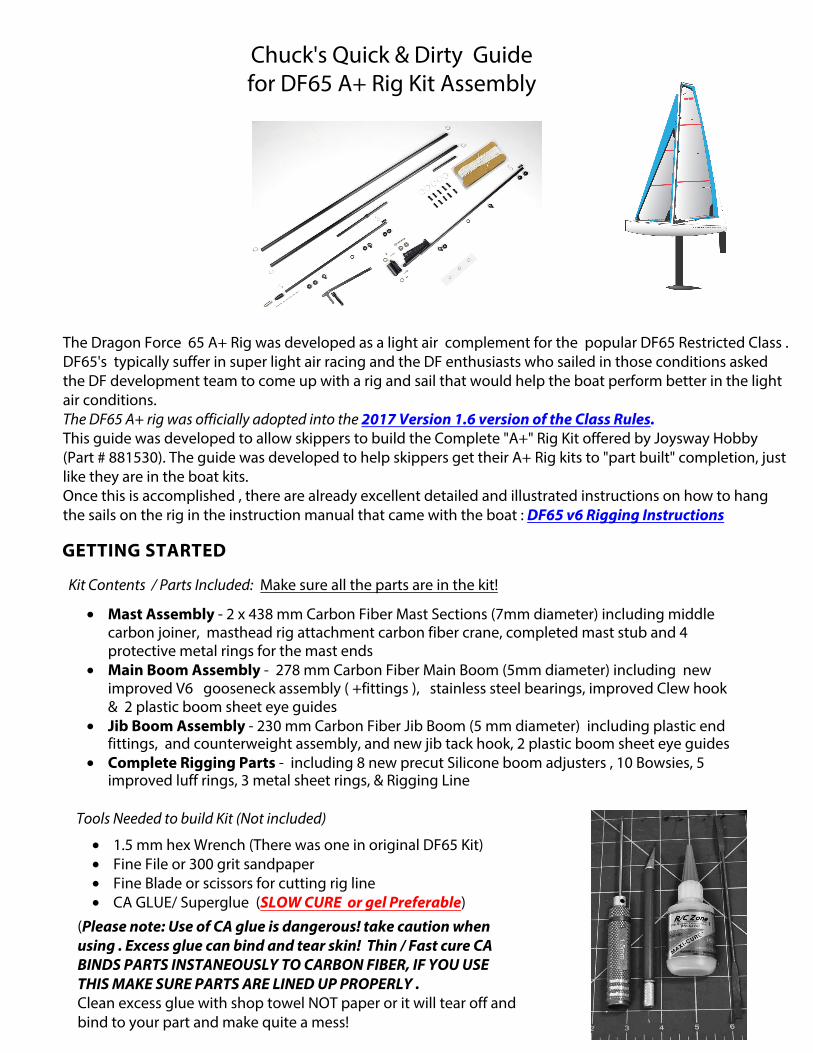
Chuck's Quick & Dirty Guide for DF65 A+ Rig Kit Assembly
The Dragon Force 65 A+ Rig was developed as a light air complement for the popular DF65 Restricted Class . DF65's typically suffer in super light air racing and the DF enthusiasts who sailed in those conditions asked the DF development team to come up with a rig and sail that would help the boat perform better in the light air conditions. The DF65 A+ rig was officially adopted into the 2017 Version 1.6 version of the Class Rules. This guide was developed to allow skippers to build the Complete "A+" Rig Kit offered by Joysway Hobby (Part # 881530). The guide was developed to help skippers get their A+ Rig kits to "part built" completion, just like they are in the boat kits.Once this is accomplished , there are already excellent detailed and illustrated instructions on how to hang the sails on the rig in the instruction manual that came with the boat : DF65 v6 Rigging Instructions
GETTING STARTED
Kit Contents / Parts Included: Make sure all the parts are in the kit!
• Mast Assembly - 2 x 438 mm Carbon Fiber Mast Sections (7mm diameter) including middle carbon joiner, masthead rig attachment carbon fiber crane, completed mast stub and 4 protective metal rings for the mast ends
• Main Boom Assembly - 278 mm Carbon Fiber Main Boom (5mm diameter) including new improved V6 gooseneck assembly ( +fittings ), stainless steel bearings, improved Clew hook & 2 plastic boom sheet eye guides
• Jib Boom Assembly - 230 mm Carbon Fiber Jib Boom (5 mm diameter) including plastic end fittings, and counterweight assembly, and new jib tack hook, 2 plastic boom sheet eye guides
• Complete Rigging Parts - including 8 new precut Silicone boom adjusters , 10 Bowsies, 5 improved luff rings, 3 metal sheet rings, & Rigging Line
Tools Needed to build Kit (Not included)
• 1.5 mm hex Wrench (There was one in original DF65 Kit)• Fine File or 300 grit sandpaper• Fine Blade or scissors for cutting rig line• CA GLUE/ Superglue (SLOW CURE or gel Preferable)
(Please note: Use of CA glue is dangerous! take caution when using . Excess glue can bind and tear skin! Thin / Fast cure CA BINDS PARTS INSTANEOUSLY TO CARBON FIBER, IF YOU USE THIS MAKE SURE PARTS ARE LINED UP PROPERLY .Clean excess glue with shop towel NOT paper or it will tear off and bind to your part and make quite a mess!
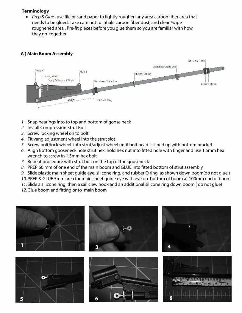
A ) Main Boom Assembly
Terminology• Prep & Glue , use file or sand paper to lightly roughen any area carbon fiber area that
needs to be glued. Take care not to inhale carbon fiber dust, and clean/wiperoughened area . Pre-fit pieces before you glue them so you are familiar with howthey go together
1. Snap bearings into to top and bottom of goose neck2. Install Compression Strut Bolt3. Screw locking wheel on to bolt4. Fit vang adjustment wheel into the strut slot5. Screw bolt/lock wheel into strut/adjust wheel until bolt head is lined up with bottom bracket6. Align Bottom gooseneck hole strut hex, hold hex nut into fitted hole with finger and use 1.5mm hex
wrench to screw in 1.5mm hex bolt7. Repeat procedure with strut bolt on the top of the gooseneck8. PREP 60 mm of one end of the main boom and GLUE into fitted bottom of strut assembly9. Slide plastic main sheet guide eye, silicone ring, and rubber O ring as shown down boom(do not glue )10. PREP & GLUE 5mm area for main sheet guide eye with eye on bottom of boom at 100mm end of boom11. Slide a silicone ring, then a sail clew hook and an additional silicone ring down boom ( do not glue)12. Glue boom end fitting onto main boom
1 3 4
5 6 8
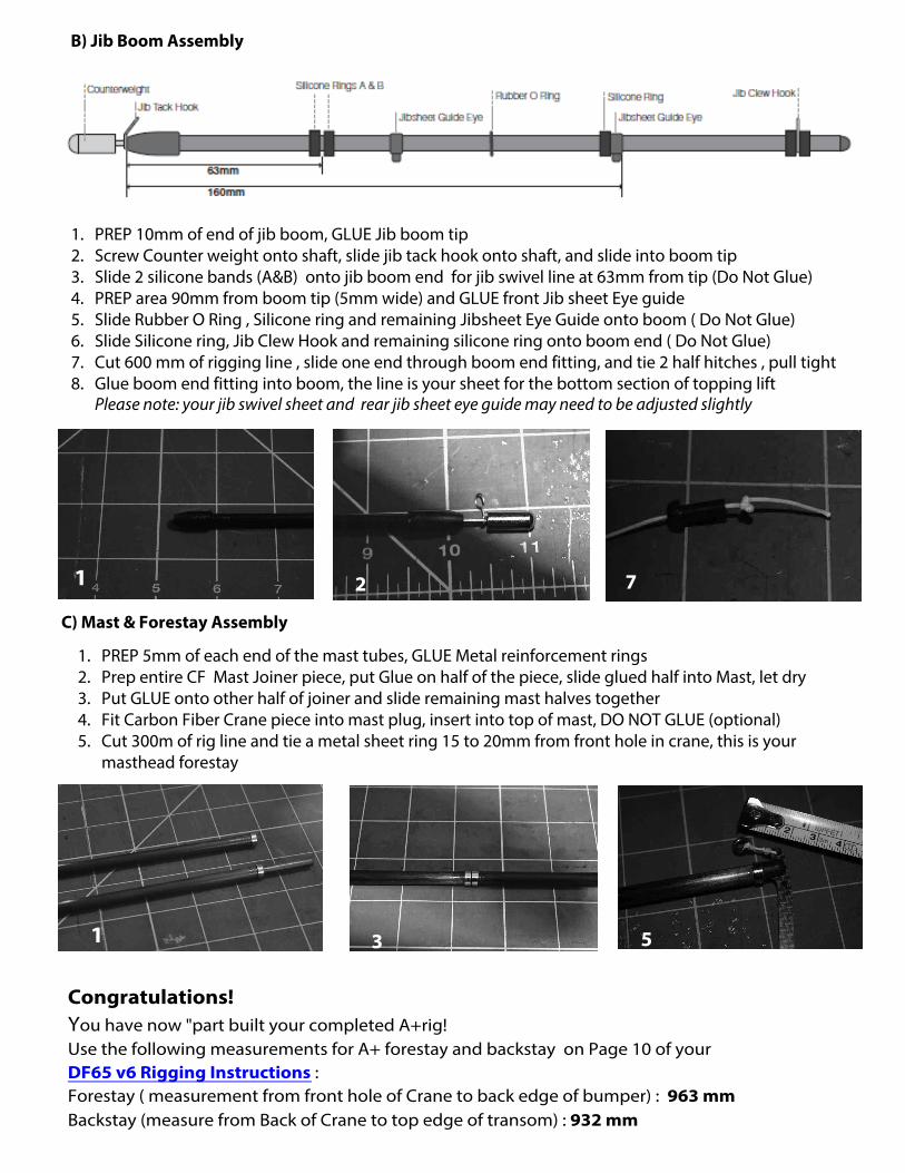
B) Jib Boom Assembly
1. PREP 10mm of end of jib boom, GLUE Jib boom tip2. Screw Counter weight onto shaft, slide jib tack hook onto shaft, and slide into boom tip3. Slide 2 silicone bands (A&B) onto jib boom end for jib swivel line at 63mm from tip (Do Not Glue)4. PREP area 90mm from boom tip (5mm wide) and GLUE front Jib sheet Eye guide5. Slide Rubber O Ring , Silicone ring and remaining Jibsheet Eye Guide onto boom ( Do Not Glue)6. Slide Silicone ring, Jib Clew Hook and remaining silicone ring onto boom end ( Do Not Glue)7. Cut 600 mm of rigging line , slide one end through boom end fitting, and tie 2 half hitches , pull tight8. Glue boom end fitting into boom, the line is your sheet for the bottom section of topping lift
Please note: your jib swivel sheet and rear jib sheet eye guide may need to be adjusted slightly
1 2 7
C) Mast & Forestay Assembly
1. PREP 5mm of each end of the mast tubes, GLUE Metal reinforcement rings2. Prep entire CF Mast Joiner piece, put Glue on half of the piece, slide glued half into Mast, let dry3. Put GLUE onto other half of joiner and slide remaining mast halves together4. Fit Carbon Fiber Crane piece into mast plug, insert into top of mast, DO NOT GLUE (optional)5. Cut 300m of rig line and tie a metal sheet ring 15 to 20mm from front hole in crane, this is your
masthead forestay
1 3 5
Congratulations! You have now "part built your completed A+rig! Use the following measurements for A+ forestay and backstay on Page 10 of your DF65 v6 Rigging Instructions : Forestay ( measurement from front hole of Crane to back edge of bumper) : 963 mm Backstay (measure from Back of Crane to top edge of transom) : 932 mm