Embed Size (px)
Citation preview
Chrysler CVT-2 Introduction
ATRA WEBINAR
Presented by:
Steve Garrett
ATRA
Sponsored By:

Today’s Presentation
Sponsored By:
A special thanks to the staff at Chrysler Training
group for help with this presentation.
Thanks
Internal combustion engines are most efficient
within a very narrow RPM window.
The range for power is typically at the upper RPM
levels
Best fuel economy is typically at the lower RPM
levels
The window for best economy and the lowest
emissions is typically less than 1000 RPM
Varied ratios available with a CVT meets the best
of all worlds, emissions, power, economy
CVT Compared to a Typical
Transmission
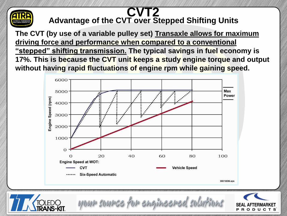
CVT2 Advantage of the CVT over Stepped Shifting Units
The CVT (by use of a variable pulley set) Transaxle allows for maximum
driving force and performance when compared to a conventional
“stepped” shifting transmission. The typical savings in fuel economy is
17%. This is because the CVT unit keeps a study engine torque and output
without having rapid fluctuations of engine rpm while gaining speed.
CVT2

CHRYSLER CVT 2 JATCO
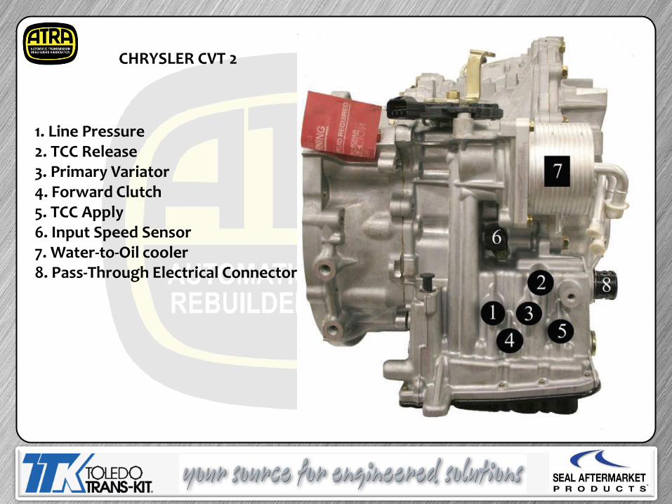
1. Line Pressure 2. TCC Release 3. Primary Variator 4. Forward Clutch 5. TCC Apply 6. Input Speed Sensor 7. Water-to-Oil cooler 8. Pass-Through Electrical Connector
CHRYSLER CVT 2
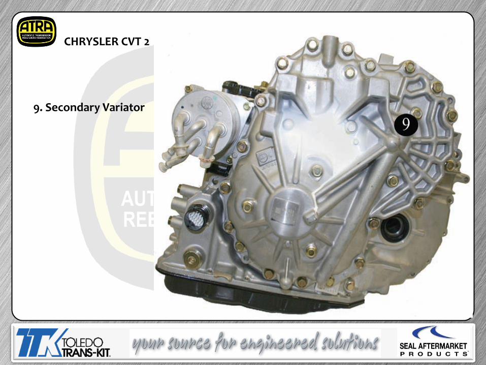
9. Secondary Variator
CHRYSLER CVT 2
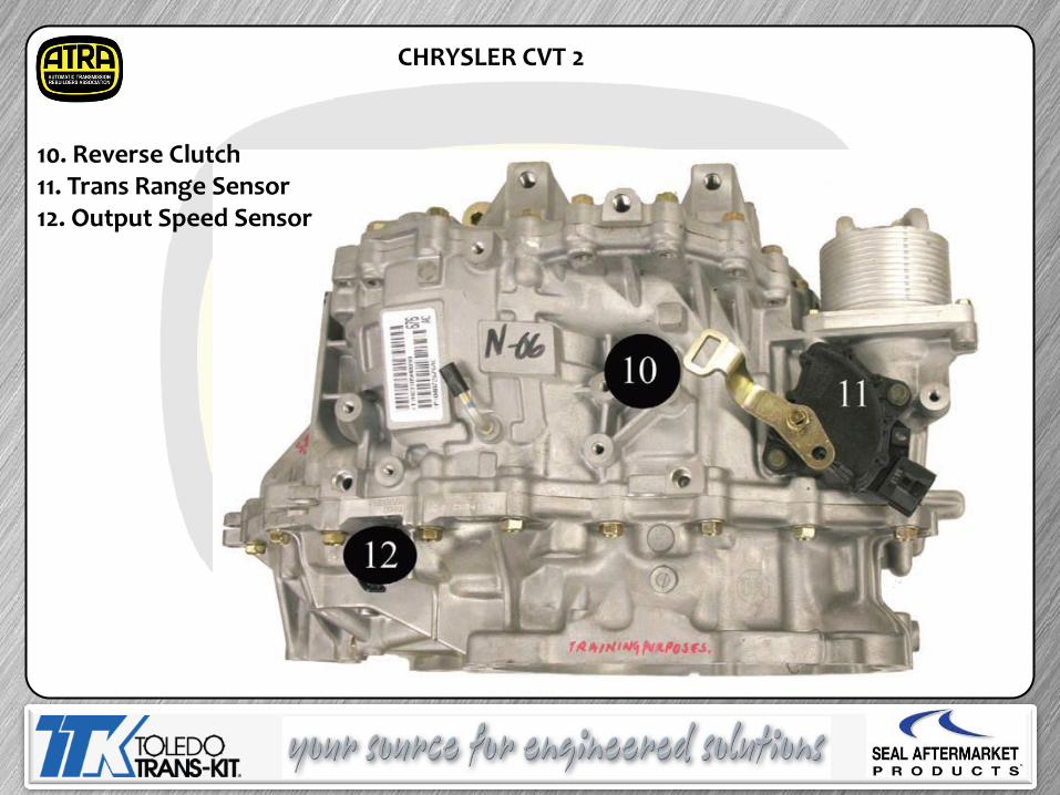
10. Reverse Clutch 11. Trans Range Sensor 12. Output Speed Sensor
CHRYSLER CVT 2
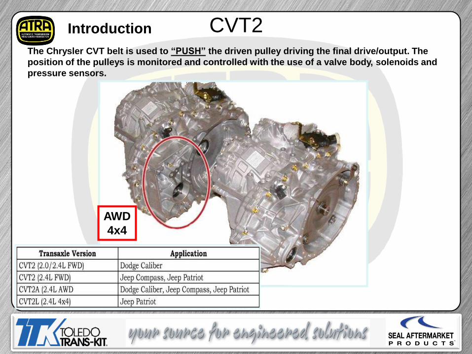
CVT2 Introduction
AWD
4x4
The Chrysler CVT belt is used to “PUSH” the driven pulley driving the final drive/output. The
position of the pulleys is monitored and controlled with the use of a valve body, solenoids and
pressure sensors.
CVT2
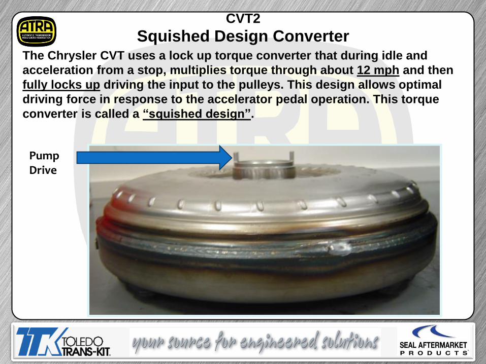
Squished Design Converter The Chrysler CVT uses a lock up torque converter that during idle and
acceleration from a stop, multiplies torque through about 12 mph and then
fully locks up driving the input to the pulleys. This design allows optimal
driving force in response to the accelerator pedal operation. This torque
converter is called a “squished design”.
Pump Drive
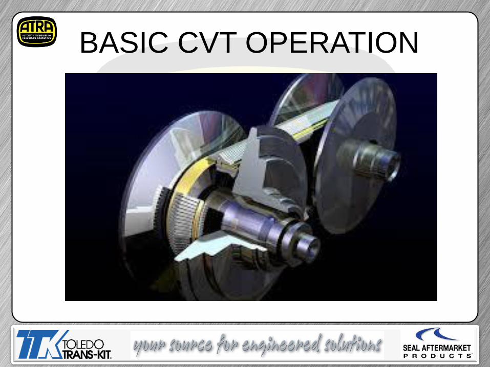
BASIC CVT OPERATION
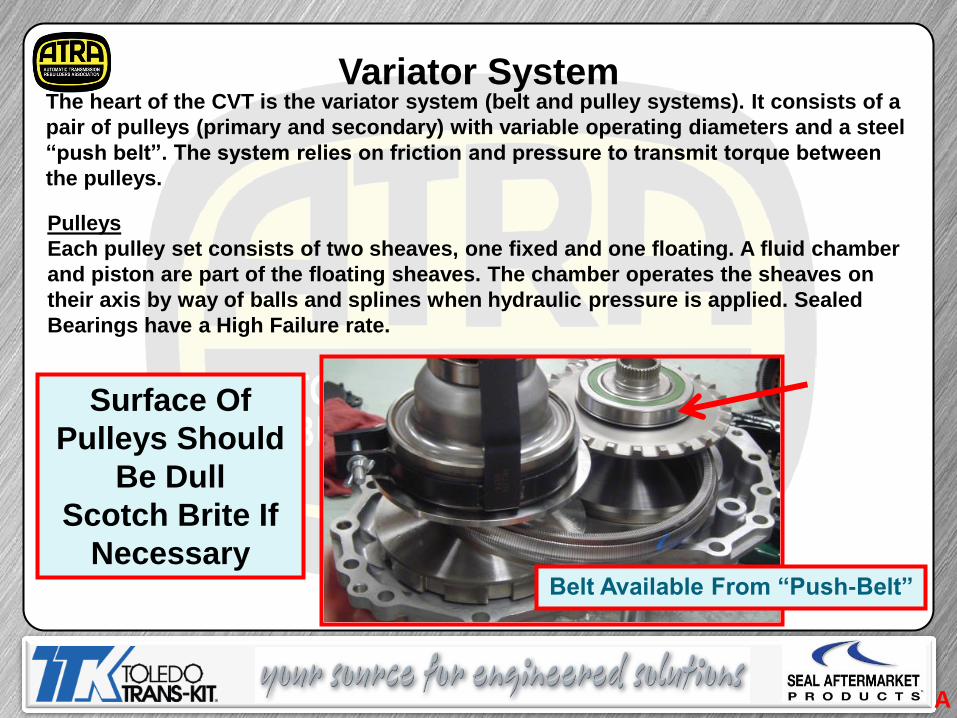
Variator System The heart of the CVT is the variator system (belt and pulley systems). It consists of a
pair of pulleys (primary and secondary) with variable operating diameters and a steel
“push belt”. The system relies on friction and pressure to transmit torque between
the pulleys.
Pulleys
Each pulley set consists of two sheaves, one fixed and one floating. A fluid chamber
and piston are part of the floating sheaves. The chamber operates the sheaves on
their axis by way of balls and splines when hydraulic pressure is applied. Sealed
Bearings have a High Failure rate.
Surface Of
Pulleys Should
Be Dull
Scotch Brite If
Necessary
A
Belt Available From “Push-Belt”
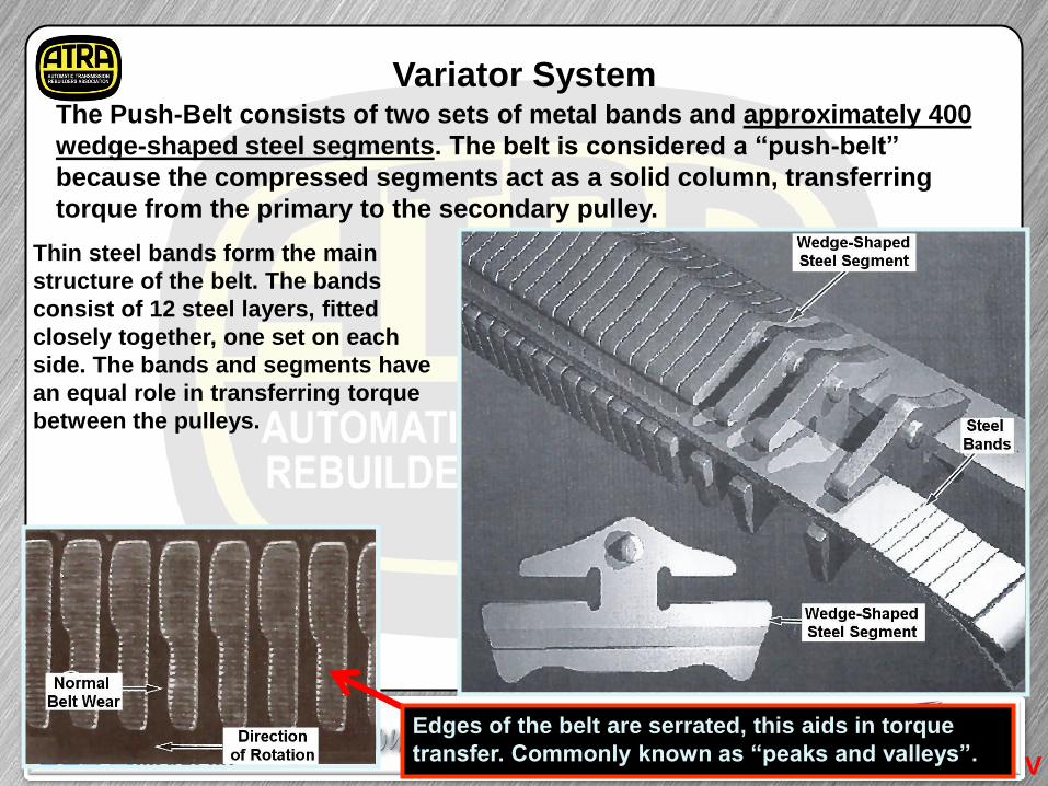
Variator System The Push-Belt consists of two sets of metal bands and approximately 400
wedge-shaped steel segments. The belt is considered a “push-belt”
because the compressed segments act as a solid column, transferring
torque from the primary to the secondary pulley.
Thin steel bands form the main
structure of the belt. The bands
consist of 12 steel layers, fitted
closely together, one set on each
side. The bands and segments have
an equal role in transferring torque
between the pulleys.
Edges of the belt are serrated, this aids in torque
transfer. Commonly known as “peaks and valleys”. V
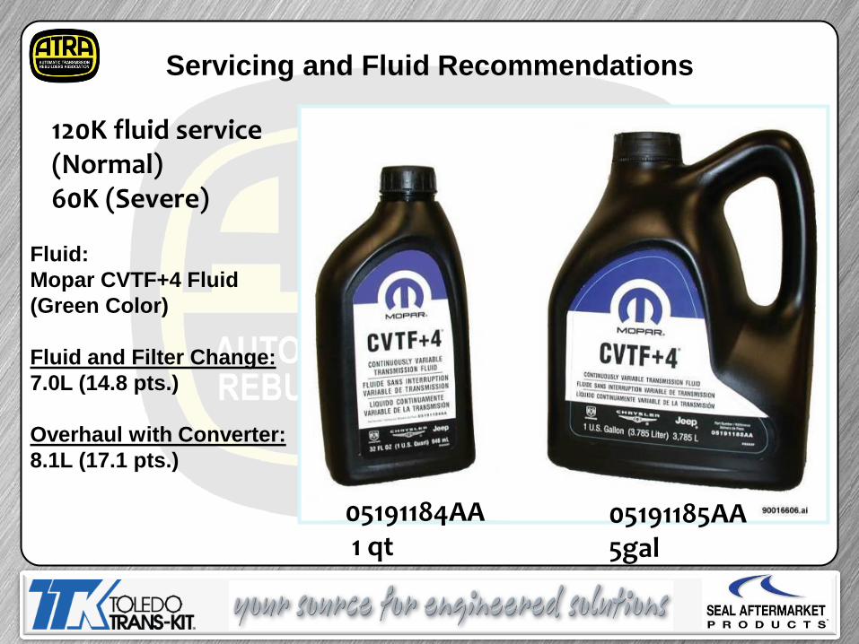
Servicing and Fluid Recommendations
Fluid:
Mopar CVTF+4 Fluid
(Green Color)
Fluid and Filter Change:
7.0L (14.8 pts.)
Overhaul with Converter:
8.1L (17.1 pts.)
05191184AA 1 qt
05191185AA 5gal
120K fluid service (Normal) 60K (Severe)
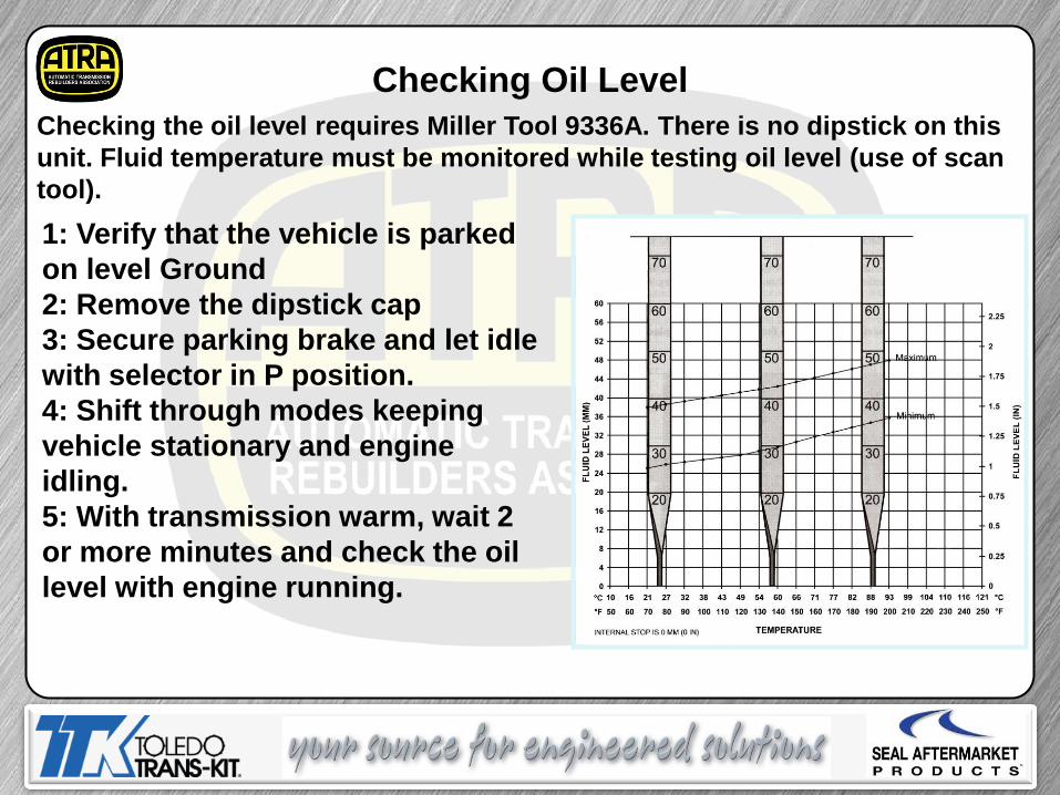
Checking Oil Level
Checking the oil level requires Miller Tool 9336A. There is no dipstick on this
unit. Fluid temperature must be monitored while testing oil level (use of scan
tool).
1: Verify that the vehicle is parked
on level Ground
2: Remove the dipstick cap
3: Secure parking brake and let idle
with selector in P position.
4: Shift through modes keeping
vehicle stationary and engine
idling.
5: With transmission warm, wait 2
or more minutes and check the oil
level with engine running.
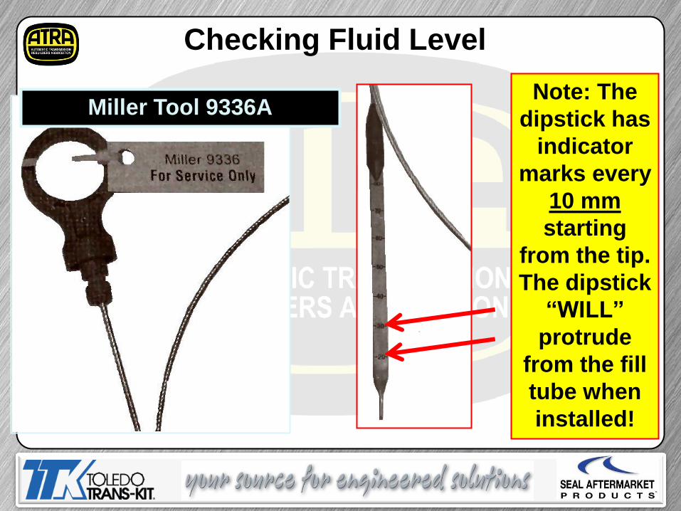
Checking Fluid Level
Miller Tool 9336A Note: The
dipstick has
indicator
marks every
10 mm
starting
from the tip.
The dipstick
“WILL”
protrude
from the fill
tube when
installed!
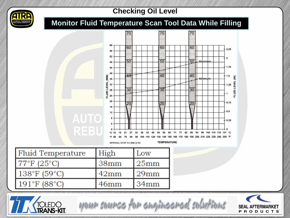
Checking Oil Level
Monitor Fluid Temperature Scan Tool Data While Filling
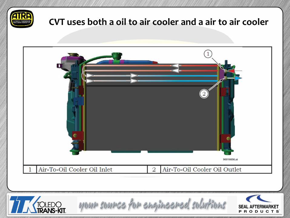
CVT uses both a oil to air cooler and a air to air cooler
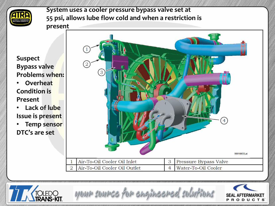
System uses a cooler pressure bypass valve set at 55 psi, allows lube flow cold and when a restriction is present
Suspect Bypass valve Problems when: • Overheat Condition is Present • Lack of lube Issue is present • Temp sensor DTC’s are set
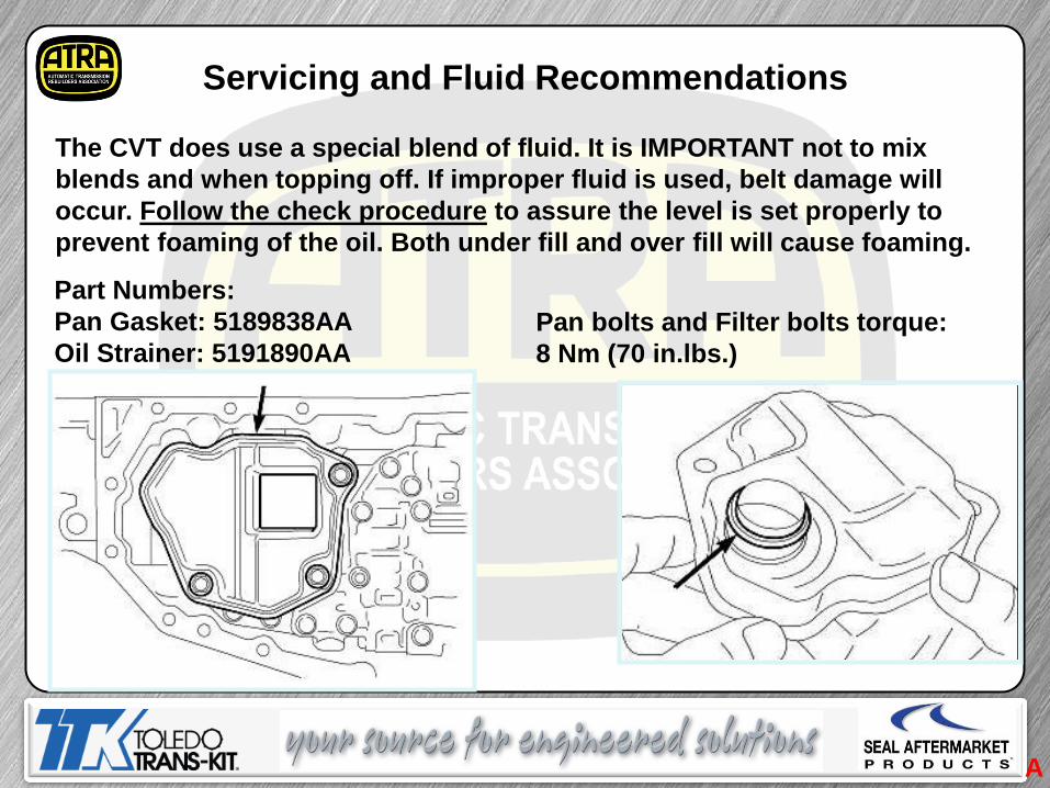
Servicing and Fluid Recommendations
The CVT does use a special blend of fluid. It is IMPORTANT not to mix
blends and when topping off. If improper fluid is used, belt damage will
occur. Follow the check procedure to assure the level is set properly to
prevent foaming of the oil. Both under fill and over fill will cause foaming.
Part Numbers:
Pan Gasket: 5189838AA
Oil Strainer: 5191890AA
Pan bolts and Filter bolts torque:
8 Nm (70 in.lbs.)
A
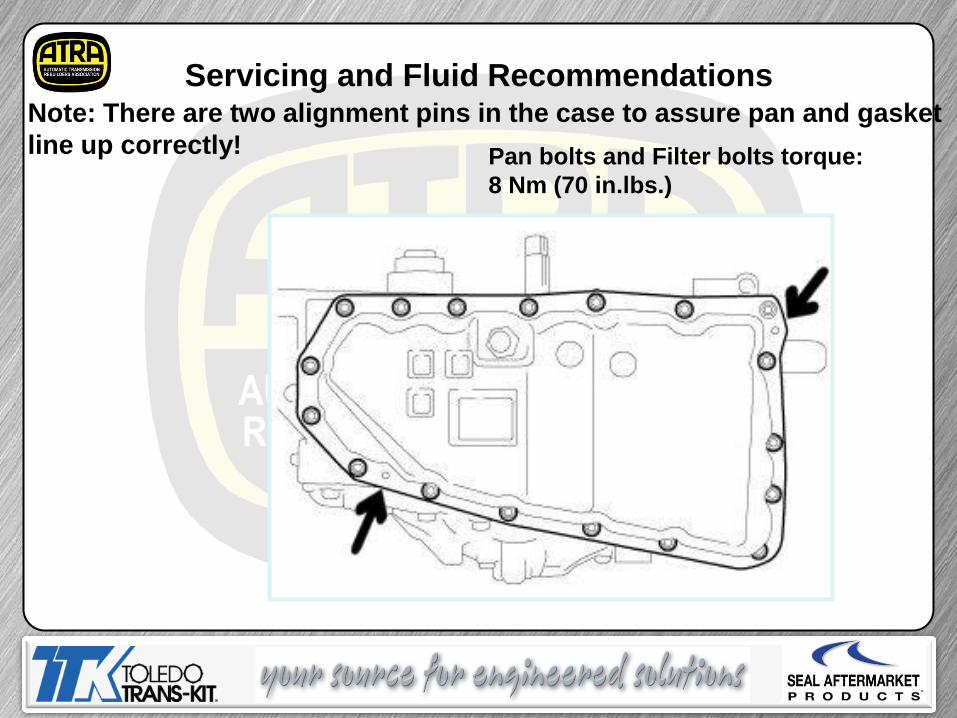
Servicing and Fluid Recommendations Note: There are two alignment pins in the case to assure pan and gasket
line up correctly! Pan bolts and Filter bolts torque:
8 Nm (70 in.lbs.)
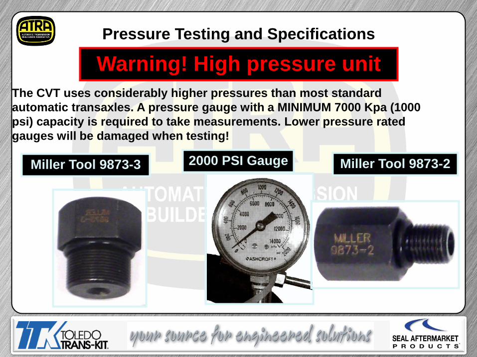
The CVT uses considerably higher pressures than most standard
automatic transaxles. A pressure gauge with a MINIMUM 7000 Kpa (1000
psi) capacity is required to take measurements. Lower pressure rated
gauges will be damaged when testing!
Pressure Testing and Specifications
Warning! High pressure unit
2000 PSI Gauge Miller Tool 9873-3 Miller Tool 9873-2
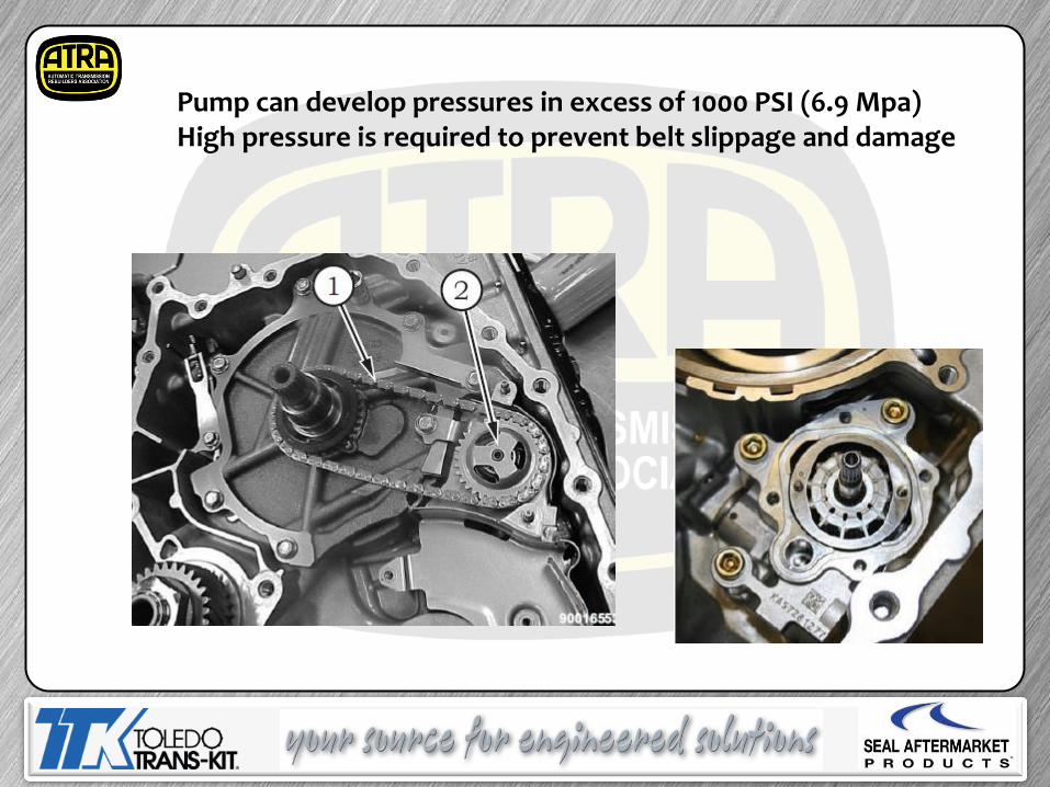
Pump can develop pressures in excess of 1000 PSI (6.9 Mpa) High pressure is required to prevent belt slippage and damage
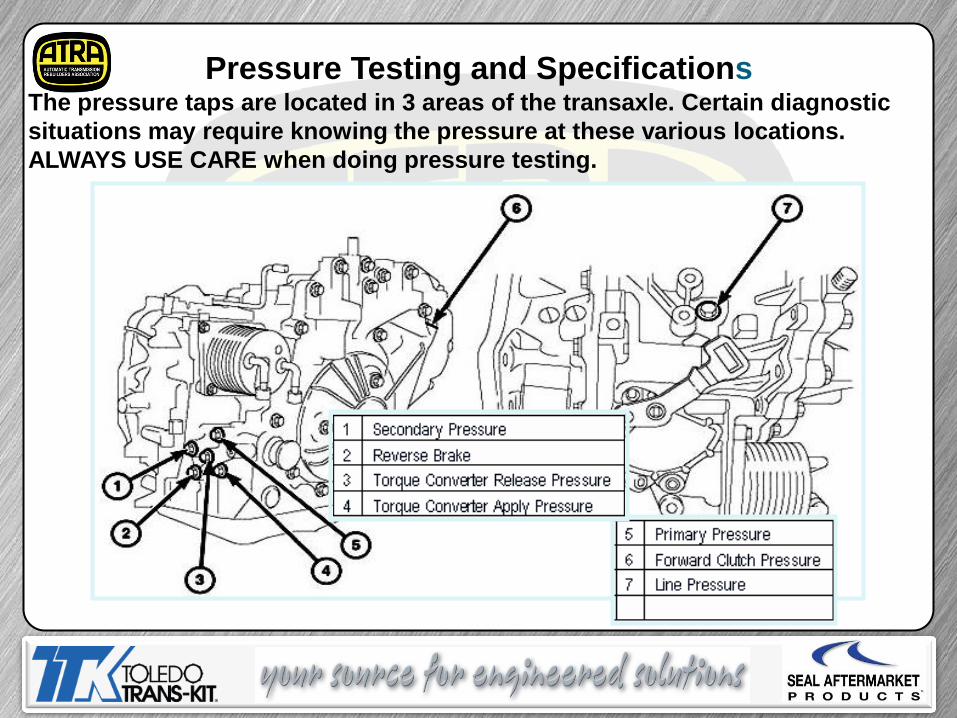
The pressure taps are located in 3 areas of the transaxle. Certain diagnostic
situations may require knowing the pressure at these various locations.
ALWAYS USE CARE when doing pressure testing.
Pressure Testing and Specifications
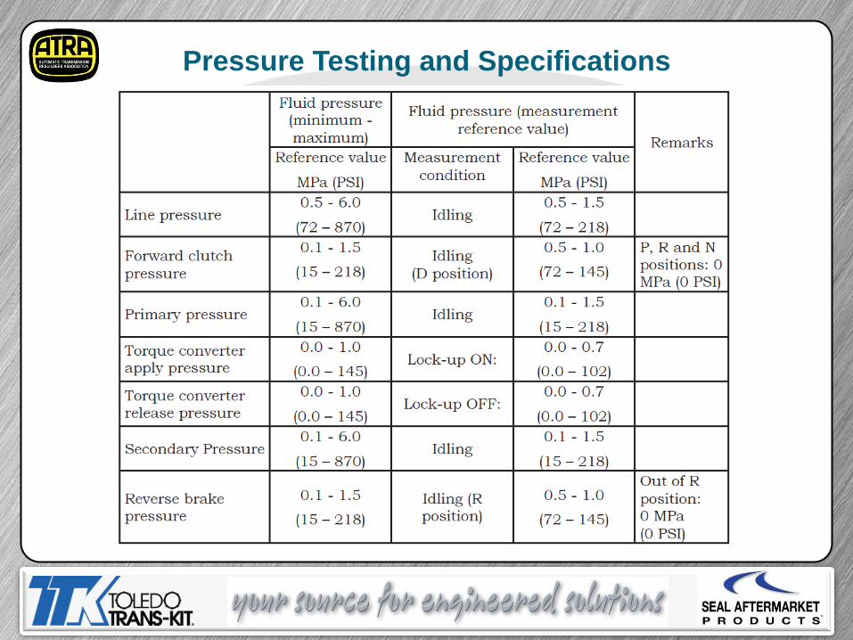
Pressure Testing and Specifications
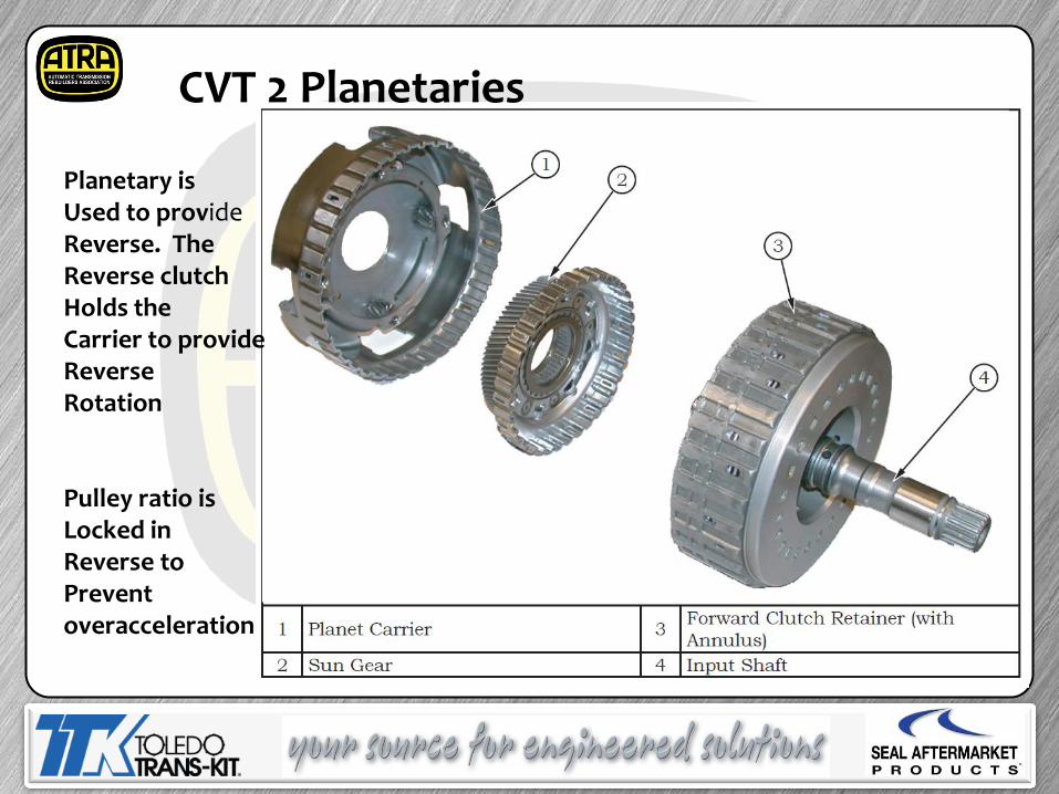
CVT 2 Planetaries
Planetary is Used to provide Reverse. The Reverse clutch Holds the Carrier to provide Reverse Rotation Pulley ratio is Locked in Reverse to Prevent overacceleration
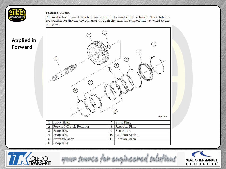
Applied in Forward
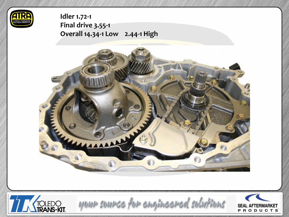
Idler 1.72-1 Final drive 3.55-1 Overall 14.34-1 Low 2.44-1 High
CHRYSLER CVT 2
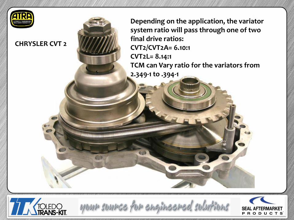
Depending on the application, the variator system ratio will pass through one of two final drive ratios: CVT2/CVT2A= 6.10:1 CVT2L= 8.14:1 TCM can Vary ratio for the variators from 2.349-1 to .394-1
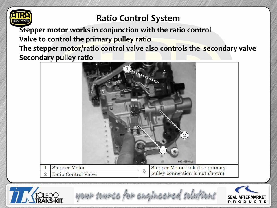
Ratio Control System Stepper motor works in conjunction with the ratio control Valve to control the primary pulley ratio The stepper motor/ratio control valve also controls the secondary valve Secondary pulley ratio
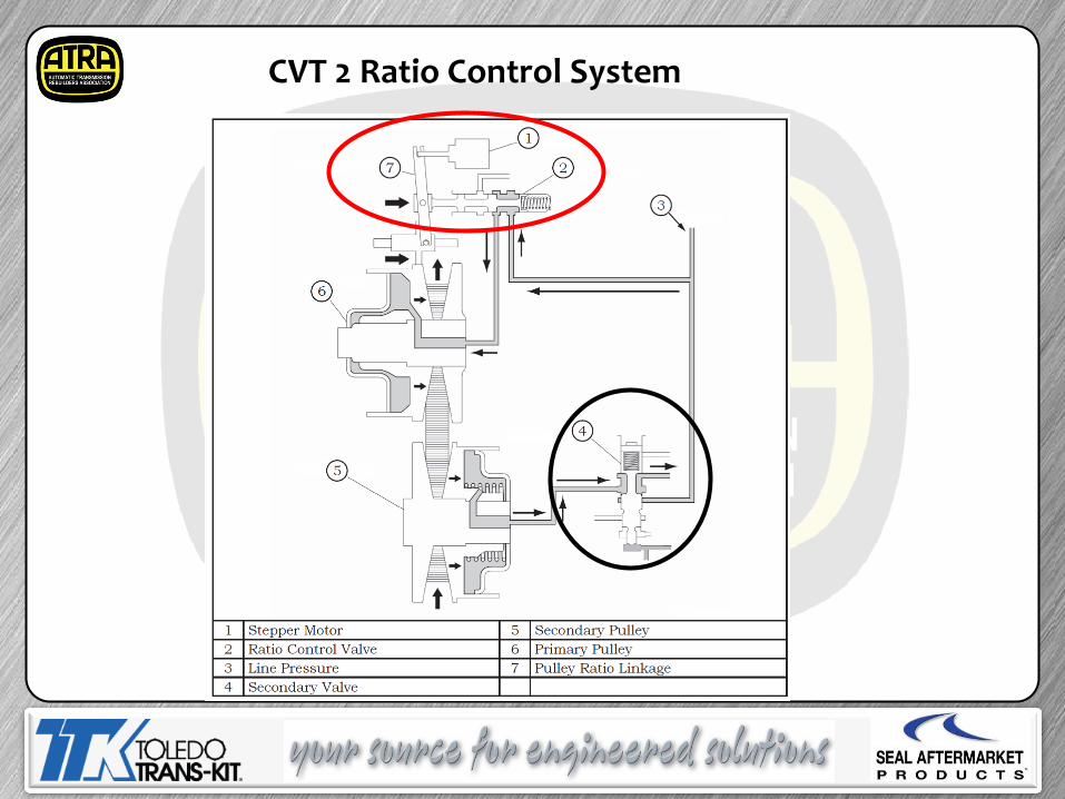
CVT 2 Ratio Control System
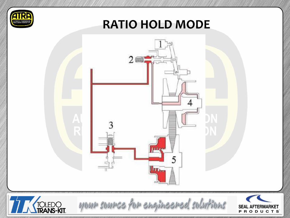
RATIO HOLD MODE
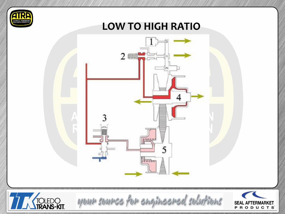
LOW TO HIGH RATIO
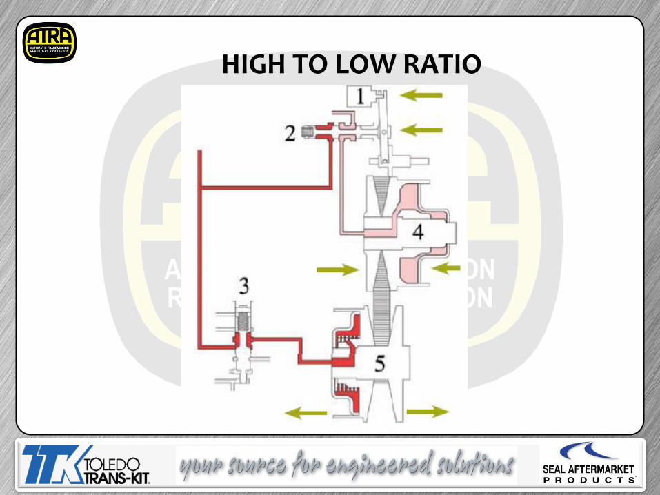
HIGH TO LOW RATIO
HydraulicOperation The oil pump is capable of producing system fluid pressures in excess of 6.9 MPa (1000 PSI). This high pressure is reduced by the valve body pressure regulator to supply the various systems. Operation of the CVT transaxle requires four levels of fluid pressure. *The primary and secondary pulleys require the highest pressure (up to 6.0 MPa (870 PSI)) to provide the necessary clamping force for the steel push-belt. *The second level of fluid pressure (up to 1.5 MPa (218 PSI)) is required for forward and reverse clutch operation. *The third level of fluid pressure (up to 1.0 MPa (145 PSI)) is required for TCC application. *Finally, the remaining fluid pressure (up to 0.4 MPa (60 PSI)) is used for transaxle lubrication and the fluid cooler circuits.
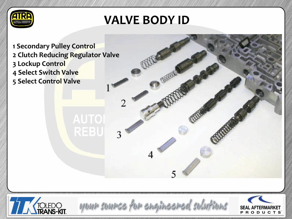
1 Secondary Pulley Control 2 Clutch Reducing Regulator Valve 3 Lockup Control 4 Select Switch Valve 5 Select Control Valve
VALVE BODY ID
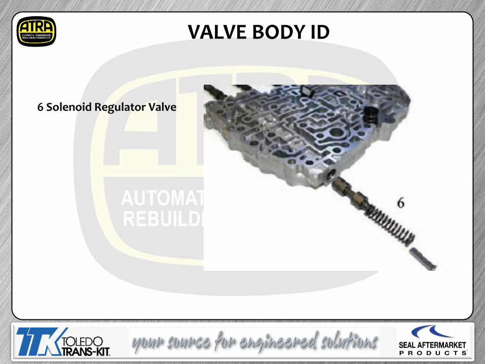
6 Solenoid Regulator Valve
VALVE BODY ID
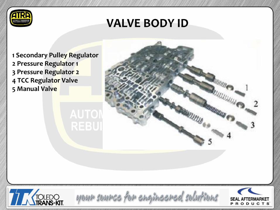
1 Secondary Pulley Regulator 2 Pressure Regulator 1 3 Pressure Regulator 2 4 TCC Regulator Valve 5 Manual Valve
VALVE BODY ID
Line Pressure Regulator Valve The line pressure regulator valve provides supply pressure to the ratio control valve, secondary valve, and down stream for clutch regulation. Circuit pressures for the primary and secondary pulleys range from 0.5 to 6 MPa (72 to 870 PSI). Ratio Control Valve • The ratio control valve is a spool valve that controls the variator ratio by ––controlling fluid flow into and out of the primary pulley. Secondary Valve• The secondary valve is a spool valve that controls the secondary pulley ––pressure and the variator system clamp force.
CVT 2 Valve function
Clutch Pressure Regulator Valve This valve provides the supply pressure necessary for the forward and reverse clutches, and down stream for TCC regulation. Circuit pressures for the forward and reverse clutches range from 0.1 to 1.5 MPa (15-218 PSI). Manual Valve• The manual valve is a spool valve that directs fluid to and away from the ––forward and reverse clutches based on shift lever position. Select Control Valve• Adjusts the forward and reverse clutch pressures–– TCC Regulator Valve The TCC regulator valve provides supply pressure necessary for the TCC and lube/cooler circuits. Circuit pressures range from 0.0 to 1.0 MPa (0.0 to 145 PSI). Lock-up Control Valve• Alternates torque converter clutch apply and release pressures.
CVT 2 Valve function
Secondary Pressure VFS The secondary pressure VFS controls secondary valve position by applying or removing hydraulic pressure, overcoming valve spring pressure. This action regulates clamp force on the variator system. LPVFS The LP VFS applies pressure to the end of the pressure regulator valve, overcoming spring pressure, to modulate line pressure available to the primary pulley and the secondary valve. Lock-up/Select Switch Solenoid The lock-up/select switch solenoid controls the select switch spool valve. TCC Solenoid VFS The TCC solenoid controls the lock up control spool valve and regulates forward and reverse clutch pressures. Select Switch Valve The select switch valve is a spool valve that is controlled by the lock-up/select switch solenoid. It diverts fluid between the lock-up and select control valves.
CVT 2 system component function
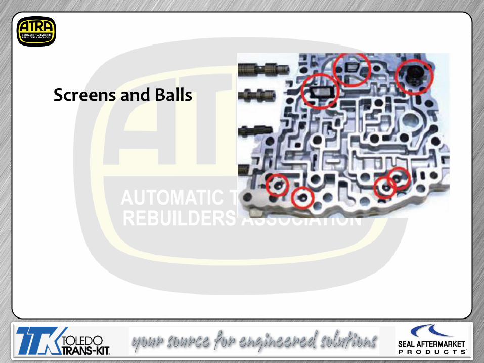
Screens and Balls
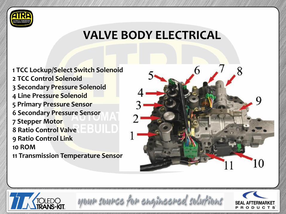
1 TCC Lockup/Select Switch Solenoid 2 TCC Control Solenoid 3 Secondary Pressure Solenoid 4 Line Pressure Solenoid 5 Primary Pressure Sensor 6 Secondary Pressure Sensor 7 Stepper Motor 8 Ratio Control Valve 9 Ratio Control Link 10 ROM 11 Transmission Temperature Sensor
VALVE BODY ELECTRICAL
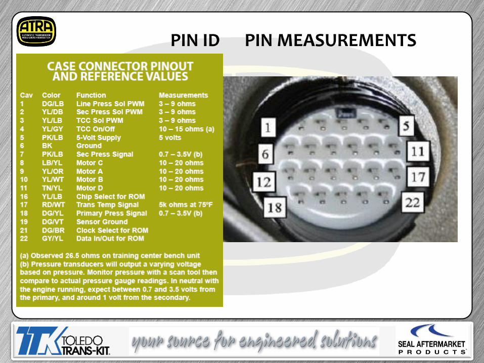
PIN ID PIN MEASUREMENTS
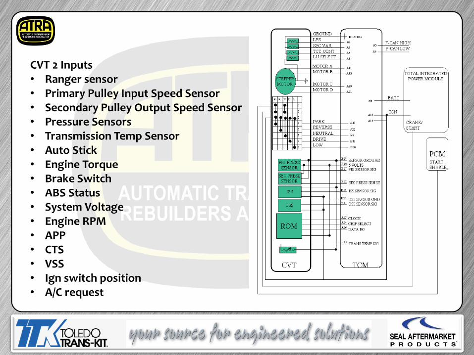
CVT 2 Inputs • Ranger sensor • Primary Pulley Input Speed Sensor • Secondary Pulley Output Speed Sensor • Pressure Sensors • Transmission Temp Sensor • Auto Stick • Engine Torque • Brake Switch • ABS Status • System Voltage • Engine RPM • APP • CTS • VSS • Ign switch position • A/C request
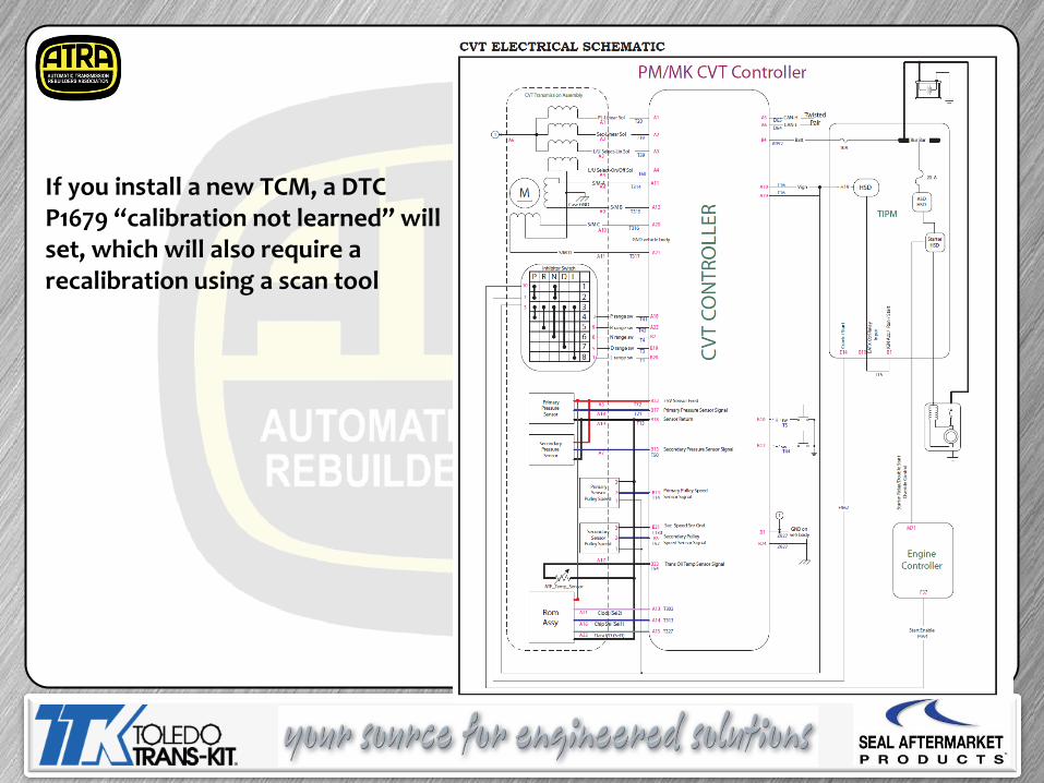
If you install a new TCM, a DTC P1679 “calibration not learned” will set, which will also require a recalibration using a scan tool
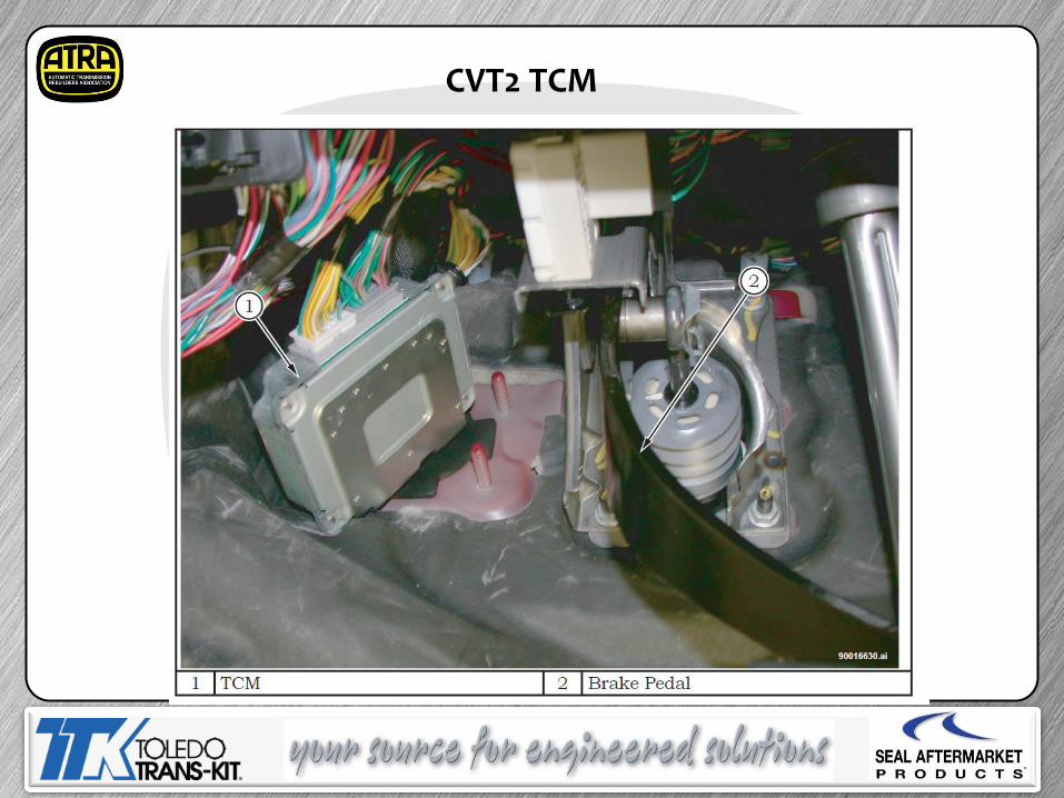
CVT2 TCM
TCM Replacement
CVT TCM Replacement The CVT has a coded ROM chip in-harness at production. This chip has values that are unique to each transaxle (2.0LPM/2.4LPM& MK/2.4L4x4 Jeep Variant). Essentially, this chip tells the TCM what type of CVT it is controlling. When the ignition key is turned on the first time at production, the TCM learns the values stored in the chip as well as vehicle configuration information (engine, tire size, if ABS, etc.) from the BUS. TCM replacement requires a flash in service. One controller part number will be provided for service. This supplied controller is generic, and has minimal functionality to provide the MIL, power, and ground to facilitate the flash. The vehicle Is not drivable until the flash is performed. The TCM has the ability to detect a CVT or TCM replacement. If a controller is replaced with one from another working vehicle, or a new CVT is installed, a “mismatch” P-Code is set, the MIL is illuminated, and the transaxle is placed in default/safe mode to protect the CVT hardware. The SCAN tool must be used to clear TCM memory of previously learned calibration values
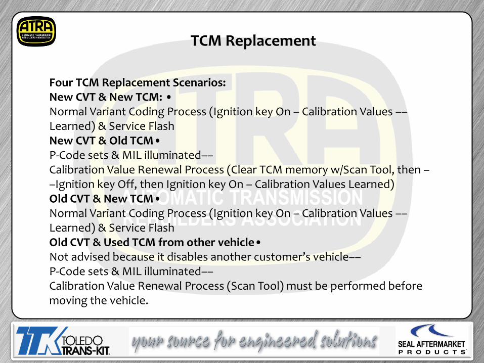
Four TCM Replacement Scenarios: New CVT & New TCM: • Normal Variant Coding Process (Ignition key On – Calibration Values ––Learned) & Service Flash New CVT & Old TCM• P-Code sets & MIL illuminated–– Calibration Value Renewal Process (Clear TCM memory w/Scan Tool, then ––Ignition key Off, then Ignition key On – Calibration Values Learned) Old CVT & New TCM• Normal Variant Coding Process (Ignition key On – Calibration Values ––Learned) & Service Flash Old CVT & Used TCM from other vehicle• Not advised because it disables another customer’s vehicle–– P-Code sets & MIL illuminated–– Calibration Value Renewal Process (Scan Tool) must be performed before moving the vehicle.
TCM Replacement
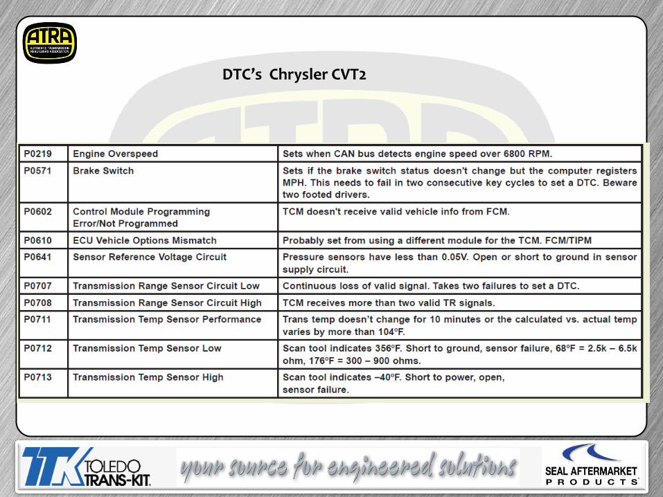
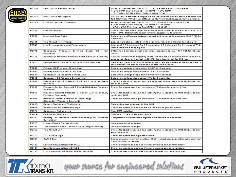
DTC’s Chrysler CVT2
Today’s Presentation
Sponsored By:
THANK YOU
Questions
Survey
Thanks For Attending, See you during our
Next ATRA webinar
Thanks to our supplier for the support