Embed Size (px)
Citation preview
Chemical Engineering Journal 92 (2003) 193–199
Chromic acid recovery from waste acid solution by an ion exchangeprocess: equilibrium and column ion exchange modeling
S.H. Lin∗, C.D. KiangDepartment of Chemical Engineering, Yuan Ze University, Chungli 320, Taiwan
Abstract
A four-step ion exchange process for chromic acid recovery from waste acid solution was proposed in the present work. Strong acidanionic (OH-type) ion exchange resin was used in the first step to capture chromic acid (H2CrO4) which was converted to sodium chromate(Na2CrO4) by sodium hydroxide (NaOH) solution in the second step. Sodium chromate was converted back to chromic acid using strongbase cationic (H-type) ion exchange resin in the third step and in the fourth step, the exhausted ion exchange resin was regenerated byhydrochloric acid (HCl) solutions. Batch and column experimental tests were conducted to provide data for theoretical modeling and toverify the system performance of the recovery process. Results of batch equilibrium tests indicated that Freundlich isotherm describeswell both chromic acid and sodium chromate adsorption equilibrium. A theoretical column model adopted in this work was found todescribe well the ion exchange breakthrough characteristics. The four-step process was proved to be efficient and was capable of providingcontinuous chromic acid recovery operation.© 2002 Elsevier Science B.V. All rights reserved.
Keywords: Chromic acid recovery; Four-step ion exchange process; Anionic and cationic resins; Column adsorption; Equilibrium; Isotherms
1. Introduction
Chromic acid (H2CrO4) is widely employed in many in-dustries for plating, leather tanning, electrolytic strippingof copper, anodizing of aluminum, passivation of cadmium,magnesium and zinc[1,2]. In more recent development inthe printed circuit board manufacturing, strong chromic acidis used as an oxidant in the desmearing operation. In theseindustries, a large quantity of waste chromic acid solution iscommonly generated. The public concerns about this wasteacid solution stem from the fact that the chromium in theaqueous solution can be readily adsorbed by marine animalsand directly enter the human food chains, thus, presentinga high health risk to consumers[2–4]. Hence, the wastechromic acid solution has been strictly regulated by the gov-ernment. It must be properly treated before it is allowed fordirect discharge to natural water streams.
During the past several decades, many physicochemicalmethods have been developed for chromium removal fromwaste chromium acid solution. These methods include chem-ical coagulation, adsorption, extraction, ion exchange andmembrane separation process[3,5–12]. In many industrialpractices in Taiwan, a popular method is to reduce the hex-
∗ Corresponding author. Fax:+886-3-455-9373E-mail address: [email protected] (S.H. Lin).
avalent chromium (Cr6+) by sodium sulfite (Na2SO3) totrivalent form (Cr3+). The trivalent chromium is in turn con-verted under alkaline condition to Cr(OH)3 which precipi-tates out of the aqueous solution. Such a process is not easyto operate and generates a significant amount of toxic sludgethat entails careful further disposal. Alternatively, ion ex-change arn adsorption are becoming a popular method thathas received much attention in recent years. Dikshit[13],Santiago et al.[14], Khan et al.[15], Sharma and Forster[16], Zhao et al.[17] and Hamadi et al.[18] were inves-tigators studying chromium removal by ion exchange andvarious adsorbents. The previous investigations focused pri-marily on reducing the chromium content in the waste acidsolution to the discharge standard. In fact, the chromic acidin the waste solution, if properly dealt with, can be recov-ered as a raw material and recycled back to the electroplat-ing and other industrial processes for reuse. Relatively littleattention has been paid to this aspect in the past.
The objective of the present study is to address this issueby employing a four-step ion exchange process in recover-ing chromic acid from the waste solution. In this multi-stepprocess, two types of ion exchange resins were used. In thefirst two steps, chromate was captured and concentrated us-ing a strong base anionic ion exchange resin while in thelast two steps, the chromate was converted to chromic acidby a strong acid cationic ion exchange resin. The present
1385-8947/02/$ – see front matter © 2002 Elsevier Science B.V. All rights reserved.PII: S1385-8947(02)00140-7
194 S.H. Lin, C.D. Kiang / Chemical Engineering Journal 92 (2003) 193–199
multi-step process allows continuous operation of chromicacid recovery in a efficient manner and thus has potentialpractical applications.
2. Ion exchange process for chromic acid recovery
In this section, the basic principle of the two-stage ion ex-change process will be illustrated. The process is in essencea four-step operation. In the first step, chromate is adsorbedonto the solid (the OH-type resin) phase by exchange withOH− which is combined with H+ in the aqueous solution toform H2O. In the second step, the adsorbed chromate in thesolid phase is replaced under alkaline condition by OH− andis detached. It combines with Na+ in the aqueous solutionfor form Na2CrO4. These first two steps of ion exchangecan be represented by
adsorption : 2R–OH+ H2CrO4 → R2–CrO4 + 2H2O
desorption : R2–CrO4 + 2NaOH→ 2R–OH+ Na2CrO4
where R–OH represents the OH-type ion exchange resin.It is noted that between the adsorption and desorptionsteps, chromic acid in the original waste acid solution issignificantly concentrated although it form a sodium salt(Na2CrO4) after desorption, as shown in the second reaction.
The sodium chromate obtained from the second ion ex-change (desorption) step needs to be converted back tochromic acid. This is accomplished in the third step usingthe H-type ion exchange resin. In this step, the sodium ion inthe aqueous solution is adsorbed by ion exchange with H+on the solid phase and the chromic acid is formed accordingto
conversion : Na2CrO4 + 2R–H→ H2CrO4 + 2R–Na
where R–H is the H-type ion exchange resin. In the finalstep, the exhausted ion exchange resin (R–Na) is regener-ated by hydrochloric acid (HCl) solution with which H+ isexchanged with Na+ on the solid phase. This last step isrepresented by
regeneration : R–Na+ HCl → R–H+ NaCl
These four steps complete the present chromic acid recov-ery process. In summary, the multi-step ion exchange worksthis way: the chromic acid is captured from the waste acidsolution in the first step using the OH-type ion exchangeresin and converted to sodium chromate in the second us-ing NaOH solution. The second step also serves to regener-ate the exhausted OH-type ion exchange resin. The sodiumchromate is then converted back chromic acid in the thirdstep utilizing the H-type ion exchange resin and is recovered.Finally, the exhausted H-type ion exchange resin is regen-erated in the fourth step using HCl solution. The stepwiseprocess permits continuous and efficient operation for prac-tical purposes. In the followingSection 3, the equilibrium
adsorption capacities of the ion exchange resins and the per-formances of the multi-step ion exchange process will betested and evaluated.
3. Experimental studies
The ion exchange resins employed in this study were theAmbersep 900 and 132 resins, as obtained from Rohm andHaas Co. (Philadelphia, PA). The Ambersep 900 is a strongacid anionic resin (OH-type) and the Ambersep 132 is astrong base cationic resin (H-type). For pretreatment, bothAmbersep resins were washed several times first by deion-ized water, followed by rinsing with acetone to remove allimpurities on the resins. They were then rinsed with deion-ized water several times and dried at 60◦C in an oven forat least 24 h. For experimental batch and column tests, thestock solutions of chromic acid (H2CrO4) and sodium chro-mate (Na2CrO4) were prepared by dissolving in deionizedwater appropriate amounts of reagent grade chromium ox-ide (CrO3) and sodium chromate, as obtained from E MerckGmbH (Darmstadt, Germany).
For equilibrium adsorption experimental tests, 250 mlof the stock chromic acid solution were put in a flaskand 0.1 g of pretreated Ambersep 900 resin was added.The flask was sealed and placed in a constant-temperatureshaker maintained at 25◦C and 120 cycles per minuteshaking speed for 24 h to ensure adsorption equilibrium.Aqueous samples were then taken for hexavalent chromium(Cr6+) measurements using a GBC 932 atomic absorptionspectrophotometer (GBC Scientific Equipment Pvt. Ltd.,Melbourne, Australia). The equilibrium experimental testswere repeated for solutions of different initial chromic acidconcentrations to ensure that sufficient data were collectedfor isotherm identification of Cr6+ adsorption by Ambersep900 resin. Similar experimental tests were performed forNa2CrO4 equilibrium adsorption by Ambersep 132 that ad-sorbed the sodium ion (Na+) from the aqueous solution. Theequilibrium sodium ion concentration in the aqueous solu-tion was measured using a JASCO high performance liquidchromatography (HPLC; Model PU 980i, JASCO, Inc.,Tokyo, Japan). Again, sufficient number of equilibrium testruns were conducted for different initial sodium chromateconcentrations to gather data for isotherm identification ofsodium adsorption by the Ambersep 132 resin. It is notedthat the equilibrium and the following column test runs werereplicated at least once to ensure the accuracy of the col-lected data and the average of two data sets was reported. Innearly all instances, the accuracy of data was very good, withthe data being deviated from the average in less than 2%.
The above equilibrium adsorption tests permitted de-termination of the equilibrium amounts of chromate andsodium ions adsorbed by the Ambersep 900 and 132 ionexchange resins, respectively, for various initial chromicacid and sodium chromate concentrations. However, theperformance of the multi-step adsorption/regeneration
S.H. Lin, C.D. Kiang / Chemical Engineering Journal 92 (2003) 193–199 195
process outlined in the previous section needs to be evalu-ated in column tests.
For the column ion exchange test runs, a pyrex tubeof 2 cm i.d. and 30 cm height was used. The column wasequipped with an external water jacket for temperature con-trol. Ten grams of pretreated Ambersep 900 was randomlypacked in the column to a bed volume (BV) of 22 cm3.The stock chromic acid solution with a Cr6+ concentrationbetween 250 and 750 mg/l was fed to the top of the resincolumn by a feed pump at a desired rate between 10 and30 ml/min. Samples were taken periodically at the bottomof the resin column for Cr6+ concentration measurement us-ing the GBC 932 atomic absorption spectrophotometer. Asa test run was started, the exit Cr6+ concentration was ini-tially nil and after a certain time had elapsed, it began torise. The run continued until the exit Cr6+ concentration be-came close to the inlet. For the Cr6+ desorption (the secondstep), 10 wt.% NaOH solution was fed to the top of columnat one half of the adsorption feeding rate. The same GBC932 AA was used to determine the Cr6+ concentration inthe exit samples. A desorption run was terminated when theexit Cr6+ concentration was close to nil.
For conversion of sodium chromate to chromic acid, thestock sodium chromate solution was fed to the top of thecolumn randomly packed with 12 g of Ambersep 132 ionexchange resin. The feed flow rate was chosen between 5and 15 ml/min. The sodium ion (Na+) concentration in theaqueous solution exiting the column was detected using theJASCO PU 980i HPLC. A test run was terminated when theexit Na+ concentration was close to the inlet. Finally, the ex-hausted Ambersep 132 column was regenerated by feeding5 wt.% HCl solution at a flow rate between 5 and 15 ml/min.The sodium ion concentration in the exit stream was moni-tored periodically by the JASCO HPLC. A regeneration runwas completed when no more sodium ion was detected inthe exit solution.
4. Results and discussion
4.1. Equilibrium ion exchange isotherms
Two general isotherms commonly employed to describethe equilibrium ion exchange relation between the liquid andsolid phases are the Langmuir and the Freundlich models[9] which are represented by
Qe = abCe
1 + bCe(1)
Qe = KC1/ne (2)
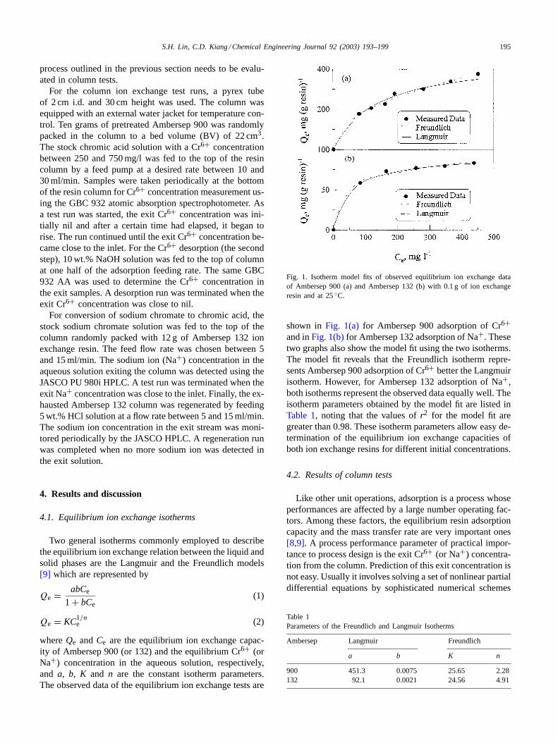
whereQe andCe are the equilibrium ion exchange capac-ity of Ambersep 900 (or 132) and the equilibrium Cr6+ (orNa+) concentration in the aqueous solution, respectively,and a, b, K and n are the constant isotherm parameters.The observed data of the equilibrium ion exchange tests are
Fig. 1. Isotherm model fits of observed equilibrium ion exchange dataof Ambersep 900 (a) and Ambersep 132 (b) with 0.1 g of ion exchangeresin and at 25◦C.
shown inFig. 1(a) for Ambersep 900 adsorption of Cr6+and inFig. 1(b)for Ambersep 132 adsorption of Na+. Thesetwo graphs also show the model fit using the two isotherms.The model fit reveals that the Freundlich isotherm repre-sents Ambersep 900 adsorption of Cr6+ better the Langmuirisotherm. However, for Ambersep 132 adsorption of Na+,both isotherms represent the observed data equally well. Theisotherm parameters obtained by the model fit are listed inTable 1, noting that the values ofr2 for the model fit aregreater than 0.98. These isotherm parameters allow easy de-termination of the equilibrium ion exchange capacities ofboth ion exchange resins for different initial concentrations.
4.2. Results of column tests
Like other unit operations, adsorption is a process whoseperformances are affected by a large number operating fac-tors. Among these factors, the equilibrium resin adsorptioncapacity and the mass transfer rate are very important ones[8,9]. A process performance parameter of practical impor-tance to process design is the exit Cr6+ (or Na+) concentra-tion from the column. Prediction of this exit concentration isnot easy. Usually it involves solving a set of nonlinear partialdifferential equations by sophisticated numerical schemes
Table 1Parameters of the Freundlich and Langmuir Isotherms
Ambersep Langmuir Freundlich
a b K n
900 451.3 0.0075 25.65 2.28132 92.1 0.0021 24.56 4.91
196 S.H. Lin, C.D. Kiang / Chemical Engineering Journal 92 (2003) 193–199
with proper identification of a number of system parameters[9]. As an alternative, a macroscopic version was developedfrom the original microscopic model by Bohart and Adams[19] and Thomas[20] for describing the solute breakthroughbehavior of a column adsorber. The main advantages of thismodel are its simplicity and reasonable accuracy in predict-ing the breakthrough curves (times) under various operatingconditions. The macroscopic model is represented by
ln
(C0 − C
C
)= ln
[exp
(k1QeM
F
)− 1
]− k1C0t (3)
where C is the solute concentration in the exit aqueousstream at timet (mg/l), C0 the inlet solute concentration(mg/l), k1 the rate constant of adsorption (l/(mg h)),Qethe equilibrium solid-phase concentration of sorbed solute(gram of solute per gram of adsorbent),M the mass of ad-sorbent (g),F the flow rate (l/h) andt the time (h). Due torelatively larger value of exp[(k1QeM)/F] than 1 in most in-stances,Eq. (3)can be rewritten as:
ln
(C
C0 − C
)=k1C0t−k1QeM
F=k1C0
(t − QeM
C0F
)(4)
The equation was also adopted by Hutchins[21] for thedesign of activated carbon adsorption system. According toEq. (4), the left-hand quantity, ln[C/(C0 − C)], is a linearfunction of time (t) for a given set of system and operatingconditions. Hence, a linear plot of ln[C/(C0 − C)] versust yields a slope and intercept for estimation of the modelparameters. In fact, the above equation is essentially thesame as the simplified logistic function that describes thebiological or population growth and distribution[22]:
ln
(C
C0 − C
)= k(t − τ) (5)
Comparison ofEqs. (4) and (5)reveals thatk = k1C0 andτ = QeM/(C0F). It is noted thatQeM/(C0F) in Eq. (4)or τ
in Eq. (5)represents the time whenC = C0/2.The two parameters inEq. (5)can be readily determined
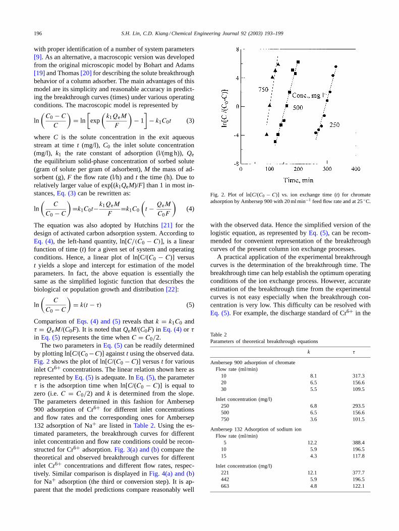
by plotting ln[C/(C0−C)] againstt using the observed data.Fig. 2 shows the plot of ln[C/(C0 − C)] versust for variousinlet Cr6+ concentrations. The linear relation shown here asrepresented byEq. (5)is adequate. InEq. (5), the parameterτ is the adsorption time when ln[C/(C0 − C)] is equal tozero (i.e.C = C0/2) andk is determined from the slope.The parameters determined in this fashion for Ambersep900 adsorption of Cr6+ for different inlet concentrationsand flow rates and the corresponding ones for Ambersep132 adsorption of Na+ are listed inTable 2. Using the es-timated parameters, the breakthrough curves for differentinlet concentration and flow rate conditions could be recon-structed for Cr6+ adsorption.Fig. 3(a) and (b)compare thetheoretical and observed breakthrough curves for differentinlet Cr6+ concentrations and different flow rates, respec-tively. Similar comparison is displayed inFig. 4(a) and (b)for Na+ adsorption (the third or conversion step). It is ap-parent that the model predictions compare reasonably well
Fig. 2. Plot of ln[C/(C0 − C)] vs. ion exchange time (t) for chromateadsorption by Ambersep 900 with 20 ml min−1 feed flow rate and at 25◦C.
with the observed data. Hence the simplified version of thelogistic equation, as represented byEq. (5), can be recom-mended for convenient representation of the breakthroughcurves of the present column ion exchange processes.
A practical application of the experimental breakthroughcurves is the determination of the breakthrough time. Thebreakthrough time can help establish the optimum operatingconditions of the ion exchange process. However, accurateestimation of the breakthrough time from the experimentalcurves is not easy especially when the breakthrough con-centration is very low. This difficulty can be resolved withEq. (5). For example, the discharge standard of Cr6+ in the
Table 2Parameters of theoretical breakthrough equations
k τ
Ambersep 900 adsorption of chromateFlow rate (ml/min)
10 8.1 317.320 6.5 156.630 5.5 109.5
Inlet concentration (mg/l)250 6.8 293.5500 6.5 156.6750 3.6 101.5
Ambersep 132 Adsorption of sodium ionFlow rate (ml/min)
5 12.2 388.410 5.9 196.515 4.3 117.8
Inlet concentration (mg/l)221 12.1 377.7442 5.9 196.5663 4.8 122.1
S.H. Lin, C.D. Kiang / Chemical Engineering Journal 92 (2003) 193–199 197
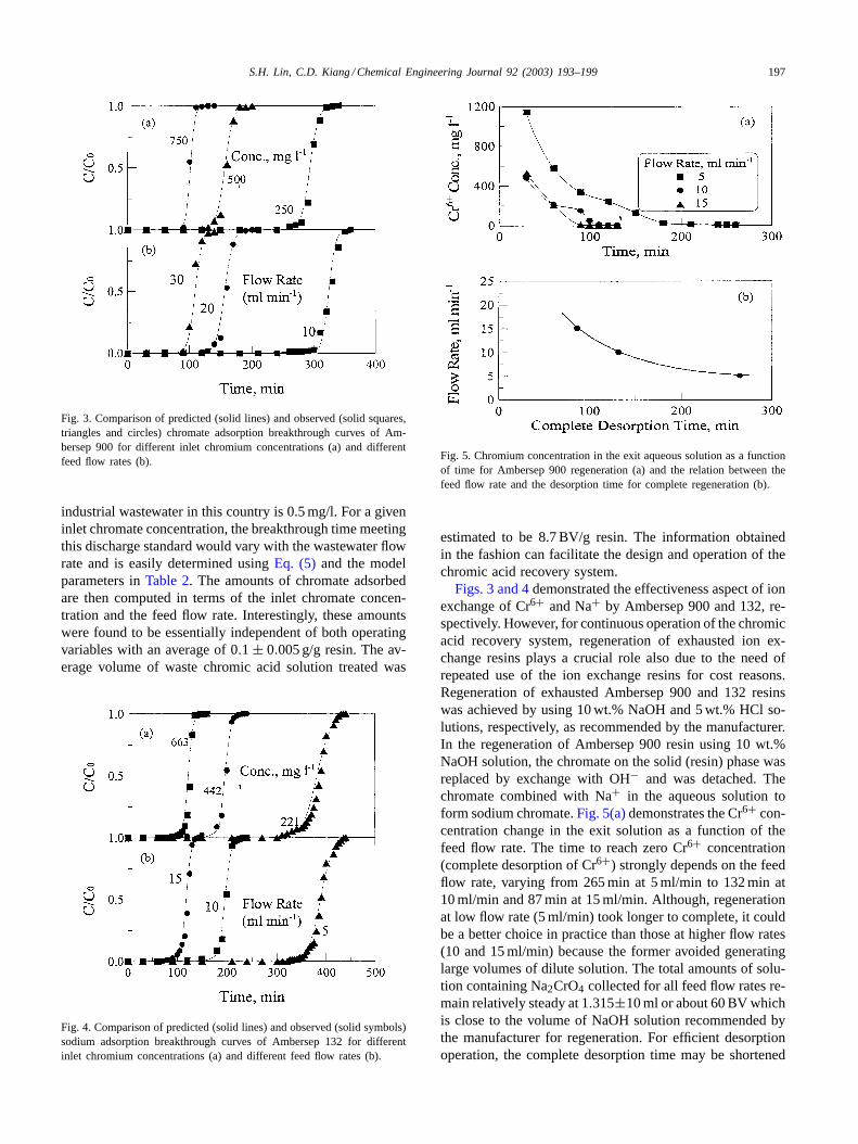
Fig. 3. Comparison of predicted (solid lines) and observed (solid squares,triangles and circles) chromate adsorption breakthrough curves of Am-bersep 900 for different inlet chromium concentrations (a) and differentfeed flow rates (b).
industrial wastewater in this country is 0.5 mg/l. For a giveninlet chromate concentration, the breakthrough time meetingthis discharge standard would vary with the wastewater flowrate and is easily determined usingEq. (5) and the modelparameters inTable 2. The amounts of chromate adsorbedare then computed in terms of the inlet chromate concen-tration and the feed flow rate. Interestingly, these amountswere found to be essentially independent of both operatingvariables with an average of 0.1 ± 0.005 g/g resin. The av-erage volume of waste chromic acid solution treated was
Fig. 4. Comparison of predicted (solid lines) and observed (solid symbols)sodium adsorption breakthrough curves of Ambersep 132 for differentinlet chromium concentrations (a) and different feed flow rates (b).
Fig. 5. Chromium concentration in the exit aqueous solution as a functionof time for Ambersep 900 regeneration (a) and the relation between thefeed flow rate and the desorption time for complete regeneration (b).
estimated to be 8.7 BV/g resin. The information obtainedin the fashion can facilitate the design and operation of thechromic acid recovery system.
Figs. 3 and 4demonstrated the effectiveness aspect of ionexchange of Cr6+ and Na+ by Ambersep 900 and 132, re-spectively. However, for continuous operation of the chromicacid recovery system, regeneration of exhausted ion ex-change resins plays a crucial role also due to the need ofrepeated use of the ion exchange resins for cost reasons.Regeneration of exhausted Ambersep 900 and 132 resinswas achieved by using 10 wt.% NaOH and 5 wt.% HCl so-lutions, respectively, as recommended by the manufacturer.In the regeneration of Ambersep 900 resin using 10 wt.%NaOH solution, the chromate on the solid (resin) phase wasreplaced by exchange with OH− and was detached. Thechromate combined with Na+ in the aqueous solution toform sodium chromate.Fig. 5(a)demonstrates the Cr6+ con-centration change in the exit solution as a function of thefeed flow rate. The time to reach zero Cr6+ concentration(complete desorption of Cr6+) strongly depends on the feedflow rate, varying from 265 min at 5 ml/min to 132 min at10 ml/min and 87 min at 15 ml/min. Although, regenerationat low flow rate (5 ml/min) took longer to complete, it couldbe a better choice in practice than those at higher flow rates(10 and 15 ml/min) because the former avoided generatinglarge volumes of dilute solution. The total amounts of solu-tion containing Na2CrO4 collected for all feed flow rates re-main relatively steady at 1.315±10 ml or about 60 BV whichis close to the volume of NaOH solution recommended bythe manufacturer for regeneration. For efficient desorptionoperation, the complete desorption time may be shortened
198 S.H. Lin, C.D. Kiang / Chemical Engineering Journal 92 (2003) 193–199
to less than 1 h by a further increase in the feed flow rate,as shown inFig. 5(b).
In the regeneration of exhausted Ambersep 132 using5 wt.% HCl solution, the Na+ in the solid phase was re-placed by exchange with H+. Thus, the released Na+ waseluted out of the ion exchange resin column. The opera-tion was found to be highly efficient in the experimentaltests. For example, for a feed flow rate of 10 ml/min, only7 min was needed for complete regeneration of exhaustedAmbersep 132. Such a short regeneration time was consis-tently observed for other feed flow rates. Hence, it can besafely said from the test results that using 5 wt.% HCl solu-tion, regeneration of exhausted Ambersep 132 resin can beefficiently accomplished in less than 10 min.
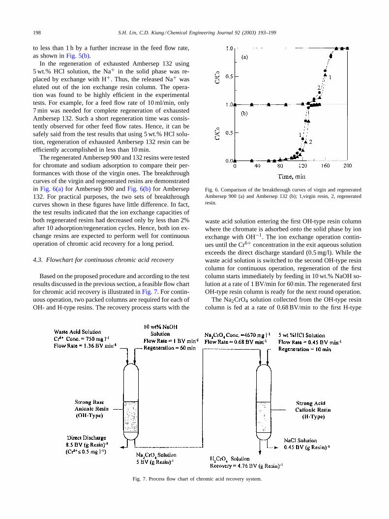
The regenerated Ambersep 900 and 132 resins were testedfor chromate and sodium adsorption to compare their per-formances with those of the virgin ones. The breakthroughcurves of the virgin and regenerated resins are demonstratedin Fig. 6(a)for Ambersep 900 andFig. 6(b) for Ambersep132. For practical purposes, the two sets of breakthroughcurves shown in these figures have little difference. In fact,the test results indicated that the ion exchange capacities ofboth regenerated resins had decreased only by less than 2%after 10 adsorption/regeneration cycles. Hence, both ion ex-change resins are expected to perform well for continuousoperation of chromic acid recovery for a long period.
4.3. Flowchart for continuous chromic acid recovery
Based on the proposed procedure and according to the testresults discussed in the previous section, a feasible flow chartfor chromic acid recovery is illustrated inFig. 7. For contin-uous operation, two packed columns are required for each ofOH- and H-type resins. The recovery process starts with the
Fig. 7. Process flow chart of chromic acid recovery system.
Fig. 6. Comparison of the breakthrough curves of virgin and regeneratedAmbersep 900 (a) and Ambersep 132 (b); 1,virgin resin, 2, regeneratedresin.
waste acid solution entering the first OH-type resin columnwhere the chromate is adsorbed onto the solid phase by ionexchange with OH−1. The ion exchange operation contin-ues until the Cr6+ concentration in the exit aqueous solutionexceeds the direct discharge standard (0.5 mg/l). While thewaste acid solution is switched to the second OH-type resincolumn for continuous operation, regeneration of the firstcolumn starts immediately by feeding in 10 wt.% NaOH so-lution at a rate of 1 BV/min for 60 min. The regenerated firstOH-type resin column is ready for the next round operation.
The Na2CrO4 solution collected from the OH-type resincolumn is fed at a rate of 0.68 BV/min to the first H-type
S.H. Lin, C.D. Kiang / Chemical Engineering Journal 92 (2003) 193–199 199
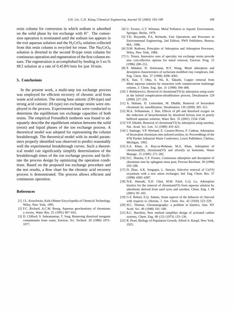
resin column for conversion in which sodium is adsorbedon the solid phase by ion exchange with H+. The conver-sion operation is terminated until the sodium ion appears inthe exit aqueous solution and the H2CrO4 solution collectedfrom this resin column is recycled for reuse. The Na2CrO4solution is diverted to the second H-type resin column forcontinuous operation and regeneration of the first column en-sues. The regeneration is accomplished by feeding in 5 wt.%HCl solution at a rate of 0.45 BV/min for just 10 min.
5. Conclusions
In the present work, a multi-step ion exchange processwas employed for efficient recovery of chromic acid fromwaste acid solution. The strong base anionic (OH-type) andstrong acid cationic (H-type) ion exchange resins were em-ployed in the process. Experimental tests were conducted todetermine the equilibrium ion exchange capacities of bothresins. The empirical Freundlich isotherm was found to ad-equately describe the equilibrium relation between the solid(resin) and liquid phases of the ion exchange process. Atheoretical model was adopted for representing the columnbreakthrough. The theoretical model with its model param-eters properly identified was observed to predict reasonablywell the experimental breakthrough curves. Such a theoret-ical model can significantly simplify determination of thebreakthrough times of the ion exchange process and facili-tate the process design by optimizing the operation condi-tions. Based on the proposed ion exchange procedure andthe test results, a flow chart for the chromic acid recoveryprocess is demonstrated. The process allows efficient andcontinuous operation.
References
[1] J.L. Kroschwitz, Kirk-Othmer Encyclopedia of Chemical Technology,Wiley, New York, 1991.
[2] F.C. Richard, A.C.M. Bourg, Aqueous geochemistry of chromium:a review, Water Res. 25 (1991) 807–816.
[3] D. Clifford, S. Subramanian, T. Sorg, Removing dissolved inorganiccontaminants from water, Environ. Sci. Technol. 20 (1986) 1072–1077.
[4] U. Forstnr, G.T. Wittman, Metal Pollution in Aquatic Environment,Springer, Berlin, 1979.
[5] T.D. Reynolds, P.A. Richards, Unit Operations and Processes inEnvironmental Engineering, 2nd Edition, PWS Publishers, Boston,MA, 1996.
[6] D.M. Ruthven, Principles of Adsorption and Adsorption Processes,Wiley, New York, 1984.
[7] G. Totura, Innovative uses of specialty ion exchange resins providenew cost-effective options for metal removal, Environ. Prog. 15(1996) 208–212.
[8] P. Malakul, D. Srinivasan, H.Y. Wang, Metal adsorption anddesorption characteristics of surfactant-modified clay complexes, Ind.Eng. Chem. Res. 37 (1998) 4296–4301.
[9] K. Tani, T. Ohta, S. Nii, K. Takashi, Copper removal fromdilute aqueous solution by extraction with countercurrent multistagecolumn, J. Chem. Eng. Jpn. 31 (1998) 394–406.
[10] J. Bohdziewicz, Removal of chromium(VI) by adsorption using waterin the hybrid complexation-ultrafiltration process, Desalination 129(2000) 227–235.
[11] A. Hafiane, D. Lemordant, M. Dhahbi, Removal of hexavalentchromium by nanofiltration. Desalination 130 (2000) 305–312.
[12] M.A. Schlautman, J. Han, Effects of pH and dissolved oxygen onthe reduction of hexachromium by dissolved ferrous iron in poorlybuffered aqueous solution, Water Res. 35 (2001) 1534–1546.
[13] V.P. Dikshit, Removal of chromium(VI) by adsorption using sawdust,Nat. Acad. Sci. Lett. 12 (1989) 419–421.
[14] I. Santiago, V.P. Worland, E. Cazares-Rivera, F. Cadena, Adsorptionof hexavalent chromium onto tailored zeolites, in: Proceeddings of the47th Purdue Industrial Waste Conference, Lewis Publishers, Chelsea,Michigan, 1992.
[15] S.A. Khan, A. Riaz-ur-Rehman, M.A. Khan, Adsorption ofchromium(III), chromium(VI) and silver(I) on bentonite, WasteManage. 15 (1995) 271–282.
[16] D.C. Sharma, C.F. Forster, Continuous adsorption and desorption ofchromium ions by sphagnun moss peat, Process Biochem. 30 (1998)293–298.
[17] D. Zhao, A.K. Sengupta, L. Stewart, Selective removal of Cr(VI)oxyanions with a new anion exchanger, Ind. Eng. Chem. Res. 37(1998) 4383–4387.
[18] N.K. Hamadi, X.D. Chen, M.M. Faird, G.Q. Lu, Adsorptionkinetics for the removal of chromium(VI) from aqueous solution byadsorbents derived from used tyres and sawdust, Chem. Eng. J. 84(2001) 95–105.
[19] G.S. Bohart, E.Q. Adams, Some aspects of the behavior of charcoalwith respects to chlorine, J. Am. Chem. Soc. 42 (1920) 523–529.
[20] H.C. Thomas, Chromatography: a problem in kinetics, Ann. NYAcad. Sci. 49 (1948) 161–168.
[21] R.C. Hutchins, New method simplifies design of activated carbonsystems, Chem. Eng. 80 (12) (1973) 133–136.
[22] R. Pearl, Biology of Population Growth, Alfred A. Knopf, New York,1925.


![Lactic Acid Recovery Process by Ion-exchange Resin: Modeling€¦ · acid recovery is proliferating [2-8]. Currently, commercial recovery of lactic acid by ion-exchange resin exists](https://img.pdfslide.us/doc/110x75/5eaa0170ad141e018c21b0d4/lactic-acid-recovery-process-by-ion-exchange-resin-modeling-acid-recovery-is-proliferating.jpg)