Embed Size (px)
Citation preview
Joseph Sharkey 1 Final Report Spring 2007
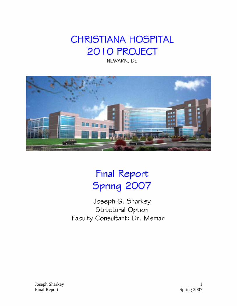
CCHHRRIISSTTIIAANNAA HHOOSSPPIITTAALL 22001100 PPRROOJJEECCTT
NEWARK, DE
FFiinnaall RReeppoorrtt SSpprriinngg 22000077
Joseph G. Sharkey Structural Option
Faculty Consultant: Dr. Memari
Joseph Sharkey 2 Final Report Spring 2007
Joseph Sharkey 3 Final Report Spring 2007
EExxeeccuuttiivvee SSuummmmaarryy
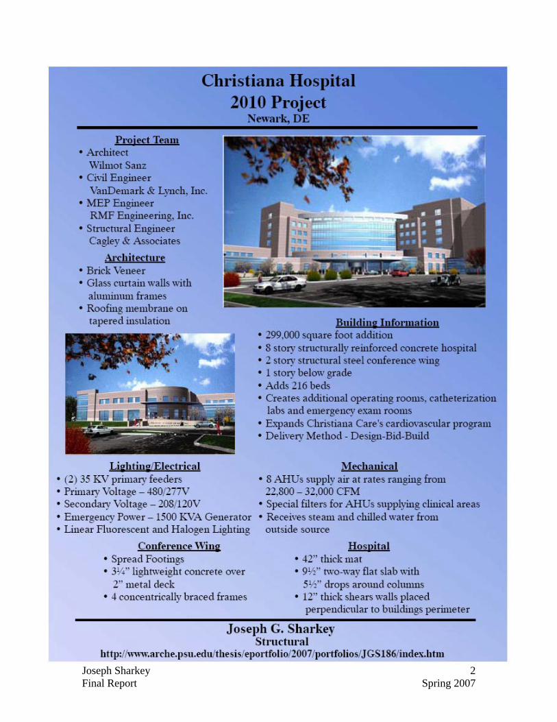
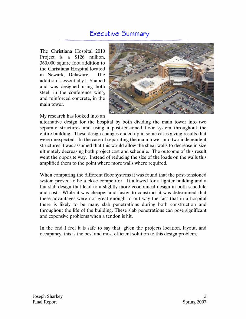
The Christiana Hospital 2010 Project is a $126 million, 360,000 square foot addition to the Christiana Hospital located in Newark, Delaware. The addition is essentially L-Shaped and was designed using both steel, in the conference wing, and reinforced concrete, in the main tower.
My research has looked into an alternative design for the hospital by both dividing the main tower into two separate structures and using a post-tensioned floor system throughout the entire building. These design changes ended up in some cases giving results that were unexpected. In the case of separating the main tower into two independent structures it was assumed that this would allow the shear walls to decrease in size ultimately decreasing both project cost and schedule. The outcome of this result went the opposite way. Instead of reducing the size of the loads on the walls this amplified them to the point where more walls where required. When comparing the different floor systems it was found that the post-tensioned system proved to be a close competitor. It allowed for a lighter building and a flat slab design that lead to a slightly more economical design in both schedule and cost. While it was cheaper and faster to construct it was determined that these advantages were not great enough to out way the fact that in a hospital there is likely to be many slab penetrations during both construction and throughout the life of the building. These slab penetrations can pose significant and expensive problems when a tendon is hit. In the end I feel it is safe to say that, given the projects location, layout, and occupancy, this is the best and most efficient solution to this design problem.
Joseph Sharkey 4 Final Report Spring 2007
TTaabbllee ooff CCoonntteennttss
Cover -------------------------------------------- 1 Abstract ----------------------------------------- 2
Executive Summary ----------------------------- 3 Table of Contents ------------------------------ 4 Introduction ------------------------------------- 6 Existing Structure ------------------------------ 7
Foundation 8 Columns 8 Floor System 8 Lateral Force Resisting System 10 Roof System 11
Proposed Structural Design ------------------ 12 Codes & Loading Cases ----------------------- 14
Gravity Loading --------------------------------- 15 Wind Loading ----------------------------------- 16 Seismic Loading ------------------------------- 23 Shear Wall Design ----------------------------- 25
Main Tower 25 Conference Wing 31
Joseph Sharkey 5 Final Report Spring 2007
Post-Tensioned Design ----------------------- 33 Two-Way Slab (Main Tower) 33 One-Way Slab and Beams (Conference Wing) 40
Column Design --------------------------------- 42 Impact on Foundations ----------------------- 43 Construction Management Breadth -------- 44 Acoustics Breadth ---------------------------- 48 Conclusions ----------------------------------- 49 Acknowledgements -------------------------- 50 Appendix A ----------------------------------- 51 Appendix B ----------------------------------- 76 Appendix C ----------------------------------- 90 Appendix D ----------------------------------- 99
Joseph Sharkey 6 Final Report Spring 2007
IInnttrroodduuccttiioonn
The Christiana Hospital 2010 Project is a $126 million, 360,000 square foot addition to the Christiana Hospital located in Newark, Delaware. This addition includes the Bank of America Pavilion and the John H. Ammon Medical Education Center which creates additional operating rooms, catheterization labs, emergency exam rooms, and 216 beds for patients. It will also expand Christiana Care’s cardiovascular program and create an education center in partnership with the Delaware Academy of Medicine. Christiana Care is one of the region’s largest not-for-profit health care providers, serving Delaware as well as areas of Maryland, Pennsylvania and New Jersey.
For the past eight months I have been researching, analyzing, and redesigning the Christiana Hospital 2010 Project in search of the most efficient and cost effective structural system. The system which I will be comparing to the original structural design is in two parts. My first change to the building will involve making the building more symmetrical for lateral, wind, and seismic loading by sectioning the main tower into two separate structures separated by an expansion joint. This design change will hopefully reduce the torsional effects of lateral load and in turn allow the shear walls to be sized smaller and/or require less total shear walls decreasing the projects schedule and cost.
Secondly I will compare the existing structure to a structure using a two-way post-tensioned slab in the main tower and one-way post-tensioned beams and slab in the conference wing. Due to this change in the conference wing I will also make the necessary design changes to the rest of the wing which include reinforced concrete columns and reinforced concrete shear walls. Once all these structural changes have been made I will compare the existing structure with my new design using the criteria of length of schedule, practicality, and final cost.
In addition to these changes I will also do an acoustical breadth. This breadth will look at the design of the major conference room in the conference wing from the perspective of acoustics. I will look into what materials have been used to cover the walls, ceilings, and floors, and using this information will perform sound reverberation and sound transmission loss checks. With my results I will suggest any necessary changes that could be made to improve the room acoustically.
Joseph Sharkey 7 Final Report Spring 2007
EExxiissttiinngg SSttrruuccttuurree
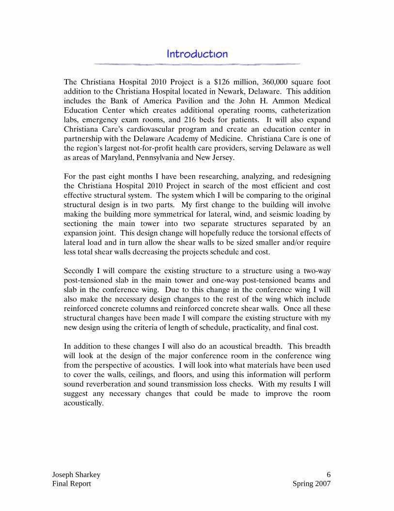
The Christiana Hospital is mainly composed of structurally reinforced concrete with a stand alone adjacent steel framed conference wing. The concrete portion of the building stands 8 stories with one level underground and a penthouse roof. The structure contains varying spans which are created using a typical 9½ inch thick two-way flat slab with 5½ inch drops or shear caps. This slab transfers load to 24 inch square columns which in turn take the load down to a mat foundation. To prevent rotation and lateral displacement due to wind or seismic loading shear walls are strategically placed perpendicular to the buildings perimeter. The conference wing is a 3 story structural steel frame with a majority of beams having pinned connections and spanning around 30 feet. In the center of this area is a larger span of over 60 feet. The buildings loads are transferred to the beams using a 3¼ inch, light weight concrete, structural slab over a 2 inch deep by 18 gage galvanized composite metal deck creating a total slab thickness of 5¼ inches. The load in the beams is transferred to steel girders which are attached using a pinned connection to W-shaped columns. These columns continue down to 4000psi concrete spread footings. The wind and seismic loading in this area is distributed using concentrically braced frames.
Joseph Sharkey 8 Final Report Spring 2007
Foundation: The building consists of two separate types of foundations. In the concrete tower area the building rests on a 42” thick mat foundation. This mat is reinforced with #9’s at 12” o.c. each way, top and bottom, with additional reinforcing added where needed. In the area of the conference wing, steel columns rest on concrete spread footings. These footings range in size from 4’x4’x 15” deep up to 16’x16’x 48” deep. The allowable soil bearing pressure for this site is 4000psf.
Applications Concrete Strengths (f’c)
Footings 4000 psi
Mat Foundation 6000 psi
Grade Beams 4000 psi
Slab-On-Grade 3500 psi Columns: In the tower area a majority of the columns are 24”x24” reinforced concrete columns with only a few occurrences of 12”x24” columns. At the eighth floor nearly all the concrete columns stop and off of them W8 steel columns are posted. The 3 story conference wing is composed of W10 and W12 steel columns.
Applications Material Steel Columns ASTM A992, Grade 50
Concrete Columns (Below Third Floor)
5000 psi
Concrete Columns (Above Third Floor)
4000 psi
Floor System: Throughout the tower, spans are accomplished using 9½” thick two-way flat slabs with typical 5½” drops or shear caps at each column. Reinforcement for the slabs varies throughout the building. The conference area uses a completely separate type of floor system. Here steel girders span between columns in one direction while beams, spanning in the opposite direction, frame into the girders. This steel framework works in composite action with the floor slab placed on top. The slab is constructed of 3¼” lightweight concrete over a 2” deep x 18 gage galvanized composite metal deck. The slab is then reinforced with 6x6-W2.1xW2.1 WWF. The bulk of the
Joseph Sharkey 9 Final Report Spring 2007
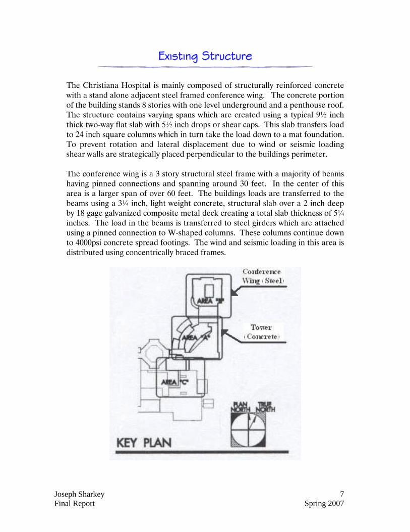
spans vary anywhere from 20 to 40 feet. Although, running across the middle, is a large 63 foot span made possible using W30x90 beams and the composite action.
Steel Wing
Concrete Tower
Joseph Sharkey 10 Final Report Spring 2007
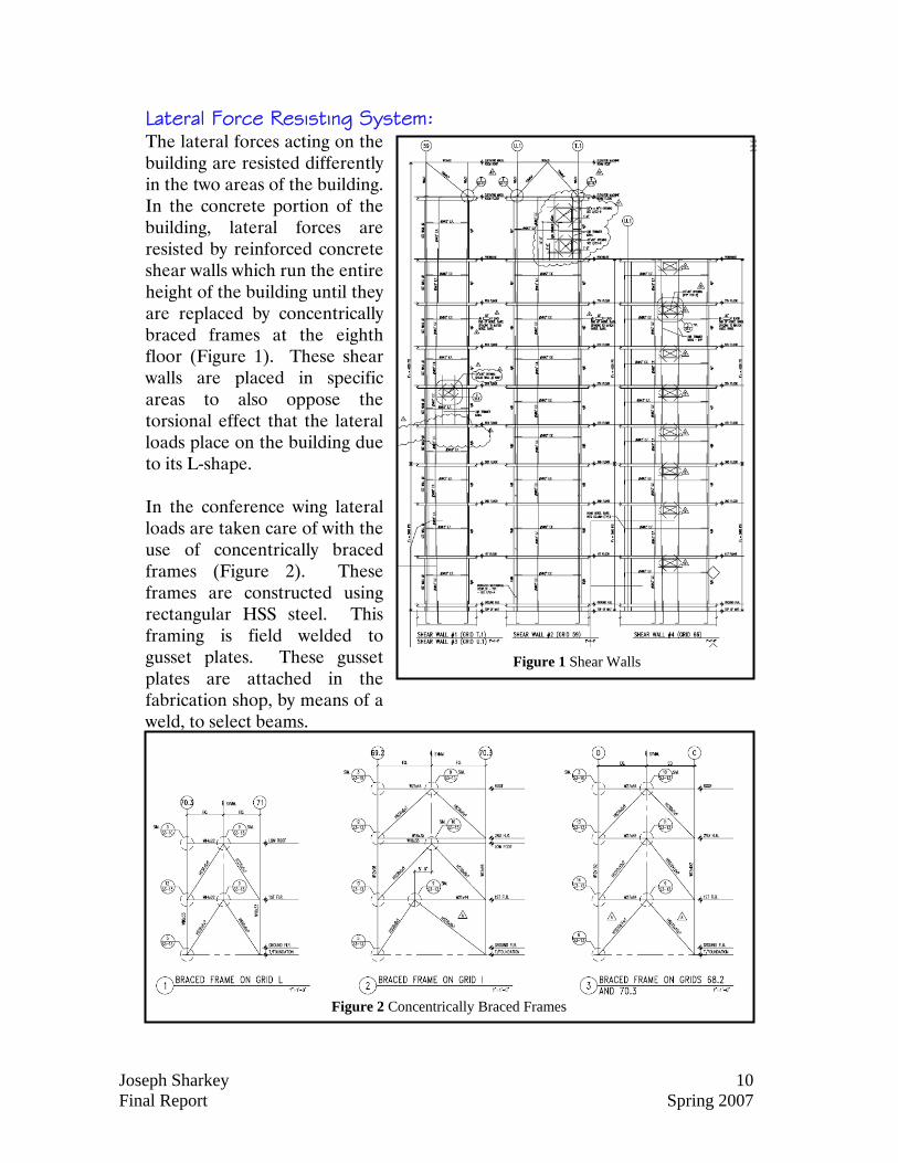
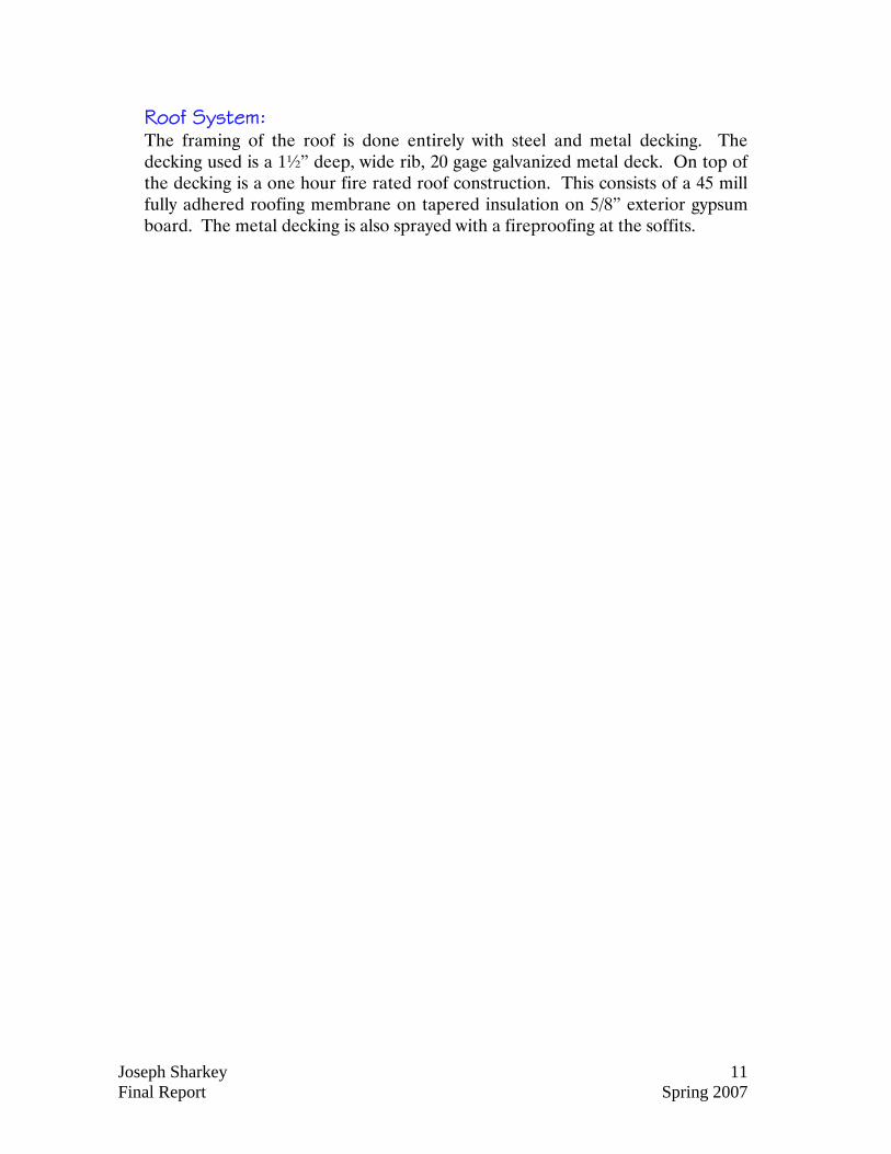
Lateral Force Resisting System: The lateral forces acting on the building are resisted differently in the two areas of the building. In the concrete portion of the building, lateral forces are resisted by reinforced concrete shear walls which run the entire height of the building until they are replaced by concentrically braced frames at the eighth floor (Figure 1). These shear walls are placed in specific areas to also oppose the torsional effect that the lateral loads place on the building due to its L-shape. In the conference wing lateral loads are taken care of with the use of concentrically braced frames (Figure 2). These frames are constructed using rectangular HSS steel. This framing is field welded to gusset plates. These gusset plates are attached in the fabrication shop, by means of a weld, to select beams.
Figure 2 Concentrically Braced Frames
Figure 1 Shear Walls
Joseph Sharkey 11 Final Report Spring 2007
Roof System: The framing of the roof is done entirely with steel and metal decking. The decking used is a 1½” deep, wide rib, 20 gage galvanized metal deck. On top of the decking is a one hour fire rated roof construction. This consists of a 45 mill fully adhered roofing membrane on tapered insulation on 5/8” exterior gypsum board. The metal decking is also sprayed with a fireproofing at the soffits.
Joseph Sharkey 12 Final Report Spring 2007
PPrrooppoosseedd SSttrruuccttuurraall DDeessiiggnn
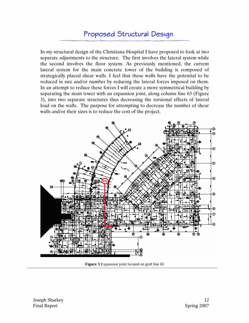
In my structural design of the Christiana Hospital I have proposed to look at two separate adjustments to the structure. The first involves the lateral system while the second involves the floor system. As previously mentioned, the current lateral system for the main concrete tower of the building is composed of strategically placed shear walls. I feel that these walls have the potential to be reduced in size and/or number by reducing the lateral forces imposed on them. In an attempt to reduce these forces I will create a more symmetrical building by separating the main tower with an expansion joint, along column line 65 (Figure 3), into two separate structures thus decreasing the torsional effects of lateral load on the walls. The purpose for attempting to decrease the number of shear walls and/or their sizes is to reduce the cost of the project.
Figure 3 Expansion joint located on grid line 65
Joseph Sharkey 13 Final Report Spring 2007
My second design change is to change all the floor systems in the structure, including the conference wing, to post-tensioned concrete. Having completed an analysis of alternate floor systems (Refer to Technical Report #2) it is obvious that the only types of floor systems economical enough to be used for the main tower area are two-way systems. Being that the current floor system is a two-way reinforced concrete slab with drop panels at the columns the best alternative to compare with it is a two-way post-tensioned concrete slab. This slab design will hopefully allow for the deletion of the drop panels which can potentially reduce both the project schedule and the project cost by reducing the complexity of the formwork. To change the conference wing (currently steel) to post-tensioned concrete, a design using one-way post-tensioned slabs and beams has been chosen due to the length of the spans. As a result of this change the columns in the building will also be redesigned as concrete and the lateral force resisting system will be changed from concentrically braced frames to reinforced concrete shear walls. After designing all of the changes mentioned above both a schedule and a cost analysis will be performed comparing the existing design with my proposed design.
Joseph Sharkey 14 Final Report Spring 2007
CCooddeess && LLooaaddiinngg CCaasseess
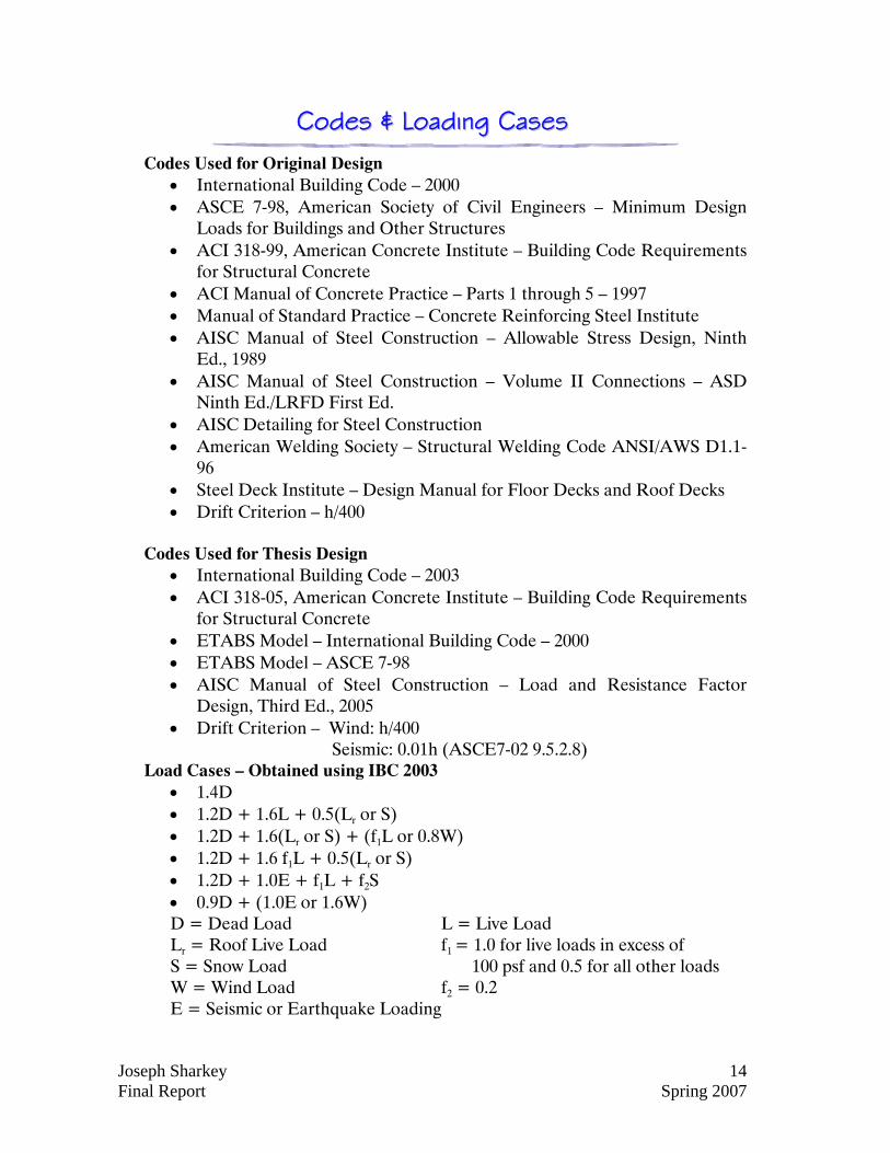
Codes Used for Original Design
• International Building Code – 2000 • ASCE 7-98, American Society of Civil Engineers – Minimum Design
Loads for Buildings and Other Structures • ACI 318-99, American Concrete Institute – Building Code Requirements
for Structural Concrete • ACI Manual of Concrete Practice – Parts 1 through 5 – 1997 • Manual of Standard Practice – Concrete Reinforcing Steel Institute • AISC Manual of Steel Construction – Allowable Stress Design, Ninth
Ed., 1989 • AISC Manual of Steel Construction – Volume II Connections – ASD
Ninth Ed./LRFD First Ed. • AISC Detailing for Steel Construction • American Welding Society – Structural Welding Code ANSI/AWS D1.1-
96 • Steel Deck Institute – Design Manual for Floor Decks and Roof Decks • Drift Criterion – h/400
Codes Used for Thesis Design
• International Building Code – 2003 • ACI 318-05, American Concrete Institute – Building Code Requirements
for Structural Concrete • ETABS Model – International Building Code – 2000 • ETABS Model – ASCE 7-98 • AISC Manual of Steel Construction – Load and Resistance Factor
Design, Third Ed., 2005 • Drift Criterion – Wind: h/400
Seismic: 0.01h (ASCE7-02 9.5.2.8) Load Cases – Obtained using IBC 2003
• 1.4D • 1.2D + 1.6L + 0.5(Lr or S) • 1.2D + 1.6(Lr or S) + (f1L or 0.8W) • 1.2D + 1.6 f1L + 0.5(Lr or S) • 1.2D + 1.0E + f1L + f2S • 0.9D + (1.0E or 1.6W) D = Dead Load L = Live Load Lr = Roof Live Load f1 = 1.0 for live loads in excess of S = Snow Load 100 psf and 0.5 for all other loads W = Wind Load f2 = 0.2 E = Seismic or Earthquake Loading
Joseph Sharkey 15 Final Report Spring 2007
Gravity Loading
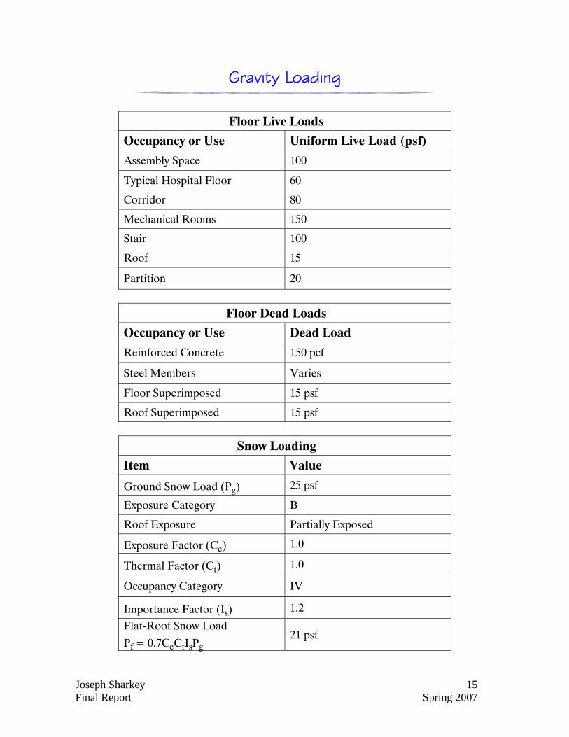
Floor Live Loads
Occupancy or Use Uniform Live Load (psf)
Assembly Space 100
Typical Hospital Floor 60
Corridor 80
Mechanical Rooms 150
Stair 100
Roof 15
Partition 20
Floor Dead Loads
Occupancy or Use Dead Load
Reinforced Concrete 150 pcf
Steel Members Varies
Floor Superimposed 15 psf
Roof Superimposed 15 psf
Snow Loading
Item Value
Ground Snow Load (Pg) 25 psf
Exposure Category B
Roof Exposure Partially Exposed
Exposure Factor (Ce) 1.0
Thermal Factor (Ct) 1.0
Occupancy Category IV
Importance Factor (Is) 1.2
Flat-Roof Snow Load
Pf = 0.7CeCtIsPg 21 psf
Joseph Sharkey 16 Final Report Spring 2007
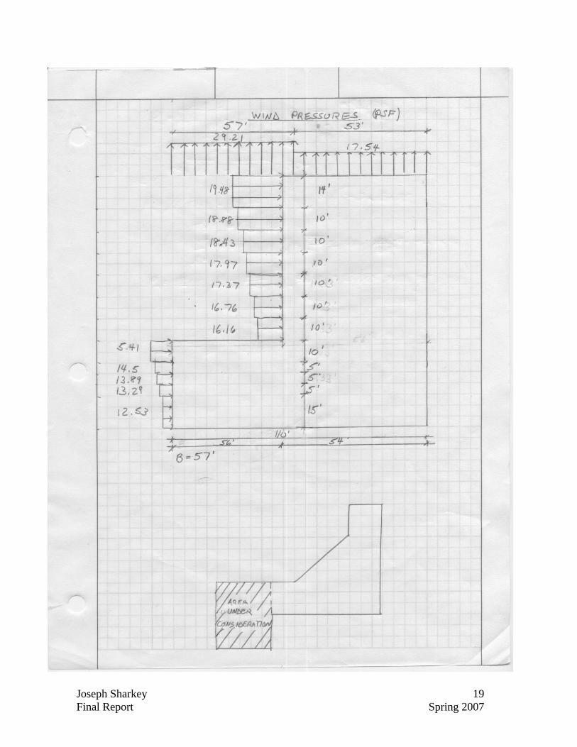
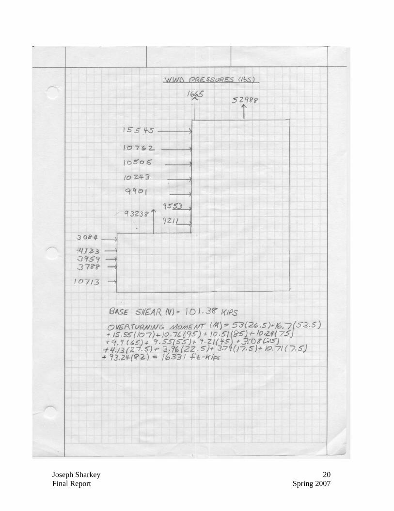
WWiinndd LLooaaddiinngg
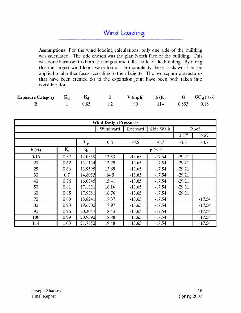
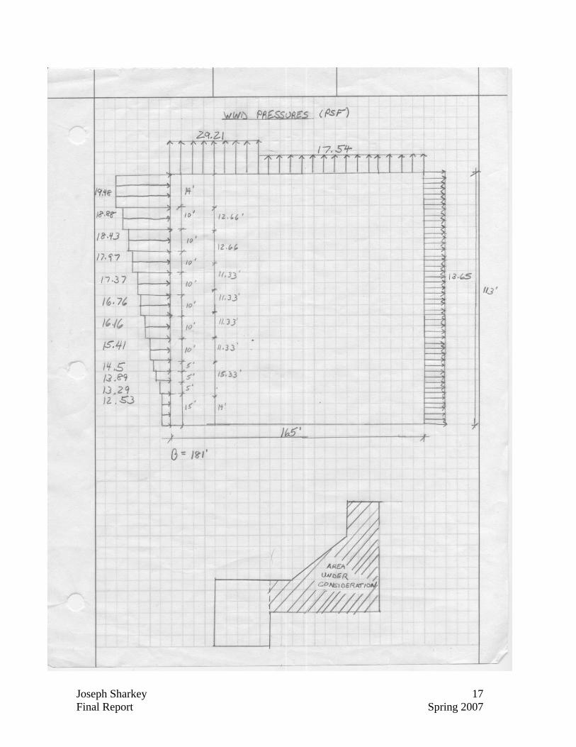
Assumptions: For the wind loading calculations, only one side of the building was calculated. The side chosen was the plan North face of the building. This was done because it is both the longest and tallest side of the building. By doing this the largest wind loads were found. For simplicity these loads will then be applied to all other faces according to their heights. The two separate structures that have been created do to the expansion joint have been both taken into consideration.
Exposure Category Kzt Kd I V (mph) h (ft) G GCpi (+/-)
B 1 0.85 1.2 90 114 0.893 0.18
Windward Leeward Side Walls0-57' >57'
Cp 0.8 -0.5 -0.7 -1.3 -0.7
h (ft) Kz qz
0-15 0.57 12.0559 12.53 -13.65 -17.54 -29.2120 0.62 13.1134 13.29 -13.65 -17.54 -29.2125 0.66 13.9595 13.89 -13.65 -17.54 -29.2130 0.7 14.8055 14.5 -13.65 -17.54 -29.2140 0.76 16.0745 15.41 -13.65 -17.54 -29.2150 0.81 17.1321 16.16 -13.65 -17.54 -29.2160 0.85 17.9781 16.76 -13.65 -17.54 -29.2170 0.89 18.8241 17.37 -13.65 -17.54 -17.5480 0.93 19.6702 17.97 -13.65 -17.54 -17.5490 0.96 20.3047 18.43 -13.65 -17.54 -17.54
100 0.99 20.9392 18.88 -13.65 -17.54 -17.54114 1.03 21.7852 19.48 -13.65 -17.54 -17.54
Roof
p (psf)
Wind Design Pressures
Joseph Sharkey 17 Final Report Spring 2007
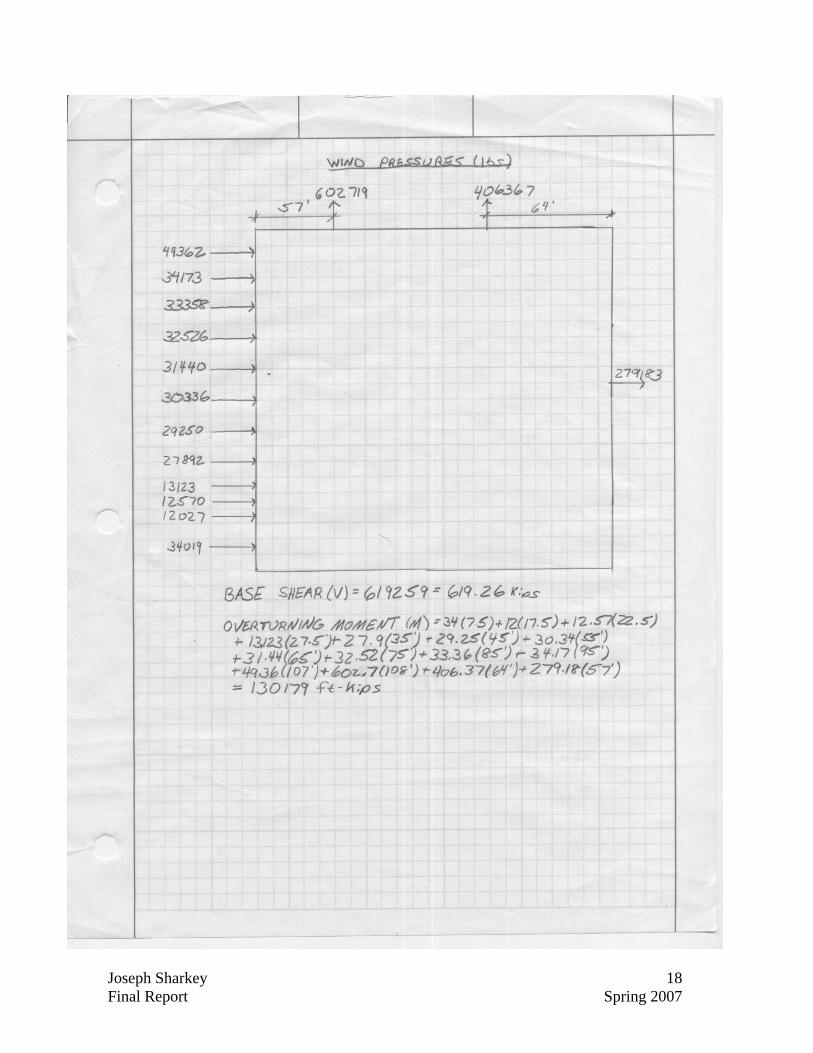
Joseph Sharkey 18 Final Report Spring 2007
Joseph Sharkey 19 Final Report Spring 2007
Joseph Sharkey 20 Final Report Spring 2007
Joseph Sharkey 21 Final Report Spring 2007
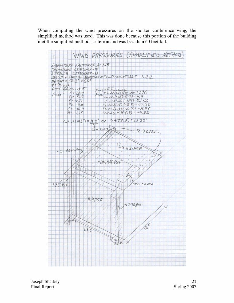
When computing the wind pressures on the shorter conference wing, the simplified method was used. This was done because this portion of the building met the simplified methods criterion and was less than 60 feet tall.
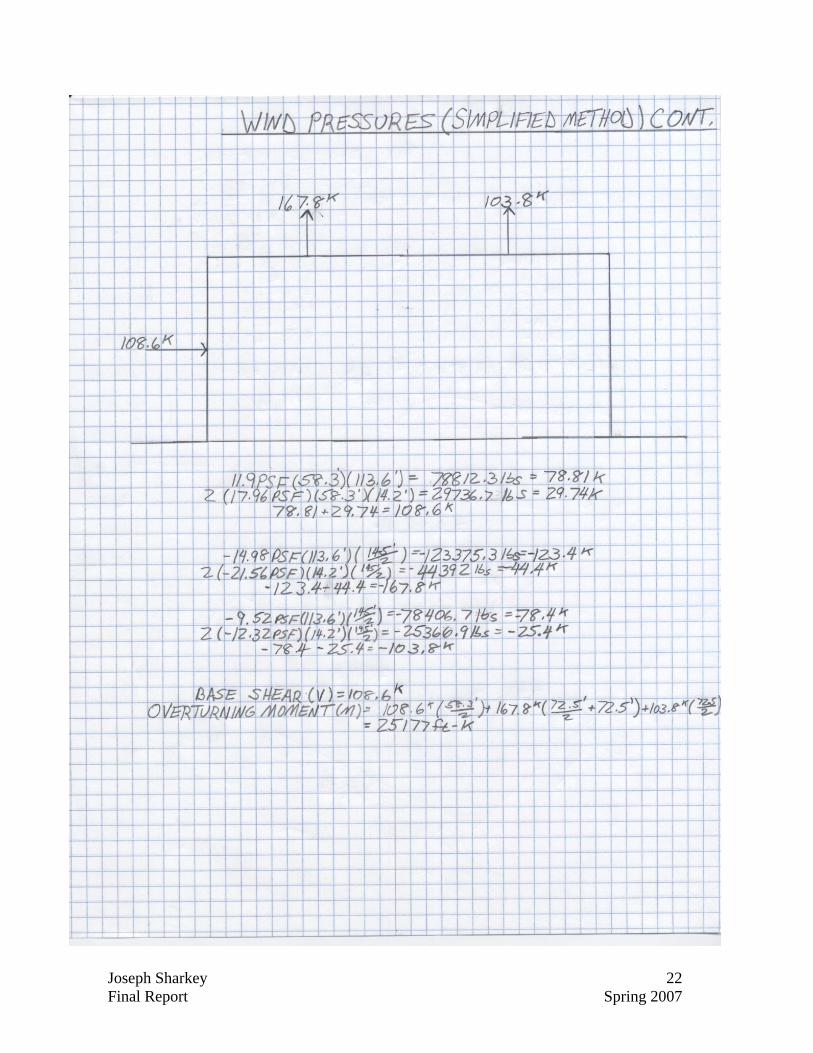
Joseph Sharkey 22 Final Report Spring 2007
Joseph Sharkey 23 Final Report Spring 2007
B
A
C
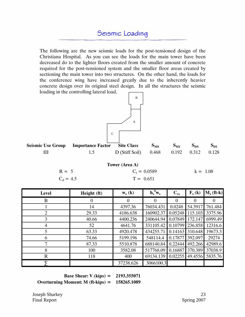
Seismic Loading
The following are the new seismic loads for the post-tensioned design of the Christiana Hospital. As you can see the loads for the main tower have been decreased do to the lighter floors created from the smaller amount of concrete required for the post-tensioned system and the smaller floor areas created by sectioning the main tower into two structures. On the other hand, the loads for the conference wing have increased greatly due to the inherently heavier concrete design over its original steel design. In all the structures the seismic loading in the controlling lateral load.
Seismic Use Group Importance Factor Site Class SMS SM1 SDS SD1
III 1.5 D (Stiff Soil) 0.468 0.192 0.312 0.128
R = 5 Cs = 0.0589 k = 1.08
Cd = 4.5 T = 0.651
Level Height (ft) wx (k) hxkwx Cvx Fx (k) Mx (ft-k)
B 0 0 0 0 0 01 14 4397.36 76034.431 0.0248 54.3917 761.4842 29.33 4186.638 160902.37 0.05248 115.103 3375.963 40.66 4400.236 240644.94 0.07849 172.147 6999.494 52 4641.76 331105.42 0.10799 236.858 12316.65 63.33 4920.478 434255.71 0.14163 310.648 19673.36 74.66 5199.196 548114.4 0.17877 392.097 292747 87.33 5510.878 688140.84 0.22444 492.266 42989.68 100 3582.08 517768.09 0.16887 370.389 37038.9R 118 400 69134.139 0.02255 49.4556 5835.76∑ 37238.626 3066100.3
2193.355071158265.1089
Tower (Area A)
Base Shear: V (kips) = Overturning Moment: M (ft-kips) =
Joseph Sharkey 24 Final Report Spring 2007
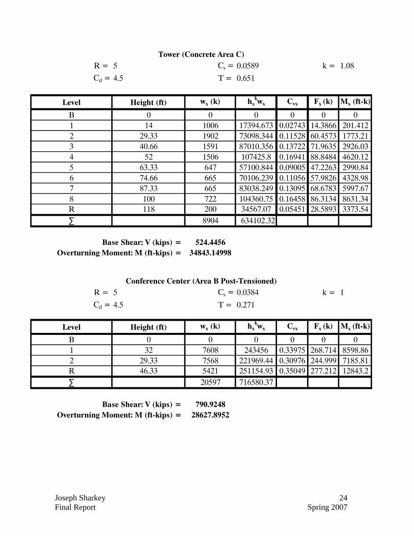
R = 5 Cs = 0.0589 k = 1.08
Cd = 4.5 T = 0.651
Level Height (ft) wx (k) hxkwx Cvx Fx (k) Mx (ft-k)
B 0 0 0 0 0 01 14 1006 17394.673 0.02743 14.3866 201.4122 29.33 1902 73098.344 0.11528 60.4573 1773.213 40.66 1591 87010.356 0.13722 71.9635 2926.034 52 1506 107425.8 0.16941 88.8484 4620.125 63.33 647 57100.844 0.09005 47.2263 2990.846 74.66 665 70106.239 0.11056 57.9826 4328.987 87.33 665 83038.249 0.13095 68.6783 5997.678 100 722 104360.75 0.16458 86.3134 8631.34R 118 200 34567.07 0.05451 28.5893 3373.54∑ 8904 634102.32
524.445634843.14998
Tower (Concrete Area C)
Base Shear: V (kips) = Overturning Moment: M (ft-kips) =
R = 5 Cs = 0.0384 k = 1
Cd = 4.5 T = 0.271
Level Height (ft) wx (k) hxkwx Cvx Fx (k) Mx (ft-k)
B 0 0 0 0 0 01 32 7608 243456 0.33975 268.714 8598.862 29.33 7568 221969.44 0.30976 244.999 7185.81R 46.33 5421 251154.93 0.35049 277.212 12843.2∑ 20597 716580.37
790.924828627.8952
Conference Center (Area B Post-Tensioned)
Base Shear: V (kips) = Overturning Moment: M (ft-kips) =
Joseph Sharkey 25 Final Report Spring 2007
SShheeaarr WWaallll DDeessiiggnn
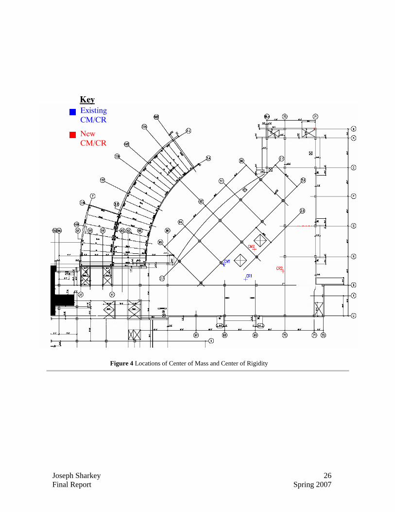
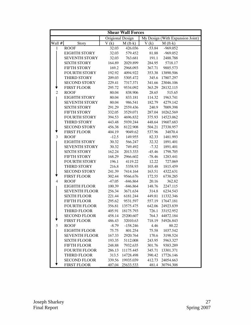
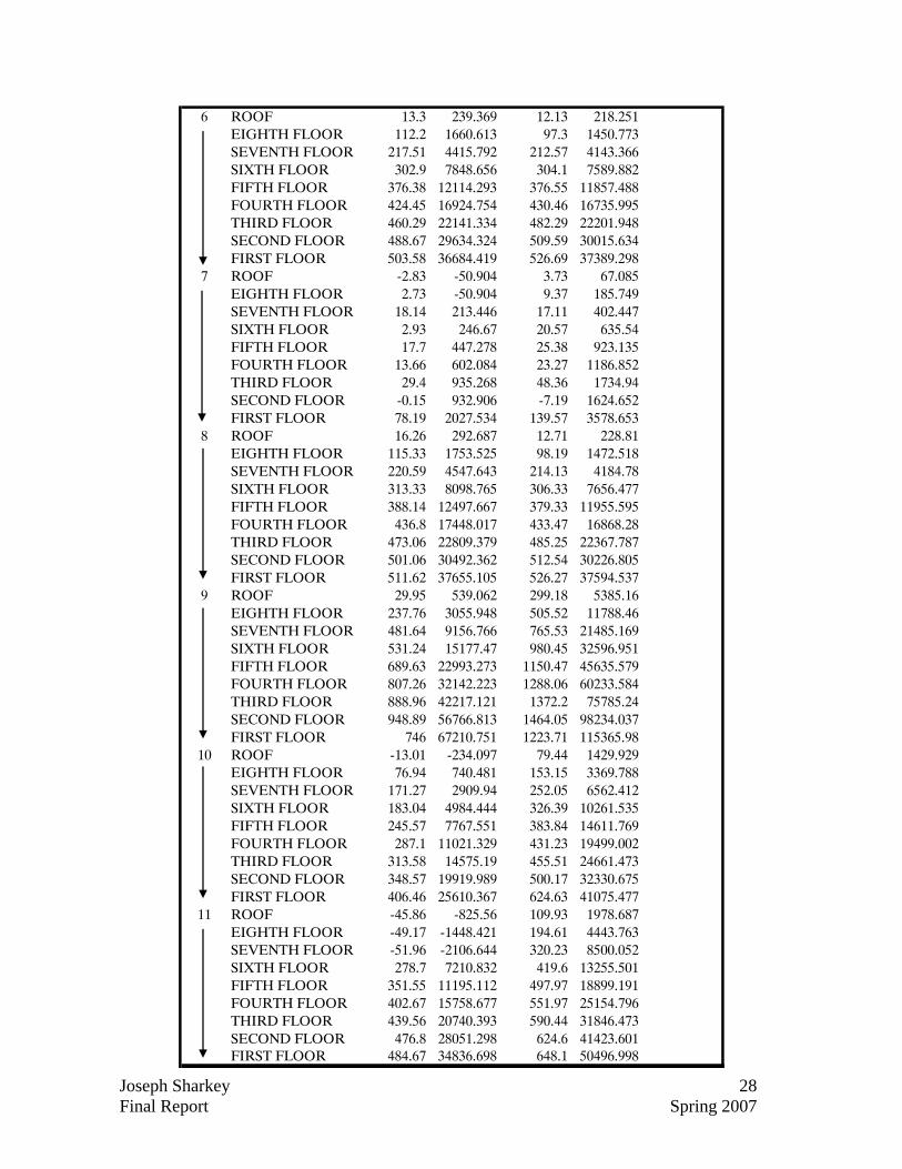
Main Tower: As stated earlier the purpose of my lateral design is to attempt to reduce the number or size of shear walls in order to decrease the project’s cost and/or schedule. The approach taken to try and achieve this goal was by minimizing the lateral load on the structure by sectioning the tower at column line 65 with an expansion joint. The theory behind this idea was that by creating two independent and more symmetrical structures the center of mass and the center of rigidity would move closer to one another and decrease the forces in the shear walls due to torsional effects. In my analysis of the shear walls the loads had first been determined on each wall before the structure was separated and then recomputed for the separated structures using ETABS. The results found were actually different than what I had been trying to achieve. Because the controlling lateral force was seismic, the equivalent lateral forces on each floor of the building were a function of the buildings mass. In my design the mass of each floor was lighter due to two separate factors. The first was the lighter post-tensioned slabs which, although were a ½” thicker, required no drop panels at the columns. The second factor was that due to the expansion joint the floor area required to be restrained was less. With the building mass being reduced the equivalent lateral load on the building was also reduced but in the end the load on each individual wall was increased. This increased load was caused because the eccentricities were actually increased (see Figure 4 below) and, although the equivalent lateral forces were decreased, there were now less shear wall in place to resist the load. The combination of all these factors resulted in larger forces in the shear walls and ultimately forced me to add a total of 7 walls, 3 in Area A and 4 in Area B. The forces in each wall and their resulting deflections can be seen below.
Joseph Sharkey 26 Final Report Spring 2007
Figure 4 Locations of Center of Mass and Center of Rigidity
Existing CM/CR
New CM/CR
Key
Joseph Sharkey 27 Final Report Spring 2007
Wall # Story V (k) M (ft-k) V (k) M (ft-k)1 ROOF 32.03 426.036 -53.84 -969.052
EIGHTH STORY 32.03 579.452 81.88 -969.052SEVENTH STORY 32.03 763.681 191.1 2488.788SIXTH STORY 164.89 2029.899 284.95 5718.17FIFTH STORY 169.2 2968.093 367.71 9885.573FOURTH STORY 192.92 4094.922 353.38 13890.506THIRD STORY 209.03 5305.472 345.6 17807.297SECOND STORY 229.41 7317.371 341.66 23046.106FIRST FLOOR 295.72 9534.092 363.29 28132.115
2 ROOF 80.04 838.906 28.65 515.65EIGHTH STORY 80.04 833.181 114.32 1963.741SEVENTH STORY 80.04 986.541 182.79 4279.142SIXTH STORY 291.29 2559.436 240.9 7009.398FIFTH STORY 332.05 3529.071 287.04 10262.569FOURTH STORY 394.53 4696.832 375.93 14523.062THIRD STORY 443.48 5939.244 448.64 19607.683SECOND STORY 456.38 8122.908 504.21 27338.957FIRST FLOOR 404.19 9049.62 537.96 34870.4
3 ROOF -12.5 149.955 82.33 1481.993EIGHTH STORY 30.32 566.247 32.32 1891.401SEVENTH STORY 30.32 749.492 -7.32 1891.401SIXTH STORY 162.24 2013.333 -45.46 1798.705FIFTH STORY 168.29 2966.602 -78.46 1283.441FOURTH STORY 196.1 4119.22 12.22 727.069THIRD STORY 216.8 5358.93 103.48 1815.459SECOND STORY 241.39 7414.164 163.51 4322.631FIRST FLOOR 302.44 9566.676 172.55 6738.285
4 ROOF -47.05 -846.864 20.16 362.82EIGHTH FLOOR 100.39 -846.864 148.76 2247.115SEVENTH FLOOR 256.34 3671.634 314.8 6234.543SIXTH FLOOR 221.44 6181.244 449.81 11332.346FIFTH FLOOR 295.62 9531.597 557.19 17647.181FOURTH FLOOR 356.81 13575.475 642.06 24923.839THIRD FLOOR 405.91 18175.793 726.1 33152.952SECOND FLOOR 458.14 25200.607 764.3 44872.184FIRST FLOOR 486.43 32010.63 718.19 54926.843
5 ROOF -8.79 -158.246 4.46 80.22EIGHTH FLOOR 75.75 801.254 75.58 1037.542SEVENTH FLOOR 167.33 2920.764 170.6 3198.524SIXTH FLOOR 193.35 5112.008 243.95 5963.327FIFTH FLOOR 248.88 7932.635 301.76 9383.289FOURTH FLOOR 286.13 11175.445 345.71 13301.371THIRD FLOOR 313.5 14728.498 390.42 17726.146SECOND FLOOR 339.56 19935.039 412.73 24054.663FIRST FLOOR 407.04 25633.533 481.4 30794.308
Shear Wall ForcesOrigional Design My Design (With Expansion Joint)
Joseph Sharkey 28 Final Report Spring 2007
6 ROOF 13.3 239.369 12.13 218.251EIGHTH FLOOR 112.2 1660.613 97.3 1450.773SEVENTH FLOOR 217.51 4415.792 212.57 4143.366SIXTH FLOOR 302.9 7848.656 304.1 7589.882FIFTH FLOOR 376.38 12114.293 376.55 11857.488FOURTH FLOOR 424.45 16924.754 430.46 16735.995THIRD FLOOR 460.29 22141.334 482.29 22201.948SECOND FLOOR 488.67 29634.324 509.59 30015.634FIRST FLOOR 503.58 36684.419 526.69 37389.298
7 ROOF -2.83 -50.904 3.73 67.085EIGHTH FLOOR 2.73 -50.904 9.37 185.749SEVENTH FLOOR 18.14 213.446 17.11 402.447SIXTH FLOOR 2.93 246.67 20.57 635.54FIFTH FLOOR 17.7 447.278 25.38 923.135FOURTH FLOOR 13.66 602.084 23.27 1186.852THIRD FLOOR 29.4 935.268 48.36 1734.94SECOND FLOOR -0.15 932.906 -7.19 1624.652FIRST FLOOR 78.19 2027.534 139.57 3578.653
8 ROOF 16.26 292.687 12.71 228.81EIGHTH FLOOR 115.33 1753.525 98.19 1472.518SEVENTH FLOOR 220.59 4547.643 214.13 4184.78SIXTH FLOOR 313.33 8098.765 306.33 7656.477FIFTH FLOOR 388.14 12497.667 379.33 11955.595FOURTH FLOOR 436.8 17448.017 433.47 16868.28THIRD FLOOR 473.06 22809.379 485.25 22367.787SECOND FLOOR 501.06 30492.362 512.54 30226.805FIRST FLOOR 511.62 37655.105 526.27 37594.537
9 ROOF 29.95 539.062 299.18 5385.16EIGHTH FLOOR 237.76 3055.948 505.52 11788.46SEVENTH FLOOR 481.64 9156.766 765.53 21485.169SIXTH FLOOR 531.24 15177.47 980.45 32596.951FIFTH FLOOR 689.63 22993.273 1150.47 45635.579FOURTH FLOOR 807.26 32142.223 1288.06 60233.584THIRD FLOOR 888.96 42217.121 1372.2 75785.24SECOND FLOOR 948.89 56766.813 1464.05 98234.037FIRST FLOOR 746 67210.751 1223.71 115365.98
10 ROOF -13.01 -234.097 79.44 1429.929EIGHTH FLOOR 76.94 740.481 153.15 3369.788SEVENTH FLOOR 171.27 2909.94 252.05 6562.412SIXTH FLOOR 183.04 4984.444 326.39 10261.535FIFTH FLOOR 245.57 7767.551 383.84 14611.769FOURTH FLOOR 287.1 11021.329 431.23 19499.002THIRD FLOOR 313.58 14575.19 455.51 24661.473SECOND FLOOR 348.57 19919.989 500.17 32330.675FIRST FLOOR 406.46 25610.367 624.63 41075.477
11 ROOF -45.86 -825.56 109.93 1978.687EIGHTH FLOOR -49.17 -1448.421 194.61 4443.763SEVENTH FLOOR -51.96 -2106.644 320.23 8500.052SIXTH FLOOR 278.7 7210.832 419.6 13255.501FIFTH FLOOR 351.55 11195.112 497.97 18899.191FOURTH FLOOR 402.67 15758.677 551.97 25154.796THIRD FLOOR 439.56 20740.393 590.44 31846.473SECOND FLOOR 476.8 28051.298 624.6 41423.601FIRST FLOOR 484.67 34836.698 648.1 50496.998
Joseph Sharkey 29 Final Report Spring 2007
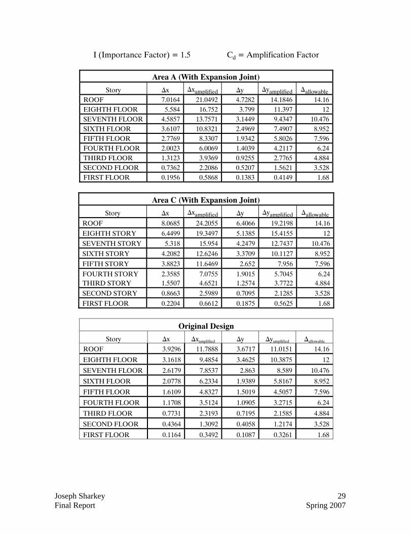
I (Importance Factor) = 1.5 Cd = Amplification Factor
Area A (With Expansion Joint)
Story ∆x ∆xamplified ∆y ∆yamplified ∆allowable
ROOF 7.0164 21.0492 4.7282 14.1846 14.16 EIGHTH FLOOR 5.584 16.752 3.799 11.397 12 SEVENTH FLOOR 4.5857 13.7571 3.1449 9.4347 10.476 SIXTH FLOOR 3.6107 10.8321 2.4969 7.4907 8.952 FIFTH FLOOR 2.7769 8.3307 1.9342 5.8026 7.596 FOURTH FLOOR 2.0023 6.0069 1.4039 4.2117 6.24 THIRD FLOOR 1.3123 3.9369 0.9255 2.7765 4.884 SECOND FLOOR 0.7362 2.2086 0.5207 1.5621 3.528 FIRST FLOOR 0.1956 0.5868 0.1383 0.4149 1.68
Area C (With Expansion Joint)
Story ∆x ∆xamplified ∆y ∆yamplified ∆allowable
ROOF 8.0685 24.2055 6.4066 19.2198 14.16 EIGHTH STORY 6.4499 19.3497 5.1385 15.4155 12 SEVENTH STORY 5.318 15.954 4.2479 12.7437 10.476 SIXTH STORY 4.2082 12.6246 3.3709 10.1127 8.952 FIFTH STORY 3.8823 11.6469 2.652 7.956 7.596 FOURTH STORY 2.3585 7.0755 1.9015 5.7045 6.24 THIRD STORY 1.5507 4.6521 1.2574 3.7722 4.884 SECOND STORY 0.8663 2.5989 0.7095 2.1285 3.528 FIRST FLOOR 0.2204 0.6612 0.1875 0.5625 1.68
Original Design
Story ∆x ∆xamplified ∆y ∆yamplified ∆allowable ROOF 3.9296 11.7888 3.6717 11.0151 14.16
EIGHTH FLOOR 3.1618 9.4854 3.4625 10.3875 12
SEVENTH FLOOR 2.6179 7.8537 2.863 8.589 10.476
SIXTH FLOOR 2.0778 6.2334 1.9389 5.8167 8.952
FIFTH FLOOR 1.6109 4.8327 1.5019 4.5057 7.596
FOURTH FLOOR 1.1708 3.5124 1.0905 3.2715 6.24
THIRD FLOOR 0.7731 2.3193 0.7195 2.1585 4.884
SECOND FLOOR 0.4364 1.3092 0.4058 1.2174 3.528
FIRST FLOOR 0.1164 0.3492 0.1087 0.3261 1.68
Joseph Sharkey 30 Final Report Spring 2007
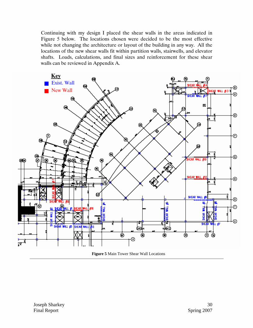
Figure 5 Main Tower Shear Wall Locations
Continuing with my design I placed the shear walls in the areas indicated in Figure 5 below. The locations chosen were decided to be the most effective while not changing the architecture or layout of the building in any way. All the locations of the new shear walls fit within partition walls, stairwells, and elevator shafts. Loads, calculations, and final sizes and reinforcement for these shear walls can be reviewed in Appendix A.
Exist. Wall New Wall
Key
Joseph Sharkey 31 Final Report Spring 2007
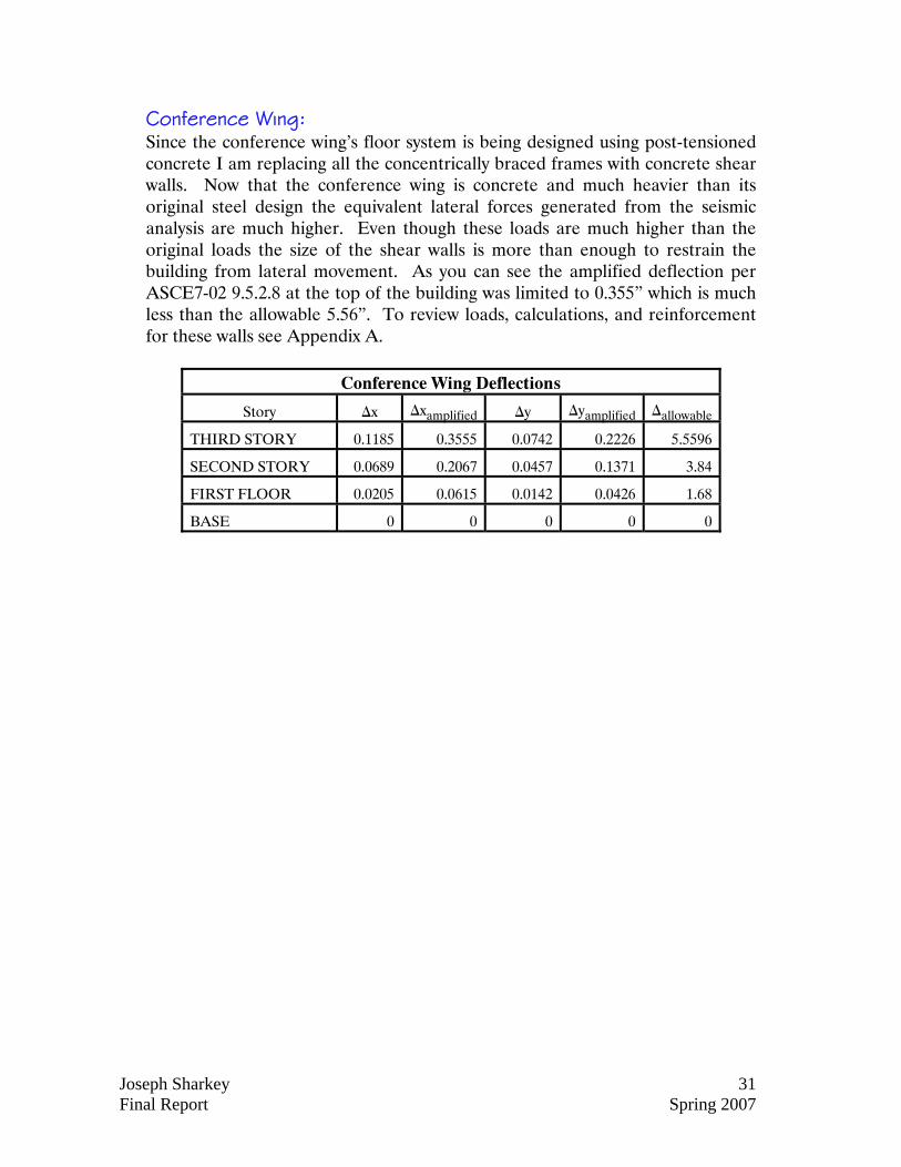
Conference Wing: Since the conference wing’s floor system is being designed using post-tensioned concrete I am replacing all the concentrically braced frames with concrete shear walls. Now that the conference wing is concrete and much heavier than its original steel design the equivalent lateral forces generated from the seismic analysis are much higher. Even though these loads are much higher than the original loads the size of the shear walls is more than enough to restrain the building from lateral movement. As you can see the amplified deflection per ASCE7-02 9.5.2.8 at the top of the building was limited to 0.355” which is much less than the allowable 5.56”. To review loads, calculations, and reinforcement for these walls see Appendix A.
Conference Wing Deflections
Story ∆x ∆xamplified ∆y ∆yamplified ∆allowable
THIRD STORY 0.1185 0.3555 0.0742 0.2226 5.5596
SECOND STORY 0.0689 0.2067 0.0457 0.1371 3.84
FIRST FLOOR 0.0205 0.0615 0.0142 0.0426 1.68
BASE 0 0 0 0 0
Joseph Sharkey 32 Final Report Spring 2007
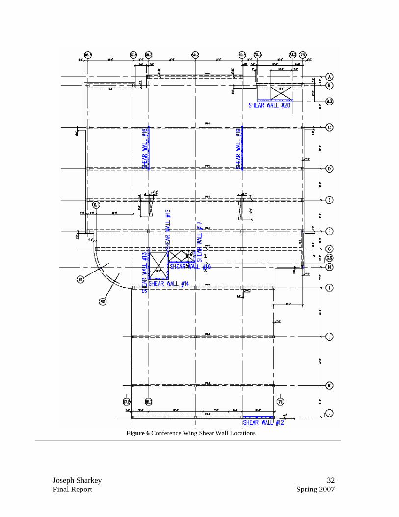
Figure 6 Conference Wing Shear Wall Locations
Joseph Sharkey 33 Final Report Spring 2007
5”
1¼”
1¼”
1¼”
Exterior Span Interior Spans
10”
1¼”
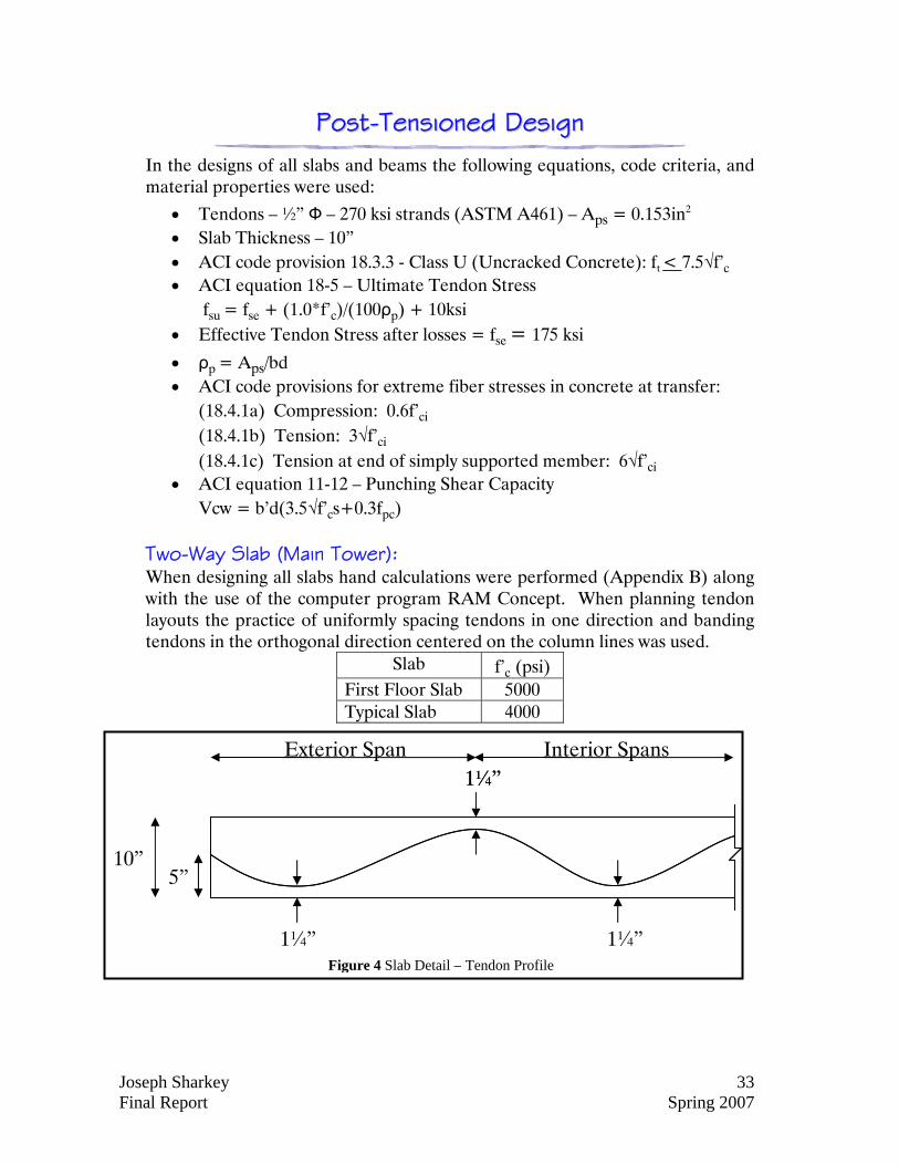
Figure 4 Slab Detail – Tendon Profile
PPoosstt--TTeennssiioonneedd DDeessiiggnn
In the designs of all slabs and beams the following equations, code criteria, and material properties were used:
• Tendons – ½” Ф – 270 ksi strands (ASTM A461) – Aps = 0.153in2 • Slab Thickness – 10” • ACI code provision 18.3.3 - Class U (Uncracked Concrete): ft < 7.5√f’c • ACI equation 18-5 – Ultimate Tendon Stress
fsu = fse + (1.0*f’c)/(100ρp) + 10ksi • Effective Tendon Stress after losses = fse = 175 ksi
• ρp = Aps/bd • ACI code provisions for extreme fiber stresses in concrete at transfer:
(18.4.1a) Compression: 0.6f’ci (18.4.1b) Tension: 3√f’ci
(18.4.1c) Tension at end of simply supported member: 6√f’ci • ACI equation 11-12 – Punching Shear Capacity
Vcw = b’d(3.5√f’cs+0.3fpc)
Two-Way Slab (Main Tower): When designing all slabs hand calculations were performed (Appendix B) along with the use of the computer program RAM Concept. When planning tendon layouts the practice of uniformly spacing tendons in one direction and banding tendons in the orthogonal direction centered on the column lines was used.
Slab f’c (psi) First Floor Slab 5000 Typical Slab 4000
Joseph Sharkey 34 Final Report Spring 2007
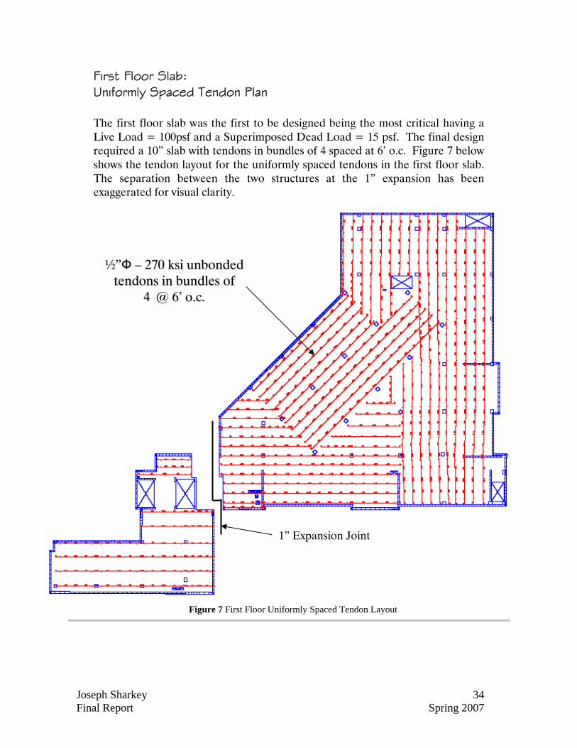
Figure 7 First Floor Uniformly Spaced Tendon Layout
First Floor Slab: Uniformly Spaced Tendon Plan The first floor slab was the first to be designed being the most critical having a Live Load = 100psf and a Superimposed Dead Load = 15 psf. The final design required a 10” slab with tendons in bundles of 4 spaced at 6’ o.c. Figure 7 below shows the tendon layout for the uniformly spaced tendons in the first floor slab. The separation between the two structures at the 1” expansion has been exaggerated for visual clarity.
1” Expansion Joint
½½””ФФ –– 227700 kkssii uunnbboonnddeedd tteennddoonnss iinn bbuunnddlleess ooff
44 @@ 66’’ oo..cc..
Joseph Sharkey 35 Final Report Spring 2007
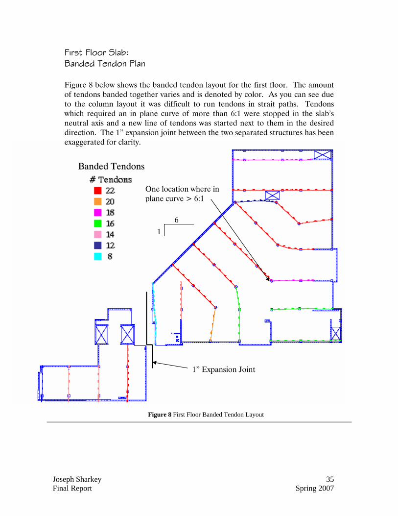
Figure 8 First Floor Banded Tendon Layout
First Floor Slab: Banded Tendon Plan Figure 8 below shows the banded tendon layout for the first floor. The amount of tendons banded together varies and is denoted by color. As you can see due to the column layout it was difficult to run tendons in strait paths. Tendons which required an in plane curve of more than 6:1 were stopped in the slab’s neutral axis and a new line of tendons was started next to them in the desired direction. The 1” expansion joint between the two separated structures has been exaggerated for clarity.
BBaannddeedd TTeennddoonnss
1” Expansion Joint
One location where in plane curve > 6:1
6 1
Joseph Sharkey 36 Final Report Spring 2007
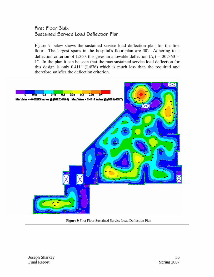
Figure 9 First Floor Sustained Service Load Deflection Plan
First Floor Slab: Sustained Service Load Deflection Plan Figure 9 below shows the sustained service load deflection plan for the first floor. The largest spans in the hospital’s floor plan are 30’. Adhering to a deflection criterion of L/360, this gives an allowable deflection (∆a) = 30’/360 = 1”. In the plan it can be seen that the max sustained service load deflection for this design is only 0.411” (L/876) which is much less than the required and therefore satisfies the deflection criterion.
Joseph Sharkey 37 Final Report Spring 2007
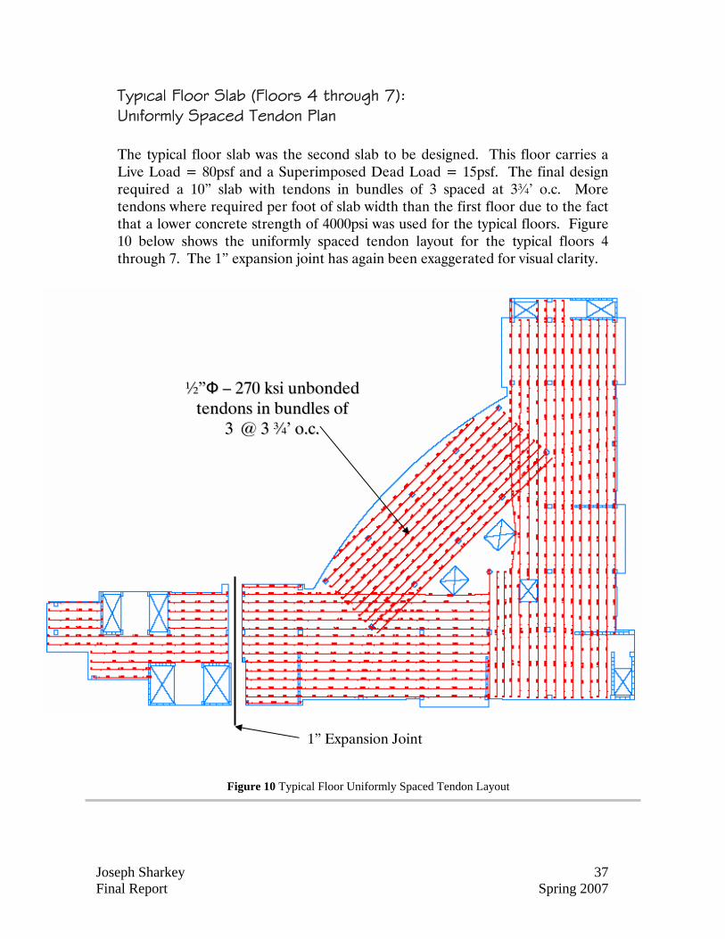
Figure 10 Typical Floor Uniformly Spaced Tendon Layout
Typical Floor Slab (Floors 4 through 7): Uniformly Spaced Tendon Plan The typical floor slab was the second slab to be designed. This floor carries a Live Load = 80psf and a Superimposed Dead Load = 15psf. The final design required a 10” slab with tendons in bundles of 3 spaced at 3¾’ o.c. More tendons where required per foot of slab width than the first floor due to the fact that a lower concrete strength of 4000psi was used for the typical floors. Figure 10 below shows the uniformly spaced tendon layout for the typical floors 4 through 7. The 1” expansion joint has again been exaggerated for visual clarity.
1” Expansion Joint
½½””ФФ –– 227700 kkssii uunnbboonnddeedd tteennddoonnss iinn bbuunnddlleess ooff
33 @@ 33 ¾¾’’ oo..cc..
Joseph Sharkey 38 Final Report Spring 2007
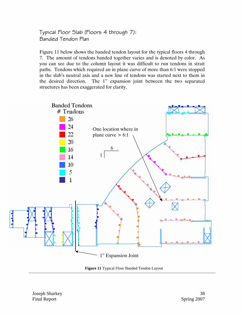
Figure 11 Typical Floor Banded Tendon Layout
Typical Floor Slab (Floors 4 through 7): Banded Tendon Plan Figure 11 below shows the banded tendon layout for the typical floors 4 through 7. The amount of tendons banded together varies and is denoted by color. As you can see due to the column layout it was difficult to run tendons in strait paths. Tendons which required an in plane curve of more than 6:1 were stopped in the slab’s neutral axis and a new line of tendons was started next to them in the desired direction. The 1” expansion joint between the two separated structures has been exaggerated for clarity.
1” Expansion Joint
BBaannddeedd TTeennddoonnss
One location where in plane curve > 6:1
6 1
Joseph Sharkey 39 Final Report Spring 2007
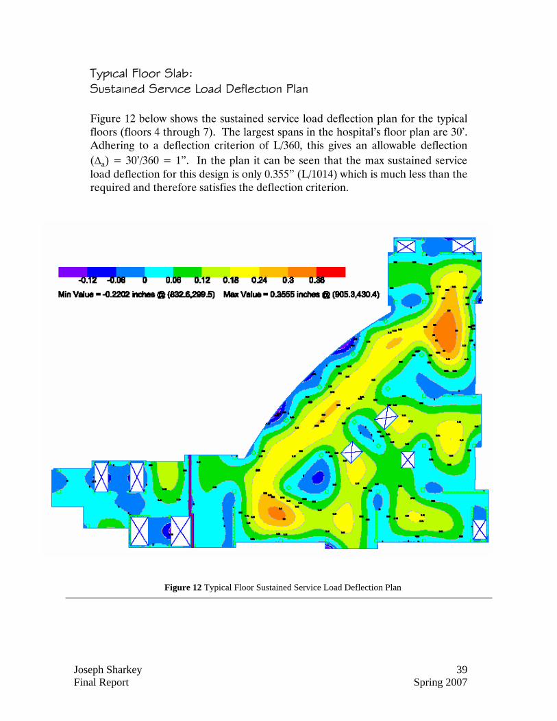
Figure 12 Typical Floor Sustained Service Load Deflection Plan
Typical Floor Slab: Sustained Service Load Deflection Plan Figure 12 below shows the sustained service load deflection plan for the typical floors (floors 4 through 7). The largest spans in the hospital’s floor plan are 30’. Adhering to a deflection criterion of L/360, this gives an allowable deflection (∆a) = 30’/360 = 1”. In the plan it can be seen that the max sustained service load deflection for this design is only 0.355” (L/1014) which is much less than the required and therefore satisfies the deflection criterion.
Joseph Sharkey 40 Final Report Spring 2007
5”
1¼”
1¼”
1¼”
Exterior Span Interior Spans
10”
1¼”
Figure 14 Slab Detail – Tendon Profile
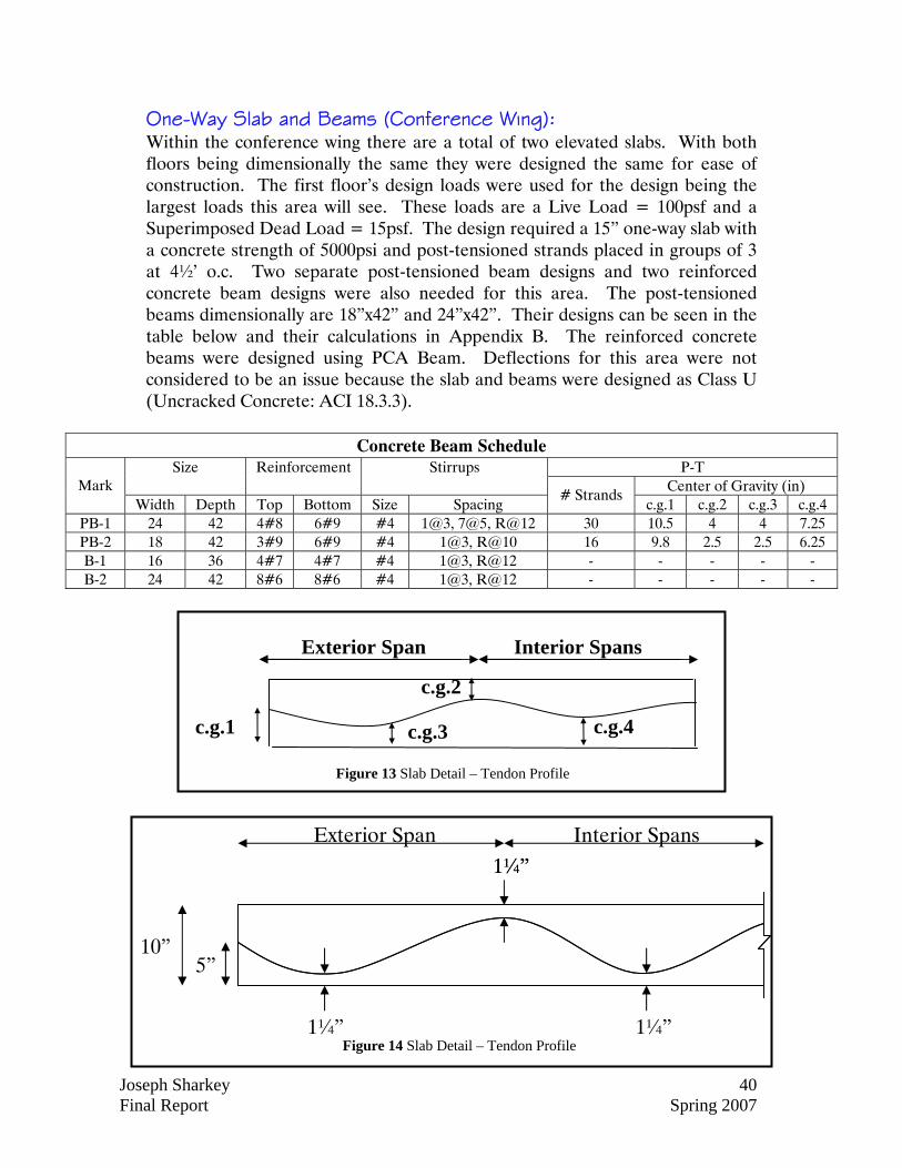
One-Way Slab and Beams (Conference Wing): Within the conference wing there are a total of two elevated slabs. With both floors being dimensionally the same they were designed the same for ease of construction. The first floor’s design loads were used for the design being the largest loads this area will see. These loads are a Live Load = 100psf and a Superimposed Dead Load = 15psf. The design required a 15” one-way slab with a concrete strength of 5000psi and post-tensioned strands placed in groups of 3 at 4½’ o.c. Two separate post-tensioned beam designs and two reinforced concrete beam designs were also needed for this area. The post-tensioned beams dimensionally are 18”x42” and 24”x42”. Their designs can be seen in the table below and their calculations in Appendix B. The reinforced concrete beams were designed using PCA Beam. Deflections for this area were not considered to be an issue because the slab and beams were designed as Class U (Uncracked Concrete: ACI 18.3.3).
Concrete Beam Schedule P-T Size Reinforcement Stirrups
Center of Gravity (in) Mark Width Depth Top Bottom Size Spacing
# Strands c.g.1 c.g.2 c.g.3 c.g.4
PB-1 24 42 4#8 6#9 #4 1@3, 7@5, R@12 30 10.5 4 4 7.25 PB-2 18 42 3#9 6#9 #4 1@3, R@10 16 9.8 2.5 2.5 6.25 B-1 16 36 4#7 4#7 #4 1@3, R@12 - - - - - B-2 24 42 8#6 8#6 #4 1@3, R@12 - - - - -
c.g.1
c.g.2
c.g.3 c.g.4
Exterior Span Interior Spans
Figure 13 Slab Detail – Tendon Profile
Joseph Sharkey 41 Final Report Spring 2007
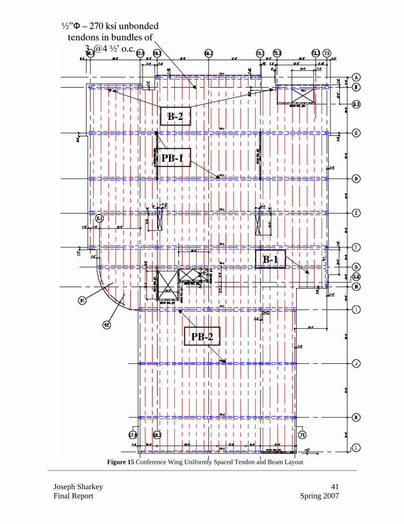
Figure 15 Conference Wing Uniformly Spaced Tendon and Beam Layout
B-2
B-1
PB-1
PB-2
½½””ФФ –– 227700 kkssii uunnbboonnddeedd tteennddoonnss iinn bbuunnddlleess ooff
33 @@44 ½½’’ oo..cc..
Joseph Sharkey 42 Final Report Spring 2007
CCoolluummnn DDeessiiggnn
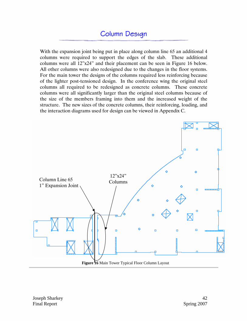
With the expansion joint being put in place along column line 65 an additional 4 columns were required to support the edges of the slab. These additional columns were all 12”x24” and their placement can be seen in Figure 16 below. All other columns were also redesigned due to the changes in the floor systems. For the main tower the designs of the columns required less reinforcing because of the lighter post-tensioned design. In the conference wing the original steel columns all required to be redesigned as concrete columns. These concrete columns were all significantly larger than the original steel columns because of the size of the members framing into them and the increased weight of the structure. The new sizes of the concrete columns, their reinforcing, loading, and the interaction diagrams used for design can be viewed in Appendix C.
Figure 16 Main Tower Typical Floor Column Layout
Column Line 65 1” Expansion Joint
12”x24” Columns
Joseph Sharkey 43 Final Report Spring 2007
IImmppaacctt oonn FFoouunnddaattiioonnss
The foundations of the Christiana Hospital as mentioned earlier are currently a mat foundation under the main tower and spread footings under the conference wing. With the new post-tensioned design the building weight was reduced which in turn imposed a lighter load on the foundations. After reanalyzing the foundations not many large changes can be made because the soils low bearing pressure (4000psf). The reason there is a mat foundation is because the spread footings required to support the main tower would be so large they would have to overlap. Due to this a mat foundation was chosen. Even though the building is now lighter, the loads on each column have not been reduced enough to allow spread footings to be used and therefore a mat foundation must also be used under the main tower in my design. In the case of the conference wing there is some change in footing sizes. For my concrete design all the footings were required to be sized larger while some were forced to be made into combined footings. All of these changes have been taken into account in my schedule and cost estimate.
Joseph Sharkey 44 Final Report Spring 2007
CCoonnssttrruuccttiioonn MMaannaaggeemmeenntt BBrreeaaddtthh
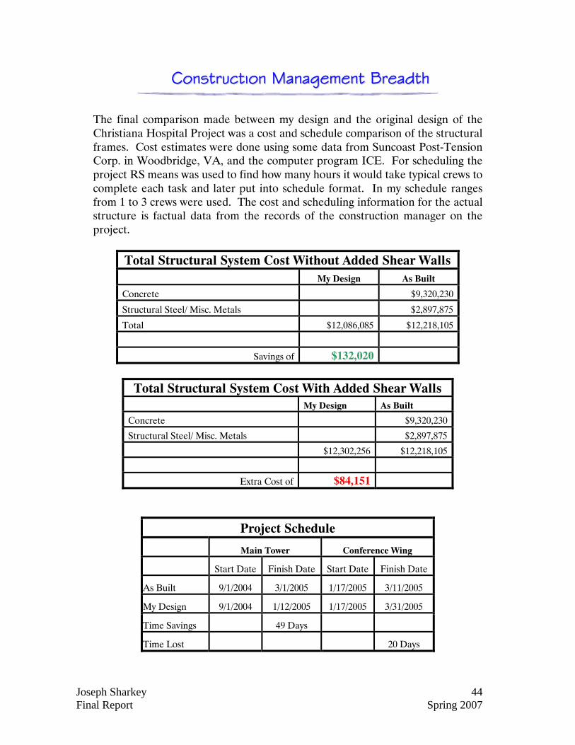
The final comparison made between my design and the original design of the Christiana Hospital Project was a cost and schedule comparison of the structural frames. Cost estimates were done using some data from Suncoast Post-Tension Corp. in Woodbridge, VA, and the computer program ICE. For scheduling the project RS means was used to find how many hours it would take typical crews to complete each task and later put into schedule format. In my schedule ranges from 1 to 3 crews were used. The cost and scheduling information for the actual structure is factual data from the records of the construction manager on the project.
Total Structural System Cost Without Added Shear Walls My Design As Built
Concrete $9,320,230
Structural Steel/ Misc. Metals $2,897,875
Total $12,086,085 $12,218,105
Savings of $132,020
Total Structural System Cost With Added Shear Walls My Design As Built
Concrete $9,320,230
Structural Steel/ Misc. Metals $2,897,875
$12,302,256 $12,218,105
Extra Cost of $84,151
Project Schedule
Main Tower Conference Wing
Start Date Finish Date Start Date Finish Date
As Built 9/1/2004 3/1/2005 1/17/2005 3/11/2005
My Design 9/1/2004 1/12/2005 1/17/2005 3/31/2005
Time Savings 49 Days
Time Lost 20 Days
Joseph Sharkey 45 Final Report Spring 2007
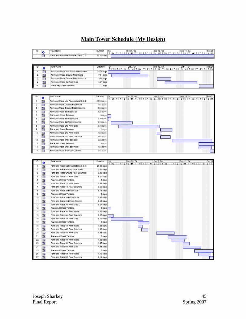
Main Tower Schedule (My Design)
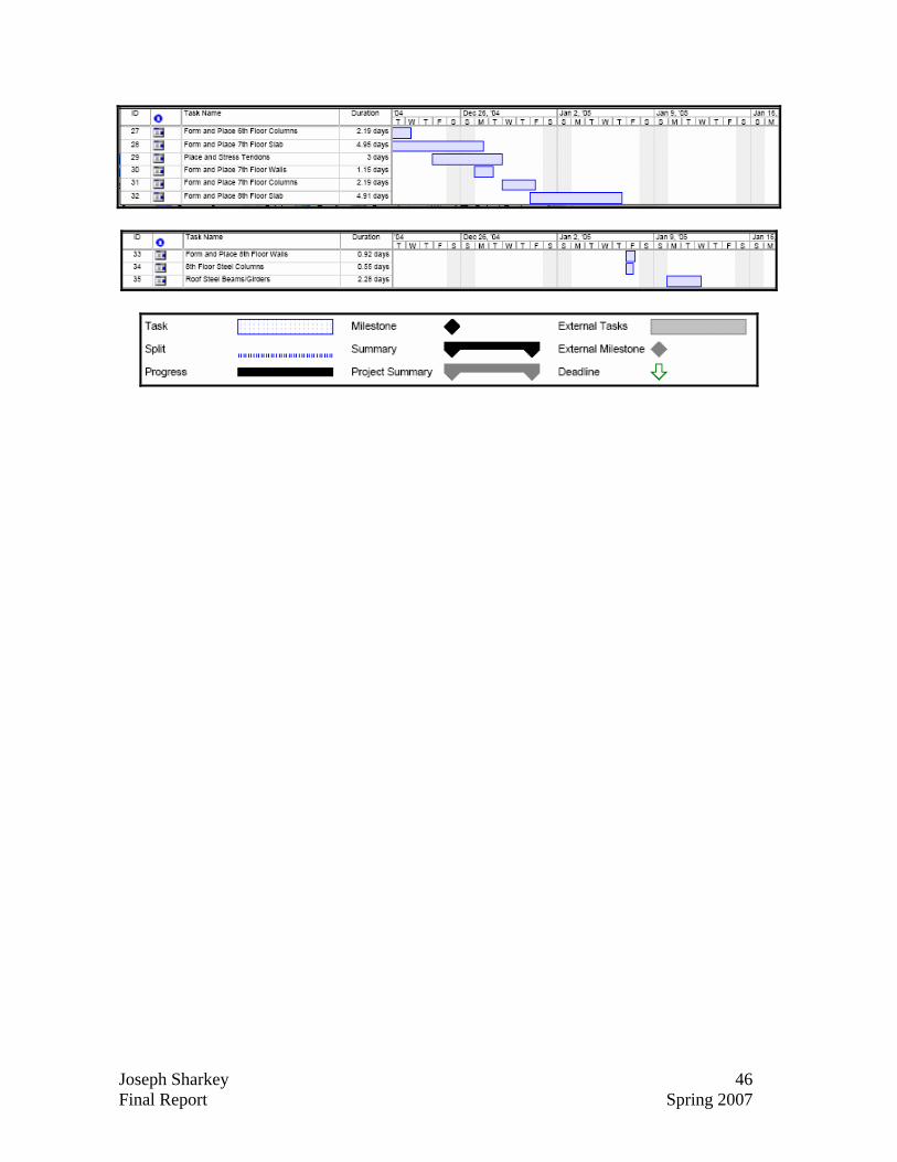
Joseph Sharkey 46 Final Report Spring 2007
Joseph Sharkey 47 Final Report Spring 2007
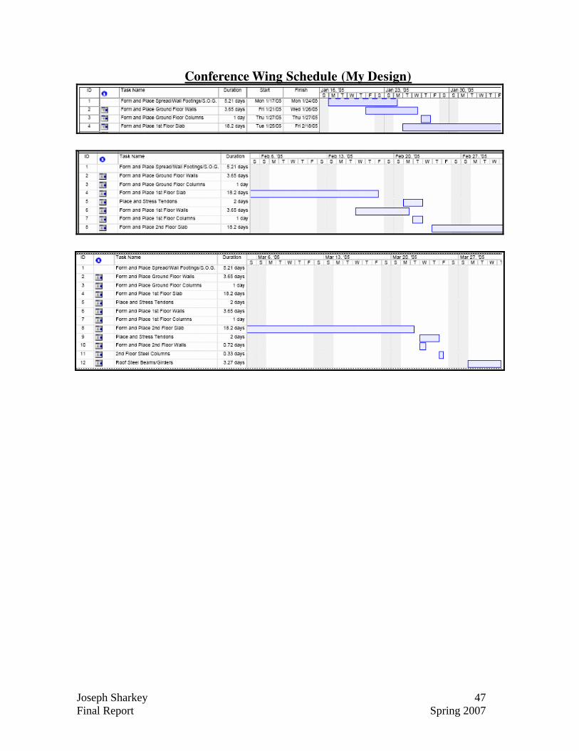
Conference Wing Schedule (My Design)
Joseph Sharkey 48 Final Report Spring 2007
AAccoouussttiiccss BBrreeaaddtthh
The main attraction to the conference wing in this project is a large conference room on the first floor. Being that this type of room will be mainly used for lectures, conferences, etc. it is essential for the room to be correctly designed acoustically so that information transmitted by way of sound can reach the listener most effectively. Currently the room has been designed using ½” thick acousticotton panels, wood panels, and 5/8” gypsum along the walls, high traffic carpet and heavily upholstered seats on the floor, and 4’x4’ Armstrong Optima acoustical ceiling tiles on the ceiling. Upon initial inspection this amount of sound absorptive materials seemed to be too high which in turn would deliver a much shorter than desirable reverberation time (the time it takes in seconds for average sound in a room to decrease by 60 decibels). In this type of space the optimum reverberation time is between 0.7 and 1.1 seconds. As predicted earlier the amount of absorptive material in this space is too high giving reverberation times as short as 0.31 seconds at 4000 Hz and only as long as 0.53 seconds at 500 Hz. With this low of a reverberation time sound dies too quickly making it difficult to understand speech. With further investigation I found that a much more desirable reverberation time could be achieved by using much less absorptive materials which also would greatly reduce the cost of the room. By removing 90% of the acousticotton paneling and all of the Armstrong ceiling tiles and replacing them with 5/8” gypsum the reverberation time was increased to 0.66 seconds at 4000Hz and 1.14 seconds at 500 Hz. With cost information found from local distributors the price of this room alone was reduced by $12,591. The only downfall to this design is that by removing all the ceiling tiles and replacing them with gypsum the room’s versatility is taken away. Being a conference room, new wiring will most likely need to be run with changes in technology and removable ceiling tiles lend themselves to this need much better than gypsum. The second item I looked at was transmission loss. Because this room is located next to a corridor it requires a Sound Transmission Coefficient (STC) of 40. The walls in the current design of the building call for a 3½” sound attenuation blanket which gives an STC of 49 bringing the wall up and over an STC of 42 that allows the wall to be considered quiet for this spatial relationship. Calculations, material properties, and cost comparisons can be viewed in Appendix D.
Joseph Sharkey 49 Final Report Spring 2007
CCoonncclluussiioonnss
Sectioning Structure with Expansion Joint: The attempt made to reduce the loads in the shear walls by means of dividing the main tower into two separate structures showed to be a very uneconomical design. By separating the structure the eccentricity between the center of mass and the center of rigidity actual increased thus increasing the magnitude of load on each shear wall. The portion of the load on each wall caused by this torsional effect was so high that extra shear walls were required to be put in place adding extra time to the schedule and cost to the project making the as built design the best method of design in this area. Post Tension Design vs. Reinforced Concrete Main Tower: By designing the main tower’s floor systems as post-tensioned instead of a reinforced concrete slab with drop panels two things were capable of being achieved. First, the project schedule was capable of being decreased by 49 days and the cost was decreased by $132,020 or 1%. These benefits were mainly from the fact that the floor system was capable of being designed without drop panels which saves on labor costs, formwork, and schedule. While both of these outcomes are beneficial I feel they are not large enough of changes to make a post-tensioned design more practical. The reason for my conclusion is that in hospitals, penetrations in slabs are very common and post-tensioned slabs do not lend themselves well to this. Slab penetrations which are preplanned are not as problematic but those which require any sort of drilling after the slab has been placed can pose problems. These problems arise when tendons are hit and broken by drilling equipment which then requires a very pricey fix.
Post Tension Design vs. Steel Design Conference Wing: The design of the conference wing as a post-tensioned slab and beam system with concrete columns and shear walls also showed to be not as practical as the original steel design. Due to the added dead load of the structure both columns and floor thicknesses needed to be increased. Along with the added mass of the structure it also added an extra 20 days to the projects schedule which is a 37% increase to the steel design schedule.
Joseph Sharkey 50 Final Report Spring 2007
Acoustic Design: In my acoustical analysis of the major conference room in the conference wing of the Christiana Hospital Project it was found that the amount of sound absorptive materials used to line both the walls and ceiling was too high and lead to the room having a much shorter reverberation time than the desired range of 0.7-1.1 seconds. My design, which decreased the amount of acousticotton used and completely deleted the use of acoustical ceiling tiles, allowed the room to have a longer reverberation time which fell within the desired range of 0.7-1.1 seconds. Along with achieving the desired reverberation time it also allowed the room to be designed for a much lower price.
AAcckknnoowwlleeddggeemmeennttss
•• CCaagglleeyy && AAssssoocciiaatteess FFrraannkk MMaalliittss JJooee AAjjeelllloo JJaammeess LLaakkeeyy
•• WWiillmmoott SSaannzz SShheeiillaa WWiilllliiaammss
•• SSuunnccooaasstt PPoosstt--TTeennssiioonn •• AAccoouussttiiccaall PPaanneell RReessoouurrcceess •• AArrmmssttrroonngg •• MMaarrjjaamm SSuuppppllyy •• AAEE FFaaccuullttyy
DDrr.. AAllii MMeemmaarrii DDrr.. AAnnddrreess LLeeppaaggee PPrrooffeessssoorr KKeevviinn PPaarrffiitttt