Embed Size (px)
Citation preview
Choke Design Using Iron Powder Toroidal Cores
Presented by:
Gurveer Singh(Student, EE136 – Power Electronics)
Introduction – Choke Design UsingIron Powder Toroidal Cores
Iron powder toroids can be very suitable for chokes in output filters of power converters.
The term “choke” is used to describe an inductor which carries A large DC bias current. Small ac ripple current.
Design Approach
Graphical design method based on the nomogram is emphasized.
Nomogram is a plot or graphical representation of parameter relations obtained from equations.
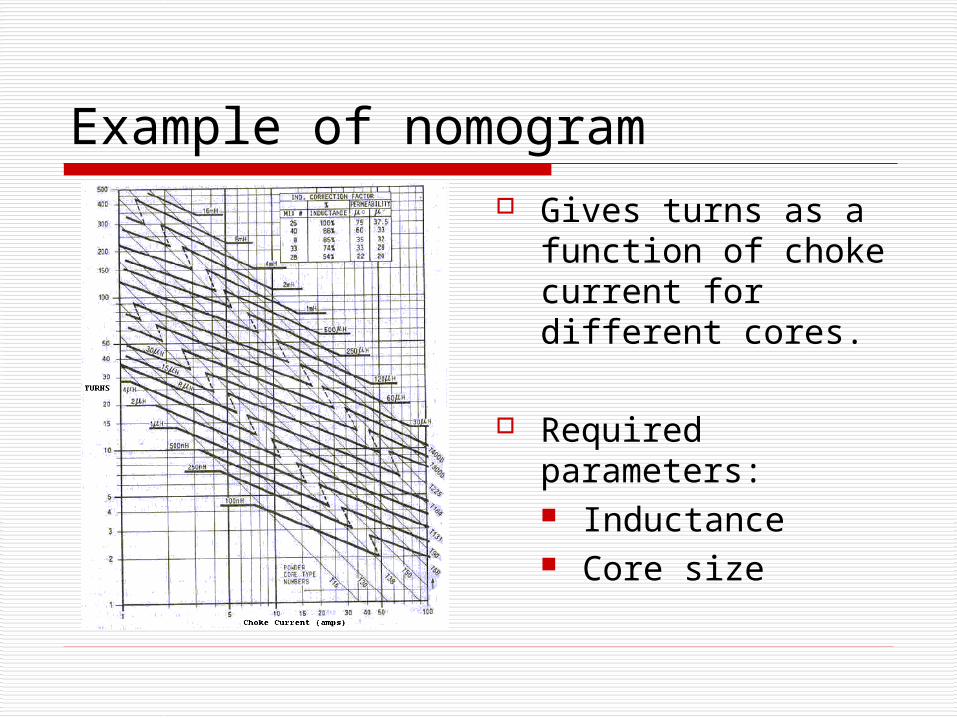
Example of nomogram Gives turns as a
function of choke current for different cores.
Required parameters: Inductance Core size
Design Example
Step1: Calculate the inductance required at full load.
Step2: Obtain Core Size TurnsFrom nomogram
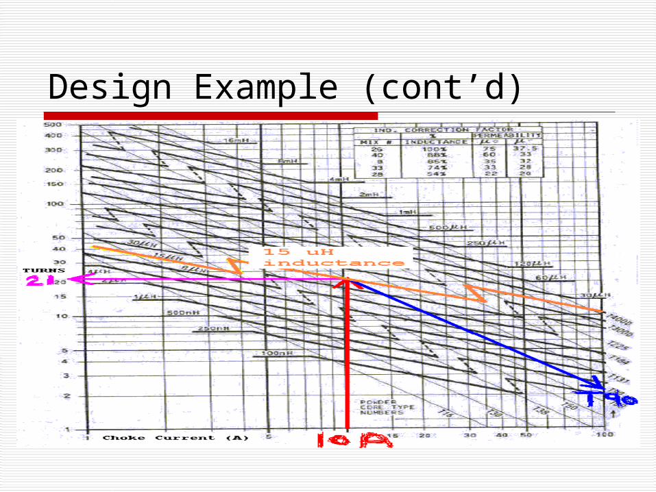
Design Example (cont’d) Enter the nomogram at the bottom scale.
With the required maximum load current of 10A.
Project upward to the required inductance, 14.8uH. (use heavy line marked 15uH).
Nearest diagonal (thin line) gives the required core size (T90 in this case).
Horizontal left projection from the core and inductance intersect indicates the required turns (21 in this example).
Design Example (cont’d)
Select toroidal choke winding depending on the required performance Option A: Minimum Loss Winding
(Full Winding) Lowest copper loss, difficult and
expensive to manufacture. Option B: Single-Layer Winding
Higher copper loss, higher temperature rise, simple to manufacture.
Option C: Winding for a Specified Temperature Rise More difficult to design.
Design Example (cont’d) – Using Option A
Already selected: Inductance, turns, and core size.
Now select wire size using another nomogram: Use a nomogram showing the gauge of wire and
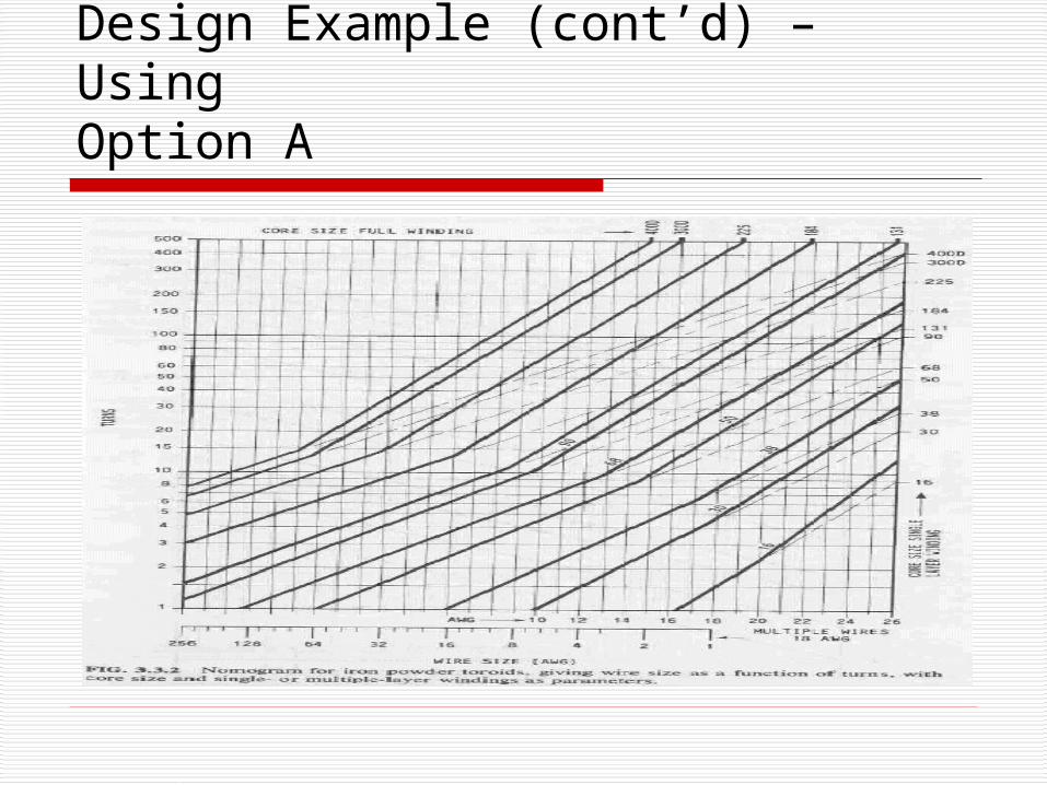
number of turns. Enter the graph from the left with the required
number of turns (21). The intersection of the number of turns with the solid diagonal “core line” for the selected core indicates the required wire gauge on the lower scale (#13 AWG).
If intersect is above slope discontinuity: Multiple-layer winding.
Design Example (cont’d) – Using Option A
Design Example (cont’d) – Using Option A
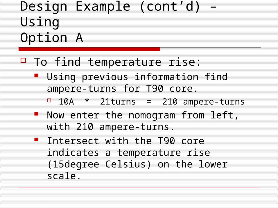
To find temperature rise: Using previous information find ampere-
turns for T90 core. 10A * 21turns = 210 ampere-turns
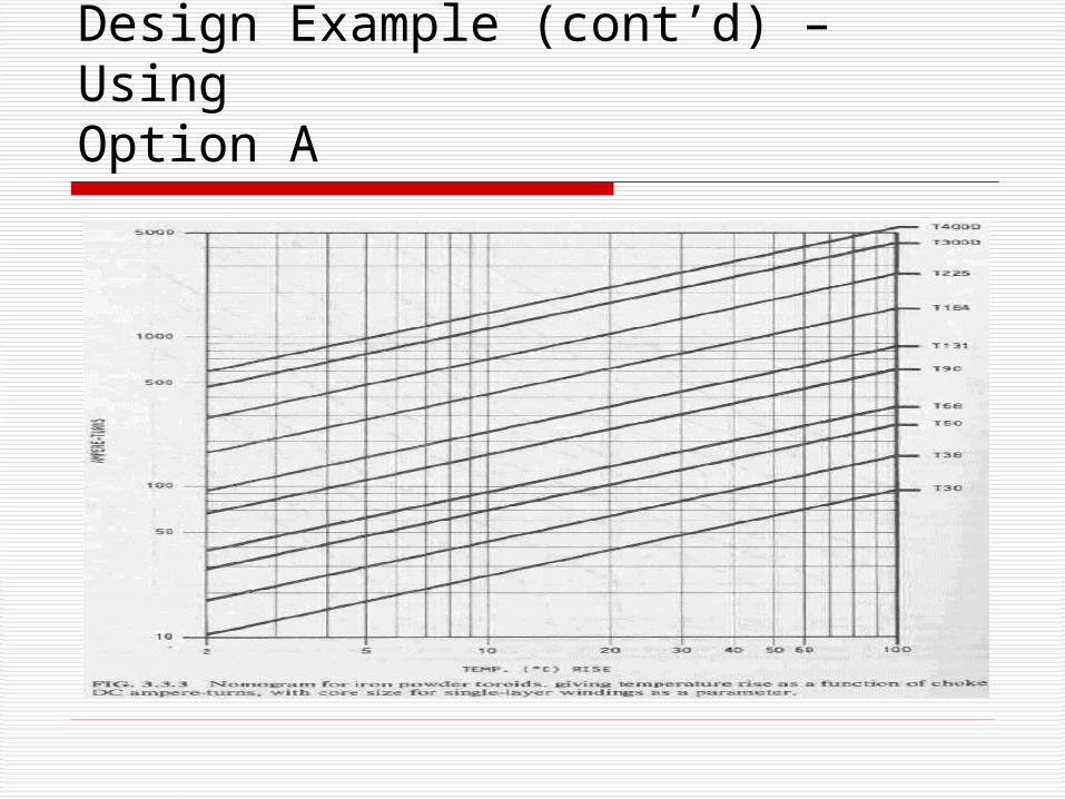
Now enter the nomogram from left, with 210 ampere-turns.
Intersect with the T90 core indicates a temperature rise (15degree Celsius) on the lower scale.
Design Example (cont’d) – Using Option A
Design Example (cont’d) – Using Option A
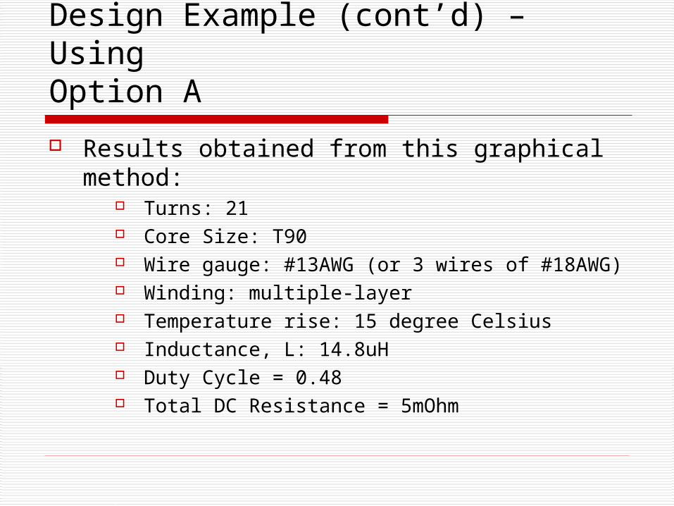
Results obtained from this graphical method:
Turns: 21 Core Size: T90 Wire gauge: #13AWG (or 3 wires of #18AWG) Winding: multiple-layer Temperature rise: 15 degree Celsius Inductance, L: 14.8uH Duty Cycle = 0.48 Total DC Resistance = 5mOhm
Design Example (cont’d) – Using Option A
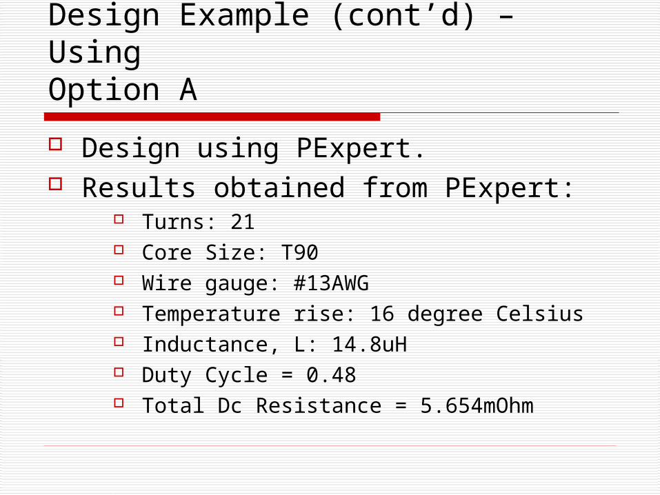
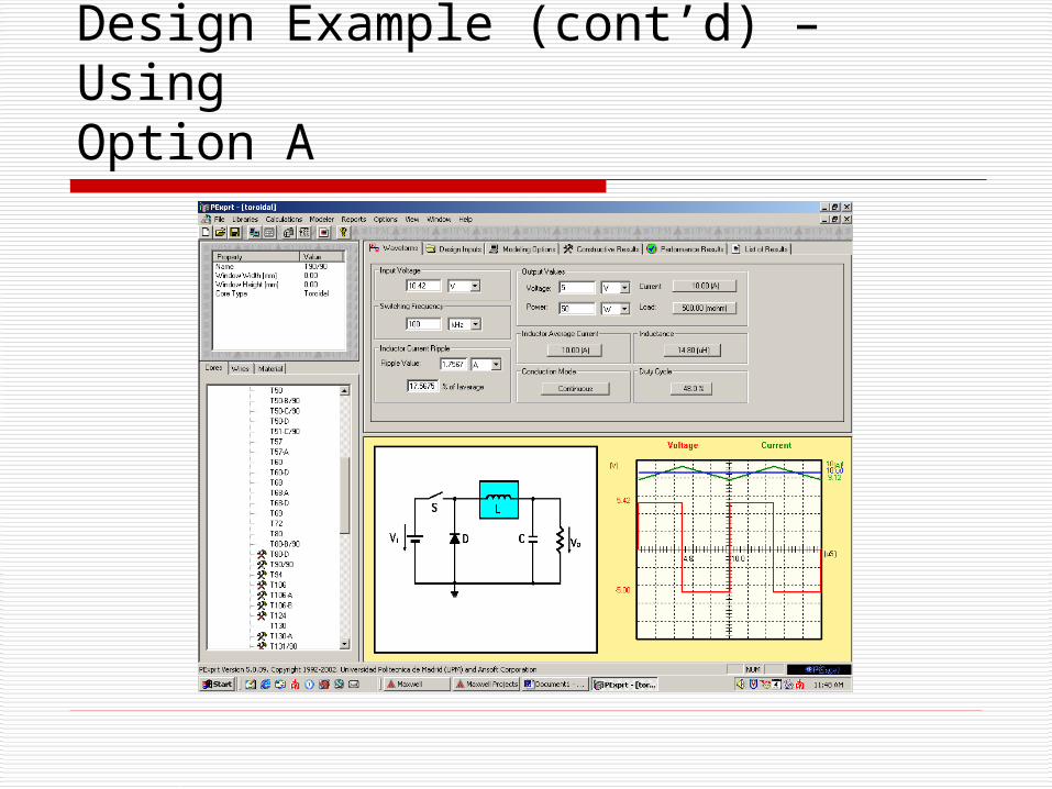
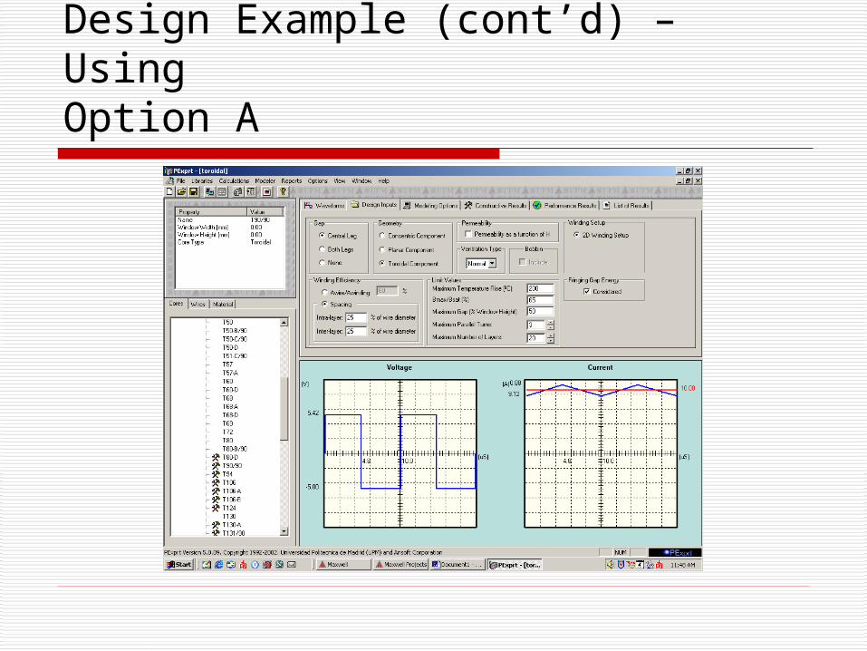
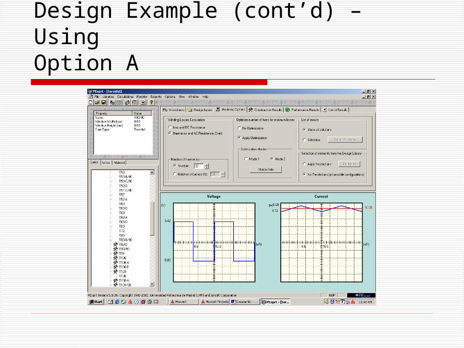
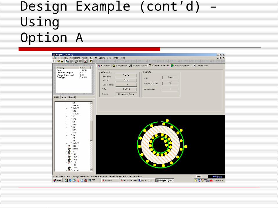
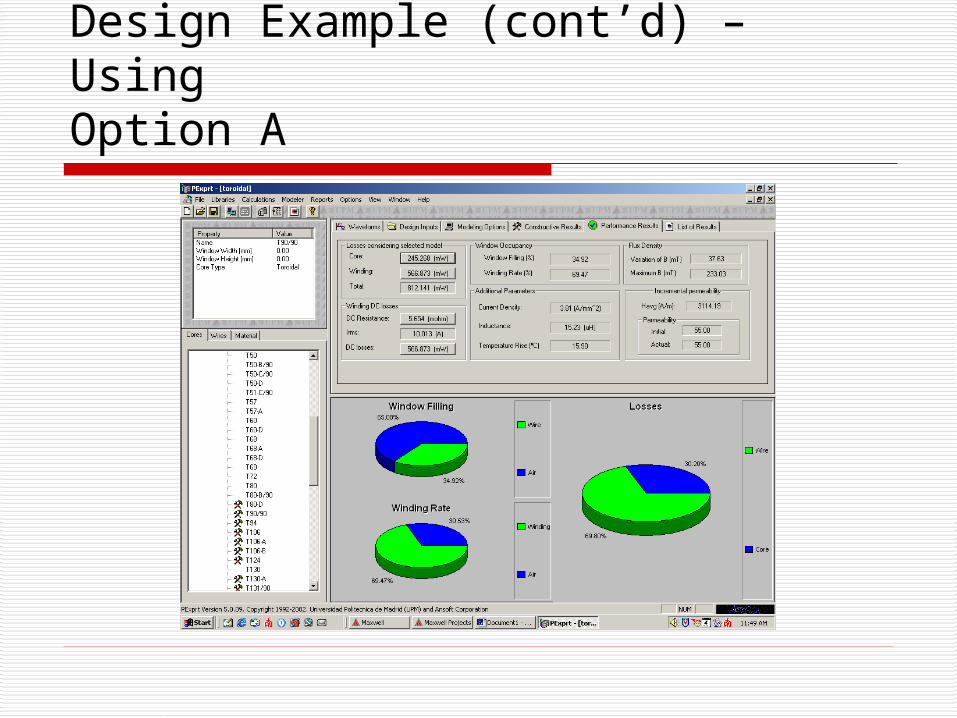
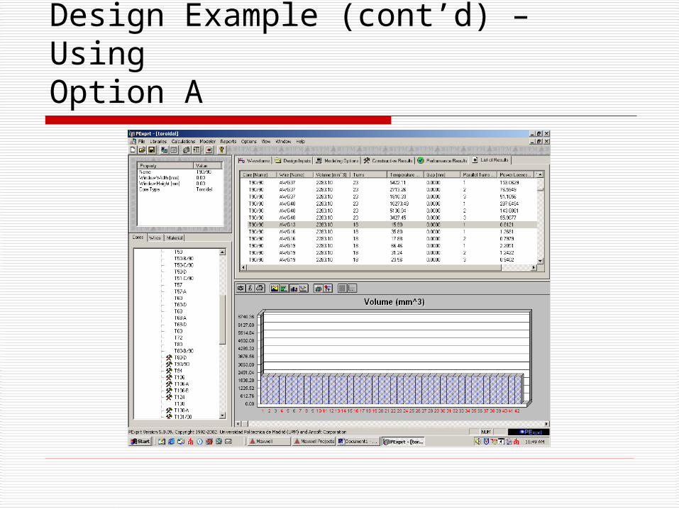
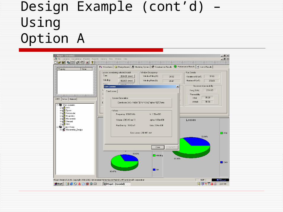
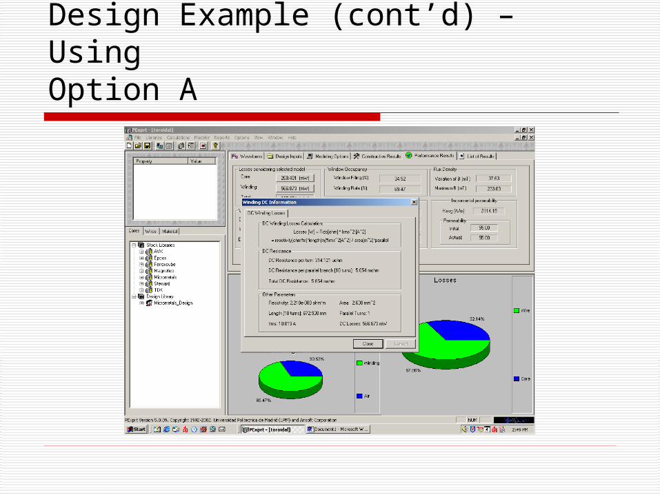
Design using PExpert. Results obtained from PExpert:
Turns: 21 Core Size: T90 Wire gauge: #13AWG Temperature rise: 16 degree Celsius Inductance, L: 14.8uH Duty Cycle = 0.48 Total Dc Resistance = 5.654mOhm
Design Example (cont’d) – Using Option A
Design Example (cont’d) – Using Option A
Design Example (cont’d) – Using Option A
Design Example (cont’d) – Using Option A
Design Example (cont’d) – Using Option A
Design Example (cont’d) – Using Option A
Design Example (cont’d) – Using Option A
Design Example (cont’d) – Using Option A

Design Example (cont’d) – Using Option A

Design Example (cont’d) – Using Option A
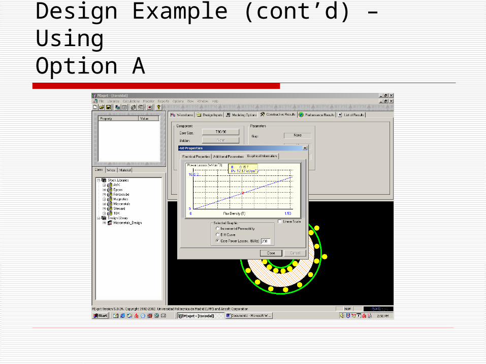
Design Example (cont’d) – Using Option A

Design Example (cont’d) – Using Option A
Conclusion Verified Results for design:
Nomogram (graphical method – the book approach) results with PExpert results.
Graphical method is a easy and quick approach to designing, but provides approximate values. On the other hand, PExpert provides accurate and exact values and several other design options. To conclude, both approaches yield correct results and either one could be used depending upon the required accuracy, available time-line, and application.