Embed Size (px)
Citation preview
Proceedings of ASME Turbo Expo 2010: Power for Land, Sea and AirGT2010
June 10-14, 2010, Glasgow, UK
GT2010-23135
CH*/OH* CHEMILUMINESCENCE RESPONSE OF AN ATMOSPHERIC PREMIXEDFLAME UNDER VARYING OPERATING CONDITIONS
Daniel Guyot,Felix Guethe, Bruno Schuermans
AlstomCH-5405 Baden
Switzerland
Arnaud Lacarelle,Christian Oliver PaschereitTechnische Universitat Berlin
Germany
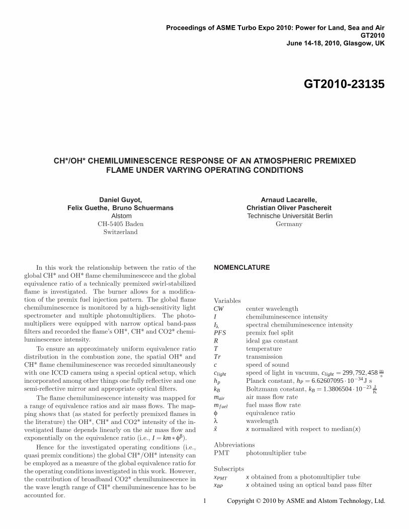
In this work the relationship between the ratio of theglobal CH* and OH* flame chemiluminescece and the globalequivalence ratio of a technically premixed swirl-stabilizedflame is investigated. The burner allows for a modifica-tion of the premix fuel injection pattern. The global flamechemiluminescence is monitored by a high-sensitivity lightspectrometer and multiple photomultipliers. The photo-multipliers were equipped with narrow optical band-passfilters and recorded the flame’s OH*, CH* and CO2* chemi-luminescence intensity.
To ensure an approximately uniform equivalence ratiodistribution in the combustion zone, the spatial OH* andCH* flame chemiluminescence was recorded simultaneouslywith one ICCD camera using a special optical setup, whichincorporated among other things one fully reflective and onesemi-reflective mirror and appropriate optical filters.
The flame chemiluminescence intensity was mapped fora range of equivalence ratios and air mass flows. The map-ping shows that (as stated for perfectly premixed flames inthe literature) the OH*, CH* and CO2* intensity of the in-vestigated flame depends linearly on the air mass flow andexponentially on the equivalence ratio (i.e., I = km∗φβ).
Hence for the investigated operating conditions (i.e.,quasi premix conditions) the global CH*/OH* intensity canbe employed as a measure of the global equivalence ratio forthe operating conditions investigated in this work. However,the contribution of broadband CO2* chemiluminescence inthe wave length range of CH* chemiluminescence has to beaccounted for.
NOMENCLATURE
VariablesCW center wavelengthI chemiluminescence intensityIλ spectral chemiluminescence intensityPFS premix fuel splitR ideal gas constantT temperatureTr transmissionc speed of soundclight speed of light in vacuum, clight = 299,792,458 m
shp Planck constant, hP = 6.62607095 ·10−34J skB Boltzmann constant, kB = 1.3806504 ·10−23 J
Kmair air mass flow ratemf uel fuel mass flow rateφ equivalence ratioλ wavelengthx x normalized with respect to median(x)
AbbreviationsPMT photomultiplier tube
SubscriptsxPMT x obtained from a photomultiplier tubexBP x obtained using an optical band pass filter
1
Proceedings of ASME Turbo Expo 2010: Power for Land, Sea and Air GT2010
June 14-18, 2010, Glasgow, UK
GT2010-23135
1 Copyright © 2010 by ASME and Alstom Technology, Ltd.

INTRODUCTIONThe observation of flame chemiluminescence is a widely
used technique in combustion diagnostics [1,2,3,4]. In par-ticular, the intensity of OH* or CH* chemiluminescence isoften used as a measure for the heat release in the flame.Detailed investigations of perfectly premixed flames haveshown that OH∗ or CH∗ chemiluminescence intensity de-pends linearly on the air/fuel mixture mass flow rate m andexponentially on the equivalence ratio phi of the flame inthe case of a globally uniform equivalence ratio distribution,i.e.
I = km∗φβ, (1)
where k and β are constants for one chemical species. Con-sequently, the ratio of both intensity signals (i.e. CH∗/OH∗)is a function of the equivalence ratio only. After calibrationmeasurements, the CH*/OH* ratio provides a measure ofthe equivalence ratio [1].
In most applications the flame’s global light emission iscaptured using one or multiple photomultipliers and fiberoptic cables. From these signals the global heat release orequivalence ratio is then estimated. In the case of hot spotsin the combustion zone due to e.g. non-uniform fuel dis-tribution and recirculation zones etc., the photomultipliersignal might not represent the global properties.
The relationship between the global CH*/OH* inten-sity ratio and the global equivalence ratio of a steady statetechnically premixed flame in a swirl-stabilized burner is in-vestigated. The global flame chemiluminescence spectrumis measured and corrected for heat radiation of the combus-tor. The global OH* and CH* chemiluminescence intensi-ties are obtained from the spectrum taking into account thesuperposition of CH* and broadband CO2* chemilumines-cence.
A method is presented that uses the spectral flamechemiluminescence results to obtain the global CH*/OH*intensity ratio of the flame from three photomultiplier sig-nals, which measure the flame’s OH*, CO2* and superim-posed CH*+CO2* intensity, respectively. The flame chemi-luminescence intensity is mapped for a range of equivalenceratios and air mass flows. The mapping shows that (asstated for perfectly premixed flames in the literature [1, 2])the OH*, CH* and CO2* intensity of the investigated flamefollows Eqn. 1 (I = km ∗ φβ). The flame’s global CH*/OH*intensity is shown to depend exponentially on the equiva-lence ratio and to be independent of the air mass flow for theoperating conditions investigated in this work. Hence theglobal CH*/OH* intensity can be employed as a measureof the global equivalence ratio.
Although only steady flames were investigated in thiswork, the identified relationship between equivalence ratioand CH*/OH* intensity ratio should also be valid for un-steady flames, provided that a uniform spatial distributionof the equivalence ratio is maintained at all times. Thework presented here is a continuation of the work presentedin [5], where the flame transfer function of an industrialswirl-stabilized burner under full engine pressure was de-termined from global flame chemiluminescence recording.
EXPERIMENTAL SET-UPCombustion Facility
All combustion results presented in this paper were ob-tained using the combustion facility shown in Fig. 1. Onthe upstream side the combustion test facility features anair preheater through which the combustion air is fed into aduct. Inside this duct sits the burner lance, through whichfuel (natural gas in this work) is supplied to the burner. Theatmospheric combustor has a 300mm long air-cooled quartzglass combustion chamber allowing for optical access to theflame. A water-cooled resonance tube of 1350mm in lengthis attached to this combustion chamber. The resonancetube consists of three parts mounted together by flanges.The upstream duct and the middle part of the resonancetube are equipped with arrays of water-cooled microphoneholders. One speaker on the upstream end and two speakerson the downstream end of the test facility allow for acousticexcitation.
EV-10 BurnerThe combustor incorporates a generic environmental
burner (EV-10) designed by Alstom with a cross-sectionalarea expansion ratio of 4 : 1 for flame stabilization. Figure 2shows a detailed sketch of the burner. It is composed of twohalf cones shifted in such a way that the air is forced to enterthe cone circumferentially through two slots. The resultingswirling air flow generates a recirculation zone along thecenterline at the burner outlet, thus stabilizing the flame inthis region. In the standard configuration the main (pre-mix) fuel is injected through 62 boreholes, 0.7mm in di-ameter each, which are distributed equidistantly along theburner’s two air slots and fed from one common fuel sup-ply. Mixing of swirling air and main fuel results in quasipremixed combustion. To enable control of the fuel distri-bution profile and hence the flame location, an additionalpremix fuel injector was installed in the burner slots. Thisinjector was divided into two sections as illustrated in Fig. 2:an upstream section with 14 boreholes and a downstreamsection with 16 boreholes. The fuel supply to the two up-stream sections and the two downstream sections can be
2
2Copyright © 2010 by ASME and Alstom Technology, Ltd.
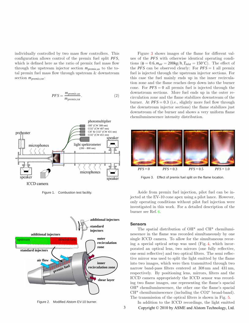
individually controlled by two mass flow controllers. Thisconfiguration allows control of the premix fuel split PFS,which is defined here as the ratio of premix fuel mass flowthrough the upstream injector section mpremix,us to the to-tal premix fuel mass flow through upstream & downstreamsection mpremix,tot :
PFS =mpremix,us
mpremix,tot. (2)
photomultiplier
light spektrometer(200 – 800 nm)
OH* (CW 308 nm)CO2* (CW 407 nm)CH* & CO2* (CW 431 nm)CO2* (CW 451 nm)
Figure 1. Combustion test facility.
shear layer
innerrecirculation zone
outerrecirculationzone
air flow
premix fuel
standardinjectors
additional injectors
upstream downstream
standard injectors
additional injectors
Figure 2. Modified Alstom EV-10 burner.
Figure 3 shows images of the flame for different val-ues of the PFS with otherwise identical operating condi-tions (φ = 0.6,mair = 200kg/h,Tinlet = 150◦C). The effect ofthe PFS can be observed clearly: For PFS = 1 all premixfuel is injected through the upstream injector sections. Forthis case the fuel mainly ends up in the inner recircula-tion zone and the flame reaches deep down into the burnercone. For PFS = 0 all premix fuel is injected through thedownstream sections. More fuel ends up in the outer re-circulation zone and the flame stabilizes downstream of theburner. At PFS = 0.3 (i.e., slightly more fuel flow throughthe downstream injector sections) the flame stabilizes justdownstream of the burner and shows a very uniform flamechemiluminescence intensity distribution.
PFS = 0 PFS = 0.3 PFS = 0.5 PFS = 1.0
Figure 3. Effect of premix fuel split on the flame location.
Aside from premix fuel injection, pilot fuel can be in-jected at the EV-10 cone apex using a pilot lance. However,only operating conditions without pilot fuel injection wereinvestigated in this work. For a detailed description of theburner see Ref. 6.
SensorsThe spatial distribution of OH* and CH* chemilumi-
nescence in the flame was recorded simultaneously by onesingle ICCD camera. To allow for the simultaneous recor-ing a special optical setup was used (Fig. 4, which incor-porated an optical lens, two mirrors (one fully reflective,one semi reflective) and two optical filters. The semi reflec-tive mirror was used to split the light emitted by the flameinto two images, which were then transmitted through twonarrow band-pass filters centered at 308nm and 431 nm,respectively. By positioning lens, mirrors, filters and theICCD camera appropriately the ICCD sensor was record-ing two flame images, one representing the flame’s spacialOH* chemiluminescence, the other one the flame’s spacialCH* chemiluminescence (including the CO2∗ broad-band).The transmission of the optical filters is shown in Fig. 5.
In addition to the ICCD recordings, the light emitted
33 Copyright © 2010 by ASME and Alstom Technology, Ltd.

ICCD
OH* CH*
opticalband-pass
filters
lens flamemirrors
CW 308nm
CW 431nm
fullyreflective
semireflective
Figure 4. Optical setup for simultaneous recording of the spatial distri-
bution of OH* and CH* chemiluminescence in the flame.
300 400 500 600 7000
20
40
60
80
100
CW 308 nm (OH*)CW 407 nm (CO2*)CW 431 nm (CH*)CW 451 nm (CO2*)
λ in nm
Tr λ
in%
Figure 5. Transmission of the optical band-pass filters.
by the flame was also captured by a fiber optic probe (seeFig. 1).
At the optical probe’s end there is a 1.8mm thick op-tical fiber directed at the flame. The light collected by thisthick fiber was passed on to 210 very small fibers forminga bundle of also 1.8mm thickness via an optical splitter.The 210 small fibers are bundled together in groups of 30to form 7 fiber bundles to which photomultiplier tubes orother optical sensors can be connected. This rather compli-cated set-up of the optical probe ensures that each of theconnected optical instruments receives the same light fromthe flame. However, for this work only five of these sevenbundles were used to connect four photomultiplier tubesand a high-sensitivity light spectrometer to the probe.
The photomultipliers were equipped with narrow band-pass filters centered at 308, 407, 431, and 451 nm. Atthese wavelengths, they captured light from OH∗, the CO2∗broad-band, CH∗ (including the CO2∗ broad-band), andagain only the CO2∗ broad-band chemiluminescence, re-spectively. The optical width of the each optical filterssmaller than +-10nm to prevent overlapping of the band-width range of transmission. The transmission of the in-
dividual filters is shown in Fig. 5. The microphone andphotomultiplier signals were amplified and low-pass filteredat 2 kHz to avoid aliasing. The high-sensitivity light spec-trometer was used to measure the light spectrum of theflame.
A standard photo camera recorded images of the flamewithin the visible area of light. Pressure oscillations inthe combustion chamber were measured using a condensermicrophone placed into the first microphone holder down-stream of the flame.
The Flame Chemiluminescence SpectrumMeasured Light Spectrum
For each burner operating condition the light emissionof the flame was measured using an Ocean Optics QE65000high-sensitivity light spectrometer. The spectrometer in-corporates a Hamamatsu back-thinned detector that is re-sponsive from 200-1100nm, features low readout noise, andcan be cooled with an onboard thermoelectric cooler to re-duce dark noise. As an example, Fig. 6 shows the measuredlight spectrum obtained for the operating conditions, whichwill later be used as the reference conditions (black line).Note that the spectrometer sensitivity and the transmis-sion of the optical probe have been accounted for in thepresented spectrum. The distinct peaks corresponding toOH∗ and CH∗ chemiluminescence are clearly visible, as isthe more distributed CO2∗ chemiluminescence. At 521 nma small peak attributed to C2∗ chemiluminescence can alsobe seen.
300 400 500 600 7000
50
100
λ in nm
I λ(n
orm
aliz
ed)
Figure 6. Flame chemiluminescence spectrum: spectrum obtained from
the light spectrometer (black), fitted black body spectrum (red), and cor-
rected flame spectrum (blue). The black dotted lines indicate the CW
of the employed optical filter. Operating conditions: φ = 0.65, mair =200kg/h,Tinlet = 150C.
4
4 Copyright © 2010 by ASME and Alstom Technology, Ltd.

Black Body CorrectionAdditionally, a steep intensity increase is present above
600nm. This increase is due to heat radiation of the burnerplate, which was within the field of view of the optical probe.To obtain only the flame chemiluminescence spectrum, ablack body radiation spectrum was fitted to the measuredspectrum above 670nm. For this fit the radiation intensityof a black body was assumed to follow Planck’s Law:
Iλ,BB(λ,TBB) = A2hPc2
light
λ5
(e
hPclightλkBTBB −1
)−1
, (3)
where Iλ,BB is the spectral black body radiation, TBB theblack body temperature, A a scaling constant clight the speedof light, hP the Planck constant, and kB the Boltzmann con-stant. The flame spectrum (Fig. 6, blue line) was then ob-tained by subtracting the approximated radiation spectrum(Fig. 6, red line) from the measured spectrum.
In the fitting routine the two unknowns, the scalingconstant A and the black body temperature TBB, were fittedto the flame spectrum. While the scaling constant A wasvery similar for different operating conditions, the approxi-mated black body temperature TBB increased (as expected)with the heat release in the flame (i.e., with increasing fuelmass flow), indicating a hotter burner plate. For the flamespectrum presented in Fig. 6 TBB was approximated to be1050K, which is in the order of the expected surface tem-perature of the burner plate, thus giving confidence into thecorrection approach.
Subtraction of the CO2∗ Contribution in the FlameSpectrum
In this work the equivalence ratio of the flame is relatedto the ratio of CH∗ to OH∗ chemiluminescence intensity.Since in the flame spectrum the CH∗ chemiluminescencepeak is superimposed with the broadband CO2∗ emission,the CO2∗ contribution has to be subtracted to obtain onlythe CH∗ emission [7, 8]. To do so, the CO2∗ emission spec-trum is obtained in a second fitting routine. The CO2∗intensity is assumed to follow an ‘extreme’ fit function asproposed by Seipel et al. [7]:
Iλ,CO2 = A · exp
[−exp
(−(λ−λC)w
)− (λ−λC)
w+ 1
], (4)
where Iλ,CO2 is the normalized spectral CO2∗ chemilumines-cence intensity, A a scaling constant, λ the wavelength, λC
the wavelength of maximum intensity, and w a scaling con-stant (in nm) for the width of the extremum. Hence, the
shape of the intensity distribution over the wavelength isonly dependent on the two variables λC and w.
The fit was performed in the wavelength ranges aroundthe CH∗ peak, where only CO2∗ emission is present in thespectrum. Figure 7 presents the flame spectrum togetherwith the fitted CO2∗ contribution and the flame spectrumwithout the CO2∗ contribution for the reference operatingpoint. The fit agrees very well with the background foundin the flame spectrum.
300 400 500 600 7000
50
100
λ in nm
I λ(n
orm
aliz
ed)
Figure 7. Flame chemiluminescence spectrum with extreme fit for the
CO2∗ emission: flame spectrum (blue), CO2∗ fit (green), and flame
spectrum without CO2∗ contribution (magenta). Operating conditions:
φ = 0.65, mair = 200kg/h,Tinlet = 150C.
By subtracting the approximated CO2∗ contributionfrom the flame spectrum the CH∗ peak is isolated at ap-proximately 431 nm. By integrating the spectral CH∗ in-tensity over the wavelength the absolute CH∗ intensity canbe computed:
ICH =∫
λCH
Iλ,CH dλ =∫
λCH
(Iλ, f lame − Iλ,CO2
)dλ, (5)
where λCH indicates the wavelength range in which CH∗chemiluminescence occurs.
In the same way the absolute OH∗ intensity can be ob-tained by integrating the spectral OH∗ intensity. Note, how-ever, that since the CO2∗ is approximately zero within thewavelength range of OH∗ chemiluminescence, no correctionfor CO2∗ emission is required:
IOH =∫
λOH
Iλ,OH dλ. (6)
Figures 8 and 9 present the change of chemilumines-cence intensity with air mass flow and equivalence ratio.
55 Copyright © 2010 by ASME and Alstom Technology, Ltd.

250 300 350 400 450 500 550180
200
220
0
50
100
inte
nsit
y
λ in nmmair in kgh
Figure 8. Spectral intensity vs. air mass flow (φ=0.65, Tinlet=150◦).
250 300 350 400 450 500 5500.6
0.7
0.80
50
100
150
200
inte
nsit
y
λ in nmφ
Figure 9. Spectral intensity vs. air mass flow (mair=200, Tinlet=150◦).
With the outlined approach the computation of theOH∗ and CH∗ chemiluminescence intensity from the lightspectrometer data is straightforward for a steady flamespectrum. In the case of heat release oscillations (forcedor self-induced), however, the flame spectrum is not goingto be steady. For the frequency range of interest for com-bustion oscillations (i.e., 30 to 500Hz), this is generally notpossible with commercial light spectrometers. The high-sensitivity light spectrometer used in this work, for exam-ple, has a minimal shutter speed of 8 ms, which would allowfrequencies of up to 62.5Hz to be resolved (not accountingfor readout time). Furthermore, the recording times neededto achieve a good signal-to-noise ratio are commonly muchlonger, especially since premix flames feature only low lightemission compared to, for example, diffusion flames. Formost light spectra presented in this work the recording timewas 10 s to fully utilize the buffer limits of the light detec-
tor, although good results were also obtained with record-ing times of 1 s. If the recording time is to be reducedeven further, averaging of multiple recordings is a possi-ble way to maintain a good signal-to-noise ratio. To stillresolve fluctuations using averaging a phase-logged trigger-ing of the spectrometer would have been required, whichwould have dramatically increased the necessary measure-ment time. Therefore, the CH∗ chemiluminescence intensityhad to be obtained using photomultiplier tubes, which offera high gain, low noise and high frequency response.
Subtraction of the CO2∗ Contribution in the PMT Sig-nals
The output voltage UPMT obtained from a photomulti-plier can be expressed as:
UPMT = gPMT
∫ ∞
0
((Iλ, f lame + Iλ,BB
)Trλ,probe Trλ,BP Seλ,PMT
)dλ
+UPMT,dark,(7)
where Trλ,probe and Trλ,BP denote the spectral transmissionof the fiber optic probe and the optical bandpass filter, re-spectively, and Seλ,PMT the spectral sensitivity of the PMT.gPMT represents the PMT gain, which was hold constant foreach PMT throughout the whole test campaign. The darksignal UPMT,dark of all PMTs was adjusted to zero before thefirst measurement by applying an offset voltage.
Since the probe transmission and the PMT sensitivityare approximately constant within the narrow wavelengthrange of transmission of the employed optical band passfilters, they can be combined with the gain gPMT to a newgain GPMT . Also, the black body radiation is approximatelyzero within the range of the band pass filters:
GPMT = gPMT
∫λBP
(Trλ,probe Seλ,PMT
)dλ, (8)
UPMT = GPMT
∫λBP
(Iλ, f lame Trλ,BP
)dλ, (9)
where λBP denotes the band pass filter’s wavelength rangeof transmission, i.e., approximately 299 to 318nm in caseof the CW308nm band pass filter (299nm < λCW308 <318nm).
As a measure for the OH∗ chemiluminescence inten-sity the output voltage of the PMT equipped with the
66 Copyright © 2010 by ASME and Alstom Technology, Ltd.

CW308nm band pass filter was used. As stated earlier,the signal does not have to be corrected for CO2∗, since noCO2∗ emission is present within the wavelength range ofthis optical filter. To obtain a signal that only representsthe CH∗ intensity, however, a combination of light spec-trometer and PMT measurements with a steady flame isrequired to account for the CO2∗ emission captured by theCW431nm filter.
According to Eq. (9) the output voltage of thePMTCW431 can be expressed as:
UCW431 = UCH,CW 431 +UCO2,CW431
= GCW431
∫λCW431
(Iλ,CH + Iλ,CO2
)Trλ,CW431 dλ, (10)
where UCH,CW 431 and UCO2,CW431 represent the contributionof CH* and CO2* to the total output voltage of PMTCW431.
Since the (normalized) spectral intensities, the filtertransmission, and the output voltage are known, the gainGCW431 can be determined. Once the gain is known the out-put voltage UCW431 can be separated into its CH∗ and CO2∗contribution:
UCH,CW 431 = GCW431
∫λCW431
Iλ,CH Trλ,CW431 dλ (11)
UCO2,CW431 = GCW431
∫λCW431
Iλ,CO2 Trλ,CW431 dλ. (12)
Since the CO2∗ intensities acquired at center wave-lengths of 407, 431 and 451nm are proportional to eachother, UCO2,CW431 can be related to the output voltages ac-quired at the other two wavelength ranges by two propor-tionality constants CCO2,CW407 and CCO2,CW451:
UCO2,CW431 = CCO2,CW 407UCW407 (13)
UCO2,CW431 = CCO2,CW451UCW451. (14)
The proportionality constants do not only relate thePMT output voltages to each other, but also the integralchemiluminescence intensities, which can be computed fromthe spectrometer data:
ICO2,CW431 = CCO2,CW407ICO2,CW407 (15)
ICO2,CW431 = CCO2,CW451ICO2,CW451, (16)
where the integral CO2* intensity for each band pass filteris given by ICO2,BP =
∫λBP
Iλ,CO2Trλ,BP dλ. The spectral CO2*intensity and the filter transmissions are known, the propor-tionality constants can been determined, and UCO2,CW431 canbe obtained from either the UCW407 or the UCW451 PMT sig-nal. In this work the CH∗ signal was determined using theaverage of the CO2∗ contributions at 431nm obtained fromEqs. (13) and (14).
Note that the proportionality constants are also validfor an unsteady flame with chemiluminescence intensityfluctuations. Hence, the described approach is not limitedto steady flames and the CO2∗ contribution in an unsteadyflame and hence unsteady UCW431 signal could be subtractedto obtain UCH,CW 431.
SPATIAL CHEMILUMINESCENCE INTENSITY SIGNALSUsing the ratio of global OH* and CH* intensity of a
flame as a measure of the flame’s global heat release is onlyexact, if the flame features a uniform spacial equivalenceratio distribution across the flame front. This is due tothe non-linear relationship between the flame chemilumi-nescence intensity and the equivalence ratio. For perfectlypremixed flames the spacial equivalence ratio distributionacross the flame front is uniform per definition. A techni-cally premixed flame like the one investigated in this workis typically not perfectly premixed, but can be assumed tobe quasi premixed. If the standard deviation of the spacialequivalence ratio distribution is only small, the use of globalchemiluminescence measurements is still justified.
To assess the flame’s spacial equivalence ratio distribu-tion the spacial OH* and CH* intensity has been recordedsimultaneously on one ICCD camera detector using the set-up sketched in Fig. 4. The recording was performed forφ = 0.6,mair = 200kg/h,Tinlet = 150◦C and a PFS of 0.3.
Figure 10 shows the obtained OH* and CH* intensitydistribution. A gray color map is used with white indicationthe maximum intensity and darker colors indication lowerintensity. All points with an intensity lower then 15% ofthe maximum intensity are plotted in black to highlight thecontour of the flame. A clear spacial distribution of thechemiluminescence intensities is visible. The OH* and CH*intensity distribution is very similar. Note that the CH*intensity as measured by the ICCD camera also includesthe chemiluminescence contribution of CO2*.
From the spacial distribution of OH* and CH* inten-sity the spacial CH*/OH* ratio is computed. To illustratethe distribution of the spacial CH*/OH* ratio, the relativedeviation of the local to the average CH*/OH* ratio is pre-sented in Fig. 11. The figure shows only small deviations
77 Copyright © 2010 by ASME and Alstom Technology, Ltd.

OH* CH*
Figure 10. Simultaneous OH* (left) and CH* (right) intensity distribution
as recorded by the ICCD camera (φ = 0.6,mair = 200kg/h,Tinlet =150◦C, PFS of 0.3).
between the local and the average CH*/OH* ratio. Mostareas of the flame have a deviation of 0 - 5% (white) and thehighest deviation is in the range of 15 - 20% in only smallareas. This indicates an approximately uniform equivalencedistribution across the flame front. Hence, the use of globalchemiluminecence measurements appears justified for thisoperating conditions. For premix fuel splits of 0.5 and 1the spacial CH*/OH* ratio distribution was less uniform.Therefore, a PFS of 0.3 was selected for the investigationsof the global chemiluminescence response.
CH*/OH* distribution
00 - 05%
05 - 10%
10 - 15%
15 - 20%
> 20%
00 - 05%
05 - 10%
10 - 15%
15 - 20%
> 20%
Deviation of local CH*/OH*from average CH*/OH*
Figure 11. CH*/OH* ratio distribution as deviation between the local and
the average CH*/OH* ratio.
GLOBAL CHEMILUMINESCENCE INTENSITY SIGNALSCalibration of the Photomultiplier Signals
To obtain the coefficients βOH , βCH , and βCO2 in
I = km∗φβ, (17)
the EV-10 burner was operated at different combustion airmass flow rates (170 to 230kg/h) and equivalence ratios(0.55 to 0.80), while the burner inlet temperature was held
constant at 150◦C. At 24 operating points within this pa-rameter range, the time traces of the flame’s chemilumines-cence were recorded by the photomultipliers. In addition,images of the flame were taken using a standard photo cam-era. Note that when determining the coefficient beta inEq. (17) the scaling factor k are also determined.
Figure 12 shows the recorded images for selected com-binations of air mass flow and equivalence ratios. In theseimages, the mean flow direction is from bottom to top. Theburner plate appears on the bottom as a red glowing discwith the burner exit in the center. The flame is stabilizeddownstream of the burner exit, where its light emission iscompletely captured by the optical probe.
= 0.60 = 0.65 = 0.75
mai
r=
180
kg/
hm
air
= 2
00 k
g/h
mai
r=
220
kg/
h
Figure 12. Photo images of the flame at different air mass flows and
equivalence ratios (Tinlet=150◦).
After the calibration measurements had been per-formed, the constants k and β were determined by fit-ting Eq. (17) to the average chemiluminescence intensitiesof OH∗, CH∗ and CO2∗.
Figure 13 shows the recorded chemiluminescence inten-sity obtained directly from the four photomultipliers to-gether with the corresponding intensity fits. The recordeddata points are indicated by circles. The fit is presented asa surface plot. The color of the data point circles indicatesthe deviation between fit and measurement normalized by
88 Copyright © 2010 by ASME and Alstom Technology, Ltd.

the intensity range of the measurement points. Black cir-cles indicates an error of less than 4%, magenta circles anerror between 4 to 8%. The obtained coefficients k and βare given in Tab. 1 together with the coefficients of deter-mination R2 between each fit and the respective measuredvalues.
Table 1. Coefficients k and β obtained from the calibration measure-
ments and coefficients of determination R2 between fit and measured
values.OH∗ CO2∗ CH∗ & CO2∗ CH∗ CO2∗ CO2∗
CW 308nm CW 407nm CW 431nm CW 431nm CW 431nm CW 451nmk 0.0305 0.0399 0.0606 0.0393 0.0285 0.0457β 2.68 3.15 3.97 5.44 3.16 3.17R2 0.974 0.997 0.944 0.998 0.985 0.982
As can be seen in Fig. 13, the trends found in the mea-sured chemiluminescence intensity are well captured by thefits with relative errors between fit and measurement mainlybelow 4%. This is also evident from the R2-values in Tab.1,which are all very close to 1. The lowest R2-value (0.944)was obtained for the fit of the CW431nm signal, becausethe corresponding signal is a superposition of CH* andCO2* intensity. Since the chemiluminescence intensity ofeach species depends differently on the equivalence ratio(i.e., βCH∗ �= βCO2∗), the combined chemiluminescence in-tensity can not be captured perfectly by a fitting functionI = kmairφβ, although the match is still good. For all othersignals, the R2-values is 0.974 or larger, which indicates avery good fit.
As previously mentioned, the PMTs capture only CO2*at CW407nm and CW451nm. Therefore, the dependenceof the two PMT signals on air mass flow and equivalenceratio should be the same (i.e., βCW407 = βCW451). Indeed,the two β coefficients are approximately equal. In contrast,kCW407 and kCW451 cannot be expected to be equal since theydepend on the respective absolute CO2* intensity, the filtertransmission and photomultiplier gain.
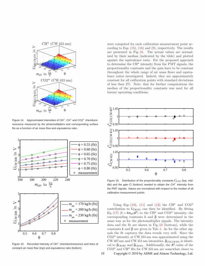
To illustrate the quality of the OH∗ intensity fit in moredetail, Fig. 15 presents the measured OH∗ intensity as afunction of the air mass flow and equivalence ratio togetherwith lines of constant air mass flow and equivalence ratioaccording to the fit. The fit captures the measured trendsvery well. The results confirm the linear dependence of theOH∗ intensity on air mass flow and the exponential depen-dence on equivalence ratio. The measured intensities of CH∗and CO2∗ chemiluminescence (not shown) also match wellwith their fits.
To estimate the CH* intensity signal, the proportional-ity constants CCO2,CW407 and CCO2,CW451 and the gain GCW451
0.50.6
0.70.8
180200
220240
0
2
4
mair in kgh
φ
UP
MT
inV
OH* (CW 308nm)
0.50.6
0.70.8
180200
220240
0
2
4
mair in kgh
φ
UP
MT
inV
CO2* (CW 407nm)
0.50.6
0.70.8
180200
220240
0
2
4
mair in kgh
φ
UP
MT
inV
CH* & CO2* (CW 431nm)
0.50.6
0.70.8
180200
220240
0
2
4
mair in kgh
φ
UP
MT
inV
CO2* (CW 451nm)
Figure 13. Recorded intensities of OH∗, CH∗ and CO2∗ chemilumines-
cence measured by the photomultipliers and corresponding surface fits
as a function of air mass flow and equivalence ratio.
9
9 Copyright © 2010 by ASME and Alstom Technology, Ltd.
0.50.6
0.70.8
180200
220240
0
2
4
mair in kgh
φ
CH* (CW431nm)
UC
H,C
W43
1in
V
0.50.6
0.70.8
180200
220240
0
2
4
mair in kgh
φ
CO2* (CW431nm)
UC
O2,
CW
431
inV
Figure 14. Approximated intensities of OH∗, CH∗ and CO2∗ chemilumi-
nescence measured by the photomultipliers and corresponding surface
fits as a function of air mass flow and equivalence ratio.
160 180 200 220 2400
1
2
3
4
5
φ = 0.55 (fit)φ = 0.60 (fit)φ = 0.65 (fit)φ = 0.70 (fit)φ = 0.75 (fit)φ = 0.80 (fit)measurement
mair in kgh
UC
W30
8in
V
0.5 0.6 0.7 0.80
1
2
3
4
5
mair
= 170 kg/h (fit)
mair
= 200 kg/h (fit)
mair
= 230 kg/h (fit)
measurement
φ
UC
W30
8in
V
Figure 15. Recorded intensity of OH∗ chemiluminescence and lines of
constant air mass flow (top) and equivalence ratio (bottom)
were computed for each calibration measurement point ac-cording to Eqs. (15), (16) and (9), respectively. The resultsare presented in Fig. 16. The actual values are normal-ized by their median (indicated by the tilde) and plottedagainst the equivalence ratio. For the proposed approachto determine the CH* intensity from the PMT signals, theproportionality constants and the gain have to be constantthroughout the whole range of air mass flows and equiva-lence ratios investigated. Indeed, they are approximatelyconstant for all calibration points with standard deviationsof less then 2%. Note, that for further computations themedian of the proportionality constants was used for allburner operating conditions.
0.95
1
1.05
0.95
1
1.05
0.5 0.6 0.7 0.80.95
1
1.05
φ
CC
O2,
CW
407
CC
O2,
CW
451
GC
W45
1
Figure 16. Distribution of the proportionality constants CCO2 (top, mid-
dle) and the gain G (bottom) needed to obtain the CH∗ intensity from
the PMT signals. Values are normalized with respect to the median of all
calibration measurement points.
Using Eqs. (10), (11) and (12) the CH* and CO2*contribution to UCW431 can then be identified. By fittingEq. (17) (I = kmairφβ) to the CH* and CO2* intensity, thecorresponding constants k and β were determined in thesame way as for the photomultiplier signals. The intensitydata and the fit are shown in Fig. 13 (bottom), while theconstants k and β are given in Tab. 1. As for the other sig-nals the fit captures the data trends very well. Since theCO2* intensity at CW431nm was approximated using theCW407nm and CW451nm intensities, βCO2,CW431 is identi-cal to βCW407 and βCW451. Additionally, the R2-value of theCO2* and CH* fits for CW431nm are somewhat closer to
1010 Copyright © 2010 by ASME and Alstom Technology, Ltd.

1 than for the fit of the total PMT voltage. This indicatesthat the measured intensity data better represents the com-bination of two intensity functions, which further increasesthe validity of the used separation approach.
After the CH* intensity has been determined for eachcalibration point, the ICH∗
IOH∗ ratio can be calculated. Fig-ure 17 presents this ratio as a function of the equivalenceratio (bottom). The results for different air mass flows areindicated by different symbols and colors. For compari-son, the ratio of PMT signals UCW 431
UCW 308(i.e., no correction for
CO2*) are plotted as well (top). While both plots showthe typical increase of the ICH∗
IOH∗ ratio with equivalence ra-tio, the ratio of the uncorrected PMT signals shows slightlyshifted trends for different air mass flows, due to the effectof CO2*. When using the isolated CH* signal, however, theresults from all investigated air mass flows fall on one singletrend line. This trend line can be directly obtained from thefitting constants k and β for the OH* and CH* intensity:
ICH
IOH=
kCHmairφβCH
kOHmairφβOH=
kCH
kOHφ(βCH−βOH) (18)
Because the ICH∗IOH∗ ratio is independent of the air mass
flow, it can be used to approximate the equivalence ratio ofthe flame from optical signals only.
SUMMARY & CONCLUSIONSThe relationship between the global CH*/OH* inten-
sity ratio and the global equivalence ratio of a technicallypremixed flame in a swirl-stabilized burner has been inves-tigated. For this investigation a specific premix fuel gasinjection pattern (PFS = 0.3) was selected, since for thisPFS the flame featured an approximately uniform spatialCH*/OH* intensity ratio distribution (and hence an ap-proximately uniform spatial equivalence ratio distribution)and stable combustion.
The global flame chemiluminescence spectrum was mea-sured and corrected for heat radiation of the combustor.The global OH* and CH* chemiluminescence intensitieswere obtained from the spectrum taking into account thesuperposition of CH* and broadband CO2* chemilumines-cence.
A method was developed that uses the spectral flamechemiluminescence results to obtain the global CH*/OH*intensity ratio of the flame from three photomultiplier sig-nals, which measure the flame’s OH*, CO2* and superim-posed CH*+CO2* intensity, respectively. For increased ac-curacy a fourth photomultiplier was employed to obtain asecond CO2* intensity signal.
0.5 0.6 0.7 0.80.8
1
1.2
1.4
1.6
φU
CW
431
UC
W30
8
0.5 0.6 0.7 0.80
0.2
0.4
0.6
0.8
φ
mair = 170 kgh
mair = 180 kgh
mair = 190 kgh
mair = 200 kgh
mair = 210 kgh
mair = 220 kgh
mair = 230 kgh
UC
H,C
W43
1U
CW
308
fit
Figure 17. Variation of the output voltage ratio of PMTCW431 and
PMTCW308 (top, no correction for CO2*) and the ratio of CH* and OH*
intensity (bottom, CH* corrected for CO2*) as obtained from the PMTs
with air flow and equivalence ratio. The used fit function for theICH∗IOH∗ ratio
is kCH∗kOH∗ φ(βCH∗−βOH∗) with values of k and β according to Tab. 1.
The flame chemiluminescence intensity was mapped fora range of equivalence ratios and air mass flows. The map-ping shows that (as stated for perfectly premixed flames inthe literature) the OH*, CH* and CO2* intensity of theinvestigated flame follows Eqn. 1 (I = km∗φβ).
The flame’s global CH*/OH* intensity was shown todepend exponentially on the equivalence ratio and to be in-dependent of the air mass flow. Hence the global CH*/OH*intensity can be employed as a measure of the global equiv-alence ratio for the operating conditions investigated in thiswork. However, the contribution of broadband CO2* chemi-luminescence in the wave length range of CH* chemilumi-
1111 Copyright © 2010 by ASME and Alstom Technology, Ltd.

nescence has to be accounted for. Note that this can onlybe done with at least three photomultipliers and an addi-tional measurement of the flame’s chemiluminescence spec-trum and only works for quasi premix conditions in theflame front.
Although only steady flames were investigated in thiswork, the identified relationship between equivalence ratioand CH*/OH* intensity ratio should also be valid for un-steady flames, provided that a uniform spatial distributionof the equivalence ratio is maintained at all times.
ACKNOWLEDGMENTThe investigations were conducted as part of the joint
research program COOREFF-T in the frame of AG Turbo.The work was supported by the Bundesministerium furWirtschaft und Technologie (BMWi) undergrant number0327710J. The authors gratefully acknowledge AG Turbofor its support and permission to publish this paper. Theresponsibility for the content lies solely with its authors.
REFERENCES[1] Higgins, B., McQuay, M., Lacas, F., Rolon, J., Dara-
biha, N., and Candel, S., 2001. “Systematic mea-surements of oh chemiluminescence for fuel-lean high-pressure, premixed, laminar flames”. FUEL 80, 2001,PP 67-74.
[2] Higgins, B., McQuay, M., Lacas, F., and Candel, S.,2001. “An experimantal study of pressure and strainrate on ch chemiluminescence on premixed fuel-leanmethans /air flames”. FUEL 80, 2001, PP 1583-1591.
[3] Nori, V., and Seitzman, J., 2007. “Detailed distribu-tions of oh*, ch* and c2* chemiluminescence in the re-action zone of laminar methane/air premixed flames”.AIAA-2007-0466 at the 45th Aerospace Sciences Meet-ing, Reno, NV, Jan 8-11, 2007.
[4] Kojima, J., Ikeda, Y., and Nakajima, T., 2000. “De-tailed distributions of oh*, ch* and c2* chemilumines-cence in the reaction zone of laminar methane/air pre-mixed flames”. 36th AIAA/ASME/SAE/ASEE JointPropulsion Conference and Exhibit (2000) AIAA-3394.
[5] Schuermans, B., Guethe, F., Pennell, D., Guyot, D., andPaschereit, C. O., 2009. “Thermoacoustic modeling ofa gas turbine using transfer functions measured at fullengine pressure”. ASME Paper GT2009-59605, Proc.ASME Turbo Expo 2009, Orlando, June 8-12.
[6] Dobbeling, K., Knopfel, H. P., Polifke, W., Winkler, D.,Steinbach, C., and Sattelmayer, T., 1994. “Low NOxPremixed Combustion of MBtu Fuels Using the ABBDouble Cone Burner (EV Burner)”. ASME Paper 94-GT-394.
[7] Seipel, A., Brockhinke, A., and Kohse-Hoinghaus,K., 2009. “Tp3: Spectroscopic characterization andsimulation of chemiluminescence”. 2nd InternationalWorkshop on Chemiluminescence and Heat Release,Munchen.
[8] Lauer, M., and Sattelmayer, T., 2009. “On the ad-equacy of chemiluminescence as a measure for heatrelease in turbulent flames with mixture gradients”.ASME GT2009-59631, Proc. ASME Turbo Expo 2009,Orlando, June 8-12.
12
12 Copyright © 2010 by ASME and Alstom Technology, Ltd.


![USN LM2500 ASME PAPER GT2010-22811 61410 JAL[12]](https://img.pdfslide.us/doc/110x75/5437bc0e219acdf4648b4c05/usn-lm2500-asme-paper-gt2010-22811-61410-jal12.jpg)