Embed Size (px)
Citation preview
GCC CHM 151LL: Geometry of Covalent Compounds © GCC, 2016 Page 1 of 12
CHM 151LL: Geometry of Covalent Compounds
Introduction
Octet Rule
Drawing
Lewis
Electron-Dot
Structures
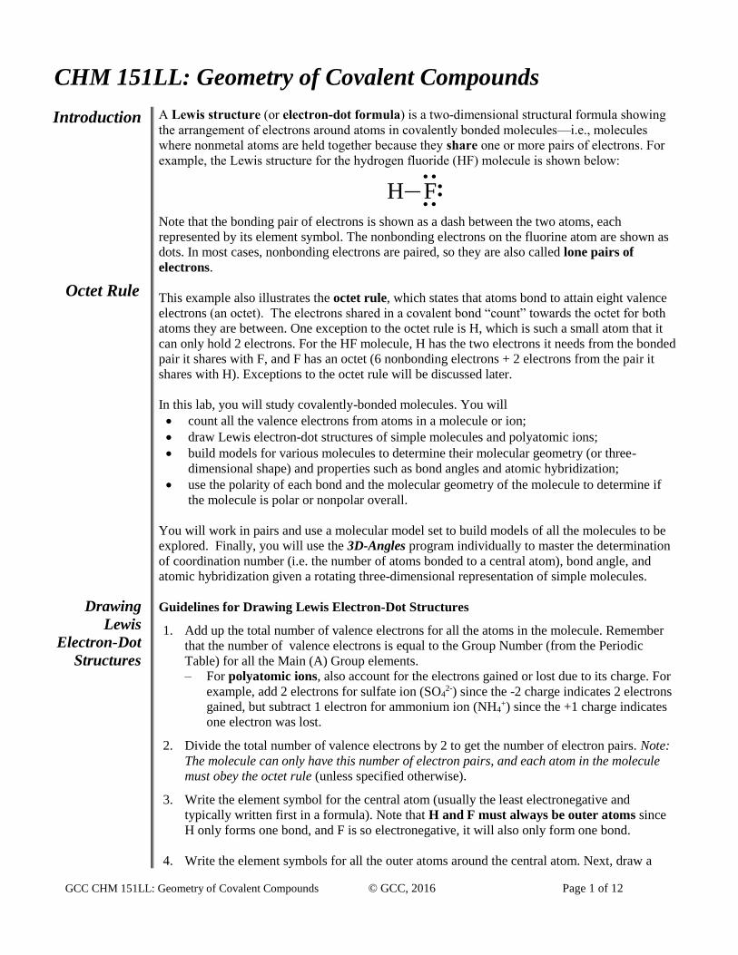
A Lewis structure (or electron-dot formula) is a two-dimensional structural formula showing
the arrangement of electrons around atoms in covalently bonded molecules—i.e., molecules
where nonmetal atoms are held together because they share one or more pairs of electrons. For
example, the Lewis structure for the hydrogen fluoride (HF) molecule is shown below:
H F
..
.. ..
Note that the bonding pair of electrons is shown as a dash between the two atoms, each
represented by its element symbol. The nonbonding electrons on the fluorine atom are shown as
dots. In most cases, nonbonding electrons are paired, so they are also called lone pairs of
electrons.
This example also illustrates the octet rule, which states that atoms bond to attain eight valence
electrons (an octet). The electrons shared in a covalent bond “count” towards the octet for both
atoms they are between. One exception to the octet rule is H, which is such a small atom that it
can only hold 2 electrons. For the HF molecule, H has the two electrons it needs from the bonded
pair it shares with F, and F has an octet (6 nonbonding electrons + 2 electrons from the pair it
shares with H). Exceptions to the octet rule will be discussed later.
In this lab, you will study covalently-bonded molecules. You will
count all the valence electrons from atoms in a molecule or ion;
draw Lewis electron-dot structures of simple molecules and polyatomic ions;
build models for various molecules to determine their molecular geometry (or three-
dimensional shape) and properties such as bond angles and atomic hybridization;
use the polarity of each bond and the molecular geometry of the molecule to determine if
the molecule is polar or nonpolar overall.
You will work in pairs and use a molecular model set to build models of all the molecules to be
explored. Finally, you will use the 3D-Angles program individually to master the determination
of coordination number (i.e. the number of atoms bonded to a central atom), bond angle, and
atomic hybridization given a rotating three-dimensional representation of simple molecules.
Guidelines for Drawing Lewis Electron-Dot Structures
1. Add up the total number of valence electrons for all the atoms in the molecule. Remember
that the number of valence electrons is equal to the Group Number (from the Periodic
Table) for all the Main (A) Group elements.
– For polyatomic ions, also account for the electrons gained or lost due to its charge. For
example, add 2 electrons for sulfate ion (SO42-) since the -2 charge indicates 2 electrons
gained, but subtract 1 electron for ammonium ion (NH4+) since the +1 charge indicates
one electron was lost.
2. Divide the total number of valence electrons by 2 to get the number of electron pairs. Note:
The molecule can only have this number of electron pairs, and each atom in the molecule
must obey the octet rule (unless specified otherwise).
3. Write the element symbol for the central atom (usually the least electronegative and
typically written first in a formula). Note that H and F must always be outer atoms since
H only forms one bond, and F is so electronegative, it will also only form one bond.
4. Write the element symbols for all the outer atoms around the central atom. Next, draw a
GCC CHM 151LL: Geometry of Covalent Compounds © GCC, 2016 Page 2 of 12
Double and
Triple Bonds
Exceptions to
the Octet Rule
Free
Radicals
straight line to connect each outer atom to the central atom. Subtract the number of bonds
drawn from the total number of electron pairs in the structure.
5. Distribute the remaining valence electrons in pairs, first around the outer atoms then around
the central atom, so each atom has an octet.
If there are not enough electrons for each atom to have an octet, then move a
nonbonding (lone) pair of electrons to be shared between 2 atoms, resulting in a double
bond (2 pairs of electrons shared). If additional electrons are still required, move another
pair of electrons to be shared, resulting in a triple bond (3 pairs of shared electrons). Do
not draw double or triple bonds if there are enough valence electrons for each atom
to attain an octet using single bonds.
In some cases, the central atom may get more than an octet. Molecules with an
“expanded octet” are discussed below.
6. For polyatomic ions, square brackets are drawn around the entire Lewis structure, and the
polyatomic ion’s charge is placed in the upper right-hand corner outside the brackets to
indicate the overall charge is spread out among all the atoms in the ion.
In some molecules or polyatomic ions, the central atom may have less than an octet or more than
an octet. These Exceptions to the Octet Rule are described below:
Molecules with Incomplete Octets
Beryllium (Be) and boron (B) can form molecules in which Be only has 4 electrons and B only
has 6 electrons. (These compounds are unstable and often react immediately with other atoms or
compounds, so Be or B will ultimately get an octet, but these molecules do exist for a short time
with less than an octet.)
Molecules with an odd number of electrons:
A few molecules will have an odd number of electrons. These compounds are called free
radicals and are extremely unstable and reactive. They tend to react with other free radicals to
pair up their unpaired electrons. The molecules included in this experiment that are free
radicals will always have nitrogen as the central atom, and in these molecules, the nitrogen
atom will only have 7 electrons.
Molecules with Expanded Octets
Many molecules and polyatomic ions have more than eight valence electrons around the central
atom. The central atom can have an expanded octet only if it is from Period 3 or higher, where
empty d orbitals are available to hold these additional valence electrons. For example, sulfur can
form molecules with an expanded octet because it is in the 3rd period, but oxygen cannot because
it is in the 2nd period and is too small to hold more than an octet.
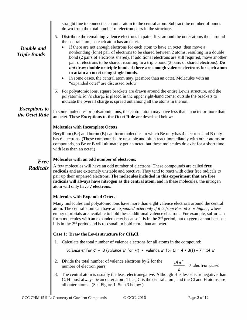
Case 1: Draw the Lewis structure for CH3Cl.
1. Calculate the total number of valence electrons for all atoms in the compound:
valence e– for C + 3 (valence e– for H) + valence e– for Cl = 4 + 3(1) + 7 = 14 e–
2. Divide the total number of valence electrons by 2 for the
number of electron pairs: pairs electron7 2
-e 14=
3. The central atom is usually the least electronegative. Although H is less electronegative than
C, H must always be an outer atom. Thus, C is the central atom, and the Cl and H atoms are
all outer atoms. (See Figure 1, Step 3 below.)
GCC CHM 151LL: Geometry of Covalent Compounds © GCC, 2016 Page 3 of 12
4. Next, we connect all the atoms with single bonds. (See Figure 1 Step 4 below.)
7 electron pairs – 4 bonding pairs = 3 electron pairs left
5. The C atom already has an octet, and each H atom has a pair of electrons, so they need no
additional electrons. The last three pairs are put around the Cl, so it also has an octet. Now C
and Cl each have an octet, and each H has the pair of electrons needed. Thus, the Lewis
electron-dot structure for CH3Cl is shown below.
6. Finally, confirm that electrons were neither created nor destroyed – that there are in fact 14
electrons, no more or less, in the final Lewis structure.
Figure 1. Drawing the Lewis structure for CH3Cl
Step 3 Step 4 Step 5
H C Cl
H
H
H C Cl
H
H
H C Cl
..
.. ..
H
H
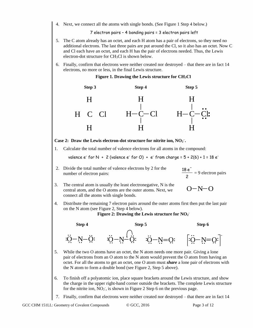
Case 2: Draw the Lewis electron-dot structure for nitrite ion, NO2–.
1. Calculate the total number of valence electrons for all atoms in the compound:
valence e– for N + 2 (valence e– for O) + e– from charge = 5 + 2(6) + 1 = 18 e–
2. Divide the total number of valence electrons by 2 for the
number of electron pairs: 2
-e 18 = 9 electron pairs
3. The central atom is usually the least electronegative, N is the
central atom, and the O atoms are the outer atoms. Next, we
connect all the atoms with single bonds.
4. Distribute the remaining 7 electron pairs around the outer atoms first then put the last pair
on the N atom (see Figure 2, Step 4 below).
Figure 2: Drawing the Lewis structure for NO2-
Step 4 Step 5 Step 6
..
.... ....
..O N O..-
..
.... ....O N O......
.... ..
..
..O N O ..
.... ....O N O..
5. While the two O atoms have an octet, the N atom needs one more pair. Giving a lone
pair of electrons from an O atom to the N atom would prevent the O atom from having an
octet. For all the atoms to get an octet, one O atom must share a lone pair of electrons with
the N atom to form a double bond (see Figure 2, Step 5 above).
6. To finish off a polyatomic ion, place square brackets around the Lewis structure, and show
the charge in the upper right-hand corner outside the brackets. The complete Lewis structure
for the nitrite ion, NO2-, is shown in Figure 2 Step 6 on the previous page.
7. Finally, confirm that electrons were neither created nor destroyed – that there are in fact 14
O N O
GCC CHM 151LL: Geometry of Covalent Compounds © GCC, 2016 Page 4 of 12
Resonance
Structures
VSEPR
Model
Applying the
VSEPR
Model to
Determine
Molecular
Geometries
electrons, no more or less, in the final Lewis structure.
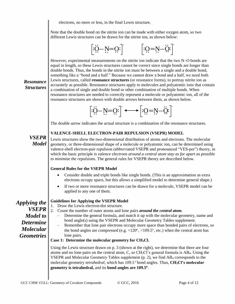
Note that the double bond on the nitrite ion can be made with either oxygen atom, so two
different Lewis structures can be drawn for the nitrite ion, as shown below:
-
..
.... ....O N O..-
..
.... ....O N O..
However, experimental measurements on the nitrite ion indicate that the two N–O bonds are
equal in length, so these Lewis structures cannot be correct since single bonds are longer than
double bonds. Thus, the bonds in the nitrite ion must be between a single and a double bond,
something like a “bond and a half.” Because we cannot draw a bond and a half, we need both
Lewis structures, called resonance structures (or resonance forms), to portray nitrite ion as
accurately as possible. Resonance structures apply to molecules and polyatomic ions that contain
a combination of single and double bond or other combination of multiple bonds. When
resonance structures are needed to correctly represent a molecule or polyatomic ion, all of the
resonance structures are shown with double arrows between them, as shown below.
The double arrow indicates the actual structure is a combination of the resonance structures.
VALENCE-SHELL ELECTRON-PAIR REPULSION (VSEPR) MODEL Lewis structures show the two-dimensional distribution of atoms and electrons. The molecular
geometry, or three-dimensional shape of a molecule or polyatomic ion, can be determined using
valence-shell electron-pair repulsion (abbreviated VSEPR and pronounced “VES-per”) theory, in
which the basic principle is valence electrons around a central atom stay as far apart as possible
to minimize the repulsions. The general rules for VSEPR theory are described below.
General Rules for the VSEPR Model
Consider double and triple bonds like single bonds. (This is an approximation as extra
electrons occupy space, but this allows a simplified model to determine general shape.)
If two or more resonance structures can be drawn for a molecule, VSEPR model can be
applied to any one of them.
Guidelines for Applying the VSEPR Model
1. Draw the Lewis electron-dot structure.
2. Count the number of outer atoms and lone pairs around the central atom.
– Determine the general formula, and match it up with the molecular geometry, name and
bond angle(s) using the VSEPR and Molecular Geometry Tables supplement.
– Remember that lone pair electrons occupy more space than bonded pairs of electrons, so
the bond angles are compressed (e.g. <120, <109.5, etc.) when the central atom has
lone pairs.
Case 1: Determine the molecular geometry for CH3Cl.
Using the Lewis structure drawn on p. 3 (shown at the right), we determine that there are four
atoms and no lone pairs on the central atom, C, so CH3Cl’s general formula is AB4. Using the
VSEPR and Molecular Geometry Tables supplement (p. 2), we find AB4 corresponds to the
molecular geometry tetrahedral, which has 109.5 bond angles. Thus, CH3Cl’s molecular
geometry is tetrahedral, and its bond angles are 109.5.
-
..
.... ....O N O..-
..
.... ....O N O..
GCC CHM 151LL: Geometry of Covalent Compounds © GCC, 2016 Page 5 of 12
H C Cl
..
.. ..
H
H
Electro-
Negativity
Polar
Covalent
Bonds
Nonpolar
Covalent
Bonds
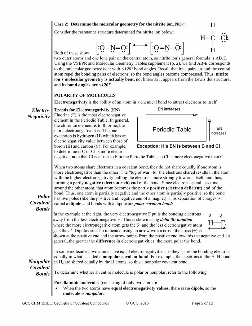
Case 2: Determine the molecular geometry for the nitrite ion, NO2–.
Consider the resonance structure determined for nitrite ion below:
Both of these show
two outer atoms and one lone pair on the central atom, so nitrite ion’s general formula is AB2E.
Using the VSEPR and Molecular Geometry Tables supplement (p. 2), we find AB2E corresponds
to the molecular geometry bent with <120 bond angles. Recall that lone pairs around the central
atom repel the bonding pairs of electrons, so the bond angles become compressed. Thus, nitrite
ion’s molecular geometry is actually bent, not linear as it appears from the Lewis dot structure,
and its bond angles are <120.
POLARITY OF MOLECULES
Electronegativity is the ability of an atom in a chemical bond to attract electrons to itself. Trends for Electronegativity (EN)
Fluorine (F) is the most electronegative
element in the Periodic Table. In general,
the closer an element is to fluorine, the
more electronegative it is. The one
exception is hydrogen (H) which has an
electronegativity value between those of
boron (B) and carbon (C). For example, Exception: H’s EN is between B and C! to determine if C or Cl is more electro-
negative, note that Cl is closer to F in the Periodic Table, so Cl is more electonegative than C.
When two atoms share electrons in a covalent bond, they do not share equally if one atom is
more electronegative than the other. The “tug of war” for the electrons shared results in the atom
with the higher electronegativity pulling the electrons more strongly towards itself, and thus,
forming a partly negative (electron rich) end of the bond. Since electrons spend less time
around the other atom, that atom becomes the partly positive (electron deficient) end of the
bond. Thus, one atom is partially negative and the other atom is partially positive, so the bond
has two poles (like the positive and negative end of a magnet). This separation of charges is
called a dipole, and bonds with a dipole are polar covalent bonds.
In the example at the right, the very electronegative F pulls the bonding electrons
away from the less electronegative H. This is shown using delta () notation,
where the more electronegative atom gets the – and the less electronegative atom
gets the +. Dipoles are also indicated using an arrow with a cross; the cross (+) is
shown at the positive end and the arrow points from the positive end towards the negative end. In
general, the greater the difference in electronegativities, the more polar the bond.
In some molecules, two atoms have equal electronegativities, so they share the bonding electrons
equally in what is called a nonpolar covalent bond. For example, the electrons in the H–H bond
in H2 are shared equally by the H atoms, so this a nonpolar covalent bond.
To determine whether an entire molecule is polar or nonpolar, refer to the following:
For diatomic molecules (consisting of only two atoms):
When the two atoms have equal electronegativity values, there is no dipole, so the
molecule is nonpolar.
-
..
.... ....O N O..-
..
.... ....O N O..
H F
GCC CHM 151LL: Geometry of Covalent Compounds © GCC, 2016 Page 6 of 12
Determine
Molecular
Polarity
Valence Bond
Theory
When the two atoms have different electronegativity values, there is a dipole, so the
molecule is polar.
For molecules of three of more atoms:
The molecule’s polarity depends on the sum of all the bonds’ polarity and the geometry of atoms
around the central atom. A molecule can actually have polar bonds but still be nonpolar overall if
the polar bonds completely cancel out one another. The following guidelines will allow you to
determine whether a molecule is polar or nonpolar:
Guidelines for Determining the Polarity of a Molecule with Three or more Atoms 1. Sketch or build the three-dimensional shape of a molecule. (Note: The two-dimensional
Lewis structure does not provide the three-dimensional arrangement of atoms, so it is not
sufficient for determining whether a molecule is polar or nonpolar.
2. Use the trend for electronegativity values (see p. 5 for details) to determine the more
electronegative atom for each bond on the central atom, then a dipole arrow from the less
electronegative atom to the more electronegative atom.
Note: Since hydrogen’s electronegativity value is between boron’s and carbon’s,
the difference in electronegativity values for hydrogen and carbon is so
small that the carbon-hydrogen bond is considered nonpolar.
3. If the dipole arrows completely cancel one another, the molecule is nonpolar.
If the dipole arrows add up to give an overall or net dipole, the molecule is polar.
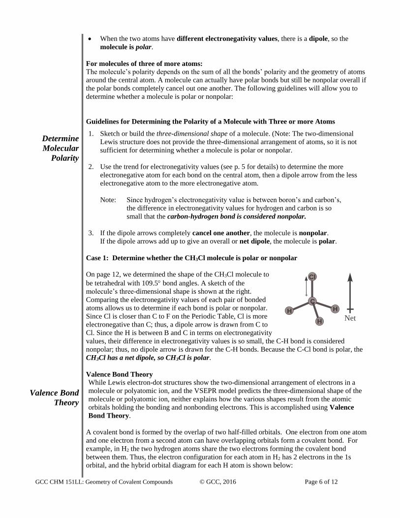
Case 1: Determine whether the CH3Cl molecule is polar or nonpolar
On page 12, we determined the shape of the CH3Cl molecule to
be tetrahedral with 109.5 bond angles. A sketch of the
molecule’s three-dimensional shape is shown at the right.
Comparing the electronegativity values of each pair of bonded
atoms allows us to determine if each bond is polar or nonpolar.
Since Cl is closer than C to F on the Periodic Table, Cl is more
electronegative than C; thus, a dipole arrow is drawn from C to
Cl. Since the H is between B and C in terms on electronegativity
values, their difference in electronegativity values is so small, the C-H bond is considered
nonpolar; thus, no dipole arrow is drawn for the C-H bonds. Because the C-Cl bond is polar, the
CH3Cl has a net dipole, so CH3Cl is polar.
Valence Bond Theory
While Lewis electron-dot structures show the two-dimensional arrangement of electrons in a
molecule or polyatomic ion, and the VSEPR model predicts the three-dimensional shape of the
molecule or polyatomic ion, neither explains how the various shapes result from the atomic
orbitals holding the bonding and nonbonding electrons. This is accomplished using Valence
Bond Theory.
A covalent bond is formed by the overlap of two half-filled orbitals. One electron from one atom
and one electron from a second atom can have overlapping orbitals form a covalent bond. For
example, in H2 the two hydrogen atoms share the two electrons forming the covalent bond
between them. Thus, the electron configuration for each atom in H2 has 2 electrons in the 1s
orbital, and the hybrid orbital diagram for each H atom is shown below:
C
Cl
HH
H
+
Net
GCC CHM 151LL: Geometry of Covalent Compounds © GCC, 2016 Page 7 of 12
Atomic and
Hybrid
Electron Configuration Hybrid Orbital Diagram
for each H in H2: 1s2
1s
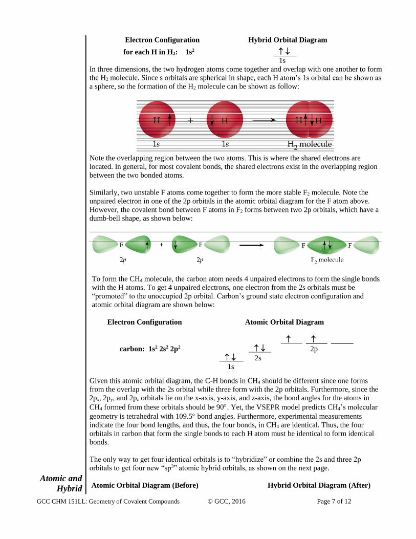
In three dimensions, the two hydrogen atoms come together and overlap with one another to form
the H2 molecule. Since s orbitals are spherical in shape, each H atom’s 1s orbital can be shown as
a sphere, so the formation of the H2 molecule can be shown as follow:
Note the overlapping region between the two atoms. This is where the shared electrons are
located. In general, for most covalent bonds, the shared electrons exist in the overlapping region
between the two bonded atoms.
Similarly, two unstable F atoms come together to form the more stable F2 molecule. Note the
unpaired electron in one of the 2p orbitals in the atomic orbital diagram for the F atom above.
However, the covalent bond between F atoms in F2 forms between two 2p orbitals, which have a
dumb-bell shape, as shown below:
To form the CH4 molecule, the carbon atom needs 4 unpaired electrons to form the single bonds
with the H atoms. To get 4 unpaired electrons, one electron from the 2s orbitals must be
“promoted” to the unoccupied 2p orbital. Carbon’s ground state electron configuration and
atomic orbital diagram are shown below:
Electron Configuration Atomic Orbital Diagram
.
carbon: 1s2 2s2 2p2 2p
2s
1s Given this atomic orbital diagram, the C-H bonds in CH4 should be different since one forms
from the overlap with the 2s orbital while three form with the 2p orbitals. Furthermore, since the
2px, 2py, and 2pz orbitals lie on the x-axis, y-axis, and z-axis, the bond angles for the atoms in
CH4 formed from these orbitals should be 90. Yet, the VSEPR model predicts CH4’s molecular
geometry is tetrahedral with 109.5 bond angles. Furthermore, experimental measurements
indicate the four bond lengths, and thus, the four bonds, in CH4 are identical. Thus, the four
orbitals in carbon that form the single bonds to each H atom must be identical to form identical
bonds.
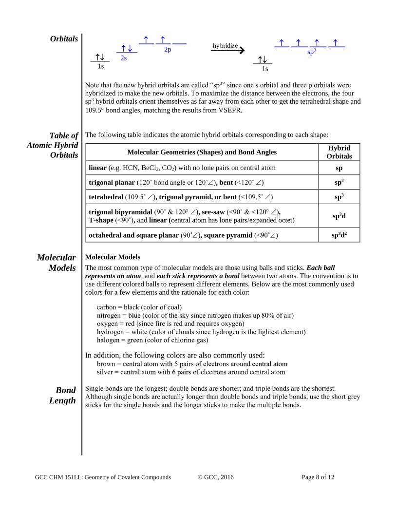
The only way to get four identical orbitals is to “hybridize” or combine the 2s and three 2p
orbitals to get four new “sp3” atomic hybrid orbitals, as shown on the next page.
Atomic Orbital Diagram (Before) Hybrid Orbital Diagram (After)
GCC CHM 151LL: Geometry of Covalent Compounds © GCC, 2016 Page 8 of 12
Orbitals
Table of
Atomic Hybrid
Orbitals
Molecular
Models
Bond
Length
.
2p
2s
1s
hybridize
.
sp3
.
1s
Note that the new hybrid orbitals are called “sp3” since one s orbital and three p orbitals were
hybridized to make the new orbitals. To maximize the distance between the electrons, the four
sp3 hybrid orbitals orient themselves as far away from each other to get the tetrahedral shape and
109.5 bond angles, matching the results from VSEPR.
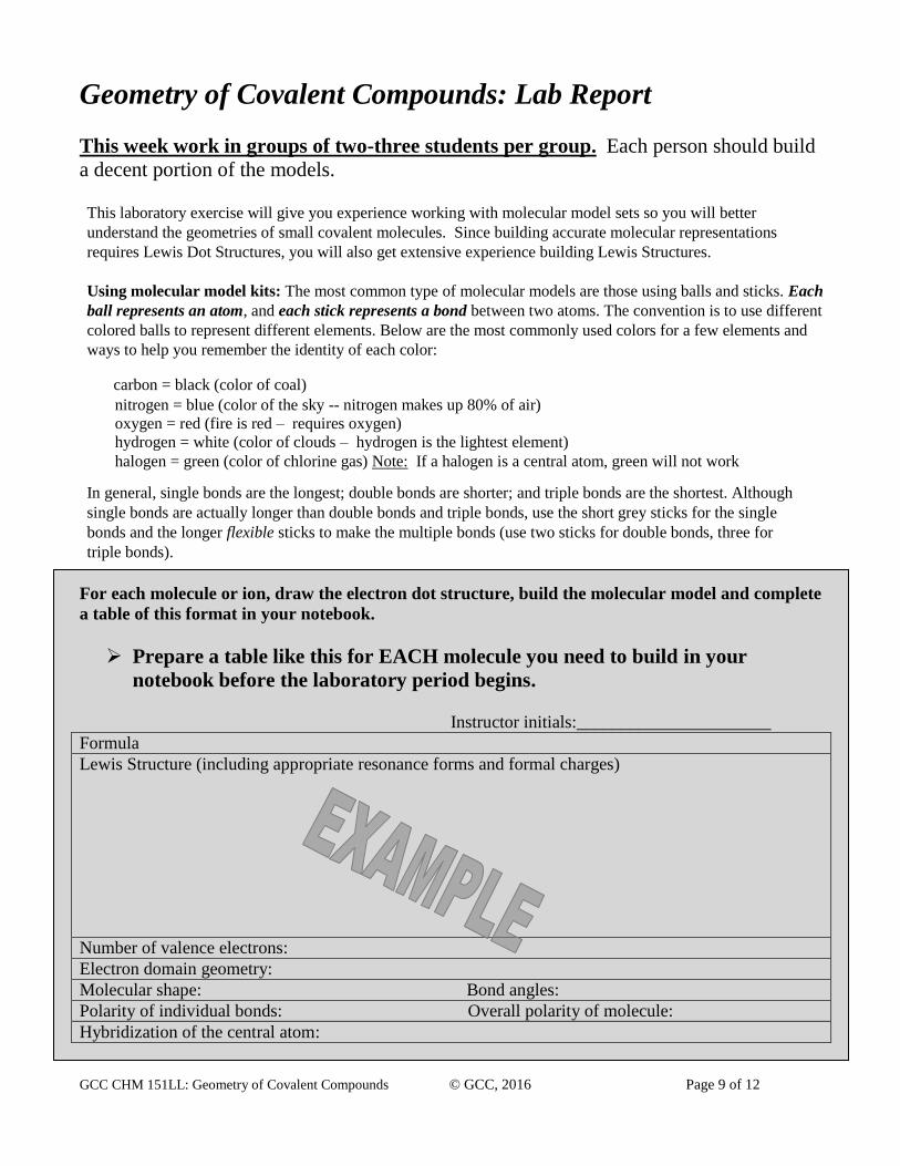
The following table indicates the atomic hybrid orbitals corresponding to each shape:
Molecular Geometries (Shapes) and Bond Angles Hybrid
Orbitals
linear (e.g. HCN, BeCl2, CO2) with no lone pairs on central atom sp
trigonal planar (120˚ bond angle or 120˚), bent (<120˚ ) sp2
tetrahedral (109.5˚ ), trigonal pyramid, or bent (<109.5˚ ) sp3
trigonal bipyramidal (90˚ & 120 ), see-saw (<90˚ & <120 ),
T-shape (<90˚), and linear (central atom has lone pairs/expanded octet) sp3d
octahedral and square planar (90˚), square pyramid (<90˚) sp3d2
Molecular Models
The most common type of molecular models are those using balls and sticks. Each ball
represents an atom, and each stick represents a bond between two atoms. The convention is to
use different colored balls to represent different elements. Below are the most commonly used
colors for a few elements and the rationale for each color:
carbon = black (color of coal)
nitrogen = blue (color of the sky since nitrogen makes up 80% of air)
oxygen = red (since fire is red and requires oxygen)
hydrogen = white (color of clouds since hydrogen is the lightest element)
halogen = green (color of chlorine gas)
In addition, the following colors are also commonly used: brown = central atom with 5 pairs of electrons around central atom
silver = central atom with 6 pairs of electrons around central atom
Single bonds are the longest; double bonds are shorter; and triple bonds are the shortest.
Although single bonds are actually longer than double bonds and triple bonds, use the short grey
sticks for the single bonds and the longer sticks to make the multiple bonds.
GCC CHM 151LL: Geometry of Covalent Compounds © GCC, 2016 Page 9 of 12
Geometry of Covalent Compounds: Lab Report
This week work in groups of two-three students per group. Each person should build
a decent portion of the models. This laboratory exercise will give you experience working with molecular model sets so you will better
understand the geometries of small covalent molecules. Since building accurate molecular representations
requires Lewis Dot Structures, you will also get extensive experience building Lewis Structures.
Using molecular model kits: The most common type of molecular models are those using balls and sticks. Each
ball represents an atom, and each stick represents a bond between two atoms. The convention is to use different
colored balls to represent different elements. Below are the most commonly used colors for a few elements and
ways to help you remember the identity of each color:
carbon = black (color of coal) nitrogen = blue (color of the sky -- nitrogen makes up 80% of air)
oxygen = red (fire is red – requires oxygen) hydrogen = white (color of clouds – hydrogen is the lightest element)
halogen = green (color of chlorine gas) Note: If a halogen is a central atom, green will not work In general, single bonds are the longest; double bonds are shorter; and triple bonds are the shortest. Although
single bonds are actually longer than double bonds and triple bonds, use the short grey sticks for the single
bonds and the longer flexible sticks to make the multiple bonds (use two sticks for double bonds, three for
triple bonds).
For each molecule or ion, draw the electron dot structure, build the molecular model and complete
a table of this format in your notebook.
Prepare a table like this for EACH molecule you need to build in your
notebook before the laboratory period begins.
Instructor initials:______________________
Formula
Lewis Structure (including appropriate resonance forms and formal charges)
Number of valence electrons:
Electron domain geometry:
Molecular shape: Bond angles:
Polarity of individual bonds: Overall polarity of molecule:
Hybridization of the central atom:

GCC CHM 151LL: Geometry of Covalent Compounds © GCC, 2016 Page 10 of 12
When you have built the models of the assigned molecules and ions, show your instructor the models to
make sure you have built them properly. Have your instructor initial each table as you build each model.
Molecules and ions to study, build models for, and record in your notebook:
Water
Sulfur dioxide
Carbonate
Chlorate
Sulfur hexafluoride
Phosphate
Triiodide (I3-)
Pentachloroantimonate (SbCl52-)
Difluoromethane (CH2F2)
Xenon tetrafluoride
Phosphorus pentachloride
Sulfur tetrafluoride

GCC CHM 151LL: Geometry of Covalent Compounds © GCC, 2016 Page 11 of 12
Name:_______________________
Section:___________________
Pre-Lab Questions Write your answers on this page and turn it in
to your instructor before starting this experiment.
1. Determine the total number of valence electrons for each:
a. NH3 ___________
b. NH4+ ___________
c. SO32- ___________
2. How many electron domains do the following molecules have around the central atom?
a. b.
Domains: ______________ Domains: ______________
3. Show delta notation (+ and -) for each of the following bonds and the dipole arrow:
C-O H-Cl N-H C-N
GCC CHM 151LL: Geometry of Covalent Compounds © GCC, 2016 Page 12 of 12
Name:_______________________
Section:___________________
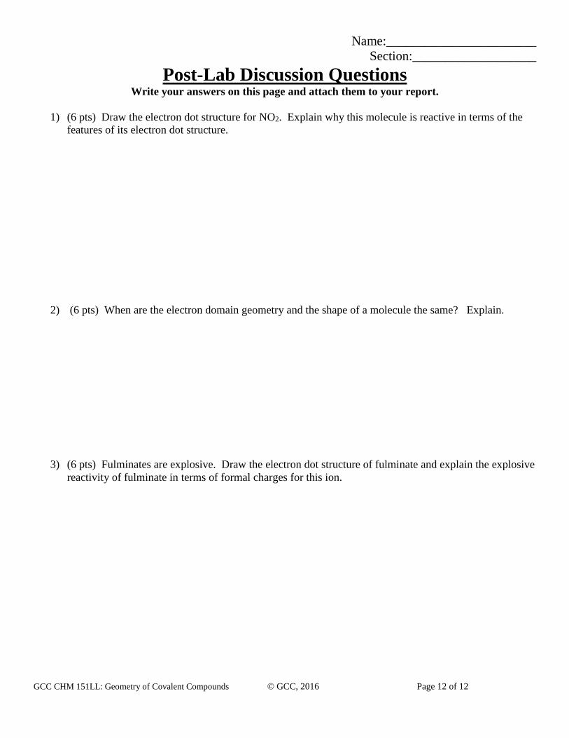
Post-Lab Discussion Questions Write your answers on this page and attach them to your report.
1) (6 pts) Draw the electron dot structure for NO2. Explain why this molecule is reactive in terms of the
features of its electron dot structure.
2) (6 pts) When are the electron domain geometry and the shape of a molecule the same? Explain.
3) (6 pts) Fulminates are explosive. Draw the electron dot structure of fulminate and explain the explosive
reactivity of fulminate in terms of formal charges for this ion.