Embed Size (px)
Citation preview

Secure Power for Hazardous Areas of Offshore Installations
XP90 / XP20 / XPBMS
Chloride® XP

WHEN ONE SPARK CAN TURN YOUR NORMAL DAY INTO A BIG ISSUE
Your challenges Electrical energy can become a danger to daily life on offshore installations that store, process and manufacture hydrocarbons.
Electricity may cause high explosion risk with serious consequences for personnel, equipment and the environment.
As a plant manager, you are solely responsible for the safety of the installation. This includes determining on-site hazardous areas, defining zone boundaries, knowing the characteristics of flammable substances present on site, etc. Obviously, you expect from the contractors as well as the equipment manufacturers that they meet your safety requirements.
When it comes to designing the electrical distribution on an offshore Oil & Gas installation, the way the level of safety per zone is defined plays an important role on many other aspects of the installation.
At the end, you need to be confident that:
yy The operators will be able to do the job safely, at all time
yy The safety of the process will be guaranteed
yy The targeted production performance will be met
yy The installation assets will be protected
yy Your insurance policy will provide total coverage
yy The risks will be appropriately managed.
Electrical energy plays an important role in your daily life, whether you are involved in studying, designing or implementing oil & gas installations.
What you need An Uninterruptible Power Supply (UPS) solution to fit your application
At Vertiv, we have developed in-house expertise to bring our UPS Solution competencies to the ‘Ex’ applications.
Chloride® XP systems are tailor-made solutions designed to operate in the hazardous atmosphere. Our solutions include:
yy Ex d dual redundant DC UPS systems up to 30kW
yy Ex d dual redundant AC UPS systems up to 15kVA
yy Ex d single DC UPS systems up to 15kW
yy Ex de AC and DC distribution panels
yy Ex d Charger Controller Unit (CCU) with Maximum Power Point Tracker (MPPT) technology for solar arrays
yy Ex e Battery cabinets
yy Ex d Wall mounted battery circuit protection boxes
yy Ex e Battery Monitoring System
INCREASED SAFETY EX e OR FLAMEPROOF EX d UPS SOLUTIONSTO SECURE POWER IN HARZARDOUS AREAS
The highly critical applications at offshore Oil & Gas installations need to be secured by reliable and uninterrupted power.
Compliance to ATEX/IECex
Chloride® XP systems from VERTIV are designed to meet the requirements of the ATEX/IECex standards:
yy Ability to self-contain an inside explosion
yy Acceptance of over-pressure routine tests at 1.5 time calculated test pressure
Adaptability to project needs
Chloride® XP UPS systems are designed in compliance with your ATEX/IECex project specific requirements.
The electrotechnical design is based on our proven range of systems: Ability to self-contain an inside explosion
yy Chloride® XP20R is built with Chloride® FP20R high frequency switch-mode charger.
yy Chloride® XP90R is built with our SCRbased chargers of Chloride® CP70R range
yy Chloride® XP90Z is based on our SCR/ IGBT AC UPS systems of Chloride® CP70Z range.
The enclosure is designed to best fit your application with a choice of materials and mechanical configurations:
yy Stainless steel or Carbone steel enclosure (XP90)
yy Aluminum enclosure (XP20R & XP90)
yy Baseframe ready to be bolted or welded
yy Sunshade canopy
yy Specific mechanical adaptation to meet footprint constraints

PROJECT MANAGEMENT FOR THE COMPLETE CYCLE
Feasibility Study Our consulting engineers work alongside you, from FEED to EPC, to analyze your oil and gas project data, including:
yy Existing technical specification, if any
yy Low voltage electrical distribution network analysis
yy Load flow studies and load shedding
yy Short-circuit analysis
yy Power quality analysis
yy Noise rejection analysis (Harmonic current and voltage distortion)
yy Grounding/Neutral networking
yy Failure modes and effects analysis
yy Battery type and configuration under all load, environmental and aging conditions
yy Mechanical environment
yy Health and safety requirements
From project conceptual study to the procurement stage, you need special skills for the Explosion-proof power protection part of your project
System Design Our application engineers support you in conceptualizing your system needs by:
yy Understanding the on-site needs for proper installation and operation
yy Clarifying the technical specification if needed
yy Submitting a technical and commercial offer
yy Supplying all the relevant calculation notes, e.g. battery calculation as per required environmental conditions
yy Providing the statement of compliance
yy Providing a detailed draft of technical solutions, including the single line diagrams and general arrangement drawings
yy Answering all the technical queries you may have
Mechanical stress simulation Pressure tests

...NO MATTER THE CHALLENGE!
Project Management Our project management teams are fully accountable for:
yy Submitting timely drawings as per agreed supplier document schedule
yy Providing timely documentation as per customer specifications
yy Ensuring adjustments are fulfilled accordingly with customer’s expectations and defined scope of supply
yy Providing the best technical advice for revised requirements
yy Ensuring factory acceptance tests are 100 % compliant with our customer’s requests
yy Handling packing and logistics issues
yy Understanding the project commissioning requirements
Services To ensure system start-up is achieved ontime, our Start-up services include:
yy Product warranty extensions
yy Supervision of installation
yy Systems commissioning and testing
yy Project training
yy Load bank rental and supply
yy Commissioning spare parts
To ensure the complete reliability of the system over its entire lifetime, our Operate and Maintain services include:
yy Spare parts
yy Preventive maintenance
yy Repair services and third-party maintenance
yy Site maintenance training
yy Shutdown and turnaround services
yy System upgrades
3D design Offshore services

(1) other available upon request
CHLORIDE® XP90REX d RECTIFIERS - CHARGERS
HIGHLIGHTS
yy Small footprint - High power DC UPS system available in small size to optimize space on offshore platform
yy Optimized thermal management - Chloride® XP90R uses our latest patented Exd enclosure cooling system
yy Strong immunity to perturbations - Chloride® XP90R integrates an isolating input transformer
yy Safe control, door closed - Chloride® XP90R allows the user to operate the switches and circuit breakers, as well as the control buttons with door closed
yy Smart access to UPS data: - Large graphical user interface providing access with door closed - Embedded event logger (up to 2000 events)
yy Safe and easy maintenance - Once open, the front door gives access to all internal components from the front
RATINGS (A) VS DC OUTPUT VOLTAGE (VDC)
125 A 250 A 500 A
24 Vdc
48 Vdc
INPUTAC voltage 3 x 400 V (380, 415)(1)
Voltage tolerance +/- 10 %Frequency 50 Hz (60 Hz)Frequency tolerance +/- 5 %
OUTPUTDC voltage (nominal) 24 / 48 V (1)
Voltage stability (Input within tolerance)
+/- 1 % in float mode +/- 1.5 % for parallel rectifiers
Voltage ripple 0.1 % RMS, in float mode, battery connectedCurrent limitation I nominal / up to 150 % for 1 minuteCharging characteristic IU according to DIN 41773
BATTERYType Valve Regulated Lead Acid (VRLA)
Recombination Nickel CadmiumAutonomy From few minutes to several hours, as per
customer’s requirementBattery current limitation (typical, float mode)
0.1 C (Lead Acid or Nickel Cadmium battery)
Battery temperature compensation
-3 mV/°C/cell
GENERAL DATAOperating temperature up to 55 °CRelative humidity 100 %, condensingOperating altitude 1000 m max without deratingCooling NaturalEfficiency Up to 90 % according to rating and
configuration
ENCLOSUREDesign ATEX/IECex certified for
Zone1, II 2G Ex d IIB+H2 T3 (IEC 60079)Material Stainless steel (SS316L),
Carbon steel (mild steel) or AluminumExternal ingress protection IP 66 according to IEC 60529Dimensions Varying according to ratings & options
Technical Data

CHLORIDE® XP90ZEX d AC UPS SYSTEMS
HIGHLIGHTS
yy Small footprint - High power AC UPS system available in small size to optimize space on offshore platform
yy Optimized thermal management - Chloride® XP90Z uses our latest patented Exd enclosure cooling system
yy Strong immunity to perturbations - Chloride® XP90Z integrates isolating input (charger) and output (inverter) transformers
yy Safe control, door closed - Chloride® XP90Z allows the user to operate the switches and circuit breakers, as well as the control buttons with door closed
yy Smart access to UPS data: - Large graphical user interface providing access with door closed - Embedded event logger (up to 2000 events)
yy Safe and easy maintenance - Once open, the front door gives access to all internal components from the front
RATINGS (A) VS DC OUTPUT VOLTAGE (VDC)
110 Vdc 5 kVA 10 kVA 15 kVA
INPUTAC voltage 3 x 400 V (380, 415)(1)
Voltage tolerance +/- 10 %Frequency 50 Hz (60 Hz)Frequency tolerance +/- 5 %
OUTPUTAC voltage (nominal) 1 x 230 V (220, 240) ; 1 x 110V (115, 120)(1)
3 x 400 V (380, 415)(1)
Frequency 50 Hz (60 Hz)Overload inverter: • 1 minute • 10 minutes
150 % of nominal power 125 % of nominal power
Short circuit clearance: • 1-ph output (in % of nominal current) • 3-ph output (in % of nominal current)
250 %/100 ms - 175 %/5 s 315 %/100 ms - 220 %/5 s (Ph-N)
Power factor 0.8 laggingAllowable crest factor 3/1
BATTERYType Valve Regulated Lead Acid (VRLA)
Recombination Nickel CadmiumAutonomy From few minutes to several hours, as per
customer’s requirementBattery current limitation (typical, float mode)
0.1 C (Lead Acid or Nickel Cadmium battery)
Battery temperature compensation
-3 mV/°C/cell
GENERAL DATAOperating temperature Up to 55 °CRelative humidity 100 %Operating altitude 1000 m max without deratingCooling NaturalEfficiency Up to 85 % according to rating and
configuration
ENCLOSUREDesign ATEX/IECex certified for
Zone1, II 2G Ex d IIB+H2 T3 (IEC 60079)Material Stainless steel (SS316L) or
Carbon steel (mild steel)External ingress protection IP 66 according to IEC 60529Dimensions Varying according to ratings & options
Technical Data
(1) other available upon request
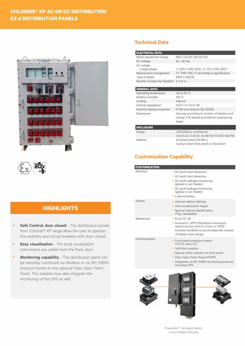
CHLORIDE® XP AC OR DC DISTRIBUTIONEX d DISTRIBUTION PANELS
HIGHLIGHTS
yy Safe Control, door closed - The distribution panels from Chloride® XP range allow the user to operate the switches and circuit breakers with door closed
yy Easy visualisation - The local visualisation instruments are visible from the front, door
yy Monitoring capability - The distribution panel can be remotely monitored via Modbus or via IEC 61850 protocol thanks to the optional Fiber Optic Patch Panel. This solution may also integrate the monitoring of the UPS as well
ELECTRICAL DATARated operational voltage 690 V AC/DC (50-60 Hz)DC voltage 24 / 48 VdcAC voltage: • single phase
1 x 230 V (220, 240) ; 1 x 110 V (115, 120)(1)
Neutral point arrangement TT, TNS, TNC, IT according to specificationType of feeder MCB or MCCBNumber of poles (for feeders) 2, 3 or 4
GENERAL DATAOperating temperature -25 to 55 °CRelative humidity 100 %Cooling NaturalInternal segregation Form 1 or Form 2BExternal ingress protection IP 66 according to IEC 60529Dimensions Varying according to number of feeders and
ratings. Full details provided at engineering stage
ENCLOSUREDesign ATEX/IECex certified for
Zone1 & 2, II 2G Ex de IIB+H2 T3 (IEC 60079)Material Stainless steel (SS316L),
Carbon steel (mild steel) or Aluminum
Technical Data
CUSTOMIZATIONElectrical yy DC earth fault detection
yy AC earth fault detectionyy DC earth leakage monitoring (global or per feeder)yy AC earth leakage monitoring (global or per feeder)yy Load shedding
System yy Internal cabinet lightingyy Anti-condensation heateryy Special cabinet identification (Tag, nameplate)
Mechanical yy Form 2A, 2Byy Housed in UPS1 Distribution enclosure (above picture with Ex e box) or UPS2 encloser (smaller) to accomodate the number of feeders and ratings
Communication yy Front panel analogue meters (72x72, class 1.5)yy Volt-free contactsyy Special LEDs indicator on front panelyy Fiber Optic Patch Panel (FOPP)yy Integration of IEC 61850 monitoring protocol, including UPS
Customization Capability
PowerplexTM increased safety circuit breaker housing

INCREASED SAFETY EX eBATTERY ENCLOSURES
HIGHLIGHTS
yy ATEX/IECex certified - Enclosure certified for use in Zone 1 and Zone 2 gas hazard areas
yy Easy battery installation - The front panel of the enclosure can be unscrewed to ease the installation of heavy battery cells inside the enclosure
yy Easy maintenance - Once installed, the battery cells can be accessed for normal maintenance and checks using the hinged lid
BATTERYType Valve Regulated Lead Acid (VRLA)
Recombination Nickel CadmiumAutonomy From few minutes to several hours, as per
customer’s requirement
ENCLOSUREMaterial Stainless steel (SS316L)Storage temperature -20 to 70 °CRelative humidity 100 %Design ATEX/IECex certified for
Zone1 & 2External ingress protection IP 56 according to IEC 60529Dimensions Varying according to number of cells and
battery capacity. Full details provided at engineering stage
Technical Data
CUSTOMIZATIONElectrical yy Temperature sensor for compensated batery
charging
Mechanical yy Special cabinet identification (Tag, nameplate)yy Special frame coloryy Removable lids or hinged lidsyy Gas strutsyy Bolted front coveryy Side or rear connection box in stainless steel 316Lyy Side isolator switch box in stainless steel 316L (with PowerplexTM panel board offering component level flamepaths)yy Integration and interconnection of the battery cells at the factory level, prior to delivery, thanks to the highly robust enclosure
Customization Capability
Example of hinged lid design

CHLORIDE® XPEX d OR EX de BATTERY CIRCUIT PROTECTION BOX
HIGHLIGHTS
yy ATEX/IECex certified - the battery circuit protection box is certified for use in Zone 1 and Zone 2 gas hazard areas
yy Versatility of the offering - Customization according to the requirements and the application
yy Black start option - Capability to restart the connected UPS thanks to the overide switch and battery capacity available, after an ESD
BATTERY CIRCUIT PROTECTIONType MCB, MCCB, Fuse, Fuse-switch
ENCLOSURERelative humidity 100 %Design ATEX/IECex certified for
Zone1 & 2Material Stainless steel (SS316L)External ingress protection IP 56 according to IEC 60529
(Stainless steel) IP 65 according to 60529 (Carbon steel)
Dimensions Varying according to requirements. Full details provided at engineering stage
Technical Data
CUSTOMIZATIONElectrical
yy MCB, MCCB, Fuse, Fuse-switch position contact, trip contactyy Shunt tripyy Battery black start (after Emergency shutdown ESD)yy Override feature (ESD reset) via external key switch
Systemyy Internal cabinet lightingyy Anti-condensation heateryy Box identification (Tag, nameplate)
Mechanical yy Top cable entryyy Special frame color
Communication yy Position contactyy Fuse failure contact
Customization Capability
Example of battery circuit protection box with ESD override

CHLORIDE® XPBMSINCREASED SAFETY (EX eb mb) BATTERY MONITORING SYSTEM
HIGHLIGHTS
yy ATEX/IECex certified - Enclosure certified for use in Zone 1 and Zone 2 gas hazard areas
yy Reduced maintenance costs - through preventive maintenance instead of emergency replacement
yy Maximized battery life - through smart diagnostics, regular data analysis and on-time remedial action
yy Increased safety on site as back-up power remains available when most needed and less human presence is required in battery room
BATTERY STRING MEASURE VALUESString voltage range 2V - 600VString current:
• Measurement Range • Number of string current measures
0A - 2000A Up to 5 (scaleable to 16)
String ambient temperature: • Measurement range • Number of measures
0 °C to 50 °C Up to 5. Only 1 sensor per battery room if several strings in the same battery room
BATTERY BLOCKS OR CELLS MEASURED VALUESNumber of monoblocks(1) Up to 160 (scaleable to 1280)Voltage (depending on bat-tery type and m-Senzor type)
From 1 V to 12 V
Impedance(2) (depending on block voltage and m-Senzor)
From 0.15 to 40 mΩ - for Lead Acid batteries ONLY
Temperature(2) From -10 °C to +70 °C
GENERAL DATABattery sensor design Ex eb mb IIC T6Battery room temperature sensor
Ex d IIC T6
Technical Data
CUSTOMIZATIONElectrical yy Compatibility with Lead Acid or Nickel
Cadmiumyy Block by block or cell by cell monitoringyy Ex d Temperature sensor
Mechanical yy Ex d enclosure for monitoring modulesyy Mechanical kit for the installation of Ex e battery sensors on racks
Customization Capability
(1)A monoblock represents one or more battery cells in a container.(2)
Available as option.
Elements of Battery Monitoring System
Ex d box Aluminium) for Temperature Probe
Sentinel Module monitoring Ex m sensors data
Ex m sensor
UNDERSTANDING HAZARDOUS AREAS AND RELATED EQUIPMENT
Definition of hazardous Areas
According to the IEC international standard IEC 60079, a hazardous area is a three dimensional region or space in which an explosive gas atmosphere is, or may be expected to be present, in quantities such as to require special precautions for the construction installation and use of equipment.
Hazardous areas are classified in three zones based upon the frequency of the occurence and duration of an explosive gas atmosphere:
yy Zone 0: Area in which an explosive gas atmosphere is present continuously or for long periods or frequently.
yy Zone 1: Area in which an explosive gas atmosphere is likely to occur occasionally in normal operation.
yy Zone 2: Area in which an explosive gas atmosphere is not likely to occur in normal operation but, if it does occur, will persist for a short period only.
yy Non hazardous area (safe area): A non hazardous area is an area in which an explosive atmosphere is not expected to be present.
The manager of the plant is solely responsible for dertermining the hazardous areas. The electrical engineer can not be the designer of the area classification.
The Chloride® XP range of UPS systems is for use in Zone 1 and Zone 2
Gas and Vapor classification
The IEC defines different groups of gases and vapors, based on how volatile the gas or vapor would be if it was ignited. These groups also indicate how much energy is required to ignite the gas by a spark.
yy Group IIA: Propane, Ethane, Butane, Benzene, Pentane, Heptane, Acetone, Methyl Ethyl, Methyl Alcohol, Ethyl Alcohol
yy Group IIB: Ethylene, Ethyl Ether, Cyclopropane, Butadene 1-3
yy Group IIC: Acetylene, Hydrogen.
yy Group IIC includes the most volatile gas and the one that requires the least energy to ignite.
The Chloride XP range of UPS systems is certified IIB+H2, i.e. suitable for battery protection (MCCB, LVD, ESD reset)
Temperature classification
It is a system of classification by which electrical equipment is assigned one of six temperature classes according to its maximum component surface temperature.
Temperature in °C IEC classification450 T1
300 T2
200 T3
135 T4
100 T5
85 T6
The Chloride® XP range of UPS systems is temperature class T3 (T4 or T5 on request)
Protection modes
The IEC defines several protection modes. The two most common protection modes applicable to UPS are:
yy «d» Flameproof
yy «e» Increased Safety
BETTER UNDERSTANDING LEADS TO BETTER CHOICEVertiv has developed in-house expertise to help you understand all the key points related to increased safety areas. We can help you design the best suited Uninterruptible Power Supply system (UPS) according to the type of hazardous atmosphere.
Increased Safety «e» equipment
An increased safety « e » equipment is designed such that it does not cause arcs or excessive temperatures likely capable of igniting an explosive atmosphere. It prevents any accidental ignition.
Recommendation to install Increased Safety «e» equipment
The equipment has a protection index of at least IP 54 ; it is therefore important to ensure that the weatherproof seal is in good condition when the product is installed. Defective seals must be systematically replaced.
The Battery enclosures and the sensors of the Chloride XP-BMS are Increased Safety «e» equipment
Flameproof «d» equipment
A flameproof enclosure must be able to fulfil three criteria :
yy It contains an internal explosion without permanent distortion.
yy It guarantees that the explosion cannot be transmitted to the surrounding atmosphere.
yy It exhibits a temperature at all points on the surface which is lower than the spontaneous ignition temperature of the surrounding gases or vapors.
Recommendation to install Flameproof «d» equipment
In order to successfully retain the flameproof character of the equipment, care must be taken before starting up to ensure that all the screws for closing the covers and cable entries are firmly tightened. Moreover, modification of the original pre-drilled holes is prohibited.
The Chloride XP ranges of AC UPS, DC UPS and DIstribution panels are Flameproof «d»

VertivCo.com © 2017 Vertiv Co. All rights reserved. Vertiv, the Vertiv logo and Vertiv Liebert DSE are trademarks or registered trademarks of Vertiv Co. All other names and logos referred to are trade names, trademarks or registered trademarks of their respective owners. While every precaution has been taken to ensure accuracy and completeness herein, Vertiv Co. assumes no responsibility, and disclaims all liability, for damages resulting from use of this information or for any errors or omissions. Specifications are subject to change without notice.
Chloride-XP90-DS-EN-gl-rev2-0118
VertivCo - Global headquarters and EMEA
30 avenue Montgolfier – BP90 69684 Chassieu Cedex
France Tel: +33 (0)4 78 40 13 56