Embed Size (px)
Citation preview
Chiron: Concurrent High Throughput Communicationfor IoT Devices
Yan Li∗
Computer Science and Electrical Engineering
University of Maryland, Baltimore County
Johns Hopkins Applied Physics Laboratory
Zicheng Chi∗
Computer Science and Electrical Engineering
University of Maryland, Baltimore County
Xin Liu
Computer Science and Electrical Engineering
University of Maryland, Baltimore County
Ting Zhu
Computer Science and Electrical Engineering
University of Maryland, Baltimore County
ABSTRACTThe exponentially increasing number of heterogeneous Internet of
Things (IoT) devicesmotivate us to exploremore efficient and higher
throughput communication, especially at the bottleneck (i.e., edge)
of the IoT networks. Our work, named Chiron, opens a promising
direction for Physical (PHY) layer concurrent high throughput
communication to heterogeneous IoT devices (e.g., wider-bandWiFi
and narrower-band ZigBee). Specifically, at the PHY layer, Chiron
enables concurrently transmitting (or receiving) 1 stream of WiFi
data and up to 4 streams of ZigBee data to (or from) commodity
WiFi and ZigBee devices as if there is no interference between these
simultaneous connections. We extensively evaluate our system
under different real-world settings. Results show that Chiron’s
concurrent WiFi and ZigBee communication can achieve similar
throughput as the sole WiFi or ZigBee communication. Chiron’s
spectrum utilization is more than 16 times better than the traditional
gateway.
CCS CONCEPTS• Networks→ Network protocol design; Home networks;
KEYWORDSWireless, Concurrent Communication, Internet of things (IoT)
1 INTRODUCTIONInternet-of-Thing (IoT) devices use different radios and modulation
mechanisms (e.g., WiFi, ZigBee, and Bluetooth). Therefore, they
cannot directly communicate with each other. Traditionally, com-
munication between different wireless technologies is achieved
indirectly via gateways equipped with multiple radio interfaces.
∗Both authors contributed equally to the paper
Publication rights licensed to ACM. ACM acknowledges that this contribution was
authored or co-authored by an employee, contractor or affiliate of the United States
government. As such, the Government retains a nonexclusive, royalty-free right to
publish or reproduce this article, or to allow others to do so, for Government purposes
only.
MobiSys ’18, June 10–15, 2018, Munich, Germany© 2018 Copyright held by the owner/author(s). Publication rights licensed to ACM.
ACM ISBN 978-1-4503-5720-3/18/06. . . $15.00
https://doi.org/10.1145/3210240.3210346
WiFiDevice
ZigBeeDevice
WiFi
ZigBee
Gateway
Freq
uenc
y (M
Hz)
2
20
Time
18 MHzSpectrum
Wasted WiF
i
( a ) ( b )
WiF
i
ZigBee
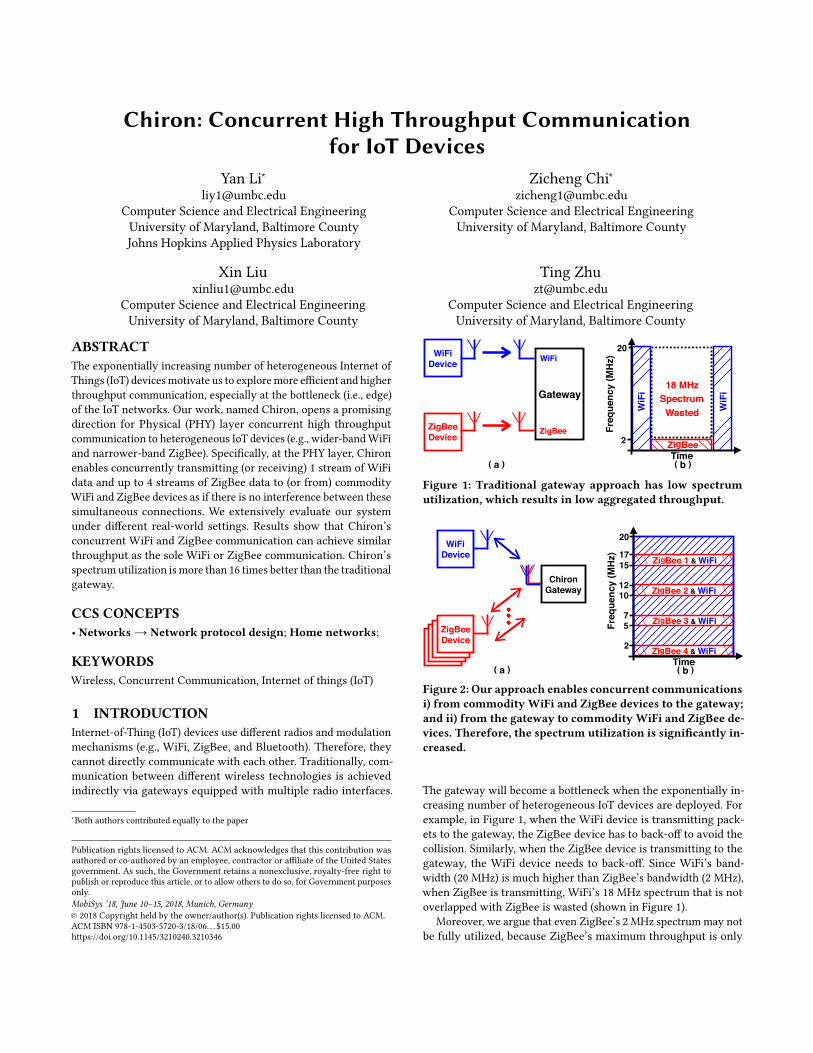
Figure 1: Traditional gateway approach has low spectrumutilization, which results in low aggregated throughput.
Freq
uenc
y (M
Hz)
2
20
Time( b )
57
1012
1517
ZigBee 4 & WiFi
ZigBee 3 & WiFi
ZigBee 2 & WiFi
ZigBee 1 & WiFi
WiFiDevice
ZigBeeDevice
( a )
ChironGateway
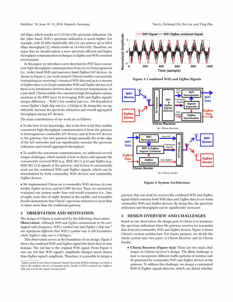
Figure 2: Our approach enables concurrent communicationsi) from commodity WiFi and ZigBee devices to the gateway;and ii) from the gateway to commodity WiFi and ZigBee de-vices. Therefore, the spectrum utilization is significantly in-creased.
The gateway will become a bottleneck when the exponentially in-
creasing number of heterogeneous IoT devices are deployed. For
example, in Figure 1, when the WiFi device is transmitting pack-
ets to the gateway, the ZigBee device has to back-off to avoid the
collision. Similarly, when the ZigBee device is transmitting to the
gateway, the WiFi device needs to back-off. Since WiFi’s band-
width (20 MHz) is much higher than ZigBee’s bandwidth (2 MHz),
when ZigBee is transmitting, WiFi’s 18 MHz spectrum that is not
overlapped with ZigBee is wasted (shown in Figure 1).
Moreover, we argue that even ZigBee’s 2 MHz spectrum may not
be fully utilized, because ZigBee’s maximum throughput is only
MobiSys ’18, June 10–15, 2018, Munich, Germany Yan Li, Zicheng Chi, Xin Liu, and Ting Zhu
250 kbps, which results in 0.125 bit/s/Hz spectrum utilization. On
the other hand, WiFi’s spectrum utilization is much higher. For
example, with 20 MHz bandwidth, 802.11n can achieve up to 288.8
Mbps throughput [1], which results in 14.4 bit/s/Hz. Therefore, we
argue that we should explore a more spectrum efficient and higher
throughput communication technique in ZigBee andWiFi coexisted
environment.
In this paper, we introduce a new direction for PHY layer concur-
rent high throughput communication from (or to) heterogeneous
(i.e., wider-band WiFi and narrower-band ZigBee) IoT devices. As
shown in Figure 2, our work (named Chiron) enables concurrently
transmitting (or receiving) 1 stream ofWiFi data and up to 4 streams
of ZigBee data to (or from) commodityWiFi and ZigBee devices as if
there is no interference between these concurrent transmissions. In
a nut-shell, Chiron enables the concurrent high throughput commu-
nications at the PHY layer by leveraging WiFi and ZigBee signals’
unique difference – WiFi’s low symbol rate (i.e., 250 Ksymbol/s)
verses ZigBee’s high chip rate (i.e., 2 Mchip/s). By doing this, we sig-
nificantly increase the spectrum utilization and overall aggregated
throughput among IoT devices.
The main contributions of our work are as follows:
• To the best of our knowledge, this is the first work that enables
concurrent high throughput communication i) from the gateway
to heterogeneous commodity IoT devices; and ii) from IoT devices
to the gateway. Our new gateway design naturally fits at the edge
of the IoT networks and can significantly increase the spectrum
utilization and overall aggregated throughput.
• To enable the concurrent communication, we addressed several
unique challenges, which include i) how to detect and separate the
concurrently received WiFi (e.g., IEEE 802.11 g/n) and ZigBee (e.g.,
IEEE 802.15.4) signals at the gateway; and ii) how to concurrently
send out the combined WiFi and ZigBee signals, which can be
demodulated by both commodity WiFi devices and commodity
ZigBee devices.
•We implemented Chiron on i) commodity WiFi devices; ii) com-
modity ZigBee devices; and iii) USRP devices. Then, we extensively
evaluated our system under four real-world scenarios (i.e., line-
of-sight, none-line-of-sight, human in the middle, and wearable).
Results demonstrate that Chiron’s spectrum utilization is more than
16 times more than the traditional gateway.
2 OBSERVATION AND MOTIVATIONThe design of Chiron is motivated by the following observation:
Observation: Although WiFi and ZigBee communicate at the over-lapped radio frequency, WiFi’s symbol rate and ZigBee’s chip rate 1
are significant different that WiFi’s symbol rate is 250 Ksymbols/swhile ZigBee’s chip rate is 2 Mchips/s.
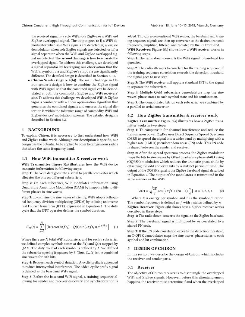
This observation serves as the foundation of our design. Figure 3
shows the combined WiFi and ZigBee signal (the black line) in time
domain. The red line is the original WiFi signal. From Figure 3,
one can tell that WiFi signal’s amplitude changes much slower
than ZigBee signal’s amplitude. Therefore, it is possible to design a
1ZigBee protocol uses Direct Sequence Spread Spectrum (DSSS) technique, in which, a
chip is the smallest unit of a rectangular pulse. Similar to WiFi’s symbol rate, ZigBee’s
chip rate reveals the signal varying speed.
0 200 400 600 800 1000
Time (sample)
-1
0
1
No
rma
lize
d A
mp
litu
de WiFi Signal WiFi ZigBee combined Signal
Figure 3: Combined WiFi and ZigBee Signals
WiFiDevice
ZigBeeDevice
Chiron Receiver
WiFi &
ZigBee Signals Detector
WiFi Demodulator
ZigBee Demodulator
Signals Separator
ZigBee Data
WiFi DataOverlapped
Signals
Sole WiFi
Sole ZigBee
RF
Fron
t-end
(a) Chiron Receiver
WiFiDevice
ZigBeeDevice
Chiron Sender
WiFi Demodulator
ZigBee Demodulator
WiFi & ZigBee Signals Combiner
ZigBee Data
WiFi Data Overlapped
Signals
Sole WiFi
Sole ZigBee
RF Front-end
(b) Chiron Sender
Figure 4: System Architecture
gateway that can send (or receive) the combined WiFi and ZigBee
signal which contains both WiFi data and ZigBee data to (or from)
commodity WiFi and ZigBee devices. By doing this, the spectrum
utilization and throughput can be significantly increased.
3 DESIGN OVERVIEW AND CHALLENGESBased on our observation, the design goal of Chiron is to maximize
the spectrum utilization when the gateway receives (or transmits)
data from (to) commodity WiFi and ZigBee devices. Figure 4 shows
Chiron’s system architecture. For clarity purpose, we divide the
whole system into two parts: i) Chiron Receiver and ii) Chiron
Sender.
• Chiron Receiver (Figure 4(a)): There are two main chal-
lenges in Chiron receiver’s design. The first challenge is
how to incorporate different traffic patterns of wireless traf-
fic generated by commodity WiFi and ZigBee devices at the
gateway. To address this challenge, we design a customized
WiFi & ZigBee signals detector, which can detect whether
Chiron: Concurrent High Throughput Communication for IoT Devices MobiSys ’18, June 10–15, 2018, Munich, Germany
the received signal is a sole WiFi, sole ZigBee or a WiFi and
ZigBee overlapped signal. The output goes to i) a WiFi de-
modulator when sole WiFi signals are detected; ii) a ZigBee
demodulator when sole ZigBee signals are detected; or iii) a
signal separator when the WiFi and ZigBee overlapped sig-
nal are detected. The second challenge is how to separate the
overlapped signal. To address this challenge, we developed
a signal separator by leveraging our observation that the
WiFi’s symbol rate and ZigBee’s chip rate are significantly
different. The detailed design is described in Section 5.1.2.
• Chiron Sender (Figure 4(b)): The main challenge in Ch-
iron sender’s design is how to combine the ZigBee signal
with WiFi signal so that the combined signal can be demod-
ulated at both the commodity ZigBee and WiFi receivers’
side. To address this challenge, we developed WiFi & ZigBee
Signals combiner with a linear optimization algorithm that
generates the combined signals and ensures the signal dis-
tortion is within the tolerance range of commodity WiFi and
ZigBee devices’ modulation schemes. The detailed design is
described in Section 5.2.
4 BACKGROUNDTo explain Chiron, it is necessary to first understand how WiFi
and ZigBee radios work. Although our description is specific, our
design has the potential to be applied to other heterogeneous radios
that share the same frequency band.
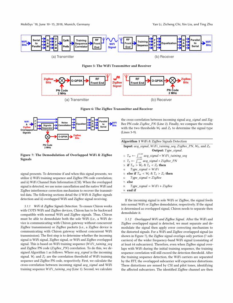
4.1 HowWiFi transmitter & receiver workWiFi Transmitter: Figure 5(a) illustrates how the WiFi device
transmits information in following steps:
Step 1: The WiFi data goes into a serial to parallel converter which
allocates the bits on different subcarriers.
Step 2: On each subcarrier, WiFi modulates information using
Quadrature Amplitude Modulation (QAM) by mapping bits to dif-
ferent phases in sine waves.
Step 3: To combine the sine waves efficiently, WiFi adopts orthogo-
nal frequency-division multiplexing (OFDM) by utilizing an inverse
fast Fourier transform (IFFT), expressed in Equation 1. The duty
cycle that the IFFT operates defines the symbol duration.
Cm (t) =N∑n=0
[(I (t) cos(2π f t1) −Q(t) sin(2π f t1)) e2π jkn
](1)
Where there are N total WiFi subcarriers, and for each n subcarrier,
we defined complex symbols states at the I (t) and Q(t) mapped by
QAM. The duty cycle of each symbol is defined by f . We defined
the subcarrier spacing frequency by k . Thus,Cm (t) is the combined
sine waves formth bits.
Step 4: Between each symbol duration, A cyclic prefix is appended
to reduce intersymbol interference. The added cyclic prefix signal
is defined as the baseband WiFi signal.
Step 5: Before the baseband WiFi signal, a training sequence al-
lowing for sender and receiver discovery and synchronization is
added. Thus, in a conventional WiFi sender, the baseband and train-
ing sequence signals are then up-converter to the desired transmit
frequency, amplified, filtered, and radiated by the RF front-end.
WiFi Receiver: Figure 5(b) shows how a WiFi receiver works in
following steps:
Step 1: The radio down-converts the WiFi signal to baseband fre-
quencies.
Step 2: The radio attempts to correlate for the training sequence. If
the training sequence correlation exceeds the detection threshold,
the signal goes to next step.
Step 3: The WiFi receiver will apply a standard FFT to the signal
to separate the subcarriers.
Step 4: Multiple QAM subcarriers demodulators map the sine
waves’ phase states to each symbol state and bit combination.
Step 5: The demodulated bits on each subcarrier are combined by
a parallel to serial convertor.
4.2 How ZigBee transmitter & receiver workZigBee Transmitter: Figure 6(a) illustrates how a ZigBee trans-
mitter works in two steps:
Step 1: To compensate for channel interference and reduce the
transmission power, ZigBee uses Direct Sequence Spread Spectrum
(DSSS) to spread the signal into a wider band by multiplying with a
higher rate (2 MHz) pseudorandom noise (PN) code. This PN code
is shared between the sender and receiver.
Step 2: After the spread spectrum process, the ZigBee modulator
maps the bits to sine waves by Offset quadrature phase-shift keying
(OQPSK) modulation which reduces the dramatic phase shifts by
offsetting the odd and even bits by a distinct period of time. The
output of the OQPSK signal is the ZigBee baseband signal described
in Equation 2. The output of the modulators is transmitted in the
same manner as the WiFi.
Z (t) =√
2E
Tcos
(2π f t + (2n − 1) π
4
),n = 1, 2, 3, 4 (2)
Where E is energy per symbol, and T is the symbol duration.
The symbol frequency is defined as f with 4 states defined by n.ZigBee Receiver: Figure 6(b) shows how a ZigBee receiver works
described in three steps:
Step 1: The radio down-converts the signal to the ZigBee baseband.Step 2: The baseband signal is multiplied by or correlated to a
shared PN code.
Step 3: If the PN code correlation exceeds the detection threshold,
an O-QPSK demodulator maps the sine waves’ phase states to each
symbol and bit combination.
5 DESIGN OF CHIRONIn this section, we describe the design of Chiron, which includes
the receiver and sender parts.
5.1 ReceiverThe objective of Chiron receiver is to disentangle the overlapped
WiFi and ZigBee signals. However, before this disentanglement
happens, the receiver must determine if and when the overlapped
MobiSys ’18, June 10–15, 2018, Munich, Germany Yan Li, Zicheng Chi, Xin Liu, and Ting Zhu
Serial to
Parallel
WiFiBits
Q A M
Cyclic
Prefix
Training Sequence
O F DM
Training Sequence Correlator
F FT
EqualizationWiFiSignal
WiFiBits
Q A M
RF Front End
Parallel to
Serial
(a) Transmitter (b) Receiver
RF Front End
Figure 5: The WiFi Transmitter and Receiver
ZigBeeBits O-QPSK ZigBee
SignalPN Code
2 MHz
O-QPSK
PN Code 2 MHz
ZigBeeBits
(a) Transmitter (b) Receiver
RF Front End
RF Front End
Figure 6: The ZigBee Transmitter and Receiver
Signals Separator
ZigBeeBitsO-QPSK
Parallel to
Serial
WiFi&
ZigBeeOverlapped
Signals
Q A M
F FT
PN Code 2 MHz
Noise Cancellation Equalizer WiFi
Bits
Figure 7: The Demodulation of Overlapped WiFi & ZigBeeSignals
signal presents. To determine if and when this signal presents, we
utilize i) WiFi training sequence and ZigBee PN code correlation;
and ii) WiFi Channel State Information (CSI). When the overlapped
signal is detected, we use noise cancellation and the nativeWiFi and
ZigBee interference correction mechanism to recover the transmit-
ted data. The following sections detail the i) WiFi & ZigBee signals
detection and ii) overlapped WiFi and ZigBee signal receiving.
5.1.1 WiFi & ZigBee Signals Detection. To ensure Chiron works
with COTS WiFi and ZigBee devices, Chiron has to be backward
compatible with normal WiFi and ZigBee signals. Thus, Chiron
must be able to demodulate both the sole WiFi (i.e., a WiFi de-
vice is communicating with Chiron gateway without concurrent
ZigBee transmission) or ZigBee packets (i.e., a ZigBee device is
communicating with Chiron gateway without concurrent WiFi
transmission). The first step is to determine whether the incoming
signal is WiFi signal, ZigBee signal, or WiFi and ZigBee overlapped
signal. This is based on WiFi training sequence (WiFi_taininд_seqand ZigBee PN code (ZiдBee_PN ) correlation. To do this, we de-
signed Algorithm 1 as follows. Where acq_siдnal is the incoming
signal.Wt and Zt are the correlation threshold of WiFi training
sequence and ZigBee PN code, respectively. First, we calculate the
cross-correlation between incoming signal acq_siдnal and WiFi
training sequenceWiFi_taininд_seq (Line 1). Second, we calculate
the cross-correlation between incoming signal acq_siдnal and Zig-
Bee PN code ZiдBee_PN (Line 2). Finally, we compare the results
with the two thresholdsWt and Zt to determine the signal type
(Lines 3-9).
Algorithm 1 WiFi & ZigBee Signals Detection
Input: acq_siдnal ,WiFi_taininд_seq, ZiдBee_PN ,Wt , and Zt .Output: Type_siдnal .
1: Tw ←∫ +∞−∞ acq_siдnal ∗WiFi_taininд_seq
2: Tz ←∫ +∞−∞ acq_siдnal ∗ ZiдBee_PN
3: if Tw >Wt & Tz < Zt then4: Type_siдnal =WiFi5: else if Tw <Wt & Tz > Zt then6: Type_siдnal = ZiдBee7: else8: Type_siдnal =WiFi + ZiдBee9: end if
If the incoming signal is sole WiFi or ZigBee, the signal feeds
into normal WiFi or ZigBee demodulator, respectively. If the signal
is determined as overlapped signal, Chiron needs to separate then
demodulate it.
5.1.2 Overlapped WiFi and ZigBee Signal. After the WiFi and
ZigBee overlapped signal is detected, we must separate and de-
modulate the signal then apply error correcting mechanism to
the distorted signals. For a WiFi and ZigBee overlapped signal (as
shown in Figure 7), the ZigBee signal overlaps only portion (7 sub-
carriers) of the wider frequency-band WiFi signal (consisting of
at least 64 subcarriers). Therefore, even when ZigBee signal over-
laps with WiFi during the initial training sequence, the training
sequence correlation will still exceed the detection threshold. After
the training sequence detection, the WiFi carriers are separated
by the FFT, the overlapped subcarrier will experience distortions.
These distortions are sensed by CSI and pilot tones, identifying
the affected subcarriers. The identified ZigBee channel are then
Chiron: Concurrent High Throughput Communication for IoT Devices MobiSys ’18, June 10–15, 2018, Munich, Germany
down-converted with the WiFi distortions. To recover from the
WiFi distortions, we implemented filters that remove the slower
WiFi subcarriers signals from the faster-changing ZigBee chips. Af-
ter the high-pass filters operating at WiFi subcarriers frequencies,
the ZigBee signal is demodulated using the normal demodulator
(as we mentioned in Section 4.2) which yields the ZigBee symbols
and bits.
As an overview to recover the WiFi bits (shown in Figure 7),
first, from the received WiFi signal, we subtract out portions of
interfering ZigBee signals. Then, we apply an equalization method
on the remaining WiFi signals using a channel sensing technique.
Finally, after the signals are demodulated into bits, we apply an error
correcting code to the bits associated those equalized and denoised
WiFi subcarriers that are overlapped with ZigBee channels. To
recover the distorted WiFi signal, we designed four steps shown
below:
Step 1: ZigBee Signal Removal:Our ZigBee interference removal
functions by removing the higher frequency ZigBee Chips (2 MHz)
and leaving the slower WiFi symbol (250 KHz). This is done by a
bandpass filter that allows theWiFi signals to proceed and suppress-
ing the ZigBee signal. Thus, this filtering process only occurs on
the portion of WiFi subcarriers that are overlapped by the ZigBee
signal.
Step 2: Environmental Noise cancellation:Chironmust correct
phase noise from ZigBee signal filter and environmental noise (such
as human, transmitter, and receiver movements). Because of human
movements and objects that reflect RF signals, theWiFi channel can
experience strong frequency selective fades. Moreover, Chiron’s
concurrent communication also causes distortions within specific
frequency bands. To remove the frequency and phase distortions,
we utilize pilot tones that are sine waves agreed upon by the trans-
mitter and receiver. Therefore, pilot tones estimate the channel
interference, and then Chiron corrects the interference as follows:
First, the receiver measures the received pilot tone sine wave
represented in complex format. Then, the receiver computes the
offset between the agreed upon expected sine wave expressed in
Equation 3. Finally, by computing the correction factor a and b,the receiver applies a correction to all the subcarriers around pilot
tone’s frequency.
a · I (t) cos(2π f t) − b ·Q(t) sin(2π f t) (3)
Where, I (t) and Q(t) represent the complex sine wave of a pilot
tone, and a and b represent interference added to the pilot tones
and the correction factor.
Step 3: WiFi Demodulation: These equalized quadrature signals
are sent to the normal WiFi OFDM demodulation systems and the
original WiFi bits are recovered (as we introduced in Section 4.1).
Step 4: Forward Error Correction: After the WiFi bits are de-
modulated from each WiFi subcarrier, we note that the ZigBee
overlapped subcarriers have a higher bit error rate. Moreover, the
overlapped ZigBee packets also have a higher probability of error.
By appending Forward Error Correcting (FEC) to the data stream
Signal Combiner
DSSSZigBeeBits O-QPSK
Serial to
Parallel
WiFiBits
Q A M
Cyclic
Prefix
O F DM
Training Sequence Correlator
RF Front End
Figure 8: WiFi & ZigBee Signals Combiner
during concurrent communication, we can also increase the proba-
bility of correct reception. Because the corruption in the WiFi bit-
stream can be expected, as ZigBee packets are transmitted within a
fixed frequency band, we can append extra FEC to non-affected bits.
We utilize a fast linear FEC Low-density parity-check code (LDPC)
to be compatible with modern 802.11 standards. By utilizing LDPC’s
sparse parity matrix, Chiron spread the parity information across
the payload frame. To be compatible with commodity devices, we
increased the convolutional coding FEC rate. Additionally, inter-
leaving bits during formation of the FEC increases the likelihood
of packet reception.
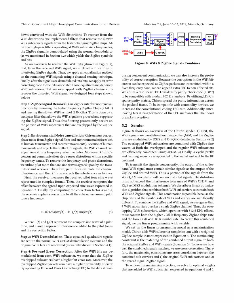
5.2 SenderFigure 8 shows an overview of the Chiron sender. 1) First, the
WiFi signals are parallelized and mapped by QAM, and the ZigBee
bits are modulated by DSSS and O-PQSK (detailed in Section 4). 2)
The overlapped WiFi subcarriers are combined with ZigBee sine
waves. 3) Both the overlapped and the regular WiFi subcarriers
are efficiently combined using OFDM. 4) Finally, a cyclic prefix
and training sequence is appended to the signal and sent to the RF
frontend.
To transmit the signals concurrently, the output of the wider-
band WiFi signal must contain similar signals as the output of the
ZigBee and desired WiFi. Thus, a portion of the signals from the
WiFi QAM modulator will contain distorted signals. The distortion
must not exceed the interference tolerance of WiFi’s OFDM and
ZigBee DSSS modulation schemes. We describe a linear optimiza-
tion algorithm that combines both WiFi subcarriers to contain both
WiFi and ZigBee signals. This combination is possible because the
chip rate and the symbol rate of WiFi and ZigBee are significantly
different. To combine the ZigBee andWiFi signal, we recognize that
7 WiFi subcarriers overlap a single ZigBee channel. Thus, the over-
lapping WiFi subcarriers, which operates with 312.5 KHz offsets,
must contain both the higher 2 MHz frequency ZigBee chips rate
and the lower 250 WiFi KHz symbol rate. To create this combined
signal, we use linear programming with weights.
We set up the linear programming model as a maximization
model. Chiron adds WiFi subcarrier sample instant with a weighted
ZigBee sample instant expressed in Equation 4. The maximizing
constraint is the matching of the combined output signal to both
the original ZigBee and WiFi signals (Equation 5). To measure how
well the combined signals matches, we use cross-correlation. There-
fore, the maximizing constraints are cross-correlation between the
combined sub-carriers and 1) the original WiFi sub-carriers and 2)
the spread signal ZigBee signal.
To achieve thismaximizing objective, we solve for optimalweights
that are added to WiFi subcarrier, expressed in equations 4 and 5.

MobiSys ’18, June 10–15, 2018, Munich, Germany Yan Li, Zicheng Chi, Xin Liu, and Ting Zhu
Chiron
WiFi
ZigBee
(a) Line-of-sight (LoS)
ChironWiFi
ZigBee
(b) None-line-of-sight (NLoS)
WiFi
Chiron
ZigBee
(c) Human in the Middle
Chiron
WearableZigBee
WiFi
(d) Wearable Scenario
Figure 9: Four Experimental Scenarios
Where n to d index of the overlapping WiFi subcarriers, Cm is the
WiFi QAM modulated sine wave, Z (l) is the ZigBee signal, andw is
the weight applied per ZigBee sine wave. The subcarriers are effi-
ciently combined using an IFFT, expressed by the equation eeπ jkt .By solving the weights using a linear optimization technique, we
efficiently combine the WiFi subcarriers described in without hav-
ing to resort to multiple subcarriers down and up conversions and
filtering. The optimal resulting weights represent the higher fre-
quency distortion factors added to each WiFi subcarrier. Thus, this
linear programming results yields an efficiently combined WiFi and
ZigBee signal.
Maxw ∈ R
∑t=0
B∗ (w(t1)) ·C (t1 + n),∑t=0
B∗ (w(t2)) · Z (t2 + n)
(4)
subject to
B(w (t)) =N∑n=0(Cm (t) +w(t) · Z (t)) e2π jkn (5)
In the combined WiFi and ZigBee signal, the ZigBee signal is
typically longer than the WiFi packet. To solve this problem of
different packet length, we leverage nulling out the WiFi signals
expressed in Equation 5. Cm is zero, and the ZigBee signal Z (t)with the weightw is left. Therefore, the overlapping subcarriers are
left with only the ZigBee signals when the ZigBee signal is longer
than the WiFi signal.
6 EXPERIMENTAL EVALUATIONIn this section, we introduce our evaluation of Chiron with different
metrics (i.e., spectrum utilization, throughput, bit error rate and
packet recaption ratio) in four real-world scenarios.
6.1 Experimental SetupWe evaluated our Chiron system in an engineering building, which
has a lot of other WiFi access points, Bluetooth devices, and ZigBee
devices that create interference. We conducted experiments under
four scenarios (shown in Figure 9):
• Line-of-sight (LoS): The Chiron gateway and WiFi/ZigBee de-
vices are in Line-of-sight (shown in Figure 9(a)).
•None-line-of-sight (NLoS):TheChiron gateway andWiFi/ZigBee
devices are placed in different rooms (shown in Figure 9(b)).
• Human in the Middle: During human in the middle scenario,
a person walks in the trajectory shown in the black dashed line
(shown in Figure 9(c)).
•Wearable Scenario: In the wearable scenario, a person carries
a ZigBee device and walks in the trajectory. As described in the
white paper from ZigBee Alliance [3], ZigBee radios are used in
wearable applications, such as chronic disease management, health,
and wellness (shown in Figure 9(d)).
In the LoS, NLoS and human in the middle scenarios, we vary
the communication distance between Chiron gateway and the
WiFi/ZigBee devices. Note that the distance between the WiFi and
ZigBee is fixed because the gateway-to-WiFi’s communication dis-
tance does not impact the communication from the gateway to
ZigBee, and vice versa.
In our experiment, the design of Chiron gateway (described
in Section 5) is implemented on a USRP. We used a commodity
DELL XPS 9550 laptop’s WiFi card and TelosB [2] as the WiFi
and ZigBee devices, respectively, to communicate with Chiron
gateway for evaluation. Since Chiron technique focuses on physical
layer concurrent communications while the application profile may
affect the measured benefit of Chiron, in this evaluation we focused
entirely on the physical layer to explore the advantages of Chiron.
For each data point, we transmitted and received around 5million
bits. The following metrics are used to evaluate the Chiron system:
• Throughput: successfully received bits divide by the transmis-
sion time.
• Bit Error Rate (BER): the number of successfully received bits
divided by the number of transmitted bits.
• Packet Reception Ratio (PRR): the number of successfully
received packets divided by the number of transmitted packets.
• Spectrum Utilization: throughput per second per hertz at the
receiver side.
To compare with Chiron which can conduct concurrent com-
munications between WiFi and ZigBee, we also implemented the
following schemes:
Chiron: Concurrent High Throughput Communication for IoT Devices MobiSys ’18, June 10–15, 2018, Munich, Germany
One Two Three Four
Number of ZigBee Devices
0
5
10
15
Sp
ectr
um
Uti
lizati
on
(bit
/s/H
z)
Traditional Gateway Chiron Gateway
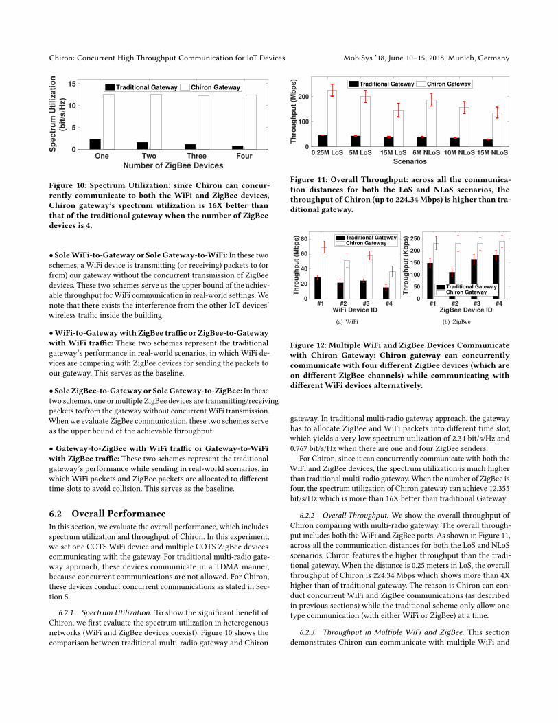
Figure 10: Spectrum Utilization: since Chiron can concur-rently communicate to both the WiFi and ZigBee devices,Chiron gateway’s spectrum utilization is 16X better thanthat of the traditional gateway when the number of ZigBeedevices is 4.
• SoleWiFi-to-Gateway or SoleGateway-to-WiFi: In these twoschemes, a WiFi device is transmitting (or receiving) packets to (or
from) our gateway without the concurrent transmission of ZigBee
devices. These two schemes serve as the upper bound of the achiev-
able throughput for WiFi communication in real-world settings. We
note that there exists the interference from the other IoT devices’
wireless traffic inside the building.
•WiFi-to-Gatewaywith ZigBee traffic or ZigBee-to-Gatewaywith WiFi traffic: These two schemes represent the traditional
gateway’s performance in real-world scenarios, in which WiFi de-
vices are competing with ZigBee devices for sending the packets to
our gateway. This serves as the baseline.
• Sole ZigBee-to-Gatewayor SoleGateway-to-ZigBee: In thesetwo schemes, one ormultiple ZigBee devices are transmitting/receiving
packets to/from the gateway without concurrent WiFi transmission.
When we evaluate ZigBee communication, these two schemes serve
as the upper bound of the achievable throughput.
• Gateway-to-ZigBee with WiFi traffic or Gateway-to-WiFiwith ZigBee traffic: These two schemes represent the traditional
gateway’s performance while sending in real-world scenarios, in
which WiFi packets and ZigBee packets are allocated to different
time slots to avoid collision. This serves as the baseline.
6.2 Overall PerformanceIn this section, we evaluate the overall performance, which includes
spectrum utilization and throughput of Chiron. In this experiment,
we set one COTS WiFi device and multiple COTS ZigBee devices
communicating with the gateway. For traditional multi-radio gate-
way approach, these devices communicate in a TDMA manner,
because concurrent communications are not allowed. For Chiron,
these devices conduct concurrent communications as stated in Sec-
tion 5.
6.2.1 Spectrum Utilization. To show the significant benefit of
Chiron, we first evaluate the spectrum utilization in heterogenous
networks (WiFi and ZigBee devices coexist). Figure 10 shows the
comparison between traditional multi-radio gateway and Chiron
0.25M LoS 5M LoS 15M LoS 6M NLoS 10M NLoS 15M NLoS
Scenarios
0
100
200
Th
rou
gh
pu
t (M
bp
s)
Traditional Gateway Chiron Gateway
Figure 11: Overall Throughput: across all the communica-tion distances for both the LoS and NLoS scenarios, thethroughput of Chiron (up to 224.34 Mbps) is higher than tra-ditional gateway.
#1 #2 #3 #4WiFi Device ID
0
20
40
60
80
Th
rou
gh
pu
t (M
bp
s) Traditional Gateway
Chiron Gateway
(a) WiFi
#1 #2 #3 #4ZigBee Device ID
0
50
100
150
200
250
Th
rou
gh
pu
t (K
bp
s)
Traditional GatewayChiron Gateway
(b) ZigBee
Figure 12: Multiple WiFi and ZigBee Devices Communicatewith Chiron Gateway: Chiron gateway can concurrentlycommunicate with four different ZigBee devices (which areon different ZigBee channels) while communicating withdifferent WiFi devices alternatively.
gateway. In traditional multi-radio gateway approach, the gateway
has to allocate ZigBee and WiFi packets into different time slot,
which yields a very low spectrum utilization of 2.34 bit/s/Hz and
0.767 bit/s/Hz when there are one and four ZigBee senders.
For Chiron, since it can concurrently communicate with both the
WiFi and ZigBee devices, the spectrum utilization is much higher
than traditional multi-radio gateway.When the number of ZigBee is
four, the spectrum utilization of Chiron gateway can achieve 12.355
bit/s/Hz which is more than 16X better than traditional Gateway.
6.2.2 Overall Throughput. We show the overall throughput of
Chiron comparing with multi-radio gateway. The overall through-
put includes both the WiFi and ZigBee parts. As shown in Figure 11,
across all the communication distances for both the LoS and NLoS
scenarios, Chiron features the higher throughput than the tradi-
tional gateway. When the distance is 0.25 meters in LoS, the overall
throughput of Chiron is 224.34 Mbps which shows more than 4X
higher than of traditional gateway. The reason is Chiron can con-
duct concurrent WiFi and ZigBee communications (as described
in previous sections) while the traditional scheme only allow one
type communication (with either WiFi or ZigBee) at a time.
6.2.3 Throughput in Multiple WiFi and ZigBee. This sectiondemonstrates Chiron can communicate with multiple WiFi and
MobiSys ’18, June 10–15, 2018, Munich, Germany Yan Li, Zicheng Chi, Xin Liu, and Ting Zhu
0.25M 5M 15MDistance
0
50
100
150
200
250
Th
rou
gh
pu
t (K
bp
s)
Sole ZigBee-to-GatewayZigBee-to-Gateway w/ WiFiChiron ZigBee-to-Gateway
(a) One ZigBee
0.25M 5M 15MDistance
0
500
1000
1500
2000
Th
rou
gh
pu
t (K
bp
s)
Sole ZigBee-to-GatewayZigBee-to-Gateway w/ WiFiChiron ZigBee-to-Gateway
(b) Four ZigBee
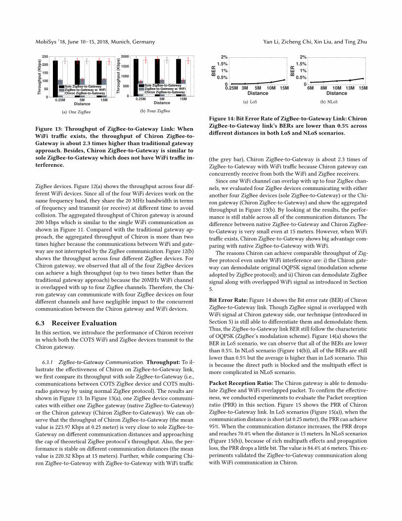
Figure 13: Throughput of ZigBee-to-Gateway Link: WhenWiFi traffic exists, the throughput of Chiron ZigBee-to-Gateway is about 2.3 times higher than traditional gatewayapproach. Besides, Chiron ZigBee-to-Gateway is similar tosole ZigBee-to-Gateway which does not haveWiFi traffic in-terference.
ZigBee devices. Figure 12(a) shows the throughput across four dif-
ferent WiFi devices. Since all of the four WiFi devices work on the
same frequency band, they share the 20 MHz bandwidth in terms
of frequency and transmit (or receive) at different time to avoid
collision. The aggregated throughput of Chiron gateway is around
200 Mbps which is similar to the single WiFi communication as
shown in Figure 11. Compared with the traditional gateway ap-
proach, the aggregated throughput of Chiron is more than two
times higher because the communications between WiFi and gate-
way are not interrupted by the ZigBee communication. Figure 12(b)
shows the throughput across four different ZigBee devices. For
Chiron gateway, we observed that all of the four ZigBee devices
can achieve a high throughput (up to two times better than the
traditional gateway approach) because the 20MHz WiFi channel
is overlapped with up to four ZigBee channels. Therefore, the Chi-
ron gateway can communicate with four ZigBee devices on four
different channels and have negligible impact to the concurrent
communication between the Chiron gateway and WiFi devices.
6.3 Receiver EvaluationIn this section, we introduce the performance of Chiron receiver
in which both the COTS WiFi and ZigBee devices transmit to the
Chiron gateway.
6.3.1 ZigBee-to-Gateway Communication. Throughput: To il-
lustrate the effectiveness of Chiron on ZigBee-to-Gateway link,
we first compare its throughput with sole ZigBee-to-Gateway (i.e.,
communications between COTS ZigBee device and COTS multi-
radio gateway by using normal ZigBee protocol). The results are
shown in Figure 13. In Figure 13(a), one ZigBee device communi-
cates with either one ZigBee gateway (native ZigBee-to-Gateway)
or the Chiron gateway (Chiron ZigBee-to-Gateway). We can ob-
serve that the throughput of Chiron ZigBee-to-Gateway (the mean
value is 223.97 Kbps at 0.25 meter) is very close to sole ZigBee-to-
Gateway on different communication distances and approaching
the cap of theoretical ZigBee protocol’s throughput. Also, the per-
formance is stable on different communication distances (the mean
value is 220.32 Kbps at 15 meters). Further, while comparing Chi-
ron ZigBee-to-Gateway with ZigBee-to-Gateway with WiFi traffic
0.25M 3M 5M 10M 15M
Distance
0
0.5%
1%
1.5%
2%
BE
R
(a) LoS
6M 8M 10M 13M 15M
Distance
0
0.5%
1%
1.5%
2%
BE
R
(b) NLoS
Figure 14: Bit Error Rate of ZigBee-to-Gateway Link: ChironZigBee-to-Gateway link’s BERs are lower than 0.5% acrossdifferent distances in both LoS and NLoS scenarios.
(the grey bar), Chiron ZigBee-to-Gateway is about 2.3 times of
ZigBee-to-Gateway with WiFi traffic because Chiron gateway can
concurrently receive from both the WiFi and ZigBee receivers.
Since one WiFi channel can overlap with up to four ZigBee chan-
nels, we evaluated four ZigBee devices communicating with either
another four ZigBee devices (sole ZigBee-to-Gateway) or the Chi-
ron gateway (Chiron ZigBee-to-Gateway) and show the aggregated
throughput in Figure 13(b). By looking at the results, the perfor-
mance is still stable across all of the communication distances. The
difference between native ZigBee-to-Gateway and Chiron ZigBee-
to-Gateway is very small even at 15 meters. However, when WiFi
traffic exists, Chiron ZigBee-to-Gateway shows big advantage com-
paring with native ZigBee-to-Gateway with WiFi.
The reasons Chiron can achieve comparable throughput of Zig-
Bee protocol even under WiFi interference are: i) the Chiron gate-
way can demodulate original OQPSK signal (modulation scheme
adopted by ZigBee protocol); and ii) Chiron can demodulate ZigBee
signal along with overlapped WiFi signal as introduced in Section
5.
Bit Error Rate: Figure 14 shows the Bit error rate (BER) of ChironZigBee-to-Gateway link. Though ZigBee signal is overlapped with
WiFi signal at Chiron gateway side, our technique (introduced in
Section 5) is still able to differentiate them and demodulate them.
Thus, the ZigBee-to-Gateway link BER still follow the characteristic
of OQPSK (ZigBee’s modulation scheme). Figure 14(a) shows the
BER in LoS scenario, we can observe that all of the BERs are lower
than 0.5%. In NLoS scenario (Figure 14(b)), all of the BERs are still
lower than 0.5% but the average is higher than in LoS scenario. This
is because the direct path is blocked and the multipath effect is
more complicated in NLoS scenario.
Packet Reception Ratio: The Chiron gateway is able to demodu-
late ZigBee and WiFi overlapped packet. To confirm the effective-
ness, we conducted experiments to evaluate the Packet reception
ratio (PRR) in this section. Figure 15 shows the PRR of Chiron
ZigBee-to-Gateway link. In LoS scenarios (Figure 15(a)), when the
communication distance is short (at 0.25meter), the PRR can achieve
95%. When the communication distance increases, the PRR drops
and reaches 70.4% when the distance is 15 meters. In NLoS scenarios
(Figure 15(b)), because of rich multipath effects and propagation
loss, the PRR drops a little bit. The value is 84.4% at 6 meters. This ex-
periments validated the ZigBee-to-Gateway communication along
with WiFi communication in Chiron.

Chiron: Concurrent High Throughput Communication for IoT Devices MobiSys ’18, June 10–15, 2018, Munich, Germany
0.25M 3M 5M 10M 15M
Distance
0
50
100
PR
R (
%)
(a) LoS
6M 8M 10M 13M 15M
Distance
0
50
100
PR
R (
%)
(b) NLoS
Figure 15: Packet Reception Ratio of ZigBee-to-GatewayLink: Chiron ZigBee-to-Gateway link achieve an up to 95%PRR, evenwhen the distance increases to 15meters, the PPRcan still reach 70.4%.
0.25M 5M 15MDistance
0
50
100
150
200
250
Th
rou
gh
pu
t (M
bp
s)
Sole WiFi-to-GatewayWiFi-to-Gateway w/ 1 ZigBeeWiFi-to-Gateway w/ 4 ZigBee
Chiron WiFi-to-Gateway w/ 1 ZigBeeChiron WiFi-to-Gateway w/ 4 ZigBee
Figure 16: Throughput of WiFi-to-Gateway Link: Chironshows similar throughput to sole WiFi-to-Gateway but al-most 4 times of traditional gateway approachwhen four Zig-Bee devices exist.
6.3.2 WiFi-to-Gateway Communication. In this section, we eval-
uate the WiFi-to-Gateway link of Chiron. To do this, we first com-
pare the performance of sole WiFi-to-Gateway (i.e., a WiFi device
communicates with a COTS multi-radio gateway without ZigBee
traffic) with Chiron WiFi-to-Gateway (i.e., concurrent transmission
with ZigBee-to-Gateway link). We conducted the experiments with
either one ZigBee device or four ZigBee devices because one 20
MHz WiFi channel can overlap with up to four ZigBee channels.
The results are shown in Figure 16, we observe that the throughput
of ChironWiFi-to-Gateway can achieve similar level of soleWiFi-to-
Gateway. When the distance is close (i.e., at 0.25 meter LoS), Chiron
WiFi-to-Gateway with one ZigBee and four ZigBee only show 1.4%
and 4% difference comparing with native WiFi-to-Gateway, respec-
tively. When the distance is long, the difference increases because
at the gateway side, Chiron encounters interference from either
one or four ZigBee devices. However, by resolving the interference
(as stated in Section 5), the Chiron WiFi-to-Gateway throughput
with one ZigBee and four ZigBee are only 7.3% and 15% lower than
native WiFi-to-Gateway, respectively, at 15 meters.
Then, we compare the throughput while ZigBee traffic exists. At
0.25 meter, Chiron WiFi-to-Gateway is 1.55X and 3.94X times high
the normal WiFi-to-Gateway while one or 4 ZigBee devices are
communicating with the gateway, respectively. At 15 meters, we
also observe similar increases. The reason is that different normal
0.5M 10M 20M
Distance
0
50
100
150
200
250
Th
rou
gh
pu
t (K
bp
s)
(a) Human in the Middle
Away Towards Pocket Wrist
Scenarios
0
50
100
150
200
250
Th
rou
gh
pu
t (K
bp
s)
(b) Wearable Scenarios
Figure 17: ZigBee-to-Gateway Throughput inMobile Scenar-ios: The performance is stable in different mobile scenarios.
multi-radio gateway, Chiron gateway is able to disentangle and
demodulate WiFi and ZigBee signals concurrently.
6.3.3 Mobile Scenarios. To extensively evaluate the robustness
of Chiron, we conducted an experiments with a designated person
walking in the middle of sender and receiver (as shown in Fig-
ure 9(c)). Moreover, to evaluate the wearable applications (such as
health and wellness monitoring [3]), we also asked the participant
wearing the ZigBee device (in pocket or on wrist) and performing
daily activities (shown in Figure 9(d)).
ZigBee-to-Gateway: Figure 17(a) shows the ZigBee-to-Gatewaylink throughput with humanwalking in the middle. The throughput
is relative stable because the native ZigBee modulation scheme is
well adopted in Chiron that the OQPSK-DSSS scheme is robust to
environment noise. Comparing with direct LoS scenario (Figure
13(a)), the performance only drops 2% when the communication
distance is short. When the communication distance increases to
20 meters, the throughput drops 6.4%.
Figure 17(b) shows four wearable scenarios: i) person walks away
from the Chiron gateway with ZigBee sender in pocket; ii) person
walks towards from the Chiron gateway with ZigBee sender in
pocket; iii) person walks around the meeting room with ZigBee
sender in pocket; and iv) person walks around the meeting room
with ZigBee attached to the wrist. We can observe the fluctuation
across the four wearable scenarios. However, overall, the perfor-
mance is stable. The lowest throughput still can achieve 190 Kbps
when the person walks around the meeting room with ZigBee
sender in pocket.
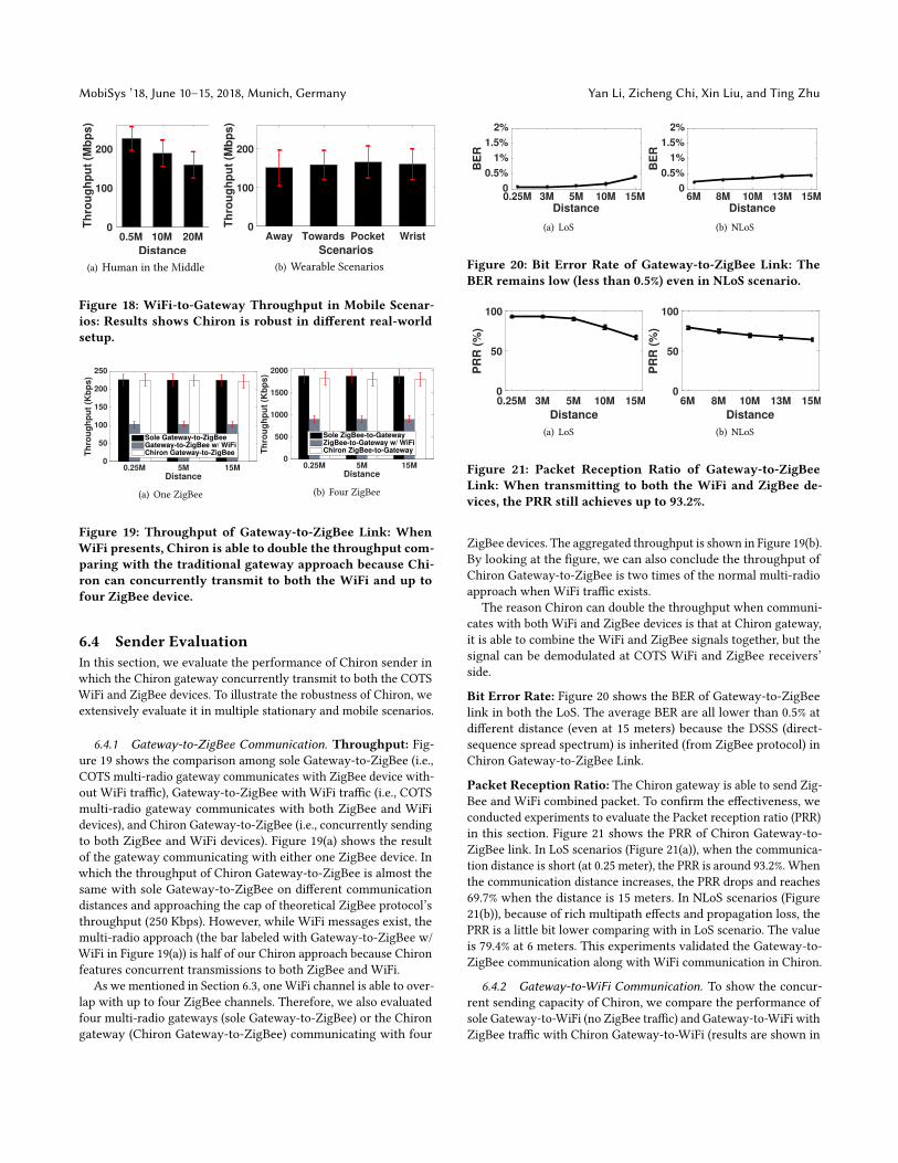
WiFi-to-Gateway: Figure 18 shows theWiFi-to-Gateway link through-
put. In human in the middle (Figure 18(a)), the WiFi-to-Gateway
link maintains up to 226.2 Mbps. However, different from ZigBee-to-
Gateway link, the performance drops relatively quickly because the
sophisticated modulation scheme (which adopts by WiFi protocol)
suffers more degradation in multipath rich environment. In wear-
able scenario (Figure 18(b)), the red error bar (which indicates the
standard deviation) has an average value of 25%, which means the
WiFi-to-Gateway links fluctuates due to the advanced modulation
scheme defined by WiFi standard.
MobiSys ’18, June 10–15, 2018, Munich, Germany Yan Li, Zicheng Chi, Xin Liu, and Ting Zhu
0.5M 10M 20M
Distance
0
100
200
Th
rou
gh
pu
t (M
bp
s)
(a) Human in the Middle
Away Towards Pocket Wrist
Scenarios
0
100
200
Th
rou
gh
pu
t (M
bp
s)
(b) Wearable Scenarios
Figure 18: WiFi-to-Gateway Throughput in Mobile Scenar-ios: Results shows Chiron is robust in different real-worldsetup.
0.25M 5M 15MDistance
0
50
100
150
200
250
Th
rou
gh
pu
t (K
bp
s)
Sole Gateway-to-ZigBeeGateway-to-ZigBee w/ WiFiChiron Gateway-to-ZigBee
(a) One ZigBee
0.25M 5M 15MDistance
0
500
1000
1500
2000
Th
rou
gh
pu
t (K
bp
s)
Sole ZigBee-to-GatewayZigBee-to-Gateway w/ WiFiChiron ZigBee-to-Gateway
(b) Four ZigBee
Figure 19: Throughput of Gateway-to-ZigBee Link: WhenWiFi presents, Chiron is able to double the throughput com-paring with the traditional gateway approach because Chi-ron can concurrently transmit to both the WiFi and up tofour ZigBee device.
6.4 Sender EvaluationIn this section, we evaluate the performance of Chiron sender in
which the Chiron gateway concurrently transmit to both the COTS
WiFi and ZigBee devices. To illustrate the robustness of Chiron, we
extensively evaluate it in multiple stationary and mobile scenarios.
6.4.1 Gateway-to-ZigBee Communication. Throughput: Fig-ure 19 shows the comparison among sole Gateway-to-ZigBee (i.e.,
COTS multi-radio gateway communicates with ZigBee device with-
out WiFi traffic), Gateway-to-ZigBee with WiFi traffic (i.e., COTS
multi-radio gateway communicates with both ZigBee and WiFi
devices), and Chiron Gateway-to-ZigBee (i.e., concurrently sending
to both ZigBee and WiFi devices). Figure 19(a) shows the result
of the gateway communicating with either one ZigBee device. In
which the throughput of Chiron Gateway-to-ZigBee is almost the
same with sole Gateway-to-ZigBee on different communication
distances and approaching the cap of theoretical ZigBee protocol’s
throughput (250 Kbps). However, while WiFi messages exist, the
multi-radio approach (the bar labeled with Gateway-to-ZigBee w/
WiFi in Figure 19(a)) is half of our Chiron approach because Chiron
features concurrent transmissions to both ZigBee and WiFi.
As we mentioned in Section 6.3, one WiFi channel is able to over-
lap with up to four ZigBee channels. Therefore, we also evaluated
four multi-radio gateways (sole Gateway-to-ZigBee) or the Chiron
gateway (Chiron Gateway-to-ZigBee) communicating with four
0.25M 3M 5M 10M 15M
Distance
0
0.5%
1%
1.5%
2%
BE
R
(a) LoS
6M 8M 10M 13M 15M
Distance
0
0.5%
1%
1.5%
2%
BE
R
(b) NLoS
Figure 20: Bit Error Rate of Gateway-to-ZigBee Link: TheBER remains low (less than 0.5%) even in NLoS scenario.
0.25M 3M 5M 10M 15M
Distance
0
50
100
PR
R (
%)
(a) LoS
6M 8M 10M 13M 15M
Distance
0
50
100
PR
R (
%)
(b) NLoS
Figure 21: Packet Reception Ratio of Gateway-to-ZigBeeLink: When transmitting to both the WiFi and ZigBee de-vices, the PRR still achieves up to 93.2%.
ZigBee devices. The aggregated throughput is shown in Figure 19(b).
By looking at the figure, we can also conclude the throughput of
Chiron Gateway-to-ZigBee is two times of the normal multi-radio
approach when WiFi traffic exists.
The reason Chiron can double the throughput when communi-
cates with both WiFi and ZigBee devices is that at Chiron gateway,
it is able to combine the WiFi and ZigBee signals together, but the
signal can be demodulated at COTS WiFi and ZigBee receivers’
side.
Bit Error Rate: Figure 20 shows the BER of Gateway-to-ZigBee
link in both the LoS. The average BER are all lower than 0.5% at
different distance (even at 15 meters) because the DSSS (direct-
sequence spread spectrum) is inherited (from ZigBee protocol) in
Chiron Gateway-to-ZigBee Link.
Packet Reception Ratio: The Chiron gateway is able to send Zig-
Bee and WiFi combined packet. To confirm the effectiveness, we
conducted experiments to evaluate the Packet reception ratio (PRR)
in this section. Figure 21 shows the PRR of Chiron Gateway-to-
ZigBee link. In LoS scenarios (Figure 21(a)), when the communica-
tion distance is short (at 0.25 meter), the PRR is around 93.2%. When
the communication distance increases, the PRR drops and reaches
69.7% when the distance is 15 meters. In NLoS scenarios (Figure
21(b)), because of rich multipath effects and propagation loss, the
PRR is a little bit lower comparing with in LoS scenario. The value
is 79.4% at 6 meters. This experiments validated the Gateway-to-
ZigBee communication along with WiFi communication in Chiron.
6.4.2 Gateway-to-WiFi Communication. To show the concur-
rent sending capacity of Chiron, we compare the performance of
sole Gateway-to-WiFi (no ZigBee traffic) and Gateway-to-WiFi with
ZigBee traffic with Chiron Gateway-to-WiFi (results are shown in

Chiron: Concurrent High Throughput Communication for IoT Devices MobiSys ’18, June 10–15, 2018, Munich, Germany
0.25M 5M 15M
Distance
0
100
200
300
Th
rou
gh
pu
t (M
bp
s)
Sole Gateway-to-WiFi
Gateway-to-WiFi w/ 1 ZigBee
Gateway-to-WiFi w/ 4 ZigBee
Chiron Gateway-to-WiFi w/ 1 ZigBee
Chiron Gateway-to-WiFi w/ 4 ZigBee
Figure 22: Throughput of Gateway-to-WiFi Link: Chironshows about 5 times of the traditional gateway approachwhen transmitting to four ZigBee devices concurrently.
0.5M 10M 20M
Distance
0
50
100
150
200
250
Th
rou
gh
pu
t (K
bp
s)
(a) Human in the Middle
Away Towards Pocket Wrist
Scenarios
0
50
100
150
200
250
Th
rou
gh
pu
t (K
bp
s)
(b) Wearable Scenarios
Figure 23: Gateway-to-ZigBee Throughput inMobile Scenar-ios: The throughput is very close to that in LoS scenario,which validate the robustness of Chiron.
Figure 22). When there is no ZigBee message to send we observe
that the throughput of Chiron Gateway-to-WiFi can achieve similar
level of sole Gateway-to-WiFi. If the gateway has ZigBee message,
our Chiron design shows huge benefit. When the gateway needs to
communicate with one ZigBee, Chiron Gateway-to-WiFi shows two
times better performance comparing with the normal multi-radio
gateway approach. Furthermore, when communicating with four
ZigBee devices, Chiron shows almost four times better performance
comparing with the normal multi-radio gateway approach. The
reason is that Chiron can better utilizes the spectrum to embed
ZigBee signal into WiFi signal. Since one 20 MHz WiFi channel is
overlapped with up to four ZigBee channels, the Chiron gateway
is able to communicate with four ZigBee receivers along with one
WiFi receiver.
6.4.3 Mobile Scenarios. To fit Chiron in mobility applications,
we also evaluated it in human in the middle (as shown in Figure
9(c)) and wearable scenarios (as shown in Figure 9(d)).
Gateway-to-ZigBee: Figure 23(a) shows the Gateway-to-ZigBeelink throughput with humanwalking in the middle. The throughput
is relative stable because the native ZigBee modulation scheme is
well adopted in Chiron that the OQPSK-DSSS scheme is robust to
environment noise. Comparing with direct LoS scenario (Figure
19(a)), the performance only drops 3% when the communication
distance is short. When the communication distance increases to
20 meters, the throughput drops 7.6%.
0.5M 10M 20M
Distance
0
100
200
Th
rou
gh
pu
t (M
bp
s)
(a) Human in the Middle
Away Towards Pocket Wrist
Scenarios
0
100
200
Th
rou
gh
pu
t (M
bp
s)
(b) Wearable Scenarios
Figure 24: Gateway-to-WiFi Throughput in Mobile Scenar-ios: In human in the middle scenario, the Gateway-to-WiFi link’s throughput can be up to 245.07 Mbps. In dif-ferent wearable scenarios, our approach maintains similarthroughput. This demonstrates that our design can supportdifferent types wearable applications.
Figure 23(b) shows four wearable scenarios: i) person walks away
from the Chiron gateway with ZigBee sender in pocket; ii) person
walks towards from the Chiron gateway with ZigBee sender in
pocket; iii) person walks around the meeting room with ZigBee
sender in pocket; and iv) person walks around the meeting room
with ZigBee attached to the wrist. We can observe the fluctuation
across the four wearable scenarios. However, overall, the perfor-
mance is stable. The lowest throughput still can achieve 188.07
Kbps when the person walks around the meeting room with ZigBee
sender in pocket.
Gateway-to-WiFi: Figure 24 shows the throughput of the Gateway-to-WiFi link. In human in the middle (see Figure 24(a)) scenario, the
Gateway-to-WiFi link’s throughput can be up to 245.07 Mbps. Even
when the distance increases to 20 meters, its throughput is still
more than 165 Mbps. This indicates that our design is reliable over
a long distance. In different wearable scenarios (see Figure 24(b)),
our approach maintains similar throughput. This demonstrates that
our design can support different types wearable applications.
7 RELATEDWORKSTo improve the performance ofwireless communication, researchers
have proposed various interference mitigate techniques [7, 10, 22,
24, 25, 27, 29] and collision avoidance solutions [19, 20, 26, 28, 29].
To further improve the spectrum utilization, different methods [6,
8, 14, 16, 17, 21, 23, 30, 31, 34, 38] have been proposed. Instead of
improving spectrum utilization within the same protocol (i.e., WiFi
or ZigBee), our work takes a new approach by exploring the possi-
bility of increasing the spectrum utilization when heterogeneous
radios with different protocols are communicating concurrently.
Specifically, our approach enables the bi-directional concurrent
communication of WiFi and ZigBee.
Several cross-technology communication systems [4, 5, 12, 13,
15, 32, 33, 36, 39, 40] have been introduced, to utilize the coexis-
tent features of different wireless technologies within the same
frequency band.
Esense [4] and HoWiES [40] enable WiFi to ZigBee communica-
tion by sensing the packet length of WiFi packets. GSense [39] uses
special preamble to coordinate heterogeneous devices. FreeBee [15]
achieved communication among WiFi, ZigBee and Bluetooth by
modulating periodical beacons. EMF [36], C-MORSE [33], DCTC
MobiSys ’18, June 10–15, 2018, Munich, Germany Yan Li, Zicheng Chi, Xin Liu, and Ting Zhu
[13], and WiZig [12] convey cross-technology data at the packet
level (i.e., packet length or transmission power). This packet level
modulation results a low network performance (i.e., the throughput
is at tens or hundreds of bps level). B2W 2[5] enables BLE to WiFi
transmission by using CSI of WiFi system. WEBee [37] and PMC
[35] use WiFi signal to emulate ZigBee signal at the physical layer.
Although WEBee can achieve relatively high CTC throughput,
its spectrum utilization is extremely low. This is because when
WEBee uses WiFi packets to emulate ZigBee packets, the original
payload in theWiFi packets are changed and cannot be used to send
out the WiFi data. A single WiFi transmission occupies a 20 MHz
channel, while ZigBee receivers only obtain information within a
2MHz-wide ZigBee channel. Since WiFi has more advanced modu-
lation schemes, WiFi can use its 20 MHz channel to transmit WiFi
packets at hundreds of Mb/s. By using WEBee, WiFi can only em-
ulate ZigBee packets at 126 Kbps. Therefore, WEBee’s spectrum
utilization is much lower than original WiFi communication. Simi-
larly, BlueBee [32] also has very low spectrum efficiency, because it
uses high throughput Bluetooth signal to emulate low throughput
ZigBee signal. Moreover, WEBee, PMC, and BlueBee only provide
the communication from one direction (i.e., WiFi or Bluetooth to
ZigBee).
Different from the above approaches, our approach enables the
concurrent communication from both WiFi and ZigBee devices to
the gateway and the reverse direction. By combining or separating
the WiFi and ZigBee signal at the bit level, Chiron is able to achieve
the similar performance as if in sole WiFi to WiFi or ZigBee to
ZigBee communications. Our experimental results demonstrate
that our approach’s spectrum utilization is more than 16 times
higher than traditional approaches.
8 DISCUSSION AND FUTUREWORKIn this section, we discuss the potential opportunities of Chiron.
8.1 Chiron under Different WiFi StandardsWiFi standard includes a variety of generations (from IEEE 802.11 to
IEEE 802.11ah and so on). Since Chiron solves the spectrum waste
problem while WiFi coexists with ZigBee, we only consider the
standard works within 2.4GHz band. As long as the WiFi standard
uses OFDM based modulation scheme, such as IEEE 802.11 g/n/ac,
Chiron is compatible. That is because the OFDM based modulation
scheme chops a wide band (i.e., 20MHz) into small pieces (i.e.,
312.5 KHz), which yields a slow symbol rate as we discovered in the
motivation section. It is possible that Chiron can support the 40MHz
WiFi channel defined by IEEE 802.11n. And more interesting, up
to 8 ZigBee channels are overlapped with a 40 MHz WiFi channel.
This means that by using Chiron technique, the gateway is able
to concurrently communicate with one WiFi device and up to 8
ZigBee devices. In this scenario, the spectrum utilization can be
further improved. We will investigate it in our future work.
Multiple-input and multiple-output (MIMO) technique is intro-
duced to WiFi system since IEEE 802.11n. Basically, the MIMO
technique increases throughput by spacial multiplexing (i.e, using
multiple antennas at both the sender and receiver sides to multiply
the channel capacity). For a MIMO enabled WiFi system (e.g., with
IEEE 802.11n, a WiFi sender with two antennas and a WiFi receiver
with two antennas consist a 2 × 2MIMO system), it is possible to
enable Chiron technique because the Chiron gateway only needs
to transmit one spacial stream to ZigBee device.
8.2 Generality of ChironOur Chiron technique explores the possibility to combine WiFi
and ZigBee signals. Potentially, Chiron technique can be applied
to other wireless communications as long as two communication
protocols: i) work on the overlapped frequency bands; and ii) have
distinct symbol rates. By having these two properties, it is possible
that Chiron can utilize the tolerance of wireless communication to
combine two signals with different modulation schemes. However,
due to the varieties of different modulation schemes, more future
works are needed to investigate different combinations.
8.3 Supports for Upper LayersWith the exponentially increasing number of IoT devices, the tra-
ditional multi-radio gateway (e.g., a gateway equipped with both
WiFi and ZigBee radios) introduces a spectrum utilization bottle-
neck, which is caused by the competition between WiFi and ZigBee
communications (shown in Figure 1 in the introduction section).
Our Chiron technique utilizes the unique properties of WiFi’s and
ZigBee’s physical layers to significantly improve the spectrum uti-
lization. Since Chiron technique does not require any hardware
modification on ZigBee device, the original functionalities at upper
layers should not be affected, but we have not evaluated that. To fur-
ther evaluate whether Chiron technique affects the original upper
layers’ design, we plan to investigate the application profiles such
as ZigBee Home Automation (HA), ZigBee Light Link (LL), and
building automation in the future. We also plan to investigate how
to leverage the Chiron technique for further performance improve-
ments in existing upper layer MAC [41–43], routing [9, 18, 44–46],
and flooding protocols [11, 47, 48].
9 CONCLUSIONWith the exponentially increasing number of IoT devices, there
is a pressing need to more efficiently utilize the spectrum in the
crowded ISM band, especially at the edge (i.e., gateway) of the IoT
network. In this paper, we explore a new direction – concurrent
communication for a gateway to (or from) commodity WiFi and
ZigBee devices. Our extensive experimental results indicate that
Chiron achieves reliable performance under different settings (i.e.,
LoS, NLoS, mobile, and wearable). Chiron’s concurrent WiFi and
ZigBee communication can achieve similar throughput as the sole
WiFi or ZigBee communication.
The design principle of Chiron is generic and has the potential
to be applied to other frequency band that coexists radios with dif-
ferent symbol rates. The design of Chiron fits naturally at the edge
of IoT networks to support commodity WiFi and ZigBee devices.
By simply changing the gateway, the spectrum utilization can be
increased by more than 16 times.
ACKNOWLEDGMENTSThis project is supported by NSF grants CNS-1652669 and CNS-
1539047. We also thank anonymous reviewers and our shepherd
Dr. Ben Greenstein for their valuable comments.
Chiron: Concurrent High Throughput Communication for IoT Devices MobiSys ’18, June 10–15, 2018, Munich, Germany
REFERENCES[1] https://en.wikipedia.org/wiki/IEEE_802.11n-2009.
[2] http://www.memsic.com/userfiles/files/DataSheets/WSN/telosb_datasheet.pdf.
[3] http://www.zigbee.org/zigbee-for-developers/applicationstandards/
zigbee-health-care/.
[4] Chebrolu, K., and Dhekne, A. Esense: Communication through energy sensing.
In MobiCom, 2009.[5] Chi, Z., Li, Y., Sun, H., Yao, Y., Lu, Z., and Zhu, T. B2w2: N-way parallel
communication for iot devices. In Sensys, 2016.[6] Chintalapudi, K., Radunovic, B., Balan, V., Buettener, M., Yerramalli, S.,
Navda, V., and Ramjee, R. Wifi-nc: Wifi over narrow channels. In NSDI, 2012.[7] Das, S. M., Koutsonikolas, D., Hu, Y. C., and Peroulis, D. Characterizing
multi-way interference in wireless mesh networks. In WiNTECH, 2016.[8] Deek, L., Garcia-Villegas, E., Belding, E., Lee, S.-J., and Almeroth, K. The
impact of channel bonding on 802.11n network management. In CoNEXT, 2011.[9] Gu, Y., Zhu, T., and He, T. Esc: Energy synchronized communication in sus-
tainable sensor networks. In 2009 17th IEEE International Conference on NetworkProtocols (Oct 2009), pp. 52–62.
[10] Gummadi, R., Wetherall, D., Greenstein, B., and Seshan, S. Understanding
and mitigating the impact of rf interference on 802.11 networks. In SIGCOMM,2007.
[11] Guo, S., Kim, S. M., Zhu, T., Gu, Y., and He, T. Correlated flooding in low-duty-
cycle wireless sensor networks. In 2011 19th IEEE International Conference onNetwork Protocols (Oct 2011), pp. 383–392.
[12] Guo, X., Zheng, X., and He, Y. Wizig: Cross-technology energy communication
over a noisy channel. In IEEE INFOCOM 2017 - IEEE Conference on ComputerCommunications (May 2017), pp. 1–9.
[13] Jiang, W., Yin, Z., Kim, S. M., and He, T. Transparent cross-technology commu-
nication over data traffic. In IEEE INFOCOM 2017 - IEEE Conference on ComputerCommunications (May 2017), pp. 1–9.
[14] Khan, M., Bhartia, A., Qiu, L., and Lin, K. C.-J. Smart retransmission and rate
adaptation in wifi. In ICNP, 2015.[15] Kim, S. M., and He, T. Freebee: Cross-technology communication via free side-
channel. In MobiCom 2015.[16] Kumar, S., Cifuentes, D., Gollakota, S., and Katabi, D. Bringing cross-layer
mimo to today’s wireless lans. In SIGCOMM, 2013.[17] Lee, O., Sun, W., Kim, J., Lee, H., Ryu, B., Lee, J., and Choi, S. Chaser: Channel-
aware symbol error reduction for high-performance wifi systems in dynamic
channel environment. In INFOCOM, 2015.[18] Malvankar, A., Yu, M., and Zhu, T. An availability-based link qos routing for
mobile ad hoc networks. In 2006 IEEE Sarnoff Symposium (March 2006), pp. 1–4.
[19] Merz, R., Widmer, J., Le Boudec, J.-Y., and Radunovic, B. A Joint PHY/MAC
Architecture for Low-Radiated Power TH-UWBWireless Ad Hoc Networks. Tech.
rep., 2004.
[20] Nandagopal, T., Kim, T.-E., Gao, X., and Bharghavan, V. Achieving mac layer
fairness in wireless packet networks. In MobiCom, 2010.[21] Panchal, J. S., Yates, R. D., and Buddhikot, M. M. Mobile network resource
sharing options: Performance comparisons. IEEE Transactions on Wireless Com-munications 12, 9 (September 2013), 4470–4482.
[22] Prasad, N., Arslan, M., and Rangarajan, S. Enhanced interference manage-
ment in heterogeneous cellular networks. In ISIT, 2014.[23] Premnath, S. N., Wasden, D., Kasera, S. K., Farhang-Boroujeny, B., and
Patwari, N. Beyond ofdm: Best-effort dynamic spectrum access using filterbank
multicarrier. In COMSNETS, 2012.[24] Sahai, A., Aggarwal, V., Yuksel, M., and Sabharwal, A. Capacity of all nine
models of channel output feedback for the two-user interference channel. IEEETransactions on Information Theory 59, 11 (Nov 2013), 6957–6979.
[25] Salimi, S., Jorswieck, E. A., Skoglund, M., and Papadimitratos, P. Key agree-
ment over an interference channel with noiseless feedback: Achievable region
distributed allocation. In CNS, 2015.[26] Sen, S., Choudhury, R. R., and Nelakuditi, S. Csma/cn: Carrier sense multiple
access with collision notification. IEEE/ACM Trans. Netw. 20, 2 (Apr. 2012), 544–556.
[27] Sen, S., Santhapuri, N., Choudhury, R. R., and Nelakuditi, S. Successive
interference cancellation: Carving out mac layer opportunities. IEEE Transactionson Mobile Computing 12, 2 (Feb 2013), 346–357.
[28] Shi, J., Aryafar, E., Salonidis, T., and Knightly, E. W. Synchronized csma
contention: Model, implementation and evaluation. In INFOCOM, 2009.[29] Singh, N., Gunawardena, D., Proutiere, A., Radunovi, B., Balan, H. V., and
Key, P. Efficient and fair mac for wireless networks with self-interference can-
cellation. In WiOpt, 2011.[30] Sun, L., Sen, S., and Koutsonikolas, D. Bringing mobility-awareness to wlans
using phy layer information. In CoNEXT, 2014.[31] Tan, K., Shen, H., Zhang, J., and Zhang, Y. Enable flexible spectrum access
with spectrum virtualization. In DySpan, 2012.[32] Wenchao Jiang, Roufeng Liu, Zhimeng Yin, SongMin Kim and T. He. Bluebee:
a 10,000x faster cross-technology communication. In SenSys (2017).
[33] Yin, Z., Jiang, W., Kim, S. M., and He, T. C-morse: Cross-technology communi-
cation with transparent morse coding. In IEEE INFOCOM 2017 - IEEE Conferenceon Computer Communications (May 2017), pp. 1–9.
[34] Yun, S., Kim, D., and Qiu, L. Fine-grained spectrum adaptation in wifi networks.
In MobiCom, 2013.[35] Z. Chi, Y. Li, Y. Yao, and T. Zhu. PMC: Parallel Multi-protocol Communication
to Heterogeneous IoT Radios within a Single WiFi Channel. In ICNP (2017).
[36] Z. Chi, Z. Huang, Y. Yao, T. Xie, H. Sun, and T. Zhu. EMF: Embedding Multiple
Flows of Information in Existing Traffic for Concurrent Communication among
Heterogeneous IoT Devices. In INFOCOM (2016).
[37] Z. Li and T. He. Webee: Physical-layer cross-technology communication via
emulation. In MobiCom (2017).
[38] Zhang, J., Shen, H., Tan, K., Chandra, R., Zhang, Y., and Zhang, Q. Frame
retransmissions considered harmful: Improving spectrum efficiency using micro-
acks. In MobiCom, 2012.[39] Zhang, X., and Shin, K. G. Gap sense: Lightweight coordination of heteroge-
neous wireless devices. In INFOCOM, 2013.[40] Zhang, Y., and Li, Q. Howies: A holistic approach to zigbee assisted wifi energy
savings in mobile devices. In INFOCOM, 2013.[41] Zhou, C., and Zhu, T. Highly spatial reusable mac for wireless sensor networks.
In IEEE WiCOM (2007).
[42] Zhou, C., and Zhu, T. A spatial reusable mac protocol for stable wireless sensor
networks. In IEEE WiCOM (2008).
[43] Zhou, C., and Zhu, T. Thorough analysis of mac protocols in wireless sensor
networks. In IEEE WiCOM (2008).
[44] Zhu, T., and Towsley, D. E2r: Energy efficient routing for multi-hop green wire-
less networks. In 2011 IEEE Conference on Computer Communications Workshops(INFOCOM WKSHPS) (April 2011), pp. 265–270.
[45] Zhu, T., and Yu, M. A dynamic secure qos routing protocol for wireless ad hoc
networks. In 2006 IEEE Sarnoff Symposium (March 2006), pp. 1–4.
[46] Zhu, T., and Yu, M. Nis02-4: A secure quality of service routing protocol for
wireless ad hoc networks. In IEEE Globecom 2006 (Nov 2006), pp. 1–6.[47] Zhu, T., Zhong, Z., He, T., and Zhang, Z.-L. Exploring link correlation for
efficient flooding in wireless sensor networks. In Proceedings of the 7th USENIXConference on Networked Systems Design and Implementation (Berkeley, CA, USA,
2010), NSDI’10, USENIX Association, pp. 4–4.
[48] Zhu, T., Zhong, Z., He, T., and Zhang, Z. L. Achieving efficient flooding by
utilizing link correlation in wireless sensor networks. IEEE/ACM Transactions onNetworking 21, 1 (Feb 2013), 121–134.