Embed Size (px)
Citation preview

L.B.Abhang et al. / International Journal of Engineering Science and Technology Vol. 2(4), 2010, 382-393
Chip-Tool Interface Temperature Prediction Model for Turning Process
L.B.ABHANG* and M. HAMEEDULLAH
Mechanical engineering department, Aligarh Muslim University, Aligarh, India
ABSTRACT
In this research work the tool-chip interface temperature is measured experimentally during turning of EN-31 steel alloy with tungsten carbide inserts using a tool-work thermocouple technique. First and second-order mathematical models are developed in terms of machining parameters by using the response surface methodology on the basis of the experimental results. The results are analyzed statistically and graphically. The metal cutting parameters considered are cutting speed, feed rate, depth of cut and tool nose radius. It can be seen from the first order model that the cutting speed, feed rate and depth of cut are the most significantly influencing parameters for the chip-tool interface temperature followed by tool nose radius. Another quadratic model shows the variation of chip-tool interface with major interaction effect between cutting speed and depth of cut (V*D) and second order (quadratic) effect of cutting speed (V2) appears to be highly significant. The results show that increase in cutting speed, feed rate and depth of cut increases the cutting temperature while increasing nose radius reduces the cutting temperature. The suggested models of chip-tool interface temperature adequately map within the range of the cutting conditions considered. Keywords: Metal cutting, Tool-work thermocouple, Response surface methodology, Factorial design, Chip-tool interface temperature.
1. INTRODUCTION Temperature on the chip-tool interface is important parameters in the analysis and control of machining process. Due to the high shear and friction energies dissipated during a machining operation the temperature in the primary and secondary shear zones are usually very high, hence affect the shear deformation and tool wear. In a single point cutting, heat is generated at three different zones i.e. primary shear zone, chip tool interface and the tool work-piece interface as shown in Fig.1. The primary shear zone temperature affects the mechanical properties of the work piece-chip material and temperatures at the tool-chip and tool-work piece interfaces influence tool wear at tool face and flank respectively. Total tool wear rate and crater wear on the rake face are strongly influenced by the temperature at chip-tool interface. Therefore, it is desirable to determine the temperatures of the tool and chip interface to analyze or control the process. To measure the tool temperature at the tool chip interface many experimental methods have been developed over the past century. Since at the interface there is a moving contact between the tool and chip, experimental techniques such as standard pre calibrated thermocouples can not be used to measure the interface temperature.
Fig.1. Heat generated by chip formation.
Much research has been undertaken into measuring the temperatures generated during cutting operations. The main techniques used to evaluate the cutting temperature during machining are tool-chip
ISSN: 0975-5462 382
L.B.Abhang et al. / International Journal of Engineering Science and Technology Vol. 2(4), 2010, 382-393
thermocouple, embedded thermocouple, and thermal radiation method as reported by Barrow [1]. The thermocouple methods are based on the thermocouple principle that states that two contacting materials produce an electromotive force (emf) due to difference in temperatures of cold and hot junctions. The validity of assumptions made and possible sources of errors in different experimental techniques have been out lined by Barrow [1]. Tool-work thermocouple has become a popular tool to be used in temperature measurements during metal cutting. This method is very useful to indicate the effects of the cutting speed, feed rate, depth of cut and the tool parameters on the temperature. In tool-work thermocouple the chip-tool interface forms the hot junction, while the tool end forms the cold junction. The tool and workpiece need to be electrically insulated from the machine tool. This cutting temperature measurement technique is easy to apply for the measurement of chip-tool interface temperature during metal cutting over the entire contact area as reported by Shaw [2]. Based on these measurement using the thermocouple method, Stephenson [3, 4] stated that the average emf is generated a tool- work piece interface. The difficulty of this method is concerned with the necessity for an accurate calibration of the tool and workpiece materials as a thermocouple pair. In order to measure the cutting edge temperature using a thermocouple two different methods can be used to fix the hot junction close to the cutting edge. In the first method, the thermocouple is clamped in a recess, which is ground off the rake face of the tool to locate the hot junction as close as possible to the cutting edge. In the second method, the thermocouple is inserted in a precisely grooved carbide chip breaker, which is clamped mechanically on the tool such that the hot junction is at the same distance as in the first method. Comparing results obtained by the two methods showed that both methods gave the same results [5]. Therefore it was suggested that the second method is better since the recess in the cutting tool would change the temperature distribution along the rake face. In addition the second method is considered easier to implement. In this paper the tool-work thermo couple technique was used to measure the chip-tool interface temperature during machining of EN-31 steel alloy. In 1954 Lower and Shaw’s [6] developed analytical prediction model for the measurement of cutting temperature during machining. They concluded that the cutting temperature is the function of cutting speed and feed rate. θt = V 0.5*t 0.3 (1) Where, θt = Average cutting temperature V = cutting speed t = undeformed chip- thickness or feed rate. The Lowen and Shaw’s method was found to be the best predictor according to Stephenson [4]. Wardeny et al [5] suggested that the temperature distribution in the tool may be obtained by using information about the changes in the hardness and microstructure of the steel tool. It is necessary to calibrate the hardness of the tool against the temperature and time of heating and samples of structural changes at corresponding temperatures. These methods permit measurement of temperatures to an accuracy of ± 25o C within the heat affected region. However, Wright [7] commented that these methods are arduous and difficult to use. Trigger [8] investigated the tool-work interface temperatures using the thermo-couple technique. This work differs from the earlier work in that cemented carbide tools were used in machining steels instead of the HSS tools. Both the elements of tool-work thermocouple comprised of iron base alloys of similar basic lattice structure, a factor which can influence the tendency of the chip to form a built up edge on the tool and consequently cause erratic results. Grzesik [9] measured tool-work interface temperature when machining an AISI 1045 and an AISI 304 with coated tools used a standard K-type of thermocouple inserted in the work piece and reported that the friction on the flank face had a big influence on the heat generated at about 200 m/min cutting speed. Sullivan and Cotterm [10] measured the machined surface temperatures with two thermocouples inserted into the work piece when machining aluminum 6082-T6. The results indicated that an increase in cutting speed resulted in a decrease in cutting forces and machined surface temperatures. This reduction in temperature was attributed to the higher metal removal rate that resulted in more heat being carried away by the chip. Trent et al. [11] suggested that during the machining process, a considerable amount of the machine energy is transferred to heat through plastic deformation of the work-piece surface, the friction of the chip on the tool face and the friction between tool and the work-piece, about 99% of the work done is converted into heat. This results in an increase in the tool and work temperatures. According to Muller-Hummed Panda Lathres [12] the temperature distribution depends on the heat conductivity and specific heat capacity of the tool and the work piece and finally the amount of heat loss based on radiation and convention. The maximum temperature occurs in the contact zone between the chip and the tool. The heat generated in this zone is distributed among the tool, the work piece, the chip and after that to the environment. Heat generated at the shearing plane can make the cutting action easy, but it can flow into the cutting edge and that will negatively affect the tool life by shortening it. S.K. Chaudhary et al. [13] predicted cutting zone temperatures by natural tool work thermocouple technique, when machining EN 24 steel work piece and HSS with 10% cobalt as the cutting tool. The results
ISSN: 0975-5462 383

L.B.Abhang et al. / International Journal of Engineering Science and Technology Vol. 2(4), 2010, 382-393
indicated that an increase in cutting speed and feed rate resulted in an increase in tool wear and cutting zone temperature increases with the increase in the cutting speed. While in the whole range of feed the temperature increases with increase in feed rate. Federi com Aneriro et al [14] investigated the influence of cutting parameters (cutting speed, feed rate and depth of cut) on tool temperature, tool wear, cutting forces and surface roughness when machining hardened steel with multilayer coated carbide tools. A standard K-type of thermocouple inserted near the rake face of the tool was used to measure the interface temperatures. They concluded that the temperature near the rake face increases significantly when the depth of cut changes from 0.2 to 0.4 mm. The increase in contact length between chip and rake face could be responsible, since it grows, together with uncut chip cross-section. Similar trend was observed in the cutting forces, tool wear and surface roughness during machining of hardened steel. H.Ay and Yang [15] used a technique with K thermocouple to analyze temperature variations in carbide inserts in cutting various materials such as copper, cast iron aluminum 6061 and AISI 1045 steel. They observed oscillations in temperature near the cutting edge, which were more marked for ductile materials and less in the hard –machining materials. These observations were attributed to the chip formation and its contact with the work material. Kashiway and Elbestawi [16] investigated the effect of cutting temperature on the integrity of machined surface. It has been shown that cutting temperature has a major effect on the integrity on the machined surface. The undesirable surface tensile residual stresses were attributed to the temperature generated during machining. Therefore, controlling the generated tensile residual stresses relies on the understanding of the effect of different process parameters on the cutting temperature. B.Findes, et al [17] studied the influence of cutting speed, feed rate and depth of cut on cutting pressures, cutting force and on cutting temperature, when machining AISI H11 steel treated to 50 HRC work piece material with mixed ceramic tool. The results show that depth of cut has great influence on the radial cutting pressure and on cutting force. The cutting pressure and cutting force increase with an increase in depth of cut and feed rate. It is found that increase in cutting speed increases cutting zone temperature rapidly. It is also noted that cutting speed seems to influence temperature in cutting zone more significantly than the depth of cut and feed rate. During metal cutting, the heat generated is significant enough to cause local ductility of the work piece material as well as of the cutting edge. Although softening and local ductility are required for machining hard materials, the heat generated has a negative influence on the tool life and performance. Therefore, the control of cutting temperature is required to achieve the desired tool performance. Although EN-31 steel alloy is widely used in the automotive industry for the parts made by turning operations such as roller bearing, ball bearing, spline shaft and shearing blades, no attempts has been made to investigate the effect of different process parameters and tool geometry (tool nose radius) on the cutting temperature during metal cutting of EN-31steel. This study presents the results of the tool-chip interface temperature (cutting temperature) measurements by the tool-work thermocouple technique. Tool – chip interface temperature is analyzed under a wide range of cutting conditions during dry turning of EN-31 steel alloys with tungsten carbide tools. First order and second order cutting temperature predicting models in terms of cutting parameters have been established by using the experimental data. This work provides a better understanding of the effect of machining parameters on chip-tool interface temperatures during machining of EN-31 steel material. Tool-work Thermo couple and its Calibration The most widely used method for measuring the average chip-tool interface temperature is the tool-work thermocouple as shown in fig.2,with due care to avoid generation of parasitic emf and electrical short circuit. This method uses the tool and work piece as the elements of a thermocouple. The hot junction is the interface between the tool and the work piece and cold junction is formed by the remote sections of the tool and work piece which must be connected electrically and held at a constant reference temperature .The other methods suffer from various disadvantages such as slow response indirectness and complications in measurement. An experimental set up designed and fabricated and calibrated in Mechanical Engineering Department AMU, Aligarh, to measure the temperature on cutting tool and work piece junction during metal cutting on precision lathe (LMT, LTM 20 heavy duty lathe machine) is shown in Fig3.
ISSN: 0975-5462 384

L.B.Abhang et al. / International Journal of Engineering Science and Technology Vol. 2(4), 2010, 382-393
Fig.2. Schematic experimental setup for measuring average chip-tool interface temperature using Tool-work thermo-couple technique
Fig.3. Experimental setup for measuring average chip-tool interface temperature using Tool-work thermo-couple technique
In this experimental setup an iron rod was screwed to the work piece through special adaptor as shown in Fig3 at one end of it which was mounted on a four jaw chuck on the other end of the rod a metallic disc was mounted which rotated along with the chuck. This disk was dipped into the mercury bath, from where a wire was taken out to the milivolt meter. Another wire was screwed to the tool insert connecting it with milivolt meter. The circuit was completed when the tool and work piece came into contact. Tool and work piece junction acted as the hot junction, while machining was on and other ends of the work piece and tool at room temperature, acted as cold junction. To avoid noise in the thermocouple signals, the work piece and tool were completely insulated from the rest of the machine by mica. The purpose in calibrating the tool- work thermocouple is to develop a thermoelectric relationship between the cutting tool material and the work piece material. Many methods have been developed to find this relationship. Bus et al (18) and Byrne [19] used the furnace calibration. Shaw [2] reported a lead bath for the heated junction medium in the calibration of the tool-work thermocouple. After a lead bath is insulated and uniformly heated, both the tool and work piece chip are inserted into the bath with a thermocouple for calibration. In the present work, the calibration of the tool-work thermocouple was carried out by external flame heating (as shown in fig4). This set up is similar to the one used by Stephenson (4), in which the tool was calibrated directly with the work piece.
ISSN: 0975-5462 385

L.B.Abhang et al. / International Journal of Engineering Science and Technology Vol. 2(4), 2010, 382-393
In this work tool-work thermocouple junction was constructed using a long continuous chip of the work-material and a tungsten carbide inserts to be used in actual cutting and clamped to the copper plate. A standard Alumel chromel thermocouple is mounted at the site of tool-work (junction of chip and insert) junction. The oxyacetylene torch heated the copper plate and it simulated the thermal performance phenomena in machining and raised the temperature at the chip-tool interface. Standard thermocouples directly monitored the junction temperature (Aumel Chromel thermocouple) while the emf generated by the hot junction of the chip-tool was monitored by a digital milivolt meter. Fig5 shows the calibration curve obtained for the tool-work pair with tungsten carbide (WIDAX) as the tool material and EN-31 steel as the work material. In the present case, a linear relationship is obtained between the temperature and emf. A multiple correlation coefficient of 0.998 was obtained.
Fig.4. Experimental setup for calibrating the tool-work thermocouple
Fig.5.Tool-work thermocouple calibration curve
2. METHODOLOGY
Since there are a large number of variables controlling the process, some mathematical models are required to represent the process. However these models are to be developed using only the significant parameters influencing the process rather than including all he parameters. In order to achieve this, statistical analysis of the experimental results will have to be processed using the analysis of variance (ANOVA). ANOVA is a computational technique that enables the estimation of the relative contributions of each of the control factors to the overall measured response. In the present work, only the significant parameters are used to develop mathematical models using response surface methodology (RSM). These models are of great use during the optimization of the process variables. RSM methodology is practical, economical and relatively easy for use. The experimental results are used to build first-order and second order models by the multiple regression methods. The purpose of developing the mathematical models is to understand the combined effect of involved parameters and to facilitate the optimization of the machining process. Response surface methodology or RSM is a collection of mathematical and statistical techniques that are useful for the modeling and analysis of problems in which response of interest is influenced by several variables and the objective is to optimize the response. The following relationship is commonly used for representing the mathematical models. Tc = Ø (v, f, d, r) + є (2)
y = 10.288xR² = 0.9988y = 10.288xR² = 0.9988
0
100
200
300
400
500
0 10 20 30 40 50
Temperature0C.
Emf,Millivoltage
Tool material ‐ Tungstan carbide tool.Work material‐ EN31 alloy steel.
ISSN: 0975-5462 386
L.B.Abhang et al. / International Journal of Engineering Science and Technology Vol. 2(4), 2010, 382-393
Where Tc is the cutting temperature response Ø is the response function and v, f, d and r are the cutting speed, feed rate, depth of cut and tool nose radius and ‘є’ is the error which is normally distributed with zero mean according to the observed response. The relationship between cutting temperature (chip-tool interface temperature) and other independent variables is modeled as follows: LnTc = lnc + alnv + blnf + clnd + dlinr (3) The constants and exponents c, a, b, c and d can be determined by the method of least squares. The first order linear model, developed from the equation, can be represented as follows: Tc1 = y – є = bo xo + b1x1 + b2 x2 +b3 x3 + b4 x4 (4) Where Tc1 is the estimated response based on first order equation and y is the measured cutting temperature response on a logarithmic scale, x0=1 (dummy variable), x1, x2, x3 and x4 are logarithmic transformations of cutting speed, feed rate, depth of cut and tool nose radius respectively, є is the experimental error and ‘b’ values are the estimates of corresponding parameters. If this model is not sufficient to represent process, then the second order model will be developed. The general second –order model is as given below: Tc2 = Y-ε = boxo + b1x1 +b1x1+ b2x2 +b3x3 +b4x4 + b12x1x2 + b23 x2 x3 +b14x1x4 +b24x2x4 +b13x1x3 + b34 x3x4 +b11x4
2 + b22x22 + b33 x3
2 + b44x42 (5)
Where Tc2 is the estimated response based on second order equation. The parameters, i.e. b0, b1 b2 b3, b4, b12 b23, b14 are to be estimated by the method of least squares.
3. EXPERIMENTATION
The design of experiments has a major effect on the number of experiments needed. Therefore it is essential to have a proper design of experiments. A factorial design with eight added centre point was selected in this work so that all the interactions between the independent variables can be investigated. In this study the four parameters namely cutting speed, feed rate, depth of cut and tool nose radius of the cutting tool was selected for the experimentation. The range of each parameter was set at three different levels, namely low, medium and high based on industrial practice. Based on a (24) + 8 added centre point composite factorial design, a total of 24 experiments, each having a combination of different levels of factors as shown in table1, were carried out. The experiments were replicated thrice to overcome effect on response due to random variation and average values were noted down.
Table -1 Process variables and their levels
S.No. Parameter Symbol Level-1 (low)
(-1)
Level-2
(Medium) (0)
Level-3 (high)
(+1)
1.
2.
3.
4.
Cutting speed (m/min)
Feed rate (mm/rev)
Depth of cut (mm)
Tool nose radius (mm)
v
f
d
r
39
0.06
0.2
0.4
112
0.10
0.4
0.8
189
0.15
0.6
1.2
The variables were coded by taking into account the capacity and the limiting conditions of the lathe machine. The coded values of variables to be used in equations (4) and (5) were obtained from the following transforming equations. X1 = lnv-ln12 / ln112-ln39, X2 = lnf-ln0.10 / ln0.10-ln0.06 (6) X3 = lnd-ln0.4 / ln0.4-ln0.2, X4 = lnr-ln0.8 / ln0.8-ln0.4 (7) Where X1 is the coded value of cutting speed (v), X2 is the coded values of feed rate (f) ,X3 is the coded value of depth of cut (d) and X4 is the coded value of nose radius (r). In these experiments twenty four tests were carried out with parameters at different levels (each repeated thrice). For each block the model equations for cutting temperature is obtained using the analysis of variance technique, F-test and regression coefficients. A commercial alloy steel work piece (EN-31) is machined on a HMT heavy duty lathe LTM-20) without any coolant. Chip-tool interface temperature was measured by tool-work thermocouple technique as shown in fig3. Measurement during machining is dynamic, and the heat source is a result of machining and not an externally applied torch. All other parts of the setup are the same, except that mica was added to place over tool holder and lathe ways to prevent possible short circuiting during machining. Table (2) & Table (3) show chemical composition of work piece material and factorial design of experimentation respectively. The work piece material used has a dimension of 600 mm in length and 50 mm in diameter. The cutting tool holder used for turning operation is WIDAX tool holder SCLCR 12, 12 Fog 13 and diamond shape carbide insert (CNMA 1204-04, CNMA 120408 and CNMA 120412), (α = 6o, γ0 =-6o, λ = -6o, Kr = 95o, Єr = 80o, r = 0.4, 0.8, 1.2 mm).
ISSN: 0975-5462 387

L.B.Abhang et al. / International Journal of Engineering Science and Technology Vol. 2(4), 2010, 382-393
Table 2: Chemical Composition of alloy steel ([EN-31) work piece
Composi-
tion C Si Mn Cr. Co S P.
Wt. % 0.95-1.2 0.10-0.35 0.30-0.75
1.0 0.025 0.04 0.04
Table-3 Design Matrix
Exp.No. V (X1)
m/min
F (X2)
mm/rev
D (X3) mm
R (X4) mm
Chip-tool interface temperature (0C)
(Tc) 1 -1 -1 -1 -1 186o 2 -1 -1 -1 +1 149 3 -1 -1 +1 -1 290 4 -1 -1 +1 +1 224 5 -1 +1 -1 -1 249 6 -1 +1 -1 +1 238 7 -1 +1 +1 -1 327 8 -1 +1 +1 +1 310 9 +1 -1 -1 -1 364
10 +1 -1 -1 +1 350 11 +1 -1 +1 -1 403 12 +1 -1 +1 +1 389 13 +1 +1 -1 -1 458 14 +1 +1 -1 +1 439 15 +1 +1 +1 -1 480 16 +1 +1 +1 +1 467 17 0 0 0 0 413 18 0 0 0 0 399 19 0 0 0 0 387 20 0 0 0 0 408 21 0 0 0 0 395 22 0 0 0 0 427 23 0 0 0 0 390 24 0 0 0 0 383
Note= V= cutting speed, F= feed rate D= depth of cut and R= tool nose radius
ISSN: 0975-5462 388

L.B.Abhang et al. / International Journal of Engineering Science and Technology Vol. 2(4), 2010, 382-393
Table 4: Anova for cutting temperatures
Source Sum of squares
DF MS F-Ratio P-values Percent contribution
Remarks
V 116832 1 116832 663.818 0.000 62.3296 S F 20338 1 20338 115.5568 0.018 10.85029 S D 13053 1 13053 74.16477 0.000 6.96375 S R 2280 1 2280 12.9545 0.051 1.216376 S
V*F 257 1 257 1.46022 0.258 0.1371 NS F*D 203 1 203 1.1534 0.304 0.10830 NS V*R 315 1 315 1.78077 0.206 0.16805 NS F*R 315 1 315 1.78977 0.206 0.16805 NS V*D 2525 1 2525 14.3465 0.003 0.01347 S D*R 53 1 53 0.301136 0.595 0.02827 NS V*V 29160 1 29160 165.68182 0.000 15.556812 S Error 2111 12 176 - - - - Total 187442 23 - - - 100 -
Note: DF= degree of freedom, MS= mean squares, V= cutting speed m/min, F= feed rate mm/rev, D= depth of cut mm and R= nose radius mm, S= significant, NS= not significant.
Table 5: Anova for the first-order model, (first block)
Source DF SS MS F-ratio P-value Remarks Model 4 88268 22067 71.77 0.000 significant Error 7 2153 308 - - - Total 11 90421 - - - -
Note: SS= sum of squares, (R-sq=97.68%, Rsq (adj.) 96.36%, Rsqu (pred,) = 94.00 %.)
Table 6: Anova for the second0order model (whole block)
Source DF SS MS F-ratio P-value Remarks Model 11 185332 16848 95.76 0.000 significant Error 12 2111 176 - - - Total 23 187442 - - - -
(R-sq=98.90%, Rsq (adj) =97.80%, Rsq (pred) =95.89%).
4. RESULTS and DISCUSSION
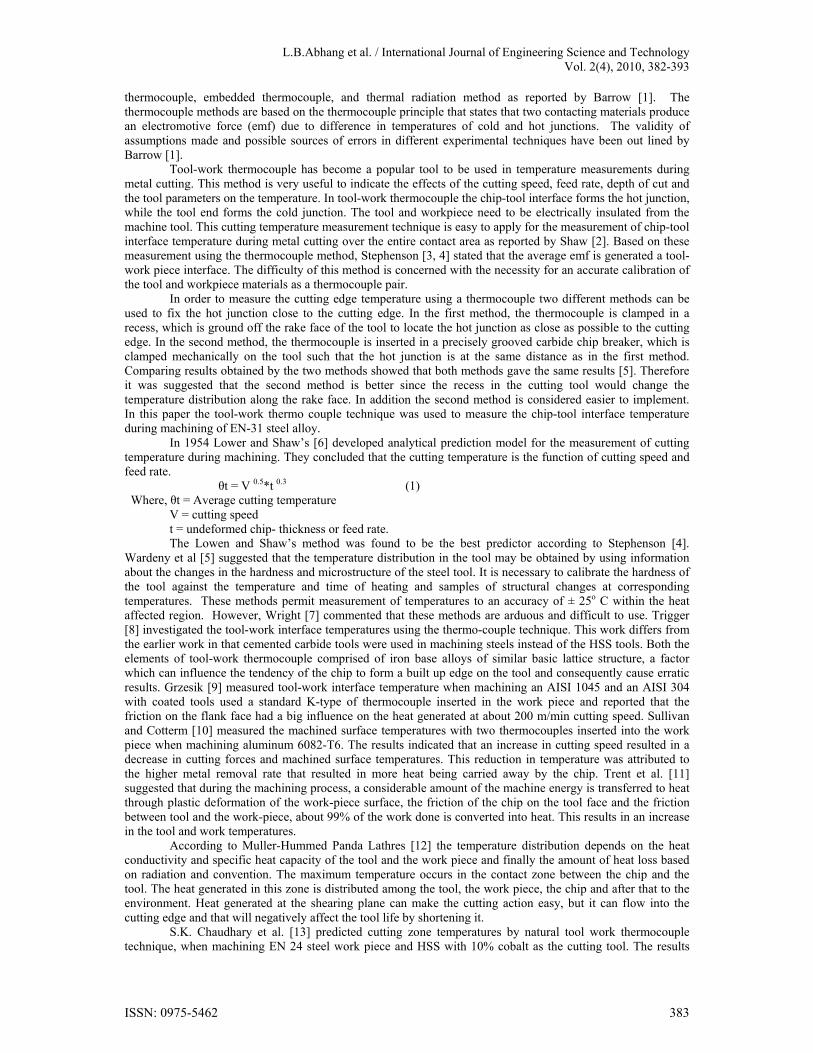
EN-31 steel is widely used in automotive industry for producing automotive components such as roller bearing, ball bearing, spline shaft, shearing blades, die parts etc. Therefore this steel is chosen for experimental investigation and tool used is carbide inserts. Experiments were conducted to determine the effects of the tool geometry parameters and the cutting conditions on the chip-tool interface temperature during the turning of EN-31 steel with tungsten carbide cutting tools. In order to ensure the repeatability of the temperature measured using the tool-work thermocouple technique, cutting tests were repeated three times. Fig6 shows the typical temperature readings as a function of cutting time. Three new cutting tools (fresh) were used to eliminate the effect of tool wear. The cutting conditions in this case were as follows: v= 112 m/min, f = 0.06 mm/rev and d= 0.2mm.The results revealed that the values of cutting temperatures are comparable in the three cases. The cutting conditions used in this experiment were the cutting speed, feed rate, depth of cut and tool nose radius. Factorial design with eight added centre points (24) used in this work is a composite design. So, 24 experiments repeated thrice were conducted and the chip-tool interface temperature of all the components was measured.
ISSN: 0975-5462 389
L.B.Abhang et al. / International Journal of Engineering Science and Technology Vol. 2(4), 2010, 382-393
Fig.6.Repeatability of the chip-tool interface temperatures (v=112m/min,f= 0.06mm/rev,d= 0.2mm)
ANOVA was performed to find the statistical significance of the process parameters and their interactions. The results of ANOVA for cutting temperature are shown in table 4. This table also shows the percentage contribution of each factor and interaction in addition to the sum of squares, mean squares, degree of freedom and F value. Examination of F-values in this table indicate that the variables, cutting speed, feed rate, depth of cut and tool nose radius are significant at 95% confidence level. It is also clear from the results of ANOVA that the cutting speed & feed rate the dominant factors determining the chip-tool interface temperature followed by depth of cut and tool nose radius. However, the effect of interaction of cutting speed and depth of cut and second order term effect of cutting speed (V2) are significant at the 95% confidence level. In order to understand the machining process, the experimental results were used to develop the mathematical models using response surface methodology (RSM). In this work a commercially available statistical software package (Minitab) was used for the computation of the regression constants and exponents. The proposed first order model developed from the above functional relationship using response surface method is as follows: Tc = 32.7 + 2.16 v + 764 f + 206 d – 40.9 r (8) The transformed equation of chip tool interface prediction is as follows: LnTc = 4.92 + 0.441 lnv + 0.329 lnf + 0.316 lnd – 0.132lnr (9) Tc = 137.00 (v0.441 f0.329 d0.316 r – 0.132) (10) Equation (9) is derived from the eqn (8) by substituting the coded values of X1, X2, X3 and X4 in terms of lnv, lnf, lnd, and lnr. The analysis of variance and F- ratio test have been performed to justify fitness of the mathematical model. Since the calculated value of the F-ratio is more than the standard (table value) of the F ratio for the chip-tool interface temperature as shown in table5, the model is adequate at 95% confidence level to represent the relationship between the machining response (cutting temperature) and the considered machining parameters (cutting speed, feed, rate, depth of cut and tool nose radius) of the steel turning process. The multiple regression coefficient of first order model was found to be 0.9760. This shows that the first order model can explain the variation to the extent of 97.60%. In order to see whether a second order model can represent better than the first order or not a second-order model was developed. The second order cutting temperature model thus developed is given as below: Tc = -31.8 + 4.25 v + 680 v + 298 d – 63.5 r + 1.17 vf -396 fd + 0.148 vr + 247 fr -0.838vd -22.7dr – 0.0132v2 (10) Where Tc is the estimated response of cutting temperature on a logarithmic scale and X1, X2, X3 and X4 are logarithmic transformation of cutting speed, feed rate, depth of cut and tool nose radius. The analysis of variance for the second-order model is shown in the table 6. Since F calculated is greater than F table value, there is a definite relationship between the response variable and the independent variables at 95% confidence level. The multiple regression coefficient of the second order was found to be 0.9890. This means that the second order can explain the variation to the extent of 98.97%. Since the difference of the multiple regression coefficients between the first order and the second order is only 0.013, so it can concluded that the first order is adequate to represent the EN-31 steel turning process. The first- order model was used to study the effect of different process parameters on the cutting temperature values. Each temperature value represents the average of chip-tool interface temperature during steel turning operation. Effect of cutting conditions on chip-tool interface temperature: a) Effect of cutting speed
Chip-tool interface temperature is closely connected to cutting speed. Figure7shows the effect of cutting speed on the cutting temperatures (chip-tool interface temperature). With increase of cutting speed, friction increases, this induces an increase in temperature in the cutting zone. The significance of cutting speed for the cutting temperature agrees with the results of Muller et al [12]. In this respect, the temperature
420
440
460
480
10 20 30 40 50 60 70 80 90Chip‐tool interface
temp.0c
Cutting time (sec)
Test No.1
Test No.2
Test No.3
ISSN: 0975-5462 390
L.B.Abhang et al. / International Journal of Engineering Science and Technology Vol. 2(4), 2010, 382-393
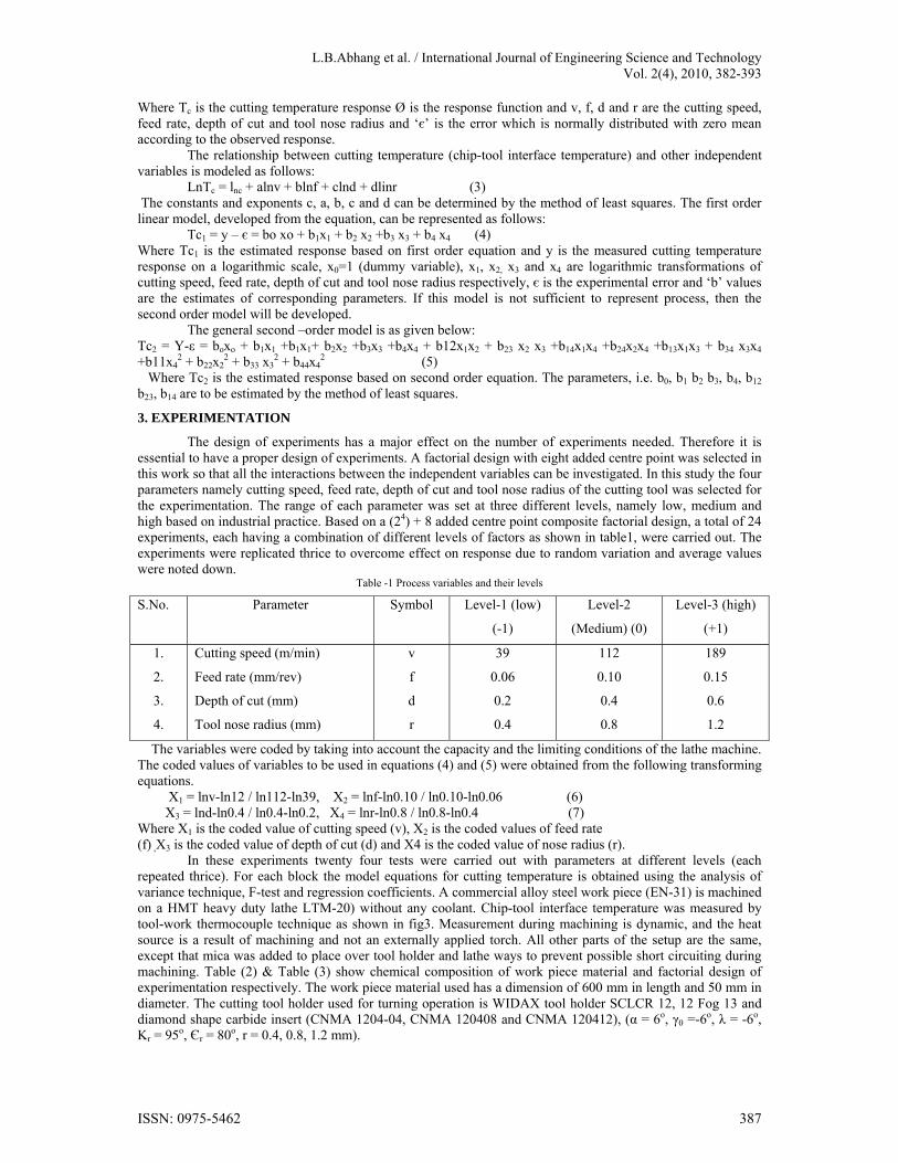
measurement by tool-work thermocouple indicates that for a speed of 39m/min, the maximum temperature is 187.62oc. When cutting speed increases from39m/min to 189m/min the increase in temperature in cutting zone of 174%. The same trend was obtained for different feed rate values of 0.06mm/rev. and 0.15mm/rev. as shown in fig7. This result agrees with Muller et al [12] and Fnides [18].
Fig.7. Effect of cutting speed and feed rate on cutting temperature (d=0.2mm,r=0.4mm)
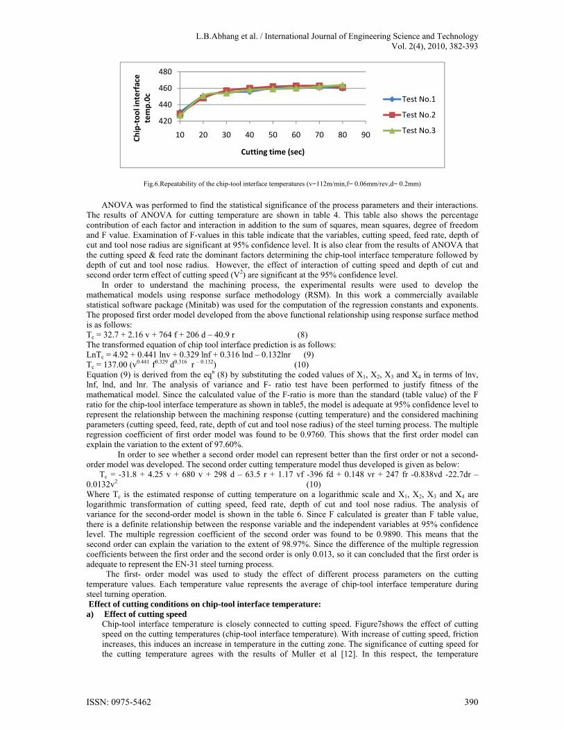
b) Effect of feed rate Figure8 shows the change of temperatures in cutting zone according to the feed rate for the machining of different cutting speed. With the increase in feed rate, section of chip increases and consequently friction increases as reported by Shaw [2], this involves the increase in temperatures, it agrees with Shaw [2], Stephenson [4] and Fnides [18]. As the feed rate increases from 0.06mm/rev to 0.15mm/rev, the temperature increases in 38.57%. This result agrees with Fnides [18]. However, the cutting speed appeared to have more pronounced effect on the cutting temperatures than the feed rate as shown in fig8.
Fig.8.Effect of feed rate on cutting temperature (d=0.2mm, r=0.4mm)
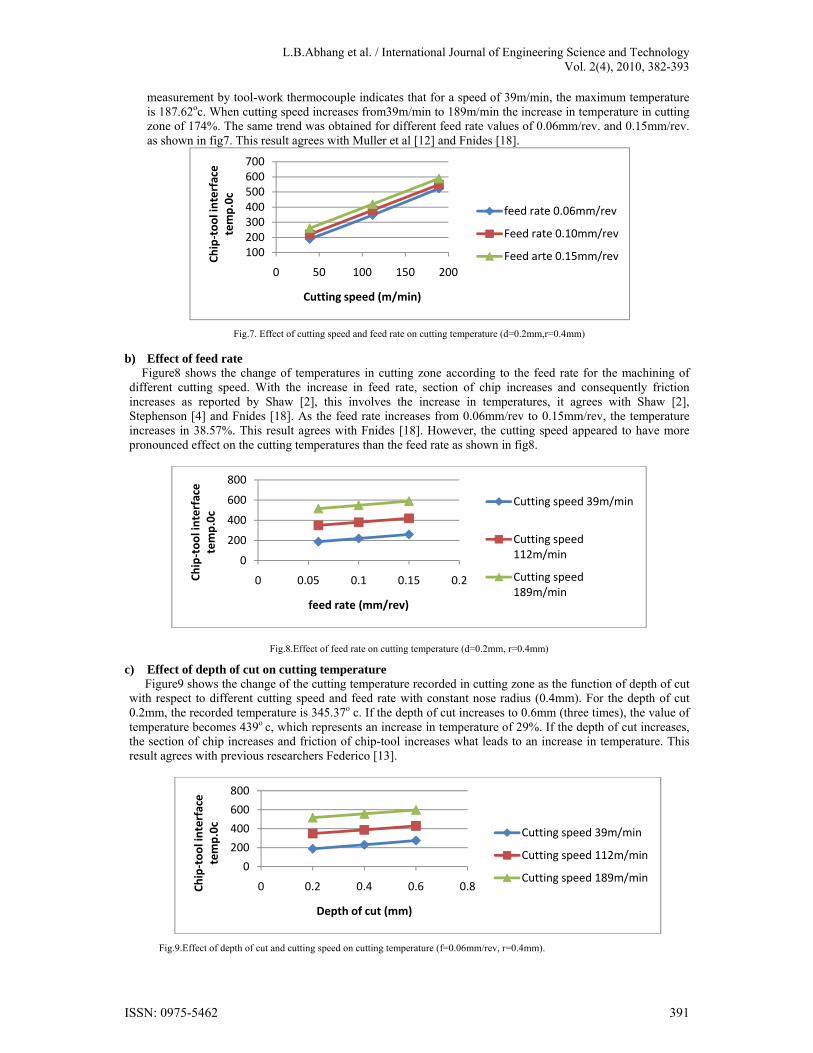
c) Effect of depth of cut on cutting temperature Figure9 shows the change of the cutting temperature recorded in cutting zone as the function of depth of cut with respect to different cutting speed and feed rate with constant nose radius (0.4mm). For the depth of cut 0.2mm, the recorded temperature is 345.37o c. If the depth of cut increases to 0.6mm (three times), the value of temperature becomes 439o c, which represents an increase in temperature of 29%. If the depth of cut increases, the section of chip increases and friction of chip-tool increases what leads to an increase in temperature. This result agrees with previous researchers Federico [13].
Fig.9.Effect of depth of cut and cutting speed on cutting temperature (f=0.06mm/rev, r=0.4mm).
100200300400500600700
0 50 100 150 200
Chip‐tool interface
temp.0c
Cutting speed (m/min)
feed rate 0.06mm/rev
Feed rate 0.10mm/rev
Feed arte 0.15mm/rev
0
200
400
600
800
0 0.05 0.1 0.15 0.2Chip‐tool interface
temp.0c
feed rate (mm/rev)
Cutting speed 39m/min
Cutting speed 112m/min
Cutting speed 189m/min
0
200
400
600
800
0 0.2 0.4 0.6 0.8Chip‐tool interface
temp.0c
Depth of cut (mm)
Cutting speed 39m/min
Cutting speed 112m/min
Cutting speed 189m/min
ISSN: 0975-5462 391

L.B.Abhang et al. / International Journal of Engineering Science and Technology Vol. 2(4), 2010, 382-393
d) Effect of tool nose radius Figure10 shows the effect of tool nose radius on the cutting temperature with different cutting speed, for the nose radius of 0.4mm, the recorded temperature is 348.54o c, if the tool nose radius increases to 1.2mm (either three times), the values of cutting temperature becomes 297.88oc, which represents a decrease in temperatures of approximately 21% while machining with higher tool nose radius. From fig10 clearly shows that cutting temperature reduces at higher values of nose radius. During machining, using a tool with small tool nose radius, the area of contact available for conduction between the tool and work piece is small compared with that with a higher tool nose radius. Hence, the reduction of the heat conduction area promotes local temperature rise along the cutting edge. Earlier investigation of the effect of tool nose radius on the surface residual stresses induced during hard machining showed that increasing the tool nose radius results in lower values of tensile residual stresses when using sharp tool [Kishawy, 16]. These results agree with the current findings since tensile residual stresses induced during machining are temperature related.
Fig.10.Effect of Tool nose radus on cutting temperature (d=0.2mm,f=0.06mm/rev)
CONCLUSIONS
1) In this study average chip-tool interface temperatures have been experimentally studied using the tool-work thermocouple technique. Based on the parametric study, a first-order and second -order empirical models of the chip-tool interface temperatures has been developed for turning of EN-31 steel alloy with tungsten carbide tools by response surface methodology coupled with factorial design.
2) The developed empirical relation agrees well in velocity with the Shaw’s nondimensional model. The first-order and second- order mathematical models are found to be adequately represent the cutting temperatures. The model developed in the research produces smaller errors and has satisfactory results, since multiple regression coefficient of the first order and second order temperature prediction model is approximately 0.99 (R2 = 99%).Therefore the proposed model can be utilized to predict the corresponding cutting temperatures of EN-31 steel at different parameters in turning. This can also be used for metal cutting process optimization, increasing productivity and reducing manufacturing costs.
3) The established equation clearly revealed that the cutting speed is main influencing factor on chip-tool interface temperature as compared to others. It has been shown that increasing cutting speed, feed rate and depth of cut lead to an increase in cutting temperature. However, increasing the tool nose radius decreases the cutting temperature. A good combination among the cutting speed, feed rate, depth of cut and tool nose radius can generate minimum cutting temperature during steel turning. Response surface methodology coupled with factorial design of experiments actually save a lot of time and cost of experiments.
4) The tool-work thermocouple technique is the best method for measuring the average chip-tool interface temperature during metal cutting. The benefits of using the tool-work thermocouple are its ease of implementation and its low cost as compared to other thermocouples.
ACKNOWLEDGEMENT
The authors would like to express their deep gratitude to the Department of mechanical engineering of Aligarh Muslim University (AMU), for providing the laboratory facilities and financial support.
REFERENCES
[1] G. Barrow, ANN, CIRP 22,203-211.1973 [2] Shaw, M.C, Metal cutting principles, Oxford University, press, Londan, 1984 [3] D A Stephenson, Metal cutting theory and practice, chapter-7 cutting temperatures, (www.google.co.in)pp-415-419. [4] D.A. Stephenson, Tool –work thermocouple temperature measurements: theory and implementation issues, Proceedings of
winter Annual meeting of ASME, Anaheim CA.November (1992), pp-18-95. [5] EI Wardany, T.I Mohammed, E, Elbestawi, M.A., Cutting temperature of ceramic tools in high speed machining of difficult to
cut materials. Int.J.Mech Tools,Manuf. (1996), 36(5), 611-634.
0100200300400500600
0 0.5 1 1.5
Chip‐tool interface
temp.0c
Tool nose radius (mm)
Cutting speed 39m/min
Cutting speed 112m/min
Cutting speed 189m/min
ISSN: 0975-5462 392

L.B.Abhang et al. / International Journal of Engineering Science and Technology Vol. 2(4), 2010, 382-393
[6] Lowen E.G. and Shaw M.C, on the analysis of cutting tool temperatures, Transactions of the ASME, 001.76 pp-217-231, (1954).
[7] P.K Wright, Correlation of tempering effects with temperature distribution in steel cutting tools, J.Eng.Ind.100, 1978.131-136. [8] Trigger, K.J. Progress report No.1, on chip-tool interface temperature Trans.ASME, 70, pp-91-98, (1948). [9] Grzesik, W, Experimental investigation of the cutting temperature when turning with coated Index able inserts .Int.J, of
Machine tools and manufacture, 39 pp 355-369,(1999). [10] O,Sullivan and Cotterm, Temperature measurement in single point turning , Journal of material processing technology
vol.118pp.301-308,(2001) [11] Tent,E M . and Wright,P.K. Metal cutting theory ,forth edition, Butterworth- Heinwmann, Boston, MA,2000. [12] Mullar-Hummed,p and Lahr’s,M, A new instrument to optimize cutting process, In situ temperature measurement on diamond
coated tools, Innovations in material research vol.no.pp.01-9,(1996). [13] S.K Choudhary, G.Bartarya, Role of temperature and surface finish in predicting tool wear using neural network and design of
experiments.Int. J.of machine tools and manufacture,43, (2003), 747-753. [14] Federico M. Aheiro Reginalot, Coelho, Lincdnc, Brandao, Turning hardened steel using coated carbide at high cutting speeds.
J.of the Braz.soc.of Mech.sci.and Engg.(2008), vol.xxx.no.2 1109 [15] H.Ay, W.J Yang, Heat transfer and life of metal cutting tools in turning, Int,J. Heat and mass transfer,41,(1998),613-623, [16] Kishawy,H.A. Elbestawi, M.A, Effect of edge preparation and cutting speed on surface integrity of die materials in hard
machining, ASME Int.Eng. Congr, Exp. Manf.sci, Techno, (1998), 269-276. [17] B.Fnides, M.A. Yallese, H, Aouici, Hard turning of hot work steel AISI H11: Evaluation of cutting pressure, resulting force and
temperature, ISSN1392-1207, Mecanika, 2008.Nr.4 (72). [18] Bus,C. Touwen, A.L. Veenstra, P.C. and Van Der Wolf A.C.H, Thermoelectric characteristics of carbides, proceedings of the
12th Int, Machine tool Design and Research, 1971,pp.397-400. [19] Bryne, Gerry, Thermoelectric signal characteristics and average interfacial temperatures in the machining of metals under
Geometrically, Defined conditions, Int,J. machine tools for manufacturing. Vol.27, No.2, pp, 1987, 215-224.
ISSN: 0975-5462 393


![High-temperature production logging tool - Cardinal · PDF fileMadden High-Temperature PIT High-temperature production logging tool Flask OD: 1.6875 in [4.29 cm] Sensor package OD:](https://img.pdfslide.us/doc/110x75/5a99805b7f8b9a18628d9e8d/high-temperature-production-logging-tool-cardinal-high-temperature-pit-high-temperature.jpg)