Embed Size (px)
Citation preview

WiFi-NC : WiFi Over Narrow Channels
Krishna Chintalapudi⋆, Bozidar Radunovic†, Vlad Balan‡, Michael Buettener§,Srinivas Yerramalli‡, Vishnu Navda⋆, and Ramachandran Ramjee⋆
⋆ Microsoft Research India; † Microsoft Research UK; ‡ USC; §University of Washington
ABSTRACTThe quest for higher data rates in WiFi is leading to the de-velopment of standards that make use of wide channels (e.g.,40MHz in 802.11n and 80MHz in 802.11ac). In this paper,we argue against this trend of using wider channels, and in-stead advocate that radios should communicate over multi-ple narrow channels for efficient and fair spectrum utiliza-tion. We propose WiFi-NC, a novel PHY-MAC design thatallows radios to use WiFi over multiple narrow channels si-multaneously. To enable WiFi-NC, we have developed thecompound radio, a single wideband radio that exposes theabstraction of multiple narrow channel radios, each with in-dependent transmission, reception and carrier sensing capa-bilities. The architecture of WiFi-NC makes it especiallysuitable for use in white spaces where free spectrum maybe fragmented. Thus, we also develop a frequency band se-lection algorithm for WiFi-NC making it suitable for use inwhite spaces. WiFi-NC has been implemented on an FPGA-based software defined radio platform. Through real exper-iments and simulations, we demonstrate that WiFi-NC pro-vides better efficiency and fairness in both common WiFi aswell as future white space scenarios.
1. INTRODUCTIONOver the past decade, WiFi data rates have seen over a
100x increase. This was achieved through advances in phys-ical layer wireless communication techniques (e.g.,OFDM,64 QAM and MIMO) that provided increased spectral effi-ciency (bits/s/Hz). As further improvements in spectral ef-ficiency become harder to achieve, using wider channels isbeing viewed as a solution to attain higher data rates. To-day, 802.11n already allows for 40 MHz channels while theupcoming 802.11ac proposes 80 and 160 MHz channels.
In this paper we argue against this obvious approach ofmerely increasing the channel width to increase wireless datarates. Instead, we espouse the opposite – that the channelsbe no wider than existing 20 MHz WiFi channels and ideallybe narrower, say 5 MHz or even 2 MHz. In order to achievehigher data rates then, unlike current day devices that operateover only one channel at a time,we propose WiFi-NC a novelphysical and MAC design that allows devices to run WiFi onseveral narrow channels, simultaneously and independently.
For example, a device must be able to use (transmit/receiveon) eight 5 MHz channels instead of one 40 MHz channel.This diametrically opposite view is designed to address thefollowing three key inefficiencies of current single (wide)channel systems (Section 3).
First, inefficiencies arise when heterogeneous radios co-exist. While WiFi is designed to be fair to devices oper-ating in the same channel, operation of 40 MHz devicesnear 20 MHz devices leads to starvation [1]. Consequently,802.11n standard mandates devices to reduce their channelwidth to 20 MHz immediately upon detecting any coexist-ing 20 MHz device. As a result, in practical 802.11b/g/ndeployments, 802.11n devices are often relegated to usingonly 20 MHz channels. To the best of our knowledge, nowork has addressed this practical and common inefficiencyin WiFi, which is bound to only get worse as 802.11ac de-vices with 80 MHz radios become available. In contrast, a40/80 MHz WiFi-NC radio configured with two/four 20 MHzchannels can make full use of its 40/80 MHz radio while stillcoexisting fairly with other 20/40 MHz networks.
Second, it is well-known that, due to MAC overheads suchas backoffs, the increase in PHY data rates does not trans-late to commensurate gains in TCP/UDP throughput [22,17]. To address this inefficiency, 802.11n standards supportMAC-layer frame aggregation that allow frame sizes of upto 64KB, thereby reducing the relative impact of the MACoverhead. While frame aggregation works well for bulk dataflows, other traffic such as TCP acks, VoIP packets and shortHTTP flows are not amenable to such aggregation. The useof narrow channels in WiFi effectively also elongates packettransmission times relative to MAC overhead (for a givenframe size, transmission time doubles when channel widthis halved), thereby achieving higher throughput.
Third, fragmented spectrum can result in inefficient usage.For example, WhiteFi [4] uses variable width channels foroperation in fragmented white spaces. However, the restric-tion of being able to use a single channel (wide or narrow) ata time, limits WhiteFi’s ability to efficiently use free parts ofthe spectrum. For example, two 6 MHz narrow channels of aWiFi-NC radio can operate simultaneously on either side ofa 6 MHz operating TV channel, while a single-channel sys-tem like WhiteFi will be restricted to choosing only one of
1

the two bands. The ability to use multiple narrow channelssimultaneously, allows us to devise an optimal throughputmaximizing spectrum selection scheme,TMax, that is notpossible in single channel systems.
Related work that comes closest to WiFi-NC is FICA [22].FICA splits a single OFDM physical channel into narrowersub-channelsand allows different devices to access them.However, sub-channels differ from narrow channels in a veryfundamental way – in FICA, a new transmission opportunityarises only when the entire wide channel is idle; then, trans-missions by devices over different sub-channels are tightlytime synchronized (≈ 10µs) Thus, FICA is essentially awide single-channel system with sub-channels that are inter-dependent. While FICA addresses the MAC inefficiency is-sue, the lack of independence among sub-channels precludesFICA from solving the inefficiencies due to heterogeneousradio co-existence or fragmented spectrum.
The centerpiece of WiFi-NC is thecompound radio, anovel design, that uses asingle physical wideband radio butprovides the abstraction of several independent narrow bandradios – radiolets, to the MAC layer. Each radiolet allowsfor independent carrier sensing, transmission and receptionof packets in its own narrow channel. Radiolets are entirelyimplemented as digital circuits and provide the low cost andform factor benefits of digital processing.
The fundamental challenge in designing a compound ra-dio is enabling efficientinterference isolationamong the ra-diolets – a compound radio must be able to simultaneouslycarrier sense, receive, and transmit over different radio-letswithout any inter-dependence. Note that, even if conven-tional radios supported full duplex communication [7, 12,19] over wide bands, we cannot simply divide the full du-plex wide channel into multiple full duplex narrow chan-nels and independently transmit/receive over these narrowchannels. This is because while a full duplex radio will can-cel out the spectral leakage of the narrow channel OFDMtransmission at thetransmitter, the spectral leakage can stillcause severe degradation in adjacent narrow channels at thereceiver(since the narrow channels are not synchronized).Thus, in order to achieve channel isolation, the compoundradio usessharp elliptic filtersat both the transmitter and re-ceiver (Section 5). These filters allows us to use very narrowguard bands between the radiolets (100KHz in our imple-mentation), thereby paying an overhead of only 5% or 2%for a 2 MHz or 5 MHz narrow channel, respectively.
Another fundamental effect of using narrow channels isthe need forpreamble dilation. Since narrow channels trans-mit information at a slower rate, PHY layer preambles takelonger to transmit. While the longer preamble results in onlya small overhead for WiFi-NC (because data transmissiontimes also dilate), a bigger issue is if this dilation results inincreased carrier sensing time – in this case, WiFi-NC wouldneed larger slots, which will severely affect channel utiliza-tion [17]. In order to avoid this problem, the compound ra-dio uses energy detection to ensure carrier sensing time in
WiFi-NC stays the same as in WiFi while employing cross-correlation over the dilated preamble in parallel for OFDMframe synchronization and frequency offset estimation.
We have prototyped the compound radio and WiFi-NCon a FPGA-based software defined radio platform. Throughboth real experiments on our testbed (Section 8) as well asextensive simulations (Section 9), we show that WiFi-NC isboth more efficient and fair than WiFi. Further, while op-erating in white spaces, we show that WiFi-NC is able toachieve up to 121% higher throughput than WhiteFi [4] inthe presence of background transmitters.
While the use of narrow channels has significant efficiencybenefits, the primary cost is increased logic/memory require-ments both at the transmitter/receiver (e.g., transmit andre-ceiver filters, decoding logic per narrow channel, etc.). How-ever, as the FPGA/ASIC sizes grow benefiting from Moore’slaw, we believe that the additional logic/memory require-ments will not pose a significant constraint.
In summary, our paper makes three key contributions:
• The simple insight that radios with multiple independentnarrow channels instead of a single wide channel can im-prove the efficiency of WiFi in many practical settingssuch as heterogenous radio co-existence, at high PHYspeeds and operation in fragmented white spaces.
• WiFi-NC, a novel PHY-MAC design that operates WiFiindependently over multiple narrow channels, and its im-plementation in the form of a compound radio on a FPGA-based software defined radio platform.
• TMax algorithm for maximizing throughput by opti-mal frequency selection for WiFi-NC radios operatingin white spaces.
2. RELATED WORKThere has been tremendous amount of work targeted to-
wards improving WiFi and wireless communication. We dis-cuss a few papers that are most relevant to WiFi-NC here.
Performance. A number of papers [13, 15, 20, 22] haveproposed novel techniques to improve WiFi performance.
FICA [22] is closest to WiFi-NC in terms of advocatingfor fine-grain access. However, FICA proposes the use ofsubchannelsfor fine-grain access which is fundamentallydifferent from the narrow channels of WiFi-NC. Subchan-nels in FICA require asynchronoussystem, where all nodesin carrier sense range must transmit within a few microsec-onds of each other. While it may be possible to time/frequencysynchronize all APs under one management, FICA will notperform well in practical settings where WiFi APs from sev-eral autonomous systems (businesses/homes) co-exist andare not time/frequency synchronized. Furthermore, even withtime/frequency sychronization, FICA does not tackle the in-efficiencies that arise due to radios with different channelwidths or operation in fragmented spectrum.
Coexistence.SWIFT [21] tackles the problem of coexis-tence of wide band radios in the presence of narrow band de-
2

vices. The SWIFT radio detects narrow band transmissionsand then weaves together the unused (non-contiguous)bandsinto one wireless link by transmitting only on the unoccu-pied frequencies. While both WiFi-NC and SWIFT supportnon-contiguous operation, SWIFT still uses the entire avail-able, and potentially wide, band as a single channel, thus,suffering the same inefficiencies as WiFi.
Variable Channel Width. The use of 5 or 10 MHz chan-nels can increase range and reduce power consumption [5].However, the channel width adaptation in previous work [5]only configures the radio toone of 5, 10, 20 or 40MHzchannel for asinglecommunicating pair of radios. Coexis-tence/fairness will be an issue if multiple networks are con-figured with different channel widths. In WiFi-NC, each ra-dio can choose to use one or more independent narrow chan-nels, thus, gaining the benefits of narrow channels withoutsacrificing coexistence.
Guard bands. A number of techniques to mitigate theproblem of adjacent channel interference was studied in [11].The authors found that the use of guard bands was the mostefficient solution to the problem. The issue of appropriatesize for the design of guard bands was considered in [25].The authors show that the size of guard band needs to beadapted based on the location of the wireless nodes. How-ever, the software digital filters used in [24, 25] were Ham-ming window filters that do not have the sharp cutoff proper-ties of the elliptic filters used in WiFi-NC (Section 5). Thus,we are able to show that even a small fixed guard band isconservative enough for our needs. Moreover, a system likeGanache [25] can also help adapt the guard band size inWiFi-NC dynamically.
Full-duplex. Recently, full-duplex single channel wire-less communication systems have been proposed [7, 12, 19].The key challenge in these systems is eliminating the self-interference of the local transmitter. Note that, if these sys-tems operate over the standard 20MHz WiFi channel, theywould also suffer the same MAC overhead inefficiencies asWiFi. Full-duplex communication is an orthogonal featureto WiFi-NC and can be added to the narrow channels ofWiFi-NC.
Fairness.802.11-based wireless networks exhibit unfair-ness due to a number of reasons including hidden termi-nals [8], capture effect [16], exponential backoffs (shorttermunfairness) [9], etc. WiFi-NC is focused on the problem ofunfairness that arises when two or more networks operateover frequency bands that overlap (Section 3).
Overlapping Channels. Authors in [3] show significantunfairness in chaotic WiFi deployments where WiFi chan-nels of adjacent access points can overlap and argue that bet-ter channel allocation and power control can help improveefficiency and fairness. Similarly, authors in [18] proposea frequency hopping algorithm called MAXchop for avoid-ing unfairness in uncoordinated deployments. Compared tothese approaches, the narrow channel model of WiFi-NC re-duces the possibility of partial overlap in channels.
White spaces.Closest to WiFi-NC is WhiteFi [4], a WiFi-like system for TV white spaces. WhiteFi includes a spec-trum assignment algorithm that maximizes a multichannelairtime metric called MCham and an algorithm called SIFTfor detecting APs of varying channel widths. While WhiteFisupports variable channel width access, WhiteFi only sup-ports contiguous operation over the channel. As we shallsee in Section 7, the contiguous access restriction resultsin efficiency loss due to coexistence as well as due to theconservative behavior of the MCham metric. Since WiFi-NC supports independent narrow channels, non-contiguousoperation through suppression of one or more narrow chan-nels provides significant efficiency benefits when operatingin fragmented white space spectrum. Authors in [24] pro-pose Jello, a per-session FDMA system for latency sensitiveapplications such as streaming media. The focus is on uti-lizing (non-contiguous) white space spectrum over sessiondurations rather than on a per-packet basis as in WiFi-NC. Inaddition, Jello does not consider fairness among distributednodes, a key feature of WiFi-NC.
3. MOTIVATION FOR WIFI-NCExisting wideband radios are monolithic, and access the
channel in an "all-or-none" fashion. This design is ineffi-cient in multiple settings and also leads to unfair channel ac-cess. We highlight these inefficiency and unfairness issuesby using three examples.Example 1 - Heterogeneous Radios: Inefficiency in Fre-quency. Consider the concurrent operation of two WLANs(Figure 1a) – an 802.11g WLAN1 (transmitter T1, receiverR1) operating on 20 MHz channel 3 and an 802.11n WLAN2(T2, R2) operating on 40 MHz channel 3. As dictated bythe 802.11n standard, the 802.11n radio detects the 20MHztransmitter and reconfigures itself to only operate on the 20MHzchannel 3 (In fact, we were unable to get our 802.11n radioto operate in 40MHz mode in any of 2.4GHz channels inour lab due to this reason). Thus, transmitters T1 and T2 al-ternatively use the 20MHz band while 20MHz of frequencyremains completely unused.
The above 802.11n mandate was a result of the obser-vation that operation of 40 MHz 802.11n pre-standard de-vices (not subject to the above mandate) alongside 20 MHz802.11g devices led to extreme unfairness and even star-vation. To understand the reason for this unfairness con-sider the concurrent operation of three WLANs (Figure 1b) -WLAN1 (transmitter T1, receiver R1 ), operating on 20MHzChannel 6; WLAN2 (T2, R2) operating on 20 MHz channel11; and WLAN3 (T3, R3) operating on 20 MHz channel 9.Since T3 is able to carrier sense both T1 and T2, 802.11based CSMA dictates that it must wait untilboth T1 andT2 are not transmitting. However, T1 and T2 do not inter-fere with each other and may transmit whenever T3 is nottransmitting. As depicted in Figure 1b, whenever T1 finishestransmitting a packet, T2 is still transmitting and vice-versa.Thus, T3 never finds its channel free for transmission result-
3

(a) Example I (b) Example I (partial overlapping) (c) Example II
1: Examples
0
5
10
15
20
25
30
35
40
1 Active Link 2 Active Links 3 Active Links
TC
P T
hro
ug
hp
ut
(Mb
ps)
Channel-6
Channel-9
Channel 11
Aggregate
2: Unfairness due to partial channel overlap
ing in its starvation.The above starvation effect also manifests itself when WiFi
devices operate over overlapping 20MHz channels.To demon-strate this effect in a practical setting, we setup three iden-tical 802.11b/g Netgear APs inside a lab area, and we hadone client associated with each AP. The APs are configuredto operate in channels 6, 9 and 11. The Figure 2 shows av-erage TCP throughput at the clients for three different set-tings: (1) only one client is downloading at any time, (2)two clients R1 and R2 on non-overlapping channels, 6 and11, downloading, and (3) all three clients are simultaneouslydownloading. From (1) and (2), it is clear that TCP flows onchannel 6 and 11 are independent and do not interfere witheach other when operating simultaneously. However, whenall three flows are active, the client on channel 9 receives al-most negligible throughput (570Kbps) compared to the othertwo clients (20 Mbps each) as depicted in case (3).Example 2 - MAC Overhead: Inefficiency in Time. An-other source of well-known inefficiency [22], illustrated inFigure 1c, arises from the fact that as the device bandwidthincreases, while the time to transmit packets becomes smaller,the MAC overheads such as carrier sense and backoffs re-main constant. 802.11n attempts to combat this unfairnessby allowing for aggregated frames up to 64KB in size butthis requires delaying frames at the interface in order to ag-gregate a large number of smaller packets and is not suitablefor applications such as VOIP or short HTTP transactions.
An alternate approach that increases efficiency but does notrequire larger frame sizes is simply the use of narrow chan-nels. As seen in the Figure, reducing channel width from20MHz to 5MHz simply results in quadrupling of the packettransmission time (the MAC overheads don’t change). Thus,by elongating packet transmission time, narrow channels areable to better amortize the MAC time overheads.
Note that there is a new inefficiency introduced due to nar-row channels, namely, the guard band or the gap betweentwo 5MHz channels. We show how this overhead can bekept very small (2% for 5MHz channels) in Section 5.Example 3 - Fragmented Spectrum: The recent FCC rul-ing of T.V white spaces allows secondary devices to trans-mit in parts of the spectrum unoccupied by primary trans-mitters such as T.V broadcasts operating over 6 MHz chan-nels. Such an opportunistic scenario often requires devicesto operate in a fragmented spectrum. Consequently, a whitespace device with 40 MHz radio bandwidth may not findeven a single continuous span of 40 MHz. A device that al-lows independent channel access and communication overseveral narrow channels (say, eight 5 MHz channels) will al-low the use of fragmented spectrum more efficiently sincethe white space device can simply transmit around any oc-cupied T.V. Channels.This example shows that the futurewhite space devices need to support non-contiguous oper-ation which comes naturally to a device that has multipleindependent narrow channels.
4. WIFI-NCIn section 3 we saw that devices can achieve fairness, in-
creased efficiency and can potentially better use fragmentedspectrum if they used multiple independent narrow channelsinstead of a single wide channel. Given that WiFi alreadyprovides fair access to devices operating in the same chan-nel (narrow or wide) through CSMA and backoff, WiFi-NCsimply allows devices to operate WiFi independently overmultiple narrow channels.
Figure 3 shows an illustration of WiFi-NC node config-ured with four 5MHz narrow channels using a 20MHz radio.The WiFi-NC MAC maintains independent random backoff
4

3: WiFi NC implements WiFi over several narrow channels
counters and performs carrier sensing on each narrow chan-nel. Whenever the backoff counter expires for a given nar-row channel, a packet from the transmit queue is transmit-ted over the corresponding narrow channel. Similarly, pack-ets can be received independently over narrow channels andplaced in the receive queue. As can be seen from the Figure,the narrow channels are completely independent from eachother. Thus, transmissions can be on-going simultaneouslyto different receivers (e.g., transmission to device 1 and 2),while other narrow channels can be in reception or carriersensing mode. As we show in our evaluations (Section 9),this key property of independent narrow channels help WiFi-NC significantly outperform WiFi in terms of both efficiencyand fairness in many common scenarios.
4.1 Exploring Design ChoicesOff-the shelf radios allow operation on only one channel
at time. In order to implement WiFi-NC there are severaldifferent alternatives. In this section, we consider theseal-ternatives.Use multiple narrowband radios on the same device.Sev-eral papers have advocated the use of multiple radios ona single node for better performance [2, 14]. Thus, onecould consider implementing WiFi-NC using multiple nar-row band radios. However, apart from several practical short-comings such as cost, form factor, etc., there is also a funda-mental drawback with such an approach – isolation require-ment in the form of large guard bands between radios. Forexample, WiFi radios use a guardband of 3 MHz betweentwo adjacent channels for interference free operation. Thismeans that in order to create a compound radio of 80MHzwith four 20 MHz radios, one would require guardbandsworth 15 MHz (three 3 MHz in between the four radios andtwo on either side) - reducing spectral efficiency to 80%.This loss of spectral efficiency is further exacerbated as oneuses narrower channels, say, 5MHz wide.Use the sub-carrier structure of OFDM itself to enablefine-grain access.Prior work such as FICA [22] suggeststhat different nodes may use different sub-carriers withinthesame underlying physical channel to create sub-channels.However, in this approach actions such as Clear ChannelAssessment (CCA), transmission and reception performedby different devices across all sub-channels must be tightly
time synchronized. This is because in OFDM, sub-carriersoverlap with each other and their accurate spacing and timesynchronization is key to enable decoding at the receiver.Consequently, independent CCA, transmission and recep-tion over sub-channels is not possible and leads to the sameinefficiencies in co-existence between narrow and widebanddevices described in Section 3.Our Approach - Compound Radio. In order to enable mul-tiple narrow channels, we propose a novel PHY-MAC design– the compound radio. The compound radio,while usinga single wideband physical radio device, performs digitalprocessing to provide the abstraction of multiple indepen-dent radios to the MAC layer.This is achieved by perform-ing channelization digitally through digital filters and digitalmixers as described in Section 5. Since digital filters allowfor extremely cheap and high performance filters in com-parison to analogue filters, digitally implemented adjacentchannels require “very thin” guard bands (100 KHz in ourimplementation). Further, unlike overlapping sub-carriers inOFDM, these channels are completely separate from eachother and have absolutely no cross-talk among them, allow-ing complete independent operation.
5. COMPOUND RADIO ARCHITECTUREAs discussed in Section 4, the compound radio provides
an abstraction of multiple narrow-band radios while usingonly a single physical wideband radio. In this section, westart by describing the functioning of a conventional OFDMradio focusing only on the components that are necessary forproviding the required background and then follow with ourproposed architecture for the compound radio.
5.1 A Conventional RadioAs depicted in Figure 4 a typical radio transmitter or re-
ceiver consists of two key parts - an analogue front end andthe digital baseband. Almost all the complex physical layerpacket processing such as MIMO, OFDM, encoding and de-coding etc. are implemented in the digital baseband sincedigital circuits provide the benefits of low cost, form factorand ease of implementation. However, as it is hard to designcheap digital circuits at clock rates of several GHz, the sig-nal must first be down-converted from the carrier frequency(2.4/5 GHz) to the baseband frequency (20 MHz in case of20 MHz channels) using the analogue frontend.Analogue Transmit and Receive Filters.In order to avoidinterference from/to devices operating over adjacent chan-nels, radios use transmit and receive filters in the analoguefront end (Figure 4). These filters, only let frequencies withinthe bandwidth of the channel to pass through (say 2.4-2.42GHz for 20 MHz channel 1).Mixer. The mixer, at the receiver, is responsible for down-converting the received signal at carrier frequency (2.4 GHz)to baseband frequencies (0-20 MHz) to be presented to thedigital baseband. At the transmitter, it up-converts the base-band signal to carrier frequency making it suitable for trans-
5

4: Conventional Radio and Compound Radio
mission.ADC and DAC. These are used to convert between the ana-logue signal at baseband frequencies to digital signal at thereceiver and vice-versa at the transmitter.AGC. Typical DAC circuits are designed to operate correctlyfor a specific input voltage range (say 0.5V to -0.5V). Thus,Automatic Gain Control (AGC) appropriately scales the ana-logue signal from the antenna to ensure that the signal fromthe antenna is within the desired voltage range.Baseband transmitter/recevier. Generation and receptionof packet including MIMO, OFDM, encoding, decoding, mod-ulation and demodulation are handled by the baseband trans-mitter and receiver using digital circuits.
5.2 A Compound RadioThe key idea behind the compound radio architecture is
to use digital mixers and transmit/receive filters in the base-band to create narrow channels digitally.Figure 4 depictsthis idea for a compound radio that implements four 5 MHznarrow channels.
5.2.1 Compound Transmitter
The compound transmitter comprisesN transmitterlets,each responsible for transmitting data over one narrow chan-nel of width B
N, whereB is the bandwidth of the analogue
front end. Each transmitterlet consists of a baseband trans-mitter, an upsampler, a digital low pass filter and a digitalmixer. The outputs of each of the transmitterlets are thenadded digitally and passed on to the analogue frontend whichis identical to the analogue frontend of a conventional radio.Baseband Transmitter. The baseband transmitter is iden-tical to the baseband transmitter used in any conventionalradio, except for two differences. First, since it operatesover a channel that is1
Nthe bandwidth, it uses1
Nnumber
of subcarriers intended for the wide band channel. Second,it operates at1
Nthe sampling frequency of that used for the
wideband radio, since the required Nyquist sampling rate forthe narrow channel is1
Nof that for the wide channel with
bandwidthB. As discussed later in this section, this allowsindividual transmitterlets to operate at1
Nthe clock rate and
hence keep the total number of operations required per sec-ond across theN transmitterlets the same as the wide bandradio.Upsampler. In order to match the sampling rate of the wideband radio, the digital samples from the baseband transmit-ter are upsampled by a factor ofN . During upsampling,N − 1 additional digital samples are inserted between twoconsecutive samples through interpolation. There are sev-eral ways to interpolate – in our implementation, we use aDFT based upsampler.Low Pass Filter. A sharp low pass filter (described in detaillater in the section), ensures that the signal is indeed limitedto within 0 to B
NMHz.
Mixer. Prior to the mixer, the digital signals in all trans-mitterlets have frequencies between 0 -B
NMHz. The dig-
ital mixer for thekth transmitterlet shifts these frequenciesby (k−1)B
NMHz to ensure that the digital signal emanating
from it has frequencies in the range( (k−1)BN
, kBN
) MHz. Themixer essentially multiplies each digital sample by a com-plex sinusoid of frequency(k−1)B
NMHz and can be cheaply
implemented using a ROM and two digital multipliers.
5.2.2 Compound Receiver
The compound receiver architecture is symmetric to thatof a compound transmitter and consists of multiplereceiver-lets- each to receive packets over one narrow channel. Eachreceiverlet comprises, a mixer, a low pass filter, a down sam-
6

pler and finally the baseband receiver. The mixer of thekth
receiverlet downs shifts the frequency of the received signalby (k−1)B
NMHz. This frequency downshifting ensures that
frequencies corresponding to thekth receiverleti.e., in therange( (k−1)B
N, kB
N) MHz are mapped to the range(0, B
N)
MHz. A low pass filter between(0, B) MHz then extractson the band corresponding to the receiverlet. A1
Ndown-
sampler then reduces the sampling rate by a factor of1N
bysimply droppingN − 1 consecutive samples after pickingeach sample. The baseband receiver is identical to the base-band receiver of a conventional radio except that it operatesat 1
Nthe sampling rate and uses1
Nsub-carriers of that used
for the wideband channel.
6. DESIGN CHALLENGESWe faced two fundamental challenges in the design of the
compound radio.Interference Isolation. In WiFi-NC, nodes must be able
to carrier sense, receive and transmit simultaneously on adja-cent narrow channels. Since we use OFDM in each narrowchannel for efficiency, the leakage from OFDM transmis-sions into the adjacent narrow channels can be significant(Section 6.1). We need to be able to isolate this interferencewithin each narrow channel.
Preamble Dilation. While the use of narrower channelsincreases efficiency in WiFi-NC, channel widths below 20 MHzcan lead to inefficiencies from increase in physical layer pream-ble lengths since narrow channels inherently transmit infor-mation at a lower rate.
In the rest of this section, we describe in detail each ofthese challenges and the approach we use to address them.
6.1 Interference IsolationFigure 5 depicts a possible scenario with three WiFi-NC
nodes. Node A simultaneously transmits to nodes B and Cover narrow channels 1 and 3. At the same time nodes B andC transmit to node A over narrow channels 2 and 4 respec-tively. The spectrum of each of these transmissions as seenat Node A is also depicted in Figure 5 – node A’s receiver ex-periences very high interference from its own transmissionsin narrow channels 1 and 3 (about -20 dBm at the receiveantenna, assuming a transmit power of 20 dBm [12]). NodeB and C are located far away and their signals at A are ex-tremely weak, about -85 dBm and -80 dBm, respectively.
Let as assume that we limit guard bands between nar-row channels to 100 KHz so that even for a 2 MHz narrowchannel, spectral wastage is only 5%. Figure 5 also depictsthe typical OFDM spectral leakage in the absence of filters.The power in the adjacent channels decays to approximatelyabout -40 dBm in the adjacent channels. In order to pro-vide perfect interference isolation, the transmit and receivefilters must attenuate the OFDM spectral leakage to belownoise levels (-90 dBm or lower). Thus, we require an attenu-ation of the transmit signal by least 50dB to provide interfer-ence isolation. Thus, in our implementation, we usetransmit
Filter Type Bandwidth 5 MHz Bandwidth 2 MHz# Adds # Mults # Adds # Mults
Chebyshev 76 76 48 48Butterworth 492 492 208 208
Elliptic 26 20 22 17
1: Filter Comparison - 60dB attenuation, 100KHz guard-band
and receive filters that provide an attenuation of about 60 dBwithin 100kHz.Note that this represents an extreme scenariofor WiFi-NC where the self-interference is maximum com-pared to the received signal.
Table 1 shows the number of adders and multipliers re-quired to achieve our design (100 KHz guardband, 60 dBattenuation) by different choices of filters. As indicated inTable 1, Elliptic Filters [10] satisfy our requirements withthe least number of elements. Consequently, we use Ellipticfilters in our implementation.
We have implemented the compound radio on an FPGAbased software defined radio platform (Section 8). Figure 6depicts the transmitted spectrum measured at a distance of1cm from the transmit antenna for a 16QAM, 3/4 coding (36Mbps) OFDM transmission over a 5 MHz narrow channel.As seen from Figure 6, the spectral leakage due to OFDM issignificantly high and decays to only about -60dBm even ata distance of 2MHz from the transmitted band. The figurealso shows the spectrum when using our transmit filter. Wecan see that the spectrum decays to about -90dBm beyondthe 100 KHz guard band.
6.1.1 Effect of Carrier Frequency Offsets
Due to manufacturing variations, two different radios in-variably have acarrier frequency offset(CFO) - small dif-ference in their carrier frequencies. These differences im-ply that the channel boundaries of two communicating ra-dios will not be exactly aligned. This misalignment placesa practical lower limit on how narrow guardbands can be inWiFi-NC since using guardbands smaller than the CFO willlead to interference leakage into adjacent narrow channels.The 802.11 standard requires CFO for any two pair of radiosto be under 25ppm (60 KHz) in the 2.4 GHz band and un-der 20ppm (116 KHz) in the 5.8 GHz band. CFO for whitespace devices operating in the 200-800 MHz will be under20 KHz (assuming 25ppm). Our choice of 100KHz guard-band, thus, accommodates CFO in both white spaces as wellas at 2.4 GHz in 802.11. In the 5.8 GHz band, however,a slightly larger guardband, perhaps 150 KHz wide, mayberequired. In practice, since manufacturers typically ensurethat the CFO is safely below the maximum allowed limit,we believe that CFO will not be an issue for WiFi-NC.
6.1.2 Effect of limited bits in ADC
While one can achieve self-interference isolation only byusing sharp filters, this is possible only if the ADC of the
7

5: A possible scenario in WiFi-NC 6: Spectrum of transmission with and without filters
radio is able to support a wide range of power levels. AnADC typically accepts as input an analogue signal that iswithin ±0.5 V (or a similar range). Consequently, receivedsignal is typically scaled (by a gain controller) down (or up)to lie within this range. The range of an ADC is specified inbits. Each extra bit of the ADC allows for discerning signalswith half the amplitude and hence one fourth the power – inother words, each bit provides 6 dB resolution.
Since our testbed platform uses 14 bit ADCs, it has arange of 84 dB which means the radio is sensitive to sig-nals that are 84 dB below the strongest received signal. Inthe face of -20dBm self interference then, a weak signal thatis -85dBm effects only the last three to four bits of the ADCbut is still discernible. However, many commercial systemsuse ADCs with 9 to 12 bits. Thus, for an ADC with 10 bits(60 dB range), this signal cannot be discerned at all since thelast bit corresponds to -80dBm.
In devices with fewer ADC bits, analogue self-interferencecancelation [19] or signal-inversion using Balun transformer [12]can be used to reduce the strength of self-interference so thatpower levels are in the range of the ADC. For example evena reduction of self-interference power by 25dB provided byQuellan QHx220 noise cancelers used in [19] or the 45dBover 40 MHz provided by Balun transformers [12] will per-mit devices with 9 bit ADCs to receive weak signals at -85dBm while transmitting on adjacent channels.
Note that this cancelation is distinct from cancelation neededin full duplex systems [7, 19] – the cancelation here merelyhelps bring the power levels within the range of ADC so thattransmit and receive can operate onseparatechannels whilefull duplex systems require cancelation of the full transmitsignal so that one can receive on thesamechannel.
6.1.3 Filter Induced Interference
A filter restricts the spectrum of the signal by spreading(smoothing) it in time. The sharper the filter, the more thespreading. Figure 7 depicts the impulse response of our filteri.e., the transmitted signal resulting from passing a single
7: Filter induced multipath
digital sample through the filter. As seen from the figure, thefilter spreads the sample for several microseconds in time.This spreading in fact is the same effect as spreading dueto indoor multipath environments. Such spreading resultsin self-interference between symbols termed Inter SymbolInterference (ISI).Need for longer Cyclic prefix (CP).In order to combat ISI,OFDM uses the cyclic prefix, which pre-appends 25% of theOFDM symbol and extends the symbol. The spread versionof the previous symbol, thus interferes with the cyclic pre-fix and does not adversely effect the original symbol. Typ-ical spreading due to multipath in indoor environments isless than 800 ns, consequently, WiFi uses 800 ns cyclic pre-fix. However, use of sharp filters in the compound radio in-creases this spreading. As seen in Figure 7, the spreading de-cays by about 10dB within 800 ns and to about 15 dB within1.6µs. While low data rate modulations such as BPSK re-quire about 6 dB SNR, higher data rate modulations such as16 QAM may require up to 14 dB SNR. In our implementa-tion we found that a cyclic prefix about 1.6µs long allowedfor successful reception even at higher data rate modulationsuch as 16 QAM.Increasing Number of Subcarriers.Cyclic prefix is a waste-
8

ful part of the transmission and results in a decrease in spec-tral efficiency. In order to keep efficiency the same after ex-tending the CP by a factorη, the symbol duration must alsobe stretched by the same factorη. In OFDM this is typicallyachieved by increasing the number of subcarriers by a fac-tor of η. In our implementation we found thatη = 2 wassufficient to combat the impulse response of the sharp 60 dBfilters. Consequently, while WiFi uses 64 subcarriers in a 20MHz band, WiFi-NC must use 128 subcarriers.
6.2 PHY Preamble Dilation for channel widthsbelow 20 MHz
Physical layer preambles are crucial for packet receptionand perform several key functions.Since channels narrowerthan 20 MHz result in slower transmission of informationcompared to WiFi, it would take longer to transmit WiFi’sphysical layer preambles in each narrow channel of WiFi-NC. In this section we describe the effects of thispreambledilation and describe techniques to address them.
6.2.1 Preamble Dilation in WiFi-NC
The WiFi preamble can be divided into two logical parts- thepre-synchronizationand thepost-synchronization. Letus look at the functions of these two parts:Pre-synchronization Preamble.This part of the preambleis primarily responsible for three important functions.ClearChannel Assessment (CCA) to sense if carrier is idle,OFDMframe synchronization to detect OFDM symbol boundaryfor decoding andf requency offset estimation to correct formismatches in carrier frequency between transmitter and re-ceiver. WiFi uses Pseudo-random Noise (PN) sequences toperform these three functions. The performance of a PN se-quence depends on the length (number of PN samples) of thesequence. A narrow channel that has1
Nthe bandwidth will
takeN times longer to transmit the same number of samples.Consequently,this part of the preamble dilates by a factor ofN , whereN is the number of radiolets.Post-synchronization Preamble.After the receiver is syn-chronized to the transmitter, it must estimate and compen-sate for the distortions caused by the wireless medium. Toaid this, the transmitter sends training symbols, one (or more)for each OFDM subcarrier. The receiver then estimates thedifferences between the received and expected symbols andcorrects for them. The key observation here is thatthe num-ber of training symbols is proportional to the number of sub-carriers. Thus, while a narrow channel with1
Nthe band-
width transmitsN times slower, the number of sub-carriersand hence the number of training symbols to be transmittedis also 1
Ntimes lesser. Estimation of MIMO parameters, is
based on a similar approach and is also proportional to thenumber of subcarriers. Consequently, since WiFi-NC uses128 subcarriers instead of 64 used in WiFi (to counter thefilter-induced interference),this part of the preamble dou-bles in duration but is independent of channel width.
How much does the preamble dilate for WiFi-NC?The pre-synchronization preamble in WiFi is 4µs while thepost synchronization preamble varies between 4 OFDM sym-bols (16µs in 802.11g) to 9 OFDM symbols (16µs in 802.11n).Thus, for a WiFi-NC transmitter withN radiolets, the du-ration of the preamble transmission will be4N + 32 µs(802.11g) to4N + 72 µs (802.11n).
Preamble dilation can potentially affect the performanceof WiFi-NC in two ways. First, it can reduce the efficiencysince dilated preambles take longer to transmit and second,it can mean requiring larger slot durations than 9µs. Weexamine each of these next.
6.2.2 Effect of preamble dilation on efficiency
While the preamble transmission duration increases, sodoes the duration to transmit data. For example, for WiFi-NC with a 2 MHz narrow channel, the 802.11n 300 Mbpspreamble will dilate from40 µs to 112 µs. At the sametime, the time to transmit a 1500-byte packet elongates from40 µs to 400 µs. Thus,the ratio of preamble transmissiontime to packet transmission time still reduces significantlyfrom 100% to 28%, resulting in significant overall gain in ef-ficiency as the 20 MHz WiFi channel is reduced to a 2 MHznarrow channel in WiFi-NC.
6.2.3 Effect of preamble dilation on slot duration
The slot duration of WiFi is fixed to be 9µs, 4µs of whichare allocated to perform CCA, 1µs allows for propagationdelays and 5µs for switching from receive to transmit mode.Since WiFi nodes use the pre-synchronization part of thepreamble to perform CCA, dilation of this part of the pream-ble implies that slots might also need to be dilated since CCAmust be performed within one slot duration.There are twodifferent approaches to tackle this problem.
Decoupling slot width from preamble detection time.As used in WiFi-Nano [17], using interference cancelationand speculative preambles, one can decouple slot width frompreamble detection time. This decoupling allows backoffslots to remain unchanged despite the preamble detectiontimes being longer, thereby, preserving the backoff efficiencyof WiFi.
Energy-based CCA.An alternative is to perform energy-based detection on the first 4µs of the dilated preamble forCCA rather than using preamble detection on the entire pre-synchronization preamble. This again decouples slot widthfrom the other functions of the preamble such as frame syn-chronization and frequency offset estimation (which are per-formed in parallel), thereby, preserving the backoff efficiencyof WiFi.
In this paper, we focus on the energy-basedCCA approach.Fundamentally any CCA scheme must distinguish betweenreceiver noise and harmful external interference, so as toavoid wasteful transmissions in the face of interference fromother RF sources. In our implementation, in order to deemthe channel as busy, the receiver collects samples over a 4ts
9

sliding window (160 samples) and compares whether thesum of their squares (the energy) is larger than a threshold.To calibrate the threshold for each device, we first collectseveral tens of thousands of receiver noise samples in theabsence of external transmissions. The threshold is then cho-sen to be the maximum collected energy over any 4µs win-dow. While one could choose higher values of threshold (e.g.10 dB higher), our choice of threshold is the most conserva-tive – it ensures detection ofanyexternal interference. Be-ing more conservative than WiFi can result in more backoffsthan WiFi in a practical setting (e.g., due to microwaves).Since our experiments were conducted in the 580 MHz band(Section 8), we were not affected by the choice of this thresh-old.
7. WIFI-NC IN WHITE SPACESIn this section we consider the operation of WiFi-NC in
white spaces.The key difference between operation in whitespaces from that in the ISM band (2.4GHz) is that whitespace devices must avoid parts of spectrum occupied by pri-mary users such as TV transmissions that use 6MHz widechannels. This leads to two key requirements for white spacedevices. First, they must be able to operate on fragmentedspectrumi.e.,no single continuous span of spectrum as wideas 40 MHz or even 20 MHz may be available. Second, de-vices need to judiciously pick which parts of the spectrumto transmit on, given that several other white space devicesmay be operating – thespectrum selection problem.
The use of narrow channels allows WiFi-NC to efficientlyuse even narrow intermittent spaces between spectrum sec-tions occupied by primary transmitters. Further, as we shalldescribe in this section, the ability to use multiple indepen-dent channels allows for a greedy distributed algorithm –TMax that maximizes the total expected network through-put across all operating devices.Prior Approach - WhiteFi. The problem of spectrum selec-tion has been examined in WhiteFi [4]. WhiteFi allows theflexibility to select among three possible analogue frontendbandwidths 5 MHz, 10 MHz and 20MHz. While, the abilityto use narrower bandwidths allows WhiteFi to operate over5 MHz or 10 MHz even when there is no span of continuous20 MHz spectrum available, WhiteFi devices may use onlyone channel at time. The authors propose a metric calledMCham that each device maximizes greedily to determinethe center frequency and bandwidth of operation.MCham
metric for a nodek with a certain center frequencyf andfront-end bandwidthB is given by
MChamk(f, B) =B
5
∏
c∈(f,B)
ρk(c) (1)
Here,c corresponds to the 5MHz channels contained inthe frequency span(f − B
2 , f + B2 ), andρk(c) corresponds
to the expected share of nodek in a 5MHz channelc, givenby,
ρk(c) = max
(
Rk(c),1
Lck
)
. (2)
In equation 2,Rk(c) refers to the fraction of residual air-time available in the channelc andLc
k refers to the total num-ber of contenders in the channel.
WhiteFi was faced with a key constraint, i.e., its radioonly supported the notion of asingle channelthat operatedin a contiguous manner over the full bandwidth. This cre-atestwo key disadvantages:1) the need to choose an operat-ing bandwidth (e.g., 5MHz) that may be lower than the fullbandwidth of the radio (e.g., 20MHz); 2) theMCham met-ric has to beconservativesince a wideband radio cannot usethe channel until all overlapping subchannels are free at thesame time leading to theproduct termin Equation 1. Notethat this coupling could also result in starvation, similartothe problem described in Section 3.TMax Algorithm in WiFi-NC. In the case of WiFi-NC,since the radio supportsindependent narrow channels, bothdisadvantages of WhiteFi disappear. The radio can alwaysuse its full available bandwidth since it can operate in a non-contiguous manner around any primary transmitters. Also,since the narrow channels are independent, the available through-put estimate need not be conservative and is simply thesum-mationof throughput in each of its narrow channels. Thus,WiFi-NC uses a new metric called ThroughputMaximal met-ric or TMax for determining its frequency of operation, as
TMaxk(f) =∑
c∈(f)
B
nρk(c) (3)
wheren is number of narrow channels,B is the analoguefrontend’s bandwidth. andf is the set of all narrow channelsin the range(f − B
2 , f + B2 ).
WiFi-NC nodes operating in white spaces, periodicallyscan over the entire available parts of the spectrum comput-ing theTMax metric for part. They then greedily choosef
where the part of spectrum that maximizesTMax. Whentwo or more regions of the spectrum have the same value forTMax, ties are broken by always choosing the lower fre-quency value for operation.Optimality of TMax. It can be shown that, while eachnode greedily uses theTMax algorithm, the scheme iter-atively converges to maximize the expected aggregate net-work throughput across all operating devices and hence theoverall spectrum utilization. In the interest of space, we donot provide the proof in this paper. A detailed proof can befound in [6].
8. RESULTS ON TEST BEDWiFi-NC has been implemented on a DSP/FPGA based
software defined radio platform – the SFF SDR from LyretechInc. SFF SDR uses two Virtex-4 SX35 FPGAs and the DM6446DSP processor from TI. The entire digital baseband of thecompound radio and time-sensitive parts of MAC such asbackoff counters and CSMA have been implemented on theFPGA. We used an off-the-shelf sub-gigahertz analogue ra-dio front end provided by Lyretech that allows transmissionsbetween 360 MHz to 960 MHz. The analogue radio front
10
0 2 4 6 8 10 12 14 16 18 20SNR (dB)
BE
R
6 Mbps (BPSK 1/2) Self Int Off6 Mbps (BPSK 1/2) Self Int On18 Mbps (QPSK 3/4) Self Int Off18 Mbps (QPSK 3/4) Self Int On36 Mbps (16QAM 3/4) Self Int Off36 Mbps (16QAM 3/4) Self Int On
10−6
10−5
10
10
10
10
10−4
0
−1
−2
−3
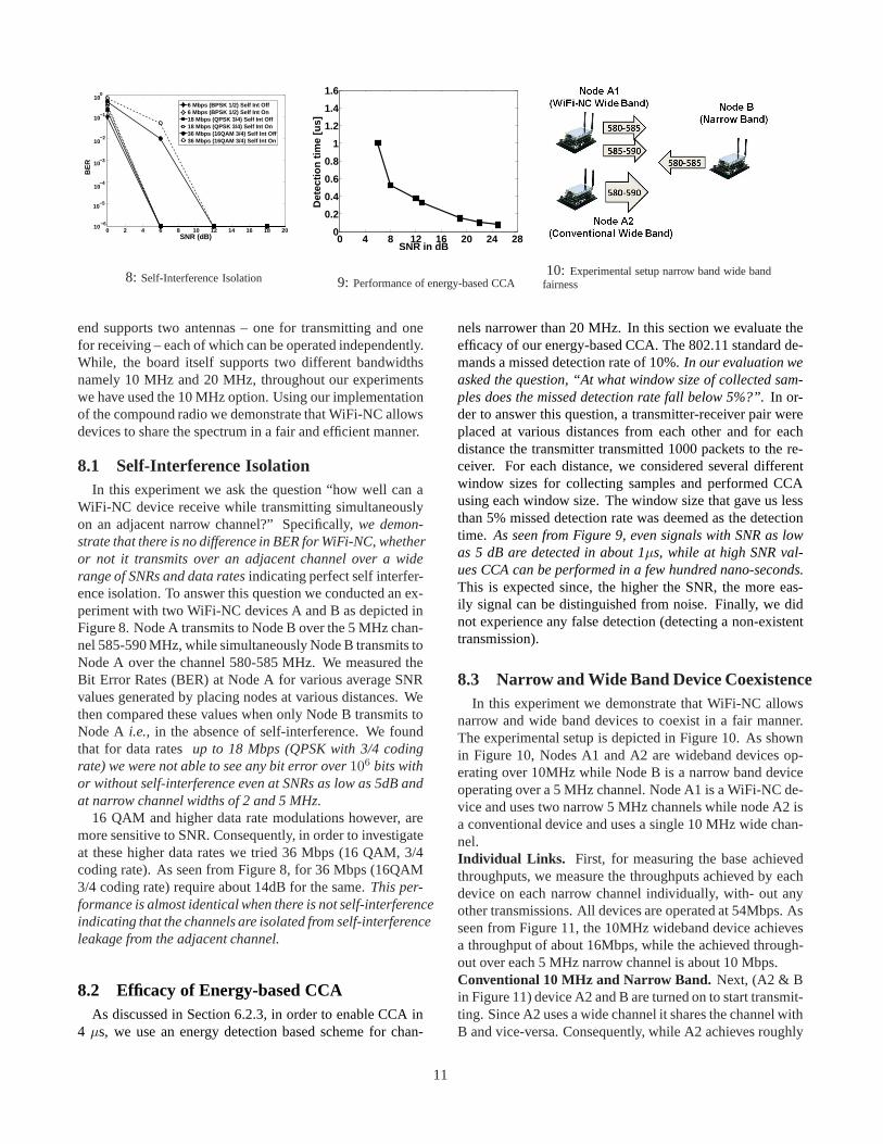
8: Self-Interference Isolation
0 4 8 12 16 20 24 280
0.2
0.4
0.6
0.8
1
1.2
1.4
1.6
SNR in dB
Det
ectio
n tim
e [u
s]
9: Performance of energy-based CCA10: Experimental setup narrow band wide band
fairness
end supports two antennas – one for transmitting and onefor receiving – each of which can be operated independently.While, the board itself supports two different bandwidthsnamely 10 MHz and 20 MHz, throughout our experimentswe have used the 10 MHz option. Using our implementationof the compound radio we demonstrate that WiFi-NC allowsdevices to share the spectrum in a fair and efficient manner.
8.1 Self-Interference IsolationIn this experiment we ask the question “how well can a
WiFi-NC device receive while transmitting simultaneouslyon an adjacent narrow channel?” Specifically,we demon-strate that there is no difference in BER for WiFi-NC, whetheror not it transmits over an adjacent channel over a widerange of SNRs and data ratesindicating perfect self interfer-ence isolation. To answer this question we conducted an ex-periment with two WiFi-NC devices A and B as depicted inFigure 8. Node A transmits to Node B over the 5 MHz chan-nel 585-590 MHz, while simultaneously Node B transmits toNode A over the channel 580-585 MHz. We measured theBit Error Rates (BER) at Node A for various average SNRvalues generated by placing nodes at various distances. Wethen compared these values when only Node B transmits toNode A i.e., in the absence of self-interference. We foundthat for data ratesup to 18 Mbps (QPSK with 3/4 codingrate) we were not able to see any bit error over106 bits withor without self-interference even at SNRs as low as 5dB andat narrow channel widths of 2 and 5 MHz.
16 QAM and higher data rate modulations however, aremore sensitive to SNR. Consequently, in order to investigateat these higher data rates we tried 36 Mbps (16 QAM, 3/4coding rate). As seen from Figure 8, for 36 Mbps (16QAM3/4 coding rate) require about 14dB for the same.This per-formance is almost identical when there is not self-interferenceindicating that the channels are isolated from self-interferenceleakage from the adjacent channel.
8.2 Efficacy of Energy-based CCAAs discussed in Section 6.2.3, in order to enable CCA in
4 µs, we use an energy detection based scheme for chan-
nels narrower than 20 MHz. In this section we evaluate theefficacy of our energy-based CCA. The 802.11 standard de-mands a missed detection rate of 10%.In our evaluation weasked the question, “At what window size of collected sam-ples does the missed detection rate fall below 5%?”.In or-der to answer this question, a transmitter-receiver pair wereplaced at various distances from each other and for eachdistance the transmitter transmitted 1000 packets to the re-ceiver. For each distance, we considered several differentwindow sizes for collecting samples and performed CCAusing each window size. The window size that gave us lessthan 5% missed detection rate was deemed as the detectiontime. As seen from Figure 9, even signals with SNR as lowas 5 dB are detected in about 1µs, while at high SNR val-ues CCA can be performed in a few hundred nano-seconds.This is expected since, the higher the SNR, the more eas-ily signal can be distinguished from noise. Finally, we didnot experience any false detection (detecting a non-existenttransmission).
8.3 Narrow and Wide Band Device CoexistenceIn this experiment we demonstrate that WiFi-NC allows
narrow and wide band devices to coexist in a fair manner.The experimental setup is depicted in Figure 10. As shownin Figure 10, Nodes A1 and A2 are wideband devices op-erating over 10MHz while Node B is a narrow band deviceoperating over a 5 MHz channel. Node A1 is a WiFi-NC de-vice and uses two narrow 5 MHz channels while node A2 isa conventional device and uses a single 10 MHz wide chan-nel.Individual Links. First, for measuring the base achievedthroughputs, we measure the throughputs achieved by eachdevice on each narrow channel individually, with- out anyother transmissions. All devices are operated at 54Mbps. Asseen from Figure 11, the 10MHz wideband device achievesa throughput of about 16Mbps, while the achieved through-out over each 5 MHz narrow channel is about 10 Mbps.Conventional 10 MHz and Narrow Band. Next, (A2 & Bin Figure 11) device A2 and B are turned on to start transmit-ting. Since A2 uses a wide channel it shares the channel withB and vice-versa. Consequently, while A2 achieves roughly
11
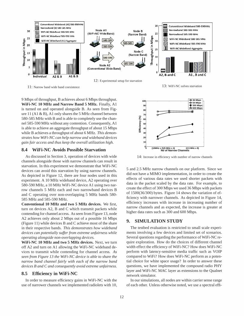
11: Narrow band wide band coexistence
12: Experimental setup for starvation
13: WiFi-NC solves starvation
9 Mbps of throughput, B achieves about 6 Mbps throughput.WiFi-NC 10 MHz and Narrow Band 5 MHz. Finally, A1is turned on and operated alongside B. As seen from Fig-ure 11 (A1 & B), A1 only shares the 5 MHz channel between580-585 MHz with B and is able to completely use the chan-nel 585-590 MHz without any contention. Consequently, A1is able to achieve an aggregate throughput of about 15 Mbpswhile B achieves a throughput of about 6 MHz.This demon-strates how WiFi-NC can help narrow and wideband devicesgain fair access and thus keep the overall utilization high.
8.4 WiFi-NC Avoids Possible StarvationAs discussed in Section 3, operation of devices with wide
channels alongside those with narrow channels can result instarvation. In this experiment we demonstrate that WiFi-NCdevices can avoid this starvation by using narrow channels.As depicted in Figure 12, there are four nodes used in thisexperiment. A 10 MHz wideband device, A2 operating over580-590 MHz, a 10 MHz WiFi-NC device A1 using two nar-row channels 5 MHz each and two narrowband devices Band C operating over non-overlapping 5 MHz bands 580-585 MHz and 585-590 MHz.Conventional 10 MHz and two 5 MHz devices.We first,turn on devices A2, B and C which transmit packets whilecontending for channel access. As seen from Figure 13, nodeA2 achieves only about 2 Mbps out of a possible 16 Mbps(Figure 11) while devices B and C achieve most of the sharein their respective bands.This demonstrates how widebanddevices can potentially suffer from extreme unfairness whileoperating alongside non-overlapping devices.WiFi-NC 10 MHz and two 5 MHz devices. Next, we turnoff A2 and turn on A1 allowing the WiFi-NC wideband de-vices to transmit while contending for channel access.Asseen from Figure 13 the WiFi-NC device is able to share thenarrow band channel fairly with each of the narrow banddevices B and C and consequently avoid extreme unfairness.
8.5 Efficiency in WiFi-NCIn order to measure efficiency gains in WiFi-NC with the
use of narrower channels we implemented radiolets with 10,
0 (10MHz x 2)(5 MHz x 4) (2.5 MHz x 8)0
10
20
30
40
50
60
70
80
90
100
No of Narrow Channels
Effi
cien
cy (
%)
36 Mbps54 Mbps300 Mbps600 Mbps
14: Increase in efficiency with number of narrow channels
5 and 2.5 MHz narrow channels on our platform. Since wedid not have a MIMO implementation, in order to create theeffects of various data rates we used shorter packets withdata in the packet scaled by the data rate. For example, tocreate the effect of 300 Mbps we used 36 Mbps with packetsof 1500(36/300) bytes. Figure 14 shows the variation of ef-ficiency with narrower channels. As depicted in Figure 14,efficiency increases with increase in increasing number ofnarrow channels and as expected, the increase is greater athigher data rates such as 300 and 600 Mbps.
9. SIMULATION STUDYThe testbed evaluation is restricted to small scale experi-
ments involving a few devices and limited set of scenarios.Several questions regarding the performance of WiFi-NC re-quire exploration. How do the choices of different channelwidth effect the efficiency of WiFi-NC? How does WiFi-NCperform with latency-sensitive media traffic such as VOIPcompared to WiFi? How does WiFi-NC perform as a poten-tial choice for white space usage? In order to answer thesequestions, we have implemented the compound radio PHYlayer and WiFi-NC MAC layer as extensions to the Qualnetnetwork simulator.
In our simulations, all nodes are within carrier sense rangeof each other. Unless otherwise noted, we use a spectral effi-
12

0
0.1
0.2
0.3
0.4
0.5
0.6
0.7
0.8
0.9
1 2 4 8 16
Eff
icie
ncy
Spectral Efficiency (bps/Hz)
1 x 20 MHz
2 x 10 MHz
4 x 5 MHz
10 x 2 MHz
20 x 1 MHz
FICA
15: Efficiency for different channelsizes and spectral efficiencies
1 5 10 15 20 25 300
5
10
15
20
25
# of VOIP Transmitters
Ave
rage
Del
ay (
ms)
1 x 20 MHz2 x 10 MHz4 x 5 MHz10 x 2 MHz20 x 1 MHz
16: Average Latency for different chan-nel sizes
0
10
20
30
40
50
0 10 20 30 40
Th
rou
gh
pu
t (M
bp
s)
# Background Transmitters
WhiteFi
WiFi-NC (MCham)
WiFi-NC (Tmax)
17: White space transmitter throughput
ciency value of 2.7 bps/Hz and a radio front-end bandwidthof 20MHz, which is equivalent to the 54 Mbps mode of802.11a/g. Protocol overhead such as header size and ACKlength is modeled on 802.11a. For all WiFi-NC configura-tions, we fixed the guard band size to 100 KHz, same as ourprototype implementation.
9.1 EfficiencyTo understand the trade-off of using smaller narrow chan-
nels, we experimented on a single 20 MHz wide-band linkwith different WiFi-NC configurations (number of channels× channel width). We measure the achieved bit rate whenthe link is saturated with 1500 byte back-to-back packets fordifferent values of spectral efficiency (bps/Hz). Figure 15shows the channel efficiency, which is computed as the ra-tio of the achieved bit-rate to the raw bit-rate, for differentWiFi-NC configurations. For comparison, we also plot thechannel efficiency numbers quoted by FICA [22].
As spectral efficiency increases, the fixed protocol over-heads become increasingly burdensome and consequently,narrower channels provide much better channel efficiencythan using a single wide channel. With a spectral efficiencyof 16 bps/Hz, equivalent to a 320 Mbps bit rate across a 20MHz band (similar to 300Mbps 802.11n), the 20times 1MHz configuration is 60% efficient compared to only 25%when using a single 20 MHz band. In comparison, FICAachieves an efficiency of around 65%. Thus, WiFi-NC isable to match the high efficiency of a synchronous systemlike FICA while still operating in a fully asynchronous man-ner.
9.2 LatencyNarrower channels increase throughput by elongating packet
transmission times; this amortizes the cost of fixed over-heads. However, longer transmission times also increasetransmission latency od each packet which could adverselyaffect latency sensitive traffic such as VOIP. Surprisingly,however, we found that usingnarrower channels actuallyreduces system latencywhen there are multiple clients.
In this experiment, along with a single bulk transmittersaturating the link, we add an increasing number of clients
that each transmit 200B packets every 20 ms representingVOIP payload. Figure 16 shows that, as the number of clientsincreases, narrow channels have lower latency compared toa single 20MHz channel. As the number of clients increaseso does contention and consequently the likelihood of col-lisions. Since latency sensitive clients do not saturate thechannel, using narrower channels reduces the number of con-tenders on any given band and thus reduces latency. In par-ticular, using more channels reduces the incidence of packetcollisions due to choosing the same slot for transmissions byup to 10% (not shown due to lack of space).
9.3 White Space NetworkingWiFi-NC is also well suited for use in white space net-
works where fragmented spectrum is the norm. To demon-strate this, we simulated a white space network based on TVbroadcasters in an urban area according to TV Fool [23].This gave us thirty one 6 MHz TV channels with 12 primarytransmitters. In order to study the impact of backgroundtraffic, among the open channels we randomly distributednarrow-band background transmitters, each of which used aUDP stream to consume 1/3 the capacity of a single 6 MHzband, similar to the evaluation used in WhiteFi [4]. We thenadded a wide-band transmitter that can use up to 4 channels,and we measured its throughput for three different schemes,WhiteFi [4], WiFi-NC with theMCham metric and WiFi-NC with theTMax metric.
Figure 17 shows the throughput as the number of back-ground transmitters increases. With 0 background transmit-ters, WhiteFi can use 4 channels concurrently and achievesa 40 Mbps throughput. However, as more background trans-mitters are added,MCham is forced to select bands thatuse less than four channels to avoid background transmitters.This means that when there are 40 background transmitters,WhiteFi selects only a single channel, and achieves only 12Mbps of throughput. In the case of WiFi-NC withMCham
metric, throughput is higher due to WiFi-NC’s higher effi-ciency and also its ability to contend with each narrow bandtransmitter independently. With 20 background transmitters,this scheme increases throughput by more than 65% com-
13

pared to WhiteFi. However, with 40 transmitters its gainsreduce since theMCham metric selects only one channel.
When WiFi-NC is used with theTMax metric, TMax
always uses four adjacent channels and contends indepen-dently on each one (operating in a non-contiguous manneraround incumbents). Thus, it is able to deliver a throughputgain of up to 121% over WhiteFi.
10. DISCUSSIONThree common concerns with any new wireless design
arebackward compatibility, energy consumption, andimple-mentation complexity.Backward Compatibility. Given that most WiFi devices to-day use 20MHz channels, supporting backward compatibil-ity in WiFi-NC is easy. Upon detecting a 20 MHz transmis-sion in its vicinity, the WiFi-NC radio simply reconfiguresitself to use 20MHz wide channels. For a 80 MHz 802.11nWiFi-NC radio, using four 20 MHz narrow channels canprovide fairness and efficiency gains while being compati-ble to legacy WiFi devices.Energy Consumption. Since the efficiency of WiFi-NCis higher than that of standard WiFi, transmitting the sameamount of information requires radios to be turned on fora lesser amount of time. A large component of the powerconsumed by an RF circuit can be attributed to the analoguecomponents such as amplifiers, analogue filters and the os-cillator. Since WiFi-NC does not require any changes to theanalogue front end, this part of the power consumption issame as that for WiFi. Consequently, we believe that WiFi-NC will also be more power efficient than WiFi.Implementation Complexity. Indeed, the implementationcomplexity of digital logic in WiFi-NC is higher than that ofWiFi. However, digital circuits enjoy the scaling propertiesof Moore’s law. For example, ASICs and FPGAs have seena 300% increase in terms of number of gates in the past fewyears. Given this trend, we believe that accommodating thecomplexity of WiFi-NC on a chip will not be a significantdeterrent in the adoption of WiFi-NC.
11. CONCLUSIONIn order to support gigabit wireless speeds, 802.11 stan-
dards are increasingly being driven towards wide channeldesign. In this paper, we argue for supporting multiple in-dependent narrow channels within a single wideband radioand propose WiFi-NC. To enable WiFi-NC, we propose anovel radio design, the compound radio. Through exper-iments and simulations, we show that WiFi-NC maintainshigh efficiency at high data rates and is able to fairly uti-lize the wideband in the presence of coexisting networks.Further, WiFi-NC is also well suited for future white spacescenarios where spectrum may be fragmented.
12. ACNOWLEDGEMENTSWe thank our shepherd, Brad Karp, and the anonymous
reviewers for their constructive comments.
13. REFERENCES[1] 802.11n Bonding Unfairness.
http://www.zdnet.com/blog/ou/80211n-draft-110-a-kinder-gentler-neighbor/410.
[2] A. Adya, P. Bahl, J. Padhye, A. Wolman, and L. Zhou. A multi-radiounification protocol for IEEE 802.11 wireless networks. InBroadNets, 2003.
[3] A. Akella, G. Judd, S. Seshan, and P. Steenkiste. Self management inchaotic wireless deployments. InACM MobiCom, 2005.
[4] P. Bahl, R. Chandra, T. Moscibroda, R. Murty, and M. Welsh. Whitespace networking with wi-fi like connectivity.ACM SIGCOMM,2009.
[5] R. Chandra, R. Mahajan, T. Moscibroda, R. Raghavendra, andP. Bahl. A case for adapting channel width in wireless networks. InACM SIGCOMM, 2008.
[6] K. Chintalapudi et. al. WiFi-NC: WiFi over Narrow Channels.Technical Report MSR-TR-2012-17, Microsoft Research, 2012.
[7] J. I. Choi, M. Jain, K. Srinivasan, P. Levis, and S. Katti.Achievingsingle channel, full duplex wireless communication. InACMMobiCom, 2010.
[8] S. Gollakota and D. Katabi. Zigzag decoding: Combating hiddenterminals in wireless networks. InACM SIGCOMM, 2008.
[9] M. Heusse, F. Rousseau, R. Guillier, and A. Duda. Idle sense: Anoptimal access method for high throughput and fairness in ratediverse wireless lans. InACM SIGCOMM, 2005.
[10] M. C. Horton and R. J. Wenzel. The Digital Elliptic Filter – ACompact Sharp-Cutoff Design for Wide Bandstop or BandpassRequirements.IEEE transactions on Microwave theory andtechniques, pages 307–314, May 1967.
[11] W. Hou, L. Yang, L. Zhang, X. Shan, and H. Zheng. Understandingcross-band interference in unsynchronized spectrum access. InACMCoRoNet, 2009.
[12] M. Jain et. al. Practical, real-time, full duplex wireless. InACMMobiCom, 2011.
[13] K. Jamieson and H. Balakrishnan. Ppr: Partial packet recovery forwireless networks. InACM SIGCOMM, 2007.
[14] S. Kakumanu and R. Sivakumar. Glia: A practical solution foreffective high datarate wifi-arrays. InACM MobiCom, 2009.
[15] S. Katti, H. Rahul, W. Hu, D. Katabi, M. Medard, and J. Crowcroft.Xors in the air: Practical wireless network coding. InACMSIGCOMM, 2006.
[16] A. Kochut, A. Vasan, A. Shankar, and A. Agrawala. Sniffing out thecorrect physical layer capture model in 802.11b. 2004.
[17] E. Magistretti et. al. WiFi-Nano: Reclaiming WiFi Efficiencythrough 800ns slots. InACM MobiCom, 2011.
[18] A. Mishra, D. Agrawal, V. Shrivastava, S. Banerjee, andS. Ganguly.Distributed channel management in uncoordinated wirelessenvironments. InACM MobiCom, 2006.
[19] B. Radunovic, D. Gunawardena, P. Key, A. Proutiere, N. Singh,V. Balan, and G. Dejean. Rethinking indoor wireless mesh design:Low power, low frequency, full-duplex. InWiMesh, 2010.
[20] H. Rahul, F. Edalat, D. Katabi, and C. Sodini. Frequency-Aware RateAdaptation and MAC Protocols. InACM MobiCom, Beijing, China,September 2009.
[21] H. Rahul, N. Kushman, D. Katabi, C. Sodini, and F. Edalat. Learningto share: Narrowband-friendly wideband wireless networks. In ACMSIGCOMM, 2008.
[22] K. Tan, J. Fang, Y. Zhang, S. Chen, L. Shi, J. Zhang, and Y.Zhang.Fine Grained Channel Access in Wireless LAN. InACM SIGCOMM,August 2010.
[23] TV FOOL. http://www.tvfool.com.[24] L. Yang, W. Hou, L. Cao, B. Y. Zhao, and H. Zheng. Supporting
demanding wireless applications with frequency-agile radios. InUSENIX NSDI, 2010.
[25] L. Yang, B. Y. Zhao, and H. Zheng. The spaces between us: Settingand maintaining boundaries in wireless spectrum access. InACMMobiCom, 2010.
14