Embed Size (px)
Citation preview

Well suited for renovations and retrofit applications.
www.price-hvac.com for additional product information including product videos and brochures.
Price Chilled Sails couple the radiant cooling and heating effects of standard radiant panels with a convective component for increased performance. Their unique shape gives them more surface area than a traditional radiant panel, increasing their radiant capacity and still achieving the high comfort of radiant systems.
Chilled SailsCS Series
Concealed application behind perforated ceiling
Made in North America for shorter lead times and custom capability
Low installation height saves space
Exposed model for architectural appeal
RA
DIA
NT
PR
OD
UC
TS
© Copyright Price Industries Limited 2011. All Metric dimensions ( ) are soft conversion. Imperial dimensions are converted to metric and rounded to the nearest millimetre. H-85
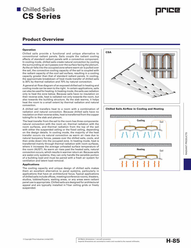
OperationChilled sails provide a functional and unique alternative toconventional radiant panels. Sails couple the radiant coolingeffectsofstandardradiantpanelswithaconvectivecomponent.Incoolingmode,chilledsailscreatenaturalconvectionbycoolingthesurroundingairasitpassesoverthesurfacefacingtheplenum.Astheairfallsintotheoccupiedzonewherewarmairispulledoverthesail,theconvectivecoolingcapacityofthesailiscoupledwiththeradiantcapacityofthecoolsailsurface,resultinginacoolingcapacitygreaterthanthatofstandardradiantpanels.Incooling,theapproximatebreakdownofheatmodetransferofchilledsailsis30%bythermalradiationand70%bynaturalconvection.
Ageneralairflowdiagramofanexposedchilledsailinheatingandcoolingmodecanbeseentotheright. Incertainapplications,sailscanalsobeusedforheating.Inheatingmode,thesailsuseradiationonlytoheatthezonebelow.Becausesailshavenoinsulationontheirreverseside,heatisradiatednotonlytowardstheroom,butalsotowardsthebuildingstructure.Astheslabwarms,ithelpsheattheroomtoasmallextentbythermalradiationandnaturalconvection.
A chilled sail transfers heat to a roomwith a combination ofradiationandnaturalconvection.Becausechilledsailshavenoinsulationontheirreversesides,heatistransferredfromthecoppertubing/fintotheslabandplenum.
Theheattransferfromthesailtotheroomhasthreecomponents:naturalconvectionwiththeroomair,thermalradiationwiththeroomsurfaces, and thermal radiation from the topof the sailwitheitherthesuspendedceilingorthefixedceiling,dependingonthedesigndetails.Incoolingmode,themajorityoftheheattransferoccursvianaturalconvectionaswarmairrisesduetonaturalbuoyancyforces,passesoverthechilledsails,cools,andthensinksdownintotheoccupiedzone.Inheatingmode,heatistransferredmainlythroughthermalradiationwithroomsurfaces,whereitincreasestheaverageunheatedsurfacetemperatureoftheroom(AUST).Aswarmairrisespasttheheatedsails,naturalconvectionoccurs,whichresultsinwarmerreturnair.Becausesailsarewater-onlysystems,theycanonlyhandlethesensibleportionofabuildingloadandmustbepairedwithafreshairsystemforventilationandlatentloadremoval.
ApplicationsThecoolingcapacityanduniquedesignofchilledsailsmakesthemanexcellentalternative topanelsystems,particularly inapplicationsthathaveanarchitecturalfocus.Typicalapplicationsofchilledsailsincludeoffices,meeting/conferencerooms,theaters,studios,lobbies/foyers,waitingareas,oranyareaswereradiantpaneluseisappropriate.ChilledsailsaredesignedforarchitecturalappealandaretypicallyinstalledinT-barceilinggridsorfreelysuspended.
Chilled SailsCS Series
CSA
Chilled Sails Airflow in Cooling and Heating
Cooling
Heating
Sail
Sail
Product Overview
RA
DIA
NT
PR
OD
UC
TS
H-86 All Metric dimensions ( ) are soft conversion. © Copyright Price Industries Limited 2011. Imperial dimensions are converted to metric and rounded to the nearest millimetre.
Chilled SailsCSA
Models
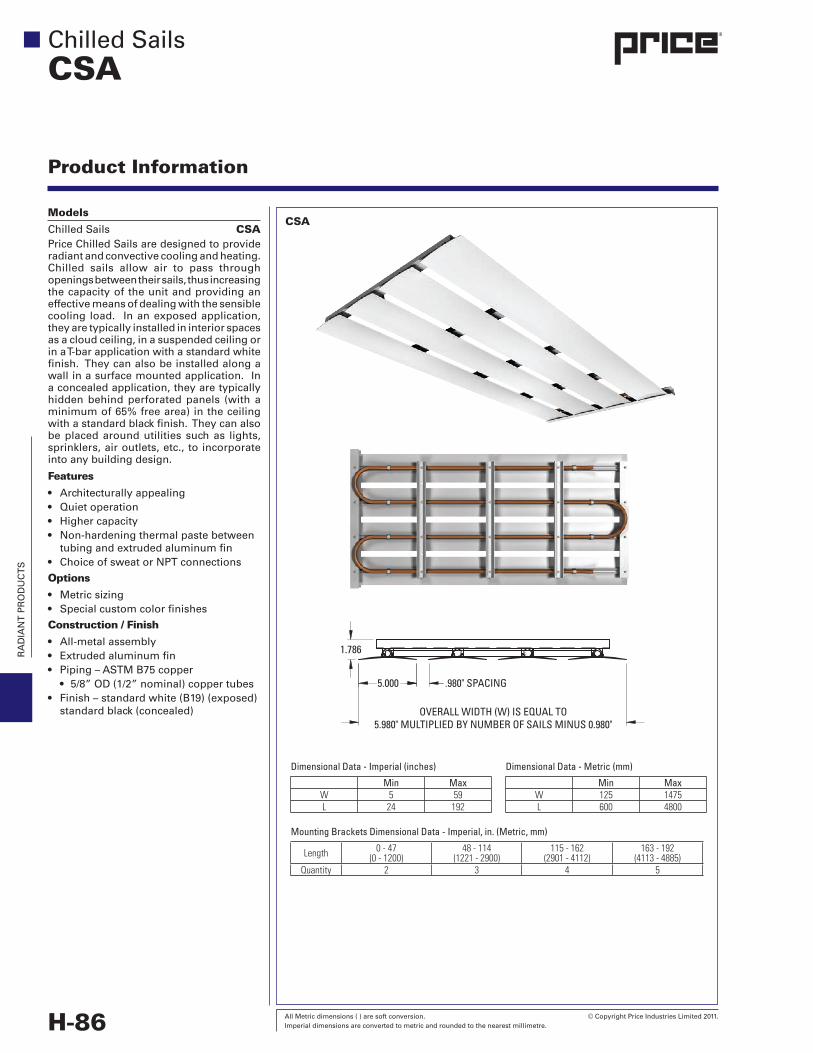
Chilled Sails CSAPriceChilledSailsaredesignedtoprovideradiantandconvectivecoolingandheating.Chilled sails allow air to pass throughopeningsbetweentheirsails,thusincreasingthecapacityoftheunitandprovidinganeffectivemeansofdealingwiththesensiblecooling load. Inanexposedapplication,theyaretypicallyinstalledininteriorspacesasacloudceiling,inasuspendedceilingorinaT-barapplicationwithastandardwhitefinish.Theycanalsobeinstalledalongawallinasurfacemountedapplication.Inaconcealedapplication,theyaretypicallyhiddenbehindperforatedpanels (withaminimumof65%freearea)intheceilingwithastandardblackfinish.Theycanalsobeplacedaroundutilitiessuchas lights,sprinklers,airoutlets,etc.,toincorporateintoanybuildingdesign.
Features
• Architecturallyappealing• Quietoperation• Highercapacity• Non-hardeningthermalpastebetween tubingandextrudedaluminumfin• Choice of sweat or NPT connections
Options
• Metricsizing• Specialcustomcolorfinishes
Construction / Finish
• All-metalassembly• Extrudedaluminumfin• Piping–ASTMB75copper
• 5/8”OD(1/2”nominal)coppertubes• Finish–standardwhite(B19)(exposed) standardblack(concealed)
Product Information
Dimensional Data - Imperial (inches)
Min MaxW 5 59L 24 192
Dimensional Data - Metric (mm)
Min MaxW 125 1475L 600 4800
Mounting Brackets Dimensional Data - Imperial, in. (Metric, mm)
Length 0 - 47 (0 - 1200)
48 - 114 (1221 - 2900)
115 - 162 (2901 - 4112)
163 - 192 (4113 - 4885)
Quantity 2 3 4 5
CSA
5.000 .980" SPACING
1.786
OVERALL WIDTH (W) IS EQUAL TO5.980" MULTIPLIED BY NUMBER OF SAILS MINUS 0.980"
RA
DIA
NT
PR
OD
UC
TS
© Copyright Price Industries Limited 2011. All Metric dimensions ( ) are soft conversion. Imperial dimensions are converted to metric and rounded to the nearest millimetre. H-87
Sail Handing / Coil Connection
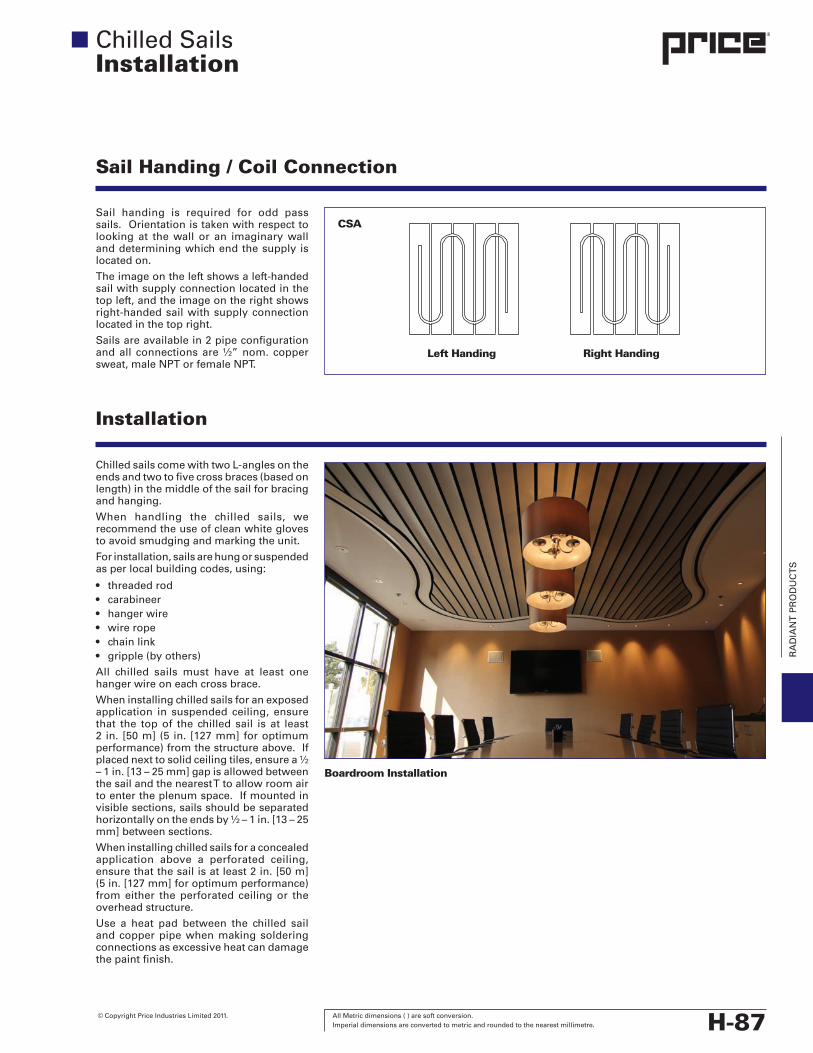
Sail handing is required for odd passsails.Orientationistakenwithrespecttolookingat thewall or an imaginarywallanddeterminingwhichendthesupplyislocated on.
Theimageontheleftshowsaleft-handedsailwithsupplyconnectionlocatedinthetopleft,andtheimageontherightshowsright-handedsailwithsupplyconnectionlocatedinthetopright.
Sailsareavailablein2pipeconfigurationandall connectionsare½”nom.coppersweat, male NPT or female NPT.
ChilledsailscomewithtwoL-anglesontheendsandtwotofivecrossbraces(basedonlength)inthemiddleofthesailforbracingandhanging.
When handling the chilled sails, werecommendtheuseofcleanwhiteglovestoavoidsmudgingandmarkingtheunit.
Forinstallation,sailsarehungorsuspendedasperlocalbuildingcodes,using:
• threaded rod• carabineer• hangerwire• wirerope• chainlink• gripple(byothers)
All chilled sails must have at least onehangerwireoneachcrossbrace.
Wheninstallingchilledsailsforanexposedapplication in suspended ceiling, ensurethat the topof the chilled sail is at least2 in. [50m](5 in. [127mm]foroptimumperformance)fromthestructureabove.Ifplacednexttosolidceilingtiles,ensurea½–1in.[13–25mm]gapisallowedbetweenthe sail and the nearest T to allow room air toentertheplenumspace.Ifmountedinvisiblesections,sailsshouldbeseparatedhorizontallyontheendsby½–1in.[13–25mm]betweensections.
Wheninstallingchilledsailsforaconcealedapplication above a perforated ceiling,ensurethatthesailisatleast2in.[50m](5in.[127mm]foroptimumperformance)fromeither theperforated ceilingor theoverheadstructure.
Use a heat pad between the chilled sailandcopperpipewhenmakingsolderingconnectionsasexcessiveheatcandamagethepaintfinish.
Installation
Chilled SailsInstallation
CSA
Left Handing Right Handing
Boardroom Installation
RA
DIA
NT
PR
OD
UC
TS
H-88 All Metric dimensions ( ) are soft conversion. © Copyright Price Industries Limited 2011. Imperial dimensions are converted to metric and rounded to the nearest millimetre.
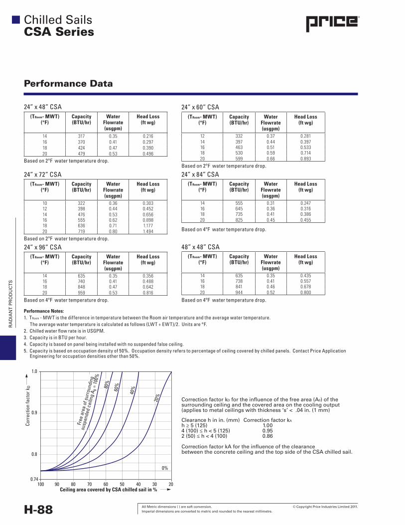
(TRoom- MWT) (°F)
Capacity (BTU/hr)
Water Flowrate (usgpm)
Head Loss(ft wg)
14 317 0.35 0.21616 370 0.41 0.29718 424 0.47 0.39020 479 0.53 0.496
24” x 48” CSA
Performance Data
Performance Notes:1. TRoom - MWT is the difference in temperature between the Room air temperature and the average water temperature. The average water temperature is calculated as follows (LWT + EWT)/2. Units are °F.2. Chilled water flow rate is in USGPM.3. Capacity is in BTU per hour. 4. Capacity is based on panel being installed with no suspended false ceiling.5. Capacity is based on occupation density of 50%. Occupation density refers to percentage of ceiling covered by chilled panels. Contact Price Application Engineering for occupation densities other than 50%.
(TRoom- MWT) (°F)
Capacity (BTU/hr)
Water Flowrate (usgpm)
Head Loss(ft wg)
10 322 0.36 0.30312 398 0.44 0.45214 476 0.53 0.65616 555 0.62 0.89818 636 0.71 1.17720 719 0.80 1.494
24” x 72” CSA
(TRoom- MWT) (°F)
Capacity (BTU/hr)
Water Flowrate (usgpm)
Head Loss(ft wg)
14 635 0.35 0.35616 740 0.41 0.48818 848 0.47 0.64220 959 0.53 0.816
24” x 96” CSA
24” x 60” CSA
(TRoom- MWT) (°F)
Capacity (BTU/hr)
Water Flowrate (usgpm)
Head Loss(ft wg)
14 555 0.31 0.24716 645 0.36 0.31618 735 0.41 0.38620 825 0.45 0.455
24” x 84” CSA
(TRoom- MWT) (°F)
Capacity (BTU/hr)
Water Flowrate (usgpm)
Head Loss(ft wg)
14 635 0.35 0.43516 738 0.41 0.55718 841 0.46 0.67820 944 0.52 0.800
48” x 48” CSA
(TRoom- MWT) (°F)
Capacity (BTU/hr)
Water Flowrate (usgpm)
Head Loss(ft wg)
12 332 0.37 0.28114 397 0.44 0.39716 463 0.51 0.53318 530 0.59 0.71420 599 0.66 0.893Based on 2ºF water temperature drop.
Based on 2ºF water temperature drop.
Based on 2ºF water temperature drop.
Based on 4ºF water temperature drop.
Based on 4ºF water temperature drop. Based on 4ºF water temperature drop.
CorrectionfactorkDfortheinfluenceofthefreearea(A0)ofthesurroundingceilingandthecoveredareaonthecoolingoutput(appliestometalceilingswiththickness‘s’<.04in.(1mm)
Clearancehinin.(mm) CorrectionfactorkA
h≥5(125) 1.004(100)≤h<5(125) 0.952(50)≤h<4(100) 0.86
CorrectionfactorkAfortheinfluenceoftheclearancebetweentheconcreteceilingandthetopsideoftheCSAchilledsail.
Chilled SailsCSA Series
100 90 80 70 60 50 40 30 20Ceiling area covered by CSA chilled sail in %
1.0
0.9
0.8
0.74
0%
20%
40%60
%80%
Free
are
a of
sur
roun
ding
susp
ende
d ce
iling
A0 =
100
%
Corr
ectio
n fa
ctor
kD
RA
DIA
NT
PR
OD
UC
TS
© Copyright Price Industries Limited 2011. All Metric dimensions ( ) are soft conversion. Imperial dimensions are converted to metric and rounded to the nearest millimetre. H-111
Chilled Sails
RadiantProductsSuggested Specifications
SECTION 23 82 43 – RADIANT PANELS
PART 1 – GENERAL1.1 Summary
A. ThisSectionincludesthefollowing:
1. ChilledSails
1.2 Related DocumentsA. 230100–OperationandMaintenanceofHVACSystems
B. 230500–CommonWorkResultsforHVAC
C. 230900–InstrumentationandControlforHVAC
D. 232000–HVACPipingandPumps
1.3 SubmittalsA. ProductData:Foreachtypeofproductindicated,include
ratedcapacities,furnishedspecialties,andaccessories.
B. Shop Drawings: Detail equipment assemblies andindicateddimensions,requiredclearances,methodoffieldassembly,components,andlocationsandsizeofeachfieldconnection.
1. Includeascheduleshowinguniquemodeldesignation,room location, model number, size, & accessoriesfurnished.
2.WiringDiagrams:Power,signal,andcontrolwiring.
C. CoordinationDrawings:Reflected ceilingplans,drawnto scale, onwhich the following itemsare shownandcoordinatedwitheachother,basedoninputfrominstallersoftheitemsinvolved:
1. Ceilingsuspensionassemblymembers.
2.Methodofattachinghangerstobuildingstructure.
3.Size&locationofinitialaccessmodulesforacousticaltile.
4.Ceiling-mounted items including lighting fixtures,diffusers,grilles,speakers,sprinklers,accesspanels,andspecialmoldings.
D. OperationandMaintenanceData:Forchilledsails,tobeincludedoperationandmaintenancemanuals.
1.4 Quality AssuranceA. ProductOptions:Drawingsindicatingsize,profiles,and
dimensionalrequirementsofchilledsailsandarebasedonthespecificsystemindicated.
B. ElectricalComponents,DevicesandAccessories:ListedandlabeledasdefinedinNFPA70,Article100,byatestingagencyacceptabletoauthoritieshavingjurisdiction,andmarkedforintendeduse.
C. Chilled sails and accessories shall be rated and tested for pressureasshownonthedrawings.
1.5 CoordinationA. Coordinate layout and installation of chilled sails and
suspensionsystemwithotherconstructionthatpenetratesceilingsorissupportedbythem,includinglightfixtures,HVACequipment,fire-suppressionsystem,andpartitionassemblies.
PART 2 – PRODUCTS2.1 Manufacturers
A. InPart2articleswhere titlesbelowintroduce lists, thefollowingrequirementsapplytoselection:
1.Manufacturers:Subjecttocompliancewithrequirements,provideproductsbyoneofthemanufacturersspecified.
2.2 Chilled SailsA. ApprovedManufacturers:
1. Price
2.Alternates:Alternatesorapprovedequalsareacceptableifandonlyifamock-upandwitnesstestisperformedtodemonstratethatthesubstitutionmeetsdesigncriteria.
B. ThechilledsailsshallbeconstructedwithASTMB751/2"nominalcoppertubingfittedintoengineeredheatsinksforoptimalheattransferfromthecoolingorheatingfluidtothesailface.Thecoilcoppertubingshallhave½”nominalendconnections.Thesailshallbeconstructedofone-pieceextrudedaluminumandfeatureintegratedheatsinkswiththecopperpipemechanicallyfastenedtotheheatsink.Anon-hardeningheattransferpasteisrequiredbetweenthetubingandtheheatsink.Thesailshallbeconstructedofextrudedsectionswithaprofiledesignedtooptimizeheattransferbyradiationaswellaspromoteheattransferby natural convection as surrounding air falls thoughopeningsbetweenprofiles.Thesailshallfeatureaframewithintegratedhangerbracketsandshallbeconstructedof steel or aluminum.
C. Thepanelfaceshallbepaintedwithhighlyemissivepowdercoatpolyesterpaint foroptimalradiativepropertiesaswellasdurabilityandeasycleaning.Manufacturershallprovidewaterpressuredropdataaswellasheatoutputdataderived from tests in accordancewithDIN14037(heating)andDIN14240(cooling).
D. Chilled sail capacity shall be tested and certified bymanufacturerinaccordancewithDIN14037(heating)andDIN14240(cooling)tomeettheperformancelistedontheschedule.Shouldanyperformancerating,chilledwatersupplytemperature,waterpressuredrop,etc.deviatefromtheschedule,manufacturershallsubmitupdatedcapacityas described in Section 1.3, aswell as computationalfluiddynamicmodelingdemonstratingthatanychangesdonotimpacttheairdistributioninaroomthatwouldcauseadetrimenttothePMVandADPIratingfromthedesignconditions.Manufacturershallhavefactorytestingfacilityavailabletoperformperformancetestofunitsinaccordancewithsaidstandard,asrequired.Uponrequest,upto1%ofunitsfortheprojectcanbetestedinaccordancewiththestandard.Requestwillbemadewithorderandpriortoshipmentofchilledsails.Engineerwillhavetheoptionofwitnessingthistest.
E. Water connections shall be shipped sealed to limitthe introduction of dust and dirt during shipping andconstruction.
F. Accessories:
1.Manufacturershallsupplyuponrequest12”/18”stainlesssteelbraidedhosewithisolationballvalvesasrequired.
RA
DIA
NT
PR
OD
UC
TS
H-112 All Metric dimensions ( ) are soft conversion. © Copyright Price Industries Limited 2011. Imperial dimensions are converted to metric and rounded to the nearest millimetre.
Chilled Sails
RadiantProductsSuggested Specifications
2.3 Source Quality ControlA. Identification:Labeleachchilledsailwithappropriatetag
number.
B. VerificationofPerformance:
1. RatechilledsailinaccordancewithDIN14037(heating)andDIN14240(cooling).
Part 3 – EXECUTION3.1 Pre-Design Services
A. BidshallincludethecoststocompletefinalselectionsandcoordinationwiththeEngineerat theEngineersoffice.Allowforaminimumofthree(3)days.
3.2 Installation – GeneralA. Installchilledsails levelandplumb.Maintainsufficient
clearance for normal services, maintenance, or inaccordancewithconstructiondrawings.
B. Complete installation and startup checks according tomanufacturer’s written instructions and perform thefollowing:
1. Verifycontrolsandcontrolenclosuresareaccessible.
2.Verifycontrolconnectionsarecompletetocontrolvalvesas needed.
3.Verifycontrolsrespondtoinputsasspecified.
3.3 ConnectionsA. Piping installation requirements are specified in other
Division 23 Sections. Drawings indicated generalarrangementofpiping,fittings,andspecialties
B. Installpipingadjacenttochilledsailstoallowforserviceand maintenance.
C. InadditiontoDivision23Section“HydronicPiping”,connectcoilstosupplywithshut-offvalve,strainer,controlvalve,andunionorflange,andtoreturnwithbalancingvalveandunionorflange.
D. ConnectwiringaccordingtoDivision26Section“Low-VoltageElectricalPowerConductorsandCables”.
E. TightenelectricalconnectorsandterminalsaccordingtoDivision26.
3.4 Field Quality ControlA. Perform the following field tests and inspections and
preparetestreports:
1.Afterinstallingchilledsailsandaftercontrolshavebeenenergized,testforcompliancewithrequirements.
2.LeakTest:Afterinstallation,fillwatercoilsandtestforleaks.Repairleaksandretestuntilnoleaksexist.
3.Testandadjustcontrolsandsafeties.Replacedamagedandmalfunctioningcontrolsandequipment.
B. Manufacturer’sFieldService:Engageafactory-authorizedservicerepresentativeto inspect, test,andadjustfield-assembled components and equipment installation,includingconnections,andtoassistinfieldtesting.Reportanyfindingsinwriting.
C. Removeandreplacemalfunctioningunitsandretestasspecifiedabove.
3.5 Cleaning and ProtectionA. Clean all visible surfaces of equipment; touch up as
required.
B. Protect all units before, during and after installation.Damagedmaterialsduetoimproperprotectionshallbecause for rejection.
3.6 Construction Phase ServicesA. Installer shall visit the chilled sails factory, or factory-
authorizedrepresentative,priortothearrivaloftheproducton site, to become familiar with the sails. Manufacturer shallincludethecostofsuchavisitforone(1)installerinthe bid.
B. Manufacturerorfactory-authorizedrepresentativeshallvisitthesiteregularlyduringtheinstallationprocesstoensurepropermeansandmethodsarebeingemployed.Bidshallincludethecostofaminimumoftwo(2)suchvisits.
C. Manufacturerorfactory-authorizedrepresentativeshallprovidestart-upandtrainingservicestoowners/stafftoadjust,operate,andmaintainchilledsails.RefertoDivision01Section“DemonstrationandTraining”.Aminimumofeight(8)hoursofsuchservicesshallbeincludedinbid.