Embed Size (px)
Citation preview

Assemble your own planet watcher
cheops
Paper ModelScale 1:15
cheops


About CHEOPS
The CHaracterising ExOPlanet Satellite, or CHEOPS, is a space science mission dedicated to the study of known exoplanets orbiting bright, nearby stars. It will use the technique of ultra-high precision photometry to measure accurate sizes of a large sample of Earth to Neptune-sized planets. By combining the accurate sizes determined by CHEOPS with existing mass measurements, it will be possible to establish the bulk density and composition of the planets; these, together with information on the host stars and the planets’ orbits will be used to determine the planets' formation and evolutionary history.
CHEOPS is a small satellite with a total launch mass of approximately 300 kg and dimensions of 1.55m (height) x 1.49m (width, measured from solar array edge to edge) x 1.4m (depth). The dark colours used in this paper model are representative of the true colours of the various spacecraft components.
CHEOPS is a partnership between the European Space Agency (ESA) and Switzerland.
2
Cut out all the pieces for the Platform Body.Assemble the Platform Body (page 6), folding the side panels and gluing them via their tabs. Close the Platform Body by folding and gluing the top side of the platform.Fold the Satellite Interface Ring (page 7) along the length and fold the tabs at 90°. Bend the paper strip in a circle and close it via the gluing tab.Position the Satellite Interface Ring on the bottom side of the Platform Body and glue it with the tabs in the indicated position.Glue the Platform Bottom Panel (page 7) inside the Satellite Interface Ring.
a)b)
c)
d)
e)
1. Assemble the Platform Body
1
1
1
Platform Body
Satellite Interface Ring
Platform Bottom Panel
REQUIRES: SCISSORS AND GLUE.

3
Cut out all the pieces for the Instrument Baffle Support.Assemble the Baffle Support Structure (page 7), folding the sides and gluing tabs (at 90°). Apply glue to the two top and bottom tabs, and join the side and top.Assemble the Baffle and Cover Assembly (page 7) by folding at 90° all the triangular gluing tabs. Fold by 180° the back of the cover and glue it to the front of the cover.Fold the long strip of the Baffle and Cover Assembly in a circle and close it via the gluing tab at the end.Apply glue to the triangular tabs on the edge nearest the Cover Assembly and glue to the back of the Cover Assembly. Glue the remaining triangular tabs of the Baffle and Cover Assembly to the rear of the Support Structure, to the area marked 2.
a)b)
c)
d)e)
f)
2. Instrument Baffle Support
22
2
2
2
2
2
2
Baffle and Cover Assembly
Baffle Support Structure
Cut out all the pieces for the Telescope & Focal Plane Assembly.Assemble the Telescope Tube (Page 8) by folding the triangular tabs at 90° and bending the strip in a cylinder.Close and fix the telescope cylinder by applying glue to the rectangular tab and then to the triangular tabs, to fix them to the circular base (#4).Assemble the Instrument Focal Plane Assembly (page 8) by bending all the triangular tabs and the two extended curved-edge panels at 90°.Fold the long, side panel, to follow the contour of the two curved-edge panels.Apply glue to all tabs and close the Instrument Focal Plane Assembly.
a)b)
c)
d)
e)f)
3. Telescope & Focal Plane Assembly
44
Telescope Tube Instrument Focal Plane Assembly

4
Connect the Telescope Tube to the Instrument Focal Plane Assembly applying glue to the surface marked 4 and joining the two circles.Apply glue to all triangular tabs of the Telescope Tube and glue them to the inner side of the Instrument Baffle Support (perform this operation on a flat surface, maintaining the telescope and baffle centred and parallel).
a)
b)
4. Instrument Assembly
Cut out all the pieces for the Star Tracker Optical Heads.Assemble the Star Tracker Optical Heads (page 8) by folding all triangular tabs at 90° and bending the rectangular panel. Roll along the long end to form a cylinder.Close the cylinder by gluing the rectangular tab to the end and the top circle on the triangular tabs. Repeat the same operation for the second Star Tracker Optical Head.Fold at 180° the Star Tracker Brackets (page 8), rotating around the dotted axis.Bend the three squares in a U-shaped structure. Bend the bottom panel at 90° and close the bracket applying glue to the tabs, and fixing them between the two layers of the U-shaped structure. Repeat the same operations for the second bracket.Insert each Star Tracker Optical Head inside its bracket and fix them by applying glue on the interior circular markers.
a)b)
c)
d)e)
f)
5. Star Tracker Optical Heads
Star Tracker Optical Head Star Tracker Bracket
4

5
Cut out the Solar Arrays & Sunshield piece.Fold the Sunshield (dark grey) and Solar Arrays (blue) (page 9) in the centre, aligning them until the borders coincide.Fold the fixing tab (#8).Bend the Instrument Radiators to form a 90° angle with the Sunshield and fold the fixing tabs (9) towards the inner surface of the Sunshield.Bend the two side flaps on the Instrument Radiators towards the inner surface of the Solar Arrays and bend the two fixing tabs (10).Apply glue to the two inner surfaces of Solar Arrays and attach them, leaving inside the fixing tabs (10).Fold the two side panels to form a 60° angle to the back panel.
a)b)
c)d)
e)
f)g)
6. Solar Arrays & Sunshield
Position the Instrument Assembly as built in step 4 on the top panel of the platform, aligning the Baffle and Cover Assembly support to the corners of the dashed area "6" and the Focal Plane Assembly to the mark (3). Glue in position.Glue the two Star Tracker Optical Heads (assembled on their brackets as in step 5) on either side of the Telescope Tube, positioning them at a 60° angle with the platform top panel.Apply glue to the area marked "7". Hold the platform on a flat surface and join it to the Solar Array and Sunshield assembly, gluing the two parts together, such that the bottom of the back panel on the Platform Body is on the light grey dotted line on the Sunshield.Apply glue the two fixing tabs (#9) on the Solar Array and fix them to the Platform sides.Glue fixing tab (#8) to the top of the Instrument Focal Plane Assembly.
a)
b)
c)
d)e)
7. Final Spacecraft Assembly
Baffle Support Structure
Baffle Tube
Platform Body
Telescope Tube
Instrument Focal Plane Assembly
Star Tracker Optical Heads
Solar Arrays & Sunshield

6
Platform top side
1. Platform Body
3
Side panels
Side panels
8
6 6
7
Platform bottom
1
Satellite Interface Ring position

7

2
2
2
2
2 2
Baffle Support Structure
Platform Bottom Panel
Baffle and Cover Assembly
2
2
fold
fold
1
9
66 6
2. Instrument Baffle Support
1. Platform Body
Satellite Interface Ring

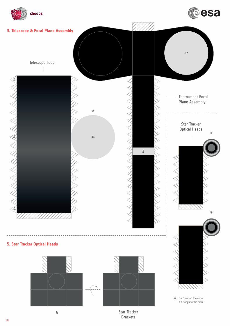
4
4
4
4
Telescope Tube
Instrument Focal Plane Assembly
4
Star TrackerBrackets
Star Tracker Optical Heads
3
5
3. Telescope & Focal Plane Assembly
5. Star Tracker Optical Heads
10
Don’t cut off the circle, it belongs to the piece


7
Solar Arrays
InstrumentRadiators
8
10 10
6. Solar Arrays & Sunshield
9 9
11


sci.esa.int/cheops


![COVID 19 UPDATE [AUTOMOTIVE] · 16.2m 82.5m -8.3% -9.8% -10.7% -8.0% -1.9m —1.4m —1.4m -6.2m 2020 IHS Markit ... MHCV plants in China in many cases extended the lunar New Year](https://img.pdfslide.us/doc/110x75/5ec9197577aaaf6b674551af/covid-19-update-automotive-162m-825m-83-98-107-80-19m-a14m.jpg)