Embed Size (px)
Citation preview
Journal of Engineering Science and Technology Review 12 (3) (2019) 21 - 29
Research Article
Acoustic Emission Characteristics of Corroded Reinforced Concrete Columns under Low-Cyclic Loading
Chen Shaojie*, Ren Jianxi, Li Qiang, Yang Guang and Yan Peilin
School of Architecture and civil engineering, Xi’an University of Science and Technology, Xi’an 710054, China
Received 8 May 2019; Accepted 11 July 2019
___________________________________________________________________________________________ Abstract
Reinforced concrete (RC) columns are important components of architectural structures. Reinforcement corrosion can considerably influence the carrying capacity of concrete columns and seismic performance of the structures. Traditional research methods emphasize on macro-mechanical properties of corroded RC columns. In this study, the entire low-cyclic loading test of corroded RC columns was monitored via acoustic emission (AE) system and its positioning technology to study crack propagation and fracture characteristics during failure of concrete columns. AE ringing counts and energy evolutionary characteristics of corroded RC columns in different loading stages were analysed. Moreover, a low-cyclic loading test damage model of corroded RC columns based on AE ringing counts was constructed, and evolutionary law of internal injuries of columns was explored by the positioning technology. Results demonstrate that AE signals have evident characteristics in different loading stages. The signals are weak before cracking of concrete columns, but suddenly become active in the yielding stage. Signals are most active before peak loads. Degree of concrete column damage at peak loads is positively correlated with corrosion rate of reinforcement, but total released energy and number of AE event in different loading stages are negatively correlated with corrosion rate of reinforcement. 3D positioning results of AE events can intuitively reflect temporal–spatial evolution of internal injuries of concrete columns. The conclusions of this study can provide theoretical references to load-induced internal damage mechanism of corroded concrete columns. Keywords: reinforcement corrosion, concrete columns, low-cyclic loading test, acoustic emission technology ____________________________________________________________________________________________
1. Introduction Columns are important components of structures. Bearing capacity and reliability of reinforced concrete (RC) columns are the key premises for safe service of the structure. These columns can directly influence the overall seismic performance of structures. However, internal reinforcement corrosion easily occurs when the concrete structure is serving in a complicated environment [1]. Studies have proven that reinforcement corrosion is one of the main causes of premature structural failure and poor durability of concrete structure [2]. Reinforcement corrosion in concrete structure is an electrochemical reaction, which is mainly the corrosion reaction of reinforcement in the concrete structure by water and oxygen from the environment [3]. Mechanical properties of the concrete structure are degraded after reinforcement corrosion [4-5]. Moreover, corrosion products pile up surrounding the reinforcement, which causes swelling and cracking of concrete cover. As a result, the concrete structure develops different degrees of damage [6] and its seismic performance is affected [7-8].
Low-cyclic loading test is crucial to the study of earthquake-resistant behavior of structures. This test can evaluate earthquake resistance indexes of RC columns, such as bearing capacity, deformability, and energy dissipation capacity. However, low-cyclic loading test mainly observes
and describes test phenomenon via traditional observation means. The test focuses on mechanical properties of structures but can neither provide real-time monitoring over the entire loading test nor analyze the evolution of internal cracks in concrete structures. Moreover, the low-cyclic loading test cannot disclose the failure mechanism from evolution of internal damages and fractures of materials.
As a nondestructive monitoring technique, AE technology can facilitate real-time monitoring of ongoing failures in materials, collect AE signals, and evaluate structural damages by analyzing parameters [9]. This technology has been widely applied in detection, monitoring, and integrity evaluation of mechanical equipment. Deformation, cracking, crack propagation, and failure of materials are all accompanied by releasing of elastic waves, which is known as AE phenomenon. Elastic waves propagate weak signals from the sound source to the material surface. These signals are received by the sensor and then transmitted to and recorded by the AE system. This technique is called AE technology [10]. AE signals are closely related to stress and strain of concrete materials. Hence, changes in internal injuries of materials could be disclosed by analyzing AE signal parameters.
On this basis, the low-cyclic loading test of corroded RC columns was monitored through the AE system and its positioning technology. The AE signal characteristics and temporal-spatial evolution laws of internal damages of corroded RC columns in different loading stages were analyzed.
JOURNAL OF Engineering Science and Technology Review
www.jestr.org
Jestr
______________ *E-mail address: [email protected] ISSN: 1791-2377 © 2019 Eastern Macedonia and Thrace Institute of Technology. All rights reserved. doi:10.25103/jestr.123.04
Chen Shaojie, Ren Jianxi, Li Qiang, Yang Guang and Yan Peilin/Journal of Engineering Science and Technology Review 12 (3) (2019) 21 - 29
22
2. State of the art Reinforcement corrosion is an important factor that influences the durability of concrete structures. Numerous theoretical and experimental studies on corroded RC components have been reported. However, these studies mainly focus on the degradation of mechanical properties, earthquake resistance, and failure modes of structures after reinforcement corrosion. For example, Kanchanadevi and Ramanjaneyulu [11] conducted low-cyclic loading tests of non-corroded and corroded beam-column joints. They found that the failure mode of structures changed from shear to splitting failure along the corrosion-induced cracks due to corrosion behaviors, and the strength of corrosion samples considerably declined. Fernandez and Herrador [12] corroded four groups of three-span continuous RC beam components through the accelerated corrosion method and conducted a monotonic loading test. They found that ultimate bearing capacity of corroded beams remarkably decreased (up to 55%) compared with that of non-corroded beams. Guo [13] simulated corrosion of pier specimens in the marine environment and analyzed earthquake resistance of specimens with different degrees of corrosion through a cyclic loading test. Results demonstrated that rigidity, strength, ductility, and energy dissipation capacity of specimens were considerably decreased with the increase in corrosion degree. Yalciner and Eren [14] studied influences of mixing ratio, concrete cover thickness, and corrosion rate of reinforcement on bonding strength between reinforcement and concrete. They concluded that specimens with high concrete grade and serious reinforcement corrosion were highly vulnerable to degradation of bonding strength. These studies discussed durability degradation laws of concrete components with reinforcement corrosion from the perspectives of mechanical properties and failure mode. Thus, the experiment must adopt new methods to analyze the internal damage mechanism of concrete components.
Numerous scholars have recently introduced AE technologies into concrete test [15-17]. Ji [18] discussed the application of AE characteristics in the dynamic evaluation of load-induced concrete damages through an experiment. Carpinteri and Lacidogna [19] tested concrete structures based on AE technology. They recorded AE signals during structural injuries and positioned the source of microcracks. Guo [20] conducted AE monitoring over the compression test of concrete specimens with different strength grades and found that concrete strength considerably influenced frequency characteristic parameters of AE signals. Qiu [21] performed a uniaxial compression test to gangue concrete specimens after freezing and thawing based on AE technology, in which compression damages of specimens were studied. Moreover, a damage model was constructed. Based on AE parameters, Fan [22] conducted an experimental study on a three-point bending beam to analyze the ringing counts and energy parameters. Results demonstrated that cracking and buckling loads of the three-point bending beam could be accurately determined through ringing counts and energy curve. Although numerous research works concerning AE characteristics of concrete materials are available, they mainly focus on AE characteristics of concrete specimens during uniaxial compression and loading process of beam components.
However, a few studies on AE characteristics of corroded RC columns under low-cyclic loads are available. Therefore, the damage process of corroded RC columns was monitored by AE technology based on low-cyclic loading
test. Evolutionary law of internal damages was investigated through AE characteristic parameters and its positioning technology. The study conclusions provide theoretical references for load-induced internal damage mechanism of corroded RC columns.
The remainder of this study is organized as follows. Section 3 introduces the low-cyclic loading test of corroded RC columns. Section 4 analyzes AE ringing counts, energy dissipation, and damage positioning results in the low-cyclic loading test of corroded RC columns. Internal damage laws of RC specimens with different degrees of corrosion are discussed. Section 5 summarizes conclusions. 3. Methodology
3.1 Design and Manufacture of Specimens In this test, concrete columns with different rates of reinforcement corrosion were designed. Strength grade of concrete was C30. HPB300 level reinforcement with a diameter of 8 mm was used as stirrups, and six pieces of HRB400 level reinforcements with a diameter of 14 mm were applied as longitudinal bars of columns. Longitudinal bars at the base bottom used six pieces of HRB400 level reinforcement with a diameter of 16 mm. The column and base covering layers were 15 and 30 mm thick, respectively. Sectional size and reinforcement of RC columns are shown in Fig. 1.
Fig. 1. Size and reinforcement of concrete columns
Based on the principle of electrochemical corrosion, reinforcement corrosion was artificially simulated through saline soaking of concrete columns and impressing an anodic current on reinforcement. A total of 5% cement mass of NaCl was added into concrete during specimen preparation to accelerate passive film failure on the reinforcement surface and obtain an accurate corrosion rate [23]. At the end of maintenance, electricity was supplied to 5% NaCl solution to accelerate reinforcement corrosion. Different corrosion rates of reinforcement were simulated by controlling power-on hours [24].
After finishing the test, concrete was broken into pieces and internal reinforcement was collected to test the rate of reinforcement corrosion. Concretes that adhered on reinforcement were eliminated. The reinforcement was washed by 12% hydrochloric acids first and rinsed with clean water, followed by drying and weighing [25]. Corrosion rates were calculated according to Eq. (1). The average corrosion rates of specimens are shown in Table 1.
(1) where is the corrosion rate of reinforcement, is the mass of equal long non-corroded reinforcement in the same batch, and is the mass of corroded reinforcement after rust removal.
0 0( ) / 100%xm m mh = - ´
h 0m
xm
Chen Shaojie, Ren Jianxi, Li Qiang, Yang Guang and Yan Peilin/Journal of Engineering Science and Technology Review 12 (3) (2019) 21 - 29
23
Table. 1. Rate of reinforcement corrosion Specimen
No. Designed corrosion
rate /% Actual average corrosion
rate /% Z1 0 0 Z2 5 5.33 Z3 10 12.11 Z4 15 16.88
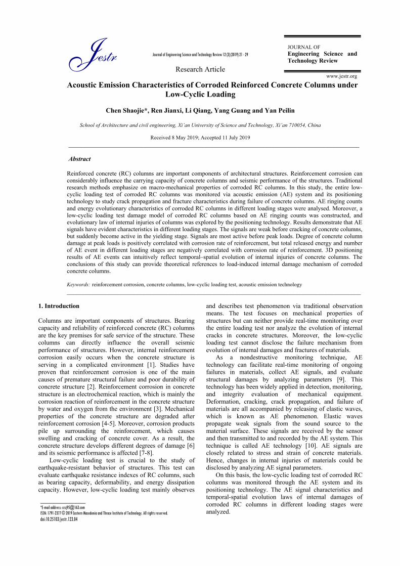
3.2 Experimental apparatus and schemes 3.2.1 Experimental apparatus The horizontal loading was accomplished by MTS201.60A actuator with a maximum output load of 1000 kN. The maximum output load of the vertical hydraulic jack was 2000 kN. TDS-630 of Japan Tokyo Institute of Measurement Instrument was applied to record displacement of concrete columns and strain of reinforcement. The Micro-II Express test system of Physical Acoustics Corporation (USA), which is equipped with a piece of express card involving eight AE channels, was used for AE. Real-time collection of AE parameters and waveform flow could be realized by this system. The experimental apparatus is shown in Fig. 2.
Fig. 2. Experimental apparatus 3.2.2 Experimental scheme (1) Loading scheme Load-deformation combined control method was applied in the loading process. First, a 200 kN axial force was applied to specimens by using a vertical jack, which was maintained constant throughout the entire test. Acyclic horizontal loading process was then implemented at the designed height of columns by using an MTS horizontal actuator (Fig. 3). According to regulations of the seismic test method of architectures [26], staged loading was applied before yielding of specimens, and each level of loads had one cycle. After the yielding of specimens, the horizontal displacement at the top loading point of longitudinal reinforcement yielding at the bottom was used as the range Δ. Three cycles were set to each level of loads during displacement-controlled loading. The loading process was finally terminated when loads decreased to 85% of peak loads.
Fig. 3. Horizontal loading system
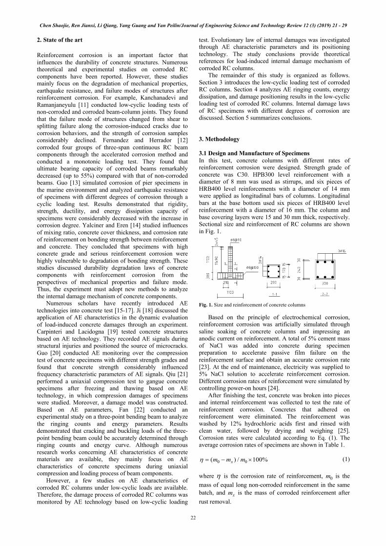
(2) AE parameters and distribution of measuring points In this experiment, Express-8 test system with eight channels was applied for AE monitoring. Piezoelectric sensors (R15α), 100 to 400 kHz filters, and 40 dB pre-amplification gains were applied. Before the experiment, threshold value was set to 40 dB according to in-situ lead breaking test. Column specimens were designed 1100 mm high. Given that column failure mainly occurs at the plastic hinge zone, AE positioning mainly tested injuries in 500 mm of column base. Sensor distribution is shown in Fig. 4. Before distribution of sensors, the surface at different measuring points must be polished until smooth and then coated with Vaseline and fixed with packaging tape.
Fig. 4. Distribution of sensors 4 Result Analysis and Discussion 4.1AE characteristics of corroded RC columns AE signals can be divided into continuous and outburst types. If an AE signal is inseparable in time and is produced by simultaneous occurrence of abundant events, then this signal is a continuous signal. If an AE signal is separable in time, then it is an outburst signal [10]. Fig. 5 shows waveform of outburst AE signal, which reflects amplitude, threshold value, rise time, and duration. The ringing counts are the number of oscillation when AE signal crosses over the threshold. Energy is the area under the signal detection envelope.
Fig. 5. Waveform parameters of AE signals Concrete columns have experienced cracking, yielding, peak loads, and failure process in the loading process. In the test, all specimens have similar AE characteristics in different stages but demonstrated varying corrosion rate. AE ringing counts are the number of oscillations when AE signals crosses over the threshold. They can reflect intensity
Chen Shaojie, Ren Jianxi, Li Qiang, Yang Guang and Yan Peilin/Journal of Engineering Science and Technology Review 12 (3) (2019) 21 - 29
24
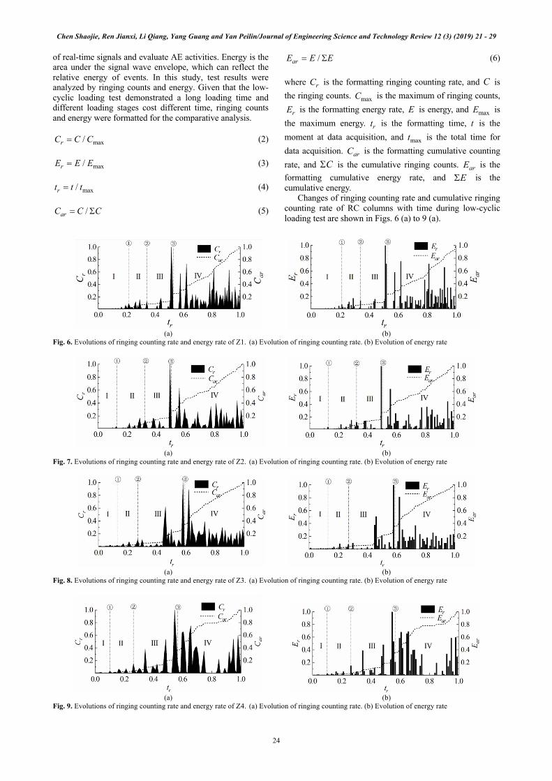
of real-time signals and evaluate AE activities. Energy is the area under the signal wave envelope, which can reflect the relative energy of events. In this study, test results were analyzed by ringing counts and energy. Given that the low-cyclic loading test demonstrated a long loading time and different loading stages cost different time, ringing counts and energy were formatted for the comparative analysis.
(2)
(3)
(4)
(5)
(6) where is the formatting ringing counting rate, and is the ringing counts. is the maximum of ringing counts,
is the formatting energy rate, is energy, and is the maximum energy. is the formatting time, is the moment at data acquisition, and is the total time for data acquisition. is the formatting cumulative counting rate, and is the cumulative ringing counts. is the formatting cumulative energy rate, and is the cumulative energy.
Changes of ringing counting rate and cumulative ringing counting rate of RC columns with time during low-cyclic loading test are shown in Figs. 6 (a) to 9 (a).
(a) (b)
Fig. 6. Evolutions of ringing counting rate and energy rate of Z1. (a) Evolution of ringing counting rate. (b) Evolution of energy rate
(a) (b)
Fig. 7. Evolutions of ringing counting rate and energy rate of Z2. (a) Evolution of ringing counting rate. (b) Evolution of energy rate
(a) (b)
Fig. 8. Evolutions of ringing counting rate and energy rate of Z3. (a) Evolution of ringing counting rate. (b) Evolution of energy rate
(a) (b)
Fig. 9. Evolutions of ringing counting rate and energy rate of Z4. (a) Evolution of ringing counting rate. (b) Evolution of energy rate
max/rC C C=
max/rE E E=
max/rt t t=
/arC C C= S
/arE E E= S
rC C
maxC
rE E maxE
rt t
maxt
arCCS arE
ES
Chen Shaojie, Ren Jianxi, Li Qiang, Yang Guang and Yan Peilin/Journal of Engineering Science and Technology Review 12 (3) (2019) 21 - 29
25
Changes of energy rate and cumulative energy rate of RC columns with time during low-cyclic loading test are shown in Figs. 6 (b) to 9 (b). Specifically, ① to ③ are points for cracking, yielding, and peak load of RC columns. Ringing counting rate of RC columns evidently shows the basic similar variation law with energy rate. Moreover, the increasing trend of cumulative ringing counting rate is consistent with that of cumulative energy rate. AE ringing counting rate and energy rate signals have evident characteristics at cracking and yielding of RC columns. AE signals are weak and are almost zero prior to cracking. Faint signals of ringing counting rate and energy rate are observed at cracking. The AE signals of specimens are weak from cracking to yielding, thereby reflecting the small injuries of materials and low amplitudes of cumulative ringing counting rate and cumulative energy rate in the early development stage of defects. The activation of AE signals begins in the yielding stage, and evident signal jumps are observed. AE signals are gradually strengthened from the yield load ② to the peak load ③ , reaching the peak after several jumps. These signals reflect the development and continuous propagation of injuries in RC columns. A displacement-controlled low-cyclic loading is applied in this stage. Therefore, sudden changes of ringing counting rate and energy rate mainly occur at the first cycle of actuator and tensile crack initiation in concretes. Moreover, AE ringing counts and energy are still produced at the second and third cycles of closing or re-opening of concrete cracks. However, the signal values are smaller than those in the first cycle. In the deformation-controlled loading stage, variation laws of ringing counting rate and cumulative energy rate evidently show a staged rising trend. RC columns also develop nonlinear damage characteristics.
During the loading process, RC columns experience crack initiation, propagation, and final failure. Kachanov [27] proposed a damage variable (D) to analyze evolution law of material injuries:
(7) where is the degree of material damages, is the sectional area on the damaged bearing surface, and is the sectional area under zero damage.
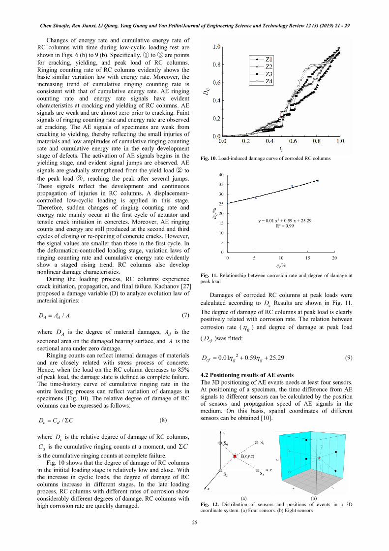
Ringing counts can reflect internal damages of materials and are closely related with stress process of concrete. Hence, when the load on the RC column decreases to 85% of peak load, the damage state is defined as complete failure. The time-history curve of cumulative ringing rate in the entire loading process can reflect variation of damages in specimens (Fig. 10). The relative degree of damage of RC columns can be expressed as follows:
(8) where is the relative degree of damage of RC columns,
is the cumulative ringing counts at a moment, and is the cumulative ringing counts at complete failure.
Fig. 10 shows that the degree of damage of RC columns in the initital loading stage is relatively low and close. With the increase in cyclic loads, the degree of damage of RC columns increase in different stages. In the late loading process, RC columns with different rates of corrosion show considerably different degrees of damage. RC columns with high corrosion rate are quickly damaged.
Fig. 10. Load-induced damage curve of corroded RC columns
Fig. 11. Relationship between corrosion rate and degree of damage at peak load
Damages of corroded RC columns at peak loads were calculated according to Results are shown in Fig. 11. The degree of damage of RC columns at peak load is clearly positively related with corrosion rate. The relation between corrosion rate ( ) and degree of damage at peak load
( )was fitted:
(9) 4.2 Positioning results of AE events The 3D positioning of AE events needs at least four sensors. At positioning of a specimen, the time difference from AE signals to different sensors can be calculated by the position of sensors and propagation speed of AE signals in the medium. On this basis, spatial coordinates of different sensors can be obtained [10].
(a) (b)
Fig. 12. Distribution of sensors and positions of events in a 3D coordinate system. (a) Four sensors. (b) Eight sensors
/A dD A A=
AD dAA
/c dD C C= S
cD
dC CS
y = 0.01 x2 + 0.59 x + 25.29 R² = 0.99
0
5
10
15
20
25
30
35
40
0 5 10 15 20
Dcf
/%
ηg/%
cD
gh
cfD
20.01 0.59 25.29cf g gD h h= + +
Chen Shaojie, Ren Jianxi, Li Qiang, Yang Guang and Yan Peilin/Journal of Engineering Science and Technology Review 12 (3) (2019) 21 - 29
26
In Fig. 12(a), E is supposed to be the position of one AE event and S0–S3 are AE sensors. The coordinates of four sensors are , , , and . The AE event is and its propagation speed in medium is . Therefore, , , , and respectively facilitates the propagation of the event
to , , , and , and the propagation distance between event and the four sensors ( , , , and
) is , , , and .
(10)
(11)
(12)
(13)
Then, the time difference when different sensors receive the AE signals is:
(14)
(15)
(16)
In Eqs. (10)-(13), , , and are unknown variables. The coordinate of point E could be calculated by introducing
, , , and into Eqs. (14)-(16). Hence, at least four sensors are needed in 3D positioning to calculate coordinates of the event. If multiple sensors are added, then the acquisition software determines the most accurate coordinate of an event through the principle of multiple regressions.
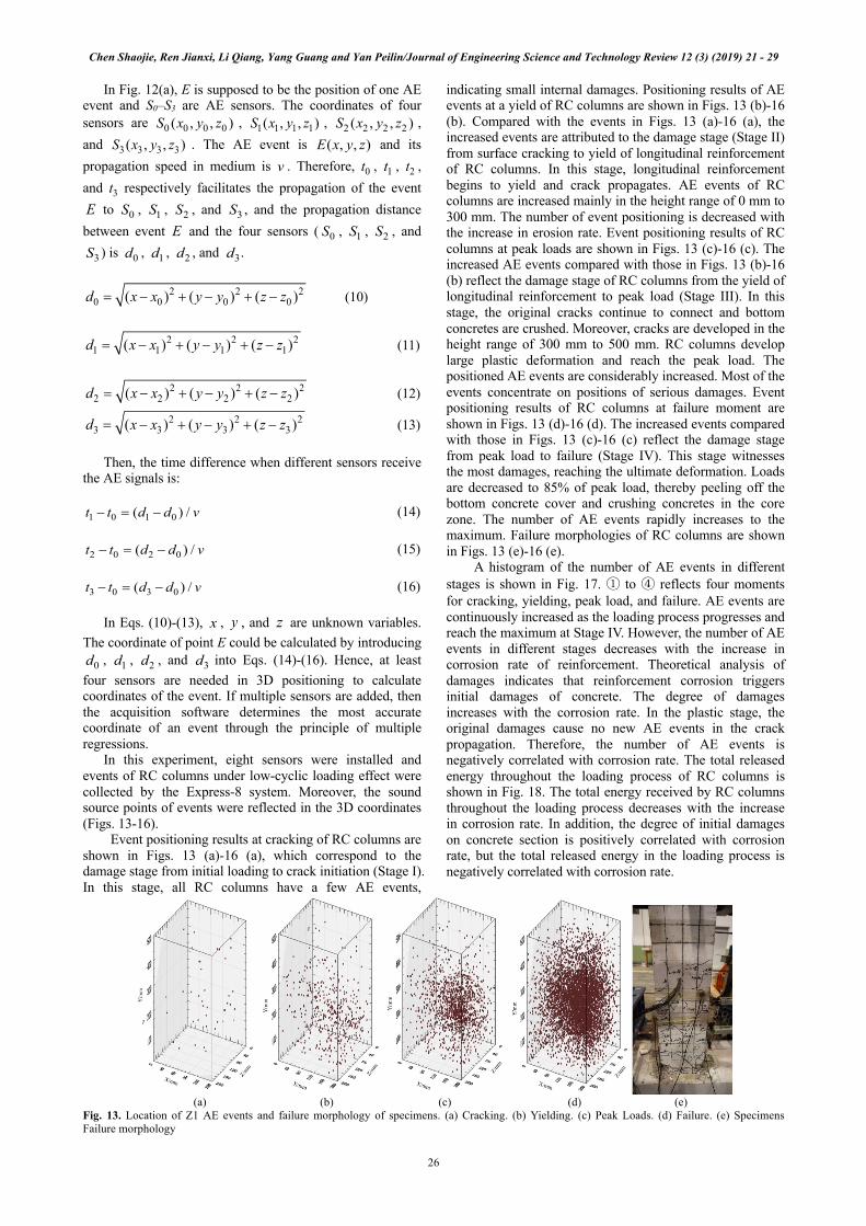
In this experiment, eight sensors were installed and events of RC columns under low-cyclic loading effect were collected by the Express-8 system. Moreover, the sound source points of events were reflected in the 3D coordinates (Figs. 13-16).
Event positioning results at cracking of RC columns are shown in Figs. 13 (a)-16 (a), which correspond to the damage stage from initial loading to crack initiation (Stage I). In this stage, all RC columns have a few AE events,
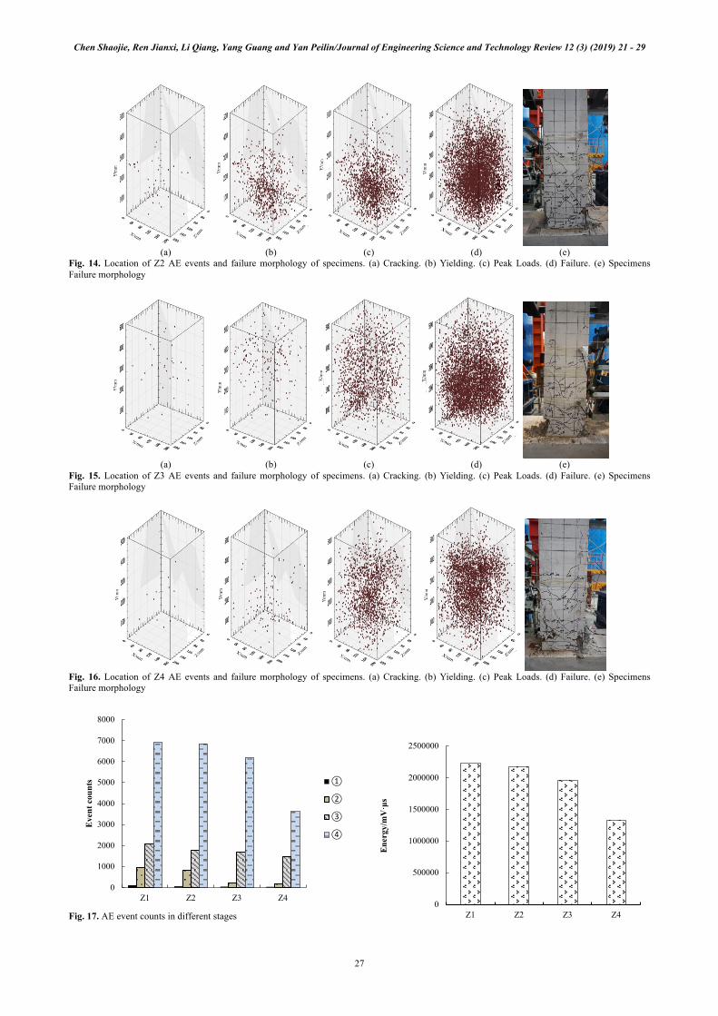
indicating small internal damages. Positioning results of AE events at a yield of RC columns are shown in Figs. 13 (b)-16 (b). Compared with the events in Figs. 13 (a)-16 (a), the increased events are attributed to the damage stage (Stage II) from surface cracking to yield of longitudinal reinforcement of RC columns. In this stage, longitudinal reinforcement begins to yield and crack propagates. AE events of RC columns are increased mainly in the height range of 0 mm to 300 mm. The number of event positioning is decreased with the increase in erosion rate. Event positioning results of RC columns at peak loads are shown in Figs. 13 (c)-16 (c). The increased AE events compared with those in Figs. 13 (b)-16 (b) reflect the damage stage of RC columns from the yield of longitudinal reinforcement to peak load (Stage III). In this stage, the original cracks continue to connect and bottom concretes are crushed. Moreover, cracks are developed in the height range of 300 mm to 500 mm. RC columns develop large plastic deformation and reach the peak load. The positioned AE events are considerably increased. Most of the events concentrate on positions of serious damages. Event positioning results of RC columns at failure moment are shown in Figs. 13 (d)-16 (d). The increased events compared with those in Figs. 13 (c)-16 (c) reflect the damage stage from peak load to failure (Stage IV). This stage witnesses the most damages, reaching the ultimate deformation. Loads are decreased to 85% of peak load, thereby peeling off the bottom concrete cover and crushing concretes in the core zone. The number of AE events rapidly increases to the maximum. Failure morphologies of RC columns are shown in Figs. 13 (e)-16 (e).
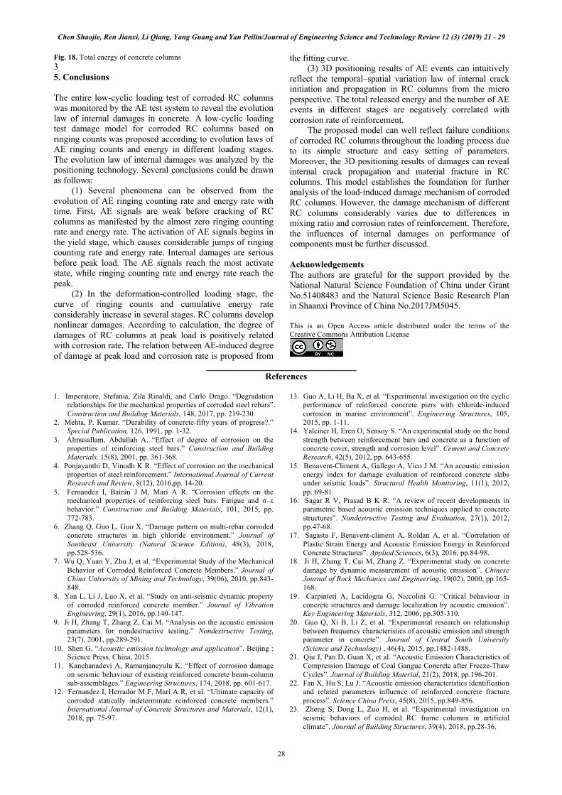
A histogram of the number of AE events in different stages is shown in Fig. 17. ① to ④ reflects four moments for cracking, yielding, peak load, and failure. AE events are continuously increased as the loading process progresses and reach the maximum at Stage IV. However, the number of AE events in different stages decreases with the increase in corrosion rate of reinforcement. Theoretical analysis of damages indicates that reinforcement corrosion triggers initial damages of concrete. The degree of damages increases with the corrosion rate. In the plastic stage, the original damages cause no new AE events in the crack propagation. Therefore, the number of AE events is negatively correlated with corrosion rate. The total released energy throughout the loading process of RC columns is shown in Fig. 18. The total energy received by RC columns throughout the loading process decreases with the increase in corrosion rate. In addition, the degree of initial damages on concrete section is positively correlated with corrosion rate, but the total released energy in the loading process is negatively correlated with corrosion rate.
(a) (b) (c) (d) (e)
Fig. 13. Location of Z1 AE events and failure morphology of specimens. (a) Cracking. (b) Yielding. (c) Peak Loads. (d) Failure. (e) Specimens Failure morphology
0 0 0 0( , , )S x y z 1 1 1 1( , , )S x y z 2 2 2 2( , , )S x y z
3 3 3 3( , , )S x y z ( , , )E x y zv 0t 1t 2t
3tE 0S 1S 2S 3S
E 0S 1S 2S
3S 0d 1d 2d 3d
2 2 20 0 0 0( ) ( ) ( )d x x y y z z= - + - + -
2 2 21 1 1 1( ) ( ) ( )d x x y y z z= - + - + -
2 2 22 2 2 2( ) ( ) ( )d x x y y z z= - + - + -
2 2 23 3 3 3( ) ( ) ( )d x x y y z z= - + - + -
1 0 1 0( ) /t t d d v- = -
2 0 2 0( ) /t t d d v- = -
3 0 3 0( ) /t t d d v- = -
x y z
0d 1d 2d 3d
Chen Shaojie, Ren Jianxi, Li Qiang, Yang Guang and Yan Peilin/Journal of Engineering Science and Technology Review 12 (3) (2019) 21 - 29
27
(a) (b) (c) (d) (e)
Fig. 14. Location of Z2 AE events and failure morphology of specimens. (a) Cracking. (b) Yielding. (c) Peak Loads. (d) Failure. (e) Specimens Failure morphology
(a) (b) (c) (d) (e)
Fig. 15. Location of Z3 AE events and failure morphology of specimens. (a) Cracking. (b) Yielding. (c) Peak Loads. (d) Failure. (e) Specimens Failure morphology
Fig. 16. Location of Z4 AE events and failure morphology of specimens. (a) Cracking. (b) Yielding. (c) Peak Loads. (d) Failure. (e) Specimens Failure morphology
Fig. 17. AE event counts in different stages
0
1000
2000
3000
4000
5000
6000
7000
8000
Z1 Z2 Z3 Z4
Eve
nt c
ount
s ①
②
③
④
0
500000
1000000
1500000
2000000
2500000
Z1 Z2 Z3 Z4
Ene
rgy/
mV
·μs
Chen Shaojie, Ren Jianxi, Li Qiang, Yang Guang and Yan Peilin/Journal of Engineering Science and Technology Review 12 (3) (2019) 21 - 29
28
Fig. 18. Total energy of concrete columns 3 5. Conclusions The entire low-cyclic loading test of corroded RC columns was monitored by the AE test system to reveal the evolution law of internal damages in concrete. A low-cyclic loading test damage model for corroded RC columns based on ringing counts was proposed according to evolution laws of AE ringing counts and energy in different loading stages. The evolution law of internal damages was analyzed by the positioning technology. Several conclusions could be drawn as follows:
(1) Several phenomena can be observed from the evolution of AE ringing counting rate and energy rate with time. First, AE signals are weak before cracking of RC columns as manifested by the almost zero ringing counting rate and energy rate. The activation of AE signals begins in the yield stage, which causes considerable jumps of ringing counting rate and energy rate. Internal damages are serious before peak load. The AE signals reach the most activate state, while ringing counting rate and energy rate reach the peak.
(2) In the deformation-controlled loading stage, the curve of ringing counts and cumulative energy rate considerably increase in several stages. RC columns develop nonlinear damages. According to calculation, the degree of damages of RC columns at peak load is positively related with corrosion rate. The relation between AE-induced degree of damage at peak load and corrosion rate is proposed from
the fitting curve. (3) 3D positioning results of AE events can intuitively
reflect the temporal–spatial variation law of internal crack initiation and propagation in RC columns from the micro perspective. The total released energy and the number of AE events in different stages are negatively correlated with corrosion rate of reinforcement.
The proposed model can well reflect failure conditions of corroded RC columns throughout the loading process due to its simple structure and easy setting of parameters. Moreover, the 3D positioning results of damages can reveal internal crack propagation and material fracture in RC columns. This model establishes the foundation for further analysis of the load-induced damage mechanism of corroded RC columns. However, the damage mechanism of different RC columns considerably varies due to differences in mixing ratio and corrosion rates of reinforcement. Therefore, the influences of internal damages on performance of components must be further discussed. Acknowledgements The authors are grateful for the support provided by the National Natural Science Foundation of China under Grant No.51408483 and the Natural Science Basic Research Plan in Shaanxi Province of China No.2017JM5045. This is an Open Access article distributed under the terms of the Creative Commons Attribution License
______________________________
References 1. Imperatore, Stefania, Zila Rinaldi, and Carlo Drago. “Degradation
relationships for the mechanical properties of corroded steel rebars”. Construction and Building Materials, 148, 2017, pp. 219-230.
2. Mehta, P. Kumar. “Durability of concrete-fifty years of progress?.” Special Publication, 126, 1991, pp. 1-32.
3. Almusallam, Abdullah A. “Effect of degree of corrosion on the properties of reinforcing steel bars.” Construction and Building Materials, 15(8), 2001, pp. 361-368.
4. Ponjayanthi D, Vinodh K R. “Effect of corrosion on the mechanical properties of steel reinforcement.” International Journal of Current Research and Review, 8(12), 2016,pp. 14-20.
5. Fernandez I, Bairán J M, Marí A R. “Corrosion effects on the mechanical properties of reinforcing steel bars. Fatigue and σ–ε behavior.” Construction and Building Materials, 101, 2015, pp. 772-783.
6. Zhang Q, Guo L, Guo X. “Damage pattern on multi-rebar corroded concrete structures in high chloride environment.” Journal of Southeast University (Natural Science Edition), 48(3), 2018, pp.528-536.
7. Wu Q, Yuan Y, Zhu J, et al. “Experimental Study of the Mechanical Behavior of Corroded Reinforced Concrete Members.” Journal of China University of Mining and Technology, 39(06), 2010, pp.843-848.
8. Yan L, Li J, Luo X, et al. “Study on anti-seismic dynamic property of corroded reinforced concrete member.” Journal of Vibration Engineering, 29(1), 2016, pp.140-147.
9. Ji H, Zhang T, Zhang Z, Cai M. “Analysis on the acoustic emission parameters for nondestructive testing.” Nondestructive Testing, 23(7), 2001, pp.289-291.
10. Shen G. “Acoustic emission technology and application”. Beijing : Science Press, China, 2015.
11. Kanchanadevi A, Ramanjaneyulu K. “Effect of corrosion damage on seismic behaviour of existing reinforced concrete beam-column sub-assemblages.” Engineering Structures, 174, 2018, pp. 601-617.
12. Fernandez I, Herrador M F, Marí A R, et al. “Ultimate capacity of corroded statically indeterminate reinforced concrete members.” International Journal of Concrete Structures and Materials, 12(1), 2018, pp. 75-97.
13. Guo A, Li H, Ba X, et al. “Experimental investigation on the cyclic performance of reinforced concrete piers with chloride-induced corrosion in marine environment”. Engineering Structures, 105, 2015, pp. 1-11.
14. Yalciner H, Eren O, Sensoy S. “An experimental study on the bond strength between reinforcement bars and concrete as a function of concrete cover, strength and corrosion level”. Cement and Concrete Research, 42(5), 2012, pp. 643-655.
15. Benavent-Climent A, Gallego A, Vico J M. “An acoustic emission energy index for damage evaluation of reinforced concrete slabs under seismic loads”. Structural Health Monitoring, 11(1), 2012, pp. 69-81.
16. Sagar R V, Prasad B K R. “A review of recent developments in parametric based acoustic emission techniques applied to concrete structures”. Nondestructive Testing and Evaluation, 27(1), 2012, pp.47-68.
17. Sagasta F, Benavent-climent A, Roldan A, et al. “Correlation of Plastic Strain Energy and Acoustic Emission Energy in Reinforced Concrete Structures”. Applied Sciences, 6(3), 2016, pp.84-98.
18. Ji H, Zhang T, Cai M, Zhang Z. “Experimental study on concrete damage by dynamic measurement of acoustic emission”. Chinese Journal of Rock Mechanics and Engineering, 19(02), 2000, pp.165-168.
19. Carpinteri A, Lacidogna G, Niccolini G. “Critical behaviour in concrete structures and damage localization by acoustic emission”. Key Engineering Materials, 312, 2006, pp.305-310.
20. Guo Q, Xi B, Li Z, et al. “Experimental research on relationship between frequency characteristics of acoustic emission and strength parameter in concrete”. Journal of Central South University (Science and Technology) , 46(4), 2015, pp.1482-1488.
21. Qiu J, Pan D, Guan X, et al. “Acoustic Emission Characteristics of Compression Damage of Coal Gangue Concrete after Freeze-Thaw Cycles”. Journal of Building Material, 21(2), 2018, pp.196-201.
22. Fan X, Hu S, Lu J. “Acoustic emission characteristics identification and related parameters influence of reinforced concrete fracture process”. Science China Press, 45(8), 2015, pp.849-856.
23. Zheng S, Dong L, Zuo H, et al. “Experimental investigation on seismic behaviors of corroded RC frame columns in artificial climate”. Journal of Building Structures, 39(4), 2018, pp.28-36.
Chen Shaojie, Ren Jianxi, Li Qiang, Yang Guang and Yan Peilin/Journal of Engineering Science and Technology Review 12 (3) (2019) 21 - 29
29
24. Yuan Y, Zhang X, Ji Y. “A comparative study on structural behavior of deteriorated reinforced concrete beam under two different environments”. China Civil Engineering Journal, 39(3), 2006, pp.42-46.
25. GB/T50082-2009, “Standard for test methods of long-term performance and durability of ordinary concrete,” Beijing: China Architecture and Building Press, China, 2009.
26. JGJ101-2015, “Specification of test methods for earthquake resistant building,” Beijing: China Architecture and Building Press, China,2015.
27. Kachanov L M. “Rupture Time Under Creep Conditions”. International Journal of Fracture, 97(1-4), 1999, pp.11-18.


![Ching-Wei Cheng Guang Cheng arXiv:1906.02389v1 [math.ST] 6 ... · Enhancing Multi-model Inference with Natural Selection Ching-Wei Cheng Guang Chengy Abstract Multi](https://img.pdfslide.us/doc/110x75/5fc18060045d79754671aac5/ching-wei-cheng-guang-cheng-arxiv190602389v1-mathst-6-enhancing-multi-model.jpg)