Embed Size (px)
Citation preview
CHEMISTRY AND SURFACE TREATMENT
D. Bloess
CERN, Geneva, Switzerland
1. INTRODUCTION
What is new in surface treatment of Nb cavities since the last
workshop in 19801 If one asks this question one has at first the
impression that no real progress has been made. The recent increase in
field obtained, is certainely not due to a better surface treatment, but
to a better bulk material, that is, a higher thermal conductivity. The
maximum obtained Q-value is not superior to what has already been published
long time ago and there are very few new treatment methods: the abrasive
tumbling at DESY and the ultraviolet light-oxygen treatment at Orsay.
However, at a more detailed examination one discovers in fact quite a
substantial improvement.
A few years ago, when a laboratory obtained good results, other
laboratories just copied their treatment methods, assuming, that the key
for the sucess must lie in those specific methods. Today one has much
better understood what is necessary for obtaining adequate surfaces. Now
laboratories develop all their own sequence of surface treatments, well
optimized to their specific requirements, which depend on the means
available, the frequency, the shape and the size of their cavities and the
number of cavities to be built.
The results obtained a few years ago were in general at first rather
moderate and improved only after a number of cycles of mechanical rework
of bad spots, chemical treatment, and new measurement. Today, results are
good typically already after the first cool-down.
Proceedings of SRF Workshop 1984, Geneva, Switzerland SRF84-23
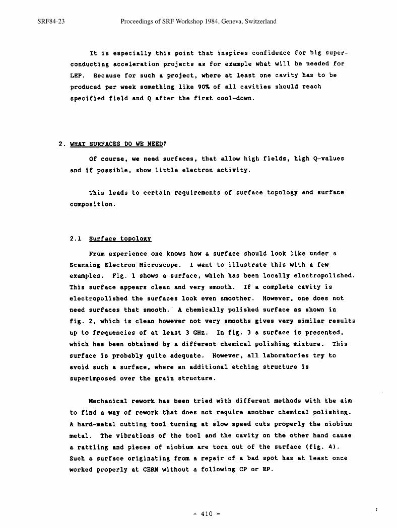
It is especially this point that inspires confidence for big super-
conducting acceleration projects as for example what will be needed for
LEP. Because for such a project, where at least one cavity has to be
produced per week something like 90% of all cavities should reach
specified field and Q after the first cool-down.
2. WHAT SURFACES DO WE NEED?
Of course, we need surfaces, that allow high fields, high Q-values
and if possible, show little electron activity.
This leads to certain requirements of surface topology and surface
composition.
2.1 Surface to~olonv
From experience one knows how a surface should look like under a
Scanning Electron Microscope. I want to illustrate this with a few
examples. Fig. 1 shows a surface, which has been locally electropolished.
This surface appears clean and very smooth. If a complete cavity is
electropolished the surfaces look even smoother. However, one does not
need surfaces that smooth. A chemically polished surface as shown in
fig. 2, which is clean however not very smooths gives very similar results
up to frequencies of at least 3 GHz. In fig. 3 a surface is presented,
which has been obtained by a different chemical polishing mixture. This
surface is probably quite adequate. However, all laboratories try to
avoid such a surface, where an additional etching structure is
superimposed over the grain structure.
Mechanical rework has been tried with different methods with the aim
to find a way of rework that does not require another chemical polishing.
A hard-metal cutting tool turning at slow speed cuts properly the niobium
metal. The vibrations of the tool and the cavity on the other hand cause
a rattling and pieces of niobium are torn out of the surface (fig. 4 ) .
Such a surface originating from a repair of a bad spot has at least once
worked properly at CERN without a following CP or EP.
SRF84-23 Proceedings of SRF Workshop 1984, Geneva, Switzerland
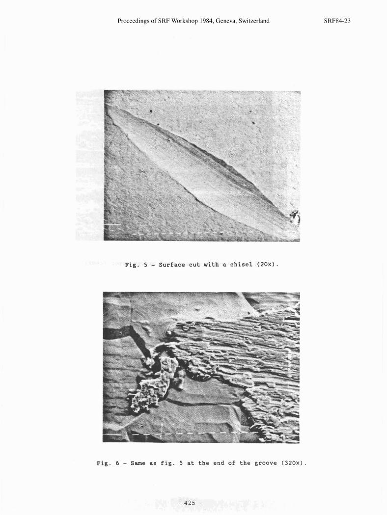
If one wants to take the bad point out in one piece with a chisel for
further analysis one gets a surface which looks smoothly cut at first view
(fig. 5 ) . But at the edges of this groove niobium is smeared over the
surface (fig. 6 ) . This leads to a quench in CLEW cavities at low fields
(typ. 1-2 MeV/m). The same is true, if one uses a hard-metal hand-tool
turning at high speed (dentist's turbine drill). In this case no rattling
occurs, but the niobium is not cut properly and smeared over the surface.
Reworking done with emery paper leads to a very contaminated surface.
Abrasive material is pushed into the niobium (fig. 7). Thus, a chemical
or electrochemical polishing of at least 20 pm has to be done.
2.2 Surface com~osition
Many studies have been done on the influence of different surface
compositions, especially oxyde layers, on r.f. superconductivity.
Unfortunately only very few observations of the surface composition of
actual cavities have been done, and their correlation to cavity performance
evaluated. What can be found on a surface is shown in tables 1 and 2.
Samples 1 and 2 have been obtained from the CERN 5-cell 500 MHz
cavity, which has operated in PETRA at DESY. The reference sample has
been treated separately in the CERN chemical laboratory. In all three
cases analytical grade etching mixtures and high purity demineralized
water have been used. Surface analysis with SIMS shows at a depth of
10 A an impressive number of foreign elements are found in considerable
quantities (table 1). In table 2 one can see that lead further increases
near the surface.
The origin of this contamination and its influence on cavity
performance are unknown. It is also unknown whether these surfaces are
"normal" in CERN cavities or whether this was an exceptional accident.
More analytical studies will have to be done.
Proceedings of SRF Workshop 1984, Geneva, Switzerland SRF84-23
3. HOW TO OBTAIN RELIABLY GOOD SURFACES
In general there are always the same procedures, with a different
emphasis though, at each step during production: inspection, mechanical
rework, chemical or electrochemical polishing and rising.
3.1 Inspection
Especially large low frequency cavities ask for meticulous inspection
of squaremetres of surface and metres of welds. Defects bigger than, say
10 pm, which are not detected can produce bad performance of a cavity.
Up till now no automatic instrument has been developed to help in
this difficult task. Everybody is relying on the skill of a well-trained
technician, scanning the surfaces with their eyes and finding with their
finger tips welding beads or sharp edges on the welds. Suspected areas
are then looked at with a magnifying glass or a telescope.
A microscope at the end of a manipulator arm approached to the surface
can reveal topological details, which are lost if one is using a telescope.
For this reason the development of such a device has been started at CERN.
Smooth mirrorlike surfaces and welds allow a more efficient inspection than
the "orange skin" surface obtained with chemical polishing.
3.2 Rework
Depending on the size and nature of the defect, rework is done either
with a hard-metal tool (dentist's drill) or/and with emery paper.
For multicell cavities the access to all parts of the cavity becomes
impossible. Therefore, one is developing at Cornell [l] and at CERN a
numerical controlled manipulator, which allows a tool to be brought to the
region of the defect. Because of vibrations of the manipulator arm and
cavity, it is however not easy to produce a smooth milling or grinding of
the defect area.
SRF84-23 Proceedings of SRF Workshop 1984, Geneva, Switzerland
Successful tests have been done at CERN with a local electropolishing.
A jet of a modified electropolishing mixture (hydrofluoric acid, sulfuric
acid and phosphoric acid) is directed through a niobium nozzle on to the
defect [21 . The nozzle is connected as cathode and the cavity as anode.
Up till now, however, it was not possible to avoid some hydrogen of
reaching the cavity surface. Despite this hydrogen contamination an
acceleration field of 8 MeV/m has been reached in one of our 500 HHz
cavities and the locally electropolished spots (one at the equator and one
near the iris) did not show up on the temperature map.
Clean surfaces are obtained by chemical or electro-chemical
polishing. Niobium is not a very nobel metal and the freshly polished
surface is highly reactive. It is therefore important to use high purity
analytical grade chemicals and for the subsequent rinsing well demi-
neralized high resistivity water. Otherwise more noble metal ions can be
chemically deposited on the surface. This is not possible with electro-
chemical polishing as long as current flows. But it should even be more
pronounced once the current is being switched off.
With EP one gets very smooth mirrorlike surfaces [ 3 ] . These surfaces
were expected:
(a) To produce less field emission. Comparing the results of different
laboratories, this effect is doubtful 141, [15].
(b) To have a higher Q because the surface is smaller. Evaluating the
test results with a 350 W z cavity at CERN, it is evident that the
difference between a CP surface and an ideal (EP) surface is rather
small [161.
(c) To facilitate recognition of defects on the surface. To my opinion
this is the most important advantage of EP.
(d) To avoid a chemical run-away reaction, which is the big danger of CP.
But EP has a number of disadvantages, which has led more and more
laboratories to abandon this method:
Proceedings of SRF Workshop 1984, Geneva, Switzerland SRF84-23
(a) EP is slow. The 40 pm/h given by Siemens is even optimistic,
because the process has frequently to be stopped, the mixture pumped
and the hydrogen gas removed. At Saclay one needs 48 h for the
polishing of one of their helix-type cavities [141.
(b) The niobium surfaces have to be protected from the developing hydrogen
gas. At KEK this is accomplished with a porous teflon membrane
around the cathode [41. Dornier in Germany announced that they have
developed a new electrolyte, which works without the development of
hydrogen gas. However, no details were given.
(c) A current density of - 10' M m 2 must be maintained over the
entire surface in order to have good electropolishing. This is
difficult or even impossible for complicated cavity shapes [141.
This current at a voltage of 10-15 V dissipates 10-15 kw/m2, which
as to be cooled away.
(d) The surface gets contaminated with the reduction products (H2S and S )
of sulfuric acid and has to be cleaned with a hydrogen peroxyde
solution.
3.4 Chemical polishing (CP)
Also with CP one can obtain very smooth surfaces by using a mixture of
concentrated hydrofluoric acid and nitric acid in a ratio of 1:l. The
speed of this reaction is very fast (30 s for 60 pm). Therefore, it can
only be used for small cavities. Slowing down of the reaction can be done
by the addition of phosphoric acid. The most frequently used mixture
(standard mixture) consists of equal volumes of hydrofluoric acid (48%),
nitric acid (65%) and phosphoric acid (d = 1.7). At a temperature of 25°C
this mixture dissolves 4-6 pm/min of niobium from the surface. However:
(a) The surface is not very smooth (orange skin). This does not strongly
influence the performance of the cavity, but it is definitively an
obstacle for the detection of defects.
(b) Despite the slowing down of the reaction, it is still strongly
positively temperature dependent and exothermic, which means it has
the tendency of run-away. Therefore, great care has to be taken in
the design of the CP equipment. It must be possible under all
circumstances to drain rapidly the acid mixture from the cavity,
especially if great volumes of acid are used.
SRF84-23 Proceedings of SRF Workshop 1984, Geneva, Switzerland
(c) The phosphoric acid has the property of forming water unsolvable
niobium phosphates on the surface of the cavity. This happens, when
the mixture, charged with niobium ions leaves a film on the warm
cavity surface, from which hydrofluoric and nitric acid evaporate
rapidly. Depending on the specific conditions 1-5 min. are sufficient
to precipitate the phosphate, which adheres strongly to the surface.
Even with a high pressure (200 bar) water, jet it was not possible to
remove these stains. These phosphates can be dissolved by hydrogen
peroxyde, transforming the phosphates in some places into insoluble
niobium oxyde, or by concentrated hydrofluoric acid. Using diluted
hydrofluoric acid the phosphates also dissolved but we observed
surface corrosion.
One can in most cases avoid phosphate stains by using fresh acid
mixtures for the last CP with as low a phosphoric acid content as
possible, by externally cooling the cavity during draining of the
mixture and by rinsing thereafter rapidly with plenty of water.
At the CERN chemical laboratory a number of experiments with CP have
been done [ S ] in order to obtain smoother surfaces at slower speeds:
(a) The speed of CP increases with temperature (factor 2 between 16°C and
35'C), with the addition of water (bad surfaces), more hydrofluoric
acid, and by stirring (irregular surface).
(b) The speed of CP decreases by addition of more nitric acid, more
phosphoric acid, higher viscosity (one of the effects of phosphoric
acid but can be achieved by other additives) or by cooling of the
mixture and/or the cavity surface. In all cases some increase of
surface profile has been observed.
(c) Substitution of phosphoric acid by sulfuric acid. In this case the
mixture also works when stirred. The reaction is faster than with
phosphoric acid, and can not be slowed down with more sulfuric acid.
This mixture has to be prepared with care and is hygroscopic.
(d) The substitution of phosphoric acid by acetic acid yield very bad
surf aces.
Proceedings of SRF Workshop 1984, Geneva, Switzerland SRF84-23
(e) The substitution of nitric acid by hydrogen peroxyde (nitric acid is
problematic for waste treatment). This mixture is unstable and the
surfaces obtained were bad probably due to the higher water content.
(f) Other additives like methyl-cellulose, polyelectrolyte, aluminium
phosphate etc. have been tried, but no improvement has been observed.
(g) A "chemical tumbling" has been tested. An inert material (Ba SO.)
and some acid mixture has been filled into the cavity and the cavity
turned around its axis. Although we have not yet obtained an improvement,
we have the impression that this approach is promising.
Hence, up till now the "standard mixture" is a good compromise. The
mixture is stable and the surface does not deteriorate up to 16-20 g/P
of niobium dissolved. The speed can be reduced with little effect on the
surface profile by cooling down to L 5'C and/or by adding phosphoric
acid up to 3 parts if not stirred or to 6 parts if stirred (as used at
DESY [6]).
3.5 Rinsinq
At least the rinsing after the final EP or CP should be done with
high quality demineralized water. Distilled water is of poorer quality.
It seems reasonable to use water of the same quality as used for semi-
conductor fabrication. For the last rinse a membrane filter of 0.1 to
0.2 pore size is necessary. Organic contamination must be removed by
a carbon adsorption filter upstream of the membrane filter. For more
details see the paper of P. Kneisel 171.
Let me now conmtent on the different steps of the fabrication.
3.6 Sheet material
The incoming niobium sheets are visually inspected for inclusions,
deep scratches and waviness of the sheet. Sometimes a chemical analysis
and/or a heat conductivity measurement are made and the grain size
evaluated.
SRF84-23 Proceedings of SRF Workshop 1984, Geneva, Switzerland
For the discovery of iron inclusions the sheets are put for one day
in water perhaps a bit acidified with hydrochloric acid. Iron inclusions
show up as rusty spots. Although iron inclusions will disappear in the
further steps of fabrication, they are a good indication for the clean-
liness during lamination. The side on which one finds inclusions or
scratches is put to the outside of the cavity.
Normally rework (grinding) of defective regions is already done at
the suppliers place. The supplier prefers to deliver the sheets with a
brushed surface. This not only contaminates the surface with the brush
material, but it also hides more serious defects. Therefore, most
laboratories specify today expressively non-brushed surfaces. The grain
size should be in the 50 pm range (ASTH 6 ) in order to allow proper deep
drawing or spinning. Fine grain < 10 pm is frequently an indication of
low purity niobium. In this case one should do a chemical analysis, a
heat conductivity measurement at low temperatures or an RRR measurement.
Material has been rejected at different laboratories mainly for inclu-
sions (Al, Ti, Ta, Fe), for contamination of the surface (with Au, Ag) from
improperly cleaned lamination cylinders, for deep scratches or marks on
both sides, and for strong waviness, which indicates thickness variations
and creates problems for deep-drawing and spinning.
3.7 Formed cavity parts ( e . ~ . half-shells)
Inspection now concentrates on marks and scratches or foreign material
(abrasives) pushed into the surface during forming. These defects are
reworked as described earlier.
After this operation at DESY 183 the entire surface is ground. This
has to be done at low speed and possibly with an appropriate lubricant,
otherwise one smears the niobium over marks and scratches and the surface
only appears to be clean and smooth.
Ther after the damage layer (30-100 pm depending on the forming
operation) is removed by EP or CP.
Proceedings of SRF Workshop 1984, Geneva, Switzerland SRF84-23
After this step a thorough inspection takes place, because this is
the last stage with an easy access to the entire surface. It is helpful
at this point to make a diagnostic anodization [g], i.e the surface is
anodized in diluted NH OH to lOOV (2000 A thickness). Certain 4
inclusions are more easily detected on this golden-greenish surface. If a
rework has to be done, another CP or EP is necessary.
3.8 Welded cavity
Now inspection and mechanical rework is concentrated on the welds. At
DESY [61 most of these defects are removed by an integral tumbling (of
course not holes and fissures). The cavity is partially filled with
abrasive stones and water and then turned around its axis for one week.
The surface is smooth after this operation but has a dark grey colour due
to the pollution with the abrasive material. It is astonishing how easily
this surface can be cleaned with two rather mild CP's.
It is recommended to degrease the cavity before the last CP or EP
with a normal industrial degreasing sequence (warm detergent-water-freon).
The last EP or CP is made to remove 10 to 20 pm.
In a few laboratories 2-5 oxypolishing cycles [l01 follow. The
cavity is anodized as for the diagnostic anodization and subsequently the
oxyde layer dissolved with hydrofluoric acid. This operation is expected
to reduce field emission. At CERN we were not able to see any difference
with and without oxypolishing. This operation has therefore been
discontinued.
The same is observed with a subsequent treatment with hydrogen
peroxyde. This treatment is still done in most laboratories. If EP is
used hydrogen peroxyde is necessary for removing breakdown products of the
sulfuric acid.
An interesting cleaning operation has been tried at Orsay [l11 by
irradiating the cavity surface in the presence of oxygen.
SRF84-23 Proceedings of SRF Workshop 1984, Geneva, Switzerland
3.9 Final rinsinv and drying
From here onwards all laboratories observe highest possible clean-
liness. The rinsing is done with large amounts of well demineralized and
filtered water in front of a laminar air-flow filter of class 100 (per
cubic foot < 100 particles in the range between 0.5 pm and 5pm, and 0
particles above).
In some places an additional rinsing with alcohol after the water
rinse is done. This was given up at CERN for safety reasons (imflam-
mability and toxicity of the methanol being used). If alcohol rinsing is
done the cavity can be immediately connected to the vacuum system, reducing
the exposure of the cavity to air and dust. It is very difficult to
inspect the cavity without contamination. If an inspection is wanted
another rinsing has to follow.
3.10 Heat treatment
A heat treatment has been shown to substantially reduce the residual
resistance. The best Rs of a CP treated cavity at Wuppertal was 33 nQ,
Ohereas at the same place an R of 4 nQ was obtained after heat S
treatment of 1 h at 1900°C and a vacuum better than 10-S mb. A 1 h
heat treatment at 850°C still brought a twofold improvement. A CP
thereafter increased the R to similar values as before the heat S
treatment 1121.
However, a heat treatment may not be possible or economically
feasible for all cavities. kloreover, for big cavities it is very
difficult to avoid mechanical deformations.
4. CONCLUSION
During the last years considerable progress has been achieved in
niobium chemistry and surface treatment in all laboratories. Reliably
surface fields of 15 to 20 MV/m have been reached already after first
cool-down for single cell cavities. This is an important improvement
Proceedings of SRF Workshop 1984, Geneva, Switzerland SRF84-23
with respect to the situation a few years ago, when high fields were only
obtained after a number of repair operations. However, for multicell
cavities it is still difficult to reach the same fields. Residual
resistances in the range of 30-50 nQ are usually obtained. The
beneficial effect of high temperature heat treatment on the residual
resistance has been shown, although this process may be too expensive and
too complicated for big cavities.
CP is more and more favoured, because the advantages of the smoother
surfaces obtained with EP are smaller than expected, making the more
complicated EP less attractive. Further development of CP, exploring the
many possible niobium CP formulas [131, and which could eventually improve
CP surface smoothness would be highly desirable.
High purity analytical grade chemicals, rinsing water and clean room
laminar airflow techniques have proven their value and are used everywhere.
The composition of actual cavity surfaces and especially its effect
on secondary electron emission should be studied further.
FOP large SC acceleration projects automatic surface inspection tools
and numerically controlled rework manipulators will have to be developed.
SRF84-23 Proceedings of SRF Workshop 1984, Geneva, Switzerland
REFERENCES
[l1 R. Sundelin, this Workshop.
l21 P.H. Kelly and J. Nutting, Journ. Iron Steel Inst. 192 (1959) 246.
[31 H. Diepers, 0 . Schmidt, H. Martens and F.S. Sun, Phys. Lett. 37A (1971) 139.
141 T. Furuya, S. Hiramatsu, T. Nakazato, T. Kato, P. Kneissel, Y. Kojima, A. Takagi, Jpn., Journ. Appl. Phys. 20 (1981) No.2.
151 J. Birabeau, J. GuCrin, CERN/SB/AC/B/3160 (1982).
[61 W. Ebeling, this Workshop.
[71 P. Kneisel, this Workshop.
[81 D. Proch, private communication.
191 R.S. Crouse, ORNL-3821 (1965).
[l01 H. Martens, H. Diepers and R.K. Sun, Phys. Lett. 34A (1971) 439.
1111 Viet Nguyen Tuong, this Workshop.
1121 H. Piel, private communication.
[l31 J.L. McCall, International Symposium-Niobium 81, San Francisco 9 November 1981.
[l41 J.P. Fouan, Saclay, private communication.
[l51 W. Weingarten, this Workshop.
[l61 H. Lengeler, this Workshop.
Proceedings of SRF Workshop 1984, Geneva, Switzerland SRF84-23
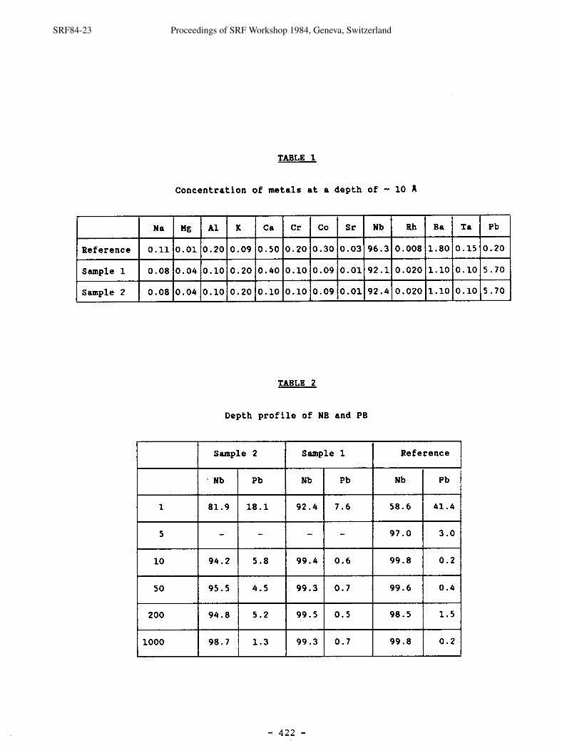
TABLE 1
Concentration o f meta l s a t a depth o f - 10 A
TABLE 2
Depth p r o f i l e o f NB and PB
Pb
0.20
5.70
5.70
1
5
10
50
200
1000
Rh
0.008
0.020
0.020
Nb
96.3
92.1
92.4
Reference
Sample 1
Sample 2
K
0.09
0.20
0.20
Ba
1.80
1.10
1.10
Sample 2
Na
0.11
0.08
0.08
Ta
0.15
0.10
0.10
Nb
81.9
-
94.2
95.5
94.8
98.7
Ca
0.50
0.40
0.10
Sample 1
Pb
18.1
-
5.8
4.5
5.2
1.3
Mg
0.01
0.04
0.04
Nb
92.4
-
99.4
99.3
99.5
99.3
Reference
Cr
0.20
0.10
0.10
A1
0.20
0.10
0.10
Pb
7.6
-
0.6
0.7
0.5
0.7
Nb
58.6
97 .O
99.8
99.6
98.5
99.8
Pb
41.4
3.0
0.2
0.4
1.5
0.2
CO
0.30
0.09
0.09
Sr
0.03
0.01
0.01
SRF84-23 Proceedings of SRF Workshop 1984, Geneva, Switzerland
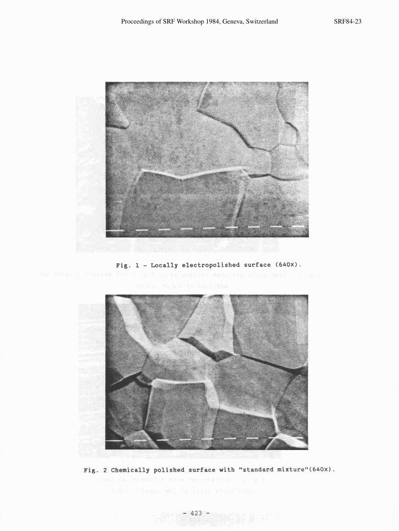
Fig. 1 - Locally electropolished surface (640x1.
Fig. 2 Chemically polished surface with "standard mixture"(640~).
- 423 -
Proceedings of SRF Workshop 1984, Geneva, Switzerland SRF84-23
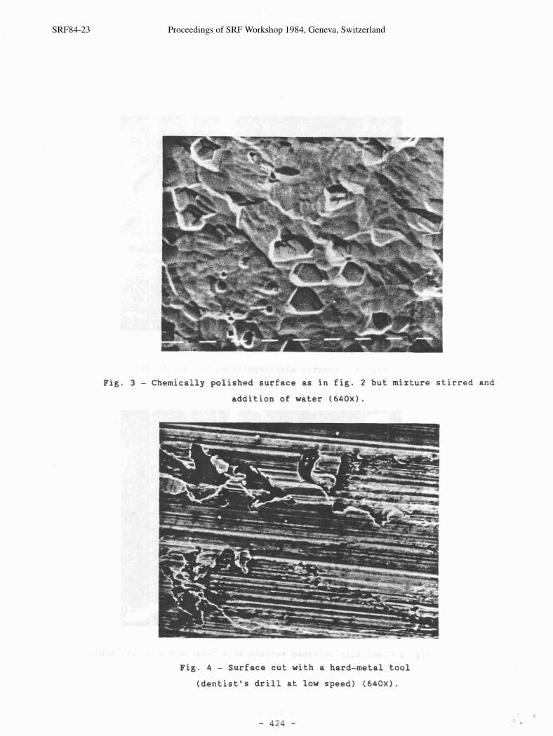
Fig. 3 - Chemically polished surface as in fig. 2 but mixture stirred and addition of water ( 640x1 .
Fig. 4 - Surface cut with a hard-metal tool
(dentist's drill at low speed) ( 6 4 0 X ) .
SRF84-23 Proceedings of SRF Workshop 1984, Geneva, Switzerland
"a- -- :- \
Fig. 5 - Surface cut with a chisel ( 2 0 x 1 .
Fig. 6 - Same as fig. 5 at the end of the groove (320x1.
- 425 -
Proceedings of SRF Workshop 1984, Geneva, Switzerland SRF84-23
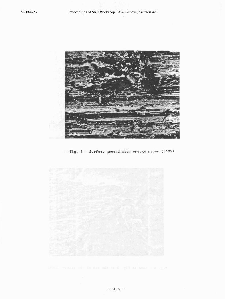
Fig. 7 - Surface ground with emergy paper ( 6 4 0 x 1 .
SRF84-23 Proceedings of SRF Workshop 1984, Geneva, Switzerland