Embed Size (px)
Citation preview
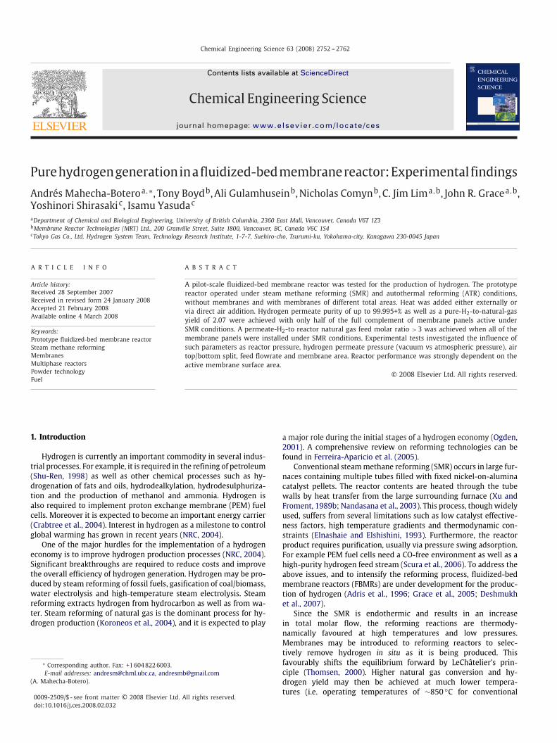
Chemical Engineering Science 63 (2008) 2752 -- 2762
Contents lists available at ScienceDirect
Chemical Engineering Science
journal homepage: www.e lsev ier .com/ locate /ces
Purehydrogengenerationinafluidized-bedmembranereactor:Experimental findings
Andrés Mahecha-Boteroa,∗, Tony Boydb,Ali Gulamhuseinb,Nicholas Comynb,C. Jim Lima,b, John R. Gracea,b,Yoshinori Shirasakic, Isamu Yasudac
aDepartment of Chemical and Biological Engineering, University of British Columbia, 2360 East Mall, Vancouver, Canada V6T 1Z3bMembrane Reactor Technologies (MRT) Ltd., 200 Granville Street, Suite 1800, Vancouver, BC, Canada V6C 1S4cTokyo Gas Co., Ltd. Hydrogen System Team, Technology Research Institute, 1-7-7, Suehiro-cho, Tsurumi-ku, Yokohama-city, Kanagawa 230-0045 Japan
A R T I C L E I N F O A B S T R A C T
Article history:Received 28 September 2007Received in revised form 24 January 2008Accepted 21 February 2008Available online 4 March 2008
Keywords:Prototype fluidized-bed membrane reactorSteam methane reformingMembranesMultiphase reactorsPowder technologyFuel
A pilot-scale fluidized-bed membrane reactor was tested for the production of hydrogen. The prototypereactor operated under steam methane reforming (SMR) and autothermal reforming (ATR) conditions,without membranes and with membranes of different total areas. Heat was added either externally orvia direct air addition. Hydrogen permeate purity of up to 99.995+% as well as a pure-H2-to-natural-gasyield of 2.07 were achieved with only half of the full complement of membrane panels active underSMR conditions. A permeate-H2-to reactor natural gas feed molar ratio >3 was achieved when all of themembrane panels were installed under SMR conditions. Experimental tests investigated the influence ofsuch parameters as reactor pressure, hydrogen permeate pressure (vacuum vs atmospheric pressure), airtop/bottom split, feed flowrate and membrane area. Reactor performance was strongly dependent on theactive membrane surface area.
© 2008 Elsevier Ltd. All rights reserved.
1. Introduction
Hydrogen is currently an important commodity in several indus-trial processes. For example, it is required in the refining of petroleum(Shu-Ren, 1998) as well as other chemical processes such as hy-drogenation of fats and oils, hydrodealkylation, hydrodesulphuriza-tion and the production of methanol and ammonia. Hydrogen isalso required to implement proton exchange membrane (PEM) fuelcells. Moreover it is expected to become an important energy carrier(Crabtree et al., 2004). Interest in hydrogen as a milestone to controlglobal warming has grown in recent years (NRC, 2004).
One of the major hurdles for the implementation of a hydrogeneconomy is to improve hydrogen production processes (NRC, 2004).Significant breakthroughs are required to reduce costs and improvethe overall efficiency of hydrogen generation. Hydrogen may be pro-duced by steam reforming of fossil fuels, gasification of coal/biomass,water electrolysis and high-temperature steam electrolysis. Steamreforming extracts hydrogen from hydrocarbon as well as from wa-ter. Steam reforming of natural gas is the dominant process for hy-drogen production (Koroneos et al., 2004), and it is expected to play
∗ Corresponding author. Fax: +16048226003.E-mail addresses: [email protected], [email protected]
(A. Mahecha-Botero).
0009-2509/$ - see front matter © 2008 Elsevier Ltd. All rights reserved.doi:10.1016/j.ces.2008.02.032
a major role during the initial stages of a hydrogen economy (Ogden,2001). A comprehensive review on reforming technologies can befound in Ferreira-Aparicio et al. (2005).
Conventional steammethane reforming (SMR) occurs in large fur-naces containing multiple tubes filled with fixed nickel-on-aluminacatalyst pellets. The reactor contents are heated through the tubewalls by heat transfer from the large surrounding furnace (Xu andFroment, 1989b; Nandasana et al., 2003). This process, thoughwidelyused, suffers from several limitations such as low catalyst effective-ness factors, high temperature gradients and thermodynamic con-straints (Elnashaie and Elshishini, 1993). Furthermore, the reactorproduct requires purification, usually via pressure swing adsorption.For example PEM fuel cells need a CO-free environment as well as ahigh-purity hydrogen feed stream (Scura et al., 2006). To address theabove issues, and to intensify the reforming process, fluidized-bedmembrane reactors (FBMRs) are under development for the produc-tion of hydrogen (Adris et al., 1996; Grace et al., 2005; Deshmukhet al., 2007).
Since the SMR is endothermic and results in an increasein total molar flow, the reforming reactions are thermody-namically favoured at high temperatures and low pressures.Membranes may be introduced to reforming reactors to selec-tively remove hydrogen in situ as it is being produced. Thisfavourably shifts the equilibrium forward by LeChâtelier's prin-ciple (Thomsen, 2000). Higher natural gas conversion and hy-drogen yield may then be achieved at much lower tempera-tures (i.e. operating temperatures of ∼850 ◦C for conventional

A. Mahecha-Botero et al. / Chemical Engineering Science 63 (2008) 2752 -- 2762 2753
reforming vs ∼550 ◦C for membrane reformers) if the product hy-drogen is removed from the reactor (Raich and Foley, 1995; Mleczkoet al., 1996; Adris et al., 1997). In addition, the catalyst effectivenessfactor increases by several orders of magnitude when a fine fluidizedcatalyst powder is implemented instead of catalyst pellets. Moreover,fluidized-bed operations are characterized by very low temperaturegradients due to the intensive mixing of particles inside the reactor(Yates, 1983; Kunii and Levenspiel, 1991; Deshmukh et al., 2005).Other advantages of FBMR include the possibility of using inexpen-sive metal alloys (i.e. due to its lower operating temperatures) aswell as continuous/periodic catalyst replacement (Grace et al., 2005).However, FBMRs present challenges such as the possibility of cata-lyst attrition/erosion, a more complex design/scale-up/constructionprocess as well as the need for reliable membranes.
Given these advantages of FBMRs, a number of theoretical andexperimental studies have been performed in recent years. For exam-ple, there has been considerable modelling effort (Adris et al., 1997;Grace et al., 2001; Abba et al., 2003; Chen et al., 2003a--c, 2004,2008; Dogan et al., 2003; Prasad and Elnashaie, 2004; Patil et al.,2005). Experimental studies and reactor developments have beencarried out by several groups. A pilot reactor of 97mm ID, with theprovision of palladium tubes was implemented by Adris et al. (1994).Roy (1998) used high-flux membranes and heating via oxygen ad-dition in a FBMR. A high-temperature downflow-fluidized bed withthe provision of inconel supported palladium membranes was oper-ated by Jarosch and de Lasa (1999). Similarly, a 0.1m ID, 2.7m tallfluidized-bed reactor with both Pd-based H2 perm-selective mem-branes and perovskite O2 perm-selective membranes for autother-mal reforming (ATR) was operated under SMR conditions by Patilet al. (2006). Boyd (2007) successfully operated a 0.13m ID, 2.3mtall internally circulating FBMR. More recently a 0.13m ID, 1.6m tallmembrane reactor was operated by Chen et al. (2007) under ATRand SMR conditions. The FBMR process is currently being commer-cialized by Membrane Reactor Technologies (MRT) Limited (Adriset al., 1994; Grace et al., 2006; Deshmukh et al., 2007).
This paper presents new experimental results showing the in-fluence of such parameters as reactor pressure, hydrogen perme-ate pressure (vacuum vs atmospheric pressure), air top/bottom split,feed flowrate and membrane area in a novel pilot FBMR.
2. Experimental studies
2.1. Operation modes
A FBMR may be operated under different operating modes de-pending on how the heat required for the reforming reactions issupplied:
2.1.1. SMR with external heatingUnder these conditions, the endothermic reactor heat is provided
by indirect heat transfer from hot furnace gases, but for the pilotreactor, electrical heaters were used. This mode is attractive due itshigh hydrogen recovery, although it is subject to heat transfer con-straints. The main reactions under SMR operation (Xu and Froment,1989a, b) are:
Methane steam reforming (R1):
CH4 + H2O ↔ CO + 3H2 (�H0298 = 206.2kJmol−1).
Water--gas shift (R2):
CO + H2O ↔ CO2 + H2 (�H0298 = −41.2kJmol−1).
Methane overall steam reforming (R3):
CH4 + 2H2O ↔ CO2 + 4H2 (�H0298 = 165kJmol−1),
where R3 is the sum of R1 and R2.
2.1.2. ATR with addition of air or oxygenIn oxidative steam reforming, oxygen is supplied to the reactor
to oxidize combustibles, thereby generating the required heat (Royet al., 1999; Hoang and Chan, 2004; Prasad, 2004). When the heatgenerated by the oxidation/combustion reactions balances the heatintake of the reforming reactions and heat losses, the system oper-ates autothermally. Since heat is generated inside the fluidized beditself, heat transfer limitations are not an issue during ATR opera-tion. Reforming reactions R1--R3, as well as methane combustion R4(Jin et al., 2000) and hydrogen combustion R5 (Låte et al., 2004a, b),occur simultaneously during ATR of methane. Oxygen introductionlocally increases methane conversion, increases reactor temperatureand reduces hydrogen yield.
Methane combustion (R4):
CH4 + 2O2 ↔ CO2 + 2H2O (�H0298 = −802.7kJmol−1).
Hydrogen combustion (R5):
H2 + 12O2 ↔ H2O (�H0
298 = −242kJmol−1).
2.2. Experimental equipment
Fig. 1 provides a schematic drawing of the overall experimen-tal setup tested in this work. Natural gas from the city lines wascompressed and then desulphurized. Sulphur components were ef-fectively removed to prevent catalyst deactivation. We used a bedof Cu-impregnated activated carbon for sulphur removal (CalgonSulfasorb-8) so that sulphur levels were small. The city natural gaslines contain about 13mg Sm−3. Our measurements of the desul-phurized natural gas stream indicate its sulphur content was kept al-ways below 0.28mgSm−3. The desulphurized natural gas was thencombined with previously deionized and compressed water. The re-sulting stream was then introduced into a vaporizer which raisedthe fluid temperature to ∼ 550 ◦C. The pre-heated water/natural gasstream was next fed to a gas distributor at the base of the FBMR. Airfrom gas cylinders was divided into two streams (i.e. via distributorsat the bottom of the bed as well as at 0.024m below the freeboard).In the case of ATR operation the reactor was fed with air near boththe top and bottom of the bed. The heat generated by the oxida-tive reactions was distributed throughout the bed by the particlesdepending on the top/bottom air split. Pure hydrogen product wasremoved via hydrogen selective membranes connected to a vacuumpump, which withdraws hydrogen at a pressure of 30kPa(a), thusincreasing the hydrogen permeation driving force. The remaining re-actor gas products leave the system after passing through sinteredmetal filters at the top of the fluidized-bed freeboard to remove en-trained particulates.
The test rig allowed several process variables to be controlledaccurately. The main controllable parameters for each experimentalrun are listed in Table 1.
2.3. Pilot FBMR
The pilot reactor has a nominal capacity of 1.0Nm3 h−1 of perme-ate H2 under ATR conditions, with a pressure rating of 1000kPa(g).The reactor is contained in a stainless steel vessel of height 2m andrectangular cross-sectional area of 48.4 cm2. The vessel can hold upto six double-sided membrane modules with a nominal permeationarea of 300 cm2 (provided by MRT Limited). The membrane modulescontained Pd/Ag foil of thickness 25�m sealed onto a porous metalbacking with a barrier layer to prevent interdiffusion. No sweep gaswas used in any of the runs discussed here. SMR catalyst particlesof average particle diameter 90�m were introduced to the reactor.These catalyst particles have a measured minimum superficial gasvelocity for fluidization of 0.0030ms−1 in atmospheric air. Catalyst

2754 A. Mahecha-Botero et al. / Chemical Engineering Science 63 (2008) 2752 -- 2762
Fig. 1. Experimental setup schematic drawing. ROG, reactor off-gas.
Table 1Controlled parameters for experimental program
Controlled variables Equipment/action
Flowrate of natural gas Flow controller actionFlowrate of water Modulation of water pumpFlowrate of air (ATR operation) Flow controller actionNatural gas/water input mixturepre-heat temperature
Modulation of pre-heater output
Split of air flow between top andbottom nozzles (ATR operation)
Flow controller action
Pressure on permeate side Modulation of vacuum pump speedReactor pressure Adjustment of off-gas exit valveReactor temperature Flow controller action on top/bottom air
Adjusting internal heaters outputAdjusting external heaters output
minimum fluidization velocity under reforming conditions was pre-dicted to be 0.0018ms−1. The fluidized bed operated at all timeswithin the bubbling fluidization regime.
The non-permeate reactor off-gas (ROG) leaving the top of the re-actor was analysed at the exit. In addition, reactor gas was sampledat the middle of each membrane section. These gas lines were con-nected to a gas chromatograph for chemical composition analysis.Reactor temperature was measured continuously at six points alongthe reactor. During SMR operation internal electrical heaters at thefour corners controlled the reactor temperature. The split of flow tothe top/bottom air distributors was controlled during ATR operation.External electric heaters were also utilized for reactor start-up andto compensate for heat losses.
After completing the start-up process, measurements were madeto characterize the reactor performance for different operating con-ditions. The main measured steady-state operating variables for eachexperimental run are:
• Temperature profile. Six points: one on each membrane panel, oneembedded in the bottom distributor, one in the freeboard and onein the top air distributor.
• In-bed and ROG reactor gas samples concentration from chromato-graph (H2, N2, CO, CH4, CO2).
• Flowrate of pure hydrogen from membranes.• Hydrogen purity from gas chromatograph.• Feed pressure. Pressure just above distributor. Differential pressure
between distributor and freeboard. Pressure drop across the filters.
2.4. Membranes for hydrogen removal
Perm-selective membranes are intended to break the thermody-namic barrier and shift the equilibrium forward to enhance hydro-gen production while also purifying the product. Ceramic, metallicand composite membranes have all been proposed for hydrogen pu-rification (Uemiya, 2004). Palladium alloy membranes are used mostwidely for selective hydrogen removal, having a nearly infinite se-lectivity since, only atomic hydrogen can diffuse through the metalfoil (Shu et al., 1994, 1996). The accepted mechanism for hydrogenpermeation through dense metallic membranes (Paglieri and Way,2002) is:
(1) transport of H2 molecules to the surface of the metallic mem-brane;
(2) reversible chemisorption of H2 molecules on the metal surface;(3) reversible dissolution of atomic hydrogen at the membrane sur-
face;(4) diffusion of atomic hydrogen through the metal lattice (usually
the rate-controlling step);(5) reassociation of atomic hydrogen at the surface of the down-
stream metal surface;(6) desorption of molecular hydrogen from the metal surface; and(7) H2 transport away from the outer surface of the membrane.
The geometric configuration of the membranes inside the reactoris depicted in Fig. 2. The membrane permeate side has a thicknessof 6.4mm. Permeate hydrogen is withdrawn from each panel via a1/4 in (6.4mm) stainless steel tube. A schematic representation of amembrane panel is depicted in Fig. 2.

A. Mahecha-Botero et al. / Chemical Engineering Science 63 (2008) 2752 -- 2762 2755
Fig. 2. Reactor configuration, and palladium membrane details.
The flow of hydrogen permeating through a membrane surfacecan be estimated by Sieverts' Law (Sieverts and Zapf, 1935a, b):
FH2(�)= AM · JH2(�)
= AM ·[
kH2�H2
· e(−EH2/R.T(�)) ·
(√PH2(�)
−√
PH2(M)
)], (1)
where FH2(�)is the total molar flow rate of hydrogen extracted
through perm-selective membranes, AM is the effective membranesurface area, JH2(�)
is the membrane flux, �H2is the foil thickness,
T(�) is the membrane surface temperature, PH2(�)is the partial
pressure of hydrogen in the reactor, PH2(M)is the partial pressure of
hydrogen in the permeate side. Other symbols are defined in thenotation section.
2.5. Catalyst
A nickel oxide catalyst supported on alumina was utilized for allSMR experiments. A precious metal catalyst also supported on alu-mina was utilized for the ATR pilot tests. The reforming reactionswere quite fast, and catalyst deactivation was not expected to bean issue over the limited time of operation and given the steam-to-carbon molar ratio of 3.0 for all experimental runs. The reactor op-erated at low superficial gas velocities (bubbling fluidization regimewith superficial gas velocities �0.08ms−1) resulting in very lowcatalyst attrition rates and negligible wastage of the membrane sur-faces.
2.6. Experimental design
Several experimental runs were conducted under SMR and ATRconditions, with a total operational time of 178h. The performance ofall reactor components and systems was tested and the functionalityof safety systems was verified. Steam reforming experiments underSMR and ATR conditions, both with and without membranes werecarried out with different numbers of active membranes. Reactorcommissioning was performed without membranes (with metallicdummies replacing the membrane panels), and then reforming ex-periments were conducted with either half (three membranes, threedummies) or all six membrane panels installed. All dummies wereof identical area and thickness as the membrane panels.
The experimental variables are summarized in Table 2. Operatingconditions can be used for a sensitivity analysis as per Table 3.
2.7. Gas sampling
Gas sampling lines were connected to the fluidized-bed reactorto obtain axial concentration profiles of H2, N2, CO, CH4 and CO2along the bed. A fine metallic mesh acted as a filter on each samplingport to exclude catalyst powder from entering the sampling tubes.Each sampling line was coiled and quenched by being submerged ina cold water bath. Sample gas was throttled with manual valves toa flowrate appropriate for the gas chromatograph sampling system.This, combined with long sampling tubes from the reactor to the GC,caused delays in the sampling process. To address the delay issue,the following steps were followed:
• The gas residence times in the sampling lines were determined,and samples were required to exceed these times.

2756 A. Mahecha-Botero et al. / Chemical Engineering Science 63 (2008) 2752 -- 2762
Table 2Experimental conditions
Expt. # Membranes installed O2/CH4 ratio Air split (% to top) Natural gas feed (Nm3 h) Reactor pressure (kPa(g)) Permeate pressure (kPa(a))
1 0 0 N/A 0.896 650 N/A2 0 0 N/A 0.896 900 N/A3 0 0.35 14.7 0.896 900 N/A4 3 0 N/A 0.896 650 1015 3 0 N/A 0.896 650 306 3 0 N/A 0.896 900 307 3 0 N/A 0.448 650 308 3 0 N/A 0.448 900 309 6 0.35 50 0.896 900 10110 6 0.35 50 0.896 900 3011 6 0.35 25 0.896 900 3012 6 0.35 10.4 0.448 900 3013 6 0.35 6.2 0.298 900 3014 6 0 N/A 0.298 900 30
N/A: not applicable.
All experiments were carried out at 550 ◦C with a steam-to-carbon molarratio of 3.0.
Table 3Justification of selected operating conditions
Experiments Analysis
(1) vs (2) Effect of reactor pressure without hydrogen removal(5) vs (6) and (7) vs (8) Effect of reactor pressure with hydrogen removal(1) vs (4) and (2) vs (6) Effect of area of membranes in SMR(3) vs (9), (3) vs (10) and(3) vs (11)
Effect of area of membranes in ATRa
(4) vs (5) Effect of permeate pressure in SMR(9) vs (10) Effect of permeate pressure in ATR(2) vs (3), (6) vs (10)and (8) vs (12)
Effect of oxygen input (SMR vs ATR)
(10) vs (11) Effect of air split in ATR(5) vs (7) and (6) vs(8) vs (14)
Effect of reducing feed rates in SMR
(11) vs (12) vs (13) Effect of reducing feed rates in ATRa
aNot exactly comparable due to variation in air split.
• Each sample was analysed repeatedly until steady state wasachieved. Typically, gas samples were analysed until <1% varia-tion on methane conversion was indicated.
• Only samples which satisfy the above two conditions are includedin the results.
• Each sample was repeated at least three times to ensure repro-ducibility of the results.
For each value measured, a simple error-bar (represented by thestandard error) was calculated by dividing the standard deviation bythe square root of number of experimental measurements that makeup the mean. In some plots, the error-bars are very small and do notappear on the figures. In some cases when the values of a measuredstate variable are small, the error-bars appear large due to the scaleof the figures.
3. Results and discussion
3.1. Overall reactor performance
Table 4 provides the typical composition of the naturalgas from the city lines. The natural gas feed to the reactor ismainly composed by methane, which is used as model compo-nent for the subsequent calculations. Table 5 summarizes theperformance of the reacting system. Table 6 contains a typ-ical gas chromatograph analyses for one of the reactor gassamples under SMR and ATR conditions. The natural gas con-version at the different sampling points was calculated from
Table 4Typical feed natural gas analysis
Component Mole fraction
Methane 0.955Ethane 0.029Nitrogen 0.007Propane 0.005Carbon dioxide 0.002n-Butane 0.001iso-Butane 0.0005Pentanes 0.0004Hexanes 0.0001
an overall carbon balance, as indicated by
XCH4(�)=⎛⎝ YCO2(�)
+ YCO(�)
YCO2(�)+ YCO(�)
+ YCH4(�)
⎞⎠ , (2)
where XCH4(�)is the reactor conversion of methane and YCO2(�)
,
YCO(�)and YCH4(�)
are the reactor gas mole fractions of carbon diox-
ide, carbon monoxide and methane, respectively.Measured ROG methane conversions in the freeboard tended to
be low due to reverse reaction (see reactions R1--R3) because of adrop in temperature (∼ 100 to ∼ 250 ◦C cooler than the main reac-tor). Samples taken directly from the reactor showmuch higher con-versions, as the gas samples were rapidly quenched out of contactwith the catalyst. In-bed gas samples were not taken during someexperiments (designated by an asterisk in Table 5); only ROG mea-surements were performed for these cases, providing low methaneconversion values. In practice the freeboard could be heated if thisis important to obtain a reformate from the ROG, as discussed belowin Section 3.2.2.
Hydrogen purity was high, ∼ 99.99%, during all experimentalruns. Some trace impurities on the permeate side could be causedby residues in the gas chromatograph lines, but minor imperfectionsin the palladium foil are thought to be the main source of non-hydrogen gases (mainly CH4 and some CO2). Methane traces mayhave appeared if some methanation occurred in the sampling lines(Jorgensen et al., 1995).
Methanation (R6):
C(S) + 2H2 ↔ CH4 (�H0298 = −74.82kJmol−1).
CO was not detected during any of the experimental runs, an impor-tant finding with respect to PEM fuel cells applications.

A. Mahecha-Botero et al. / Chemical Engineering Science 63 (2008) 2752 -- 2762 2757
Table 5Experimental results
Expt. # Maximum natural gasconversion (%)
Maximum H2 ROG molefraction (dry) (%)
Permeate H2 flow(Nm3 h−1)
Maximum perm.H2/C molar ratio
Detected permeate H2purity (%)
1 28.9 43.5 N/A N/A N/A2 21.5 33.3 N/A N/A N/A3 40.0 22.2 N/A N/A N/A4a ROG: 25 40.1 0.31 0.38 99.9675 65.5 41.1 0.88 0.98 99.9956 65.8 33.3 0.94 1.05 99.9887a ROG: 43.0 29.4 0.93 2.07 99.9888 66.5 20.6 0.92 2.06 99.9409a ROG: 45.9 22.0 Not available Not available Not available10 73.1 17.5 1.11 1.28 99.96711 68.7 16.2 1.08 1.23 99.99512 80.9 11.9 0.82 1.93 99.98813a ROG: 75.8 8.69 0.73 2.53 99.98814 73.1 8.72 0.89 3.03 99.940
N/A: not applicable.aIn-bed gas sampling not performed.
Table 6Typical reactor gas composition (dry basis)
Case H2 (%) N2 (%) CO (%) CH4 (%) CO2 (%)
Expt. #5 (SMR) 37.4 6.54 3.63 19.3 33.1Expt. #12 (ATR) 12.1 52.1 2.06 6.83 26.9
Samples taken at central membrane level.
Fig. 3. Temperature vs height for experiments 4--8. Membrane isothermality. Forexperimental conditions, see Table 2.
3.2. Influence of key operating parameters
The continuous lines in Figs. 3--7 and Figs. 9--14 are trendlinesthrough the experimental points of temperature, concentration, con-version and permeate yield. For experimental conditions see Table 2.
3.2.1. Membrane isothermalityThe membrane panels are exposed to a nearly isothermal envi-
ronment. Temperature variation along each membrane panel wasless than 20 ◦C. This helps to preserve membrane longevity. Theability of moving solids to circulate heat and minimize tempera-ture gradients is a major advantage of fluidized beds compared toconventional fixed-beds. Fig. 3 depicts typical temperature profilesfor the FBMR during SMR operation. It is clear that for all exper-imental runs the membrane-containing sections retained uniform
temperatures, although, as noted above, there was significant cool-ing in the freeboard.
3.2.2. Heat effectsAn axial profile of natural gas conversion is plotted in Fig. 4 with
its corresponding bed temperature profile. This figure shows typicalbehaviour of the FBMR unit under ATR conditions. Air was injectedat both the top and bottom of the dense-phase portion of the re-actor to provide heat for the endothermic reforming reactions. Theoxidation reactions increased methane conversion and reactor tem-perature near the injection points. During ATR operation the systemno longer relied on electrical heaters to provide the endothermic re-action heat. The bed temperature increased near the top air distrib-utor. Nevertheless, there were no reactor hot-spots, a feature of awell-mixed fluidized bed due to the circulation of heat by the solidparticles.
The temperature drop in the reactor freeboard was common toall experimental runs, leading to a decrease in reactant conversiondue to reverse reactions (Adris and Grace, 1997). Note that thesefreeboard effects are not a problem for the intended application sincethey occurred beyond the upper level where product hydrogen wasextracted. In addition, the exothermic reverse reactions may givesome heat back to the reactor. Nevertheless, three methods maybe combined to address this issue if the non-permeate reformateproduct is important:
(a) Heating the freeboard: External heating could be provided toavoid cooling.
(b) Rapid quenching of ROG line: Currently the ROG line is well in-sulated. If the insulation were to be removed, the output gaswould cool very quickly, as for the gas samples extracted fromthe side flanges.
(c) Improve ROG filters/cyclones: This may prevent small catalystfines from entering the ROG line.
3.2.3. Thermodynamic effect of reactor pressureSMR is thermodynamically enhanced by low reactor pressures.
Higher equilibrium conversions are experienced at low pressuresfor reformers without membranes due to the increase in total molarflowrate. During reactor commissioning, the experimental setup wasoperated using metallic dummy panels instead of palladium mem-branes. Axial conversion profiles at different reactor pressures areplotted in Fig. 5. As expected the system achieved a higher methaneconversion at the lower pressure. When operating with active

2758 A. Mahecha-Botero et al. / Chemical Engineering Science 63 (2008) 2752 -- 2762
Fig. 4. Natural gas conversion and temperature vs height for typical ATR operation (Experiment 10). For experimental conditions, see Table 2.
Fig. 5. Natural gas conversion vs height for Experiments 1 (650kPa) and 2 (900kPa).Thermodynamic effect of reactor pressure. For experimental conditions, see Table 2.
membranes, this thermodynamic effect is offset to a significantextend by an increase in hydrogen removal, significantly offsettingthe negative shift in the thermodynamic equilibrium.
3.2.4. Effect of membrane areaThe FBMR is rate-controlled by membrane permeation. For
the temperatures and catalyst loadings of interest, the steamreforming kinetics are fast enough that our kinetic model predictsnear-equilibrium gas compositions. If hydrogen permeation could beincreased, the equilibrium conversion would be further enhanced.For currently available hydrogen producing membrane reactors, theinstalled membrane surface area dominates reactor performance(Adris and Grace, 1997; Boyd et al., 2005). It is therefore importantto maximize the membrane area per unit reactor volume as well asto minimize the membrane thickness. The first aspect depends onthe reactor configuration and height, whereas the thickness requiresa balance between hydrogen flux, selectivity and longevity.
The membrane permeation may be increased by increasingthe pressure driving force across the membrane as described by
Fig. 6. Natural gas conversion vs height for Experiments 6 (three membranes) and 2(no membranes). Effect of membrane area during SMR operation. For experimentalconditions, see Table 2.
Sieverts' Law (see Eq. (1)). Hydrogen extraction can also be increasedby installing more membrane surface area in the reactor. Fig. 6presents the effect of increasing membrane area on methane con-version during SMR operation. Fig. 7 displays the effect of increasingmembrane area on methane conversion and reactor hydrogen com-position during ATR operation. It is clear that a higher hydrocarbonconversion was achieved by increasing the membrane area. Fur-thermore, it is observed that there was a significant decrease in theconcentration of hydrogen in the reactor due to the presence ofmembranes. For the cases with active membranes, the content ofhydrogen in the reactor increased sharply in the lower section of thebed due to the rapid kinetics. This concentration decreased gradu-ally during the middle section of the bed due to hydrogen removalas seen in Fig. 7. In the upper part of the bed, there was an increasein hydrogen content due to reverse reactions as described above.
3.2.5. Effect of pressure driving forceHydrogen removal increases monotonically with an increase
in pressure differential between the reactor and permeate. The

A. Mahecha-Botero et al. / Chemical Engineering Science 63 (2008) 2752 -- 2762 2759
Fig. 7. Natural gas conversion and dry H2 molar fraction vs height for Experiments 11 (six membranes) and 3 (no membranes). Effect of membrane area during ATRoperation. For experimental conditions, see Table 2.
Fig. 8. Hydrogen production vs reactor pressure and permeate pressure. (Experi-ments 4--6). Effect of pressure driving force on hydrogen removal. For experimentalconditions, see Table 2.
thermodynamic advantage of operating at low reactor pressures(see Section 3.2.3) is largely neutralized with the introduction ofhydrogen removal membranes. Fig. 8 depicts the effect of pressuredifferential on hydrogen production (see Eq. (1)). Since the drivingforce is dependent on the difference between the square roots ofthe hydrogen partial pressures, we can observe a more significantvariation in driving force by adjusting the pressure in the perme-ate side (containing pure hydrogen so that: PH2(M)
= P(M)) than by
varying the reactor pressure (i.e. where hydrogen partial pressureaccounts for only a fraction of the total pressure as per Dalton's law
Fig. 9. Effect of reactor pressure on natural gas conversion vs height. For experimentalconditions, see Table 2, for Experiments 5 and 6.
of partial pressures: PH2(�)= YH2(�)
.P(�)). Fig. 9 portraits a small
increase in conversion due to the increase in reactor pressure forExperiments 5 and 6.
3.2.6. Effect of air input (SMR vs ATR)Fig. 10 shows the overall effect of air input. A fraction of the oxi-
dizing air is fed at the bottom distributor converting methane almostinstantaneously and therefore generating heat for the endothermicreforming reactions. A higher natural gas conversion is observed inthe ATR cases compared to corresponding SMR cases. As discussedabove, there is an increase in temperature as well as higher methaneconversion in the top distributor region due to the exothermic com-bustion of methane and hydrogen, as depicted in Figs. 4 and 10.Reverse reactions are a little less significant during autothermal oper-ation than during SMR. In addition, ATR runs required∼37% less elec-trical heating power than their SMR counterparts, a significant re-

2760 A. Mahecha-Botero et al. / Chemical Engineering Science 63 (2008) 2752 -- 2762
Fig. 10. Natural gas conversion and temperature vs reactor height for Experiments 2 (SMR) and 3 (ATR). Effect of oxygen input. For experimental conditions, see Table 2.
Fig. 11. Effect of air distribution on natural gas conversion vs height. For experimentalconditions, see Table 2, Experiments 10 and 11.
duction in a small-scale prototype characterized by high heat lossesdue to its high shell surface area per unit volume.
3.2.7. Effect of air splitAir or pure oxygen may be injected during ATR operations. Air is
generally preferred for economic reasons since it does not requireoxygen separation. However, nitrogen feed to the reactor in the ox-idant air reduces H2 recovery by diluting the reactor gases, thuslowering the H2 diving force across the membranes. This nitrogenpenalty may be diminished by introducing as much air as possibleat the top of the reactor, relying on catalyst internal circulation tocarry heat back to the bottom. The higher the proportion of air fedto the top of the reactor, the lower the nitrogen penalty, but at theexpense of a larger axial temperature gradient.
Experiments 10 and 11 were conducted under almost identicaloperating conditions, the only difference being their top/bottom airsplit. Fig. 11 plots the axial conversion profiles for these two exper-iments. As expected, Experiment 10 showed a better performance.This demonstrates that more air feed to the top of the reactor im-proves hydrogen yield because of a diminished nitrogen penalty.
Fig. 12. Nitrogen concentration vs height for experiments 10 (50% air at top), 11 (25%air at top) and 12 (10.4% air at top). Gas backmixing. For experimental conditions,see Table 2.
3.2.8. Gas backmixingDownflow of particles in fluidized beds causes axial dispersion
and backmixing of gas. By tracking the concentration of nitrogenalong the reactor height it is possible to establish as in Fig. 12, howfar the oxidizing stream backmixes along the reactor. This effectis important with respect to the nitrogen penalty when air is fedat the top of the reactor. Some short range gas backmixing wasencountered in these tests. Since the total volumetric flowrate of gasvaries along the reactor due to chemical reaction, species removal aswell as temperature and pressure gradients, it is difficult to establishthe dispersion of nitrogen quantitatively. Nevertheless, if changes involumetric flowrate are ignored, the amount of N2 backmixed fromthe top nozzle to the uppermembrane level can be roughly estimatedto be ∼ 13% for Experiment 10, while the corresponding fractionwas ∼ 43% and ∼ 41% for Experiments 11 and 12, respectively. Thefraction of N2 that migrated as far as the middle membrane leveland below was negligible in all cases. This is a favourable resultas it indicates that any nitrogen entering with air at the top does
A. Mahecha-Botero et al. / Chemical Engineering Science 63 (2008) 2752 -- 2762 2761
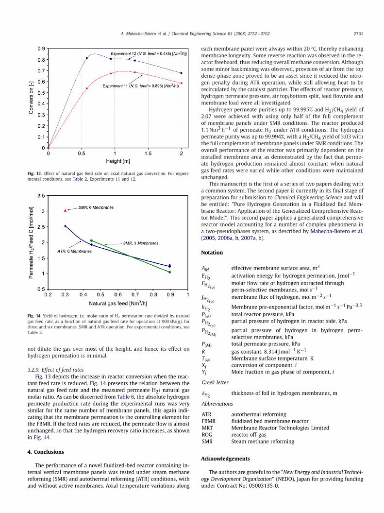
Fig. 13. Effect of natural gas feed rate on axial natural gas conversion. For experi-mental conditions, see Table 2, Experiments 11 and 12.
Fig. 14. Yield of hydrogen, i.e. molar ratio of H2 permeation rate divided by naturalgas feed rate, as a function of natural gas feed rate for operation at 900kPa(g), forthree and six membranes, SMR and ATR operation. For experimental conditions, seeTable 2.
not dilute the gas over most of the height, and hence its effect onhydrogen permeation is minimal.
3.2.9. Effect of feed ratesFig. 13 depicts the increase in reactor conversion when the reac-
tant feed rate is reduced. Fig. 14 presents the relation between thenatural gas feed rate and the measured permeate H2/ natural gasmolar ratio. As can be discerned from Table 6, the absolute hydrogenpermeate production rate during the experimental runs was verysimilar for the same number of membrane panels, this again indi-cating that the membrane permeation is the controlling element forthe FBMR. If the feed rates are reduced, the permeate flow is almostunchanged, so that the hydrogen recovery ratio increases, as shownin Fig. 14.
4. Conclusions
The performance of a novel fluidized-bed reactor containing in-ternal vertical membrane panels was tested under steam methanereforming (SMR) and autothermal reforming (ATR) conditions, withand without active membranes. Axial temperature variations along
each membrane panel were always within 20 ◦C, thereby enhancingmembrane longevity. Some reverse reaction was observed in the re-actor freeboard, thus reducing overall methane conversion. Althoughsome minor backmixing was observed, provision of air from the topdense-phase zone proved to be an asset since it reduced the nitro-gen penalty during ATR operation, while still allowing heat to berecirculated by the catalyst particles. The effects of reactor pressure,hydrogen permeate pressure, air top/bottom split, feed flowrate andmembrane load were all investigated.
Hydrogen permeate purities up to 99.995% and H2/CH4 yield of2.07 were achieved with using only half of the full complementof membrane panels under SMR conditions. The reactor produced1.1Nm3 h−1 of permeate H2 under ATR conditions. The hydrogenpermeate purity was up to 99.994%, with a H2/CH4 yield of 3.03 withthe full complement of membrane panels under SMR conditions. Theoverall performance of the reactor was primarily dependent on theinstalled membrane area, as demonstrated by the fact that perme-ate hydrogen production remained almost constant when naturalgas feed rates were varied while other conditions were maintainedunchanged.
This manuscript is the first of a series of two papers dealing witha common system. The second paper is currently in its final stage ofpreparation for submission to Chemical Engineering Science and willbe entitled: "Pure Hydrogen Generation in a Fluidized Bed Mem-brane Reactor: Application of the Generalized Comprehensive Reac-tor Model''. This second paper applies a generalized comprehensivereactor model accounting for a number of complex phenomena ina two-pseudophases system, as described by Mahecha-Botero et al.(2005, 2006a, b, 2007a, b).
Notation
AM effective membrane surface area, m2
EH2activation energy for hydrogen permeation, Jmol−1
FH2(�)molar flow rate of hydrogen extracted throughperm-selective membranes, mol s−1
JH2(�)membrane flux of hydrogen, molm−2 s−1
kH2Membrane pre-exponential factor, molm−1 s−1 Pa−0.5
P(�) total reactor pressure, kPaPH2(�)
partial pressure of hydrogen in reactor side, kPa
PH2(M)partial pressure of hydrogen in hydrogen perm-selective membranes, kPa
P(M) total permeate pressure, kPaR gas constant, 8.314 Jmol−1 K−1
T(�) Membrane surface temperature, KXi conversion of component, iYi Mole fraction in gas phase of component, i
Greek letter
�H2thickness of foil in hydrogen membranes, m
Abbreviations
ATR autothermal reformingFBMR fluidized bed membrane reactorMRT Membrane Reactor Technologies LimitedROG reactor off-gasSMR Steam methane reforming
Acknowledgements
The authors are grateful to the "New Energy and Industrial Technol-ogy Development Organization'' (NEDO), Japan for providing fundingunder Contract No: 05003135-0.

2762 A. Mahecha-Botero et al. / Chemical Engineering Science 63 (2008) 2752 -- 2762
References
Abba, I.A., Grace, J.R., Bi, H.T., 2003. Application of the generic fluidized-bed reactormodel to the fluidized-bed membrane reactor process for steam methanereforming with oxygen input. Industrial and Engineering Chemistry Research42, 2736--2745.
Adris, A.M., Grace, J.R., 1997. Characteristics of fluidized-bed membrane reactors:scale-up and practical issues. Industrial and Engineering Chemistry Research 36,4549--4556.
Adris, A.M., Grace, J.R., Lim, C.J., Elnashaie, S.S.E.H., 1994. Fluidized bed reactionsystem for steam/hydrocarbon gas reforming to produce hydrogen. USA PatentNumber 5326550.
Adris, A.M., Pruden, B.B., Lim, C.J., Grace, J.R., 1996. On the reported attempts toradically improve the performance of the steam methane reforming reactor. TheCanadian Journal of Chemical Engineering 74, 177--186.
Adris, A.M., Lim, C.J., Grace, J.R., 1997. The fluidized bed membrane reactor forsteam methane reforming: model verification and parametric study. ChemicalEngineering Science 52, 1609--1622.
Boyd, T., 2007. Hydrogen from an internally circulating fluidized bed membranereactor. Ph.D. Thesis, University of British Columbia, Vancouver.
Boyd, T., Grace, J.R., Lim, C.J., Adris, A., 2005. Hydrogen from an internally circulatingfluidized bed membrane reactor. International Journal of Chemical ReactorEngineering 3, A58.
Chen, Z., Prasad, P., Yan, Y., Elnashaie, S.S.E.H., 2003a. Simulation for steam-reformingof natural gas with oxygen input in a novel membrane reformer. Fuel ProcessingTechnology 83, 235--252.
Chen, Z., Yan, Y., Elnashaie, S.S.E.H., 2003b. Modeling and optimization of a novelmembrane reformer for higher hydrocarbons. A.I.Ch.E. Journal 49, 1250--1265.
Chen, Z., Yan, Y., Elnashaie, S.S.E.H., 2003c. Novel circulating fast fluidized-bedmembrane reformer for efficient production of hydrogen from steam-reformingof methane. Chemical Engineering Science 58, 4335--4349.
Chen, Z., Yan, Y., Elnashaie, S.S.E.H., 2004. Catalyst deactivation and engineeringcontrol for steam-reforming of higher hydrocarbons in a novel membranereformer. Chemical Engineering Science 59, 1965--1978.
Chen, Z., Grace, J.R., Lim, C.J., Li, A., 2007. Experimental studies of pure hydrogenproduction in a commercialized fluidized-bed membrane reactor with SMR andATR catalysts. International Journal of Hydrogen Energy 32 (13), 2359--2366.
Chen, Z., Po, F., Grace, J.R., Jim Lim, C., Elnashaie, S., Mahecha-Botero, A., Rakib,M., Shirasaki, Y., Yasuda, I., 2008. Sorbent enhanced/membrane-assisted steammethane reforming. Chemical Engineering Science 63 (1), 170--182.
Crabtree, G.W., Dresselhaus, M.S., Buchanan, M.V., 2004. The hydrogen economy.Physics Today 57 (12), 39--45.
Deshmukh, S.A.R.K., Laverman, J.A., van Sint Annaland, M., Kuipers, J.A.M., 2005.Development of a membrane-assisted fluidized bed reactor. 2. Experimentaldemonstration and modeling for the partial oxidation of methanol. Industrialand Engineering Chemistry Research 44, 5966--5976.
Deshmukh, S.A.R.K., Heinricha, S., Mörl, L., van Sint Annaland, M., Kuipers, J.A.M.,2007. Membrane assisted fluidized bed reactors: potentials and hurdles.Chemical Engineering Science 62, 416--436.
Dogan, M., Posarac, D., Grace, J.R., Adris, A.M., Lim, C.J., 2003. Modeling of autothermalsteam methane reforming in a fluidized bed membrane reactor. InternationalJournal of Chemical Reactor Engineering 1, A2.
Elnashaie, S.S.E.H., Elshishini, S.S., 1993. Modelling Simulation and Optimization ofIndustrial Fixed-Bed Catalytic Reactors. Gordon and Breach Science Publishers.Amsterdam,
Ferreira-Aparicio, P., Benito, M.J., Sanz, J.L., 2005. New trends in reformingtechnologies: from hydrogen industrial plants to multifuel microreformers.Catalysis Reviews 47, 491--588.
Grace, J.R., Li, X., Lim, C.J., 2001. Equilibrium modeling of catalytic steam reformingof methane in membrane reactors with oxygen addition. Catalysis Today 64,141--149.
Grace, J.R., Elnashaie, S.S.E.H., Lim, C.J., 2005. Hydrogen production in fluidized bedswith in-situ membranes. International Journal of Chemical Reactor Engineering3, A41.
Grace, J.R., Lim, C.J., Adris, A.M., Xie, D., Boyd, T., Wolfs, W.M., Brereton, C.M.H.,2006. Internally circulating fluidized bed membrane reactor system. U.S. Patent7,141,231 B2.
Hoang, D.L., Chan, S.H., 2004. Modeling of a catalytic autothermal methane reformerfor fuel cell applications. Applied Catalysis A: General 268, 207--216.
Jarosch, K., de Lasa, H.I., 1999. Novel riser simulator for methane reforming usinghigh temperature membranes. Chemical Engineering Science 54, 1455--1460.
Jin, W., Gu, X., Li, S., Huang, P., Xu, N., Shi, J., 2000. Experimental and simulationstudy on a catalyst packed tubular dense membrane reactor for partial oxidationof methane to syngas. Chemical Engineering Science 55, 2617--2625.
Jorgensen, S.L., Nielsen, P.E.H., Lehrmann, P., 1995. Steam reforming of methane ina membrane reactor. Catalysis Today 25, 303--307.
Koroneos, C., Dompros, A., Roumbas, G., Moussiopoulos, N., 2004. Life cycleassessment of hydrogen fuel production processes. International Journal ofHydrogen Energy 29 (14), 1443--1450.
Kunii, D., Levenspiel, O., 1991. Fluidization Engineering. Butterworth-Heinemann,Boston.
Låte, L., Rundereim, J.I., Blekkan, E.A., 2004a. Selective combustion of hydrogen inthe presence of hydrocarbons. Part 1. Pt-based catalysts. Applied Catalysis A:General 262, 53--61.
Låte, L., Thelin, W., Blekkan, E.A., 2004b. Selective combustion of hydrogen in thepresence of hydrocarbons Part 2 Metal oxide based catalysts. Applied CatalysisA: General 262, 63--68.
Mahecha-Botero, A., Grace, J.R., Elnashaie, S.S.E.H., Lim, C.J., 2005. FEMLAB simulationsusing a comprehensive model for gas fluidized-bed reactors. In: COMSOLMultiphysics (FEMLAB) Conference Proceedings, Boston, USA.
Mahecha-Botero, A., Grace, J.R., Elnashaie, S.S.E.H., Lim, C.J., 2006a. Comprehensivemodelling of gas fluidized-bed reactors allowing for transients, multiple flowregimes and selective removal of species. International Journal of ChemicalReactor Engineering 4, A11.
Mahecha-Botero, A., Grace, J.R., Elnashaie, S.S.E.H., Lim, C.J., 2006b. A generalizeddynamic model for fluidized-bed reactors and its application to the production ofpure hydrogen. In: Asian Pacific Confederation of Chemical Engineering Congress,Kuala Lumpur, Malaysia.
Mahecha-Botero, A., Grace, J.R., Elnashaie, S.S.E.H., Lim, C.J., 2007a. A comprehensiveapproach to reaction engineering. International Journal of Chemical ReactorEngineering 5, A17.
Mahecha-Botero, A., Grace, J.R., Elnashaie, S.S.E.H., Lim, C.J., 2007b. Time scaleanalysis of a fluidized-bed reactor based on a generalized dynamic model. In:Fluidization XII: The 12th International Conference on Fluidization. New Horizonsin Fluidization Engineering.Harrison Hot Springs, BC, Canada.
Mleczko, L., Ostrowski, T., Wurzel, T., 1996. A fluidized-bed membrane reactor forthe catalytic partial oxidation of methane to synthesis gas. Chemical EngineeringScience 51, 3187--3192.
Nandasana, A.D., Ray, A.K., Gupta, S.K., 2003. Dynamic model of an industrial steamreformer and its use for multiobjective optimization. Industrial and EngineeringChemistry Research 42, 4028--4042.
NRC, U.S.A., 2004. The hydrogen economy: opportunities, costs, barriers, and R&Dneeds, Committee on Alternatives and Strategies for Future Hydrogen Productionand Use. National Research Council, USA.
Ogden, J.M., 2001. Review of small stationary reformers for hydrogen production. AReport for the International Energy Agency Agreement on the Production andUtilization of Hydrogen. Hydrogen from Carbon-Containing Materials.
Paglieri, S.N., Way, J.D., 2002. Innovations in palladium membrane research.Separation and Purification Methods 31, 1--169.
Patil, C.S., van Sint Annaland, M., Kuipers, J.A.M., 2005. Design of a novel autothermalmembrane-assisted fluidized-bed reactor for the production of ultrapurehydrogen from methane. Industrial and Engineering Chemistry Research 44,9502--9512.
Patil, C.S., van Sint Annaland, M., Kuipers, J.A.M., 2006. Experimental study of amembrane assisted fluidized bed reactor for H2 production by steam reformingof CH4. Chemical Engineering Research and Design 84, 399--404.
Prasad, P., 2004. Circulating fluidized bed reforming process for hydrogen productionfrom methane. Ph.D. Thesis, University of British Columbia. Auburn, AL.
Prasad, P., Elnashaie, S.S.E.H., 2004. Novel circulating fluidized-bed membranereformer using carbon dioxide sequestration. Industrial and EngineeringChemistry Research 43, 494--501.
Raich, B.A., Foley, H.C., 1995. Supra-equilibrium conversion in palladium membranereactors: kinetic sensitivity and time dependence. Applied Catalysis A: General129, 167--188.
Roy, S., 1998. Fluidized-bed steam-methane reforming with high-flux membranesand oxygen input. Ph.D. Thesis, University of Calgary, Calgary.
Roy, S., Pruden, B.B., Adris, A., Grace, J.R., Lim, C.J., 1999. Fluidized-bed steam-methanereforming with oxygen input. Chemical Engineering Science 54, 2095--2102.
Scura, F., Barbieri, G., Drioli, E., 2006. H2 for PEM-FC: effect of CO in the purificationby means of Pd-based membranes. Desalination 200, 239--241.
Shu, J., Grandjean, B.P.A., Kaliaguine, S., 1994. Morphological study of hydrogenpermeable Pd membranes. Thin Solid Films 252, 26--31.
Shu, J., Adnot, A., Grandjean, B.P.A., Kaliaguine, S., 1996. Structurally stable compositePd---Ag alloy membranes: introduction of a diffusion barrier. Thin Solid Films286, 72--79.
Shu-Ren, H., 1998. Hydrocarbon steam-reforming process: feedstock and catalystsfor hydrogen production in China. International Journal of Hydrogen Energy 23(5), 315--319.
Sieverts, A., Zapf, G., 1935a. Iron and nitrogen. Zeitschrift für Physikalische Chemie172, 314--315.
Sieverts, A., Zapf, G., 1935b. The solubility of deuterium and hydrogen in solidpalladium. Zeitschrift für Physikalische Chemie 174, 359--364.
Thomsen, V.B.E., 2000. LeChâtelier's principle in the sciences. Journal of ChemicalEducation 77 (2),
Uemiya, S., 2004. Brief review of steam reforming using a metal membrane reactor.Topics in Catalysis 29, 79--84.
Xu, J., Froment, G.F., 1989a. Methane steam reforming, methanation and water--gasshift: I. Intrinsic kinetics. A.I.Ch.E. Journal 35 (1), 88--96.
Xu, J., Froment, G.F., 1989b. Methane steam reforming: II. Diffusional limitationsand reactor simulation. A.I.Ch.E. Journal 35 (1), 97--103.
Yates, J.G., 1983. Fundamentals of Fluidized-bed Chemical Processes. Butterworth-Heinemann, London.