Embed Size (px)
Citation preview
Mulitphase Flow Workshop, August 18 2011
Chemical Looping:Reactor Experiments, Modeling and Simulation
Justin Weber, Doug Straub, Arne Scholtissek, Tom O’Brien, Carsten Olm, Yong Liu, Arthur Konan, E. David Huckaby
2
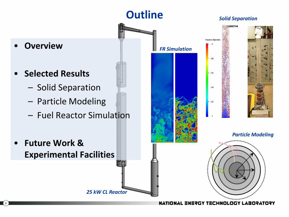
Outline
• Overview
• Selected Results
– Solid Separation
– Particle Modeling
– Fuel Reactor Simulation
• Future Work & Experimental Facilities
Solid Separation
Particle Modeling
FR Simulation
25 kW CL Reactor
3
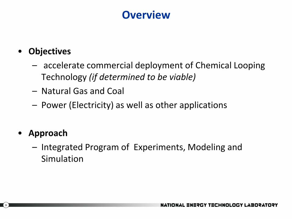
Overview
• Objectives
– accelerate commercial deployment of Chemical Looping Technology (if determined to be viable)
– Natural Gas and Coal
– Power (Electricity) as well as other applications
• Approach
– Integrated Program of Experiments, Modeling and Simulation
4
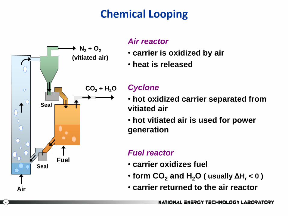
Chemical Looping
N2 + O2
(vitiated air)
CO2 + H2O
Fuel
Air
Seal
Seal
Air reactor
• carrier is oxidized by air
• heat is released
Cyclone
• hot oxidized carrier separated from
vitiated air
• hot vitiated air is used for power
generation
Fuel reactor
• carrier oxidizes fuel
• form CO2 and H2O ( usually ΔHr < 0 )
• carrier returned to the air reactor
5
CO2 + H2O
Ash
RECYCLE
CO2 + H2OFuel
Air
Seal
Seal
N2 + O2
(vitiated air)
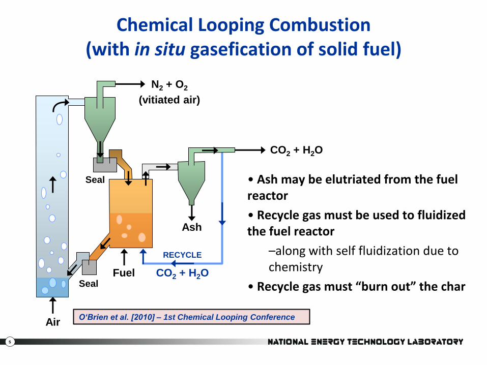
Chemical Looping Combustion(with in situ gasefication of solid fuel)
• Ash may be elutriated from the fuel reactor
• Recycle gas must be used to fluidized the fuel reactor
–along with self fluidization due to chemistry
• Recycle gas must “burn out” the char
O‘Brien et al. [2010] – 1st Chemical Looping Conference
6
Challenges
• Carrier selection
– balance carrier performance (reactivity, capacity), cost and availability
• Fuel utilization
– bypass of fuel in the bed
– gas residence time
– gasification of coal is rate limiting
• Solids Handling
– carrier, coal, ash separation
– circulation rate & inventory control
• Heat integration
– fuel reactor is endothermic
7
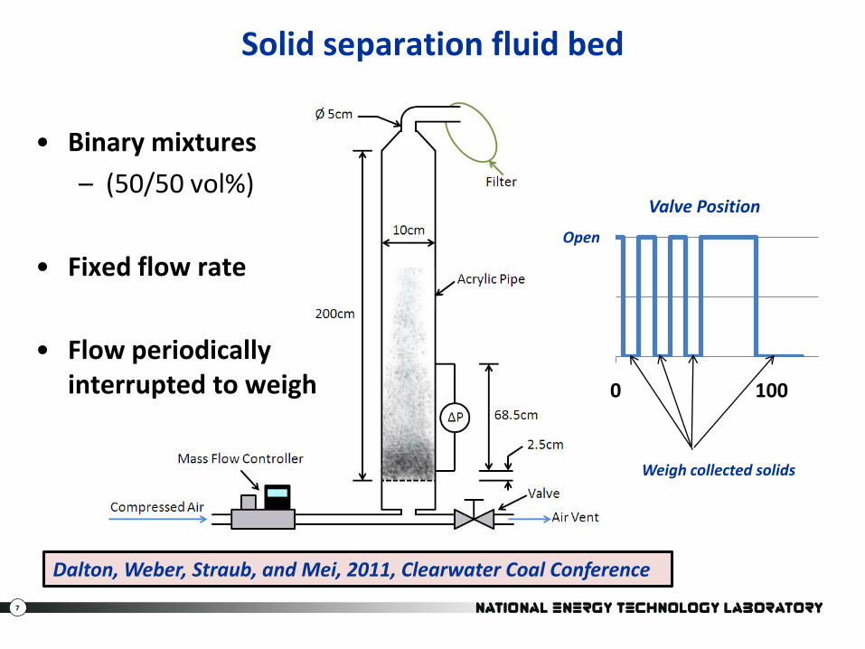
Solid separation fluid bed
• Binary mixtures
– (50/50 vol%)
• Fixed flow rate
• Flow periodically interrupted to weigh 0 100
Valve Position
Weigh collected solids
Open
Dalton, Weber, Straub, and Mei, 2011, Clearwater Coal Conference
8
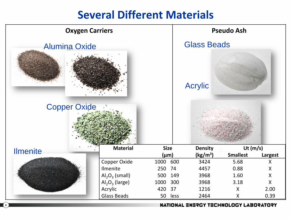
Oxygen Carriers Pseudo Ash
Several Different Materials
Alumina Oxide
Copper Oxide
Ilmenite
Glass Beads
Acrylic
Material Size Density Ut (m/s)(μm) (kg/m3) Smallest Largest
Copper Oxide 1000 600 3424 5.68 XIlmenite 250 74 4457 0.88 XAl2O3 (small) 500 149 3968 1.60 XAl2O3 (large) 1000 300 3968 3.18 XAcrylic 420 37 1216 X 2.00Glass Beads 50 less 2464 X 0.39
9
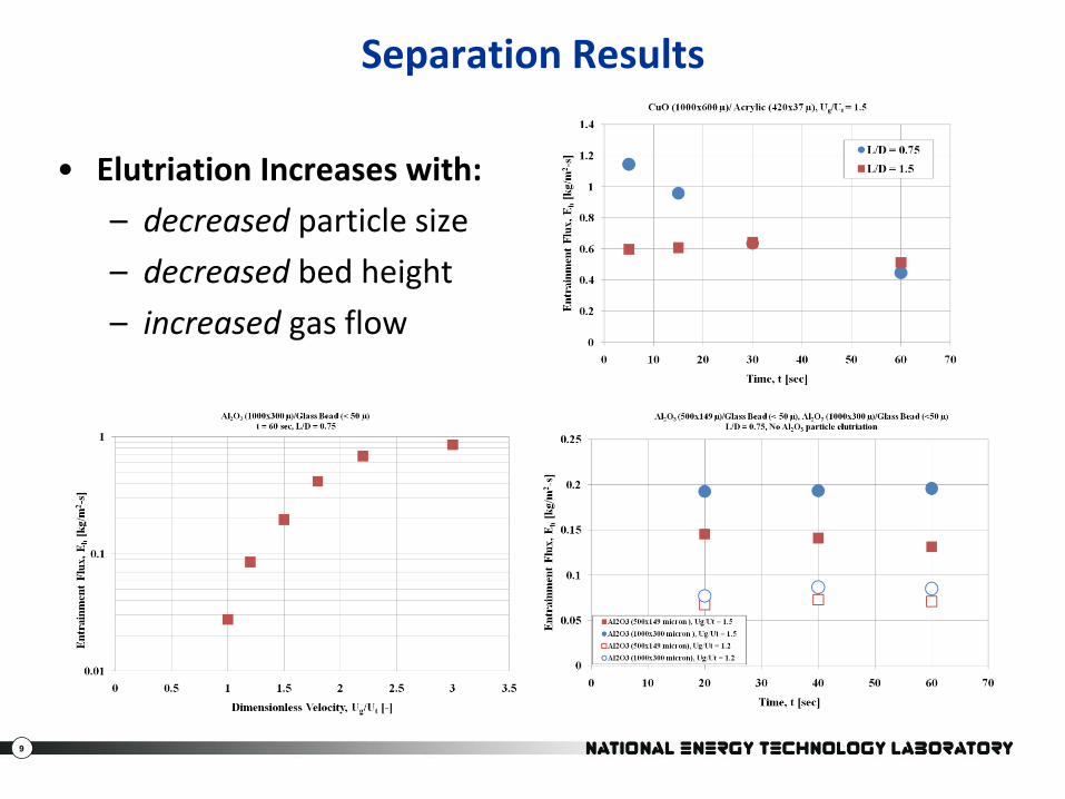
Separation Results
• Elutriation Increases with:
– decreased particle size
– decreased bed height
– increased gas flow
10
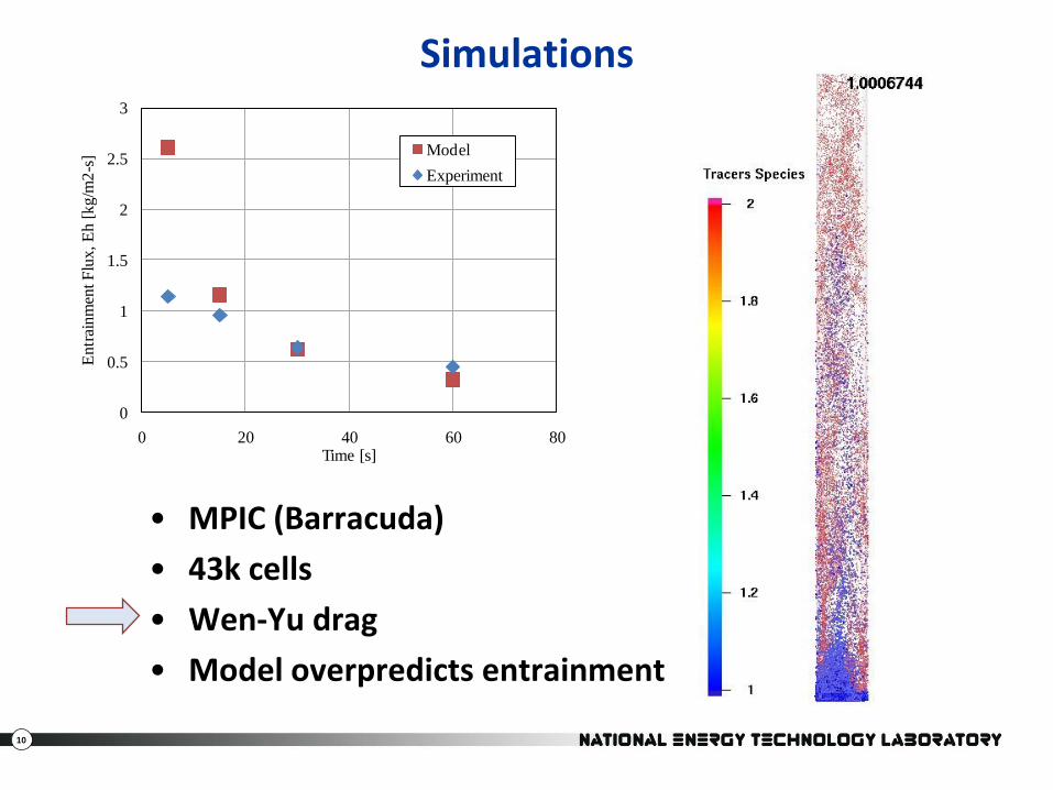
Simulations
• MPIC (Barracuda)
• 43k cells
• Wen-Yu drag
• Model overpredicts entrainment
0
0.5
1
1.5
2
2.5
3
0 20 40 60 80
En
trai
nm
ent F
lux
, E
h [
kg
/m2
-s]
Time [s]
Model
Experiment
11
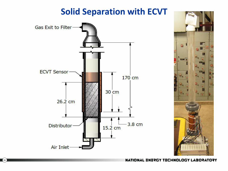
Solid Separation with ECVT
12
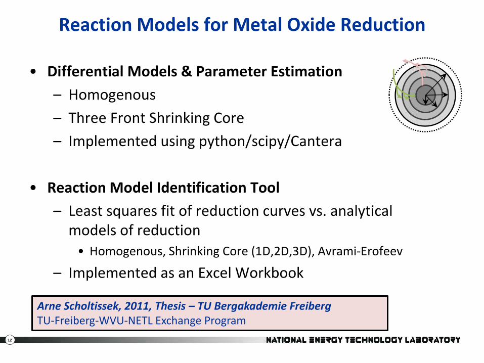
Reaction Models for Metal Oxide Reduction
• Differential Models & Parameter Estimation
– Homogenous
– Three Front Shrinking Core
– Implemented using python/scipy/Cantera
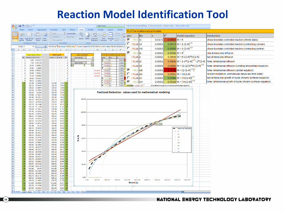
• Reaction Model Identification Tool
– Least squares fit of reduction curves vs. analytical models of reduction
• Homogenous, Shrinking Core (1D,2D,3D), Avrami-Erofeev
– Implemented as an Excel Workbook
Arne Scholtissek, 2011, Thesis – TU Bergakademie FreibergTU-Freiberg-WVU-NETL Exchange Program
13
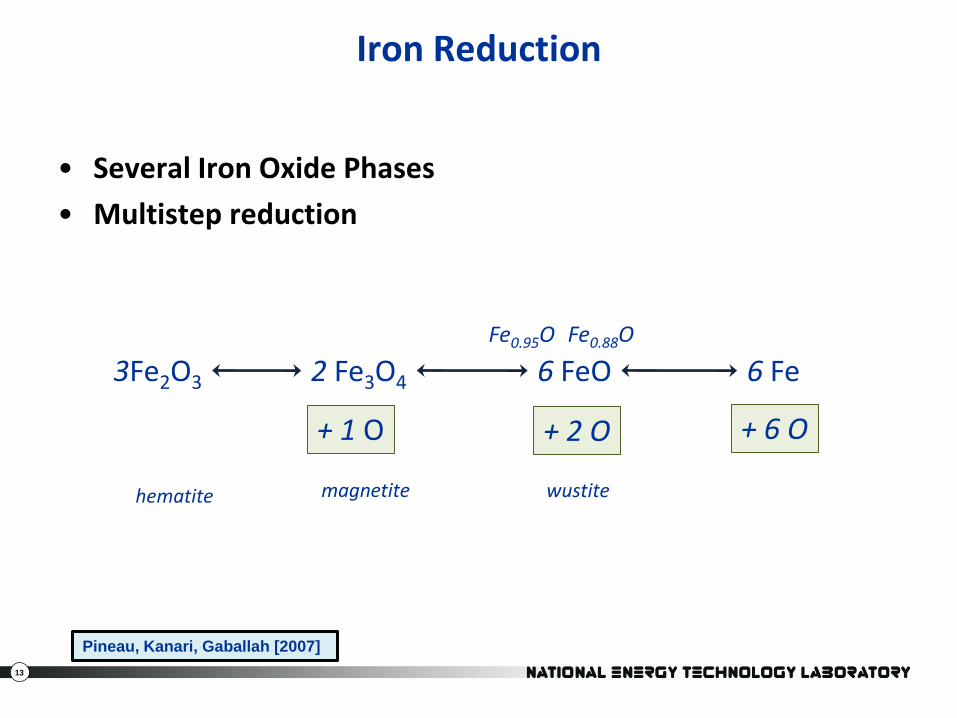
Iron Reduction
• Several Iron Oxide Phases
• Multistep reduction
Pineau, Kanari, Gaballah [2007]
3Fe2O3 2 Fe3O4 6 FeO 6 FeFe0.95O Fe0.88O
+ 1 O + 2 O + 6 O
hematite magnetite wustite
14
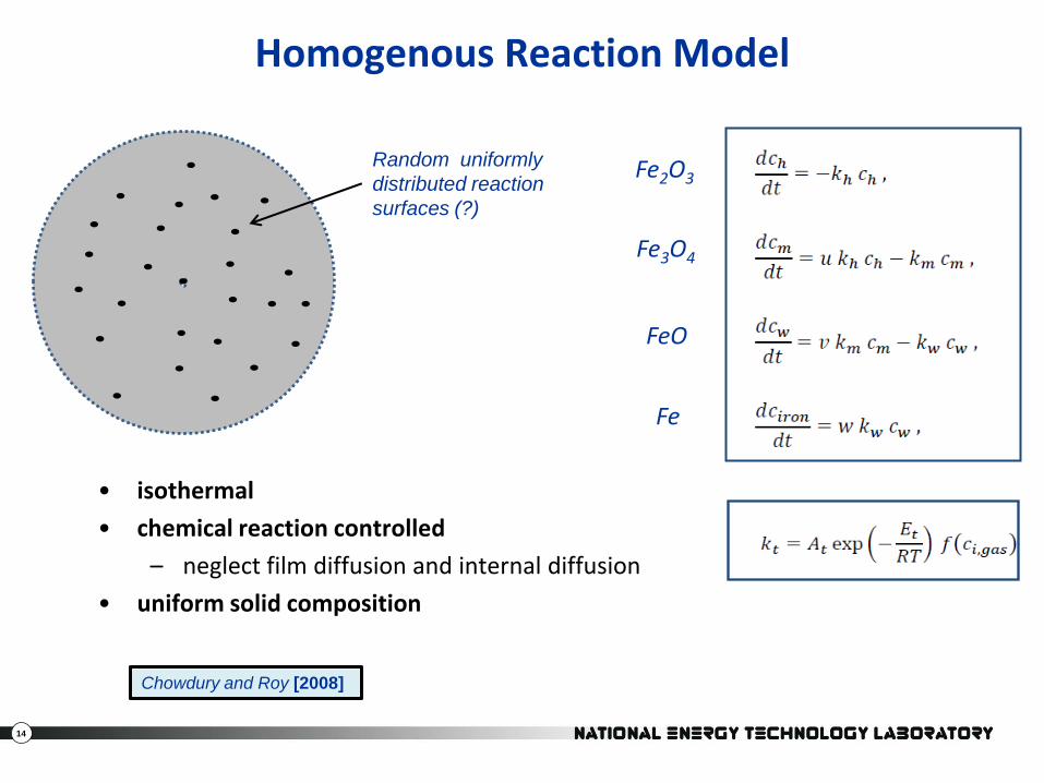
Homogenous Reaction Model
• isothermal
• chemical reaction controlled
– neglect film diffusion and internal diffusion
• uniform solid composition
Random uniformly
distributed reaction
surfaces (?)
Fe2O3
Fe3O4
FeO
Fe
Chowdury and Roy [2008]
15
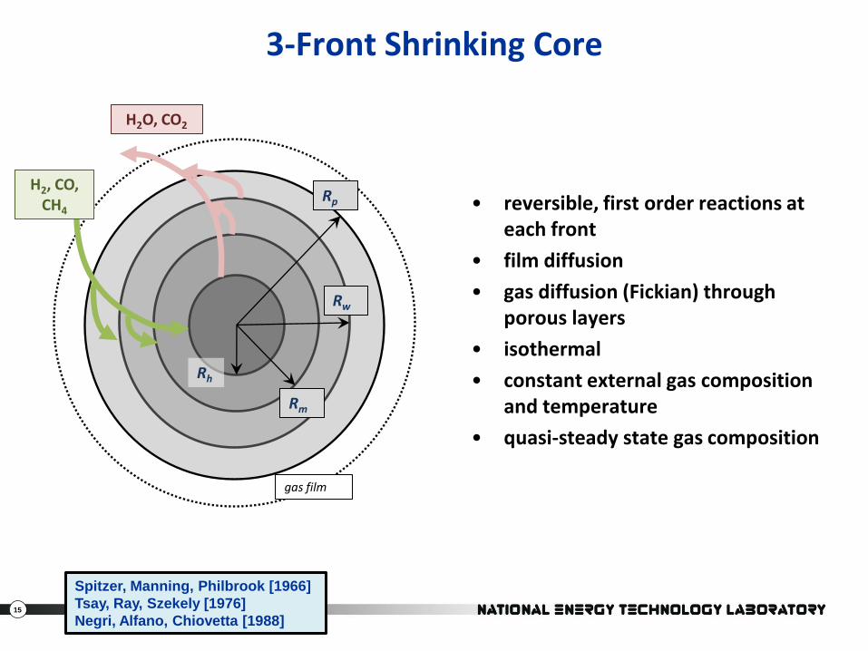
3-Front Shrinking Core
• reversible, first order reactions at each front
• film diffusion
• gas diffusion (Fickian) through porous layers
• isothermal
• constant external gas composition and temperature
• quasi-steady state gas composition
Rw
Rh
Rm
gas film
Spitzer, Manning, Philbrook [1966]
Tsay, Ray, Szekely [1976]
Negri, Alfano, Chiovetta [1988]
H2O, CO2
H2, CO, CH4
Rp
16
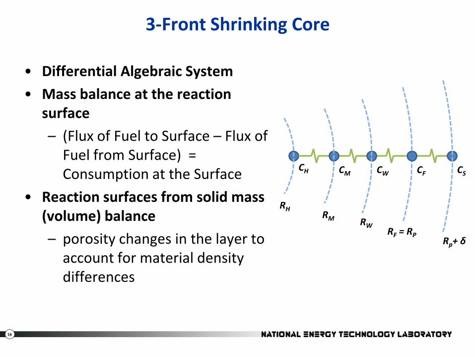
3-Front Shrinking Core
• Differential Algebraic System
• Mass balance at the reaction surface
– (Flux of Fuel to Surface – Flux of Fuel from Surface) = Consumption at the Surface
• Reaction surfaces from solid mass (volume) balance
– porosity changes in the layer to account for material density differences
CSCFCWCMCH
RHRM RW
RF = RPRp+ δ
17
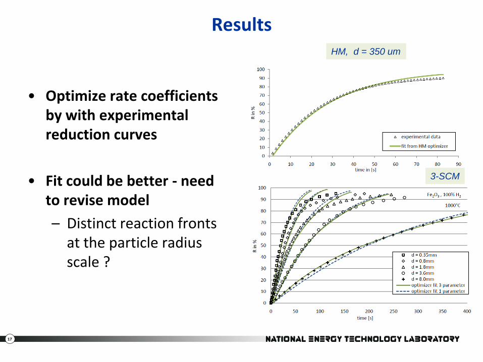
Results
• Optimize rate coefficients by with experimental reduction curves
• Fit could be better - need to revise model
– Distinct reaction fronts at the particle radius scale ?
HM, d = 350 um
3-SCM
18
Reaction Model Identification Tool
19
Fuel Reactor Simulations
• Batch Fuel Reactor
– NiO & CH4
– Jung & Gamwo [2008], Shuai et al. [2010]
• Parameter Sensitivity of a Continuous Fuel Reactor
– CuO & CO/H2
– CBIC Zaragoza – Forero et al. [2009]
• MFIX Euler-Euler
Carsten Olm, 2011, Thesis – TU Bergakademie FreibergTU-Freiberg-WVU-NETL Exchange Program
20
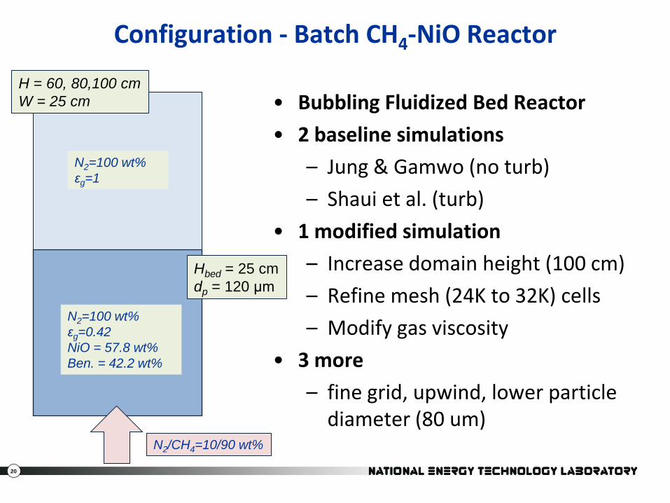
Configuration - Batch CH4-NiO Reactor
• Bubbling Fluidized Bed Reactor
• 2 baseline simulations
– Jung & Gamwo (no turb)
– Shaui et al. (turb)
• 1 modified simulation
– Increase domain height (100 cm)
– Refine mesh (24K to 32K) cells
– Modify gas viscosity
• 3 more
– fine grid, upwind, lower particle diameter (80 um)
N2=100 wt%
εg=1
N2=100 wt%
εg=0.42
NiO = 57.8 wt%
Ben. = 42.2 wt%
N2/CH4=10/90 wt%
Hbed = 25 cm
dp = 120 μm
H = 60, 80,100 cm
W = 25 cm
21
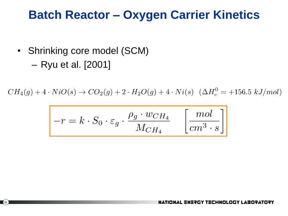
Batch Reactor – Oxygen Carrier Kinetics
• Shrinking core model (SCM)
– Ryu et al. [2001]
22
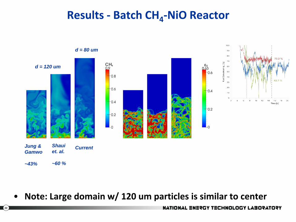
Results - Batch CH4-NiO Reactor
• Note: Large domain w/ 120 um particles is similar to center
d = 80 um
d = 120 um
Jung &
Gamwo
~43%
Shaui
et. al.
~60 %
Current
23
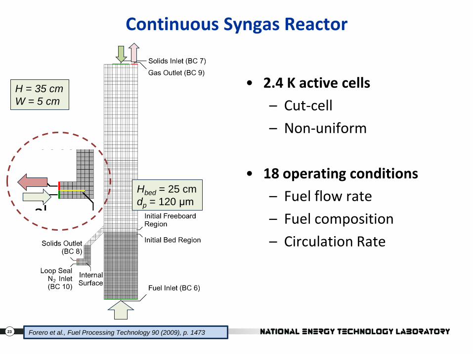
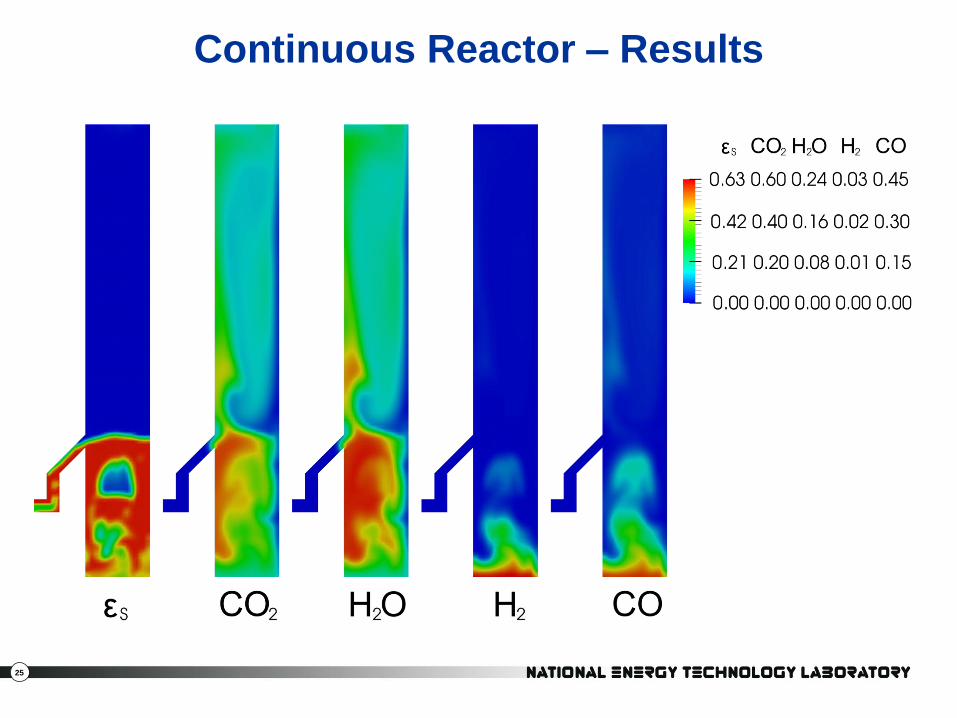
Continuous Syngas Reactor
• 2.4 K active cells
– Cut-cell
– Non-uniform
• 18 operating conditions
– Fuel flow rate
– Fuel composition
– Circulation Rate
Forero et al., Fuel Processing Technology 90 (2009), p. 1473
H = 35 cm
W = 5 cm
Hbed = 25 cm
dp = 120 μm
24
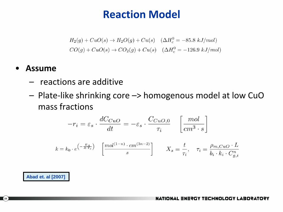
Reaction Model
• Assume
– reactions are additive
– Plate-like shrinking core –> homogenous model at low CuOmass fractions
Abad et. al [2007]
25
Continuous Reactor – Results
26
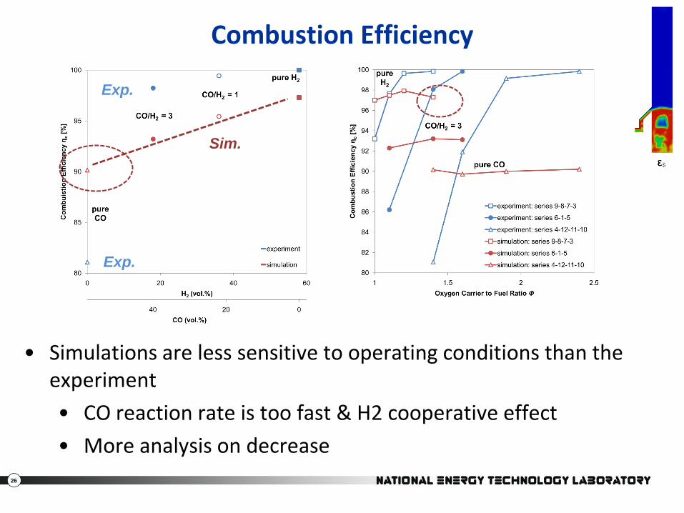
Combustion Efficiency
• Simulations are less sensitive to operating conditions than the experiment
• CO reaction rate is too fast & H2 cooperative effect
• More analysis on decrease
Exp.
Sim.
Exp.
27
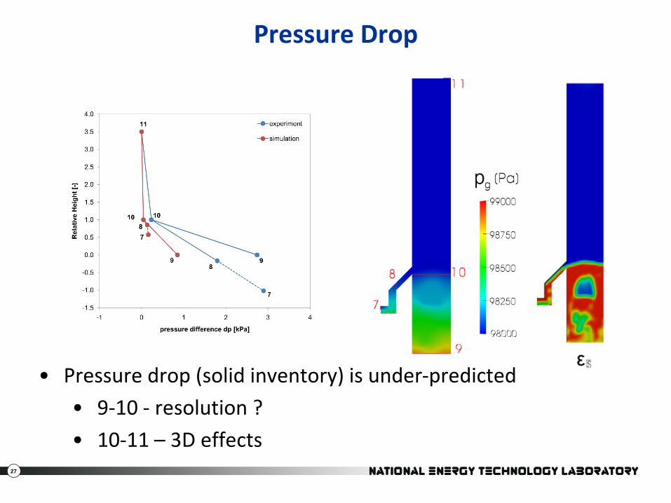
Pressure Drop
• Pressure drop (solid inventory) is under-predicted
• 9-10 - resolution ?
• 10-11 – 3D effects
28
Future Plans
• Pair experiments with simulations
– 25kW Reactor• Non-reacting (“clear”) & reacting
– Solid-separation (ECVT)
– Attrition tests
– Single Fluid Bed Reactor
• Use TGA and Fixed Bed Experiments to develop carrier specific reaction models
• Continued validation with external data
29
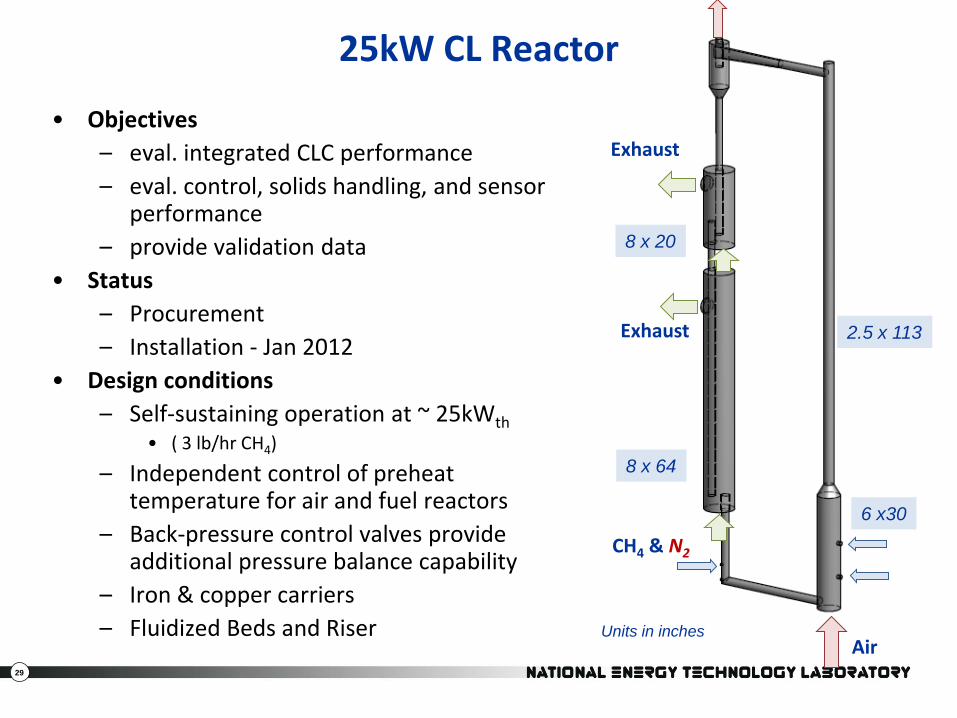
25kW CL Reactor
• Objectives
– eval. integrated CLC performance
– eval. control, solids handling, and sensor performance
– provide validation data
• Status
– Procurement
– Installation - Jan 2012
• Design conditions
– Self-sustaining operation at ~ 25kWth
• ( 3 lb/hr CH4)
– Independent control of preheat temperature for air and fuel reactors
– Back-pressure control valves provide additional pressure balance capability
– Iron & copper carriers
– Fluidized Beds and Riser
8 x 64
8 x 20
6 x30
2.5 x 113
Units in inchesAir
Exhaust
CH4 & N2
Exhaust
30
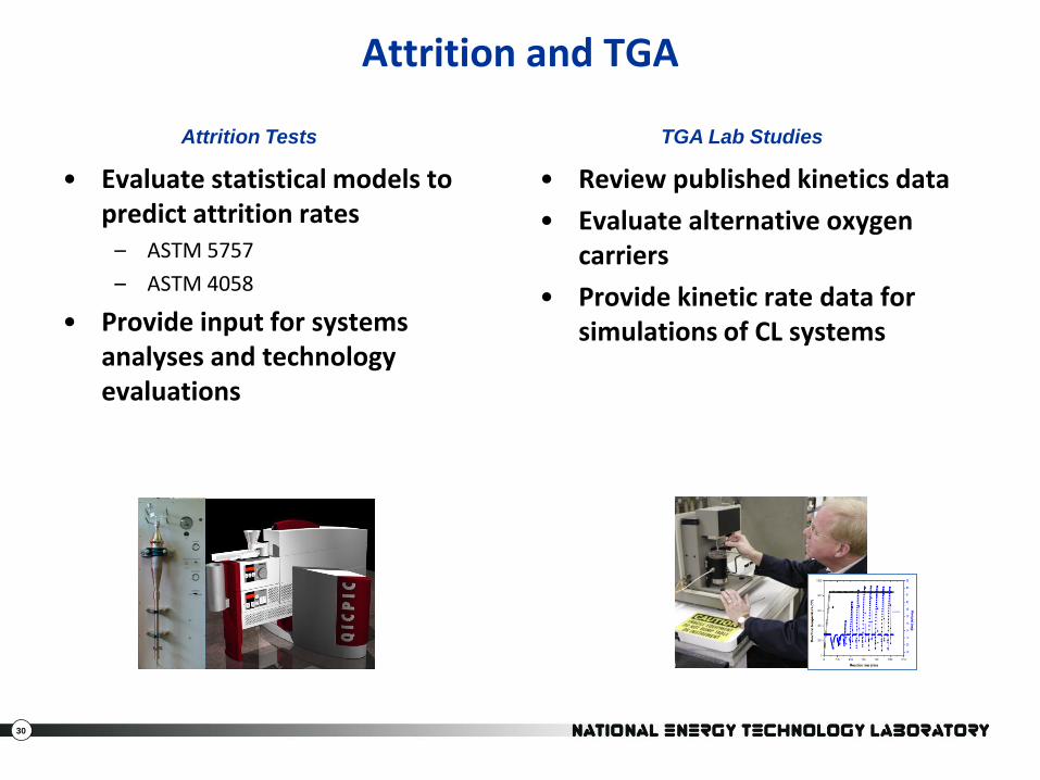
Attrition and TGA
• Evaluate statistical models to predict attrition rates
– ASTM 5757
– ASTM 4058
• Provide input for systems analyses and technology evaluations
• Review published kinetics data
• Evaluate alternative oxygen carriers
• Provide kinetic rate data for simulations of CL systems
TGA Lab StudiesAttrition Tests
31
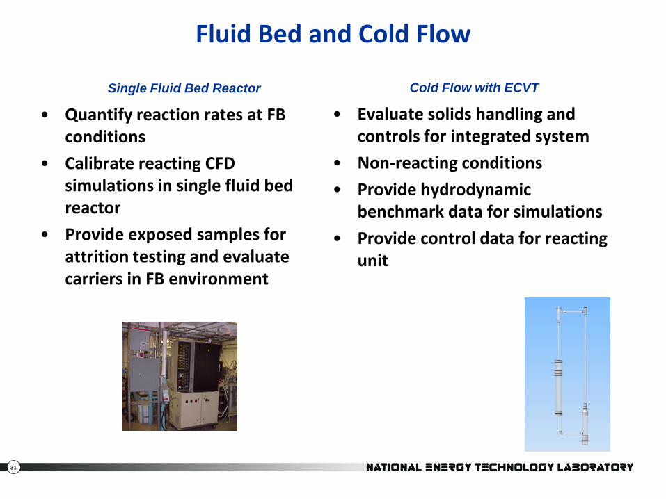
Fluid Bed and Cold Flow
• Quantify reaction rates at FB conditions
• Calibrate reacting CFD simulations in single fluid bed reactor
• Provide exposed samples for attrition testing and evaluate carriers in FB environment
Single Fluid Bed Reactor Cold Flow with ECVT
• Evaluate solids handling and controls for integrated system
• Non-reacting conditions
• Provide hydrodynamicbenchmark data for simulations
• Provide control data for reacting unit