Embed Size (px)
Citation preview
Ch
emic
al F
ixin
gs
1
Ch
emic
al fi
xin
gsGood reasons to choose fischer
2
1
Chemical fixings1
▪ Resin Performance - Introduction 3-5 ▪ Highbond-System FHB II 6 ▪ Highbond anchor FHB II-A S / FHB II-A L ▪ Powerbond injection resin FIS PM with FIS PS sleeve ▪ Superbond resin system FIS SB with RSB capsules ▪ Injection resin FIS EM ▪ Injection resin FIS EM + threaded rods for cracked concrete ▪ FIS EM + RG MI internally threaded rods for cracked concrete ▪ Resin dispenser guns ▪ R resin anchor with RG M threaded rod ▪ R resin anchor + RG M I for cracked concrete ▪ FIS V injection resin system
9141930333839404649
▪ FIS VT injection resin system 53 ▪ Resin studs for non-cracked concrete ▪ Internally threaded stud RG M I for non-cracked concrete ▪ Injection resin FIS P / FIP ▪ Injection resin in solid brick masonry ▪ Injection resin in perforated brick ▪ FIS A withinjection resin for aerated concrete ▪ Rebar connections ▪ Highbond anchor dynamic FHB dyn ▪ Fill & Fix injection fixing
556265677175788286
Ch
emical Fixin
gs
1
3
Performance of injection resins
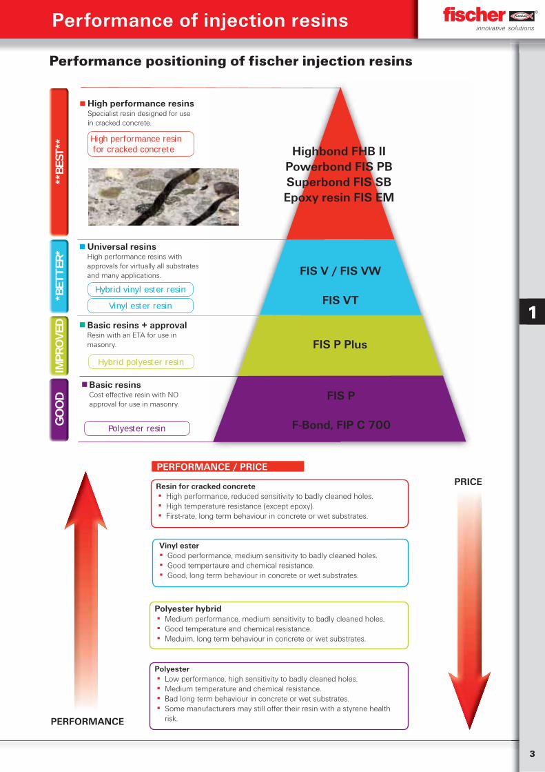
Performance positioning of fischer injection resins
High performance resin for cracked concrete
High performance resinsSpecialist resin designed for use in cracked concrete.
Universal resinsHigh performance resins with approvals for virtually all substrates and many applications.
Hybrid vinyl ester resin
Vinyl ester resin
Basic resins + approvalResin with an ETA for use in masonry.
Hybrid polyester resin
Basic resins Cost effective resin with NO approval for use in masonry.
Polyester resin
Highbond FHB IIPowerbond FIS PBSuperbond FIS SBEpoxy resin FIS EM
FIS P
F-Bond, FIP C 700
FIS P Plus
FIS V / FIS VW
FIS VT
GO
OD
IMPR
OVE
D*B
ETTE
R***
BEST
**
1
Resin for cracked concrete ▪ High performance, reduced sensitivity to badly cleaned holes. ▪ High temperature resistance (except epoxy). ▪ First-rate, long term behaviour in concrete or wet substrates.
Vinyl ester ▪ Good performance, medium sensitivity to badly cleaned holes. ▪ Good tempertaure and chemical resistance. ▪ Good, long term behaviour in concrete or wet substrates.
Polyester hybrid ▪ Medium performance, medium sensitivity to badly cleaned holes. ▪ Good temperature and chemical resistance. ▪ Meduim, long term behaviour in concrete or wet substrates.
Polyester ▪ Low performance, high sensitivity to badly cleaned holes. ▪ Medium temperature and chemical resistance. ▪ Bad long term behaviour in concrete or wet substrates. ▪ Some manufacturers may still offer their resin with a styrene health
risk.
PERFORMANCE / PRICE
PERFORMANCE
PRICE
4
Ch
emic
al fi
xin
gs
1
4
Ch
emic
al fi
xin
gsPerformance of injection resins
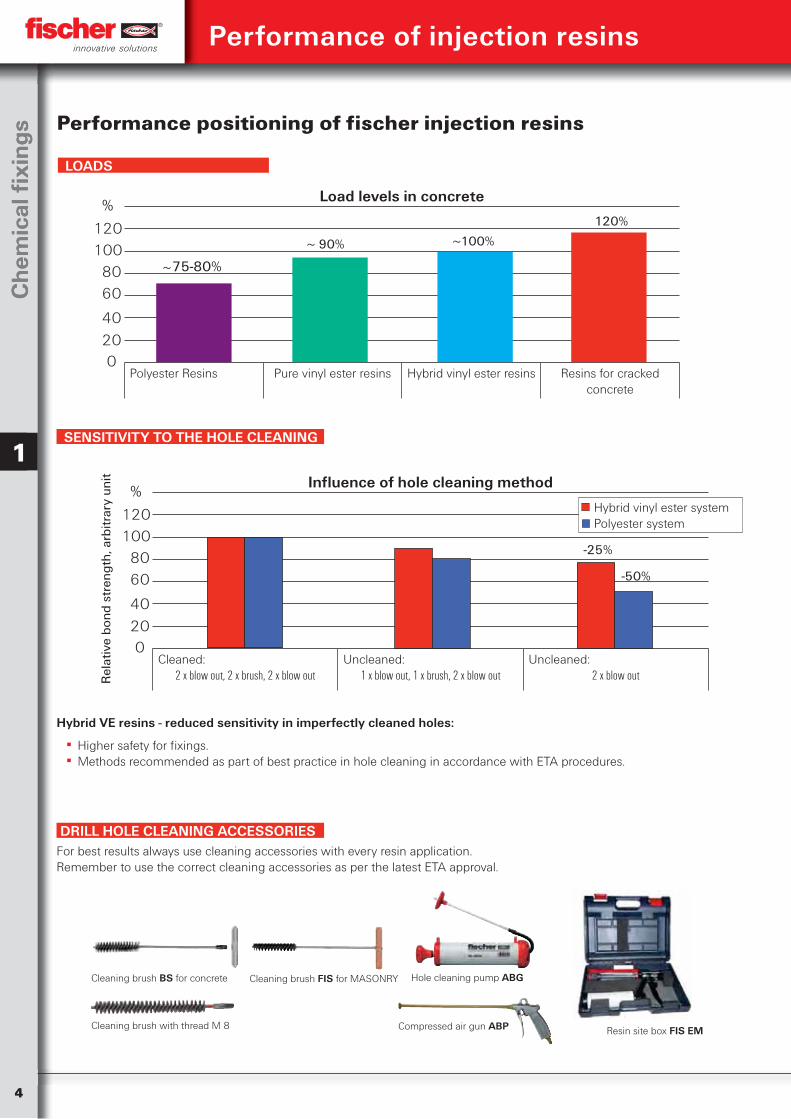
Load levels in concrete
Polyester Resins Pure vinyl ester resins Hybrid vinyl ester resins Resins for cracked concrete
02040
6080
100120
75-80%~ 90%~ 100%~
120%%
Performance positioning of fischer injection resins
SENSITIVITY TO THE HOLE CLEANING
LOADS
Influence of hole cleaning method
Cleaned:2 x blow out, 2 x brush, 2 x blow out
Uncleaned:1 x blow out, 1 x brush, 2 x blow out
Uncleaned:2 x blow out
02040
6080
100120
%
-25%
-50%
Hybrid vinyl ester systemPolyester system
Rel
ativ
e bo
nd s
tren
gth,
arb
itrar
y un
it
Hybrid VE resins - reduced sensitivity in imperfectly cleaned holes:
▪ Higher safety for fixings. ▪ Methods recommended as part of best practice in hole cleaning in accordance with ETA procedures.
DRILL HOLE CLEANING ACCESSORIES
Cleaning brush with thread M 8
Cleaning brush BS for concrete
Compressed air gun ABP
Hole cleaning pump ABGCleaning brush FIS for MASONRY
For best results always use cleaning accessories with every resin application. Remember to use the correct cleaning accessories as per the latest ETA approval.
Resin site box FIS EM
5
Ch
emical Fixin
gs
1
Performance of injection resins
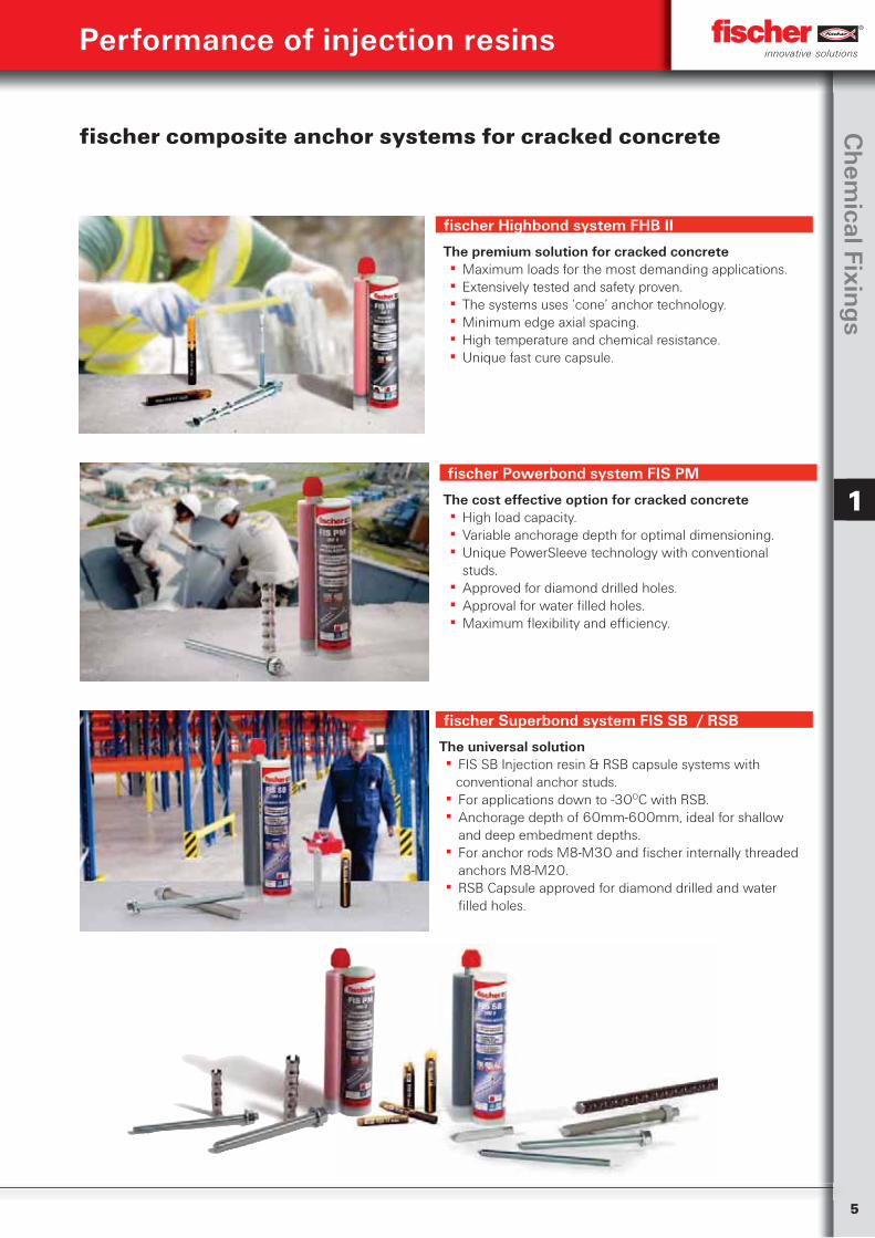
fischer composite anchor systems for cracked concrete
fischer Highbond system FHB II
The premium solution for cracked concrete ▪ Maximum loads for the most demanding applications. ▪ Extensively tested and safety proven. ▪ The systems uses ‘cone’ anchor technology. ▪ Minimum edge axial spacing. ▪ High temperature and chemical resistance. ▪ Unique fast cure capsule.
fischer Powerbond system FIS PM
The cost effective option for cracked concrete ▪ High load capacity. ▪ Variable anchorage depth for optimal dimensioning. ▪ Unique PowerSleeve technology with conventional studs.
▪ Approved for diamond drilled holes. ▪ Approval for water filled holes. ▪ Maximum flexibility and efficiency.
fischer Superbond system FIS SB / RSB
The universal solution ▪ FIS SB Injection resin & RSB capsule systems with conventional anchor studs.
▪ For applications down to -30OC with RSB. ▪ Anchorage depth of 60mm-600mm, ideal for shallow and deep embedment depths.
▪ For anchor rods M8-M30 and fischer internally threaded anchors M8-M20.
▪ RSB Capsule approved for diamond drilled and water filled holes.
6
Ch
emic
al fi
xin
gs
1
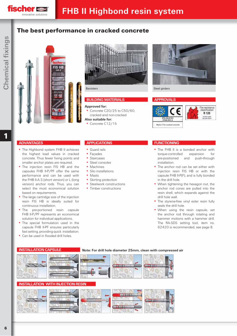
Banisters Steel girders
The best performance in cracked concrete
APPLICATIONS
▪ Guard rails ▪ Façades ▪ Staircases ▪ Steel consoles ▪ Machines ▪ Silo installations ▪ Masts ▪ Skirting protection ▪ Steelwork constructions ▪ Timber constructions
FUNCTIONING
▪ The FHB II is a bonded anchor with torque-controlled expansion for pre-positioned and push-through installation.
▪ The anchor rod can be set either with injection resin FIS HB or with the capsule FHB II-P(F), and is fully bonded in the drill hole.
▪ When tightening the hexagon nut, the anchor rod cones are pulled into the resin shell, which expands against the drill hole wall.
▪ The styrene-free vinyl ester resin fully seals the drill hole.
▪ When using the resin capsule, set the anchor rod through rotating and hammer motions with a hammer drill. The RA-SDS setting tool, item no. 62420 is recommended, see page 8.
BUILDING MATERIALS
Approved for: ▪ Concrete C20/25 to C50/60,
cracked and non-crackedAlso suitable for:
▪ Concrete C12/15
APPROVALS
ADVANTAGES
▪ The Highbond system FHB II achieves the highest load values in cracked concrete. Thus fewer fixing points and smaller anchor plates are required.
▪ The injection resin FIS HB and the capsules FHB II-P/PF offer the same performance and can be used with the FHB II-A S (short version) or L (long version) anchor rods. Thus, you can select the most economical solution based on requirements.
▪ The large cartridge size of the injection resin FIS HB is ideally suited for continuous installation.
▪ The pre-portioned resin capsule FHB II-P/PF represents an economical solution for individual applications.
▪ The special formulation used in the capsule FHB II-PF ensures particularly fast setting, providing quick installation.
▪ Can be used in flooded drill holes.
INSTALLATION CAPSULE
INSTALLATION WITH INJECTION RESIN
FHB II Highbond resin system
Note: For drill hole diameter 25mm, clean with compressed air
7
Ch
emical Fixin
gs
1
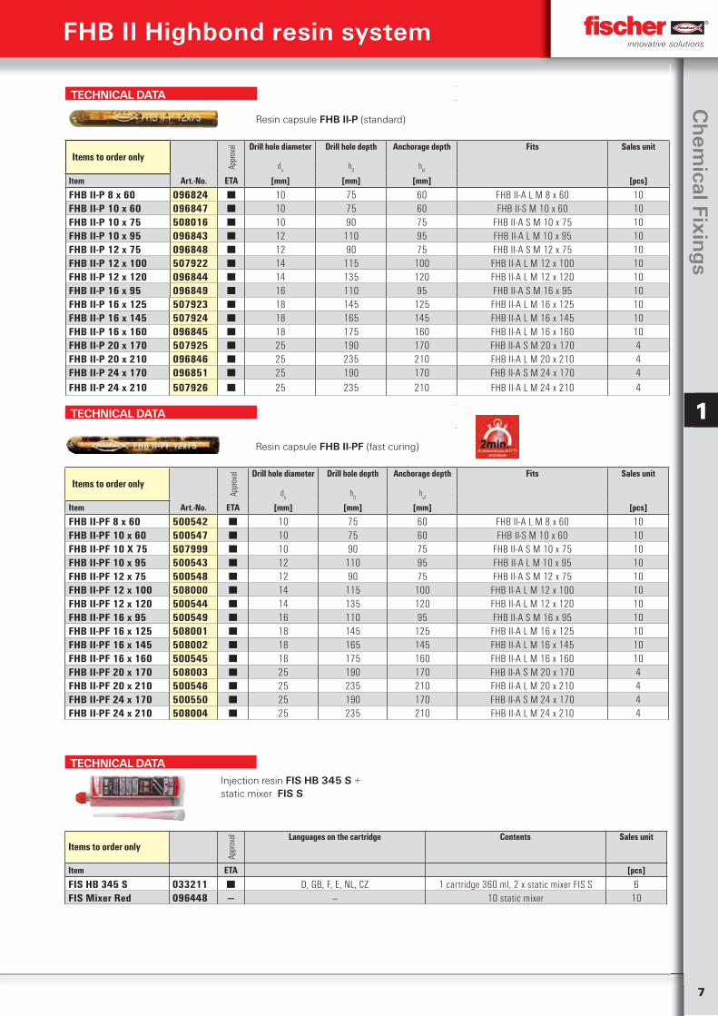
TECHNICAL DATA
Resin capsule FHB II-P (standard)
Items to order only
Appr
oval Drill hole diameter Drill hole depth Anchorage depth Fits Sales unit
do
h0
hef
Item Art.-No. ETA [mm] [mm] [mm] [pcs]
FHB II-P 8 x 60 096824 ■ 10 75 60 FHB II-A L M 8 x 60 10FHB II-P 10 x 60 096847 ■ 10 75 60 FHB II-S M 10 x 60 10FHB II-P 10 x 75 508016 ■ 10 90 75 FHB II-A S M 10 x 75 10FHB II-P 10 x 95 096843 ■ 12 110 95 FHB II-A L M 10 x 95 10FHB II-P 12 x 75 096848 ■ 12 90 75 FHB II-A S M 12 x 75 10FHB II-P 12 x 100 507922 ■ 14 115 100 FHB II-A L M 12 x 100 10FHB II-P 12 x 120 096844 ■ 14 135 120 FHB II-A L M 12 x 120 10FHB II-P 16 x 95 096849 ■ 16 110 95 FHB II-A S M 16 x 95 10FHB II-P 16 x 125 507923 ■ 18 145 125 FHB II-A L M 16 x 125 10FHB II-P 16 x 145 507924 ■ 18 165 145 FHB II-A L M 16 x 145 10FHB II-P 16 x 160 096845 ■ 18 175 160 FHB II-A L M 16 x 160 10FHB II-P 20 x 170 507925 ■ 25 190 170 FHB II-A S M 20 x 170 4FHB II-P 20 x 210 096846 ■ 25 235 210 FHB II-A L M 20 x 210 4FHB II-P 24 x 170 096851 ■ 25 190 170 FHB II-A S M 24 x 170 4FHB II-P 24 x 210 507926 ■ 25 235 210 FHB II-A L M 24 x 210 4
TECHNICAL DATA
Resin capsule FHB II-PF (fast curing)
Items to order only
Appr
oval Drill hole diameter Drill hole depth Anchorage depth Fits Sales unit
do
h0
hef
Item Art.-No. ETA [mm] [mm] [mm] [pcs]
FHB II-PF 8 x 60 500542 ■ 10 75 60 FHB II-A L M 8 x 60 10FHB II-PF 10 x 60 500547 ■ 10 75 60 FHB II-S M 10 x 60 10FHB II-PF 10 X 75 507999 ■ 10 90 75 FHB II-A S M 10 x 75 10FHB II-PF 10 x 95 500543 ■ 12 110 95 FHB II-A L M 10 x 95 10FHB II-PF 12 x 75 500548 ■ 12 90 75 FHB II-A S M 12 x 75 10FHB II-PF 12 x 100 508000 ■ 14 115 100 FHB II-A L M 12 x 100 10FHB II-PF 12 x 120 500544 ■ 14 135 120 FHB II-A L M 12 x 120 10FHB II-PF 16 x 95 500549 ■ 16 110 95 FHB II-A S M 16 x 95 10FHB II-PF 16 x 125 508001 ■ 18 145 125 FHB II-A L M 16 x 125 10FHB II-PF 16 x 145 508002 ■ 18 165 145 FHB II-A L M 16 x 145 10FHB II-PF 16 x 160 500545 ■ 18 175 160 FHB II-A L M 16 x 160 10FHB II-PF 20 x 170 508003 ■ 25 190 170 FHB II-A S M 20 x 170 4FHB II-PF 20 x 210 500546 ■ 25 235 210 FHB II-A L M 20 x 210 4FHB II-PF 24 x 170 500550 ■ 25 190 170 FHB II-A S M 24 x 170 4FHB II-PF 24 x 210 508004 ■ 25 235 210 FHB II-A L M 24 x 210 4
TECHNICAL DATAInjection resin FIS HB 345 S + static mixer FIS S
Items to order only
Appr
oval Languages on the cartridge Contents Sales unit
Item ETA [pcs]
FIS HB 345 S 033211 ■ D, GB, F, E, NL, CZ 1 cartridge 360 ml, 2 x static mixer FIS S 6FIS Mixer Red 096448 — — 10 static mixer 10
FHB II Highbond resin system
8
Ch
emic
al fi
xin
gs
1
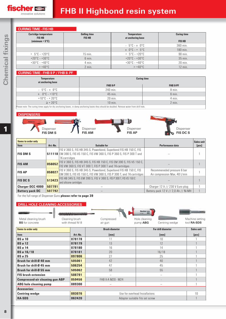
DRILL HOLE CLEANING ACCESSORIES
Items to order only Brush diameter For drill diameter Sales unit
Item Art.-No. [mm] [mm] [pcs]
BS ø 10 078178 11 10 1BS ø 12 078179 13 12 1BS ø 14 078180 16 14 1BS ø 16/18 078181 20 16/18 1BS ø 25 097806 27 25 1Brush for drill-Ø 40 mm 505061 42 40 1Brush for drill-Ø 45 mm 506254 47 45 1Brush for drill-Ø 55 mm 505062 58 55 1FIS brush extension 508791 — — 1Compressed-air cleaning gun ABP 059456 FHB II-A M20 - M24 - 1ABG hole cleaning pump 089300 — — 1Acessories:Centring wedge 093076 Use for overhead Installations 10RA-SDS 062420 Adapter suitable fits set screw 1
FHB II Highbond resin system
Cartridge temperatureFIS HB
Gelling timeFIS HB
Temperatureat anchoring base
Curing time
(minimum + 5°C) FIS HB
‒ 5°C – ± 0°C 360 min.± 0°C – + 5°C 180 min.
+ 5°C – +20°C 15 min. + 5°C – +20°C 90 min.+20°C – +30°C 6 min. +20°C – +30°C 35 min.+30°C – +40°C 4 min. +30°C – +40°C 20 min. > +40°C 2 min. > +40°C 12 min.
CURING TIME - FIS HB
Temperatureat anchoring base
Curing time
FHB II-P FHB II-PF
‒ 5°C – ± 0°C 240 min. 8 min.± 0°C – +10°C 45 min. 6 min.+10°C – + 20°C 20 min. 4 min. ≧ + 20°C 10 min. 2 min.
Please note: The curing times apply for dry anchoring bases, in damp anchoring bases they should be doubled. Remove water from drill hole.
CURING TIME - FHB II P / FHB II- PF
Cleaning brush with thread M 8
Metal cleaning brush BS for concrete
Compressed air gun
Hole cleaning pump ABG
DISPENSERS
Item Art.-No. Suitable for Performance dataSales unit
[pcs]
FIS DM S 511118FIS V 360 S, FIS HB 345 S, Powerbond, Superbond FIS HB 150 C, FIS EM 390 S, FIS VS 150 C, FIS VW 360 S, FIS P 360 S, FIS P 300 T and 1K-cartridges
— 1
FIS AM 056052FIS V 360 S, FIS HB 345 S, FIS HB 150 C, FIS EM 390 S, FIS VS 150 C, FIS VW 360 S, FIS VT 300 T, FIS P 300 T and 1K-cartridges
— 1
FIS AP 058027FIS V 360 S, FIS HB 345 S, Powerbond, Superbond FIS HB 150 C, FIS EM 390 S, FIS VS 150 C, FIS VW 360 S, FIS P 300 T, and 1K-cartridges
Recommeneded pressure 6 barAir compression Max. 40 I/min
1
FIS DC S 513423FIS HB 345 S, FIS EM 390 S, FIS V 360 S, FIS P 300 T, FIS VS 150 C and silicone cartridges
— 1
Charger DCC 4000 507791 — Charger 12 V // 230 V Euro plug 1Battery pack DC 507792 — Battery pack 12 V // 2,0 Ah // Ni-MH 1
Items to order only
DispenserFIS AM
Dispenser FIS DM S
Dispenser FIS DC S
Dispenser FIS AP
Centring wedgeMachine setting tool RA-SDS
For the full range of Dispenser Guns please refer to page 39
9
Ch
emical Fixin
gs
1
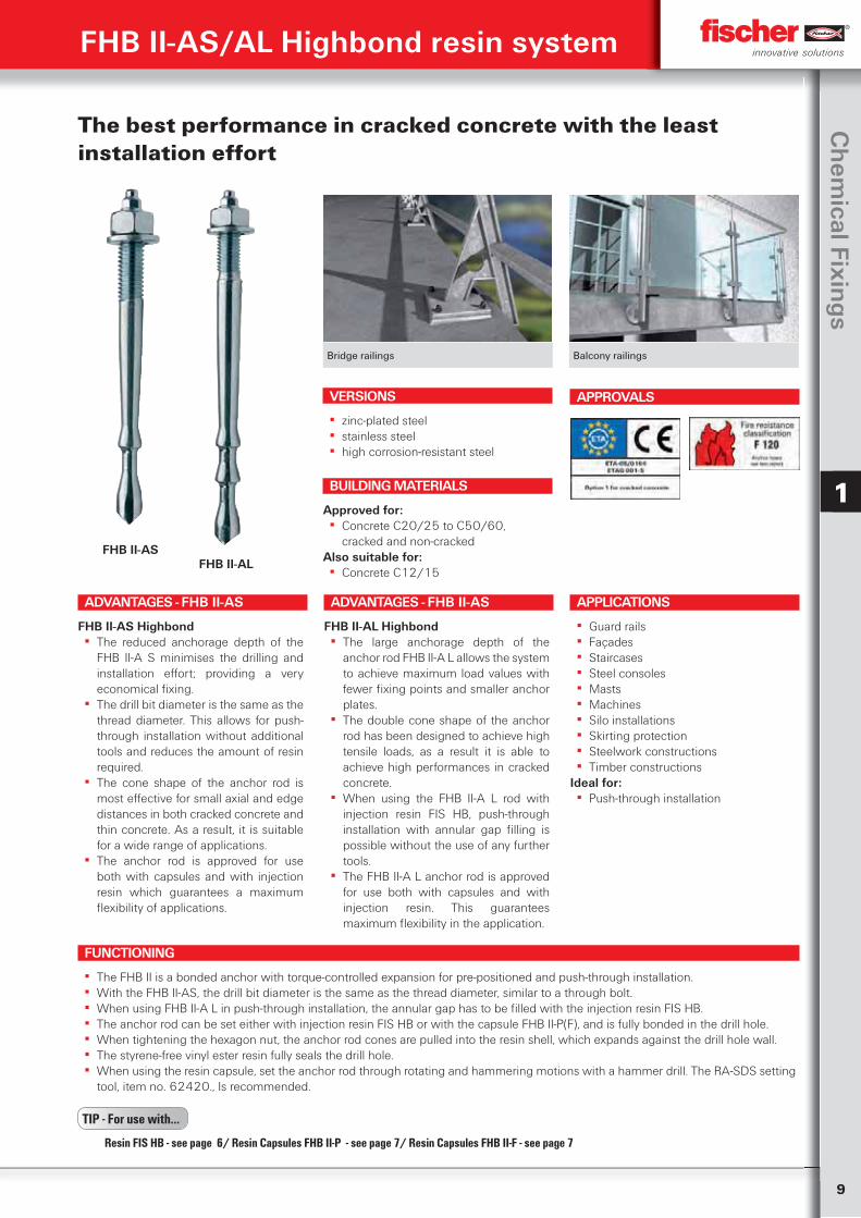
FHB II-AS/AL Highbond resin system
Bridge railings Balcony railings
The best performance in cracked concrete with the least installation effort
ADVANTAGES - FHB II-AS
FHB II-AS Highbond ▪ The reduced anchorage depth of the
FHB II-A S minimises the drilling and installation effort; providing a very economical fixing.
▪ The drill bit diameter is the same as the thread diameter. This allows for push-through installation without additional tools and reduces the amount of resin required.
▪ The cone shape of the anchor rod is most effective for small axial and edge distances in both cracked concrete and thin concrete. As a result, it is suitable for a wide range of applications.
▪ The anchor rod is approved for use both with capsules and with injection resin which guarantees a maximum flexibility of applications.
VERSIONS
▪ zinc-plated steel ▪ stainless steel ▪ high corrosion-resistant steel
APPLICATIONS
▪ Guard rails ▪ Façades ▪ Staircases ▪ Steel consoles ▪ Masts ▪ Machines ▪ Silo installations ▪ Skirting protection ▪ Steelwork constructions ▪ Timber constructions
Ideal for: ▪ Push-through installation
FUNCTIONING
▪ The FHB II is a bonded anchor with torque-controlled expansion for pre-positioned and push-through installation. ▪ With the FHB II-AS, the drill bit diameter is the same as the thread diameter, similar to a through bolt. ▪ When using FHB II-A L in push-through installation, the annular gap has to be filled with the injection resin FIS HB. ▪ The anchor rod can be set either with injection resin FIS HB or with the capsule FHB II-P(F), and is fully bonded in the drill hole. ▪ When tightening the hexagon nut, the anchor rod cones are pulled into the resin shell, which expands against the drill hole wall. ▪ The styrene-free vinyl ester resin fully seals the drill hole. ▪ When using the resin capsule, set the anchor rod through rotating and hammering motions with a hammer drill. The RA-SDS setting
tool, item no. 62420., Is recommended.
BUILDING MATERIALS
Approved for: ▪ Concrete C20/25 to C50/60,
cracked and non-crackedAlso suitable for:
▪ Concrete C12/15
APPROVALS
FHB II-AS FHB II-AL
ADVANTAGES - FHB II-AS
FHB II-AL Highbond ▪ The large anchorage depth of the
anchor rod FHB II-A L allows the system to achieve maximum load values with fewer fixing points and smaller anchor plates.
▪ The double cone shape of the anchor rod has been designed to achieve high tensile loads, as a result it is able to achieve high performances in cracked concrete.
▪ When using the FHB II-A L rod with injection resin FIS HB, push-through installation with annular gap filling is possible without the use of any further tools.
▪ The FHB II-A L anchor rod is approved for use both with capsules and with injection resin. This guarantees maximum flexibility in the application.
Resin FIS HB - see page 6/ Resin Capsules FHB II-P - see page 7/ Resin Capsules FHB II-F - see page 7
TIP - For use with...
10
Ch
emic
al fi
xin
gs
1
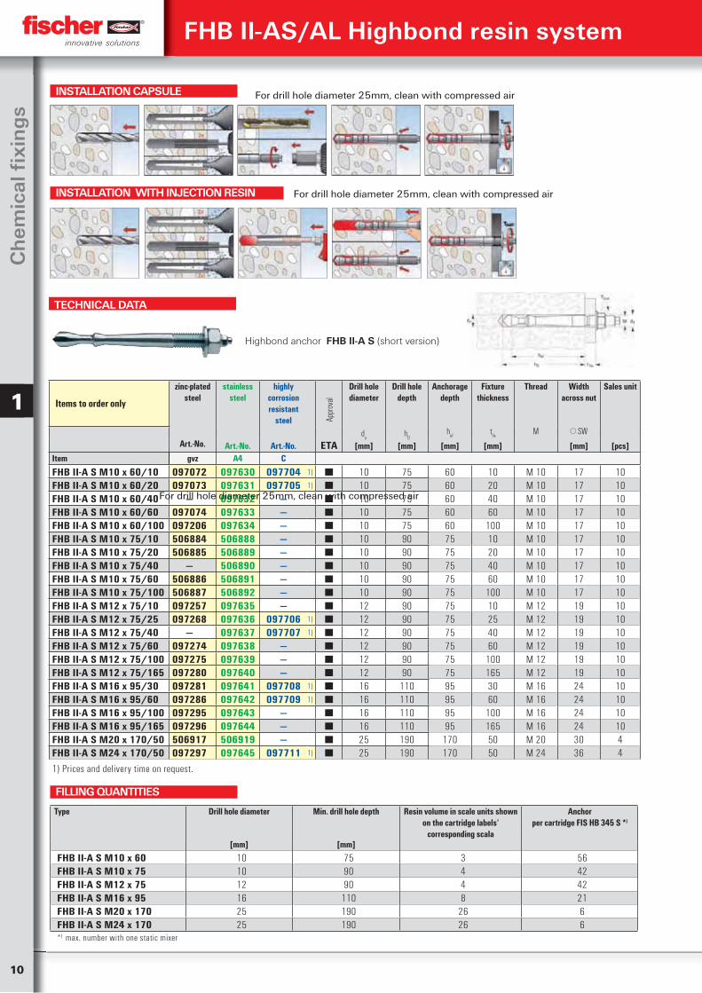
TECHNICAL DATA
Highbond anchor FHB II-A S (short version)
Items to order only
zinc-plated steel
stainless steel
highly corrosion resistant
steel Appr
oval
Drill hole diameter
Drill hole depth
Anchorage depth
Fixture thickness
Thread Width across nut
Sales unit
Art.-No.d
oh
0h
eft
fixM SW
Art.-No. Art.-No. ETA [mm] [mm] [mm] [mm] [mm] [pcs]Item gvz A4 C
FHB II-A S M10 x 60/10 097072 097630 097704 1) ■ 10 75 60 10 M 10 17 10FHB II-A S M10 x 60/20 097073 097631 097705 1) ■ 10 75 60 20 M 10 17 10FHB II-A S M10 x 60/40 — 097632 — ■ 10 75 60 40 M 10 17 10FHB II-A S M10 x 60/60 097074 097633 — ■ 10 75 60 60 M 10 17 10FHB II-A S M10 x 60/100 097206 097634 — ■ 10 75 60 100 M 10 17 10FHB II-A S M10 x 75/10 506884 506888 — ■ 10 90 75 10 M 10 17 10FHB II-A S M10 x 75/20 506885 506889 — ■ 10 90 75 20 M 10 17 10FHB II-A S M10 x 75/40 — 506890 — ■ 10 90 75 40 M 10 17 10FHB II-A S M10 x 75/60 506886 506891 — ■ 10 90 75 60 M 10 17 10FHB II-A S M10 x 75/100 506887 506892 — ■ 10 90 75 100 M 10 17 10FHB II-A S M12 x 75/10 097257 097635 — ■ 12 90 75 10 M 12 19 10FHB II-A S M12 x 75/25 097268 097636 097706 1) ■ 12 90 75 25 M 12 19 10FHB II-A S M12 x 75/40 — 097637 097707 1) ■ 12 90 75 40 M 12 19 10FHB II-A S M12 x 75/60 097274 097638 — ■ 12 90 75 60 M 12 19 10FHB II-A S M12 x 75/100 097275 097639 — ■ 12 90 75 100 M 12 19 10FHB II-A S M12 x 75/165 097280 097640 — ■ 12 90 75 165 M 12 19 10FHB II-A S M16 x 95/30 097281 097641 097708 1) ■ 16 110 95 30 M 16 24 10FHB II-A S M16 x 95/60 097286 097642 097709 1) ■ 16 110 95 60 M 16 24 10FHB II-A S M16 x 95/100 097295 097643 — ■ 16 110 95 100 M 16 24 10FHB II-A S M16 x 95/165 097296 097644 — ■ 16 110 95 165 M 16 24 10FHB II-A S M20 x 170/50 506917 506919 — ■ 25 190 170 50 M 20 30 4FHB II-A S M24 x 170/50 097297 097645 097711 1) ■ 25 190 170 50 M 24 36 4
1) Prices and delivery time on request.
Type Drill hole diameter Min. drill hole depth Resin volume in scale units shown on the cartridge labels‘
corresponding scala
Anchorper cartridge FIS HB 345 S *)
[mm] [mm]
FHB II-A S M10 x 60 10 75 3 56FHB II-A S M10 x 75 10 90 4 42FHB II-A S M12 x 75 12 90 4 42FHB II-A S M16 x 95 16 110 8 21FHB II-A S M20 x 170 25 190 26 6FHB II-A S M24 x 170 25 190 26 6*) max. number with one static mixer
FILLING QUANTITIES
INSTALLATION CAPSULE
INSTALLATION WITH INJECTION RESIN
FHB II-AS/AL Highbond resin system
For drill hole diameter 25mm, clean with compressed air
For drill hole diameter 25mm, clean with compressed air
For drill hole diameter 25mm, clean with compressed air
11
Ch
emical Fixin
gs
1
FHB II-AS/AL Highbond resin system
TECHNICAL DATA
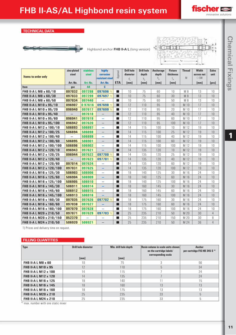
Highbond anchor FHB II-A L (long version)
Items to order only
zinc-plated steel
stainless steel
highly corrosion
resistant steel Appr
oval Drill hole
diameterDrill hole
depthAnchorage
depthFixture
thicknessThread Width
across nutSales unit
do
h0
hef
tfix
M SW Art.-No. Art.-No. Art.-No. ETA [mm] [mm] [mm] [mm] [mm] [pcs]
Item gvz A4 C
FHB II-A L M8 x 60/10 097032 097298 097696 1) ■ 10 75 60 10 M 8 13 10FHB II-A L M8 x 60/30 097033 097299 097697 1) ■ 10 75 60 30 M 8 13 10FHB II-A L M8 x 60/50 097034 097440 — ■ 10 75 60 50 M 8 13 10FHB II-A L M10 x 95/10 096907 0 97616 097698 1) ■ 12 110 95 10 M 10 17 10FHB II-A L M10 x 95/20 096940 097617 097699 1) ■ 12 110 95 20 M 10 17 10FHB II-A L M10 x 95/40 — 097618 — ■ 12 110 95 40 M 10 17 10FHB II-A L M10 x 95/60 096941 097619 — ■ 12 110 95 60 M 10 17 10FHB II-A L M10 x 95/100 096942 097620 — ■ 12 110 95 100 M 10 17 10FHB II-A L M12 x 100/10 506893 506897 — ■ 14 115 100 10 M 12 19 10FHB II-A L M12 x 100/25 506894 506898 — ■ 14 115 100 25 M 12 19 10FHB II-A L M12 x 100/40 — 506899 — ■ 14 115 100 40 M 12 19 10FHB II-A L M12 x 100/60 506895 506901 — ■ 14 115 100 60 M 12 19 10FHB II-A L M12 x 100/100 506896 506902 — ■ 14 115 100 100 M 12 19 10FHB II-A L M12 x 120/10 096943 097621 — ■ 14 135 120 10 M 12 19 10FHB II-A L M12 x 120/25 096944 097622 097700 1) ■ 14 135 120 25 M 12 19 10FHB II-A L M12 x 120/40 — 097623 097701 1) ■ 14 135 120 40 M 12 19 10FHB II-A L M12 x 120/60 097014 097624 — ■ 14 135 120 60 M 12 19 10FHB II-A L M12 x 120/100 097031 097625 — ■ 14 135 120 100 M 12 19 10FHB II-A L M16 x 125/30 506903 506906 — ■ 18 140 125 30 M 16 24 10FHB II-A L M16 x 125/60 506904 506909 — ■ 18 140 125 60 M 16 24 10FHB II-A L M16 x 125/100 506905 506910 — ■ 18 140 125 100 M 16 24 10FHB II-A L M16 x 145/30 506911 506914 — ■ 18 160 145 30 M 16 24 10FHB II-A L M16 x 145/60 506912 506915 — ■ 18 160 145 60 M 16 24 10FHB II-A L M16 x 145/100 506913 506916 — ■ 18 160 145 100 M 16 24 10FHB II-A L M16 x 160/30 097035 097626 097702 1) ■ 18 175 160 30 M 16 24 10FHB II-A L M16 x 160/60 097038 097627 — ■ 18 175 160 60 M 16 24 10FHB II-A L M16 x 160/100 097070 097628 — ■ 18 175 160 100 M 16 24 10FHB II-A L M20 x 210/50 097071 097629 097703 1) ■ 25 235 210 50 M 20 30 4FHB II-A L M20 x 210/150 052370 — — ■ 25 235 210 150 M 20 30 8FHB II-A L M24 x 210/50 506920 506921 — ■ 25 235 210 50 M 24 36 4
1) Prices and delivery time on request.
Type Drill hole diameter Min. drill hole depth Resin volume in scale units shown on the cartridge labels‘
corresponding scala
Anchorper cartridge FIS HB 345 S *)
[mm] [mm]
FHB II-A L M8 x 60 10 75 3 56FHB II-A L M10 x 95 12 110 5 34FHB II-A L M12 x 100 14 115 7 24FHB II-A L M12 x 120 14 135 7 24FHB II-A L M16 x 125 18 140 11 15FHB II-A L M16 x 145 18 160 13 13FHB II-A L M16 x 160 18 175 13 13FHB II-A L M20 x 210 25 235 33 5FHB II-A L M24 x 210 25 235 33 5
*) max. number with one static mixer
FILLING QUANTITIES
12
Ch
emic
al fi
xin
gs
1
FHB II-AS/AL Highbond resin system
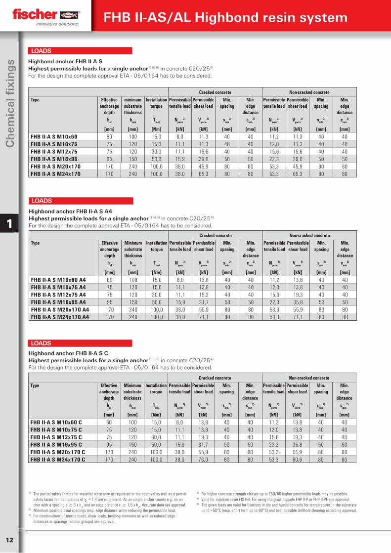
1) The partial safety factors for material resistance as regulated in the approval as well as a partial safety factor for load actions of
L = 1,4 are considered. As an single anchor counts e.g. an an-
chor with a spacing s 3 x hef and an edge distance c 1,5 x h
ef. Accurate data see approval.
2) Minimum possible axial spacings resp. edge distance while reducing the permissible load.3) For combinations of tensile loads, shear loads, bending moments as well as reduced edge
distances or spacings (anchor groups) see approval.
4) For higher concrete strength classes up to C50/60 higher permissible loads may be possible.5) Valid for injection resin FIS HB. For using the glass capsule FHP II-P or FHP II-PF see approval.6) The given loads are valid for fixations in dry and humid concrete for temperatures in the substrate
up to +50°C (resp. short term up to 80°C) and best possible drillhole cleaning according approval.
Cracked concrete Non-cracked concreteType Effective
anchorage depth
minimum substrate thickness
Installation torque
Permissible tensile load
Permissible shear load
Min.spacing
Min.edge
distance
Permissible tensile load
Permissible shear load
Min.spacing
Min.edge
distancehef hmin Tinst Nperm
3) Vperm3) smin
2) cmin2) Nperm
3) Vperm3) smin
2) cmin2)
[mm] [mm] [Nm] [kN] [kN] [mm] [mm] [kN] [kN] [mm] [mm]
FHB II-A S M10x60 60 100 15,0 8,0 11,3 40 40 11,2 11,3 40 40FHB II-A S M10x75 75 120 15,0 11,1 11,3 40 40 12,0 11,3 40 40FHB II-A S M12x75 75 120 30,0 11,1 15,6 40 40 15,6 15,6 40 40FHB II-A S M16x95 95 150 50,0 15,9 29,0 50 50 22,3 29,0 50 50FHB II-A S M20x170 170 240 100,0 38,0 45,9 80 80 53,3 45,9 80 80FHB II-A S M24x170 170 240 100,0 38,0 65,3 80 80 53,3 65,3 80 80
Highbond anchor FHB II-A SHighest permissible loads for a single anchor1) 5) 6) in concrete C20/254)
For the design the complete approval ETA - 05/0164 has to be considered.
LOADS
Cracked concrete Non-cracked concreteType Effective
anchorage depth
Minimum substrate thickness
Installation torque
Permissible tensile load
Permissible shear load
Min.spacing
Min.edge
distance
Permissible tensile load
Permissible shear load
Min.spacing
Min.edge
distancehef hmin Tinst Nperm
3) Vperm3) smin
2) cmin2) Nperm
3) Vperm3) smin
2) cmin2)
[mm] [mm] [Nm] [kN] [kN] [mm] [mm] [kN] [kN] [mm] [mm]
FHB II-A S M10x60 A4 60 100 15,0 8,0 13,8 40 40 11,2 13,8 40 40FHB II-A S M10x75 A4 75 120 15,0 11,1 13,8 40 40 12,0 13,8 40 40FHB II-A S M12x75 A4 75 120 30,0 11,1 19,3 40 40 15,6 19,3 40 40FHB II-A S M16x95 A4 95 150 50,0 15,9 31,7 50 50 22,3 35,8 50 50FHB II-A S M20x170 A4 170 240 100,0 38,0 55,9 80 80 53,3 55,9 80 80FHB II-A S M24x170 A4 170 240 100,0 38,0 71,1 80 80 53,3 71,1 80 80
Highbond anchor FHB II-A S A4Highest permissible loads for a single anchor1) 5) 6) in concrete C20/254)
For the design the complete approval ETA - 05/0164 has to be considered.
LOADS
Cracked concrete Non-cracked concreteType Effective
anchorage depth
Minimum substrate thickness
Installation torque
Permissible tensile load
Permissible shear load
Min.spacing
Min.edge
distance
Permissible tensile load
Permissible shear load
Min.spacing
Min.edge
distancehef hmin Tinst Nperm
3) Vperm3) smin
2) cmin2) Nperm
3) Vperm3) smin
2) cmin2)
[mm] [mm] [Nm] [kN] [kN] [mm] [mm] [kN] [kN] [mm] [mm]
FHB II-A S M10x60 C 60 100 15,0 8,0 13,8 40 40 11,2 13,8 40 40FHB II-A S M10x75 C 75 120 15,0 11,1 13,8 40 40 12,0 13,8 40 40FHB II-A S M12x75 C 75 120 30,0 11,1 19,3 40 40 15,6 19,3 40 40FHB II-A S M16x95 C 95 150 50,0 15,9 31,7 50 50 22,3 35,8 50 50FHB II-A S M20x170 C 170 240 100,0 38,0 55,9 80 80 53,3 55,9 80 80FHB II-A S M24x170 C 170 240 100,0 38,0 76,0 80 80 53,3 80,6 80 80
Highbond anchor FHB II-A S CHighest permissible loads for a single anchor1) 5) 6) in concrete C20/254)
For the design the complete approval ETA - 05/0164 has to be considered.
LOADS
13
Ch
emical Fixin
gs
1
Cracked concrete Non-cracked concreteType Effective
anchorage depth
Minimum substrate thickness
Installation torque
Permissible tensile load
Permissible shear load
Min.spacing
Min.edge
distance
Permissible tensile load
Permissible shear load
Min.spacing
Min.edge
distancehef hmin Tinst Nperm
3) Vperm3) smin
2) cmin2) Nperm
3) Vperm3) smin
2) cmin2)
[mm] [mm] [Nm] [kN] [kN] [mm] [mm] [kN] [kN] [mm] [mm]
FHB II-A L M8x60 60 100 15,0 8,0 7,8 40 40 11,2 7,8 40 40FHB II-A L M10x95 95 140 20,0 15,9 11,9 40 40 16,4 11,9 40 40FHB II-A L M12x100 100 140 40,0 17,1 17,3 50 50 23,7 17,3 50 50FHB II-A L M12x120 120 170 40,0 22,5 17,3 50 50 23,7 17,3 50 50FHB II-A L M16x125 125 170 60,0 24,0 32,2 55 55 33,6 32,2 55 55FHB II-A L M16x145 145 190 60,0 29,9 32,2 60 60 42,0 32,2 60 60FHB II-A L M16x160 160 220 60,0 34,7 32,2 70 70 46,0 32,2 70 70FHB II-A L M20x210 210 280 100,0 52,2 50,2 90 90 65,5 50,2 90 90FHB II-A L M24x210 210 280 100,0 52,2 72,5 90 90 65,5 72,5 90 90
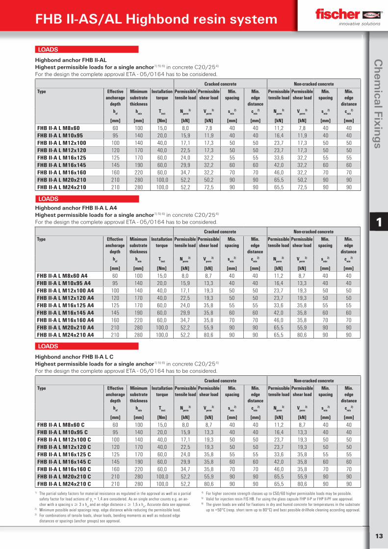
Highbond anchor FHB II-ALHighest permissible loads for a single anchor1) 5) 6) in concrete C20/254)
For the design the complete approval ETA - 05/0164 has to be considered.
LOADS
1) The partial safety factors for material resistance as regulated in the approval as well as a partial safety factor for load actions of
L = 1,4 are considered. As an single anchor counts e.g. an an-
chor with a spacing s 3 x hef and an edge distance c 1,5 x h
ef. Accurate data see approval.
2) Minimum possible axial spacings resp. edge distance while reducing the permissible load.3) For combinations of tensile loads, shear loads, bending moments as well as reduced edge
distances or spacings (anchor groups) see approval.
4) For higher concrete strength classes up to C50/60 higher permissible loads may be possible.5) Valid for injection resin FIS HB. For using the glass capsule FHP II-P or FHP II-PF see approval.6) The given loads are valid for fixations in dry and humid concrete for temperatures in the substrate
up to +50°C (resp. short term up to 80°C) and best possible drillhole cleaning according approval.
Cracked concrete Non-cracked concreteType Effective
anchorage depth
Minimum substrate thickness
Installation torque
Permissible tensile load
Permissible shear load
Min.spacing
Min.edge
distance
Permissible tensile load
Permissible shear load
Min.spacing
Min.edge
distancehef hmin Tinst Nperm
3) Vperm3) smin
2) cmin2) Nperm
3) Vperm3) smin
2) cmin2)
[mm] [mm] [Nm] [kN] [kN] [mm] [mm] [kN] [kN] [mm] [mm]
FHB II-A L M8x60 C 60 100 15,0 8,0 8,7 40 40 11,2 8,7 40 40FHB II-A L M10x95 C 95 140 20,0 15,9 13,3 40 40 16,4 13,3 40 40FHB II-A L M12x100 C 100 140 40,0 17,1 19,3 50 50 23,7 19,3 50 50FHB II-A L M12x120 C 120 170 40,0 22,5 19,3 50 50 23,7 19,3 50 50FHB II-A L M16x125 C 125 170 60,0 24,0 35,8 55 55 33,6 35,8 55 55FHB II-A L M16x145 C 145 190 60,0 29,9 35,8 60 60 42,0 35,8 60 60FHB II-A L M16x160 C 160 220 60,0 34,7 35,8 70 70 46,0 35,8 70 70FHB II-A L M20x210 C 210 280 100,0 52,2 55,9 90 90 65,5 55,9 90 90FHB II-A L M24x210 C 210 280 100,0 52,2 80,6 90 90 65,5 80,6 90 90
Highbond anchor FHB II-A L CHighest permissible loads for a single anchor1) 5) 6) in concrete C20/254)
For the design the complete approval ETA - 05/0164 has to be considered.
LOADS
Cracked concrete Non-cracked concreteType Effective
anchorage depth
Minimum substrate thickness
Installation torque
Permissible tensile load
Permissible shear load
Min.spacing
Min.edge
distance
Permissible tensile load
Permissible shear load
Min.spacing
Min.edge
distancehef hmin Tinst Nperm
3) Vperm3) smin
2) cmin2) Nperm
3) Vperm3) smin
2) cmin2)
[mm] [mm] [Nm] [kN] [kN] [mm] [mm] [kN] [kN] [mm] [mm]
FHB II-A L M8x60 A4 60 100 15,0 8,0 8,7 40 40 11,2 8,7 40 40FHB II-A L M10x95 A4 95 140 20,0 15,9 13,3 40 40 16,4 13,3 40 40FHB II-A L M12x100 A4 100 140 40,0 17,1 19,3 50 50 23,7 19,3 50 50FHB II-A L M12x120 A4 120 170 40,0 22,5 19,3 50 50 23,7 19,3 50 50FHB II-A L M16x125 A4 125 170 60,0 24,0 35,8 55 55 33,6 35,8 55 55FHB II-A L M16x145 A4 145 190 60,0 29,9 35,8 60 60 42,0 35,8 60 60FHB II-A L M16x160 A4 160 220 60,0 34,7 35,8 70 70 46,0 35,8 70 70FHB II-A L M20x210 A4 210 280 100,0 52,2 55,9 90 90 65,5 55,9 90 90FHB II-A L M24x210 A4 210 280 100,0 52,2 80,6 90 90 65,5 80,6 90 90
Highbond anchor FHB II-A L A4Highest permissible loads for a single anchor1) 5) 6) in concrete C20/254)
For the design the complete approval ETA - 05/0164 has to be considered.
LOADS
FHB II-AS/AL Highbond resin system
14
Ch
emic
al fi
xin
gs
1
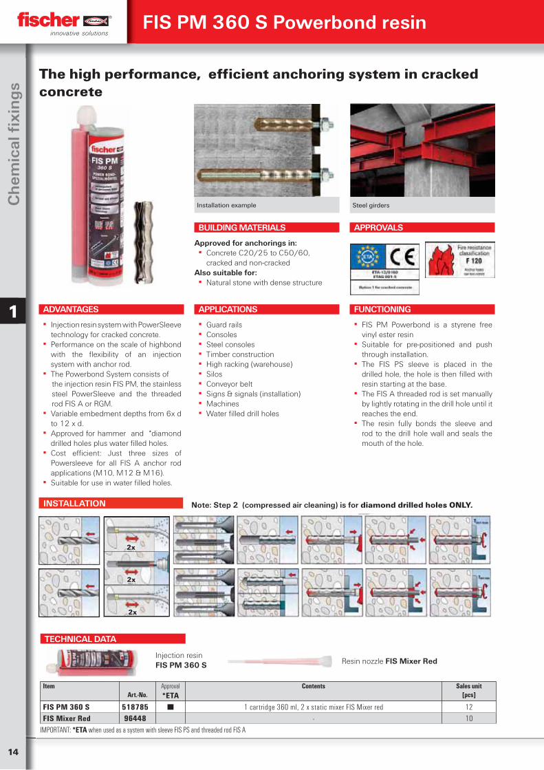
FIS PM 360 S Powerbond resin
The high performance, efficient anchoring system in cracked concrete
APPLICATIONS
▪ Guard rails ▪ Consoles ▪ Steel consoles ▪ Timber construction ▪ High racking (warehouse) ▪ Silos ▪ Conveyor belt ▪ Signs & signals (installation) ▪ Machines ▪ Water filled drill holes
FUNCTIONING
▪ FIS PM Powerbond is a styrene free vinyl ester resin
▪ Suitable for pre-positioned and push through installation.
▪ The FIS PS sleeve is placed in the drilled hole, the hole is then filled with resin starting at the base.
▪ The FIS A threaded rod is set manually by lightly rotating in the drill hole until it reaches the end.
▪ The resin fully bonds the sleeve and rod to the drill hole wall and seals the mouth of the hole.
Installation example Steel girders
BUILDING MATERIALS
Approved for anchorings in: ▪ Concrete C20/25 to C50/60,
cracked and non-crackedAlso suitable for:
▪ Natural stone with dense structure
APPROVALS
ADVANTAGES
▪ Injection resin system with PowerSleeve technology for cracked concrete.
▪ Performance on the scale of highbond with the flexibility of an injection system with anchor rod.
▪ The Powerbond System consists ofthe injection resin FIS PM, the stainless steel PowerSleeve and the threaded rod FIS A or RGM.
▪ Variable embedment depths from 6x d to 12 x d.
▪ Approved for hammer and *diamond drilled holes plus water filled holes.
▪ Cost efficient: Just three sizes of Powersleeve for all FIS A anchor rod applications (M10, M12 & M16).
▪ Suitable for use in water filled holes.
INSTALLATION
TECHNICAL DATA
Item Art.-No.
Approval*ETA
Contents
Sales unit[pcs]
FIS PM 360 S 518785 ■ 1 cartridge 360 ml, 2 x static mixer FIS Mixer red 12FIS Mixer Red 96448 - 10
IMPORTANT: *ETA when used as a system with sleeve FIS PS and threaded rod FIS A
Injection resin FIS PM 360 S Resin nozzle FIS Mixer Red
Note: Step 2 (compressed air cleaning) is for diamond drilled holes ONLY.
2x
2x
2x
15
Ch
emical Fixin
gs
1
FIS PM 360 S Powerbond resin
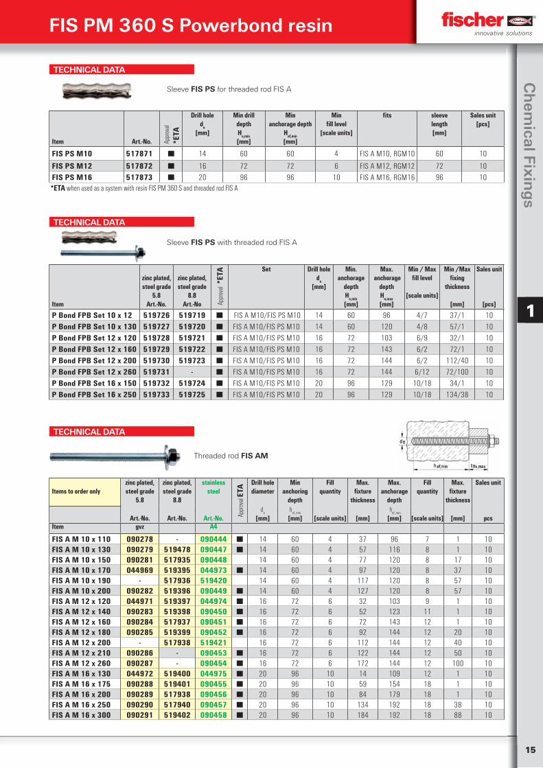
TECHNICAL DATA
Sleeve FIS PS for threaded rod FIS A
Item
Art.-No. Appr
oval
*ETA
Drill holedo
[mm]
Min drilldepthHo,min
[mm]
Min anchorage depth
Hef,min
[mm]
Min fill level
[scale units]
fits sleevelength[mm]
Sales unit[pcs]
FIS PS M10 517871 ■ 14 60 60 4 FIS A M10, RGM10 60 10
FIS PS M12 517872 ■ 16 72 72 6 FIS A M12, RGM12 72 10FIS PS M16 517873 ■ 20 96 96 10 FIS A M16, RGM16 96 10
*ETA when used as a system with resin FIS PM 360 S and threaded rod FIS A
TECHNICAL DATA
Sleeve FIS PS with threaded rod FIS A
Item
zinc plated, steel grade
5.8 Art.-No.
zinc plated, steel grade
8.8 Art.-No Ap
prov
al *
ETA Set Drill hole
do
[mm]
Min. anchorage
depthHo,min
[mm]
Max. anchorage
depthHo,max
[mm]
Min / Max fill level
[scale units]
Min /Max fixing
thickness
[mm]
Sales unit
[pcs]
P Bond FPB Set 10 x 12 519726 519719 ■ FIS A M10/FIS PS M10 14 60 96 4/7 37/1 10P Bond FPB Set 10 x 130 519727 519720 ■ FIS A M10/FIS PS M10 14 60 120 4/8 57/1 10P Bond FPB Set 12 x 120 519728 519721 ■ FIS A M10/FIS PS M10 16 72 103 6/9 32/1 10P Bond FPB Set 12 x 160 519729 519722 ■ FIS A M10/FIS PS M10 16 72 143 6/2 72/1 10P Bond FPB Set 12 x 200 519730 519723 ■ FIS A M10/FIS PS M10 16 72 144 6/2 112/40 10P Bond FPB Set 12 x 260 519731 - ■ FIS A M10/FIS PS M10 16 72 144 6/12 72/100 10P Bond FPB Set 16 x 150 519732 519724 ■ FIS A M10/FIS PS M10 20 96 129 10/18 34/1 10P Bond FPB Set 16 x 250 519733 519725 ■ FIS A M10/FIS PS M10 20 96 129 10/18 134/38 10
TECHNICAL DATA
Items to order onlyzinc plated, steel grade
5.8
zinc plated, steel grade
8.8
stainless steel
Appr
oval
ETA Drill hole
diameter Min
anchoring depth
Fillquantity
Max. fixture
thickness
Max. anchorage
depth
Fillquantity
Max. fixture
thickness
Sales unit
do
hef, min
hef, min
Art.-No. Art.-No. Art.-No. [mm] [mm] [scale units] [mm] [mm] [scale units] [mm] pcsItem gvz A4
FIS A M 10 x 110 090278 - 090444 ■ 14 60 4 37 96 7 1 10FIS A M 10 x 130 090279 519478 090447 ■ 14 60 4 57 116 8 1 10FIS A M 10 x 150 090281 517935 090448 14 60 4 77 120 8 17 10FIS A M 10 x 170 044969 519395 044973 ■ 14 60 4 97 120 8 37 10FIS A M 10 x 190 - 517936 519420 14 60 4 117 120 8 57 10FIS A M 10 x 200 090282 519396 090449 ■ 14 60 4 127 120 8 57 10FIS A M 12 x 120 044971 519397 044974 ■ 16 72 6 32 103 9 1 10FIS A M 12 x 140 090283 519398 090450 ■ 16 72 6 52 123 11 1 10FIS A M 12 x 160 090284 517937 090451 ■ 16 72 6 72 143 12 1 10FIS A M 12 x 180 090285 519399 090452 ■ 16 72 6 92 144 12 20 10FIS A M 12 x 200 - 517938 519421 16 72 6 112 144 12 40 10FIS A M 12 x 210 090286 - 090453 ■ 16 72 6 122 144 12 50 10FIS A M 12 x 260 090287 - 090454 ■ 16 72 6 172 144 12 100 10FIS A M 16 x 130 044972 519400 044975 ■ 20 96 10 14 109 12 1 10FIS A M 16 x 175 090288 519401 090455 ■ 20 96 10 59 154 18 1 10FIS A M 16 x 200 090289 517938 090456 ■ 20 96 10 84 179 18 1 10FIS A M 16 x 250 090290 517940 090457 ■ 20 96 10 134 192 18 38 10FIS A M 16 x 300 090291 519402 090458 ■ 20 96 10 184 192 18 88 10
Threaded rod FIS AM
16
Ch
emic
al fi
xin
gs
1
FIS PM 360 S Powerbond resin
TECHNICAL DATA
Items to order onlyzinc plated,
steel grade 5.8zinc plated,
steel grade 8.8stainless
steel
Appr
oval Drill hole diameter
PowerbondDrill hole diameter
FIS EMMax. useful length
FIS EMSales unit
do
do
tfix, max
Art.-No. Art.-No. Art.-No. ETA [mm] [mm] [mm] [pcs]Item gvz gvz A4
FIS A M 10 x 1000 509215 1) 509223 1) 509231 1) ■ 14 14 60 10FIS A M 12 x 1000 509216 1) 509224 1) 509232 1) ■ 16 14 70 10FIS A M 16 x 1000 509217 1) 509225 1) 509233 1) ■ 20 18 80 101) Order nut and washer separately.
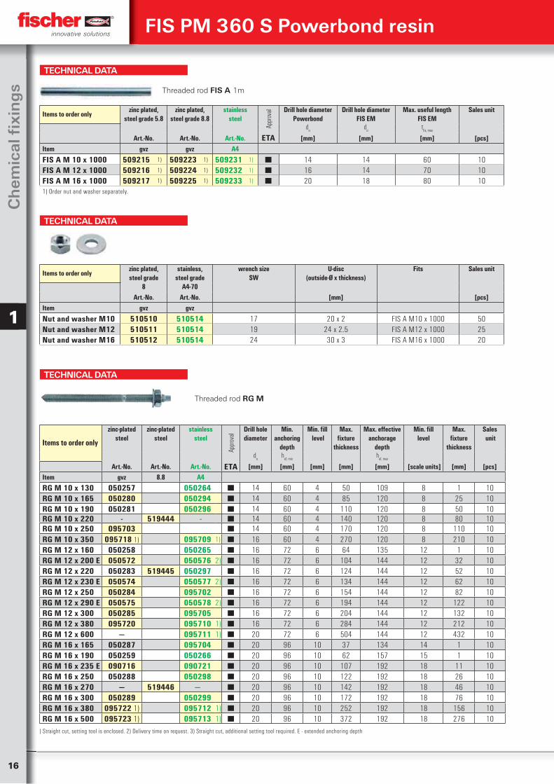
Threaded rod FIS A 1m
TECHNICAL DATA
Items to order onlyzinc plated, steel grade
8
stainless, steel grade
A4-70
wrench sizeSW
U-disc(outside-Ø x thickness)
Fits Sales unit
Art.-No. Art.-No. [mm] [pcs]Item gvz gvz
Nut and washer M10 510510 510514 17 20 x 2 FIS A M10 x 1000 50Nut and washer M12 510511 510514 19 24 x 2.5 FIS A M12 x 1000 25Nut and washer M16 510512 510514 24 30 x 3 FIS A M16 x 1000 20
TECHNICAL DATA
Threaded rod RG M
Items to order only
zinc-plated steel
zinc-plated steel
stainless steel
Appr
oval
Drill hole diameter
Min.anchoring
depth
Min. fill level
Max. fixture
thickness
Max. effective anchorage
depth
Min. filllevel
Max. fixture
thickness
Sales unit
do
hef, min
hef, max
Art.-No. Art.-No. Art.-No. ETA [mm] [mm] [mm] [mm] [mm] [scale units] [mm] [pcs]Item gvz 8.8 A4
RG M 10 x 130 050257 050264 ■ 14 60 4 50 109 8 1 10RG M 10 x 165 050280 050294 ■ 14 60 4 85 120 8 25 10RG M 10 x 190 050281 050296 ■ 14 60 4 110 120 8 50 10RG M 10 x 220 - 519444 - ■ 14 60 4 140 120 8 80 10RG M 10 x 250 095703 ■ 14 60 4 170 120 8 110 10RG M 10 x 350 095718 1) 095709 1) ■ 16 60 4 270 120 8 210 10RG M 12 x 160 050258 050265 ■ 16 72 6 64 135 12 1 10RG M 12 x 200 E 050572 050576 2) ■ 16 72 6 104 144 12 32 10RG M 12 x 220 050283 519445 050297 ■ 16 72 6 124 144 12 52 10RG M 12 x 230 E 050574 050577 2) ■ 16 72 6 134 144 12 62 10RG M 12 x 250 050284 095702 ■ 16 72 6 154 144 12 82 10RG M 12 x 290 E 050575 050578 2) ■ 16 72 6 194 144 12 122 10RG M 12 x 300 050285 095705 ■ 16 72 6 204 144 12 132 10RG M 12 x 380 095720 095710 1) ■ 16 72 6 284 144 12 212 10RG M 12 x 600 — 095711 1) ■ 20 72 6 504 144 12 432 10RG M 16 x 165 050287 095704 ■ 20 96 10 37 134 14 1 10RG M 16 x 190 050259 050266 ■ 20 96 10 62 157 15 1 10RG M 16 x 235 E 090716 090721 ■ 20 96 10 107 192 18 11 10RG M 16 x 250 050288 050298 ■ 20 96 10 122 192 18 26 10RG M 16 x 270 — 519446 — ■ 20 96 10 142 192 18 46 10RG M 16 x 300 050289 050299 ■ 20 96 10 172 192 18 76 10RG M 16 x 380 095722 1) 095712 1) ■ 20 96 10 252 192 18 156 10RG M 16 x 500 095723 1) 095713 1) ■ 20 96 10 372 192 18 276 10
) Straight cut, setting tool is enclosed. 2) Delivery time on request. 3) Straight cut, additional setting tool required. E - extended anchoring depth
17
Ch
emical Fixin
gs
1
FIS PM 360 S Powerbond resin
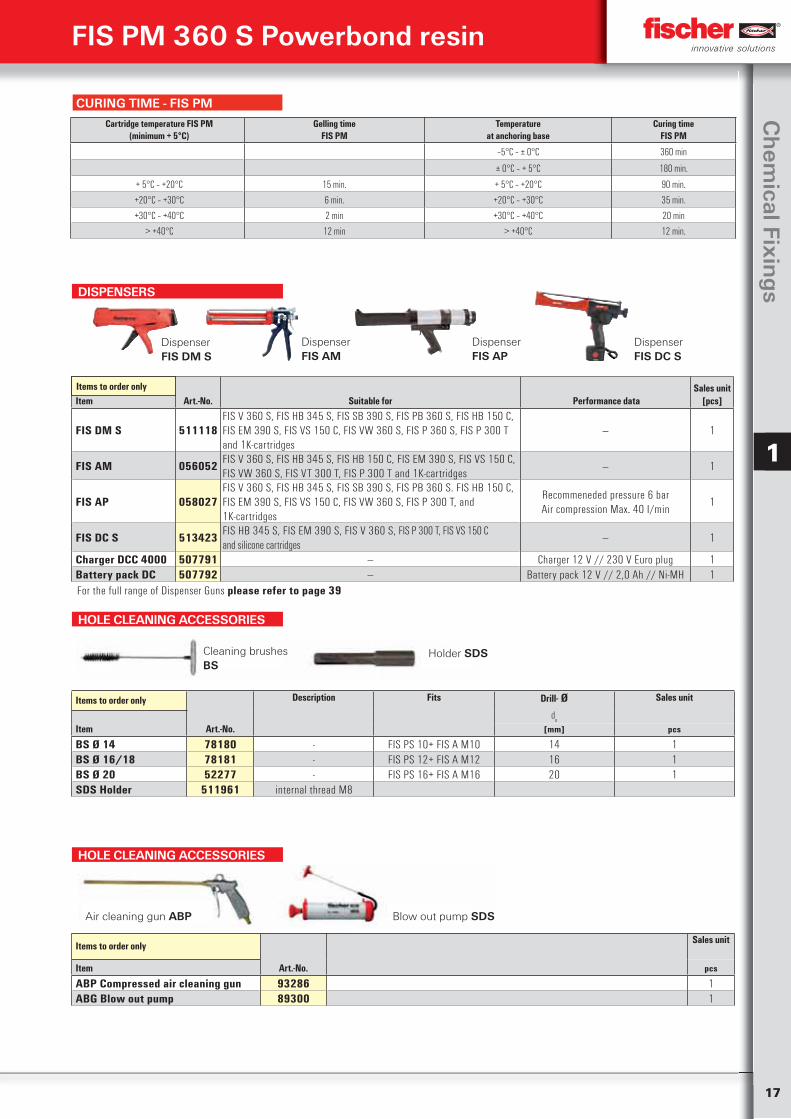
HOLE CLEANING ACCESSORIES
Items to order only Description Fits Drill- Ø Sales unit
do
Item Art.-No. [mm] pcs
BS Ø 14 78180 - FIS PS 10+ FIS A M10 14 1BS Ø 16/18 78181 - FIS PS 12+ FIS A M12 16 1BS Ø 20 52277 - FIS PS 16+ FIS A M16 20 1SDS Holder 511961 internal thread M8
Cleaning brushesBS
Holder SDS
DISPENSERS
Item Art.-No. Suitable for Performance dataSales unit
[pcs]
FIS DM S 511118FIS V 360 S, FIS HB 345 S, FIS SB 390 S, FIS PB 360 S, FIS HB 150 C, FIS EM 390 S, FIS VS 150 C, FIS VW 360 S, FIS P 360 S, FIS P 300 T and 1K-cartridges
— 1
FIS AM 056052FIS V 360 S, FIS HB 345 S, FIS HB 150 C, FIS EM 390 S, FIS VS 150 C, FIS VW 360 S, FIS VT 300 T, FIS P 300 T and 1K-cartridges
— 1
FIS AP 058027FIS V 360 S, FIS HB 345 S, FIS SB 390 S, FIS PB 360 S. FIS HB 150 C, FIS EM 390 S, FIS VS 150 C, FIS VW 360 S, FIS P 300 T, and 1K-cartridges
Recommeneded pressure 6 barAir compression Max. 40 I/min
1
FIS DC S 513423FIS HB 345 S, FIS EM 390 S, FIS V 360 S, FIS P 300 T, FIS VS 150 C and silicone cartridges
— 1
Charger DCC 4000 507791 — Charger 12 V // 230 V Euro plug 1Battery pack DC 507792 — Battery pack 12 V // 2,0 Ah // Ni-MH 1
Items to order only
DispenserFIS AM
Dispenser FIS DM S
Dispenser FIS DC S
Dispenser FIS AP
HOLE CLEANING ACCESSORIES
Items to order onlySales unit
Item Art.-No. pcs
ABP Compressed air cleaning gun 93286 1ABG Blow out pump 89300 1
Air cleaning gun ABP Blow out pump SDS
CURING TIME - FIS PM
Cartridge temperature FIS PM(minimum + 5°C)
Gelling timeFIS PM
Temperatureat anchoring base
Curing timeFIS PM
‒5°C – ± 0°C 360 min
± 0°C – + 5°C 180 min.
+ 5°C – +20°C 15 min. + 5°C – +20°C 90 min.
+20°C – +30°C 6 min. +20°C – +30°C 35 min.
+30°C – +40°C 2 min +30°C – +40°C 20 min
> +40°C 12 min > +40°C 12 min.
For the full range of Dispenser Guns please refer to page 39
18
Ch
emic
al fi
xin
gs
1
FIS PM 360 S Powerbond resin
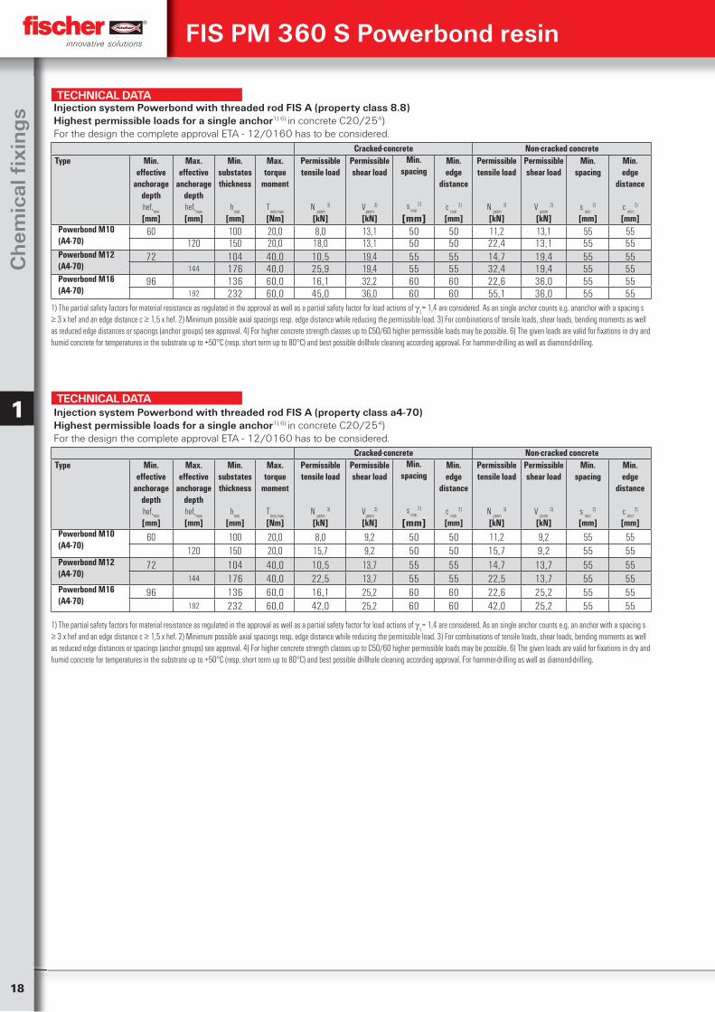
1) The partial safety factors for material resistance as regulated in the approval as well as a partial safety factor for load actions of L= 1,4 are considered. As an single anchor counts e.g. an anchor with a spacing s
≥ 3 x hef and an edge distance c ≥ 1,5 x hef. 2) Minimum possible axial spacings resp. edge distance while reducing the permissible load. 3) For combinations of tensile loads, shear loads, bending moments as well as reduced edge distances or spacings (anchor groups) see approval. 4) For higher concrete strength classes up to C50/60 higher permissible loads may be possible. 6) The given loads are valid for fixations in dry and humid concrete for temperatures in the substrate up to +50°C (resp. short term up to 80°C) and best possible drillhole cleaning according approval. For hammer-drilling as well as diamond-drilling.
TECHNICAL DATA
Cracked-concrete Non-cracked concreteType Min.
effectiveanchorage
depthhef,
min
[mm]
Max.effective
anchoragedepthhef,
max
[mm]
Min.substatesthickness
hmin
[mm]
Max.torque
moment
Tinst,max
[Nm]
Permissibletensile load
N perm
3)
[kN]
Permissibleshear load
Vperm
3)
[kN]
Min.spacing
s min
2)
[mm]
Min.edge
distance
c min
2)
[mm]
Permissibletensile load
N perm
3)
[kN]
Permissibleshear load
V perm
3)
[kN]
Min.spacing
s min
2)
[mm]
Min.edge
distance
c min
2)
[mm]Powerbond M10(A4-70)
60 100 20,0 8,0 9,2 50 50 11,2 9,2 55 55120 150 20,0 15,7 9,2 50 50 15,7 9,2 55 55
Powerbond M12(A4-70)
72 104 40,0 10,5 13,7 55 55 14,7 13,7 55 55144 176 40,0 22,5 13,7 55 55 22,5 13,7 55 55
Powerbond M16(A4-70)
96 136 60,0 16,1 25,2 60 60 22,6 25,2 55 55192 232 60,0 42,0 25,2 60 60 42,0 25,2 55 55
Injection system Powerbond with threaded rod FIS A (property class a4-70)Highest permissible loads for a single anchor1) 6) in concrete C20/254)For the design the complete approval ETA - 12/0160 has to be considered.
TECHNICAL DATA
Cracked-concrete Non-cracked concreteType Min.
effectiveanchorage
depthhef,
min
[mm]
Max.effective
anchoragedepthhef,
max
[mm]
Min.substatesthickness
hmin
[mm]
Max.torque
moment
Tinst,max
[Nm]
Permissibletensile load
N perm
3)
[kN]
Permissibleshear load
Vperm
3)
[kN]
Min.spacing
s min
2)
[mm]
Min.edge
distance
c min
2)
[mm]
Permissibletensile load
N perm
3)
[kN]
Permissibleshear load
V perm
3)
[kN]
Min.spacing
s min
2)
[mm]
Min.edge
distance
c min
2)
[mm]Powerbond M10(A4-70)
60 100 20,0 8,0 13,1 50 50 11,2 13,1 55 55120 150 20,0 18,0 13,1 50 50 22,4 13,1 55 55
Powerbond M12(A4-70)
72 104 40,0 10,5 19,4 55 55 14,7 19,4 55 55144 176 40,0 25,9 19,4 55 55 32,4 19,4 55 55
Powerbond M16(A4-70)
96 136 60,0 16,1 32,2 60 60 22,6 36,0 55 55192 232 60,0 45,0 36,0 60 60 55,1 36,0 55 55
1) The partial safety factors for material resistance as regulated in the approval as well as a partial safety factor for load actions of L= 1,4 are considered. As an single anchor counts e.g. ananchor with a spacing s
≥ 3 x hef and an edge distance c ≥ 1,5 x hef. 2) Minimum possible axial spacings resp. edge distance while reducing the permissible load. 3) For combinations of tensile loads, shear loads, bending moments as well as reduced edge distances or spacings (anchor groups) see approval. 4) For higher concrete strength classes up to C50/60 higher permissible loads may be possible. 6) The given loads are valid for fixations in dry and humid concrete for temperatures in the substrate up to +50°C (resp. short term up to 80°C) and best possible drillhole cleaning according approval. For hammer-drilling as well as diamond-drilling.
Injection system Powerbond with threaded rod FIS A (property class 8.8) Highest permissible loads for a single anchor1) 6) in concrete C20/254) For the design the complete approval ETA - 12/0160 has to be considered.
19
Ch
emical Fixin
gs
1
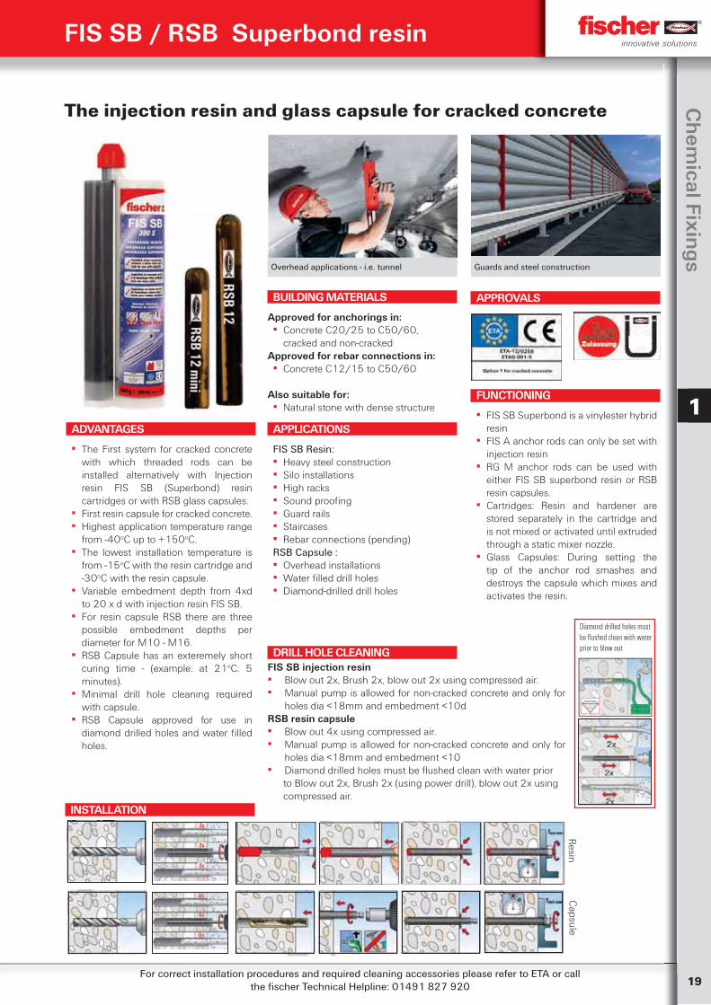
The injection resin and glass capsule for cracked concrete
APPLICATIONS
FIS SB Resin: ▪ Heavy steel construction ▪ Silo installations ▪ High racks ▪ Sound proofing ▪ Guard rails ▪ Staircases ▪ Rebar connections (pending)
RSB Capsule : ▪ Overhead installations ▪ Water filled drill holes ▪ Diamond-drilled drill holes
ADVANTAGES
▪ The First system for cracked concrete with which threaded rods can be installed alternatively with Injection resin FIS SB (Superbond) resin cartridges or with RSB glass capsules.
▪ First resin capsule for cracked concrete. ▪ Highest application temperature range
from -40oC up to +150oC. ▪ The lowest installation temperature is
from -15oC with the resin cartridge and -30oC with the resin capsule.
▪ Variable embedment depth from 4xd to 20 x d with injection resin FIS SB.
▪ For resin capsule RSB there are three possible embedment depths per diameter for M10 - M16.
▪ RSB Capsule has an exteremely short curing time - (example: at 21oC: 5 minutes).
▪ Minimal drill hole cleaning required with capsule.
▪ RSB Capsule approved for use in diamond drilled holes and water filled holes.
FUNCTIONING
▪ FIS SB Superbond is a vinylester hybrid resin
▪ FIS A anchor rods can only be set with injection resin
▪ RG M anchor rods can be used with either FIS SB superbond resin or RSB resin capsules.
▪ Cartridges: Resin and hardener are stored separately in the cartridge and is not mixed or activated until extruded through a static mixer nozzle.
▪ Glass Capsules: During setting the tip of the anchor rod smashes and destroys the capsule which mixes and activates the resin.
Overhead applications - i.e. tunnel Guards and steel construction
BUILDING MATERIALS
Approved for anchorings in: ▪ Concrete C20/25 to C50/60,
cracked and non-crackedApproved for rebar connections in:
▪ Concrete C12/15 to C50/60 Also suitable for:
▪ Natural stone with dense structure
APPROVALS
FIS SB / RSB Superbond resin
FIS SB injection resin ▪ Blow out 2x, Brush 2x, blow out 2x using compressed air. ▪ Manual pump is allowed for non-cracked concrete and only for
holes dia <18mm and embedment <10dRSB resin capsule ▪ Blow out 4x using compressed air. ▪ Manual pump is allowed for non-cracked concrete and only for
holes dia <18mm and embedment <10 ▪ Diamond drilled holes must be flushed clean with water prior to Blow out 2x, Brush 2x (using power drill), blow out 2x using compressed air.
DRILL HOLE CLEANING
For correct installation procedures and required cleaning accessories please refer to ETA or call the fischer Technical Helpline: 01491 827 920
INSTALLATION
Resin
Diamond drilled holes must be flushed clean with water prior to blow out
2x
2x
2x
Capsule
20
Ch
emic
al fi
xin
gs
1
TECHNICAL DATA
Item
Art.-No.
ApprovalETA
Drill hole dia do
[mm]
Drill hole depth ho
[mm]
Anchorage depthhef
[mm]
Suitable for
Sales unit[pcs]
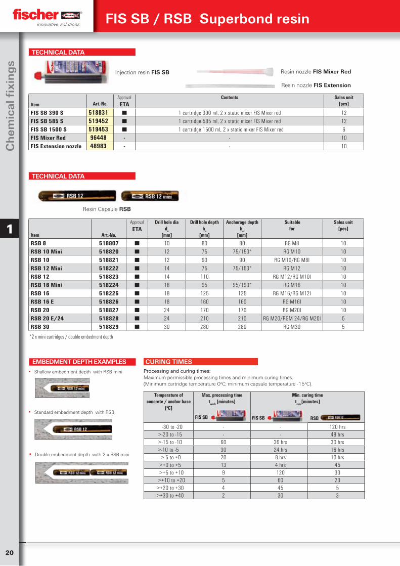
RSB 8 518807 ■ 10 80 80 RG M8 10RSB 10 Mini 518820 ■ 12 75 75/150* RG M10 10RSB 10 518821 ■ 12 90 90 RG M10/RG M8I 10RSB 12 Mini 518222 ■ 14 75 75/150* RG M12 10RSB 12 518823 ■ 14 110 RG M12/RG M10I 10RSB 16 Mini 518224 ■ 18 95 95/190* RG M16 10RSB 16 518225 ■ 18 125 125 RG M16/RG M12I 10RSB 16 E 518826 ■ 18 160 160 RG M16I 10RSB 20 518827 ■ 24 170 170 RG M20I 10RSB 20 E/24 518828 ■ 24 210 210 RG M20/RGM 24/RG M20I 5RSB 30 518829 ■ 30 280 280 RG M30 5
FIS SB / RSB Superbond resin
*2 x mini cartridges / double embedment depth
TECHNICAL DATA
Injection resin FIS SB
Item
Art.-No.ApprovalETA
Contents
Sales unit[pcs]
FIS SB 390 S 518831 ■ 1 cartridge 390 ml, 2 x static mixer FIS Mixer red 12FIS SB 585 S 519452 ■ 1 cartridge 585 ml, 2 x static mixer FIS Mixer red 12FIS SB 1500 S 519453 ■ 1 cartridge 1500 ml, 2 x static mixer FIS Mixer red 6FIS Mixer Red 96448 - - 10FIS Extension nozzle 48983 - - 10
Resin nozzle FIS Mixer Red
Temperature of concrete / anchor base
[oC]
Max. processing timetwork [minutes]
Min. curing timetcure[minutes]
-30 to -20 - - 120 hrs>-20 to -15 - - 48 hrs>-15 to -10 60 36 hrs 30 hrs>-10 to -5 30 24 hrs 16 hrs >-5 to +0 20 8 hrs 10 hrs>+0 to +5 13 4 hrs 45
>+5 to +10 9 120 30 >+10 to +20 5 60 20>+20 to +30 4 45 5>+30 to +40 2 30 3
FIS SB FIS SB RSB
CURING TIMESProcessing and curing times:Maximum permissible processing times and minimum curing times. (Minimum cartridge temperature 0oC; minimum capsule temperature -15oC).
Resin nozzle FIS Extension
▪ Shallow embedment depth with RSB mini
EMBEDMENT DEPTH EXAMPLES
▪ Standard embedment depth with RSB
▪ Double embedment depth with 2 x RSB mini
Resin Capsule RSB
21
Ch
emical Fixin
gs
1
FIS SB / RSB Superbond resin
TECHNICAL DATA
Items to order onlyzinc plated, steel grade
8
stainless, steel grade
A4-70
wrench sizeSW
U-disc(outside-Ø x thickness)
Fits Sales unit
Art.-No. Art.-No. [mm] [pcs]Item gvz gvz
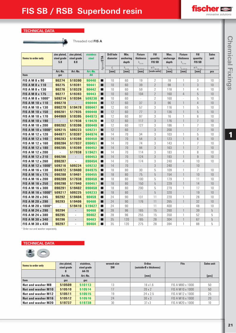
Nut and washer M8 510509 510113 13 16 x1.6 FIS A M80 x 1000 50Nut and washer M10 510510 510514 17 20 x 2 FIS A M10 x 1000 50Nut and washer M12 510511 510515 19 24 x 2.5 FIS A M12 x 1000 25Nut and washer M16 510512 510516 24 30 x 3 FIS A M16 x 1000 20Nut and washer M20 519737 519738 30 37 x 3 FIS A M20 x 1000 10
TECHNICAL DATA
Items to order onlyzinc plated, steel grade
5.8
zinc plated, steel grade
8.8
stainless steel
Appr
oval
ETA
Drill hole diameter
Min. anchoring
depth
Fixture thickness
hef, min
FillquantityFIS SB
Max. anchorage
depth
Fixture thickness
hef, max
FillquantityFIS SB
Sales unit
do
hef, min
tfix, hef min
at h hef, min
hef, max
tfix, hef min
at h hef, min
Art.-No. Art.-No. Art.-No. [mm] [mm] [mm] [scale units] [mm] [mm] [mm] pcsItem gvz A4
FIS A M 8 x 90 90274 519390 90440 ■ 10 60 19 2 78 1 3 10FIS A M 8 x 110 90275 519391 90441 ■ 10 60 39 2 98 1 3 10FIS A M 8 x 130 90276 519329 90442 ■ 10 60 59 2 118 1 4 10FIS A M 8 x 175 90277 519393 90443 ■ 10 60 104 2 160 4 5 10FIS A M 8 x 1000* 509214 519394 509230 ■ 10 60 - 2 160 - 5 10FIS A M 10 x 110 090278 - 090444 ■ 12 60 37 3 96 1 4 10FIS A M 10 x 130 090279 519478 090447 ■ 12 60 57 3 116 1 5 10FIS A M 10 x 150 090281 517935 090448 ■ 12 60 77 3 136 1 5 10FIS A M 10 x 170 044969 519395 044973 ■ 12 60 97 3 16 1 6 10FIS A M 10 x 190 - 517936 519420 ■ 12 60 117 3 176 1 7 10FIS A M 10 x 200 090282 519396 090449 ■ 12 60 127 3 186 1 7 10FIS A M 10 x 1000* 509215 509223 509231 ■ 12 60 - 3 200 - 7 10FIS A M 12 x 120 044971 519397 044974 ■ 14 70 34 3 103 1 5 10FIS A M 12 x 140 090283 519398 090450 ■ 14 70 54 3 123 1 6 10FIS A M 12 x 160 090284 517937 090451 ■ 14 70 74 3 143 1 7 10FIS A M 12 x 180 090285 519399 090452 ■ 14 70 94 3 163 1 7 10FIS A M 12 x 200 - 517938 519421 ■ 14 70 114 3 183 1 8 10FIS A M 12 x 210 090286 - 090453 ■ 14 70 124 3 193 1 9 10FIS A M 12 x 260 090287 - 090454 ■ 14 70 174 3 240 4 10 10FIS A M 12 x 1000* 509216 509224 509232 ■ 14 70 - 3 240 - 10FIS A M 16 x 130 044972 519400 044975 ■ 18 80 30 5 109 1 7 10FIS A M 16 x 175 090288 519401 090455 ■ 18 80 75 5 154 1 10 10FIS A M 16 x 200 090289 517938 090456 ■ 18 80 100 5 179 1 11 10FIS A M 16 x 250 090290 517940 090457 ■ 18 80 150 5 229 1 14 10FIS A M 16 x 300 090291 519402 090458 ■ 18 80 200 5 279 1 17 10FIS A M 16 x 1000* 509217 509225 509233 ■ 18 80 - 5 320 - 19 10FIS A M 20 x 245 90292 519404 90459 ■ 24 90 131 11 220 1 28 10FIS A M 20 x 290 90293 519406 90460 ■ 24 90 176 11 265 1 32 10FIS A M 20 x 1000* - 519410 519427 ■ 24 90 - 11 400 - 48 10FIS A M 24 x 290 90294 - 90468 ■ 28 96 165 15 260 1 39 5FIS A M 24 x 380 90295 - 90462 ■ 28 96 255 15 350 1 52 5FIS A M 30 x 340 90296 - 90463 ■ 35 120 185 28 304 1 67 5FIS A M 30 x 430 90297 - 90464 ■ 35 120 275 28 394 1 88 5
Threaded rod FIS A
* Order nut and washer separately.
22
Ch
emic
al fi
xin
gs
1
FIS SB / RSB Superbond resin
TECHNICAL DATA
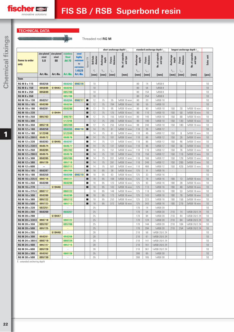
Threaded rod RG M
short anchorage depth hef, 1
standard anchorage depth hef, 2
longest anchorage depth hef, 2
Items to order only
zinc-plated steel5.8
zinc-plated steel88
stainless Steel
A4-70
steel highly
resistant to
corrosion1.4529
Appr
oval
ETA
Drill
hol
e di
amet
er
Anch
orag
e
dept
h
Fixt
ure
thic
knes
s
No. o
f cap
sule
san
d ty
pe
Anch
orag
e
dept
h
Fixt
ure
thic
knes
s
No. o
f cap
sule
san
d ty
pe
Anch
orag
e
dept
h
Fixt
ure
thic
knes
s
No. o
f cap
sule
san
d ty
pe
Sale
s u
nit
do
hef, 1
tfix, 1
hef, 2
tfix, 2
hef, 3
tfix, 3
Art.-No. Art.-No. Art.-No. Art.-No. [mm] [mm] [mm] [mm] [mm] [mm] [mm] [mm] [mm] [mm] [pcs]Item
RG M 8 x 115 050256 050263 096316 10 80 14 1xRSB 8 10RG M 8 x 150 095698 519443 050293 10 80 54 1xRSB 8 10RG M 8 x 250 095699 095700 10 80 154 1xRSB 8 10RG M 8 x 350 - 095708 10 80 254 1xRSB 8 10RG M 10 x 130 050257 050264 096217 ■ 12 75 35 1xRSB 10 mini 90 20 1xRSB 10 10RG M 10 x 165 050280 050294 ■ 12 75 704 1xRSB 10 mini 90 55 1xRSB 10 10RG M 10 x 190 050281 050296 ■ 12 75 95 1xRSB 10 mini 90 80 1xRSB 10 150 20 1xRSB 10 mini 10RG M 10 x 220 - 519444 - ■ 12 75 125 1xRSB 10 mini 90 110 1xRSB 10 150 50 1xRSB 10 mini 10RG M 10 x 250 095703 095701 ■ 12 75 155 1xRSB 10 mini 90 140 1xRSB 10 150 80 1xRSB 10 mini 10RG M 10 x 300 512246 12 75 205 1xRSB 10 mini 90 190 1xRSB 10 150 130 1xRSB 10 mini 10RG M 10 x 350 095718 095709 ■ 12 75 255 1xRSB 10 mini 98 240 1xRSB 10 150 180 1xRSB 10 mini 10RG M 12 x 160 050258 050265 096218 ■ 14 75 61 1xRSB 12 mini 110 26 1xRSB 12 - - - 10RG M 12 x 180 512248 512249 14 75 81 1xRSB 12 mini 110 46 1xRSB 12 150 6 2xRSB 12 mini 10RG M 12 x 200 E 050572 050576 ■ 14 75 101 1xRSB 12 mini 110 66 1xRSB 12 150 26 2xRSB 12 mini 10
RG M 12 x 220 050283 519445 050297 ■ 14 75 121 1xRSB 12 mini 110 86 1xRSB 12 150 46 2xRSB 12 mini 10
RG M 12 x 230 E 050574 050577 ■ 14 75 131 1xRSB 12 mini 110 96 1xRSB 12 150 56 2xRSB 12 mini 10RG M 12 x 250 050284 095702 ■ 14 75 151 1xRSB 12 mini 110 116 1xRSB 12 150 76 2xRSB 12 mini 10RG M 12 x 290 E 050575 050578 ■ 14 75 191 1xRSB 12 mini 110 156 1xRSB 12 150 116 2xRSB 12 mini 10RG M 12 x 300 050285 095705 ■ 14 75 201 1xRSB 12 mini 110 166 1xRSB 12 150 126 2xRSB 12 mini 10RG M 12 x 380 095720 095710 ■ 14 75 281 1xRSB 12 mini 110 246 1xRSB 12 150 206 2xRSB 12 mini 10RG M 12 x 600 — 095711 ■ 14 75 501 1xRSB 12 mini 110 466 1xRSB 12 150 426 2xRSB 12 mini 10RG M 16 x 165 050287 095704 ■ 18 95 38 1xRSB 16 mini 125 8 1xRSB 16 - - 10RG M 16 x 190 050259 050266 096219 ■ 18 95 63 1xRSB 16 mini 125 33 1xRSB 16 - - 10RG M 16 x 235 E 090716 090721 ■ 18 95 108 1xRSB 16 mini 125 78 1xRSB 16 190 13 2xRSB 16 mini 10RG M 16 x 250 050288 050298 ■ 18 95 123 1xRSB 16 mini 125 93 1xRSB 16 190 28 2xRSB 16 mini 10RG M 16 x 270 - 519446 ■ 18 95 143 1xRSB 16 mini 125 113 1xRSB 16 190 48 2xRSB 16 mini 10RG M 16 x 275 E 090717 090722 18 95 148 1xRSB 16 mini 125 118 1xRSB 16 190 53 2xRSB 16 mini 10RG M 16 x 300 050289 050299 ■ 18 95 173 1xRSB 16 mini 125 143 1xRSB 16 190 78 2xRSB 16 mini 10RG M 16 x 380 095722 095712 ■ 18 95 253 1xRSB 16 mini 125 223 1xRSB 16 190 158 2xRSB 16 mini 10RG M 16 x 500 095723 095713 ■ 18 95 372 1xRSB 16 mini 125 343 1xRSB 16 190 278 2xRSB 16 mini 10RG M 20 x 220 502251 - 25 170 14 1xRSB 20 - - 10RG M 20 x 260 050260 050267 25 170 54 1xRSB 20 210 14 1xRSB 20/E 24 10RG M 20 x 290 - 519447 - 25 170 84 1xRSB 20 210 44 1xRSB 20/E 24 10RG M 20 x 330 E 090718 090723 25 170 124 1xRSB 20 210 84 1xRSB 20/E 24 10RG M 20 x 350 095707 095706 25 170 144 1xRSB 20 210 104 1xRSB 20/E 24 10RG M 20 x 500 095725 - 25 170 294 1xRSB 20 210 254 1xRSB 20/E 24 10RG M 24 x 295 - 519448 - 28 210 56 1xRSB 20/E 24 10RG M 24 x 300 050261 050268 28 210 61 1xRSB 20/E 24 10RG M 24 x 380 E 090719 090724 28 210 141 1xRSB 20/E 24 10RG M 24 x 400 095727 095715 28 210 161 1xRSB 20/E 24 10
RG M 24 x 600 095728 - 28 210 361 1xRSB 20/E 24 10RG M 30 x 380 050262 090726 35 280 65 1xRSB 30 10RG M 30 x 500 095730 - 35 280 185 1xRSB 30 10
E - extended anchoring depth
23
Ch
emical Fixin
gs
1
TECHNICAL DATA
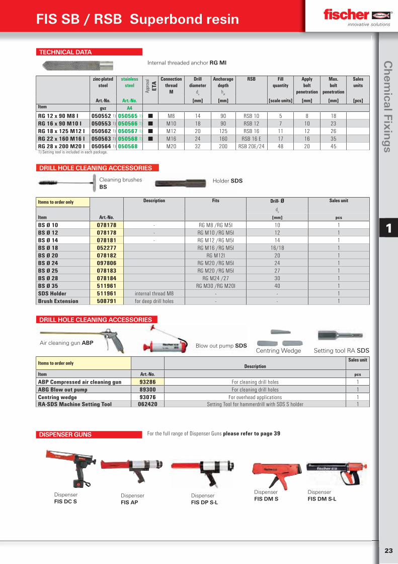
Internal threaded anchor RG MI
zinc-plated steel
stainless steel
Appr
oval
ETA
Connection thread
M
Drill diameter
do
Anchorage depth
hef
RSB Fill quantity
Applybolt
penetration
Max.bolt
penetration
Sales units
Art.-No. Art.-No. [mm] [mm] [scale units] [mm] [mm] [pcs]Item gvz A4
RG 12 x 90 M8 I 050552 1) 050565 1) ■ M8 14 90 RSB 10 5 8 18RG 16 x 90 M10 I 050553 1) 050566 1) ■ M10 18 90 RSB 12 7 10 23RG 18 x 125 M12 I 050562 1) 050567 1) ■ M12 20 125 RSB 16 11 12 26RG 22 x 160 M16 I 050563 1) 050568 1) ■ M16 24 160 RSB 16 E 17 16 35RG 28 x 200 M20 I 050564 1) 050568 M20 32 200 RSB 20E/24 48 20 451) Setting tool is included in each package.
DRILL HOLE CLEANING ACCESSORIES
Items to order onlyDescription
Sales unit
Item Art.-No. pcs
ABP Compressed air cleaning gun 93286 For cleaning drill holes 1ABG Blow out pump 89300 For cleaning drill holes 1Centring wedge 93076 For overhead applications 1RA-SDS Machine Setting Tool 062420 Setting Tool for hammerdrill with SDS S holder 1
Air cleaning gun ABP Blow out pump SDS Centring Wedge Setting tool RA SDS
FIS SB / RSB Superbond resin
DRILL HOLE CLEANING ACCESSORIES
Items to order only Description Fits Drill- Ø Sales unit
do
Item Art.-No. [mm] pcs
BS Ø 10 078178 - RG M8 /RG M5I 10 1BS Ø 12 078178 - RG M10 /RG M5I 12 1BS Ø 14 078181 - RG M12 /RG M5I 14 1BS Ø 18 052277 RG M16 /RG M5I 16/18 1BS Ø 20 078182 RG M12I 20 1BS Ø 24 097806 RG M20 /RG M5I 24 1BS Ø 25 078183 RG M20 /RG M5I 27 1BS Ø 28 078184 RG M24 /27 30 1BS Ø 35 511961 RG M30 /RG M20I 40 1SDS Holder 511961 internal thread M8 - - 1Brush Extension 508791 for deep drill holes - - 1
Cleaning brushesBS
Holder SDS
DISPENSER GUNS
Dispenser FIS DC S
DispenserFIS DP S-L
Dispenser FIS AP
Dispenser FIS DM S-L
Dispenser FIS DM S
For the full range of Dispenser Guns please refer to page 39
24
Ch
emic
al fi
xin
gs
1
FIS SB / RSB Superbond resin
TECHNICAL DATA
Cracked-concrete Non-cracked concreteType Min. Effective
anchoragedepthhef,
min
[mm]
Max. Effectiveanchorage
depthhef,
min
[mm]
Min.substatethickness
hmin
[mm]
Max.torque
moment
Tinst,max
[Nm]
Permissibletensile load
N perm
3)
[kN]
Permissibleshear load
Vperm
3)
[kN]
Min.spacing
s min
2)
[mm]
Min.edge
distance
c min
2)
[mm]
Permissibletensile load
N perm
3)
[kN]
Permissibleshear load
V perm
3)
[kN]
Min.spacing
s min
2)
[mm]
Min.edge
distance
c min
2)
[mm]
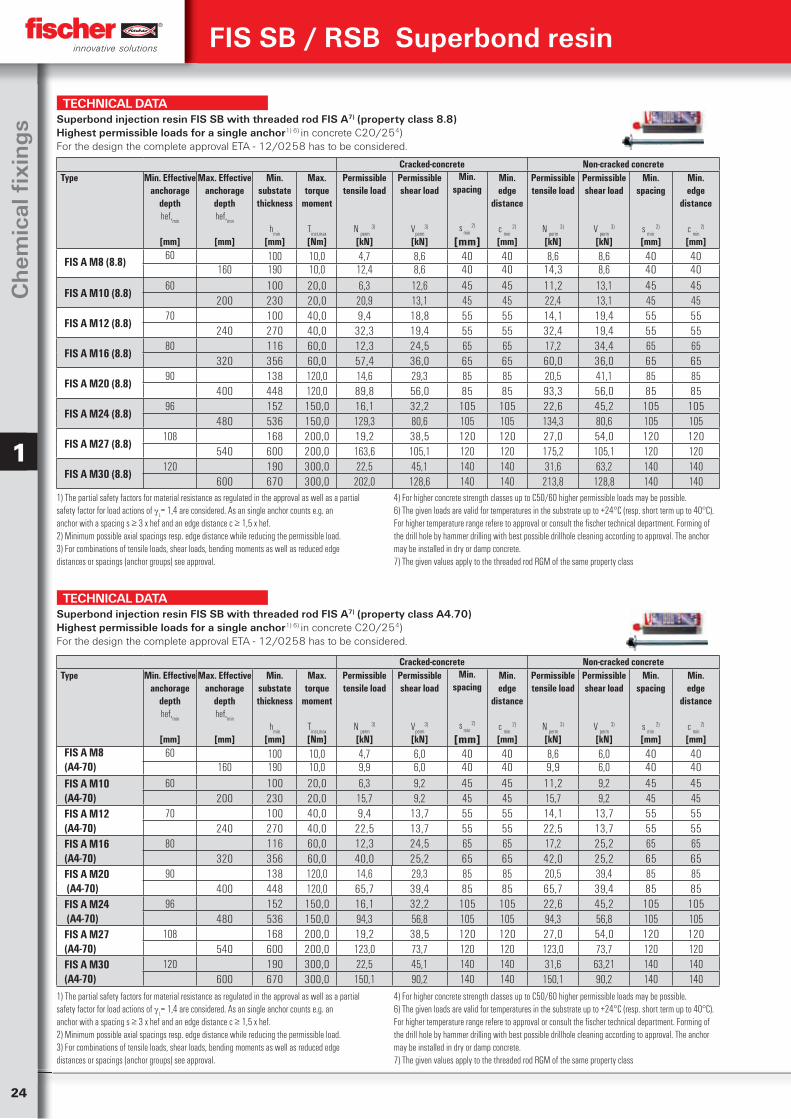
FIS A M8 (8.8) 60 100 10,0 4,7 8,6 40 40 8,6 8,6 40 40160 190 10,0 12,4 8,6 40 40 14,3 8,6 40 40
FIS A M10 (8.8)60 100 20,0 6,3 12,6 45 45 11,2 13,1 45 45
200 230 20,0 20,9 13,1 45 45 22,4 13,1 45 45
FIS A M12 (8.8)70 100 40,0 9,4 18,8 55 55 14,1 19,4 55 55
240 270 40,0 32,3 19,4 55 55 32,4 19,4 55 55
FIS A M16 (8.8)80 116 60,0 12,3 24,5 65 65 17,2 34,4 65 65
320 356 60,0 57,4 36,0 65 65 60,0 36,0 65 65
FIS A M20 (8.8)90 138 120,0 14,6 29,3 85 85 20,5 41,1 85 85
400 448 120,0 89,8 56,0 85 85 93,3 56,0 85 85
FIS A M24 (8.8)96 152 150,0 16,1 32,2 105 105 22,6 45,2 105 105
480 536 150,0 129,3 80,6 105 105 134,3 80,6 105 105
FIS A M27 (8.8)108 168 200,0 19,2 38,5 120 120 27,0 54,0 120 120
540 600 200,0 163,6 105,1 120 120 175,2 105,1 120 120
FIS A M30 (8.8)120 190 300,0 22,5 45,1 140 140 31,6 63,2 140 140
600 670 300,0 202,0 128,6 140 140 213,8 128,8 140 1401) The partial safety factors for material resistance as regulated in the approval as well as a partialsafety factor for load actions of
L= 1,4 are considered. As an single anchor counts e.g. an
anchor with a spacing s ≥ 3 x hef and an edge distance c ≥ 1,5 x hef.2) Minimum possible axial spacings resp. edge distance while reducing the permissible load.3) For combinations of tensile loads, shear loads, bending moments as well as reduced edgedistances or spacings (anchor groups) see approval.
4) For higher concrete strength classes up to C50/60 higher permissible loads may be possible.6) The given loads are valid for temperatures in the substrate up to +24°C (resp. short term up to 40°C). For higher temperature range refere to approval or consult the fischer technical department. Forming of the drill hole by hammer drilling with best possible drillhole cleaning according to approval. The anchor may be installed in dry or damp concrete. 7) The given values apply to the threaded rod RGM of the same property class
Superbond injection resin FIS SB with threaded rod FIS A7) (property class 8.8) Highest permissible loads for a single anchor1) 6) in concrete C20/254)For the design the complete approval ETA - 12/0258 has to be considered.
TECHNICAL DATA
Cracked-concrete Non-cracked concreteType Min. Effective
anchoragedepthhef,
min
[mm]
Max. Effectiveanchorage
depthhef,
min
[mm]
Min.substatethickness
hmin
[mm]
Max.torque
moment
Tinst,max
[Nm]
Permissibletensile load
N perm
3)
[kN]
Permissibleshear load
Vperm
3)
[kN]
Min.spacing
s min
2)
[mm]
Min.edge
distance
c min
2)
[mm]
Permissibletensile load
N perm
3)
[kN]
Permissibleshear load
V perm
3)
[kN]
Min.spacing
s min
2)
[mm]
Min.edge
distance
c min
2)
[mm]FIS A M8 (A4-70)
60 100 10,0 4,7 6,0 40 40 8,6 6,0 40 40160 190 10,0 9,9 6,0 40 40 9,9 6,0 40 40
FIS A M10 (A4-70)
60 100 20,0 6,3 9,2 45 45 11,2 9,2 45 45200 230 20,0 15,7 9,2 45 45 15,7 9,2 45 45
FIS A M12 (A4-70)
70 100 40,0 9,4 13,7 55 55 14,1 13,7 55 55240 270 40,0 22,5 13,7 55 55 22,5 13,7 55 55
FIS A M16 (A4-70)
80 116 60,0 12,3 24,5 65 65 17,2 25,2 65 65320 356 60,0 40,0 25,2 65 65 42,0 25,2 65 65
FIS A M20 (A4-70)
90 138 120,0 14,6 29,3 85 85 20,5 39,4 85 85400 448 120,0 65,7 39,4 85 85 65,7 39,4 85 85
FIS A M24 (A4-70)
96 152 150,0 16,1 32,2 105 105 22,6 45,2 105 105480 536 150,0 94,3 56,8 105 105 94,3 56,8 105 105
FIS A M27 (A4-70)
108 168 200,0 19,2 38,5 120 120 27,0 54,0 120 120540 600 200,0 123,0 73,7 120 120 123,0 73,7 120 120
FIS A M30 (A4-70)
120 190 300,0 22,5 45,1 140 140 31,6 63,21 140 140600 670 300,0 150,1 90,2 140 140 150,1 90,2 140 140
1) The partial safety factors for material resistance as regulated in the approval as well as a partialsafety factor for load actions of
L= 1,4 are considered. As an single anchor counts e.g. an
anchor with a spacing s ≥ 3 x hef and an edge distance c ≥ 1,5 x hef.2) Minimum possible axial spacings resp. edge distance while reducing the permissible load.3) For combinations of tensile loads, shear loads, bending moments as well as reduced edgedistances or spacings (anchor groups) see approval.
4) For higher concrete strength classes up to C50/60 higher permissible loads may be possible.6) The given loads are valid for temperatures in the substrate up to +24°C (resp. short term up to 40°C). For higher temperature range refere to approval or consult the fischer technical department. Forming of the drill hole by hammer drilling with best possible drillhole cleaning according to approval. The anchor may be installed in dry or damp concrete. 7) The given values apply to the threaded rod RGM of the same property class
Superbond injection resin FIS SB with threaded rod FIS A7) (property class A4.70) Highest permissible loads for a single anchor1) 6) in concrete C20/254)For the design the complete approval ETA - 12/0258 has to be considered.
25
Ch
emical Fixin
gs
1
FIS SB / RSB Superbond resin
TECHNICAL DATA
Cracked-concrete Non-cracked concreteType Min. Effective
anchoragedepthhef,
min
[mm]
Max. Effectiveanchorage
depthhef,
min
[mm]
Min.substatethickness
hmin
[mm]
Max.torque
moment
Tinst,max
[Nm]
Permissibletensile load
N perm
3)
[kN]
Permissibleshear load
Vperm
3)
[kN]
Min.spacing
s min
2)
[mm]
Min.edge
distance
c min
2)
[mm]
Permissibletensile load
N perm
3)
[kN]
Permissibleshear load
V perm
3)
[kN]
Min.spacing
s min
2)
[mm]
Min.edge
distance
c min
2)
[mm]
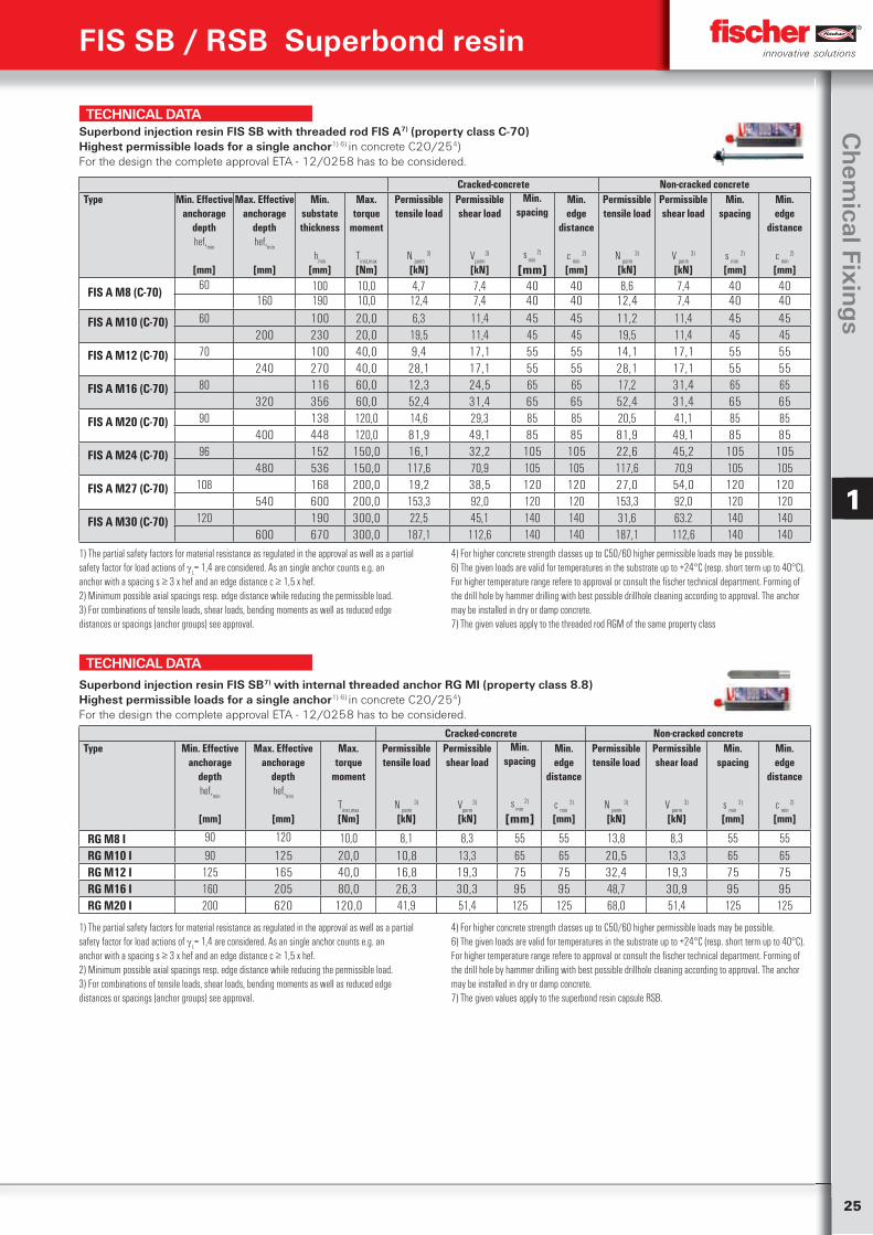
FIS A M8 (C-70) 60 100 10,0 4,7 7,4 40 40 8,6 7,4 40 40160 190 10,0 12,4 7,4 40 40 12,4 7,4 40 40
FIS A M10 (C-70) 60 100 20,0 6,3 11,4 45 45 11,2 11,4 45 45200 230 20,0 19,5 11,4 45 45 19,5 11,4 45 45
FIS A M12 (C-70) 70 100 40,0 9,4 17,1 55 55 14,1 17,1 55 55240 270 40,0 28,1 17,1 55 55 28,1 17,1 55 55
FIS A M16 (C-70) 80 116 60,0 12,3 24,5 65 65 17,2 31,4 65 65320 356 60,0 52,4 31,4 65 65 52,4 31,4 65 65
FIS A M20 (C-70) 90 138 120,0 14,6 29,3 85 85 20,5 41,1 85 85400 448 120,0 81,9 49,1 85 85 81,9 49,1 85 85
FIS A M24 (C-70)
96 152 150,0 16,1 32,2 105 105 22,6 45,2 105 105480 536 150,0 117,6 70,9 105 105 117,6 70,9 105 105
FIS A M27 (C-70) 108 168 200,0 19,2 38,5 120 120 27,0 54,0 120 120540 600 200,0 153,3 92,0 120 120 153,3 92,0 120 120
FIS A M30 (C-70) 120 190 300,0 22,5 45,1 140 140 31,6 63.2 140 140600 670 300,0 187,1 112,6 140 140 187,1 112,6 140 140
1) The partial safety factors for material resistance as regulated in the approval as well as a partialsafety factor for load actions of
L= 1,4 are considered. As an single anchor counts e.g. an
anchor with a spacing s ≥ 3 x hef and an edge distance c ≥ 1,5 x hef.2) Minimum possible axial spacings resp. edge distance while reducing the permissible load.3) For combinations of tensile loads, shear loads, bending moments as well as reduced edgedistances or spacings (anchor groups) see approval.
4) For higher concrete strength classes up to C50/60 higher permissible loads may be possible.6) The given loads are valid for temperatures in the substrate up to +24°C (resp. short term up to 40°C). For higher temperature range refere to approval or consult the fischer technical department. Forming of the drill hole by hammer drilling with best possible drillhole cleaning according to approval. The anchor may be installed in dry or damp concrete. 7) The given values apply to the threaded rod RGM of the same property class
Superbond injection resin FIS SB with threaded rod FIS A7) (property class C-70) Highest permissible loads for a single anchor1) 6) in concrete C20/254)For the design the complete approval ETA - 12/0258 has to be considered.
TECHNICAL DATA
Cracked-concrete Non-cracked concreteType Min. Effective
anchoragedepthhef,
min
[mm]
Max. Effectiveanchorage
depthhef,
min
[mm]
Max.torque
moment
Tinst,max
[Nm]
Permissibletensile load
N perm
3)
[kN]
Permissibleshear load
Vperm
3)
[kN]
Min.spacing
s min
2)
[mm]
Min.edge
distance
c min
2)
[mm]
Permissibletensile load
N perm
3)
[kN]
Permissibleshear load
V perm
3)
[kN]
Min.spacing
s min
2)
[mm]
Min.edge
distance
c min
2)
[mm]
RG M8 I 90 120 10,0 8,1 8,3 55 55 13,8 8,3 55 55RG M10 I 90 125 20,0 10,8 13,3 65 65 20,5 13,3 65 65RG M12 I 125 165 40,0 16,8 19,3 75 75 32,4 19,3 75 75RG M16 I 160 205 80,0 26,3 30,3 95 95 48,7 30,9 95 95RG M20 I 200 620 120,0 41,9 51,4 125 125 68,0 51,4 125 125
1) The partial safety factors for material resistance as regulated in the approval as well as a partialsafety factor for load actions of
L= 1,4 are considered. As an single anchor counts e.g. an
anchor with a spacing s ≥ 3 x hef and an edge distance c ≥ 1,5 x hef.2) Minimum possible axial spacings resp. edge distance while reducing the permissible load.3) For combinations of tensile loads, shear loads, bending moments as well as reduced edgedistances or spacings (anchor groups) see approval.
4) For higher concrete strength classes up to C50/60 higher permissible loads may be possible.6) The given loads are valid for temperatures in the substrate up to +24°C (resp. short term up to 40°C). For higher temperature range refere to approval or consult the fischer technical department. Forming of the drill hole by hammer drilling with best possible drillhole cleaning according to approval. The anchor may be installed in dry or damp concrete. 7) The given values apply to the superbond resin capsule RSB.
Superbond injection resin FIS SB7) with internal threaded anchor RG MI (property class 8.8) Highest permissible loads for a single anchor1) 6) in concrete C20/254)For the design the complete approval ETA - 12/0258 has to be considered.
26
Ch
emic
al fi
xin
gs
1
FIS SB / RSB Superbond resin
TECHNICAL DATA
Cracked-concrete Non-cracked concreteType Min. Effective
anchoragedepthhef,
min
[mm]
Max. Effectiveanchorage
depthhef,
min
[mm]
Max.torque
momentT
inst,max
[Nm]
Permissibletensile load
N perm
3)
[kN]
Permissibleshear load
Vperm
3)
[kN]
Min.spacing
s min
2)
[mm]
Min.edge
distancec
min 2)
[mm]
Permissibletensile load
N perm
3)
[kN]
Permissibleshear load
V perm
3)
[kN]
Min.spacing
s min
2)
[mm]
Min.edge
distancec
min 2)
[mm]
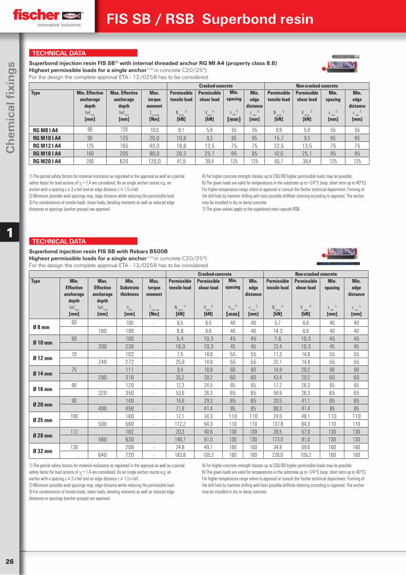
RG M8 I A4 90 120 10,0 8,1 5,9 55 55 9,9 5,9 55 55RG M10 I A4 90 125 20,0 10,8 9,3 65 65 15,7 9,3 65 65RG M12 I A4 125 165 40,0 16,8 13,5 75 75 22,5 13,5 75 75RG M16 I A4 160 205 80,0 26,3 25,1 95 95 42,0 25,1 95 95RG M20 I A4 200 620 120,0 41,9 39,4 125 125 65,7 39,4 125 125
1) The partial safety factors for material resistance as regulated in the approval as well as a partialsafety factor for load actions of
L= 1,4 are considered. As an single anchor counts e.g. an
anchor with a spacing s ≥ 3 x hef and an edge distance c ≥ 1,5 x hef.2) Minimum possible axial spacings resp. edge distance while reducing the permissible load.3) For combinations of tensile loads, shear loads, bending moments as well as reduced edgedistances or spacings (anchor groups) see approval.
4) For higher concrete strength classes up to C50/60 higher permissible loads may be possible.6) The given loads are valid for temperatures in the substrate up to +24°C (resp. short term up to 40°C). For higher temperature range refere to approval or consult the fischer technical department. Forming of the drill hole by hammer drilling with best possible drillhole cleaning according to approval. The anchor may be installed in dry or damp concrete. 7) The given values apply to the superbond resin capsule RSB.
Superbond injection resin FIS SB7) with internal threaded anchor RG MI A4 (property class 8.8) Highest permissible loads for a single anchor1) 6) in concrete C20/254)For the design the complete approval ETA - 12/0258 has to be considered.
TECHNICAL DATA
Cracked-concrete Non-cracked concreteType Min.
Effectiveanchorage
depthhef,
min
[mm]
Max. Effective
anchoragedepthhef,
min
[mm]
Min.Substratethickness
hmin
[mm]
Max.torque
moment
Tinst,max
[Nm]
Permissibletensile load
N perm
3)
[kN]
Permissibleshear load
Vperm
3)
[kN]
Min.spacing
s min
2)
[mm]
Min.edge
distance
c min
2)
[mm]
Permissibletensile load
N perm
3)
[kN]
Permissibleshear load
V perm
3)
[kN]
Min.spacing
s min
2)
[mm]
Min.edge
distance
c min
2)
[mm]
Ø 8 mm60 100 - 6,5 6.5 40 40 5.7 6.6 40 40
160 190 - 8,6 6.6 40 40 14.3 6.6 40 40
Ø 10 mm60 100 - 5,4 10.3 45 45 7.6 10.3 45 45
200 230 - 18,0 10.3 45 45 22.4 10.3 45 45
Ø 12 mm70 102 - 7,5 14.8 55 55 11.3 14.8 55 55
240 272 - 25,9 14.8 55 55 32.1 14.8 55 55
Ø 14 mm75 111 - 9,4 18.8 60 60 14.9 20.2 60 60
280 316 - 35,2 20.2 60 60 43.4 20.2 60 60
Ø 16 mm80 120 - 12,3 24.5 65 65 17.2 26.3 65 65
320 350 - 53,6 26.3 65 65 56.6 26.3 65 65
Ø 20 mm90 140 - 14,6 29.3 85 85 20.5 41.1 85 85
400 450 - 71,8 41.4 85 85 88.3 41.4 85 85
Ø 25 mm100 160 - 17,1 34.3 110 110 24.0 48.1 110 110
500 560 - 112,2 64.3 110 110 137.8 64.3 110 110
Ø 28 mm112 182 - 20,3 40.6 130 130 28.5 57.0 130 130
560 630 - 140,7 81.0 130 130 173.0 81.0 130 130
Ø 32 mm128 208 - 24,8 49.7 160 160 34.8 69.6 160 160
640 720 - 183,8 105.2 160 160 226.0 105.2 160 160
1) The partial safety factors for material resistance as regulated in the approval as well as a partialsafety factor for load actions of
L= 1,4 are considered. As an single anchor counts e.g. an
anchor with a spacing s ≥ 3 x hef and an edge distance c ≥ 1,5 x hef.2) Minimum possible axial spacings resp. edge distance while reducing the permissible load.3) For combinations of tensile loads, shear loads, bending moments as well as reduced edgedistances or spacings (anchor groups) see approval.
4) For higher concrete strength classes up to C50/60 higher permissible loads may be possible.6) The given loads are valid for temperatures in the substrate up to +24°C (resp. short term up to 40°C). For higher temperature range refere to approval or consult the fischer technical department. Forming of the drill hole by hammer drilling with best possible drillhole cleaning according to approval. The anchor may be installed in dry or damp concrete.
Superbond injection resin FIS SB with Rebars B500B Highest permissible loads for a single anchor1) 6) in concrete C20/254)For the design the complete approval ETA - 12/0258 has to be considered.
27
Ch
emical Fixin
gs
1
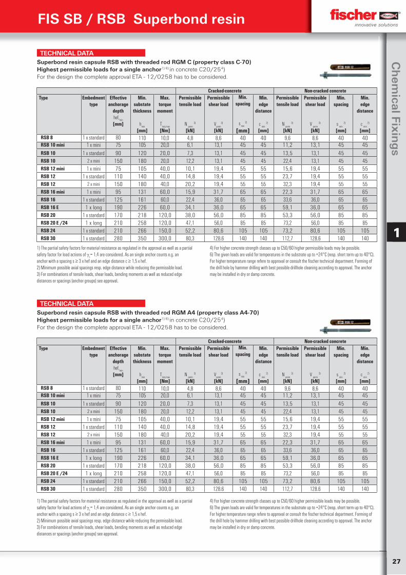
TECHNICAL DATASuperbond resin capsule RSB with threaded rod RGM C (property class C-70) Highest permissible loads for a single anchor1) 6) in concrete C20/254)For the design the complete approval ETA - 12/0258 has to be considered.
Cracked-concrete Non-cracked concreteType Embedment
typeEffective
anchoragedepthhef,
min
[mm]
Min.substatethickness
hmin
[mm]
Max.torque
moment
Tinst,max
[Nm]
Permissibletensile load
N perm
3)
[kN]
Permissibleshear load
Vperm
3)
[kN]
Min.spacing
s min
2)
[mm]
Min.edge
distance
c min
2)
[mm]
Permissibletensile load
N perm
3)
[kN]
Permissibleshear load
V perm
3)
[kN]
Min.spacing
s min
2)
[mm]
Min.edge
distance
c min
2)
[mm]RSB 8 1 x standard 80 110 10,0 4,8 8,6 40 40 9,6 8,6 40 40RSB 10 mini 1 x mini 75 105 20,0 6,1 13,1 45 45 11,2 13,1 45 45RSB 10 1 x standard 90 120 20,0 7,3 13,1 45 45 13,5 13,1 45 45RSB 10 2 x mini 150 180 20,0 12,2 13,1 45 45 22,4 13,1 45 45RSB 12 mini 1 x mini 75 105 40,0 10,1 19,4 55 55 15,6 19,4 55 55RSB 12 1 x standard 110 140 40,0 14,8 19,4 55 55 23,7 19,4 55 55RSB 12 2 x mini 150 180 40,0 20,2 19,4 55 55 32,3 19,4 55 55RSB 16 mini 1 x mini 95 131 60,0 15,9 31,7 65 65 22,3 31,7 65 65RSB 16 1 x standard 125 161 60,0 22,4 36,0 65 65 33,6 36,0 65 65RSB 16 E 1 x long 190 226 60,0 34,1 36,0 65 65 59,1 36,0 65 65RSB 20 1 x standard 170 218 120,0 38,0 56,0 85 85 53,3 56,0 85 85RSB 20 E /24 1 x long 210 258 120,0 47,1 56,0 85 85 73,2 56,0 85 85RSB 24 1 x standard 210 266 150,0 52,2 80,6 105 105 73,2 80,6 105 105RSB 30 1 x standard 280 350 300,0 80,3 128.6 140 140 112,7 128.6 140 140
1) The partial safety factors for material resistance as regulated in the approval as well as a partialsafety factor for load actions of
L= 1,4 are considered. As an single anchor counts e.g. an
anchor with a spacing s ≥ 3 x hef and an edge distance c ≥ 1,5 x hef.2) Minimum possible axial spacings resp. edge distance while reducing the permissible load.3) For combinations of tensile loads, shear loads, bending moments as well as reduced edgedistances or spacings (anchor groups) see approval.
4) For higher concrete strength classes up to C50/60 higher permissible loads may be possible.6) The given loads are valid for temperatures in the substrate up to +24°C (resp. short term up to 40°C). For higher temperature range refere to approval or consult the fischer technical department. Forming of the drill hole by hammer drilling with best possible drillhole cleaning according to approval. The anchor may be installed in dry or damp concrete.
TECHNICAL DATASuperbond resin capsule RSB with threaded rod RGM A4 (property class A4-70) Highest permissible loads for a single anchor1) 6) in concrete C20/254)For the design the complete approval ETA - 12/0258 has to be considered.
Cracked-concrete Non-cracked concreteType Embedment
typeEffective
anchoragedepthhef,
min
[mm]
Min.substatethickness
hmin
[mm]
Max.torque
moment
Tinst,max
[Nm]
Permissibletensile load
N perm
3)
[kN]
Permissibleshear load
Vperm
3)
[kN]
Min.spacing
s min
2)
[mm]
Min.edge
distance
c min
2)
[mm]
Permissibletensile load
N perm
3)
[kN]
Permissibleshear load
V perm
3)
[kN]
Min.spacing
s min
2)
[mm]
Min.edge
distance
c min
2)
[mm]RSB 8 1 x standard 80 110 10,0 4,8 8,6 40 40 9,6 8,6 40 40RSB 10 mini 1 x mini 75 105 20,0 6,1 13,1 45 45 11,2 13,1 45 45RSB 10 1 x standard 90 120 20,0 7,3 13,1 45 45 13,5 13,1 45 45RSB 10 2 x mini 150 180 20,0 12,2 13,1 45 45 22,4 13,1 45 45RSB 12 mini 1 x mini 75 105 40,0 10,1 19,4 55 55 15,6 19,4 55 55RSB 12 1 x standard 110 140 40,0 14,8 19,4 55 55 23,7 19,4 55 55RSB 12 2 x mini 150 180 40,0 20,2 19,4 55 55 32,3 19,4 55 55RSB 16 mini 1 x mini 95 131 60,0 15,9 31,7 65 65 22,3 31,7 65 65RSB 16 1 x standard 125 161 60,0 22,4 36,0 65 65 33,6 36,0 65 65RSB 16 E 1 x long 190 226 60,0 34,1 36,0 65 65 59,1 36,0 65 65RSB 20 1 x standard 170 218 120,0 38,0 56,0 85 85 53,3 56,0 85 85RSB 20 E /24 1 x long 210 258 120,0 47,1 56,0 85 85 73,2 56,0 85 85RSB 24 1 x standard 210 266 150,0 52,2 80,6 105 105 73,2 80,6 105 105RSB 30 1 x standard 280 350 300,0 80,3 128.6 140 140 112,7 128.6 140 140
1) The partial safety factors for material resistance as regulated in the approval as well as a partialsafety factor for load actions of
L= 1,4 are considered. As an single anchor counts e.g. an
anchor with a spacing s ≥ 3 x hef and an edge distance c ≥ 1,5 x hef.2) Minimum possible axial spacings resp. edge distance while reducing the permissible load.3) For combinations of tensile loads, shear loads, bending moments as well as reduced edgedistances or spacings (anchor groups) see approval.
4) For higher concrete strength classes up to C50/60 higher permissible loads may be possible.6) The given loads are valid for temperatures in the substrate up to +24°C (resp. short term up to 40°C). For higher temperature range refere to approval or consult the fischer technical department. Forming of the drill hole by hammer drilling with best possible drillhole cleaning according to approval. The anchor may be installed in dry or damp concrete.
FIS SB / RSB Superbond resin
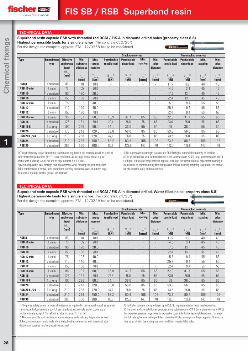
28
Ch
emic
al fi
xin
gs
1
FIS SB / RSB Superbond resin
TECHNICAL DATASuperbond resin capsule RSB with threaded rod RGM / FIS A in diamond drilled holes (property class 8.8) Highest permissible loads for a single anchor1) 6) in concrete C20/254)For the design the complete approval ETA - 12/0258 has to be considered.
Cracked-concrete Non-cracked concreteType Embedment
typeEffective
anchoragedepthhef,
min
[mm]
Min.substatethickness
hmin
[mm]
Max.torque
moment
Tinst,max
[Nm]
Permissibletensile load
N perm
3)
[kN]
Permissibleshear load
Vperm
3)
[kN]
Min.spacing
s min
2)
[mm]
Min.edge
distance
c min
2)
[mm]
Permissibletensile load
N perm
3)
[kN]
Permissibleshear load
V perm
3)
[kN]
Min.spacing
s min
2)
[mm]
Min.edge
distance
c min
2)
[mm]RSB 8 1 x standard 80 110 10,0 - - - - 11,5 8,6 40 40RSB 10 mini 1 x mini 75 105 20,0 - - - - 14,6 13,1 45 45RSB 10 1 x standard 90 120 20,0 - - - - 17,5 13,1 45 45RSB 10 2 x mini 150 180 20,0 - - - - 22,4 13,1 45 45RSB 12 mini 1 x mini 75 105 40,0 - - - - 15,6 19,4 55 55RSB 12 1 x standard 110 140 40,0 - - - - 25,7 19,4 55 55RSB 12 2 x mini 150 180 40,0 - - - - 32,4 19,4 55 55RSB 16 mini 1 x mini 95 131 60,0 15,9 31,7 65 65 22,3 31,7 65 65RSB 16 1 x standard 125 161 60,0 22,4 36,0 65 65 33,6 36,0 65 65RSB 16 E 1 x long 190 226 60,0 34,1 36,0 65 65 60 36,0 65 65RSB 20 1 x standard 170 218 120,0 38,0 56,0 85 85 53,3 56,0 85 85RSB 20 E /24 1 x long 210 258 120,0 47,1 56,0 85 85 73,2 56,0 85 85RSB 24 1 x standard 210 266 150,0 52,2 80,6 105 105 73,2 80,6 105 105RSB 30 1 x standard 280 350 300,0 80,3 128.6 140 140 112,7 128.6 140 140
1) The partial safety factors for material resistance as regulated in the approval as well as a partialsafety factor for load actions of
L= 1,4 are considered. As an single anchor counts e.g. an
anchor with a spacing s ≥ 3 x hef and an edge distance c ≥ 1,5 x hef.2) Minimum possible axial spacings resp. edge distance while reducing the permissible load.3) For combinations of tensile loads, shear loads, bending moments as well as reduced edgedistances or spacings (anchor groups) see approval.
4) For higher concrete strength classes up to C50/60 higher permissible loads may be possible.6)The given loads are valid for temperatures in the substrate up to +24°C (resp. short term up to 40°C). For higher temperature range refere to approval or consult the fischer technical department. Forming of the drill hole by hammer drilling with best possible drillhole cleaning according to approval. The anchor may be installed in dry or damp concrete.
TECHNICAL DATASuperbond resin capsule RSB with threaded rod RGM / FIS A in diamond drilled, Water filled holes (property class 8.8) Highest permissible loads for a single anchor1) 6) in concrete C20/254)For the design the complete approval ETA - 12/0259 has to be considered.
Cracked-concrete Non-cracked concreteType Embedment
typeEffective
anchoragedepthhef,
min
[mm]
Min.substatethickness
hmin
[mm]
Max.torque
moment
Tinst,max
[Nm]
Permissibletensile load
N perm
3)
[kN]
Permissibleshear load
Vperm
3)
[kN]
Min.spacing
s min
2)
[mm]
Min.edge
distance
c min
2)
[mm]
Permissibletensile load
N perm
3)
[kN]
Permissibleshear load
V perm
3)
[kN]
Min.spacing
s min
2)
[mm]
Min.edge
distance
c min
2)
[mm]RSB 8 1 x standard 80 110 10,0 - - - - 11,5 8,6 40 40RSB 10 mini 1 x mini 75 105 20,0 - - - - 14,6 13,1 45 45RSB 10 1 x standard 90 120 20,0 - - - - 17,5 13,1 45 45RSB 10 2 x mini 150 180 20,0 - - - - 22,4 13,1 45 45RSB 12 mini 1 x mini 75 105 40,0 - - - - 15,6 19,4 55 55RSB 12 1 x standard 110 140 40,0 - - - - 25,7 19,4 55 55RSB 12 2 x mini 150 180 40,0 - - - - 32,4 19,4 55 55RSB 16 mini 1 x mini 95 131 60,0 15,9 31,7 65 65 22,3 31,7 65 65RSB 16 1 x standard 125 161 60,0 22,4 36,0 65 65 33,6 36,0 65 65RSB 16 E 1 x long 190 226 60,0 34,1 36,0 65 65 60 36,0 65 65RSB 20 1 x standard 170 218 120,0 38,0 56,0 85 85 53,3 56,0 85 85RSB 20 E /24 1 x long 210 258 120,0 47,1 56,0 85 85 73,2 56,0 85 85RSB 24 1 x standard 210 266 150,0 52,2 80,6 105 105 73,2 80,6 105 105RSB 30 1 x standard 280 350 300,0 80,3 128.6 140 140 112,7 128.6 140 140
1) The partial safety factors for material resistance as regulated in the approval as well as a partialsafety factor for load actions of
L= 1,4 are considered. As an single anchor counts e.g. an
anchor with a spacing s ≥ 3 x hef and an edge distance c ≥ 1,5 x hef.2) Minimum possible axial spacings resp. edge distance while reducing the permissible load.3) For combinations of tensile loads, shear loads, bending moments as well as reduced edgedistances or spacings (anchor groups) see approval.
4) For higher concrete strength classes up to C50/60 higher permissible loads may be possible.6) The given loads are valid for temperatures in the substrate up to +24°C (resp. short term up to 40°C). For higher temperature range refere to approval or consult the fischer technical department. Forming of the drill hole by hammer drilling with best possible drillhole cleaning according to approval. The anchor may be installed in dry or damp concrete in addition to water filled holes.
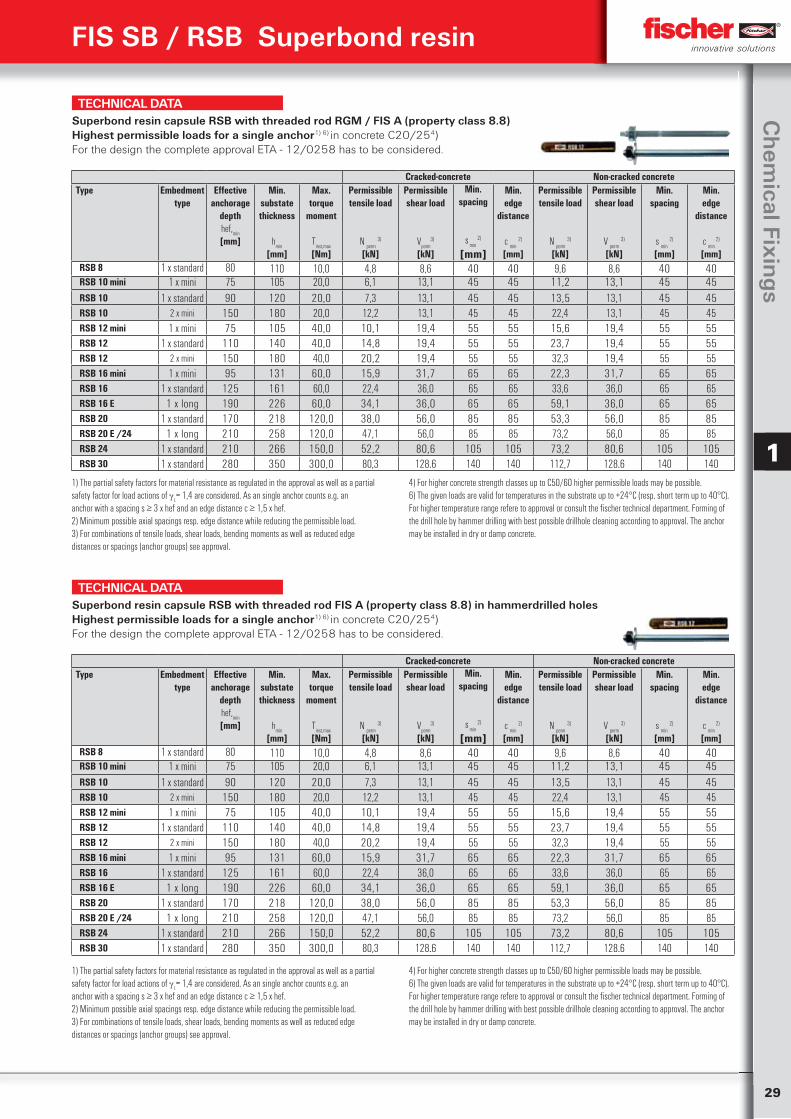
29
Ch
emical Fixin
gs
1
FIS SB / RSB Superbond resin
TECHNICAL DATASuperbond resin capsule RSB with threaded rod RGM / FIS A (property class 8.8) Highest permissible loads for a single anchor1) 6) in concrete C20/254)For the design the complete approval ETA - 12/0258 has to be considered.
Cracked-concrete Non-cracked concreteType Embedment
typeEffective
anchoragedepthhef,
min
[mm]
Min.substatethickness
hmin
[mm]
Max.torque
moment
Tinst,max
[Nm]
Permissibletensile load
N perm
3)
[kN]
Permissibleshear load
Vperm
3)
[kN]
Min.spacing
s min
2)
[mm]
Min.edge
distance
c min
2)
[mm]
Permissibletensile load
N perm
3)
[kN]
Permissibleshear load
V perm
3)
[kN]
Min.spacing
s min
2)
[mm]
Min.edge
distance
c min
2)
[mm]RSB 8 1 x standard 80 110 10,0 4,8 8,6 40 40 9,6 8,6 40 40RSB 10 mini 1 x mini 75 105 20,0 6,1 13,1 45 45 11,2 13,1 45 45RSB 10 1 x standard 90 120 20,0 7,3 13,1 45 45 13,5 13,1 45 45RSB 10 2 x mini 150 180 20,0 12,2 13,1 45 45 22,4 13,1 45 45RSB 12 mini 1 x mini 75 105 40,0 10,1 19,4 55 55 15,6 19,4 55 55RSB 12 1 x standard 110 140 40,0 14,8 19,4 55 55 23,7 19,4 55 55RSB 12 2 x mini 150 180 40,0 20,2 19,4 55 55 32,3 19,4 55 55RSB 16 mini 1 x mini 95 131 60,0 15,9 31,7 65 65 22,3 31,7 65 65RSB 16 1 x standard 125 161 60,0 22,4 36,0 65 65 33,6 36,0 65 65RSB 16 E 1 x long 190 226 60,0 34,1 36,0 65 65 59,1 36,0 65 65RSB 20 1 x standard 170 218 120,0 38,0 56,0 85 85 53,3 56,0 85 85RSB 20 E /24 1 x long 210 258 120,0 47,1 56,0 85 85 73,2 56,0 85 85RSB 24 1 x standard 210 266 150,0 52,2 80,6 105 105 73,2 80,6 105 105RSB 30 1 x standard 280 350 300,0 80,3 128.6 140 140 112,7 128.6 140 140
1) The partial safety factors for material resistance as regulated in the approval as well as a partialsafety factor for load actions of
L= 1,4 are considered. As an single anchor counts e.g. an
anchor with a spacing s ≥ 3 x hef and an edge distance c ≥ 1,5 x hef.2) Minimum possible axial spacings resp. edge distance while reducing the permissible load.3) For combinations of tensile loads, shear loads, bending moments as well as reduced edgedistances or spacings (anchor groups) see approval.
4) For higher concrete strength classes up to C50/60 higher permissible loads may be possible.6) The given loads are valid for temperatures in the substrate up to +24°C (resp. short term up to 40°C). For higher temperature range refere to approval or consult the fischer technical department. Forming of the drill hole by hammer drilling with best possible drillhole cleaning according to approval. The anchor may be installed in dry or damp concrete.
TECHNICAL DATASuperbond resin capsule RSB with threaded rod FIS A (property class 8.8) in hammerdrilled holesHighest permissible loads for a single anchor1) 6) in concrete C20/254)For the design the complete approval ETA - 12/0258 has to be considered.
Cracked-concrete Non-cracked concreteType Embedment
typeEffective
anchoragedepthhef,
min
[mm]
Min.substatethickness
hmin
[mm]
Max.torque
moment
Tinst,max
[Nm]
Permissibletensile load
N perm
3)
[kN]
Permissibleshear load
Vperm
3)
[kN]
Min.spacing
s min
2)
[mm]
Min.edge
distance
c min
2)
[mm]
Permissibletensile load
N perm
3)
[kN]
Permissibleshear load
V perm
3)
[kN]
Min.spacing
s min
2)
[mm]
Min.edge
distance
c min
2)
[mm]RSB 8 1 x standard 80 110 10,0 4,8 8,6 40 40 9,6 8,6 40 40RSB 10 mini 1 x mini 75 105 20,0 6,1 13,1 45 45 11,2 13,1 45 45RSB 10 1 x standard 90 120 20,0 7,3 13,1 45 45 13,5 13,1 45 45RSB 10 2 x mini 150 180 20,0 12,2 13,1 45 45 22,4 13,1 45 45RSB 12 mini 1 x mini 75 105 40,0 10,1 19,4 55 55 15,6 19,4 55 55RSB 12 1 x standard 110 140 40,0 14,8 19,4 55 55 23,7 19,4 55 55RSB 12 2 x mini 150 180 40,0 20,2 19,4 55 55 32,3 19,4 55 55RSB 16 mini 1 x mini 95 131 60,0 15,9 31,7 65 65 22,3 31,7 65 65RSB 16 1 x standard 125 161 60,0 22,4 36,0 65 65 33,6 36,0 65 65RSB 16 E 1 x long 190 226 60,0 34,1 36,0 65 65 59,1 36,0 65 65RSB 20 1 x standard 170 218 120,0 38,0 56,0 85 85 53,3 56,0 85 85RSB 20 E /24 1 x long 210 258 120,0 47,1 56,0 85 85 73,2 56,0 85 85RSB 24 1 x standard 210 266 150,0 52,2 80,6 105 105 73,2 80,6 105 105RSB 30 1 x standard 280 350 300,0 80,3 128.6 140 140 112,7 128.6 140 140
1) The partial safety factors for material resistance as regulated in the approval as well as a partialsafety factor for load actions of
L= 1,4 are considered. As an single anchor counts e.g. an
anchor with a spacing s ≥ 3 x hef and an edge distance c ≥ 1,5 x hef.2) Minimum possible axial spacings resp. edge distance while reducing the permissible load.3) For combinations of tensile loads, shear loads, bending moments as well as reduced edgedistances or spacings (anchor groups) see approval.
4) For higher concrete strength classes up to C50/60 higher permissible loads may be possible.6) The given loads are valid for temperatures in the substrate up to +24°C (resp. short term up to 40°C). For higher temperature range refere to approval or consult the fischer technical department. Forming of the drill hole by hammer drilling with best possible drillhole cleaning according to approval. The anchor may be installed in dry or damp concrete.
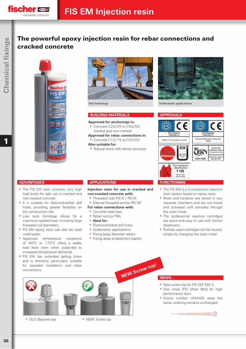
30
Ch
emic
al fi
xin
gs
1
Rail fastenings Underwater applications
The powerful epoxy injection resin for rebar connections and cracked concrete
ADVANTAGES
▪ The FIS EM resin achieves very high load levels for safe use in cracked and non-cracked concrete.
▪ It is suitable for diamond-drilled drill holes, providing greater flexibility on the construction site.
▪ Low resin shrinkage allows for a maximum applied load, including large threaded rod diameters.
▪ FIS EM epoxy resin can also be used underwater.
▪ Approved temperature resistance of -40°C to +72°C offers a stable load level, even when subjected to increased temperature demands.
▪ FIS EM has extended gelling times and is therefore particularly suitable for repeated installation and rebar connections.
APPLICATIONS
Injection resin for use in cracked and non-cracked concrete with:
▪ Threaded rods FIS A / RG M. ▪ Internal threaded anchor RG MI
For rebar connections with: ▪ Concrete steel bars ▪ Rebar anchor FRA ▪ Ideal for: ▪ Diamond-drilled drill holes ▪ Underwater applications ▪ Fixing large diameter rebars ▪ Fixing deep embedment depths
FUNCTIONING
▪ The FIS EM is a 2-component injection resin system based on epoxy resin.
▪ Resin and hardener are stored in two separate chambers and are not mixed and activated until extruded through the static mixer.
▪ The professional injection cartridges are quick and easy to use with fischer dispensers.
▪ Partially used cartridges can be reused, simply by changing the static mixer.
BUILDING MATERIALS
Approved for anchorings in: ▪ Concrete C20/25 to C50/60,
cracked and non-crackedApproved for rebar connections in:
▪ Concrete C12/15 to C50/60Also suitable for:
▪ Natural stone with dense structure
APPROVALS
FIS EM Injection resin
NEW Screw top!
NEWS....
▪ New screw top for FIS EM 390 S. ▪ One mixer (FIS Mixer Red) for high
performance resin. ▪ Article number (96448) stays the
same, ordering remains unchanged.
▪ OLD: Bayonet top ▪ NEW: Screw top
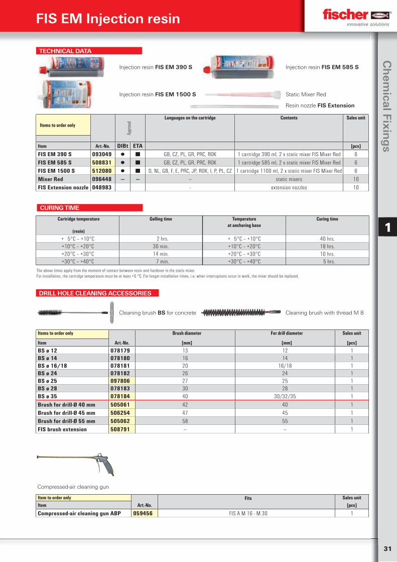
31
Ch
emical Fixin
gs
1
DRILL HOLE CLEANING ACCESSORIES
Cleaning brush BS for concrete Cleaning brush with thread M 8
Items to order only Brush diameter For drill diameter Sales unit
Item Art.-No. [mm] [mm] [pcs]
BS ø 12 078179 13 12 1BS ø 14 078180 16 14 1BS ø 16/18 078181 20 16/18 1BS ø 24 078182 26 24 1BS ø 25 097806 27 25 1BS ø 28 078183 30 28 1BS ø 35 078184 40 30/32/35 1Brush for drill-Ø 40 mm 505061 42 40 1Brush for drill-Ø 45 mm 506254 47 45 1Brush for drill-Ø 55 mm 505062 58 55 1FIS brush extension 508791 — — 1
TECHNICAL DATA
Injection resin FIS EM 390 S Injection resin FIS EM 585 S
Injection resin FIS EM 1500 S Static Mixer Red
Items to order only
Appr
oval
Languages on the cartridge Contents Sales unit
Item Art.-No. DIBt ETA [pcs]
FIS EM 390 S 093049 ▯ ■ GB, CZ, PL, GR, PRC, ROK 1 cartridge 390 ml, 2 x static mixer FIS Mixer Red 6FIS EM 585 S 508831 ▯ ■ GB, CZ, PL, GR, PRC, ROK 1 cartridge 585 ml, 2 x static mixer FIS Mixer Red 6FIS EM 1500 S 512080 ▯ ■ D, NL, GB, F, E, PRC, JP, ROK, I, P, PL, CZ 1 cartridge 1100 ml, 2 x static mixer FIS Mixer Red 6Mixer Red 096448 — — — static mixers 10FIS Extension nozzle 048983 - extension nozzles 10
5
Cartridge temperature Gelling time Temperatureat anchoring base
Curing time
(resin)
+ 5°C – +10°C 2 hrs. + 5°C – +10°C 40 hrs.+10°C – +20°C 30 min. +10°C – +20°C 18 hrs.+20°C – +30°C 14 min. +20°C – +30°C 10 hrs.+30°C – +40°C 7 min. +30°C – +40°C 5 hrs.
The above times apply from the moment of contact between resin and hardener in the static mixer.For installation, the cartridge temperature must be at least +5 °C. For longer installation times, i.e. when interruptions occur in work, the mixer should be replaced.
CURING TIME
FIS EM Injection resin
Compressed-air cleaning gun
Item to order only Fits Sales unitItem Art.-No. [pcs]
Compressed-air cleaning gun ABP 059456 FIS A M 16 - M 30 1
Resin nozzle FIS Extension
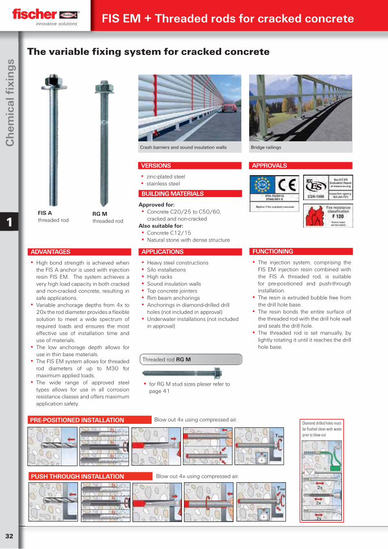
32
Ch
emic
al fi
xin
gs
1
Crash barriers and sound insulation walls Bridge railings
The variable fixing system for cracked concrete
ADVANTAGES
▪ High bond strength is achieved when the FIS A anchor is used with injection resin FIS EM. The system achieves a very high load capacity in both cracked and non-cracked concrete, resulting in safe applications.
▪ Variable anchorage depths from 4x to 20x the rod diameter provides a flexible solution to meet a wide spectrum of required loads and ensures the most effective use of installation time and use of materials.
▪ The low anchorage depth allows for use in thin base materials.
▪ The FIS EM system allows for threaded rod diameters of up to M30 for maximum applied loads.
▪ The wide range of approved steel types allows for use in all corrosion resistance classes and offers maximum application safety.
VERSIONS
▪ zinc-plated steel ▪ stainless steel
APPLICATIONS
▪ Heavy steel constructions ▪ Silo installations ▪ High racks ▪ Sound insulation walls ▪ Top concrete jointers ▪ Rim beam anchorings ▪ Anchorings in diamond-drilled drill
holes (not included in approval) ▪ Underwater installations (not included
in approval)
FUNCTIONING
▪ The injection system, comprising the FIS EM injection resin combined with the FIS A threaded rod, is suitable for pre-positioned and push-through installation.
▪ The resin is extruded bubble free from the drill hole base.
▪ The resin bonds the entire surface of the threaded rod with the drill hole wall and seals the drill hole.
▪ The threaded rod is set manually, by lightly rotating it until it reaches the drill hole base.
BUILDING MATERIALS
Approved for: ▪ Concrete C20/25 to C50/60,
cracked and non-crackedAlso suitable for:
▪ Concrete C12/15 ▪ Natural stone with dense structure
APPROVALS
FIS EM + Threaded rods for cracked concrete
FIS A threaded rod
RG M threaded rod
▪ for RG M stud sizes pleser refer to page 41
Threaded rod RG M
Diamond drilled holes must be flushed clean with water prior to blow out
Blow out 4x using compressed air.PRE-POSITIONED INSTALLATION
PUSH THROUGH INSTALLATION Blow out 4x using compressed air.
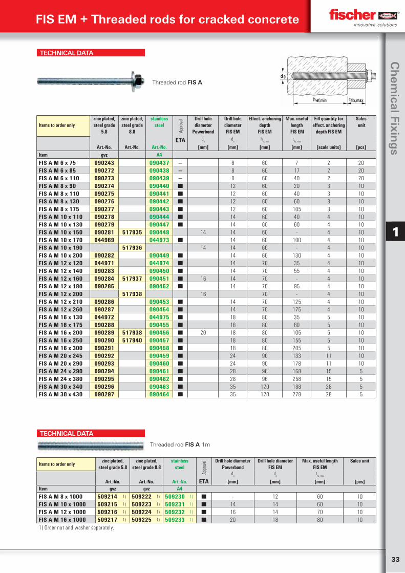
33
Ch
emical Fixin
gs
1
TECHNICAL DATA
Items to order onlyzinc plated, steel grade
5.8
zinc plated, steel grade
8.8
stainless steel
Appr
oval Drill hole
diameter Powerbond
Drill hole diameter FIS EM
Effect. anchoring depth
FIS EM
Max. useful length
FIS EM
Fill quantity for effect. anchoring
depth FIS EM
Sales unit
ETA do
do
hef, min
tfix, max
Art.-No. Art.-No. Art.-No. [mm] [mm] [mm] [mm] [scale units] [pcs]Item gvz A4
FIS A M 6 x 75 090243 090437 — 8 60 7 2 20FIS A M 6 x 85 090272 090438 — 8 60 17 2 20FIS A M 6 x 110 090273 090439 — 8 60 40 2 20FIS A M 8 x 90 090274 090440 ■ 12 60 20 3 10FIS A M 8 x 110 090275 090441 ■ 12 60 40 3 10FIS A M 8 x 130 090276 090442 ■ 12 60 60 3 10FIS A M 8 x 175 090277 090443 ■ 12 60 105 3 10FIS A M 10 x 110 090278 090444 ■ 14 60 40 4 10FIS A M 10 x 130 090279 090447 ■ 14 60 60 4 10FIS A M 10 x 150 090281 517935 090448 14 14 60 - 4 10FIS A M 10 x 170 044969 044973 ■ 14 60 100 4 10FIS A M 10 x 190 517936 14 14 60 - 4 10FIS A M 10 x 200 090282 090449 ■ 14 60 130 4 10FIS A M 12 x 120 044971 044974 ■ 14 70 35 4 10FIS A M 12 x 140 090283 090450 ■ 14 70 55 4 10FIS A M 12 x 160 090284 517937 090451 ■ 16 14 70 - 4 10FIS A M 12 x 180 090285 090452 ■ 14 70 95 4 10FIS A M 12 x 200 517938 16 70 - 4 10FIS A M 12 x 210 090286 090453 ■ 14 70 125 4 10FIS A M 12 x 260 090287 090454 ■ 14 70 175 4 10FIS A M 16 x 130 044972 044975 ■ 18 80 35 5 10FIS A M 16 x 175 090288 090455 ■ 18 80 80 5 10FIS A M 16 x 200 090289 517938 090456 ■ 20 18 80 105 5 10FIS A M 16 x 250 090290 517940 090457 ■ 18 80 155 5 10FIS A M 16 x 300 090291 090458 ■ 18 80 205 5 10FIS A M 20 x 245 090292 090459 ■ 24 90 133 11 10FIS A M 20 x 290 090293 090460 ■ 24 90 178 11 10FIS A M 24 x 290 090294 090461 ■ 28 96 168 15 5FIS A M 24 x 380 090295 090462 ■ 28 96 258 15 5FIS A M 30 x 340 090296 090463 ■ 35 120 188 28 5FIS A M 30 x 430 090297 090464 ■ 35 120 278 28 5
TECHNICAL DATA
Threaded rod FIS A 1m
Items to order onlyzinc plated,
steel grade 5.8zinc plated,
steel grade 8.8stainless
steel
Appr
oval Drill hole diameter
PowerbondDrill hole diameter
FIS EMMax. useful length
FIS EMSales unit
do
do
tfix, max
Art.-No. Art.-No. Art.-No. ETA [mm] [mm] [mm] [pcs]Item gvz gvz A4
FIS A M 8 x 1000 509214 1) 509222 1) 509230 1) ■ - 12 60 10FIS A M 10 x 1000 509215 1) 509223 1) 509231 1) ■ 14 14 60 10FIS A M 12 x 1000 509216 1) 509224 1) 509232 1) ■ 16 14 70 10FIS A M 16 x 1000 509217 1) 509225 1) 509233 1) ■ 20 18 80 101) Order nut and washer separately.
Threaded rod FIS A
FIS EM + Threaded rods for cracked concrete
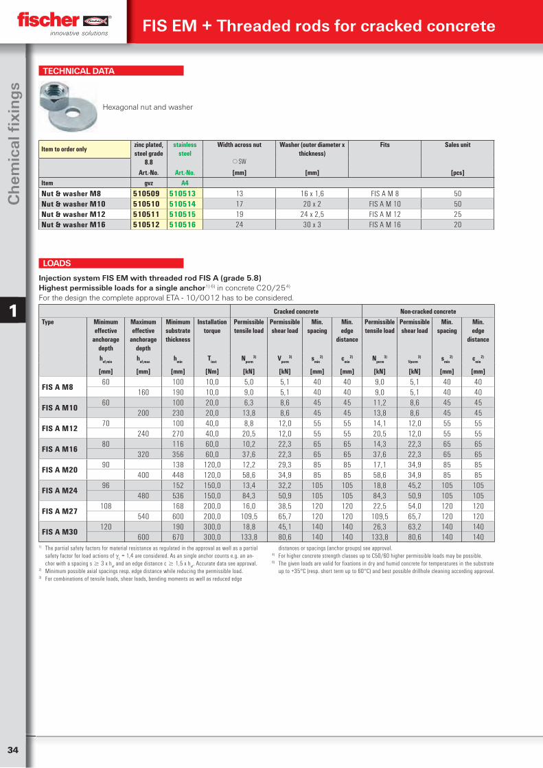
34
Ch
emic
al fi
xin
gs
1
TECHNICAL DATA
Hexagonal nut and washer
Item to order onlyzinc plated, steel grade
8.8
stainless steel
Width across nut Washer (outer diameter x thickness)
Fits Sales unit
SW
Art.-No. Art.-No. [mm] [mm] [pcs]Item gvz A4
Nut & washer M8 510509 510513 13 16 x 1,6 FIS A M 8 50Nut & washer M10 510510 510514 17 20 x 2 FIS A M 10 50Nut & washer M12 510511 510515 19 24 x 2,5 FIS A M 12 25Nut & washer M16 510512 510516 24 30 x 3 FIS A M 16 20
Cracked concrete Non-cracked concreteType Minimum
effective anchorage
depth
Maximumeffective
anchorage depth
Minimum substrate thickness
Installation torque
Permissible tensile load
Permissibleshear load
Min. spacing
Min.edge
distance
Permissible tensile load
Permissibleshear load
Min. spacing
Min.edge
distance
hef,min hef,max hmin Tinst Nperm3) Vperm
3) smin2) cmin
2) Nperm3)
Vperm3) smin
2) cmin2)
[mm] [mm] [mm] [Nm] [kN] [kN] [mm] [mm] [kN] [kN] [mm] [mm]
FIS A M860 100 10,0 5,0 5,1 40 40 9,0 5,1 40 40
160 190 10,0 9,0 5,1 40 40 9,0 5,1 40 40
FIS A M1060 100 20,0 6,3 8,6 45 45 11,2 8,6 45 45
200 230 20,0 13,8 8,6 45 45 13,8 8,6 45 45
FIS A M1270 100 40,0 8,8 12,0 55 55 14,1 12,0 55 55
240 270 40,0 20,5 12,0 55 55 20,5 12,0 55 55
FIS A M1680 116 60,0 10,2 22,3 65 65 14,3 22,3 65 65
320 356 60,0 37,6 22,3 65 65 37,6 22,3 65 65
FIS A M2090 138 120,0 12,2 29,3 85 85 17,1 34,9 85 85
400 448 120,0 58,6 34,9 85 85 58,6 34,9 85 85
FIS A M2496 152 150,0 13,4 32,2 105 105 18,8 45,2 105 105
480 536 150,0 84,3 50,9 105 105 84,3 50,9 105 105
FIS A M27108 168 200,0 16,0 38,5 120 120 22,5 54,0 120 120
540 600 200,0 109,5 65,7 120 120 109,5 65,7 120 120
FIS A M30120 190 300,0 18,8 45,1 140 140 26,3 63,2 140 140
600 670 300,0 133,8 80,6 140 140 133,8 80,6 140 140
Injection system FIS EM with threaded rod FIS A (grade 5.8)Highest permissible loads for a single anchor1) 6) in concrete C20/254)
For the design the complete approval ETA - 10/0012 has to be considered.
1) The partial safety factors for material resistance as regulated in the approval as well as a partial safety factor for load actions of
L = 1,4 are considered. As an single anchor counts e.g. an an-
chor with a spacing s 3 x hef and an edge distance c 1,5 x h
ef. Accurate data see approval.
2) Minimum possible axial spacings resp. edge distance while reducing the permissible load.3) For combinations of tensile loads, shear loads, bending moments as well as reduced edge
distances or spacings (anchor groups) see approval.4) For higher concrete strength classes up to C50/60 higher permissible loads may be possible.6) The given loads are valid for fixations in dry and humid concrete for temperatures in the substrate
up to +35°C (resp. short term up to 60°C) and best possible drillhole cleaning according approval.
LOADS
FIS EM + Threaded rods for cracked concrete
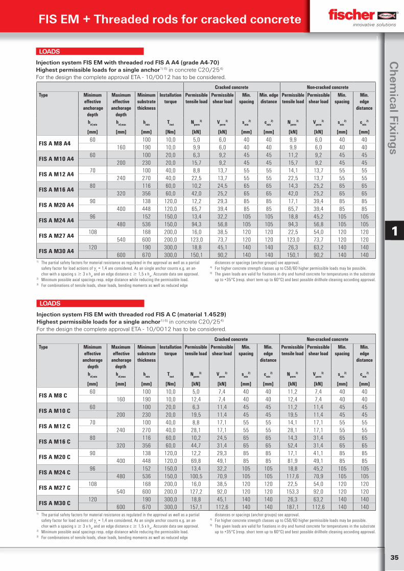
35
Ch
emical Fixin
gs
1
Cracked concrete Non-cracked concreteType Minimum
effective anchorage
depth
Maximumeffective
anchorage depth
Minimum substrate thickness
Installation torque
Permissible tensile load
Permissible shear load
Min. spacing
Min. edge distance
Permissible tensile load
Permissible shear load
Min. spacing
Min.edge
distance
hef,min hef,max hmin Tinst Nperm3) Vperm
3) smin2) cmin
2) Nperm3) Vperm
3) smin2) cmin
2)
[mm] [mm] [mm] [Nm] [kN] [kN] [mm] [mm] [kN] [kN] [mm] [mm]
FIS A M8 A460 100 10,0 5,0 6,0 40 40 9,9 6,0 40 40
160 190 10,0 9,9 6,0 40 40 9,9 6,0 40 40
FIS A M10 A460 100 20,0 6,3 9,2 45 45 11,2 9,2 45 45
200 230 20,0 15,7 9,2 45 45 15,7 9,2 45 45
FIS A M12 A470 100 40,0 8,8 13,7 55 55 14,1 13,7 55 55
240 270 40,0 22,5 13,7 55 55 22,5 13,7 55 55
FIS A M16 A480 116 60,0 10,2 24,5 65 65 14,3 25,2 65 65
320 356 60,0 42,0 25,2 65 65 42,0 25,2 65 65
FIS A M20 A490 138 120,0 12,2 29,3 85 85 17,1 39,4 85 85
400 448 120,0 65,7 39,4 85 85 65,7 39,4 85 85
FIS A M24 A496 152 150,0 13,4 32,2 105 105 18,8 45,2 105 105
480 536 150,0 94,3 56,8 105 105 94,3 56,8 105 105
FIS A M27 A4108 168 200,0 16,0 38,5 120 120 22,5 54,0 120 120
540 600 200,0 123,0 73,7 120 120 123,0 73,7 120 120
FIS A M30 A4120 190 300,0 18,8 45,1 140 140 26,3 63,2 140 140
600 670 300,0 150,1 90,2 140 140 150,1 90,2 140 140
Injection system FIS EM with threaded rod FIS A A4 (grade A4-70)Highest permissible loads for a single anchor1) 6) in concrete C20/254)
For the design the complete approval ETA - 10/0012 has to be considered.
1) The partial safety factors for material resistance as regulated in the approval as well as a partial safety factor for load actions of
L = 1,4 are considered. As an single anchor counts e.g. an an-
chor with a spacing s 3 x hef and an edge distance c 1,5 x h
ef. Accurate data see approval.
2) Minimum possible axial spacings resp. edge distance while reducing the permissible load.3) For combinations of tensile loads, shear loads, bending moments as well as reduced edge
distances or spacings (anchor groups) see approval.4) For higher concrete strength classes up to C50/60 higher permissible loads may be possible.6) The given loads are valid for fixations in dry and humid concrete for temperatures in the substrate
up to +35°C (resp. short term up to 60°C) and best possible drillhole cleaning according approval.
LOADS
Cracked concrete Non-cracked concreteType Minimum
effective anchorage
depth
Maximum effective
anchorage depth
Minimum substrate thickness
Installation torque
Permissible tensile load
Permissibleshear load
Min. spacing
Min.edge
distance
Permissible tensile load
Permissibleshear load
Min. spacing
Min.edge
distance
hef,min hef,max hmin Tinst Nperm3) Vperm
3) smin2) cmin
2) Nperm3) Vperm
3) smin2) cmin
2)
[mm] [mm] [mm] [Nm] [kN] [kN] [mm] [mm] [kN] [kN] [mm] [mm]
FIS A M8 C60 100 10,0 5,0 7,4 40 40 11,2 7,4 40 40
160 190 10,0 12,4 7,4 40 40 12,4 7,4 40 40
FIS A M10 C60 100 20,0 6,3 11,4 45 45 11,2 11,4 45 45
200 230 20,0 19,5 11,4 45 45 19,5 11,4 45 45
FIS A M12 C70 100 40,0 8,8 17,1 55 55 14,1 17,1 55 55
240 270 40,0 28,1 17,1 55 55 28,1 17,1 55 55
FIS A M16 C80 116 60,0 10,2 24,5 65 65 14,3 31,4 65 65
320 356 60,0 44,7 31,4 65 65 52,4 31,4 65 65
FIS A M20 C90 138 120,0 12,2 29,3 85 85 17,1 41,1 85 85
400 448 120,0 69,8 49,1 85 85 81,9 49,1 85 85
FIS A M24 C96 152 150,0 13,4 32,2 105 105 18,8 45,2 105 105
480 536 150,0 100,5 70,9 105 105 117,6 70,9 105 105
FIS A M27 C108 168 200,0 16,0 38,5 120 120 22,5 54,0 120 120
540 600 200,0 127,2 92,0 120 120 153,3 92,0 120 120
FIS A M30 C120 190 300,0 18,8 45,1 140 140 26,3 63,2 140 140
600 670 300,0 157,1 112,6 140 140 187,1 112,6 140 140
Injection system FIS EM with threaded rod FIS A C (material 1.4529)Highest permissible loads for a single anchor1) 6) in concrete C20/254)
For the design the complete approval ETA - 10/0012 has to be considered.
1) The partial safety factors for material resistance as regulated in the approval as well as a partial safety factor for load actions of
L = 1,4 are considered. As an single anchor counts e.g. an an-
chor with a spacing s 3 x hef and an edge distance c 1,5 x h
ef. Accurate data see approval.
2) Minimum possible axial spacings resp. edge distance while reducing the permissible load.3) For combinations of tensile loads, shear loads, bending moments as well as reduced edge
distances or spacings (anchor groups) see approval.4) For higher concrete strength classes up to C50/60 higher permissible loads may be possible.6) The given loads are valid for fixations in dry and humid concrete for temperatures in the substrate
up to +35°C (resp. short term up to 60°C) and best possible drillhole cleaning according approval.
LOADS
FIS EM + Threaded rods for cracked concrete
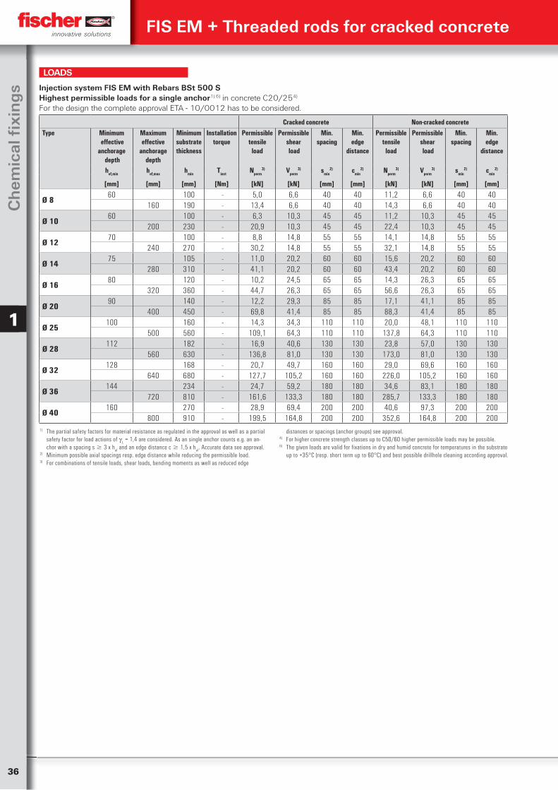
36
Ch
emic
al fi
xin
gs
1
Cracked concrete Non-cracked concreteType Minimum
effective anchorage
depth
Maximum effective
anchorage depth
Minimum substrate thickness
Installation torque
Permissible tensile
load
Permissible shear load
Min. spacing
Min.edge
distance
Permissible tensile
load
Permissible shear load
Min. spacing
Min.edge
distance
hef,min hef,max hmin Tinst Nperm3) Vperm
3) smin2) cmin
2) Nperm3) Vperm
3) smin2) cmin
2)
[mm] [mm] [mm] [Nm] [kN] [kN] [mm] [mm] [kN] [kN] [mm] [mm]
Ø 860 100 - 5,0 6,6 40 40 11,2 6,6 40 40
160 190 - 13,4 6,6 40 40 14,3 6,6 40 40
Ø 1060 100 - 6,3 10,3 45 45 11,2 10,3 45 45
200 230 - 20,9 10,3 45 45 22,4 10,3 45 45
Ø 1270 100 - 8,8 14,8 55 55 14,1 14,8 55 55
240 270 - 30,2 14,8 55 55 32,1 14,8 55 55
Ø 1475 105 - 11,0 20,2 60 60 15,6 20,2 60 60
280 310 - 41,1 20,2 60 60 43,4 20,2 60 60
Ø 1680 120 - 10,2 24,5 65 65 14,3 26,3 65 65
320 360 - 44,7 26,3 65 65 56,6 26,3 65 65
Ø 2090 140 - 12,2 29,3 85 85 17,1 41,1 85 85
400 450 - 69,8 41,4 85 85 88,3 41,4 85 85
Ø 25100 160 - 14,3 34,3 110 110 20,0 48,1 110 110
500 560 - 109,1 64,3 110 110 137,8 64,3 110 110
Ø 28112 182 - 16,9 40,6 130 130 23,8 57,0 130 130
560 630 - 136,8 81,0 130 130 173,0 81,0 130 130
Ø 32128 168 - 20,7 49,7 160 160 29,0 69,6 160 160
640 680 - 127,7 105,2 160 160 226,0 105,2 160 160
Ø 36144 234 - 24,7 59,2 180 180 34,6 83,1 180 180
720 810 - 161,6 133,3 180 180 285,7 133,3 180 180
Ø 40160 270 - 28,9 69,4 200 200 40,6 97,3 200 200
800 910 - 199,5 164,8 200 200 352,6 164,8 200 200
Injection system FIS EM with Rebars BSt 500 SHighest permissible loads for a single anchor1) 6) in concrete C20/254)
For the design the complete approval ETA - 10/0012 has to be considered.
1) The partial safety factors for material resistance as regulated in the approval as well as a partial safety factor for load actions of
L = 1,4 are considered. As an single anchor counts e.g. an an-
chor with a spacing s 3 x hef and an edge distance c 1,5 x h
ef. Accurate data see approval.
2) Minimum possible axial spacings resp. edge distance while reducing the permissible load.3) For combinations of tensile loads, shear loads, bending moments as well as reduced edge
distances or spacings (anchor groups) see approval.4) For higher concrete strength classes up to C50/60 higher permissible loads may be possible.6) The given loads are valid for fixations in dry and humid concrete for temperatures in the substrate
up to +35°C (resp. short term up to 60°C) and best possible drillhole cleaning according approval.
LOADS
FIS EM + Threaded rods for cracked concrete
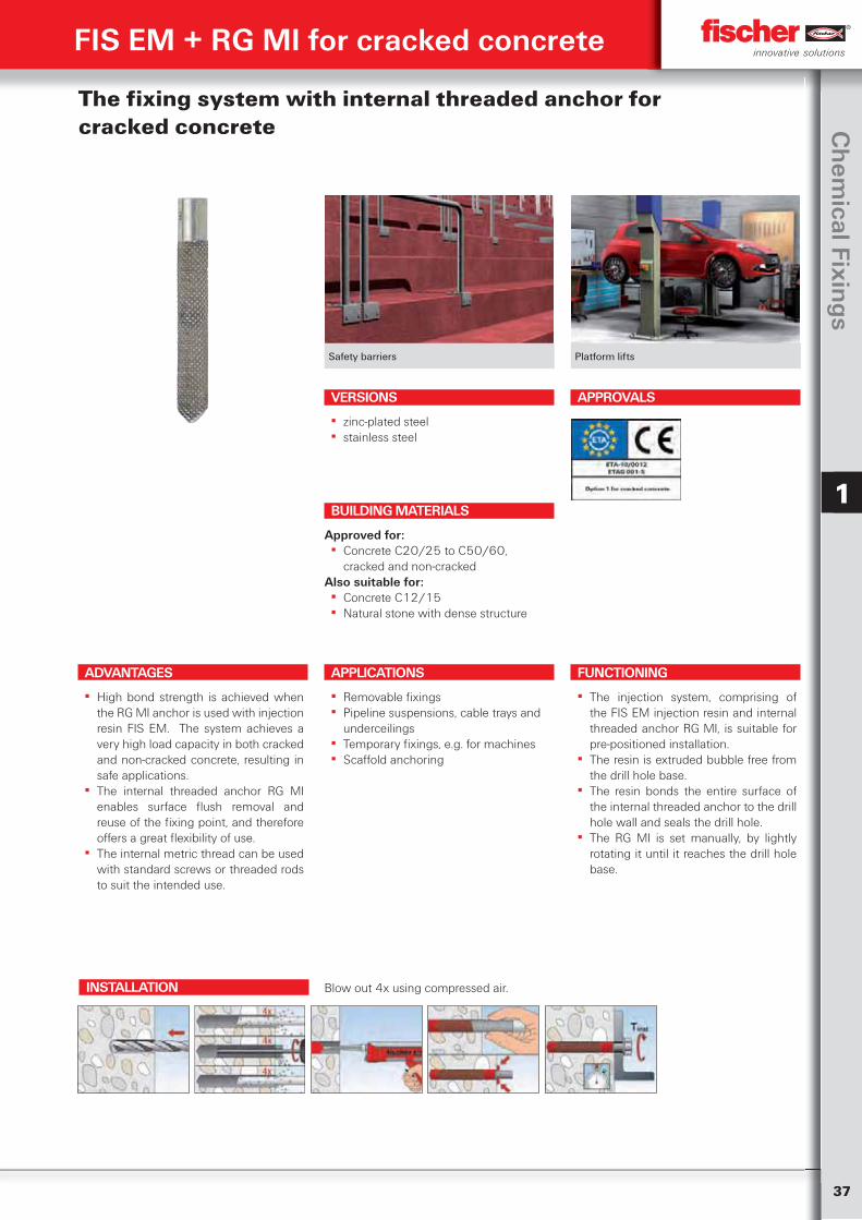
37
Ch
emical Fixin
gs
1
Safety barriers Platform lifts
The fixing system with internal threaded anchor for cracked concrete
ADVANTAGES
▪ High bond strength is achieved when the RG MI anchor is used with injection resin FIS EM. The system achieves a very high load capacity in both cracked and non-cracked concrete, resulting in safe applications.
▪ The internal threaded anchor RG MI enables surface flush removal and reuse of the fixing point, and therefore offers a great flexibility of use.
▪ The internal metric thread can be used with standard screws or threaded rods to suit the intended use.
VERSIONS
▪ zinc-plated steel ▪ stainless steel
APPLICATIONS
▪ Removable fixings ▪ Pipeline suspensions, cable trays and
underceilings ▪ Temporary fixings, e.g. for machines ▪ Scaffold anchoring
FUNCTIONING
▪ The injection system, comprising of the FIS EM injection resin and internal threaded anchor RG MI, is suitable for pre-positioned installation.
▪ The resin is extruded bubble free from the drill hole base.
▪ The resin bonds the entire surface of the internal threaded anchor to the drill hole wall and seals the drill hole.
▪ The RG MI is set manually, by lightly rotating it until it reaches the drill hole base.
BUILDING MATERIALS
Approved for: ▪ Concrete C20/25 to C50/60,
cracked and non-crackedAlso suitable for:
▪ Concrete C12/15 ▪ Natural stone with dense structure
APPROVALS
INSTALLATION
FIS EM + RG MI for cracked concrete
Blow out 4x using compressed air.
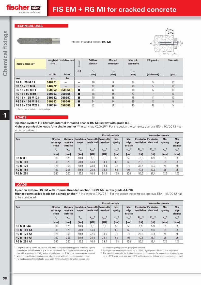
38
Ch
emic
al fi
xin
gs
1
TECHNICAL DATA
Internal threaded anchor RG MI
Items to order onlyzinc-plated
steelstainless steel
Appr
oval Drill hole
diameterMin. bolt
penetrationMax. bolt
penetrationFill quantity Sales unit
ETA do
lE,min
lE,max
Art.-No. Art.-No. [mm] [mm] [mm] [scale units] [pcs]Item gvz A4
RG 8 x 75 M 5 I 048221 1) — — 10 8 14 5 10RG 10 x 75 M 6 I 048222 1) — — 12 10 16 5 10RG 12 x 90 M8 I 050552 1) 050565 1) ■ 14 12 18 5 10RG 16 x 90 M10 I 050553 1) 050566 1) ■ 18 15 23 7 10RG 18 x 125 M12 I 050562 1) 050567 1) ■ 20 18 26 11 10RG 22 x 160 M16 I 050563 1) 050568 1) ■ 24 24 35 17 5RG 28 x 200 M20 I 050564 1) 050569 1) ■ 32 30 45 48 51) Setting tool is included in each package.
Cracked concrete Non-cracked concreteType Effective
anchorage depth
Minimum substrate thickness
Installation torque
Permissible tensile load
Permissible shear load
Min.spacing
Min.edge
distance
Permissible tensile load
Permissible shear load
Min.spacing
Min.edge
distancehef hmin Tinst Nperm
3) Vperm3) smin
2) cmin2) Nperm
3) Vperm3) smin
2) cmin2)
[mm] [mm] [Nm] [kN] [kN] [mm] [mm] [kN] [kN] [mm] [mm]
RG M 8 I 90 120 10,0 9,5 8,3 55 55 13,8 8,3 55 55RG M 10 I 90 125 20,0 14,3 13,3 65 65 20,5 13,3 65 65RG M 12 I 125 165 40,0 23,8 19,3 75 75 32,4 19,3 75 75RG M 16 I 160 205 80,0 28,9 30,9 95 95 40,6 30,9 95 95RG M 20 I 200 260 120,0 40,4 51,4 125 125 56,7 51,4 125 125
Injection system FIS EM with internal threaded anchor RG MI (screw with grade 8.8)Highest permissible loads for a single anchor1) 6) in concrete C20/254). For the design the complete approval ETA - 10/0012 has to be considered.
LOADS
Cracked concrete Non-cracked concreteType Effective
anchorage depth
Minimum substrate thickness
Installation torque
Permissible tensile load
Permissible shear load
Min.spacing
Min.edge
distance
Permissible tensile load
Permissible shear load
Min.spacing
Min.edge
distancehef hmin Tinst Nperm
3) Vperm3) smin
2) cmin2) Nperm
3) Vperm3) smin
2) cmin2)
[mm] [mm] [Nm] [kN] [kN] [mm] [mm] [kN] [kN] [mm] [mm]
RG M 8 I A4 90 120 10,0 9,5 5,9 55 55 9,9 5,9 55 55RG M 10 I A4 90 125 20,0 14,3 9,3 65 65 15,7 9,3 65 65RG M 12 I A4 125 165 40,0 22,5 13,5 75 75 22,5 13,5 75 75RG M 16 I A4 160 205 80,0 28,9 25,1 95 95 40,6 25,1 95 95RG M 20 I A4 200 260 120,0 40,4 39,4 125 125 56,7 39,4 125 125
Injection system FIS EM with internal threaded anchor RG MI A4 (screw grade A4-70)Highest permissible loads for a single anchor1) 6) in concrete C20/254) For the design the complete approval ETA - 10/0012 has to be considered.
LOADS
1) The partial safety factors for material resistance as regulated in the approval as well as a partial safety factor for load actions of
L = 1,4 are considered. As an single anchor counts e.g. an an-
chor with a spacing s 3 x hef and an edge distance c 1,5 x h
ef. Accurate data see approval.
2) Minimum possible axial spacings resp. edge distance while reducing the permissible load.3) For combinations of tensile loads, shear loads, bending moments as well as reduced edge
distances or spacings (anchor groups) see approval.4) For higher concrete strength classes up to C50/60 higher permissible loads may be possible.6) The given loads are valid for fixations in dry and humid concrete for temperatures in the substrate
up to +35°C (resp. short term up to 60°C) and best possible drillhole cleaning according approval.
FIS EM + RG MI for cracked concrete
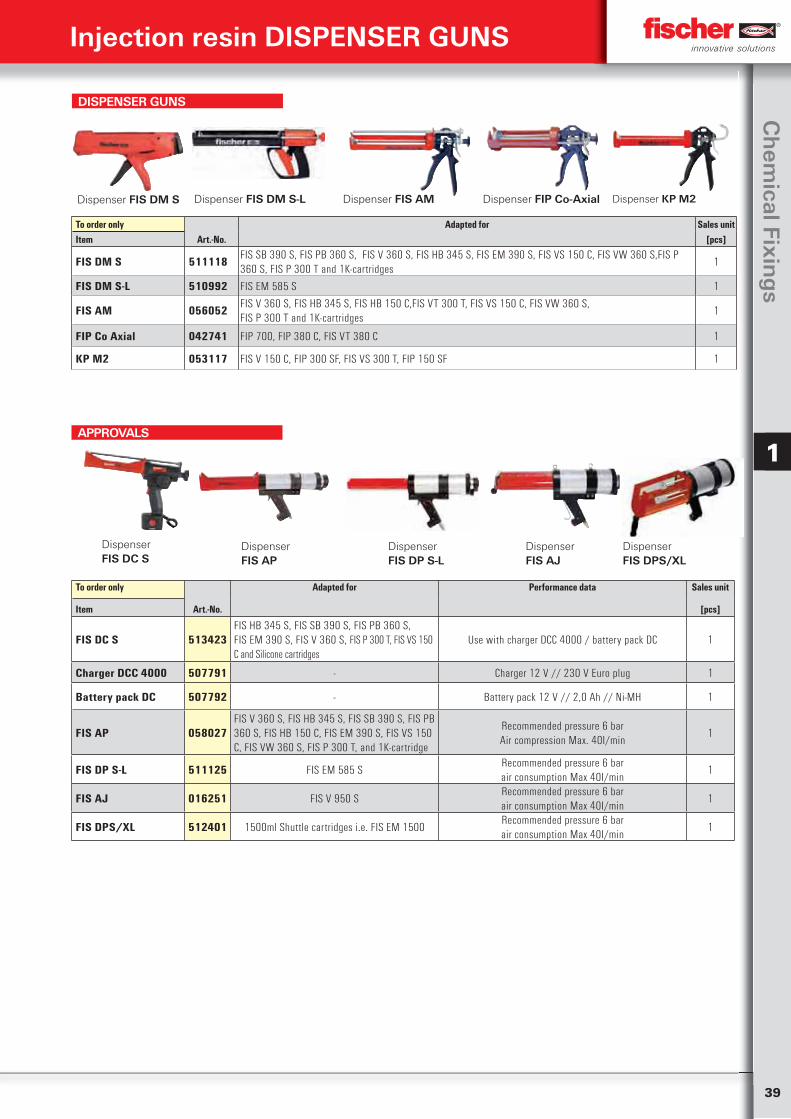
39
Ch
emical Fixin
gs
1
Injection resin DISPENSER GUNS
DispenserFIS DPS/XL
To order only Adapted for Performance data Sales unit
Item Art.-No. [pcs]
FIS DC S 513423FIS HB 345 S, FIS SB 390 S, FIS PB 360 S,FIS EM 390 S, FIS V 360 S, FIS P 300 T, FIS VS 150 C and Silicone cartridges
Use with charger DCC 4000 / battery pack DC 1
Charger DCC 4000 507791 - Charger 12 V // 230 V Euro plug 1
Battery pack DC 507792 - Battery pack 12 V // 2,0 Ah // Ni-MH 1
FIS AP 058027FIS V 360 S, FIS HB 345 S, FIS SB 390 S, FIS PB 360 S, FIS HB 150 C, FIS EM 390 S, FIS VS 150 C, FIS VW 360 S, FIS P 300 T, and 1K-cartridge
Recommended pressure 6 barAir compression Max. 40I/min
1
FIS DP S-L 511125 FIS EM 585 SRecommended pressure 6 barair consumption Max 40I/min
1
FIS AJ 016251 FIS V 950 SRecommended pressure 6 barair consumption Max 40I/min
1
FIS DPS/XL 512401 1500ml Shuttle cartridges i.e. FIS EM 1500Recommended pressure 6 barair consumption Max 40I/min
1
Dispenser FIS DC S
DispenserFIS DP S-L
Dispenser FIS AP
Dispenser FIS AJ
APPROVALS
DISPENSER GUNS
To order only Adapted for Sales unitItem Art.-No. [pcs]
FIS DM S 511118 FIS SB 390 S, FIS PB 360 S, FIS V 360 S, FIS HB 345 S, FIS EM 390 S, FIS VS 150 C, FIS VW 360 S,FIS P 360 S, FIS P 300 T and 1K-cartridges
1
FIS DM S-L 510992 FIS EM 585 S 1
FIS AM 056052FIS V 360 S, FIS HB 345 S, FIS HB 150 C,FIS VT 300 T, FIS VS 150 C, FIS VW 360 S, FIS P 300 T and 1K-cartridges
1
FIP Co Axial 042741 FIP 700, FIP 380 C, FIS VT 380 C 1
KP M2 053117 FIS V 150 C, FIP 300 SF, FIS VS 300 T, FIP 150 SF 1
Dispenser KP M2 Dispenser FIS AMDispenser FIS DM S-L Dispenser FIP Co-Axial Dispenser FIS DM S
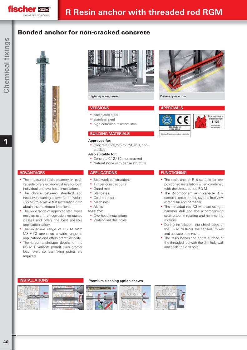
40
Ch
emic
al fi
xin
gs
1
High-bay warehouses Collision protection
Bonded anchor for non-cracked concrete
VERSIONS
▪ zinc-plated steel ▪ stainless steel ▪ high corrosion resistant steel
ADVANTAGES
▪ The measured resin quantity in each capsule offers economical use for both individual and overhead installations.
▪ The choice between standard and intensive cleaning allows for individual choices to achieve fast installation or to obtain the maximum load level.
▪ The wide range of approved steel types ensbles use in all corrosion resistance classes and offers the best possible application safety.
▪ The extensive range of RG M from M8-M30 opens up a wide range of applications and offers great flexibility.
▪ The larger anchorage depths of the RG M E variants permit even greater load levels so less fixing points are required.
APPLICATIONS
▪ Steelwork constructions ▪ Timber constructions ▪ Guard rails ▪ Staircases ▪ Column bases ▪ Machines ▪ Masts
Ideal for: ▪ Overhead installations ▪ Water-filled drill holes
FUNCTIONING
▪ The resin anchor R is suitable for pre-positioned installation when combined with the threaded rod RG M.
▪ The 2-component resin capsule R M contains quick-setting styrene-free vinyl ester resin and hardener.
▪ The threaded rod RG M is set using a hammer drill and the accompanying setting tool in rotating and hammering motions.
▪ During installation, the chisel edge of the RG M destroys the capsule, mixes and activates the resin.
▪ The resin bonds the entire surface of the threaded rod with the drill hole wall and seals the drill hole.
BUILDING MATERIALS
Approved for: ▪ Concrete C20/25 to C50/60, non-
crackedAlso suitable for:
▪ Concrete C12/15, non-cracked ▪ Natural stone with dense structure
APPROVALS
R Resin anchor with threaded rod RGM
INSTALLATIONS Premium cleaning option shown

41
Ch
emical Fixin
gs
1
R Resin anchor with threaded rod RGM
TECHNICAL DATA
Resin capsule R M
Items to order onl
Appr
oval Drill hole diameter Min. drill hole depth Effect. anchoring depth Fits Sales unit
do
h1
hef
Item Art.-No. ETA [mm] [mm] [mm] [pcs]
R M 8 050270 1) ■ 10 80 80 RG M 8 10R M 10 050271 1) ■ 12 90 90 RG M 10 10R M 12 050272 ■ 14 110 110 RG M 12 10R M 12 E 048501 ■ 14 150 150 RG M 12 E 10R M 14 050278 ■ 16 120 120 RG M 14 10R M 16 050273 ■ 18 125 125 RG M 16 10R M 16 E 079838 ■ 18 190 190 RG M 16 E 10R M 20 050274 ■ 25 170 170 RG M 20 10R M 20 E 079840 ■ 25 240 240 RG M 20 E 5R M 22 512763 — 30 190 190 RG M 22 5R M 24 050275 ■ 28 210 210 RG M 24 5R M 24 E 079842 ■ 28 290 290 RG M 24 E 5R M 27 079843 ■ 32 250 250 RG M 27 5R M 30 050276 ■ 35 280 280 RG M 30 51) No ETA-approval in combination with internal-threaded anchor RG MI. E - Extended anchoring depth
Please note: The curing times apply for dry anchoring bases, in damp anchoring bases they should be doubled.
CURING TIME
Temperature at anchoring base Curing time
‒ 5°C – ± 0°C 240 min.± 0°C – +10°C 45 min.+10°C – +20°C 20 min. ≧ +20°C 10 min.
TECHNICAL DATA
Items to order only
zinc-plated steel
zinc-plated steel
stainless steel
Steelhighly
corrosion resistant 1.4529
Appr
oval
Drill hole diameter
Effect. anchoring
depth
Max. fixture thickness
Hexagon drive
Hexagon nut
Fits capsules
Sales unit
do
hef
t fix
6kt SW SW
Art.-No. Art.-No. Art.-No. Art.-No. ETA [mm] [mm] [mm] [mm] [mm] [pcs]Item gvz 8.8 A4
RG M 8 x 110 050256 050263 96316 ■ 10 80 13 5 13 50270 RM 8 10RG M 8 x 150 095698 519443 050293 10 80 60 50270 RM 8 10RG M 8 x 250 095699 095700 ■ 10 80 160 5 13 50270 RM 8 10RG M 10 x 130 050257 050264 96217 ■ 12 90 20 7 17 50270 RM 8 10RG M 10 x 165 050280 050294 ■ 12 90 57 7 17 50271 RM 10 10RG M 10 x 190 050281 050296 ■ 12 90 82 7 17 50271 RM 10 10RG M 10 x 220 - 519444 - 12 90 110 7 17 50271 RM 10 10RG M 10 x 250 095703 ■ 12 90 150 7 17 50271 RM 10 10RG M 10 x 300 — 512246 1) ■ 12 90 200 — 17 50271 RM 10 10RG M 10 x 350 095718 1) 095709 1) ■ 12 90 250 — 17 50271 RM 10 101) Straight cut, setting tool is enclosed. 2) Delivery time on request. 3) Straight cut, additional setting tool required. E - extended anchoring depth
Threaded rod RG M
Continued
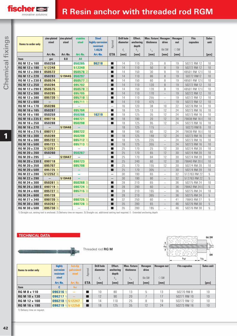
42
Ch
emic
al fi
xin
gs
1
R Resin anchor with threaded rod RGM
Items to order only
zinc-plated steel
zinc-plated steel
stainlessteel
Steelhighly corrosion
resistant 1.4529
Appr
oval
Drill hole diameter
Effect. anchoring
depth
Max. fixture thickness
Hexagon drive
Hexagon nut
Fits capsules
Sales unit
do
hef
t fix
6kt SW SW
Art.-No. Art.-No. Art.-No. Art.-No. ETA [mm] [mm] [mm] [mm] [mm] [pcs]Item gvz 8.8 A4RG M 12 x 160 050258 050265 96218 ■ 14 110 25 8 19 50272 RM 12 10RG M 12 x 180 512248 512249 ■ 14 110 50 8 19 50272 RM 12 10RG M 12 x 200 E 050572 050576 2) ■ 14 150 30 8 19 48501 RM 12 E 10RG M 12 x 220 050283 519445 050297 ■ 14 110 86 8 19 50272 RM12 10RG M 12 x 230 E 050574 050577 2) ■ 14 150 60 8 19 48501 RM 12 E 10RG M 12 x 250 050284 095702 ■ 14 110 120 8 19 50272 RM 12 10RG M 12 x 290 E 050575 050578 2) ■ 14 150 120 8 19 48501 RM 12 E 10RG M 12 x 300 050285 095705 ■ 14 110 170 — 19 50272 RM 12 10RG M 12 x 380 095720 1) 095710 1) ■ 14 110 255 — 19 50272 RM 12 10RG M 12 x 600 — 095711 1) ■ 14 110 475 — 19 50272 RM 12 10RG M 14 x 170 050286 — — 16 120 38 10 22 50278 RM 14 10RG M 16 x 165 050287 095704 ■ 18 125 13 12 24 50273 RM 16 10RG M 16 x 190 050259 050266 16219 ■ 18 125 35 12 24 50273 RM 16 10RG M 16 x 235 E 090716 090721 ■ 18 190 20 12 24 79838 RM 16 E 10RG M 16 x 250 050288 050298 ■ 18 125 95 12 24 50273 RM 16 10RG M 16 x 270 — 519446 — 18 125 115 - - 50273 RM16 10RG M 16 x 275 E 090717 090722 ■ 18 190 60 12 24 79838 RM 16 E 10RG M 16 x 300 050289 050299 ■ 18 125 148 12 24 50273 RM 16 10RG M 16 x 380 095722 1) 095712 1) ■ 18 125 235 — 24 50273 RM 16 10RG M 16 x 500 095723 1) 095713 1) ■ 18 125 355 — 24 50273 RM 16 10RG M 20 x 220 512251 — ■ 25 170 25 12 30 50274 RM 20 10RG M 20 x 260 050260 050267 ■ 25 170 65 12 30 50274 RM 20 10RG M 20 x 295 — 519447 — ■ 25 170 84 12 30 50274 RM 20 10RG M 20 x 330 E 090718 090723 ■ 25 240 60 12 30 79840 RM 20 E 10RG M 20 x 350 095707 095706 ■ 25 170 155 12 30 50274 RM 20 10RG M 20 x 500 095725 3) — ■ 25 170 305 — 30 50274 RM 20 10RG M 22 x 280 512252 3) — — 30 190 65 — 32 512763 RM 22 5RG M 22 x 290 — 519448 — — 30 190 80 — 32 512763 RM 22 5RG M 24 x 300 050261 3) 050268 3) ■ 28 210 65 — 36 50275 RM 24 10RG M 24 x 380 E 090719 3) 090724 3) ■ 28 290 60 — 36 79842 RM 24 E 5RG M 24 x 400 095727 3) 095715 3) ■ 28 210 165 — 36 50275 RM 24 10RG M 24 x 600 095728 — ■ 28 210 365 — 36 50275 RM 24 5RG M 27 x 340 090720 3) 090725 3) ■ 32 250 60 — 41 79843 RM 27 5RG M 30 x 380 050262 3) 090726 3) ■ 35 280 65 — 46 50276 RM 30 5RG M 30 x 500 095730 3) — ■ 35 280 185 — 46 50276 RM 30 51) Straight cut, setting tool is enclosed. 2) Delivery time on request. 3) Straight cut, additional setting tool required. E - Extended anchoring depth
TECHNICAL DATA
Threaded rod RG M
Items to order onlyhighly
corrosion resistant
steel
hot-dip galvanised
steel Appr
oval
Drill hole diameter
Effect. anchoring
depth
Max. fixture thickness
Hexagon drive
Hexagon nut Fits capsules Sales unit
do
hef
t fix
6kt SW SW
Art.-No. Art.-No. ETA [mm] [mm] [mm] [mm] [mm] [pcs]Item C fvz
RG M 8 x 110 096316 1) — ■ 10 80 13 5 13 50270 RM 8 10RG M 10 x 130 096217 1) — ■ 12 90 20 7 17 50271 RM 10 10RG M 12 x 160 096218 1) 512247 ■ 14 110 25 8 19 50272 RM 12 10RG M 16 x 190 096219 1) 512250 ■ 18 125 35 12 24 50273 RM 16 101) Delivery time on request.
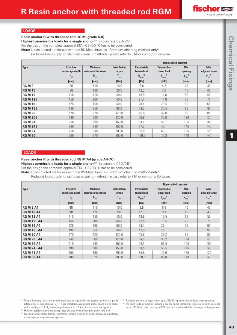
43
Ch
emical Fixin
gs
1
R Resin anchor with threaded rod RGM
Non-cracked concreteType Effective
anchorage depthMinimum
substrate thicknessInstallation
torquePermissibletensile load
Permissibleshear load
Min.spacing
Min.edge distance
hef hmin Tinst Nperm3) Vperm
3) smin2) cmin
2)
[mm] [mm] [Nm] [kN] [kN] [mm] [mm]
RG M 8 80 110 10,0 8,8 4,2 40 40RG M 10 90 120 20,0 12,3 7,6 45 45RG M 12 110 150 40,0 19,8 11,0 55 55RG M 12E 150 200 40,0 21,1 11,0 75 75RG M 16 125 160 60,0 28,4 20,5 65 65RG M 16E 190 250 60,0 39,3 20,5 95 95RG M 20 170 220 120,0 45,8 32,0 85 85RG M 20E 240 300 120,0 60,9 32,0 120 120RG M 24 210 280 150,0 64,1 46,1 105 105RG M 24E 290 380 150,0 87,7 46,1 145 145RG M 27 250 330 200,0 85,8 60,1 125 125RG M 30 280 370 300,0 100,5 73,3 140 140
Resin anchor R with threaded rod RG M (grade 5.8)Highest permissible loads for a single anchor1) 6) in concrete C20/254)
For the design the complete approval ETA - 08/0010 has to be considered.Note: Loads quoted are for use with the BS Metal brushes - Premium cleaning method only! Reduced loads apply for standard cleaning methods - please refer to ETA or compufix Software.
LOADS
Non-cracked concreteType Effective
anchorage depthMinimum
substrate thicknessInstallation
torquePermissibletensile load
Permissibleshear load
Min.spacing
Min.edge distance
hef hmin Tinst Nperm3) Vperm
3) smin2) cmin
2)
[mm] [mm] [Nm] [kN] [kN] [mm] [mm]
RG M 8 A4 80 110 10,0 8,8 5,9 40 40RG M 10 A4 90 120 20,0 12,3 9,3 45 45RG M 12 A4 110 150 40,0 19,8 13,5 55 55RG M 12E A4 150 200 40,0 22,5 13,5 75 75RG M 16 A4 125 160 60,0 28,4 25,1 65 65RG M 16E A4 190 250 60,0 42,0 25,1 95 95RG M 20 A4 170 220 120,0 45,8 39,2 85 85RG M 20E A4 240 300 120,0 64,6 39,2 120 120RG M 24 A4 210 280 150,0 64,1 56,5 105 105RG M 24E A4 290 380 150,0 88,5 56,5 145 145RG M 27 A4 250 330 200,0 85,8 73,6 125 125RG M 30 A4 280 370 300,0 100,5 89,8 140 140
Resin anchor R with threaded rod RG M A4 (grade A4-70)Highest permissible loads for a single anchor1) 6) in concrete C20/254)
For the design the complete approval ETA - 08/0010 has to be considered. Note: Loads quoted are for use with the BS Metal brushes - Premium cleaning method only! Reduced loads apply for standard cleaning methods - please refer to ETA or compufix Software.
LOADS
1) The partial safety factors for material resistance as regulated in the approval as well as a partial safety factor for load actions of
L = 1,4 are considered. As an single anchor counts e.g. an anchor
with a spacing s 3 x hef and an edge distance c 1,5 x h
ef. Accurate data see approval.
2) Minimum possible axial spacings resp. edge distance while reducing the permissible load.3) For combinations of tensile loads, shear loads, bending moments as well as reduced edge distances
or spacings (anchor groups) see approval.
4) For higher concrete strength classes up to C50/60 higher permissible loads may be possible.6) The given loads are valid for fixations in dry and humid concrete for temperatures in the substrate
up to +50°C (resp. short term up to 80°C) and best possible drillhole cleaning according approval.
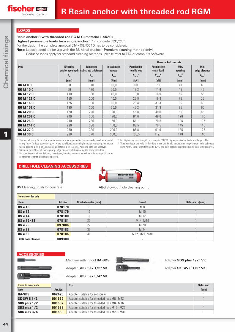
44
Ch
emic
al fi
xin
gs
1
ACCESSORIESMachine setting tool RA-SDS Adapter SDS plus 1/2“ VK
Adapter SDS max 1/2“ VK Adapter SK SW 8 1/2“ VK
Adapter SDS max 3/4“ VK
Items to order only fits Sales unitItem Art.-No. [pcs]
RA-SDS 062420 Adapter suitable for set screw 1SK SW 8 1/2 001536 Adapter suitable for threaded rods M8 - M22 1SDS plus 1/2 001537 Adapter suitable for threaded rods M8 - M16 1SDS max 1/2 001538 Adapter suitable for threaded rods M16 - M20 1SDS max 3/4 001539 Adapter suitable for threaded rods M20 - M30 1
R Resin anchor with threaded rod RGM
Non-cracked concreteType Effective
anchorage depthMinimum
substrate thicknessInstallation
torquePermissibletensile load
Permissibleshear load
Min.spacing
Min.edge distance
hef hmin Tinst Nperm3) Vperm
3) smin2) cmin
2)
[mm] [mm] [Nm] [kN] [kN] [mm] [mm]
RG M 8 C 80 110 10,0 8,8 7,3 40 40RG M 10 C 90 120 20,0 12,3 11,6 45 45RG M 12 C 110 150 40,0 19,8 16,9 55 55RG M 12E C 150 200 40,0 26,9 16,9 75 75RG M 16 C 125 160 60,0 28,4 31,3 65 65RG M 16E C 190 250 60,0 43,2 31,3 95 95RG M 20 C 170 220 120,0 45,8 49,0 85 85RG M 20E C 240 300 120,0 64,6 49,0 120 120RG M 24 C 210 280 150,0 64,1 70,5 105 105RG M 24E C 290 380 150,0 88,5 70,5 145 145RG M 27 C 250 330 200,0 85,8 91,9 125 125RG M 30 C 280 370 300,0 100,5 112,1 140 140
Resin anchor R with threaded rod RG M C (material 1.4529)Highest permissible loads for a single anchor1) 6) in concrete C20/254)
For the design the complete approval ETA - 08/0010 has to be considered. Note: Loads quoted are for use with the BS Metal brushes - Premium cleaning method only! Reduced loads apply for standard cleaning methods - please refer to ETA or compufix Software.
1) The partial safety factors for material resistance as regulated in the approval as well as a partial safety factor for load actions of
L = 1,4 are considered. As an single anchor counts e.g. an anchor
with a spacing s 3 x hef and an edge distance c 1,5 x h
ef. Accurate data see approval.
2) Minimum possible axial spacings resp. edge distance while reducing the permissible load.3) For combinations of tensile loads, shear loads, bending moments as well as reduced edge distances
or spacings (anchor groups) see approval.
4) For higher concrete strength classes up to C50/60 higher permissible loads may be possible.6) The given loads are valid for fixations in dry and humid concrete for temperatures in the substrate
up to +50°C (resp. short term up to 80°C) and best possible drillhole cleaning according approval.
LOADS
Items to order only
Art.-No. Brush diameter [mm] thread Sales units [mm]Item
BS ø 10 078178 11 M 8 1BS ø 12 078179 13 M 10 1BS ø 14 078180 16 M 12 1BS ø 16/18 078181 20 M14, M16 1BS ø 25 097806 27 M 20 1BS ø 28 078183 30 M 24 1BS ø 35 078184 40 M22, M27, M30 1
ABG hole cleaner 089300 - - 1
DRILL HOLE CLEANING ACCESSORIES
BS Cleaning brush for concrete ABG Blow-out hole cleaning pump
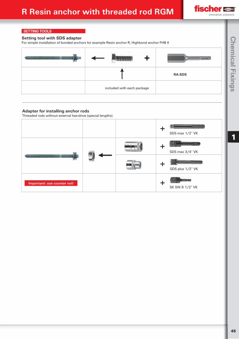
45
Ch
emical Fixin
gs
1
R Resin anchor with threaded rod RGM
SETTING TOOLS
Adapter for installing anchor rodsThreaded rods without external hex-drive (special lengths).
SDS max 1/2“ VK
SDS max 3/4“ VK
SDS plus 1/2“ VK
SK SW 8 1/2“ VK
+
Setting tool with SDS adapterFor simple installation of bonded anchors for example Resin anchor R, Highbond anchor FHB II
← +
RA-SDS
included with each package
←
+
+
+
←
Important: use counter nut!
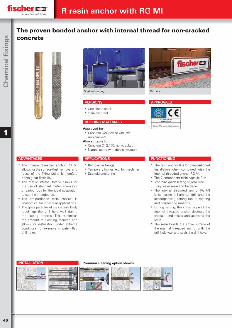
46
Ch
emic
al fi
xin
gs
1
INSTALLATION
Stadium seating Barriers
The proven bonded anchor with internal thread for non-cracked concrete
VERSIONS
▪ zinc-plated steel ▪ stainless steel
ADVANTAGES
▪ The internal threaded anchor RG MI allows for the surface flush removal and reuse of the fixing point. It therefore offers great flexibility.
▪ The metric internal thread allows for the use of standard metric screws or threaded rods for the ideal adaptation to suit the intended use.
▪ The pre-portioned resin capsule is economical for individual applications.
▪ The glass particles of the capsule body rough up the drill hole wall during the setting process. This minimises the amount of cleaning required and allows for installation under extreme conditions, for example in water-filled drill holes.
APPLICATIONS
▪ Removable fixings ▪ Temporary fixings, e.g. for machines ▪ Scaffold anchoring
FUNCTIONING
▪ The resin anchor R is for pre-positioned installation when combined with the internal threaded anchor RG MI.
▪ The 2-component resin capsule R M ▪ contains quick-setting styrene-free
vinyl ester resin and hardener. ▪ The internal threaded anchor RG MI
is set using a hammer drill and the accompanying setting tool in rotating and hammering motions.
▪ During setting, the chisel edge of the internal threaded anchor destroys the capsule, and mixes and activates the resin.
▪ The resin bonds the entire surface of the internal threaded anchor with the drill hole wall and seals the drill hole.
BUILDING MATERIALS
Approved for: ▪ Concrete C20/25 to C50/60
non-crackedAlso suitable for:
▪ Concrete C12/15, non-cracked ▪ Natural stone with dense structure
R resin anchor with RG MI
APPROVALS
Premium cleaning option shown

47
Ch
emical Fixin
gs
1
TECHNICAL DATA
Internal threaded anchor RG MI
Items to order onlyzinc-plated
steelstainless
steel
Appr
oval Drill hole
diameterEffective
anchorage depthMin. bolt
penetrationMax. bolt
penetrationFits
capsulesSales unit
ETA do
lE,min
lE,max
Art.-No. Art.-No. [mm] [mm] [mm] [scale units] [pcs]Item gvz A4
RG 8 x 75 M 5 I 048221 1) — — 10 8 14 5 50270 RM 8 10RG 10 x 75 M 6 I 048222 1) — — 12 10 16 5 50271 RM 10 10RG 12 x 90 M8 I 050552 1) 050565 1) ■ 14 12 18 5 50272 RM 12 10RG 16 x 90 M10 I 050553 1) 050566 1) ■ 18 15 23 7 50278 RM 14 10RG 18 x 125 M12 I 050562 1) 050567 1) ■ 20 18 26 11 79838 RM 16 E 10RG 22 x 160 M16 I 050563 1) 050568 1) ■ 24 24 35 17 79838 RM 16 E 5RG 28 x 200 M20 I 050564 1) 050569 1) ■ 32 30 45 48 50274 RM 20 51) Setting tool is included in each package.
R resin anchor with RG MI
TECHNICAL DATA
Item to order onlyAp
prov
al Drill hole diameter
Min. drill hole depth
Effect. anchoring depth
Fits internal-threaded anchor Sales unit
do
h1
hef
Item Art.-No. ETA [mm] [mm] [mm] [pcs]
R M 14 050278 ■ 16 90 90 RG M10 I 10R M 16 E 079838 ■ 18 125/160 125/160 RG M12 I, RG M16 I 10R M 20 050274 ■ 25 200 200 RG M20 I 10
Please note: The curing times apply for dry anchoring bases, in damp anchoring bases they should be doubled.
CURING TIME
Temperature at anchoring base Curing time
‒ 5°C – ± 0°C 240 min.± 0°C – +10°C 45 min.+10°C – +20°C 20 min. ≧ +20°C 10 min.
Resin capsule R M
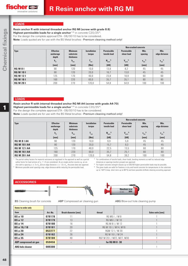
48
Ch
emic
al fi
xin
gs
1
BS Cleaning brush for concrete ABP Compressed air cleaning gun ABG Blow-out hole cleaning pump
Items to order only
Art.-No. Brush diameter [mm] thread Sales units [mm]Item
BS ø 10 078178 11 RG M5 I / M 8 1BS ø 12 078179 13 RG M6 I / M 10 1BS ø 14 078180 16 RG M 8 I / M 12 1BS ø 16/18 078181 20 RG M 10 I / M14, M16 1BS ø 20 052277 22 RGM 12 I / M 20 1BS ø 24 078182 26 RG M 16 I / M 24 1BS ø 35 078184 40 RGF M 20 I / M22, M27, M30 1
ABP compressed air gun 059456 - for RG MI 8 - 30 1
ABG hole cleaner 089300 - 1
ACCESSORIES
R Resin anchor with RG MI
Non-cracked concreteType Effective
anchorage depth
Minimumsubstrate thickness
Installationtorque
Permissibletensile load
Permissibleshear load
Min.spacing
Min.edge distance
hef hmin Tinst Nperm3) Vperm
3) smin2) cmin
2)
[mm] [mm] [Nm] [kN] [kN] [mm] [mm]
RG M 8 I A4 90 120 10,0 9,9 5,9 45 45RG M 10 I A4 90 120 20,0 15,7 9,3 45 45RG M 12 I A4 125 170 40,0 22,5 13,5 60 60RG M 16 I A4 160 220 60,0 35,7 25,1 80 80RG M 20 I A4 200 270 120,0 54,8 39,2 100 100
Resin anchor R with internal threaded anchor RG MI A4 (screw with grade A4-70)Highest permissible loads for a single anchor1) 6) in concrete C20/254). For the design the complete approval ETA - 08/0010 has to be considered.Note: Loads quoted are for use with the BS Metal brushes - Premium cleaning method only!
1) The partial safety factors for material resistance as regulated in the approval as well as a partial safety factor for load actions of
L = 1,4 are considered. As an single anchor counts e.g. an an-
chor with a spacing s 3 x hef and an edge distance c 1,5 x h
ef. Accurate data see approval.
2) Minimum possible axial spacings resp. edge distance while reducing the permissible load.
3) For combinations of tensile loads, shear loads, bending moments as well as reduced edge distances or spacings (anchor groups) see approval.
4) For higher concrete strength classes up to C50/60 higher permissible loads may be possible.6) The given loads are valid for fixations in dry and humid concrete for temperatures in the substrate
up to +50°C (resp. short term up to 80°C) and best possible drillhole cleaning according approval.
LOADS
Non-cracked concreteType Effective
anchorage depth
Minimumsubstrate thickness
Installationtorque
Permissibletensile load
Permissibleshear load
Min.spacing
Min.edge distance
hef hmin Tinst Nperm3) Vperm
3) smin2) cmin
2)
[mm] [mm] [Nm] [kN] [kN] [mm] [mm]
RG M 8 I 90 120 10,0 13,8 8,2 45 45RG M 10 I 90 120 20,0 16,7 13,0 45 45RG M 12 I 125 170 40,0 23,8 18,9 60 60RG M 16 I 160 220 60,0 35,7 35,1 80 80RG M 20 I 200 270 120,0 54,8 54,9 100 100
Resin anchor R with internal threaded anchor RG MI (screw with grade 8.8)Highest permissible loads for a single anchor1) 6) in concrete C20/254). For the design the complete approval ETA - 08/0010 has to be considered. Note: Loads quoted are for use with the BS Metal brushes - Premium cleaning method only!
LOADS
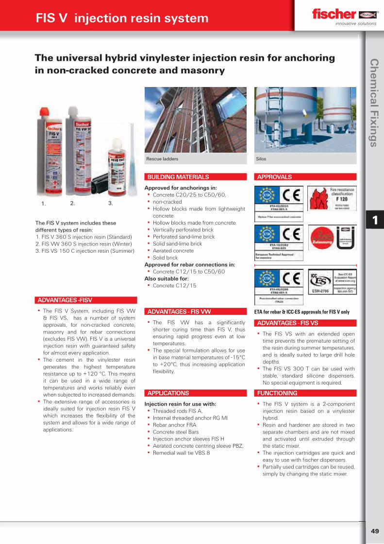
49
Ch
emical Fixin
gs
1
FIS V injection resin system
Rescue ladders Silos
The universal hybrid vinylester injection resin for anchoring in non-cracked concrete and masonry
ADVANTAGES -FISV
▪ The FIS V System, including FIS VW & FIS VS, has a number of system approvals, for non-cracked concrete, masonry and for rebar connections (excludes FIS VW). FIS V is a universal injection resin with guaranteed safety for almost every application.
▪ The cement in the vinylester resin generates the highest temperature resistance up to +120 °C. This means it can be used in a wide range of temperatures and works reliably even when subjected to increased demands.
▪ The extensive range of accessories is ideally suited for injection resin FIS V which increases the flexibility of the system and allows for a wide range of applications.
APPLICATIONS
Injection resin for use with: ▪ Threaded rods FIS A, ▪ Internal threaded anchor RG MI ▪ Rebar anchor FRA ▪ Concrete steel Bars ▪ Injection anchor sleeves FIS H ▪ Aerated concrete centring sleeve PBZ, ▪ Remedial wall tie VBS 8
FUNCTIONING
▪ The FIS V system is a 2-component injection resin based on a vinylester hybrid.
▪ Resin and hardener are stored in two separate chambers and are not mixed and activated until extruded through the static mixer.
▪ The injection cartridges are quick and easy to use with fischer dispensers.
▪ Partially used cartridges can be reused, simply by changing the static mixer.
BUILDING MATERIALS
Approved for anchorings in: ▪ Concrete C20/25 to C50/60, ▪ non-cracked ▪ Hollow blocks made from lightweight
concrete ▪ Hollow blocks made from concrete ▪ Vertically perforated brick ▪ Perforated sand-lime brick ▪ Solid sand-lime brick ▪ Aerated concrete ▪ Solid brick
Approved for rebar connections in: ▪ Concrete C12/15 to C50/60
Also suitable for: ▪ Concrete C12/15
APPROVALS
ETA for rebar & ICC-ES approvals for FIS V onlyADVANTAGES - FIS VW
▪ The FIS VW has a significantly shorter curing time than FIS V, thus ensuring rapid progress even at low temperatures.
▪ The special formulation allows for use in base material temperatures of -15°C to +20°C, thus increasing application flexibility.
ADVANTAGES - FIS VS
▪ The FIS VS with an extended open time prevents the premature setting of the resin during summer temperatures, and is ideally suited to large drill hole depths.
▪ The FIS VS 300 T can be used with stable, standard silicone dispensers. No special equipment is required.
The FIS V system includes these different types of resin:1. FIS V 360 S injection resin (Standard)2. FIS VW 360 S injection resin (Winter)3. FIS VS 150 C injection resin (Summer)
1. 2. 3.
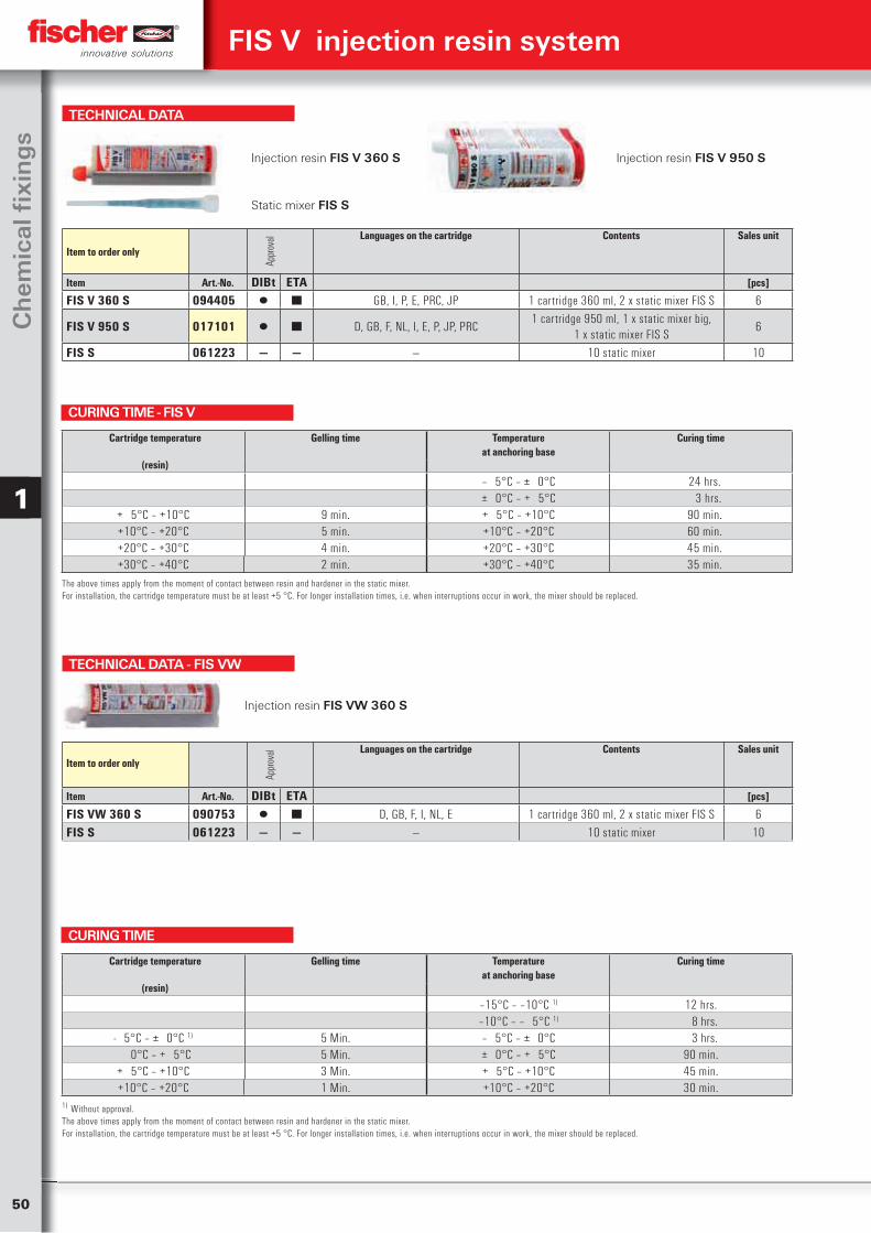
50
Ch
emic
al fi
xin
gs
1
TECHNICAL DATA
Injection resin FIS V 360 S Injection resin FIS V 950 S
Static mixer FIS S
Item to order only
Appr
oval Languages on the cartridge Contents Sales unit
Item Art.-No. DIBt ETA [pcs]
FIS V 360 S 094405 ▯ ■ GB, I, P, E, PRC, JP 1 cartridge 360 ml, 2 x static mixer FIS S 6
FIS V 950 S 017101 ▯ ■ D, GB, F, NL, I, E, P, JP, PRC1 cartridge 950 ml, 1 x static mixer big,
1 x static mixer FIS S6
FIS S 061223 — — — 10 static mixer 10
TECHNICAL DATA - FIS VW
Injection resin FIS VW 360 S
Item to order only
Appr
oval Languages on the cartridge Contents Sales unit
Item Art.-No. DIBt ETA [pcs]
FIS VW 360 S 090753 ▯ ■ D, GB, F, I, NL, E 1 cartridge 360 ml, 2 x static mixer FIS S 6FIS S 061223 — — — 10 static mixer 10
CURING TIME - FIS V
Cartridge temperature Gelling time Temperatureat anchoring base
Curing time
(resin)
‒ 5°C – ± 0°C 24 hrs.± 0°C – + 5°C 3 hrs.
+ 5°C – +10°C 9 min. + 5°C – +10°C 90 min.+10°C – +20°C 5 min. +10°C – +20°C 60 min.+20°C – +30°C 4 min. +20°C – +30°C 45 min.+30°C – +40°C 2 min. +30°C – +40°C 35 min.
The above times apply from the moment of contact between resin and hardener in the static mixer.For installation, the cartridge temperature must be at least +5 °C. For longer installation times, i.e. when interruptions occur in work, the mixer should be replaced.
CURING TIME
1) Without approval.The above times apply from the moment of contact between resin and hardener in the static mixer.For installation, the cartridge temperature must be at least +5 °C. For longer installation times, i.e. when interruptions occur in work, the mixer should be replaced.
Cartridge temperature Gelling time Temperatureat anchoring base
Curing time
(resin)
‒15°C – ‒10°C 1) 12 hrs.‒10°C – ‒ 5°C 1) 8 hrs.
- 5°C – ± 0°C 1) 5 Min. ‒ 5°C – ± 0°C 3 hrs. 0°C – + 5°C 5 Min. ± 0°C – + 5°C 90 min.+ 5°C – +10°C 3 Min. + 5°C – +10°C 45 min.+10°C – +20°C 1 Min. +10°C – +20°C 30 min.
FIS V injection resin system
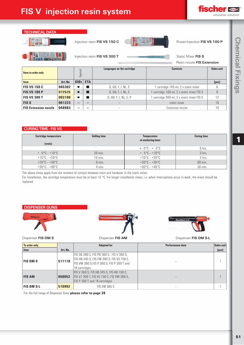
51
Ch
emical Fixin
gs
1
TECHNICAL DATA
Injection resin FIS VS 150 C Power-Injection FIS VS 100 P
Injection resin FIS VS 300 T Static Mixer FIS S
Item to order only
Appr
oval Languages on the cartridge Contents Sales unit
Item Art.-No. DIBt ETA [pcs]
FIS VS 150 C 045302 ▯ ■ D, GB, F, I, NL, E 1 cartridge 145 ml, 2 x static mixer 6FIS VS 100 P 072525 ▯ ■ D, GB, F, I, NL, E 1 cartridge 100 ml, 2 x static mixer FIS S 6
FIS VS 300 T 093180 ▯ ■ D, GB, F, I, NL, E, P 1 cartridge 300 ml, 2 x static mixer FIS S 12
FIS S 061223 — — — static mixer 10FIS Extension nozzle 048983 — — — Extension nozzle 10
CURING TIME - FIS VS
The above times apply from the moment of contact between resin and hardener in the static mixer.For installation, the cartridge temperature must be at least +5 °C. For longer installation times, i.e. when interruptions occur in work, the mixer should be replaced
Cartridge temperature Gelling time Temperatureat anchoring base
Curing time
(resin)
± 0°C – + 5°C 6 hrs.+ 5°C – +10°C 20 min. + 5°C – +10°C 3 hrs.+10°C – +20°C 10 min. +10°C – +20°C 2 hrs.+20°C – +30°C 6 min. +20°C – +30°C 60 min.+30°C – +40°C 4 min. +30°C – +40°C 30 min.
FIS V injection resin system
Resin nozzle FIS Extension
DISPENSER GUNS
Dispenser FIS DM S Dispenser FIS AM Dispenser FIS DM S-L
To order only Adapted for Performance data Sales unitItem Art.-No. [pcs]
FIS DM S 511118
FIS SB 390 S, FIS PB 360 S, FIS V 360 S, FIS HB 345 S, FIS EM 390 S, FIS VS 150 C, FIS VW 360 S,FIS P 360 S, FIS P 300 T and 1K-cartridges
— 1
FIS AM 056052
FIS V 360 S, FIS HB 345 S, FIS HB 150 C, FIS VT 300 T, FIS VS 150 C, FIS VW 360 S, FIS P 300 T and 1K-cartridges
— 1
FIS DM S-L 510992 FIS EM 585 S - 1
For the full range of Dispenser Guns please refer to page 39
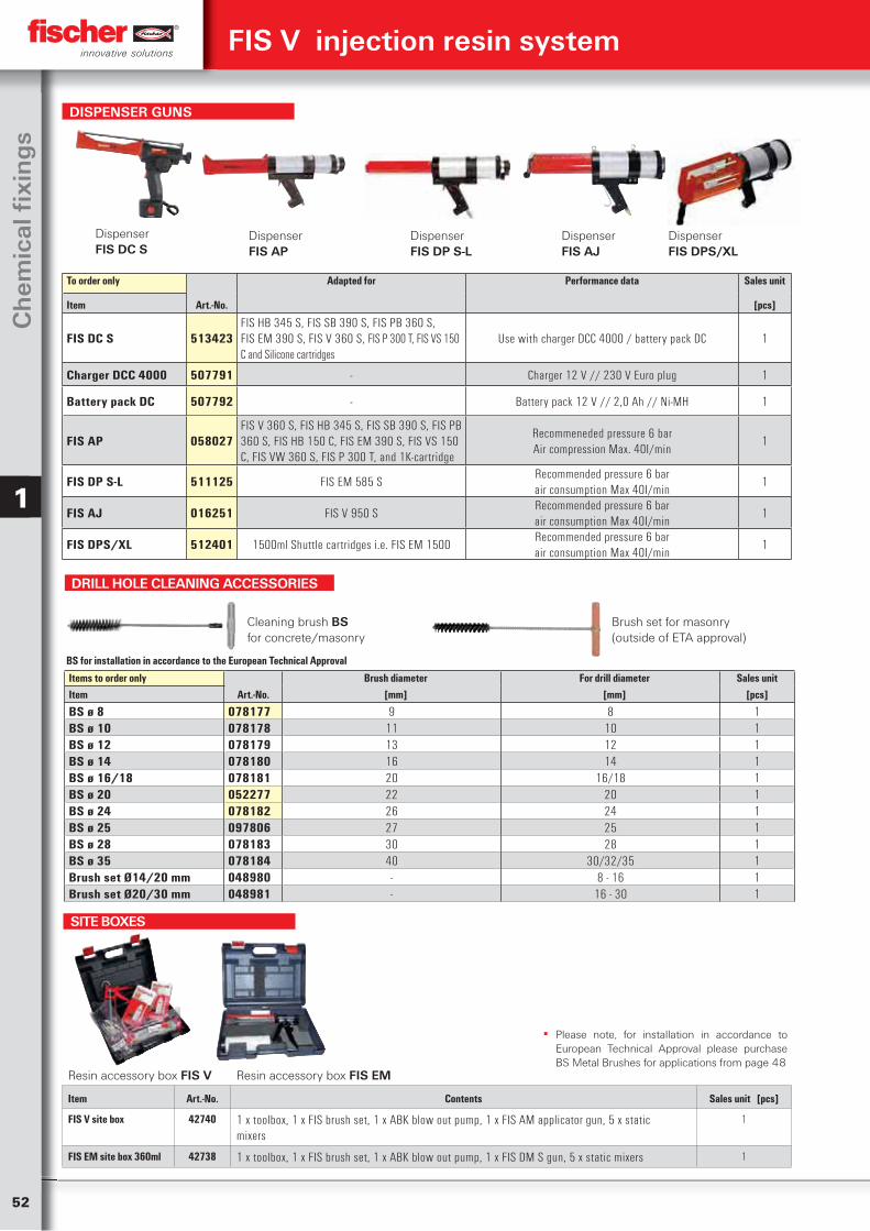
52
Ch
emic
al fi
xin
gs
1
Resin accessory box FIS V Resin accessory box FIS EM
Item Art.-No. Contents Sales unit [pcs]
FIS V site box 42740 1 x toolbox, 1 x FIS brush set, 1 x ABK blow out pump, 1 x FIS AM applicator gun, 5 x static mixers
1
FIS EM site box 360ml 42738 1 x toolbox, 1 x FIS brush set, 1 x ABK blow out pump, 1 x FIS DM S gun, 5 x static mixers 1
SITE BOXES
▪ Please note, for installation in accordance to European Technical Approval please purchase BS Metal Brushes for applications from page 48
FIS V injection resin system
DRILL HOLE CLEANING ACCESSORIES
Cleaning brush BS for concrete/masonry
Brush set for masonry(outside of ETA approval)
Items to order only Brush diameter For drill diameter Sales unitItem Art.-No. [mm] [mm] [pcs]
BS ø 8 078177 9 8 1BS ø 10 078178 11 10 1BS ø 12 078179 13 12 1BS ø 14 078180 16 14 1BS ø 16/18 078181 20 16/18 1BS ø 20 052277 22 20 1BS ø 24 078182 26 24 1BS ø 25 097806 27 25 1BS ø 28 078183 30 28 1BS ø 35 078184 40 30/32/35 1Brush set Ø14/20 mm 048980 - 8 - 16 1Brush set Ø20/30 mm 048981 - 16 - 30 1
BS for installation in accordance to the European Technical Approval
To order only Adapted for Performance data Sales unit
Item Art.-No. [pcs]
FIS DC S 513423FIS HB 345 S, FIS SB 390 S, FIS PB 360 S,FIS EM 390 S, FIS V 360 S, FIS P 300 T, FIS VS 150 C and Silicone cartridges
Use with charger DCC 4000 / battery pack DC 1
Charger DCC 4000 507791 - Charger 12 V // 230 V Euro plug 1
Battery pack DC 507792 - Battery pack 12 V // 2,0 Ah // Ni-MH 1
FIS AP 058027FIS V 360 S, FIS HB 345 S, FIS SB 390 S, FIS PB 360 S, FIS HB 150 C, FIS EM 390 S, FIS VS 150 C, FIS VW 360 S, FIS P 300 T, and 1K-cartridge
Recommeneded pressure 6 barAir compression Max. 40I/min
1
FIS DP S-L 511125 FIS EM 585 SRecommended pressure 6 barair consumption Max 40I/min
1
FIS AJ 016251 FIS V 950 SRecommended pressure 6 barair consumption Max 40I/min
1
FIS DPS/XL 512401 1500ml Shuttle cartridges i.e. FIS EM 1500Recommended pressure 6 barair consumption Max 40I/min
1
Dispenser FIS DC S
DispenserFIS DP S-L
DispenserFIS DPS/XL
Dispenser FIS AP
Dispenser FIS AJ
DISPENSER GUNS
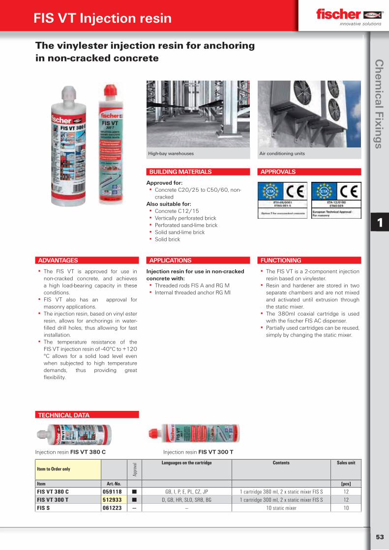
53
Ch
emical Fixin
gs
1
High-bay warehouses Air conditioning units
The vinylester injection resin for anchoring in non-cracked concrete
ADVANTAGES
▪ The FIS VT is approved for use in non-cracked concrete, and achieves a high load-bearing capacity in these conditions.
▪ FIS VT also has an approval for masonry applications.
▪ The injection resin, based on vinyl ester resin, allows for anchorings in water-filled drill holes, thus allowing for fast installation.
▪ The temperature resistance of the FIS VT injection resin of -40°C to +120 °C allows for a solid load level even when subjected to high temperature demands, thus providing great flexibility.
APPLICATIONS
Injection resin for use in non-cracked concrete with:
▪ Threaded rods FIS A and RG M ▪ Internal threaded anchor RG MI
FUNCTIONING
▪ The FIS VT is a 2-component injection resin based on vinylester.
▪ Resin and hardener are stored in two separate chambers and are not mixed and activated until extrusion through the static mixer.
▪ The 380ml coaxial cartridge is used with the fischer FIS AC dispenser.
▪ Partially used cartridges can be reused, simply by changing the static mixer.
BUILDING MATERIALS
Approved for: ▪ Concrete C20/25 to C50/60, non-
crackedAlso suitable for:
▪ Concrete C12/15 ▪ Vertically perforated brick ▪ Perforated sand-lime brick ▪ Solid sand-lime brick ▪ Solid brick
APPROVALS
FIS VT Injection resin
TECHNICAL DATA
Injection resin FIS VT 380 C Injection resin FIS VT 300 T
Item to Order only
Appr
oval Languages on the cartridge Contents Sales unit
Item Art.-No. [pcs]
FIS VT 380 C 059118 ■ GB, I, P, E, PL, CZ, JP 1 cartridge 380 ml, 2 x static mixer FIS S 12FIS VT 300 T 512933 ■ D, GB, HR, SLO, SRB, BG 1 cartridge 300 ml, 2 x static mixer FIS S 12FIS S 061223 — — 10 static mixer 10
54
Ch
emic
al fi
xin
gs
1
FIS VT Injection resin
DRILL HOLE CLEANING ACCESSORIES
Cleaning brush BS for concrete Brush set for masonry
Items to order only Brush diameter For drill diameter Sales unitItem Art.-No. [mm] [mm] [pcs]
BS ø 8 078177 9 8 1BS ø 10 078178 11 10 1BS ø 12 078179 13 12 1BS ø 14 078180 16 14 1BS ø 16/18 078181 20 16/18 1BS ø 20 052277 22 20 1BS ø 24 078182 26 24 1BS ø 25 097806 27 25 1BS ø 28 078183 30 28 1BS ø 35 078184 40 30/32/35 1Brush set Ø14/20 mm 048980 - 8 - 16 1Brush set Ø20/30 mm 048981 - 16 - 30 1
CURING TIME
The above times apply from the moment of contact between resin and hardener in the static mixer.For installation, the cartridge temperature must be at least +5 °C. For longer installation times, i.e. when interruptions occur in work, the mixer should be replaced.
Cartridge temperature Gelling time Temperatureat anchoring base
Curing time
(resin)
‒ 5°C – ± 0°C 24 hrs.± 0°C – + 5°C 3 hrs.
+ 5°C – +10°C 9 Min. + 5°C – +10°C 90 min.+10°C – +20°C 5 Min. +10°C – +20°C 60 min.+20°C – +30°C 4 Min. +20°C – +30°C 45 min.+30°C – +40°C 2 Min. +30°C – +40°C 35 min.
DISPENSER GUNS
To order only Suitable for Sales unitItem Art.-No. [pcs]
FIP Co-Axial Gun 42741 FIS VT 380 C / FIP 700 / FIP 380 C 1KP M2 53117 FIS VS 300 T / FIS V 150 C / FIP 300 SF / FIP 150 SF 1
Dispenser FIP Co-Axial Dispenser KP M2
Compressed-air cleaning gun Blow-out pump ABG
Item to order only Fits Sales unit
Item Art.-No. [pcs]
Compressed-air cleaning gun ABP 059456 FIS A M 16 - M 30 1ABG 089300 - 1
DRILL HOLE CLEANING ACCESSORIES
For the full range of Dispenser Guns please refer to page 39
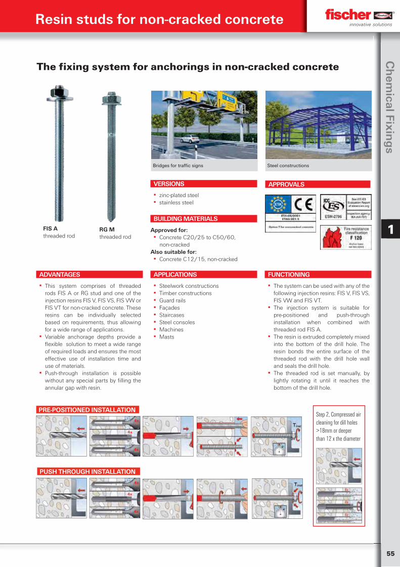
55
Ch
emical Fixin
gs
1
Bridges for traffic signs Steel constructions
The fixing system for anchorings in non-cracked concrete
VERSIONS
▪ zinc-plated steel ▪ stainless steel
APPLICATIONS
▪ Steelwork constructions ▪ Timber constructions ▪ Guard rails ▪ Façades ▪ Staircases ▪ Steel consoles ▪ Machines ▪ Masts
BUILDING MATERIALS
Approved for: ▪ Concrete C20/25 to C50/60,
non-crackedAlso suitable for:
▪ Concrete C12/15, non-cracked
APPROVALS
ADVANTAGES
▪ This system comprises of threaded rods FIS A or RG stud and one of the injection resins FIS V, FIS VS, FIS VW or FIS VT for non-cracked concrete. These resins can be individually selected based on requirements, thus allowing for a wide range of applications.
▪ Variable anchorage depths provide a flexible solution to meet a wide range of required loads and ensures the most effective use of installation time and use of materials.
▪ Push-through installation is possible without any special parts by filling the annular gap with resin.
Resin studs for non-cracked concrete
FIS A threaded rod
RG M threaded rod
FUNCTIONING
▪ The system can be used with any of the following injection resins: FIS V, FIS VS, FIS VW and FIS VT.
▪ The injection system is suitable for pre-positioned and push-through installation when combined with threaded rod FIS A.
▪ The resin is extruded completely mixed into the bottom of the drill hole. The resin bonds the entire surface of the threaded rod with the drill hole wall and seals the drill hole.
▪ The threaded rod is set manually, by lightly rotating it until it reaches the bottom of the drill hole.
PRE-POSITIONED INSTALLATION
4x
4x
4x
PUSH THROUGH INSTALLATION
4x
4x
4x
Step 2, Compressed air cleaning for dill holes >18mm or deeper than 12 x the diameter
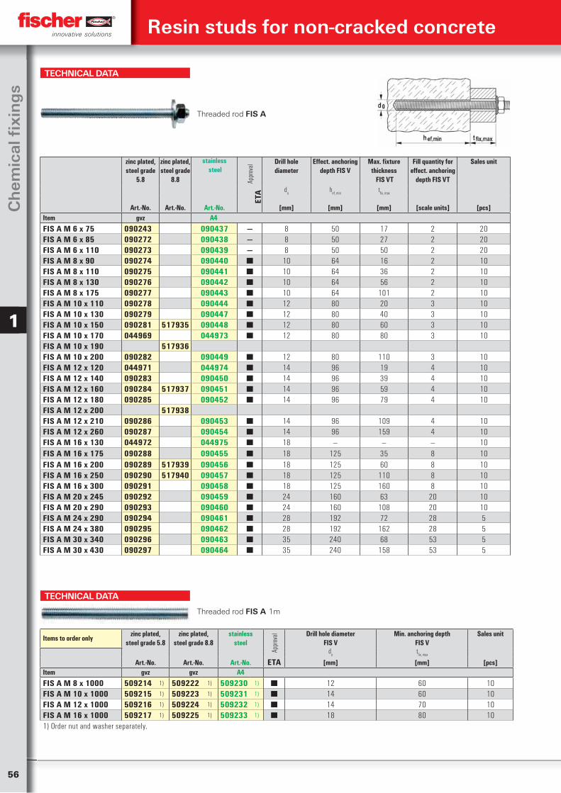
56
Ch
emic
al fi
xin
gs
1
TECHNICAL DATA
Threaded rod FIS A 1m
Items to order onlyzinc plated,
steel grade 5.8zinc plated,
steel grade 8.8stainless
steel
Appr
oval Drill hole diameter
FIS VMin. anchoring depth
FIS VSales unit
do
tfix, max
Art.-No. Art.-No. Art.-No. ETA [mm] [mm] [pcs]Item gvz gvz A4
FIS A M 8 x 1000 509214 1) 509222 1) 509230 1) ■ 12 60 10FIS A M 10 x 1000 509215 1) 509223 1) 509231 1) ■ 14 60 10FIS A M 12 x 1000 509216 1) 509224 1) 509232 1) ■ 14 70 10FIS A M 16 x 1000 509217 1) 509225 1) 509233 1) ■ 18 80 101) Order nut and washer separately.
Resin studs for non-cracked concrete
TECHNICAL DATA
Threaded rod FIS A
zinc plated, steel grade
5.8
zinc plated, steel grade
8.8
stainless steel
Appr
oval
Drill hole diameter
Effect. anchoring depth FIS V
Max. fixture thickness
FIS VT
Fill quantity for effect. anchoring
depth FIS VT
Sales unit
ETA
do
hef, min
tfix, max
Art.-No. Art.-No. Art.-No. [mm] [mm] [mm] [scale units] [pcs]Item gvz A4
FIS A M 6 x 75 090243 090437 — 8 50 17 2 20FIS A M 6 x 85 090272 090438 — 8 50 27 2 20FIS A M 6 x 110 090273 090439 — 8 50 50 2 20FIS A M 8 x 90 090274 090440 ■ 10 64 16 2 10FIS A M 8 x 110 090275 090441 ■ 10 64 36 2 10FIS A M 8 x 130 090276 090442 ■ 10 64 56 2 10FIS A M 8 x 175 090277 090443 ■ 10 64 101 2 10FIS A M 10 x 110 090278 090444 ■ 12 80 20 3 10FIS A M 10 x 130 090279 090447 ■ 12 80 40 3 10FIS A M 10 x 150 090281 517935 090448 ■ 12 80 60 3 10FIS A M 10 x 170 044969 044973 ■ 12 80 80 3 10FIS A M 10 x 190 517936FIS A M 10 x 200 090282 090449 ■ 12 80 110 3 10FIS A M 12 x 120 044971 044974 ■ 14 96 19 4 10FIS A M 12 x 140 090283 090450 ■ 14 96 39 4 10FIS A M 12 x 160 090284 517937 090451 ■ 14 96 59 4 10FIS A M 12 x 180 090285 090452 ■ 14 96 79 4 10FIS A M 12 x 200 517938FIS A M 12 x 210 090286 090453 ■ 14 96 109 4 10FIS A M 12 x 260 090287 090454 ■ 14 96 159 4 10FIS A M 16 x 130 044972 044975 ■ 18 — — — 10FIS A M 16 x 175 090288 090455 ■ 18 125 35 8 10FIS A M 16 x 200 090289 517939 090456 ■ 18 125 60 8 10FIS A M 16 x 250 090290 517940 090457 ■ 18 125 110 8 10FIS A M 16 x 300 090291 090458 ■ 18 125 160 8 10FIS A M 20 x 245 090292 090459 ■ 24 160 63 20 10FIS A M 20 x 290 090293 090460 ■ 24 160 108 20 10FIS A M 24 x 290 090294 090461 ■ 28 192 72 28 5FIS A M 24 x 380 090295 090462 ■ 28 192 162 28 5FIS A M 30 x 340 090296 090463 ■ 35 240 68 53 5FIS A M 30 x 430 090297 090464 ■ 35 240 158 53 5
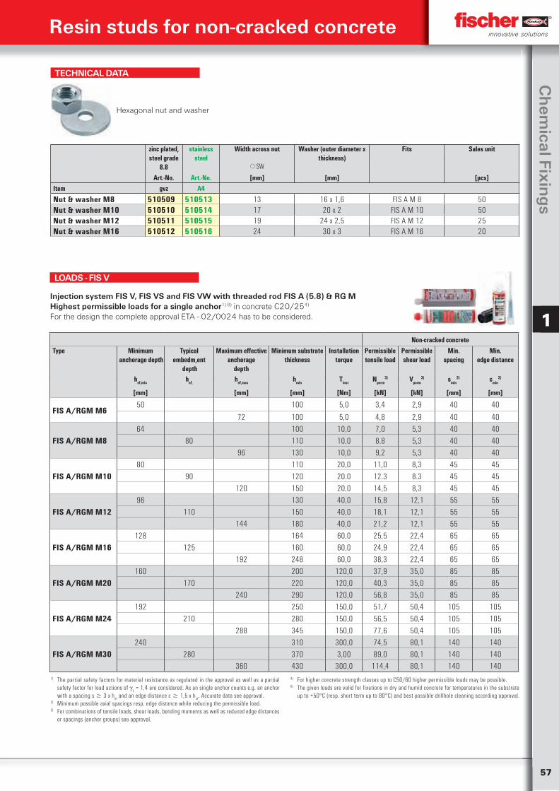
57
Ch
emical Fixin
gs
1
TECHNICAL DATA
Hexagonal nut and washer
zinc plated, steel grade
8.8
stainless steel
Width across nut Washer (outer diameter x thickness)
Fits Sales unit
SW
Art.-No. Art.-No. [mm] [mm] [pcs]Item gvz A4
Nut & washer M8 510509 510513 13 16 x 1,6 FIS A M 8 50Nut & washer M10 510510 510514 17 20 x 2 FIS A M 10 50Nut & washer M12 510511 510515 19 24 x 2,5 FIS A M 12 25Nut & washer M16 510512 510516 24 30 x 3 FIS A M 16 20
Non-cracked concreteType Minimum
anchorage depthTypical
embedm,ent depth
Maximum effectiveanchorage
depth
Minimum substrate thickness
Installation torque
Permissible tensile load
Permissible shear load
Min.spacing
Min.edge distance
hef,min hef, hef,max hmin Tinst Nperm3) Vperm
3) smin2) cmin
2)
[mm] [mm] [mm] [Nm] [kN] [kN] [mm] [mm]
FIS A/RGM M650 100 5,0 3,4 2,9 40 40
72 100 5,0 4,8 2,9 40 40
FIS A/RGM M864 100 10,0 7,0 5,3 40 40
80 110 10,0 8.8 5,3 40 40
96 130 10,0 9,2 5,3 40 40
FIS A/RGM M1080 110 20,0 11,0 8,3 45 45
90 120 20.0 12.3 8.3 45 45
120 150 20,0 14,5 8,3 45 45
FIS A/RGM M1296 130 40,0 15,8 12,1 55 55
110 150 40,0 18,1 12,1 55 55
144 180 40,0 21,2 12,1 55 55
FIS A/RGM M16128 164 60,0 25,5 22,4 65 65
125 160 60,0 24,9 22,4 65 65
192 248 60,0 38,3 22,4 65 65
FIS A/RGM M20160 200 120,0 37,9 35,0 85 85
170 220 120,0 40,3 35,0 85 85
240 290 120,0 56,8 35,0 85 85
FIS A/RGM M24192 250 150,0 51,7 50,4 105 105
210 280 150,0 56,5 50,4 105 105
288 345 150,0 77,6 50,4 105 105
FIS A/RGM M30240 310 300,0 74,5 80,1 140 140
280 370 3,00 89,0 80,1 140 140360 430 300,0 114,4 80,1 140 140
Injection system FIS V, FIS VS and FIS VW with threaded rod FIS A (5.8) & RG MHighest permissible loads for a single anchor1) 6) in concrete C20/254)
For the design the complete approval ETA - 02/0024 has to be considered.
1) The partial safety factors for material resistance as regulated in the approval as well as a partial safety factor for load actions of
L = 1,4 are considered. As an single anchor counts e.g. an anchor
with a spacing s 3 x hef and an edge distance c 1,5 x h
ef. Accurate data see approval.
2) Minimum possible axial spacings resp. edge distance while reducing the permissible load.3) For combinations of tensile loads, shear loads, bending moments as well as reduced edge distances
or spacings (anchor groups) see approval.
4) For higher concrete strength classes up to C50/60 higher permissible loads may be possible.6) The given loads are valid for fixations in dry and humid concrete for temperatures in the substrate
up to +50°C (resp. short term up to 80°C) and best possible drillhole cleaning according approval.
LOADS - FIS V
Resin studs for non-cracked concrete
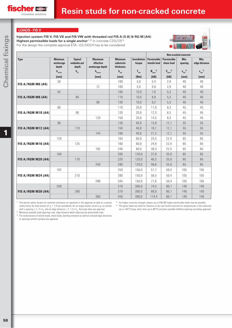
58
Ch
emic
al fi
xin
gs
1
Non-cracked concreteType Minimum
anchorage depth
Typical embedm,ent
depth
Maximum effective
anchorage depth
Minimum substrate thickness
Installation torque
Permissible tensile load
Permissible shear load
Min.spacing
Min.edge distance
hef,min hef, hef,max hmin Tinst Nperm3) Vperm
3) smin2) cmin
2)
[mm] [mm] [mm] [Nm] [kN] [kN] [mm] [mm]
FIS A/RGM M6 (A4)50 100 5,0 3,4 2,9 40 40
72 100 5,0 4,8 2,9 40 40
FIS A/RGM M8 (A4)
64 100 10,0 7,0 5,3 40 40
80 110 10,0 8.8 5,3 40 40
96 130 10,0 9,2 5,3 40 40
FIS A/RGM M10 (A4)
80 110 20,0 11,0 8,3 45 45
90 120 20.0 12.3 8.3 45 45
120 150 20,0 14,5 8,3 45 45
FIS A/RGM M12 (A4)
96 130 40,0 15,8 12,1 55 55
110 150 40,0 18,1 12,1 55 55
144 180 40,0 21,2 12,1 55 55
FIS A/RGM M16 (A4)
128 164 60,0 25,5 22,4 65 65
125 160 60,0 24,9 22,4 65 65
192 248 60,0 38,3 22,4 65 65
FIS A/RGM M20 (A4)
160 200 120,0 37,9 35,0 85 85
170 220 120,0 40,3 35,0 85 85
240 290 120,0 56,8 35,0 85 85
FIS A/RGM M24 (A4)
192 250 150,0 51,7 50,4 105 105
210 280 150,0 56,5 50,4 105 105
288 345 150,0 77,6 50,4 105 105
FIS A/RGM M30 (A4)
240 310 300,0 74,5 80,1 140 140
280 370 300,0 89,0 80,1 140 140
360 430 300,0 114,4 80,1 140 140
Injection system FIS V, FIS VS and FIS VW with threaded rod FIS A (5.8) & RG M (A4) Highest permissible loads for a single anchor1) 6) in concrete C20/254)
For the design the complete approval ETA - 02/0024 has to be considered.
1) The partial safety factors for material resistance as regulated in the approval as well as a partial safety factor for load actions of
L = 1,4 are considered. As an single anchor counts e.g. an anchor
with a spacing s 3 x hef and an edge distance c 1,5 x h
ef. Accurate data see approval.
2) Minimum possible axial spacings resp. edge distance while reducing the permissible load.3) For combinations of tensile loads, shear loads, bending moments as well as reduced edge distances
or spacings (anchor groups) see approval.
4) For higher concrete strength classes up to C50/60 higher permissible loads may be possible.6) The given loads are valid for fixations in dry and humid concrete for temperatures in the substrate
up to +50°C (resp. short term up to 80°C) and best possible drillhole cleaning according approval.
LOADS - FIS V
Resin studs for non-cracked concrete
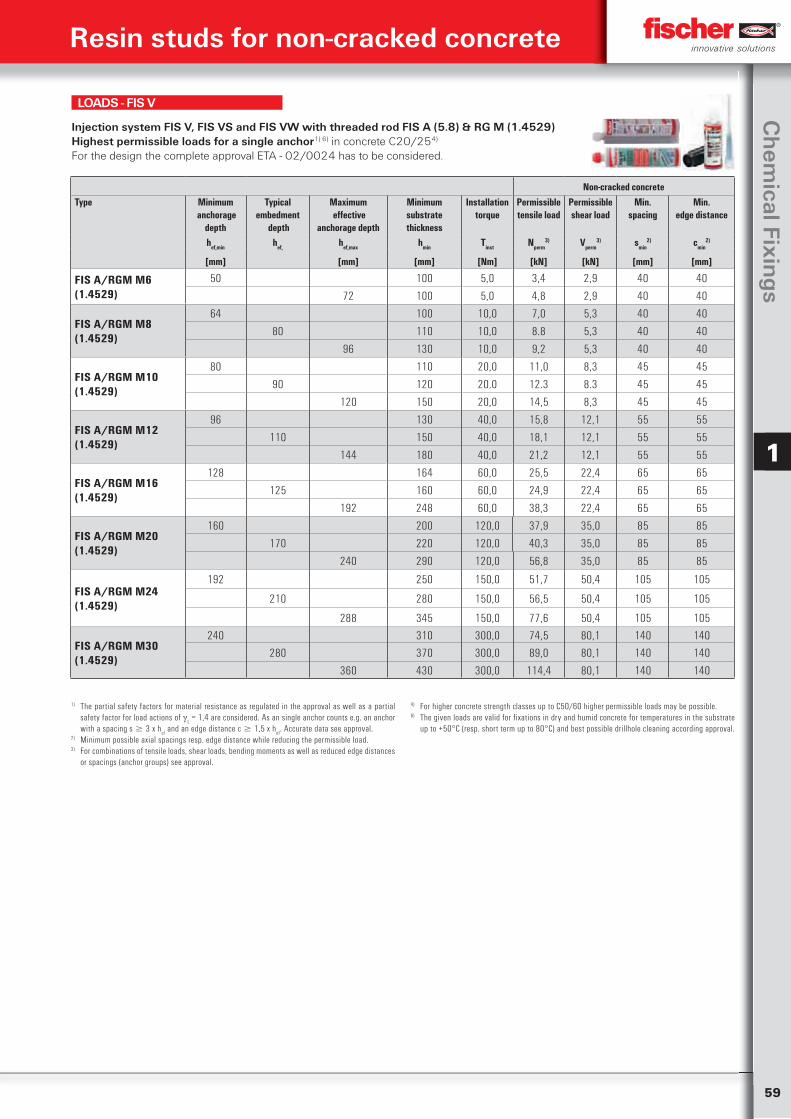
59
Ch
emical Fixin
gs
1
Injection system FIS V, FIS VS and FIS VW with threaded rod FIS A (5.8) & RG M (1.4529) Highest permissible loads for a single anchor1) 6) in concrete C20/254)
For the design the complete approval ETA - 02/0024 has to be considered.
LOADS - FIS V
Non-cracked concreteType Minimum
anchorage depth
Typical embedment
depth
Maximum effective
anchorage depth
Minimum substrate thickness
Installation torque
Permissible tensile load
Permissible shear load
Min.spacing
Min.edge distance
hef,min hef, hef,max hmin Tinst Nperm3) Vperm
3) smin2) cmin
2)
[mm] [mm] [mm] [Nm] [kN] [kN] [mm] [mm]
FIS A/RGM M6 (1.4529)
50 100 5,0 3,4 2,9 40 40
72 100 5,0 4,8 2,9 40 40
FIS A/RGM M8 (1.4529)
64 100 10,0 7,0 5,3 40 40
80 110 10,0 8.8 5,3 40 40
96 130 10,0 9,2 5,3 40 40
FIS A/RGM M10 (1.4529)
80 110 20,0 11,0 8,3 45 45
90 120 20.0 12.3 8.3 45 45
120 150 20,0 14,5 8,3 45 45
FIS A/RGM M12 (1.4529)
96 130 40,0 15,8 12,1 55 55
110 150 40,0 18,1 12,1 55 55
144 180 40,0 21,2 12,1 55 55
FIS A/RGM M16 (1.4529)
128 164 60,0 25,5 22,4 65 65
125 160 60,0 24,9 22,4 65 65
192 248 60,0 38,3 22,4 65 65
FIS A/RGM M20 (1.4529)
160 200 120,0 37,9 35,0 85 85
170 220 120,0 40,3 35,0 85 85
240 290 120,0 56,8 35,0 85 85
FIS A/RGM M24 (1.4529)
192 250 150,0 51,7 50,4 105 105
210 280 150,0 56,5 50,4 105 105
288 345 150,0 77,6 50,4 105 105
FIS A/RGM M30 (1.4529)
240 310 300,0 74,5 80,1 140 140
280 370 300,0 89,0 80,1 140 140
360 430 300,0 114,4 80,1 140 140
Resin studs for non-cracked concrete
1) The partial safety factors for material resistance as regulated in the approval as well as a partial safety factor for load actions of
L = 1,4 are considered. As an single anchor counts e.g. an anchor
with a spacing s 3 x hef and an edge distance c 1,5 x h
ef. Accurate data see approval.
2) Minimum possible axial spacings resp. edge distance while reducing the permissible load.3) For combinations of tensile loads, shear loads, bending moments as well as reduced edge distances
or spacings (anchor groups) see approval.
4) For higher concrete strength classes up to C50/60 higher permissible loads may be possible.6) The given loads are valid for fixations in dry and humid concrete for temperatures in the substrate
up to +50°C (resp. short term up to 80°C) and best possible drillhole cleaning according approval.
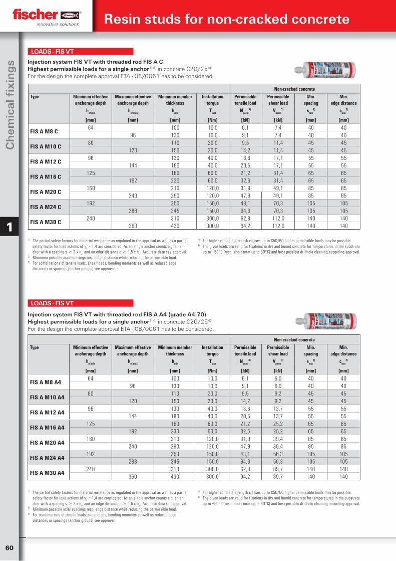
60
Ch
emic
al fi
xin
gs
1
Resin studs for non-cracked concrete
Non-cracked concreteType Minimum effective
anchorage depthMaximum effective
anchorage depthMinimum member
thicknessInstallation
torquePermissible tensile load
Permissible shear load
Min.spacing
Min.edge distance
hef,min hef,max hmin Tinst Nperm3) Vperm
3) smin2) cmin
2)
[mm] [mm] [mm] [Nm] [kN] [kN] [mm] [mm]
FIS A M8 C64 100 10,0 6,1 7,4 40 40
96 130 10,0 9,1 7,4 40 40
FIS A M10 C80 110 20,0 9,5 11,4 45 45
120 150 20,0 14,2 11,4 45 45
FIS A M12 C96 130 40,0 13,6 17,1 55 55
144 180 40,0 20,5 17,1 55 55
FIS A M16 C125 160 60,0 21,2 31,4 65 65
192 230 60,0 32,6 31,4 65 65
FIS A M20 C160 210 120,0 31,9 49,1 85 85
240 290 120,0 47,9 49,1 85 85
FIS A M24 C192 250 150,0 43,1 70,3 105 105
288 345 150,0 64,6 70,3 105 105
FIS A M30 C240 310 300,0 62,8 112,0 140 140
360 430 300,0 94,2 112,0 140 140
Injection system FIS VT with threaded rod FIS A C Highest permissible loads for a single anchor1) 6) in concrete C20/254). For the design the complete approval ETA - 08/0061 has to be considered.
1) The partial safety factors for material resistance as regulated in the approval as well as a partial safety factor for load actions of
L = 1,4 are considered. As an single anchor counts e.g. an an-
chor with a spacing s 3 x hef and an edge distance c 1,5 x h
ef. Accurate data see approval.
2) Minimum possible axial spacings resp. edge distance while reducing the permissible load.3) For combinations of tensile loads, shear loads, bending moments as well as reduced edge
distances or spacings (anchor groups) see approval.
4) For higher concrete strength classes up to C50/60 higher permissible loads may be possible.6) The given loads are valid for fixations in dry and humid concrete for temperatures in the substrate
up to +50°C (resp. short term up to 80°C) and best possible drillhole cleaning according approval.
LOADS - FIS VT
Non-cracked concreteType Minimum effective
anchorage depthMaximum effective
anchorage depthMinimum member
thicknessInstallation
torquePermissible tensile load
Permissible shear load
Min.spacing
Min.edge distance
hef,min hef,max hmin Tinst Nperm3) Vperm
3) smin2) cmin
2)
[mm] [mm] [mm] [Nm] [kN] [kN] [mm] [mm]
FIS A M8 A464 100 10,0 6,1 6,0 40 40
96 130 10,0 9,1 6,0 40 40
FIS A M10 A480 110 20,0 9,5 9,2 45 45
120 150 20,0 14,2 9,2 45 45
FIS A M12 A496 130 40,0 13,6 13,7 55 55
144 180 40,0 20,5 13,7 55 55
FIS A M16 A4125 160 60,0 21,2 25,2 65 65
192 230 60,0 32,6 25,2 65 65
FIS A M20 A4160 210 120,0 31,9 39,4 85 85
240 290 120,0 47,9 39,4 85 85
FIS A M24 A4192 250 150,0 43,1 56,3 105 105
288 345 150,0 64,6 56,3 105 105
FIS A M30 A4240 310 300,0 62,8 89,7 140 140
360 430 300,0 94,2 89,7 140 140
Injection system FIS VT with threaded rod FIS A A4 (grade A4-70)Highest permissible loads for a single anchor1) 6) in concrete C20/254)
For the design the complete approval ETA - 08/0061 has to be considered.
LOADS - FIS VT
1) The partial safety factors for material resistance as regulated in the approval as well as a partial safety factor for load actions of
L = 1,4 are considered. As an single anchor counts e.g. an an-
chor with a spacing s 3 x hef and an edge distance c 1,5 x h
ef. Accurate data see approval.
2) Minimum possible axial spacings resp. edge distance while reducing the permissible load.3) For combinations of tensile loads, shear loads, bending moments as well as reduced edge
distances or spacings (anchor groups) see approval.
4) For higher concrete strength classes up to C50/60 higher permissible loads may be possible.6) The given loads are valid for fixations in dry and humid concrete for temperatures in the substrate
up to +50°C (resp. short term up to 80°C) and best possible drillhole cleaning according approval.
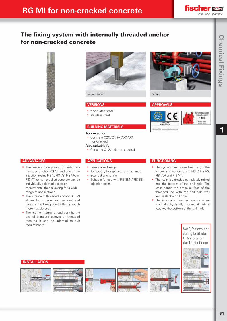
61
Ch
emical Fixin
gs
1
RG MI for non-cracked concrete
Column bases Pumps
The fixing system with internally threaded anchor for non-cracked concrete
ADVANTAGES
▪ The system comprising of internally threaded anchor RG MI and one of the injection resins FIS V, FIS VS, FIS VW or FIS VT for non-cracked concrete can be individually selected based on
requirments, thus allowing for a wide range of applications.
▪ The internally threaded anchor RG MI allows for surface flush removal and reuse of the fixing point, offering much more flexible use.
▪ The metric internal thread permits the use of standard screws or threaded rods so it can be adapted to suit requirements.
VERSIONS
▪ zinc-plated steel ▪ stainless steel
APPLICATIONS
▪ Removable fixings ▪ Temporary fixings, e.g. for machines ▪ Scaffold anchoring ▪ Suitable for use with FIS EM / FIS SB
injection resin.
FUNCTIONING
▪ The system can be used with any of the following injection resins: FIS V, FIS VS, FIS VW and FIS VT.
▪ The resin is extruded completely mixed into the bottom of the drill hole. The resin bonds the entire surface of the threaded rod with the drill hole wall and seals the drill hole.
▪ The internally threaded anchor is set manually, by lightly rotating it until it reaches the bottom of the drill hole.
BUILDING MATERIALS
Approved for: ▪ Concrete C20/25 to C50/60,
non-crackedAlso suitable for:
▪ Concrete C12/15, non-cracked
APPROVALS
INSTALLATION
Step 2, Compressed air cleaning for dill holes >18mm or deeper than 12 x the diameter
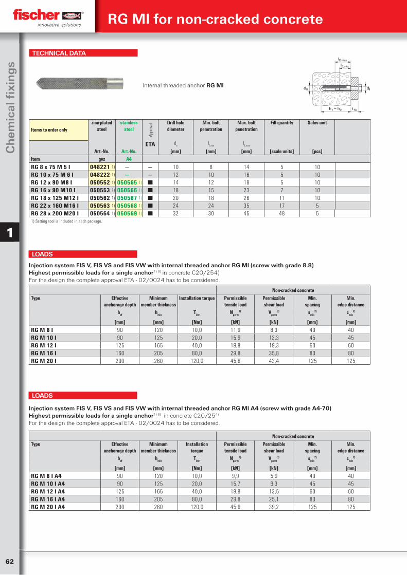
62
Ch
emic
al fi
xin
gs
1
TECHNICAL DATA
Internal threaded anchor RG MI
Items to order onlyzinc-plated
steelstainless
steel
Appr
oval Drill hole
diameterMin. bolt
penetrationMax. bolt
penetrationFill quantity Sales unit
ETA do
lE,min
lE,max
Art.-No. Art.-No. [mm] [mm] [mm] [scale units] [pcs]Item gvz A4
RG 8 x 75 M 5 I 048221 1) — — 10 8 14 5 10RG 10 x 75 M 6 I 048222 1) — — 12 10 16 5 10RG 12 x 90 M8 I 050552 1) 050565 1) ■ 14 12 18 5 10RG 16 x 90 M10 I 050553 1) 050566 1) ■ 18 15 23 7 10RG 18 x 125 M12 I 050562 1) 050567 1) ■ 20 18 26 11 10RG 22 x 160 M16 I 050563 1) 050568 1) ■ 24 24 35 17 5RG 28 x 200 M20 I 050564 1) 050569 1) ■ 32 30 45 48 51) Setting tool is included in each package.
Non-cracked concreteType Effective
anchorage depthMinimum
member thicknessInstallation torque Permissible
tensile loadPermissibleshear load
Min.spacing
Min.edge distance
hef hmin Tinst Nperm3) Vperm
3) smin2) cmin
2)
[mm] [mm] [Nm] [kN] [kN] [mm] [mm]
RG M 8 I 90 120 10,0 11,9 8,3 40 40RG M 10 I 90 125 20,0 15,9 13,3 45 45RG M 12 I 125 165 40,0 19,8 19,3 60 60RG M 16 I 160 205 80,0 29,8 35,8 80 80RG M 20 I 200 260 120,0 45,6 43,4 125 125
Injection system FIS V, FIS VS and FIS VW with internal threaded anchor RG MI (screw with grade 8.8)Highest permissible loads for a single anchor1) 6) in concrete C20/254)For the design the complete approval ETA - 02/0024 has to be considered.
LOADS
Non-cracked concreteType Effective
anchorage depthMinimum
member thicknessInstallation
torquePermissibletensile load
Permissibleshear load
Min.spacing
Min.edge distance
hef hmin Tinst Nperm3) Vperm
3) smin2) cmin
2)
[mm] [mm] [Nm] [kN] [kN] [mm] [mm]
RG M 8 I A4 90 120 10,0 9,9 5,9 40 40RG M 10 I A4 90 125 20,0 15,7 9,3 45 45RG M 12 I A4 125 165 40,0 19,8 13,5 60 60RG M 16 I A4 160 205 80,0 29,8 25,1 80 80RG M 20 I A4 200 260 120,0 45,6 39,2 125 125
Injection system FIS V, FIS VS and FIS VW with internal threaded anchor RG MI A4 (screw with grade A4-70)Highest permissible loads for a single anchor1) 6) in concrete C20/254)
For the design the complete approval ETA - 02/0024 has to be considered.
LOADS
RG MI for non-cracked concrete
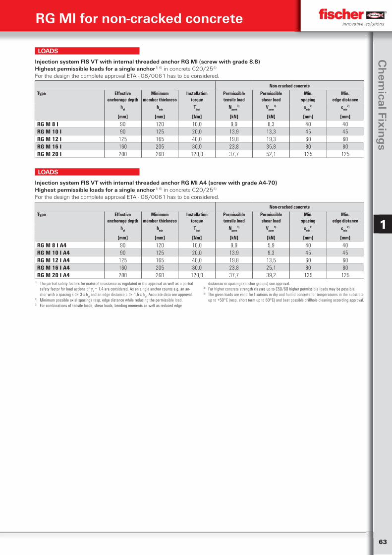
63
Ch
emical Fixin
gs
1
Non-cracked concreteType Effective
anchorage depthMinimum
member thicknessInstallation
torquePermissibletensile load
Permissibleshear load
Min.spacing
Min.edge distance
hef hmin Tinst Nperm3) Vperm
3) smin2) cmin
2)
[mm] [mm] [Nm] [kN] [kN] [mm] [mm]
RG M 8 I A4 90 120 10,0 9,9 5,9 40 40RG M 10 I A4 90 125 20,0 13,9 9,3 45 45RG M 12 I A4 125 165 40,0 19,8 13,5 60 60RG M 16 I A4 160 205 80,0 23,8 25,1 80 80RG M 20 I A4 200 260 120,0 37,7 39,2 125 125
Injection system FIS VT with internal threaded anchor RG MI A4 (screw with grade A4-70)Highest permissible loads for a single anchor1) 6) in concrete C20/254)
For the design the complete approval ETA - 08/0061 has to be considered.
1) The partial safety factors for material resistance as regulated in the approval as well as a partial safety factor for load actions of
L = 1,4 are considered. As an single anchor counts e.g. an an-
chor with a spacing s 3 x hef and an edge distance c 1,5 x h
ef. Accurate data see approval.
2) Minimum possible axial spacings resp. edge distance while reducing the permissible load.3) For combinations of tensile loads, shear loads, bending moments as well as reduced edge
distances or spacings (anchor groups) see approval.4) For higher concrete strength classes up to C50/60 higher permissible loads may be possible.6) The given loads are valid for fixations in dry and humid concrete for temperatures in the substrate
up to +50°C (resp. short term up to 80°C) and best possible drillhole cleaning according approval.
LOADS
Non-cracked concreteType Effective
anchorage depthMinimum
member thicknessInstallation
torquePermissibletensile load
Permissibleshear load
Min.spacing
Min.edge distance
hef hmin Tinst Nperm3) Vperm
3) smin2) cmin
2)
[mm] [mm] [Nm] [kN] [kN] [mm] [mm]
RG M 8 I 90 120 10,0 9,9 8,3 40 40RG M 10 I 90 125 20,0 13,9 13,3 45 45RG M 12 I 125 165 40,0 19,8 19,3 60 60RG M 16 I 160 205 80,0 23,8 35,8 80 80RG M 20 I 200 260 120,0 37,7 52,1 125 125
Injection system FIS VT with internal threaded anchor RG MI (screw with grade 8.8)Highest permissible loads for a single anchor1) 6) in concrete C20/254)
For the design the complete approval ETA - 08/0061 has to be considered.
LOADS
RG MI for non-cracked concrete
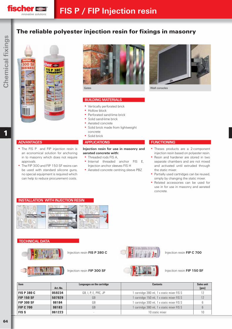
64
Ch
emic
al fi
xin
gs
1
Gates Wall consoles
The reliable polyester injection resin for fixings in masonry
ADVANTAGES
▪ The FIS P and FIP injection resin is an economical solution for anchoring in to masonry which does not require approvals.
▪ The FIP 300 and FIP 150 SF resins can be used with standard silicone guns, no special equipment is required which can help to reduce procurement costs.
APPLICATIONS
Injection resin for use in masonry and aerated concrete with:
▪ Threaded rods FIS A, ▪ Internal threaded anchor FIS E,
Injection anchor sleeves FIS H ▪ Aerated concrete centring sleeve PBZ
FUNCTIONING
▪ Theses products are a 2-component injection resin based on polyester resin.
▪ Resin and hardener are stored in two separate chambers and are not mixed and activated until extruded through the static mixer.
▪ Partially used cartridges can be reused, simply by changing the static mixer.
▪ Related accessories can be used for use in for use in masonry and aerated concrete.
BUILDING MATERIALS
▪ Vertically perforated brick ▪ Hollow block ▪ Perforated sand-lime brick ▪ Solid sand-lime brick ▪ Aerated concrete ▪ Solid brick made from lightweight
concrete ▪ Solid brick
FIS P / FIP Injection resin
TECHNICAL DATA
Injection resin FIS P 380 C Injection resin FIP C 700
Injection resin FIP 300 SF
Item Art.-No.
Languages on the cartridge
Contents
Sales unit[pcs]
FIS P 380 C 059234 GB, I, P, E, PRC, JP 1 cartridge 380 ml, 1 x static mixer FIS S 12FIP 150 SF 507929 GB 1 cartridge 150 ml, 1 x static mixer FIS S 12FIP 300 SF 98184 GB 1 cartridge 300 ml, 1 x static mixer FIS S 6FIP C 700 98183 GB 1 cartridge 380 ml, 1 x static mixer FIS S 6FIS S 061223 - 10 static mixer 10
Injection resin FIP 150 SF
INSTALLATION WITH INJECTION RESIN
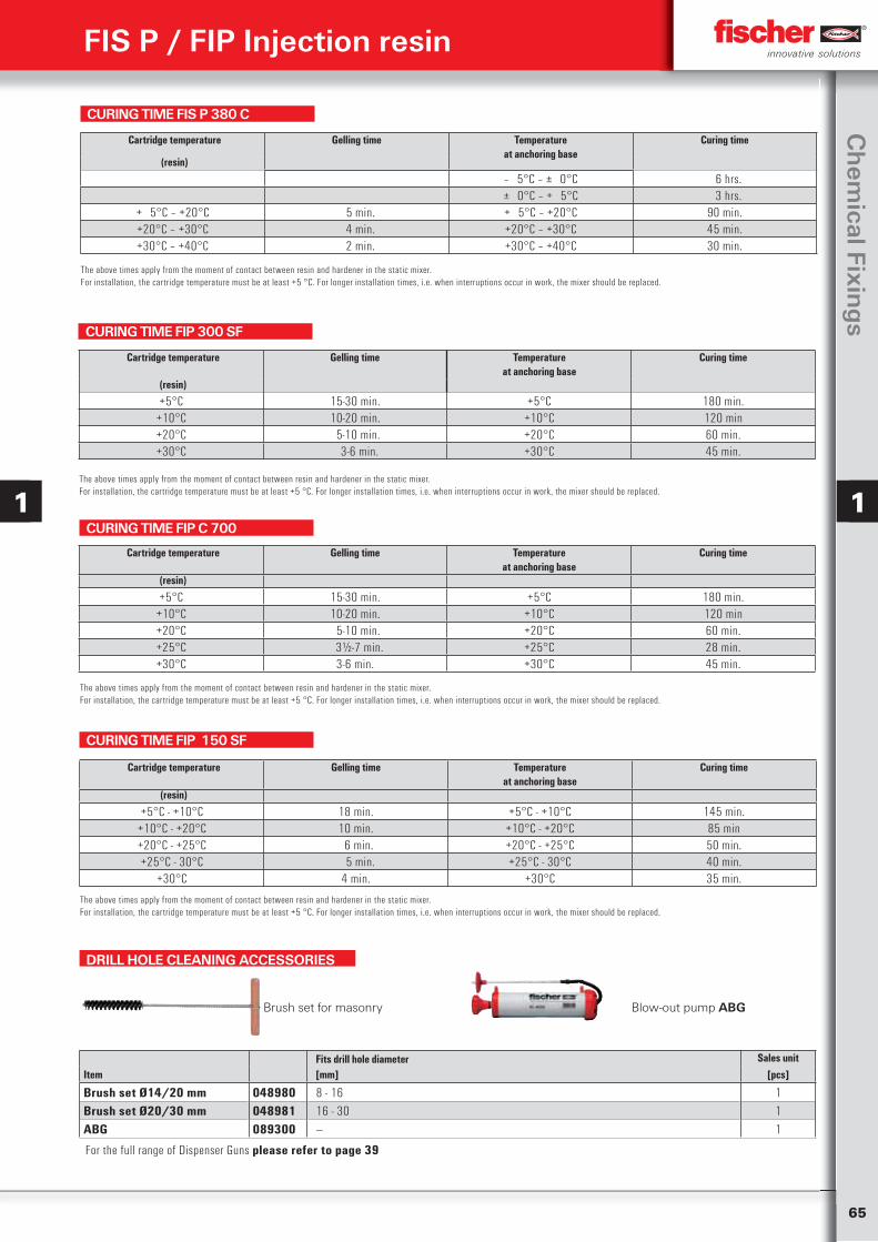
65
Ch
emical Fixin
gs
1 1
CURING TIME FIS P 380 C
The above times apply from the moment of contact between resin and hardener in the static mixer.For installation, the cartridge temperature must be at least +5 °C. For longer installation times, i.e. when interruptions occur in work, the mixer should be replaced.
Cartridge temperature Gelling time Temperatureat anchoring base
Curing time
(resin)
‒ 5°C – ± 0°C 6 hrs.± 0°C – + 5°C 3 hrs.
+ 5°C – +20°C 5 min. + 5°C – +20°C 90 min.+20°C – +30°C 4 min. +20°C – +30°C 45 min.+30°C – +40°C 2 min. +30°C – +40°C 30 min.
CURING TIME FIP 300 SF
The above times apply from the moment of contact between resin and hardener in the static mixer.For installation, the cartridge temperature must be at least +5 °C. For longer installation times, i.e. when interruptions occur in work, the mixer should be replaced.
Cartridge temperature Gelling time Temperatureat anchoring base
Curing time
(resin)
+5°C 15-30 min. +5°C 180 min.+10°C 10-20 min. +10°C 120 min+20°C 5-10 min. +20°C 60 min.+30°C 3-6 min. +30°C 45 min.
CURING TIME FIP C 700
The above times apply from the moment of contact between resin and hardener in the static mixer.For installation, the cartridge temperature must be at least +5 °C. For longer installation times, i.e. when interruptions occur in work, the mixer should be replaced.
Cartridge temperature Gelling time Temperatureat anchoring base
Curing time
(resin)
+5°C 15-30 min. +5°C 180 min.+10°C 10-20 min. +10°C 120 min+20°C 5-10 min. +20°C 60 min.+25°C 3½-7 min. +25°C 28 min.+30°C 3-6 min. +30°C 45 min.
DRILL HOLE CLEANING ACCESSORIES
Brush set for masonry Blow-out pump ABG
Fits drill hole diameter Sales unitItem [mm] [pcs]
Brush set Ø14/20 mm 048980 8 - 16 1Brush set Ø20/30 mm 048981 16 - 30 1ABG 089300 — 1
FIS P / FIP Injection resin
CURING TIME FIP 150 SF
The above times apply from the moment of contact between resin and hardener in the static mixer.For installation, the cartridge temperature must be at least +5 °C. For longer installation times, i.e. when interruptions occur in work, the mixer should be replaced.
Cartridge temperature Gelling time Temperatureat anchoring base
Curing time
(resin)
+5°C - +10°C 18 min. +5°C - +10°C 145 min.+10°C - +20°C 10 min. +10°C - +20°C 85 min+20°C - +25°C 6 min. +20°C - +25°C 50 min.+25°C - 30°C 5 min. +25°C - 30°C 40 min.
+30°C 4 min. +30°C 35 min.
For the full range of Dispenser Guns please refer to page 39
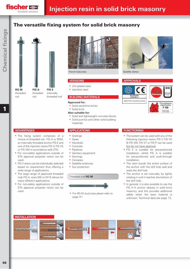
66
Ch
emic
al fi
xin
gs
1
Injection resin in solid brick masonry
French balconies Satellite dishes
The versatile fixing system for solid brick masonry
ADVANTAGES
▪ The fixing system comprises of a choice of threaded rod - FIS A or RGM, an internally threaded anchor FIS E and one of the injection resins FIS V, FIS VS or FIS VW in accordance with ETA.
▪ For non-safety applications outside of ETA approval polyester resins can be used.
▪ FIS V resins can be individually selected based on requirement thus offering a wide range of applications.
▪ The large range of approved threaded rods FIS A, sizes M6 to M16 allows for many different applications.
▪ For non-safety applications outside of ETA approval polyester resins can be used.
VERSIONS
▪ zinc-plated steel ▪ stainless steel
APPLICATIONS
▪ Gratings ▪ Gates ▪ Handrails ▪ Consoles ▪ Pipelines ▪ Sanitary equipment ▪ Awnings ▪ Canopies ▪ Satellite antennas ▪ Sun protection
FUNCTIONING
▪ The system can be used with any of the following injection resins: FIS V, FIS VS & FIS VW. FIS VT or FIS P can be used but do not have approval.
▪ FIS E is suitable for pre-positioned installation, whilst FIS A is suitable for pre-positioned and push-through installation.
▪ The resin bonds the entire surface of the anchor with the drill hole wall and seals the drill hole.
▪ The anchor is set manually, by lightly rotating it until it reaches the bottom of the drill hole. .
▪ In general, it is also possible to use the FIS H K anchor sleeves in solid brick masonry, and this provides additional safety when the base material is unknown. Technical data see page 72.
BUILDING MATERIALS
Approved for: ▪ Solid sand-lime bricks ▪ Solid brick
Also suitable for: ▪ Solid and lightweight concrete blocks ▪ Solid pumice and other solid building
materials
APPROVALS
INSTALLATION
RG M threaded rod
FIS Athreaded rod
FIS Einternally threaded rod
▪ For RG M stud sizes pleser refer to page 41
Threaded rod RG M
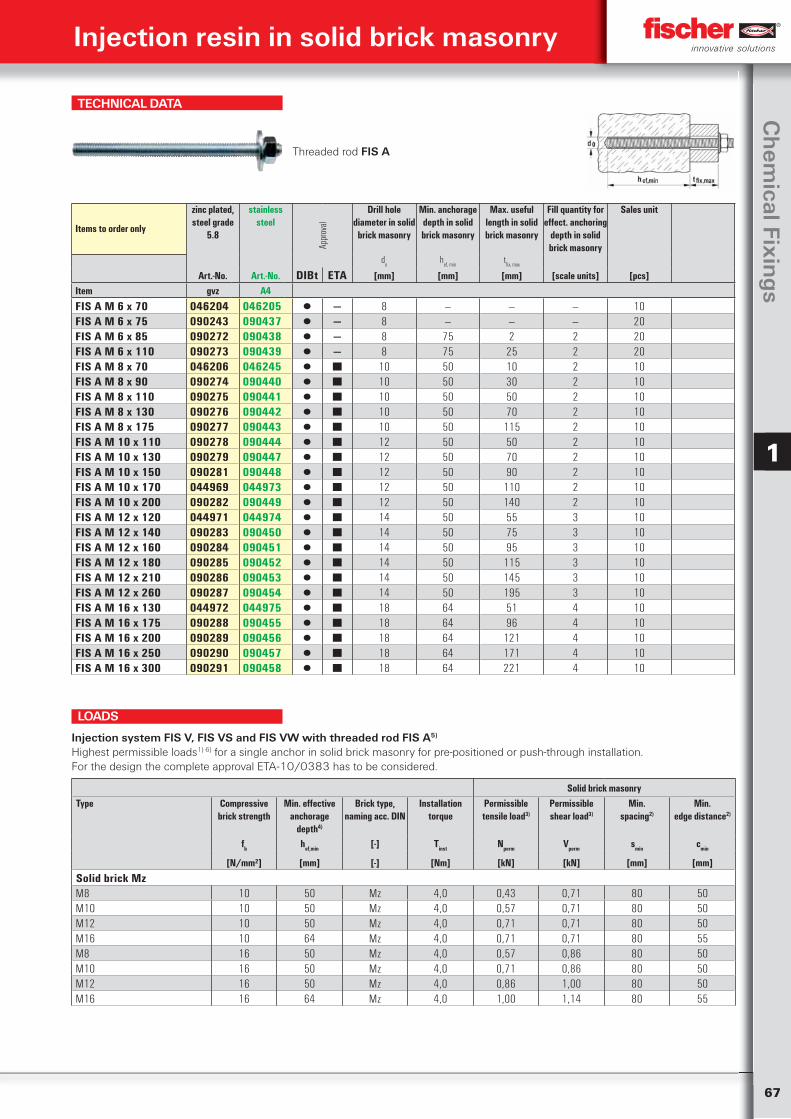
67
Ch
emical Fixin
gs
1
TECHNICAL DATA
Threaded rod FIS A
Items to order only
zinc plated, steel grade
5.8
stainless steel
Appr
oval
Drill hole diameter in solid
brick masonry
Min. anchorage depth in solid brick masonry
Max. useful length in solid brick masonry
Fill quantity for effect. anchoring
depth in solid brick masonry
Sales unit
do
hef, min
tfix, max
Art.-No. Art.-No. DIBt ETA [mm] [mm] [mm] [scale units] [pcs]Item gvz A4
FIS A M 6 x 70 046204 046205 ▯ — 8 — — — 10FIS A M 6 x 75 090243 090437 ▯ — 8 — — — 20FIS A M 6 x 85 090272 090438 ▯ — 8 75 2 2 20FIS A M 6 x 110 090273 090439 ▯ — 8 75 25 2 20FIS A M 8 x 70 046206 046245 ▯ ■ 10 50 10 2 10FIS A M 8 x 90 090274 090440 ▯ ■ 10 50 30 2 10FIS A M 8 x 110 090275 090441 ▯ ■ 10 50 50 2 10FIS A M 8 x 130 090276 090442 ▯ ■ 10 50 70 2 10FIS A M 8 x 175 090277 090443 ▯ ■ 10 50 115 2 10FIS A M 10 x 110 090278 090444 ▯ ■ 12 50 50 2 10FIS A M 10 x 130 090279 090447 ▯ ■ 12 50 70 2 10FIS A M 10 x 150 090281 090448 ▯ ■ 12 50 90 2 10FIS A M 10 x 170 044969 044973 ▯ ■ 12 50 110 2 10FIS A M 10 x 200 090282 090449 ▯ ■ 12 50 140 2 10FIS A M 12 x 120 044971 044974 ▯ ■ 14 50 55 3 10FIS A M 12 x 140 090283 090450 ▯ ■ 14 50 75 3 10FIS A M 12 x 160 090284 090451 ▯ ■ 14 50 95 3 10FIS A M 12 x 180 090285 090452 ▯ ■ 14 50 115 3 10FIS A M 12 x 210 090286 090453 ▯ ■ 14 50 145 3 10FIS A M 12 x 260 090287 090454 ▯ ■ 14 50 195 3 10FIS A M 16 x 130 044972 044975 ▯ ■ 18 64 51 4 10FIS A M 16 x 175 090288 090455 ▯ ■ 18 64 96 4 10FIS A M 16 x 200 090289 090456 ▯ ■ 18 64 121 4 10FIS A M 16 x 250 090290 090457 ▯ ■ 18 64 171 4 10FIS A M 16 x 300 090291 090458 ▯ ■ 18 64 221 4 10
Solid brick masonryType Compressive
brick strengthMin. effective
anchorage depth4)
Brick type, naming acc. DIN
Installation torque
Permissible tensile load3)
Permissible shear load3)
Min.spacing2)
Min.edge distance2)
fb hef,min [-] Tinst Nperm Vperm smin cmin
[N/mm²] [mm] [-] [Nm] [kN] [kN] [mm] [mm]
Solid brick MzM8 10 50 Mz 4,0 0,43 0,71 80 50M10 10 50 Mz 4,0 0,57 0,71 80 50M12 10 50 Mz 4,0 0,71 0,71 80 50M16 10 64 Mz 4,0 0,71 0,71 80 55M8 16 50 Mz 4,0 0,57 0,86 80 50M10 16 50 Mz 4,0 0,71 0,86 80 50M12 16 50 Mz 4,0 0,86 1,00 80 50M16 16 64 Mz 4,0 1,00 1,14 80 55
Injection system FIS V, FIS VS and FIS VW with threaded rod FIS A5)
Highest permissible loads1) 6) for a single anchor in solid brick masonry for pre-positioned or push-through installation.For the design the complete approval ETA-10/0383 has to be considered.
LOADS
Injection resin in solid brick masonry
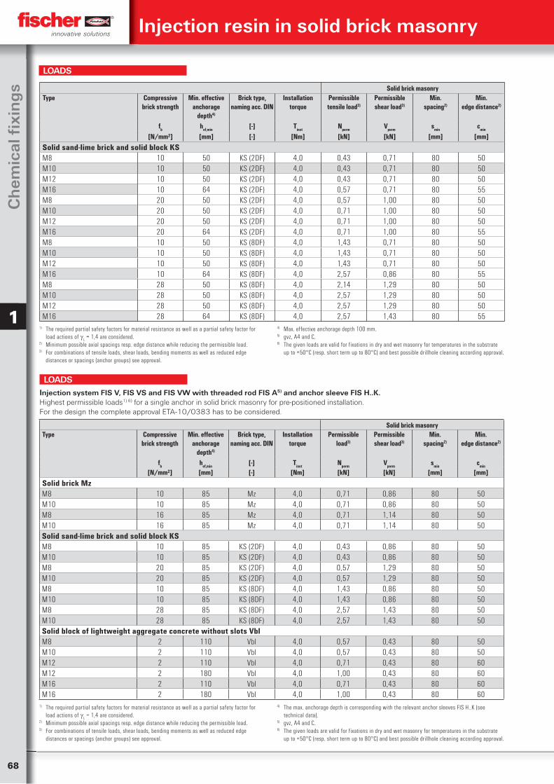
68
Ch
emic
al fi
xin
gs
1
Solid brick masonryType Compressive
brick strengthMin. effective
anchorage depth4)
Brick type, naming acc. DIN
Installation torque
Permissible tensile load3)
Permissible shear load3)
Min.spacing2)
Min.edge distance2)
fb hef,min [-] Tinst Nperm Vperm smin cmin
[N/mm²] [mm] [-] [Nm] [kN] [kN] [mm] [mm]
Solid sand-lime brick and solid block KSM8 10 50 KS (2DF) 4,0 0,43 0,71 80 50M10 10 50 KS (2DF) 4,0 0,43 0,71 80 50M12 10 50 KS (2DF) 4,0 0,43 0,71 80 50M16 10 64 KS (2DF) 4,0 0,57 0,71 80 55M8 20 50 KS (2DF) 4,0 0,57 1,00 80 50M10 20 50 KS (2DF) 4,0 0,71 1,00 80 50M12 20 50 KS (2DF) 4,0 0,71 1,00 80 50M16 20 64 KS (2DF) 4,0 0,71 1,00 80 55M8 10 50 KS (8DF) 4,0 1,43 0,71 80 50M10 10 50 KS (8DF) 4,0 1,43 0,71 80 50M12 10 50 KS (8DF) 4,0 1,43 0,71 80 50M16 10 64 KS (8DF) 4,0 2,57 0,86 80 55M8 28 50 KS (8DF) 4,0 2,14 1,29 80 50M10 28 50 KS (8DF) 4,0 2,57 1,29 80 50M12 28 50 KS (8DF) 4,0 2,57 1,29 80 50M16 28 64 KS (8DF) 4,0 2,57 1,43 80 55
1) The required partial safety factors for material resistance as well as a partial safety factor for load actions of
L = 1,4 are considered.
2) Minimum possible axial spacings resp. edge distance while reducing the permissible load.3) For combinations of tensile loads, shear loads, bending moments as well as reduced edge
distances or spacings (anchor groups) see approval.
4) Max. effective anchorage depth 100 mm.5) gvz, A4 and C.6) The given loads are valid for fixations in dry and wet masonry for temperatures in the substrate
up to +50°C (resp. short term up to 80°C) and best possible drillhole cleaning according approval.
LOADS
Solid brick masonryType Compressive
brick strengthMin. effective
anchorage depth4)
Brick type, naming acc. DIN
Installation torque
Permissible load3)
Permissible shear load3)
Min.spacing2)
Min.edge distance2)
fb hef,min [-] Tinst Nperm Vperm smin cmin
[N/mm²] [mm] [-] [Nm] [kN] [kN] [mm] [mm]
Solid brick MzM8 10 85 Mz 4,0 0,71 0,86 80 50M10 10 85 Mz 4,0 0,71 0,86 80 50M8 16 85 Mz 4,0 0,71 1,14 80 50M10 16 85 Mz 4,0 0,71 1,14 80 50Solid sand-lime brick and solid block KSM8 10 85 KS (2DF) 4,0 0,43 0,86 80 50M10 10 85 KS (2DF) 4,0 0,43 0,86 80 50M8 20 85 KS (2DF) 4,0 0,57 1,29 80 50M10 20 85 KS (2DF) 4,0 0,57 1,29 80 50M8 10 85 KS (8DF) 4,0 1,43 0,86 80 50M10 10 85 KS (8DF) 4,0 1,43 0,86 80 50M8 28 85 KS (8DF) 4,0 2,57 1,43 80 50M10 28 85 KS (8DF) 4,0 2,57 1,43 80 50Solid block of lightweight aggregate concrete without slots VblM8 2 110 Vbl 4,0 0,57 0,43 80 50M10 2 110 Vbl 4,0 0,57 0,43 80 50M12 2 110 Vbl 4,0 0,71 0,43 80 60M12 2 180 Vbl 4,0 1,00 0,43 80 60M16 2 110 Vbl 4,0 0,71 0,43 80 60M16 2 180 Vbl 4,0 1,00 0,43 80 60
Injection system FIS V, FIS VS and FIS VW with threaded rod FIS A5) and anchor sleeve FIS H..K.Highest permissible loads1) 6) for a single anchor in solid brick masonry for pre-positioned installation.For the design the complete approval ETA-10/0383 has to be considered.
1) The required partial safety factors for material resistance as well as a partial safety factor for load actions of
L = 1,4 are considered.
2) Minimum possible axial spacings resp. edge distance while reducing the permissible load.3) For combinations of tensile loads, shear loads, bending moments as well as reduced edge
distances or spacings (anchor groups) see approval.
4) The max. anchorage depth is corresponding with the relevant anchor sleeves FIS H..K (see technical data).
5) gvz, A4 and C.6) The given loads are valid for fixations in dry and wet masonry for temperatures in the substrate
up to +50°C (resp. short term up to 80°C) and best possible drillhole cleaning according approval.
LOADS
Injection resin in solid brick masonry
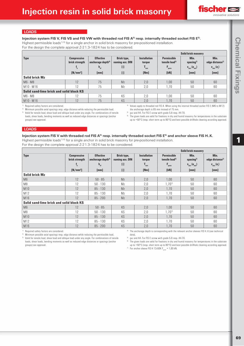
69
Ch
emical Fixin
gs
1
Solid brick masonryType Compressive
brick strengthEffective
anchorage depth4)
Brick type,naming acc. DIN
Installationtorque
Permissibletensile load3)
Min.spacing2)
Min.edge distance2)
fb hef [-] Tinst Fperm smin (amin) cmin (ar)
[N/mm²] [mm] [-] [Nm] [kN] [mm] [mm]
Solid brick MzM6 - M8 12 75 Mz 2,0 1,00 50 60M10 - M16 12 75 Mz 2,0 1,70 50 60Solid sand-lime brick and solid block KSM6 - M8 12 75 KS 2,0 1,00 50 60M10 - M16 12 75 KS 2,0 1,70 50 60
Injection system FIS V, FIS VS and FIS VW with threaded rod FIS A5) resp. internally threaded socket FIS E5).Highest permissible loads1) 6) for a single anchor in solid brick masonry for pre-positioned installation.For the design the complete approval Z-21.3-1824 has to be considered.
1) Required safety factors are considered.2) Minimum possible axial spacings resp. edge distance while reducing the permissible load.3) Valid for tensile load, shear load and oblique load under any angle. For combinations of tensile
loads, shear loads, bending moments as well as reduced edge distances or spacings (anchor groups) see approval.
4) Values apply to threaded rod FIS A. When using the internal threaded socket FIS E (M6 to M12) the anchorage depth is 85 mm instead of 75 mm.
5) gvz and A4. For FIS E screw with grade 5.8 resp. A4-70.6) The given loads are valid for fixations in dry and humid masonry for temperatures in the substrate
up to +50°C (resp. short term up to 80°C) and best possible drillhole cleaning according approval.
LOADS
Solid brick masonryType Compressive
brick strengthEffective
anchorage depth4)
Brick type,naming acc. DIN
Installationtorque
Permissibletensile load3)
Min.spacing2)
Min.edge distance2)
fb hef [-] Tinst Fperm smin (amin) cmin (ar)
[N/mm²] [mm] [-] [Nm] [kN] [mm] [mm]
Solid brick MzM6 12 50 - 85 Mz 2,0 1,00 50 60M8 12 50 - 130 Mz 2,0 1,707) 50 60M10 12 85 - 130 Mz 2,0 1,70 50 60M12 12 85 - 130 Mz 2,0 1,70 50 60M16 12 85 - 200 Mz 2,0 1,70 50 60Solid sand-lime brick and solid block KSM6 12 50 - 85 KS 2,0 1,00 50 60M8 12 50 - 130 KS 2,0 1,707) 50 60M10 12 85 - 130 KS 2,0 1,70 50 60M12 12 85 - 130 KS 2,0 1,70 50 60M16 12 85 - 200 KS 2,0 1,70 50 60
Injection system FIS V with threaded rod FIS A5) resp. internally threaded socket FIS E5) and anchor sleeve FIS H..K.Highest permissible loads1) 6) for a single anchor in solid brick masonry for pre-positioned installation.For the design the complete approval Z-21.3-1824 has to be considered.
1) Required safety factors are considered.2) Minimum possible axial spacings resp. edge distance while reducing the permissible load.3) Valid for tensile load, shear load and oblique load under any angle. For combinations of tensile
loads, shear loads, bending moments as well as reduced edge distances or spacings (anchor groups) see approval.
4) The anchorage depth is corresponding with the relevant anchor sleeves FIS H..K (see technical data).
5) gvz and A4. For FIS E screw with grade 5.8 resp. A4-70.6) The given loads are valid for fixations in dry and humid masonry for temperatures in the substrate
up to +50°C (resp. short term up to 80°C) and best possible drillhole cleaning according approval.7) For anchor sleeve FIS H 12x50K F
perm = 1,00 kN.
LOADS
Injection resin in solid brick masonry
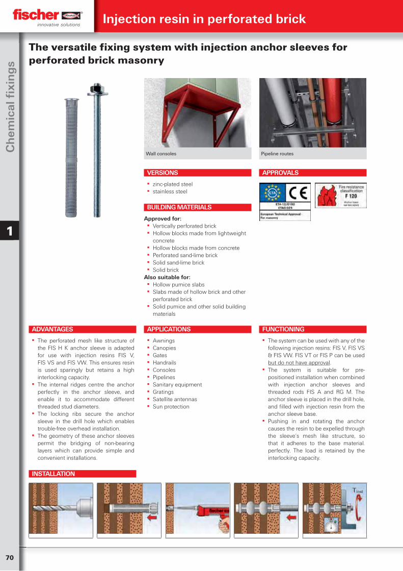
70
Ch
emic
al fi
xin
gs
1
Wall consoles Pipeline routes
The versatile fixing system with injection anchor sleeves for perforated brick masonry
ADVANTAGES
▪ The perforated mesh like structure of the FIS H K anchor sleeve is adapted for use with injection resins FIS V, FIS VS and FIS VW. This ensures resin is used sparingly but retains a high interlocking capacity.
▪ The internal ridges centre the anchor perfectly in the anchor sleeve, and enable it to accommodate different threaded stud diameters.
▪ The locking ribs secure the anchor sleeve in the drill hole which enables trouble-free overhead installation.
▪ The geometry of these anchor sleeves permit the bridging of non-bearing layers which can provide simple and convenient installations.
VERSIONS
▪ zinc-plated steel ▪ stainless steel
APPLICATIONS
▪ Awnings ▪ Canopies ▪ Gates ▪ Handrails ▪ Consoles ▪ Pipelines ▪ Sanitary equipment ▪ Gratings ▪ Satellite antennas ▪ Sun protection
FUNCTIONING
▪ The system can be used with any of the following injection resins: FIS V, FIS VS & FIS VW. FIS VT or FIS P can be used but do not have approval.
▪ The system is suitable for pre-positioned installation when combined with injection anchor sleeves and threaded rods FIS A and RG M. The anchor sleeve is placed in the drill hole, and filled with injection resin from the anchor sleeve base.
▪ Pushing in and rotating the anchor causes the resin to be expelled through the sleeve‘s mesh like structure, so that it adheres to the base material. perfectly. The load is retained by the interlocking capacity.
BUILDING MATERIALS
Approved for: ▪ Vertically perforated brick ▪ Hollow blocks made from lightweight
concrete ▪ Hollow blocks made from concrete ▪ Perforated sand-lime brick ▪ Solid sand-lime brick ▪ Solid brick
Also suitable for: ▪ Hollow pumice slabs ▪ Slabs made of hollow brick and other
perforated brick ▪ Solid pumice and other solid building
materials
APPROVALS
Injection resin in perforated brick
INSTALLATION
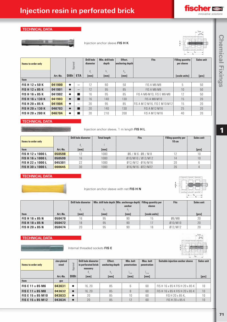
71
Ch
emical Fixin
gs
1 TECHNICAL DATA
Injection anchor sleeve, 1 m length FIS H L
Items to order onlyDrill hole diameter Total length Fits Filling quantity per
10 cmSales unit
do
l
Item Art.-No. [mm] [mm] [pcs]
FIS H 12 x 1000 L 050598 12 1000 Ø6 / M 6 - Ø8 / M 8 12 10FIS H 16 x 1000 L 050599 16 1000 Ø10/M10 / Ø12/M12 14 10FIS H 22 x 1000 L 045301 22 1000 Ø12/M12 - Ø16/M16 20 6FIS H 30 x 1000 L 000645 30 1000 Ø16/M16 - Ø22/M22 26 4
TECHNICAL DATA
Injection anchor sleeve FIS H K
Items to order only
Appr
oval
Drill hole diameter
Min. drill hole depth
Effect. anchoring depth
Fits Filling quantity per sleeve
Sales unit
do
h1
hef
Art.-No. DIBt ETA [mm] [mm] [mm] [scale units] [pcs]Item
FIS H 12 x 50 K 041900 ▯ — 12 60 50 FIS A M6-M8 5 50FIS H 12 x 85 K 041901 ▯ — 12 95 85 FIS A M6-M8 10 50FIS H 16 x 85 K 041902 ▯ ■ 16 95 85 FIS A M8-M10, FIS E M6-M8 12 50FIS H 16 x 130 K 041903 ▯ ■ 16 140 130 FIS A M8-M10 15 20FIS H 20 x 85 K 041904 ▯ — 20 95 85 FIS A M12-M16, FIS E M10-M12 15 20FIS H 20 x 130 K 046703 ▯ ■ 20 140 130 FIS A M12-M16 25 20FIS H 20 x 200 K 046704 ▯ ■ 20 210 200 FIS A M12-M16 40 20
TECHNICAL DATA
Injection anchor sleeve with net FIS H N
Drill hole diameter Min. drill hole depth Min. anchorage depth anchor
Filling quantity per sleeve
Fits Sales unit
do
h1
hv
Item Art.-No. [mm] [mm] [mm] [scale units] [pcs]
FIS H 16 x 85 N 050470 16 95 90 15 Ø8/M8 20FIS H 18 x 85 N 050472 18 95 90 17 Ø10/M10 20FIS H 20 x 85 N 050474 20 95 90 18 Ø12/M12 20
TECHNICAL DATA
Internal threaded sockets FIS E
Items to order onlyzinc-plated
steel
Appr
oval
Drill hole diameter in perforated brick
masonry
Effect. anchoring depth
Min. bolt penetration
Max. bolt penetration
Suitable injection anchor sleeve Sales unit
do
hef
lE,min
lE,max
Art.-No. DIBt [mm] [mm] [mm] [mm] [pcs]Item gvz
FIS E 11 x 85 M6 043631 ▯ 16, 20 85 6 60 FIS H 16 x 85 K FIS H 20 x 85 K 10
FIS E 11 x 85 M8 043632 ▯ 16, 20 85 8 60 FIS H 16 x 85 K FIS H 20 x 85 K 10FIS E 15 x 85 M10 043633 ▯ 20 85 10 60 FIS H 20 x 85 K, 10FIS E 15 x 85 M12 043634 ▯ 20 85 12 60 FIS H 20 x 85 K 10
Injection resin in perforated brick
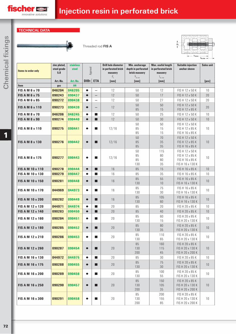
72
Ch
emic
al fi
xin
gs
1
TECHNICAL DATA
Threaded rod FIS A
Items to order only
zinc plated, steel grade
5.8
stainless steel
Appr
oval
Drill hole diameter in perforated brick
masonry
Min. anchorage depth in perforated
brick masonry
Max. useful length in perforated brick
masonry
Suitable injection anchor sleeve
Sales unit
do
hef, min
tfix, max
Art.-No. Art.-No. DIBt ETA [mm] [mm] [mm] [pcs]Item gvz A4
FIS A M 6 x 70 046204 046205 ▯ — 12 50 12 FIS H 12 x 50 K 10FIS A M 6 x 75 090243 090437 ▯ — 12 50 17 FIS H 12 x 50 K 20FIS A M 6 x 85 090272 090438 ▯ — 12 50 27 FIS H 12 x 50 K 20
FIS A M 6 x 110 090273 090439 ▯ — 1250 85
50 15
FIS H 12 x 50 K FIS H 12 x 85 K
20
FIS A M 8 x 70 046206 046245 ▯ ■ 12 50 25 FIS H 12 x 50 K 10FIS A M 8 x 90 090274 090440 ▯ ■ 12 50 30 FIS H 12 x 50 K 10
FIS A M 8 x 110 090275 090441 ▯ ■ 12/1650 85 85
50 15 15
FIS H 12 x 50 K FIS H 12 x 85 K FIS H 16 x 85 K
10
FIS A M 8 x 130 090276 090442 ▯ ■ 12/1650 85 85
70 35 35
FIS H 12 x 50 K FIS H 12 x 85 K FIS H 16 x 85 K
10
FIS A M 8 x 175 090277 090443 ▯ ■ 12/16
50 85 85
130
115 80 80 35
FIS H 12 x 50 K FIS H 12 x 85 K FIS H 16 x 85 K
FIS H 16 x 130 K
10
FIS A M 10 x 110 090278 090444 ▯ ■ 16 85 15 FIS H 16 x 85 K 10FIS A M 10 x 130 090279 090447 ▯ ■ 16 85 35 FIS H 16 x 85 K 10
FIS A M 10 x 150 090281 090448 ▯ ■ 1685
13055 10
FIS H 16 x 85 K FIS H 16 x 130 K
10
FIS A M 10 x 170 044969 044973 ▯ ■ 1685
13075 30
FIS H 16 x 85 K FIS H 16 x 130 K
10
FIS A M 10 x 200 090282 090449 ▯ ■ 1685
130105 60
FIS H 16 x 85 K FIS H 16 x 130 K
10
FIS A M 12 x 120 044971 044974 ▯ ■ 20 85 20 FIS H 20 x 85 K 10FIS A M 12 x 140 090283 090450 ▯ ■ 20 85 40 FIS H 20 x 85 K 10
FIS A M 12 x 160 090284 090451 ▯ ■ 2085
13060 15
FIS H 20 x 85 K FIS H 20 x 130 K
10
FIS A M 12 x 180 090285 090452 ▯ ■ 2085
13080 35
FIS H 20 x 85 K FIS H 20 x 130 K
10
FIS A M 12 x 210 090286 090453 ▯ ■ 2085
130110 65
FIS H 20 x 85 K FIS H 20 x 130 K
10
FIS A M 12 x 260 090287 090454 ▯ ■ 2085
130 200
160 115 45
FIS H 20 x 85 K FIS H 20 x 130 K FIS H 20 x 200 K
10
FIS A M 16 x 130 044972 044975 ▯ ■ 20 85 30 FIS H 20 x 85 K 10
FIS A M 16 x 175 090288 090455 ▯ ■ 2085
13075 30
FIS H 20 x 85 K FIS H 20 x 130 K
10
FIS A M 16 x 200 090289 090456 ▯ ■ 2085
130100 55
FIS H 20 x 85 K FIS H 20 x 130 K
10
FIS A M 16 x 250 090290 090457 ▯ ■ 2085
130 200
150 105 35
FIS H 20 x 85 K FIS H 20 x 130 K FIS H 20 x 200 K
10
FIS A M 16 x 300 090291 090458 ▯ ■ 2085
130 200
200 155 85
FIS H 20 x 85 K FIS H 20 x 130 K FIS H 20 x 200 K
10
Injection resin in perforated brick
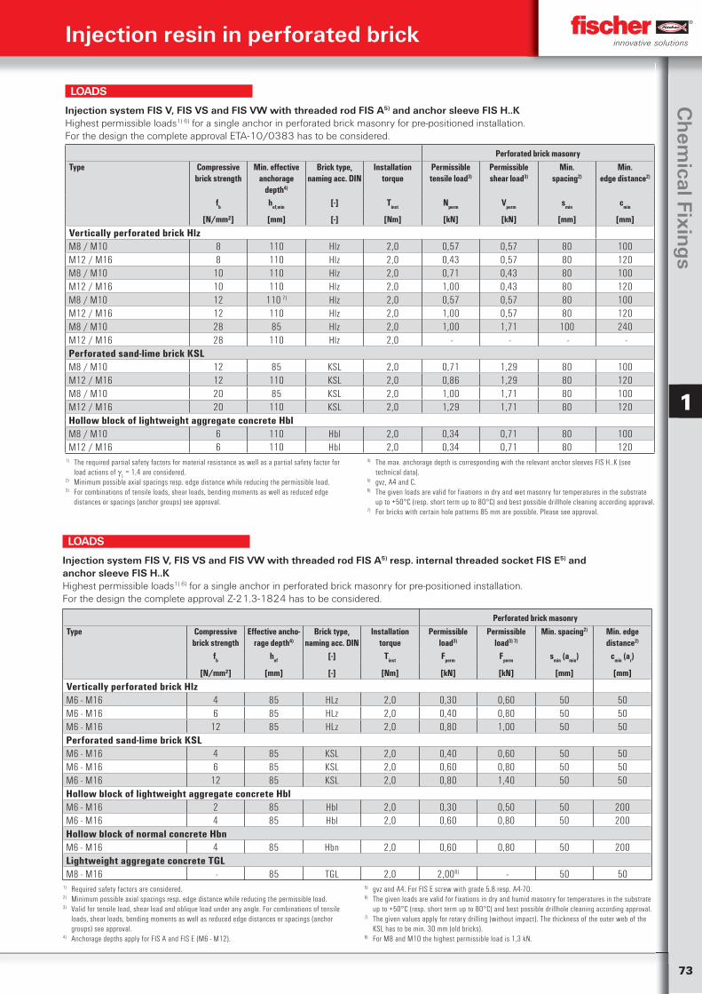
73
Ch
emical Fixin
gs
1
Perforated brick masonryType Compressive
brick strengthMin. effective
anchorage depth4)
Brick type, naming acc. DIN
Installation torque
Permissible tensile load3)
Permissible shear load3)
Min.spacing2)
Min.edge distance2)
fb hef,min [-] Tinst Nperm Vperm smin cmin
[N/mm²] [mm] [-] [Nm] [kN] [kN] [mm] [mm]
Vertically perforated brick HlzM8 / M10 8 110 Hlz 2,0 0,57 0,57 80 100M12 / M16 8 110 Hlz 2,0 0,43 0,57 80 120M8 / M10 10 110 Hlz 2,0 0,71 0,43 80 100M12 / M16 10 110 Hlz 2,0 1,00 0,43 80 120M8 / M10 12 110 7) Hlz 2,0 0,57 0,57 80 100M12 / M16 12 110 Hlz 2,0 1,00 0,57 80 120M8 / M10 28 85 Hlz 2,0 1,00 1,71 100 240M12 / M16 28 110 Hlz 2,0 - - - - Perforated sand-lime brick KSLM8 / M10 12 85 KSL 2,0 0,71 1,29 80 100M12 / M16 12 110 KSL 2,0 0,86 1,29 80 120M8 / M10 20 85 KSL 2,0 1,00 1,71 80 100M12 / M16 20 110 KSL 2,0 1,29 1,71 80 120Hollow block of lightweight aggregate concrete HblM8 / M10 6 110 Hbl 2,0 0,34 0,71 80 100M12 / M16 6 110 Hbl 2,0 0,34 0,71 80 120
Injection system FIS V, FIS VS and FIS VW with threaded rod FIS A5) and anchor sleeve FIS H..KHighest permissible loads1) 6) for a single anchor in perforated brick masonry for pre-positioned installation.For the design the complete approval ETA-10/0383 has to be considered.
1) The required partial safety factors for material resistance as well as a partial safety factor for load actions of
L = 1,4 are considered.
2) Minimum possible axial spacings resp. edge distance while reducing the permissible load.3) For combinations of tensile loads, shear loads, bending moments as well as reduced edge
distances or spacings (anchor groups) see approval.
4) The max. anchorage depth is corresponding with the relevant anchor sleeves FIS H..K (see technical data).
5) gvz, A4 and C.6) The given loads are valid for fixations in dry and wet masonry for temperatures in the substrate
up to +50°C (resp. short term up to 80°C) and best possible drillhole cleaning according approval.7) For bricks with certain hole patterns 85 mm are possible. Please see approval.
LOADS
Injection system FIS V, FIS VS and FIS VW with threaded rod FIS A5) resp. internal threaded socket FIS E5) and anchor sleeve FIS H..KHighest permissible loads1) 6) for a single anchor in perforated brick masonry for pre-positioned installation.For the design the complete approval Z-21.3-1824 has to be considered.
Perforated brick masonryType Compressive
brick strengthEffective ancho-
rage depth4)
Brick type, naming acc. DIN
Installation torque
Permissible load3)
Permissible load3) 7)
Min. spacing2) Min. edge distance2)
fb hef [-] Tinst Fperm Fperm smin (amin) cmin (ar)
[N/mm²] [mm] [-] [Nm] [kN] [kN] [mm] [mm]
Vertically perforated brick HlzM6 - M16 4 85 HLz 2,0 0,30 0,60 50 50M6 - M16 6 85 HLz 2,0 0,40 0,80 50 50M6 - M16 12 85 HLz 2,0 0,80 1,00 50 50Perforated sand-lime brick KSLM6 - M16 4 85 KSL 2,0 0,40 0,60 50 50M6 - M16 6 85 KSL 2,0 0,60 0,80 50 50M6 - M16 12 85 KSL 2,0 0,80 1,40 50 50Hollow block of lightweight aggregate concrete HblM6 - M16 2 85 Hbl 2,0 0,30 0,50 50 200M6 - M16 4 85 Hbl 2,0 0,60 0,80 50 200Hollow block of normal concrete HbnM6 - M16 4 85 Hbn 2,0 0,60 0,80 50 200Lightweight aggregate concrete TGLM8 - M16 - 85 TGL 2,0 2,008) - 50 50
1) Required safety factors are considered.2) Minimum possible axial spacings resp. edge distance while reducing the permissible load.3) Valid for tensile load, shear load and oblique load under any angle. For combinations of tensile
loads, shear loads, bending moments as well as reduced edge distances or spacings (anchor groups) see approval.
4) Anchorage depths apply for FIS A and FIS E (M6 - M12).
5) gvz and A4. For FIS E screw with grade 5.8 resp. A4-70.6) The given loads are valid for fixations in dry and humid masonry for temperatures in the substrate
up to +50°C (resp. short term up to 80°C) and best possible drillhole cleaning according approval.7) The given values apply for rotary drilling (without impact). The thickness of the outer web of the
KSL has to be min. 30 mm (old bricks).8) For M8 and M10 the highest permissible load is 1,3 kN.
LOADS
Injection resin in perforated brick
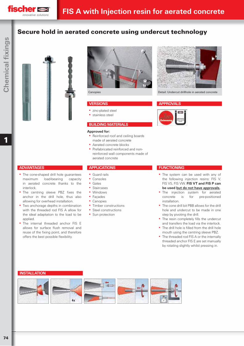
74
Ch
emic
al fi
xin
gs
1
FIS A with Injection resin for aerated concrete
Canopies Detail: Undercut drillhole in aerated concrete
ADVANTAGES
▪ The cone-shaped drill hole guarantees maximum load-bearing capacity in aerated concrete thanks to the interlock.
▪ The centring sleeve PBZ fixes the anchor in the drill hole, thus also allowing for overhead installation.
▪ Two anchorage depths in combination with the threaded rod FIS A allow for the ideal adaptation to the load to be applied.
▪ The internal threaded anchor FIS E allows for surface flush removal and reuse of the fixing point, and therefore offers the best possible flexibility.
VERSIONS
▪ zinc-plated steel ▪ stainless steel
FUNCTIONING
▪ The system can be used with any of the following injection resins: FIS V, FIS VS, FIS VW. FIS VT and FIS P can be used but do not have approvals.
▪ The injection system for aerated concrete is for pre-positioned installation.
▪ The cone drill bit PBB allows for the drill hole and undercut to be made in one step by pivoting the drill.
▪ The resin completely fills the undercut and transfers the load via the interlock.
▪ The drill hole is filled from the drill hole mouth using the centring sleeve PBZ.
▪ The threaded rod FIS A or the internally threaded anchor FIS E are set manually by rotating slightly whilst pressing in.
BUILDING MATERIALS
Approved for: ▪ Reinforced roof and ceiling boards
made of aerated concrete ▪ Aerated concrete blocks ▪ Prefabricated reinforced and non-
reinforced wall components made of aerated concrete
APPROVALS
Secure hold in aerated concrete using undercut technology
APPLICATIONS
▪ Guard rails ▪ Consoles ▪ Gates ▪ Staircases ▪ Windows ▪ Façades ▪ Canopies ▪ Timber constructions ▪ Steel constructions ▪ Sun protection
INSTALLATION
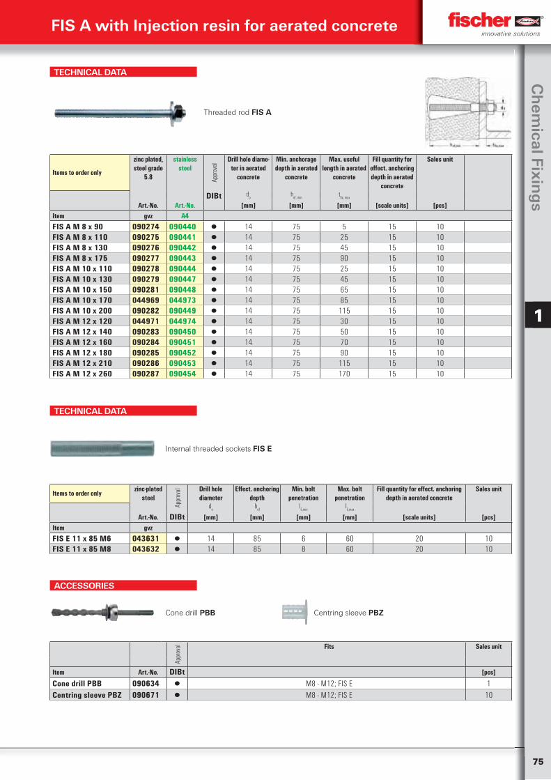
75
Ch
emical Fixin
gs
1
TECHNICAL DATA
Threaded rod FIS A
Items to order only
zinc plated, steel grade
5.8
stainless steel
Appr
oval
Drill hole diame-ter in aerated
concrete
Min. anchorage depth in aerated
concrete
Max. useful length in aerated
concrete
Fill quantity for effect. anchoring depth in aerated
concrete
Sales unit
DIBt do
hef, min
tfix, max
Art.-No. Art.-No. [mm] [mm] [mm] [scale units] [pcs]Item gvz A4
FIS A M 8 x 90 090274 090440 ▯ 14 75 5 15 10FIS A M 8 x 110 090275 090441 ▯ 14 75 25 15 10FIS A M 8 x 130 090276 090442 ▯ 14 75 45 15 10FIS A M 8 x 175 090277 090443 ▯ 14 75 90 15 10FIS A M 10 x 110 090278 090444 ▯ 14 75 25 15 10FIS A M 10 x 130 090279 090447 ▯ 14 75 45 15 10FIS A M 10 x 150 090281 090448 ▯ 14 75 65 15 10FIS A M 10 x 170 044969 044973 ▯ 14 75 85 15 10FIS A M 10 x 200 090282 090449 ▯ 14 75 115 15 10FIS A M 12 x 120 044971 044974 ▯ 14 75 30 15 10FIS A M 12 x 140 090283 090450 ▯ 14 75 50 15 10FIS A M 12 x 160 090284 090451 ▯ 14 75 70 15 10FIS A M 12 x 180 090285 090452 ▯ 14 75 90 15 10FIS A M 12 x 210 090286 090453 ▯ 14 75 115 15 10FIS A M 12 x 260 090287 090454 ▯ 14 75 170 15 10
TECHNICAL DATA
Internal threaded sockets FIS E
Items to order onlyzinc-plated
steel
Appr
oval Drill hole
diameterEffect. anchoring
depthMin. bolt
penetrationMax. bolt
penetrationFill quantity for effect. anchoring
depth in aerated concreteSales unit
do
hef
lE,min
lE,max
Art.-No. DIBt [mm] [mm] [mm] [mm] [scale units] [pcs]Item gvz
FIS E 11 x 85 M6 043631 ▯ 14 85 6 60 20 10FIS E 11 x 85 M8 043632 ▯ 14 85 8 60 20 10
ACCESSORIES
Cone drill PBB Centring sleeve PBZ
Appr
oval Fits Sales unit
Item Art.-No. DIBt [pcs]
Cone drill PBB 090634 ▯ M8 - M12; FIS E 1Centring sleeve PBZ 090671 ▯ M8 - M12; FIS E 10
FIS A with Injection resin for aerated concrete
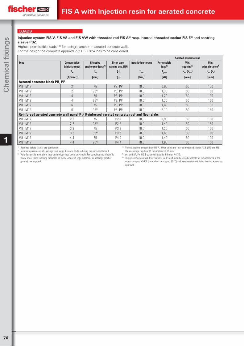
76
Ch
emic
al fi
xin
gs
1
Injection system FIS V, FIS VS and FIS VW with threaded rod FIS A5) resp. internal threaded socket FIS E5) and centring sleeve PBZ.Highest permissible loads1) 6) for a single anchor in aerated concrete walls.For the design the complete approval Z-21.3-1824 has to be considered.
Aerated concrete wallType Compressive
brick strengthEffective
anchorage depth4)
Brick type,naming acc. DIN
Installation torque Permissibleload3)
Min.spacing2)
Min.edge distance2)
fb hef [-] Tinst Fperm smin (amin) cmin (ar)
[N/mm²] [mm] [-] [Nm] [kN] [mm] [mm]
Aerated concrete block PB, PPM8 - M12 2 75 PB, PP 10,0 0,90 50 100M8 - M12 2 954) PB, PP 10,0 1,30 50 150M8 - M12 4 75 PB, PP 10,0 1,20 50 100M8 - M12 4 954) PB, PP 10,0 1,70 50 150M8 - M12 6 75 PB, PP 10,0 1,60 50 100M8 - M12 6 954) PB, PP 10,0 2,10 50 150Reinforced aerated concrete wall panel P / Reinforced aerated concrete roof and floor slabs M8 - M12 2,2 75 P2,2 10,0 0,90 50 100M8 - M12 2,2 954) P2,2 10,0 1,40 50 150M8 - M12 3,3 75 P3,3 10,0 1,20 50 100M8 - M12 3,3 954) P3,3 10,0 1,60 50 150M8 - M12 4,4 75 P4,4 10,0 1,40 50 100M8 - M12 4,4 954) P4,4 10,0 1,90 50 150
1) Required safety factors are considered.2) Minimum possible axial spacings resp. edge distance while reducing the permissible load.3) Valid for tensile load, shear load and oblique load under any angle. For combinations of tensile
loads, shear loads, bending moments as well as reduced edge distances or spacings (anchor groups) see approval.
4) Values apply to threaded rod FIS A. When using the internal threaded socket FIS E (M6 and M8) the anchorage depth is 85 mm instead of 95 mm.
5) gvz and A4. For FIS E screw with grade 5.8 resp. A4-70.6) The given loads are valid for fixations in dry and humid aerated concrete for temperatures in the
substrate up to +50°C (resp. short term up to 80°C) and best possible drillhole cleaning according approval.
LOADS
FIS A with Injection resin for aerated concrete
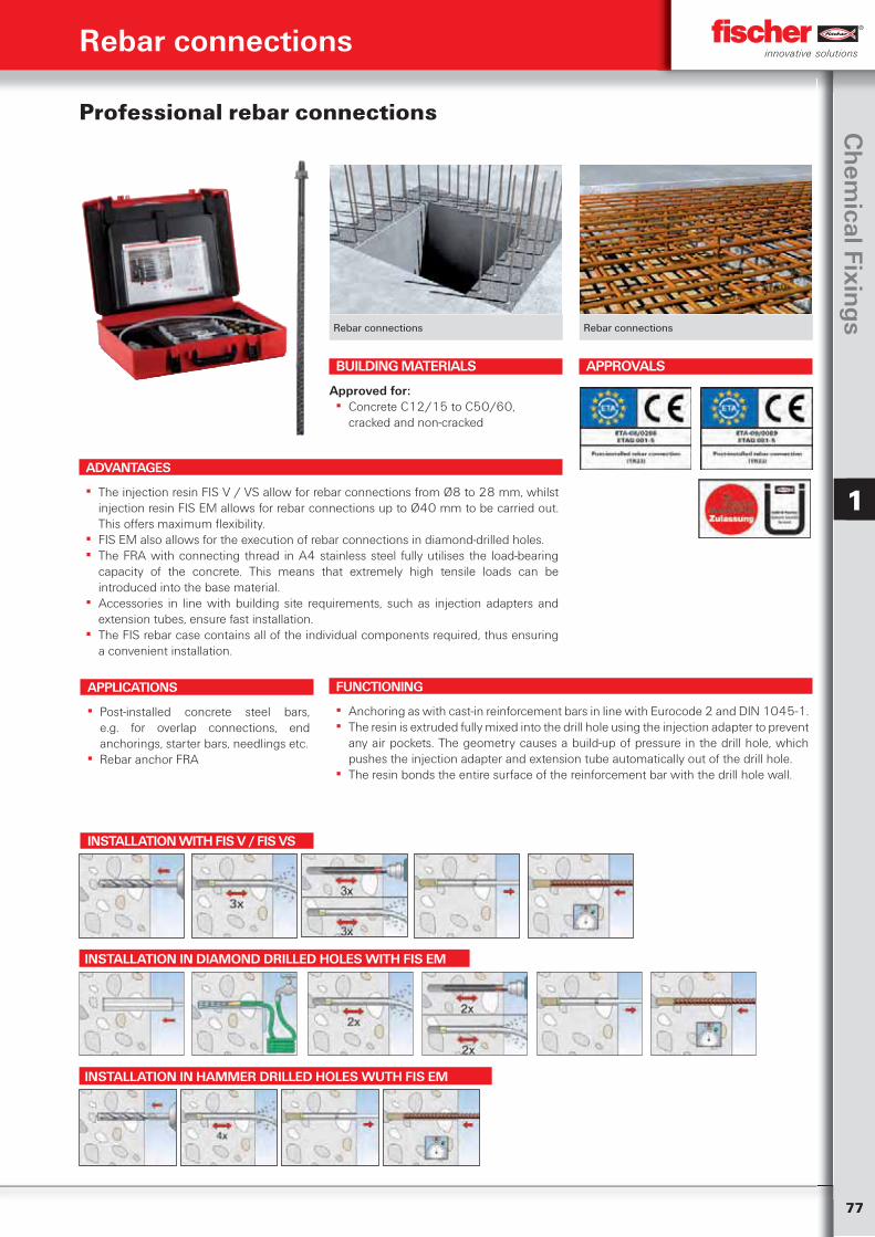
77
Ch
emical Fixin
gs
1
Rebar connections Rebar connections
Professional rebar connections
ADVANTAGES
▪ The injection resin FIS V / VS allow for rebar connections from Ø8 to 28 mm, whilst injection resin FIS EM allows for rebar connections up to Ø40 mm to be carried out. This offers maximum flexibility.
▪ FIS EM also allows for the execution of rebar connections in diamond-drilled holes. ▪ The FRA with connecting thread in A4 stainless steel fully utilises the load-bearing
capacity of the concrete. This means that extremely high tensile loads can be introduced into the base material.
▪ Accessories in line with building site requirements, such as injection adapters and extension tubes, ensure fast installation.
▪ The FIS rebar case contains all of the individual components required, thus ensuring a convenient installation.
APPLICATIONS
▪ Post-installed concrete steel bars, e.g. for overlap connections, end anchorings, starter bars, needlings etc.
▪ Rebar anchor FRA
FUNCTIONING
▪ Anchoring as with cast-in reinforcement bars in line with Eurocode 2 and DIN 1045-1. ▪ The resin is extruded fully mixed into the drill hole using the injection adapter to prevent
any air pockets. The geometry causes a build-up of pressure in the drill hole, which pushes the injection adapter and extension tube automatically out of the drill hole.
▪ The resin bonds the entire surface of the reinforcement bar with the drill hole wall.
BUILDING MATERIALS
Approved for: ▪ Concrete C12/15 to C50/60,
cracked and non-cracked
APPROVALS
Rebar connections
INSTALLATION WITH FIS V / FIS VS
INSTALLATION IN DIAMOND DRILLED HOLES WITH FIS EM
INSTALLATION IN HAMMER DRILLED HOLES WUTH FIS EM
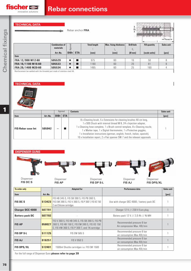
78
Ch
emic
al fi
xin
gs
1
Rebar connections
TECHNICAL DATA
Rebar anchor FRA
Combination of materials
Appr
oval Total length Max. fixing thickness Drill-hole Fill quantity Sales unit
l tfix
d0
Art.-No. DIBt ETA [mm] [mm] [Ø mm] [scale units] [pcs]Item
FRA 12/900 M12-60 505529 ▯ ■ 975 60 16 50 8FRA 16/1100 M16-60 505533 ▯ ■ 1180 60 20 81 8FRA 20/1400 M20-60 505534 ▯ ■ 1485 60 25 160 4Reinforcement bar welded with the threaded part made of stainless steel A4.
TECHNICAL DATA
Approval Contents Sales unit
Item Art.-No. DIBt ETA [pcs]
FIS-Rebar case Int 505942 — ■
8 x Cleaning brush, 5 x Extensions for cleaning brushes 40 cm long, 1 x SDS Chuck with internal thread M 8, 24 x Injection adapter,
1 x Cleaning hose complete, 1 x Brush control template, 8 x Cleaning nozzle, 1 x Marker tape, 1 x Digital thermometer, 1 x Protective goggles,
1 x Installation instructions (german, english, french, italian, spanish), 10 x Installation report, 2 x Flat spanner SW 7 and the relevant approvals
1
To order only Adapted for Performance data Sales unit
Item Art.-No. [pcs]
FIS DC S 513423FIS HB 345 S, FIS SB 390 S, FIS PB 360 S,FIS EM 390 S, FIS V 360 S, FIS P 300 T, FIS VS 150 C and Silicone cartridges
Use with charger DCC 4000 / battery pack DC 1
Charger DCC 4000 507791 - Charger 12 V // 230 V Euro plug 1
Battery pack DC 507792 - Battery pack 12 V // 2,0 Ah // Ni-MH 1
FIS AP 058027FIS V 360 S, FIS HB 345 S, FIS SB 390 S, FIS PB 360 S, FIS HB 150 C, FIS EM 390 S, FIS VS 150 C, FIS VW 360 S, FIS P 300 T, and 1K-cartridge
Recommended pressure 6 barAir compression Max. 40I/min
1
FIS DP S-L 511125 FIS EM 585 SRecommended pressure 6 barair consumption Max 40I/min
1
FIS AJ 016251 FIS V 950 SRecommended pressure 6 barair consumption Max 40I/min
1
FIS DPS/XL 512401 1500ml Shuttle cartridges i.e. FIS EM 1500Recommended pressure 6 barair consumption Max 40I/min
1
Dispenser FIS DC S
DispenserFIS DP S-L
DispenserFIS DPS/XL
Dispenser FIS AP
Dispenser FIS AJ
DISPENSER GUNS
For the full range of Dispenser Guns please refer to page 39
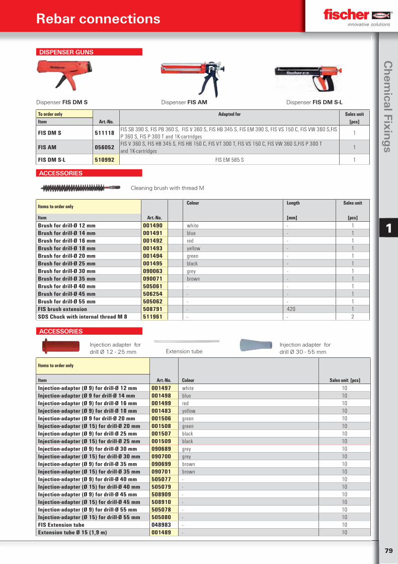
79
Ch
emical Fixin
gs
1
DISPENSER GUNS
Dispenser FIS DM S Dispenser FIS AM Dispenser FIS DM S-L
To order only Adapted for Sales unitItem Art.-No. [pcs]
FIS DM S 511118 FIS SB 390 S, FIS PB 360 S, FIS V 360 S, FIS HB 345 S, FIS EM 390 S, FIS VS 150 C, FIS VW 360 S,FIS P 360 S, FIS P 300 T and 1K-cartridges
1
FIS AM 056052 FIS V 360 S, FIS HB 345 S, FIS HB 150 C, FIS VT 300 T, FIS VS 150 C, FIS VW 360 S,FIS P 300 T and 1K-cartridges
1
FIS DM S-L 510992 FIS EM 585 S 1
Rebar connections
ACCESSORIES
Items to order onlyColour Length Sales unit
Item Art.-No. [mm] [pcs]
Brush for drill-Ø 12 mm 001490 white - 1Brush for drill-Ø 14 mm 001491 blue - 1Brush for drill-Ø 16 mm 001492 red - 1Brush for drill-Ø 18 mm 001493 yellow - 1Brush for drill-Ø 20 mm 001494 green - 1Brush for drill-Ø 25 mm 001495 black - 1Brush for drill-Ø 30 mm 090063 grey - 1Brush for drill-Ø 35 mm 090071 brown - 1Brush for drill-Ø 40 mm 505061 - - 1Brush for drill-Ø 45 mm 506254 - - 1Brush for drill-Ø 55 mm 505062 - - 1FIS brush extension 508791 - 420 1SDS Chuck with internal thread M 8 511961 - - 2
Cleaning brush with thread M
ACCESSORIES
Items to order only
Art.-No. Colour Sales unit [pcs]Item
Injection-adapter (Ø 9) for drill-Ø 12 mm 001497 white 10Injection-adapter (Ø 9 for drill-Ø 14 mm 001498 blue 10Injection-adapter (Ø 9) for drill-Ø 16 mm 001499 red 10Injection-adapter (Ø 9) for drill-Ø 18 mm 001483 yellow 10Injection-adapter (Ø 9 for drill-Ø 20 mm 001506 green 10Injection-adapter (Ø 15) for drill-Ø 20 mm 001508 green 10Injection-adapter (Ø 9) for drill-Ø 25 mm 001507 black 10Injection-adapter (Ø 15) for drill-Ø 25 mm 001509 black 10Injection-adapter (Ø 9) for drill-Ø 30 mm 090689 grey 10Injection-adapter (Ø 15) for drill-Ø 30 mm 090700 grey 10Injection-adapter (Ø 9) for drill-Ø 35 mm 090699 brown 10Injection-adapter (Ø 15) for drill-Ø 35 mm 090701 brown 10Injection-adapter (Ø 9) for drill-Ø 40 mm 505077 - 10Injection-adapter (Ø 15) for drill-Ø 40 mm 505079 - 10Injection-adapter (Ø 9) for drill-Ø 45 mm 508909 - 10Injection-adapter (Ø 15) for drill-Ø 45 mm 508910 - 10Injection-adapter (Ø 9) for drill-Ø 55 mm 505078 - 10Injection-adapter (Ø 15) for drill-Ø 55 mm 505080 - 10FIS Extension tube 048983 - 10Extension tube Ø 15 (1,9 m) 001489 - 10
Extension tubeInjection adapter for drill Ø 12 - 25 mm
Injection adapter fordrill Ø 30 - 55 mm
80
Ch
emic
al fi
xin
gs
1
Cracked or Non-cracked concreteRebar Basic anchorage length4)
for FIS V, FIS VSBasic anchorage length4)
for FIS EMMax. permissibleembedment depth
Max. design resistancefor tensile load
Max. permissibletensile load
lb,rqd lb,rqd max lv NRd,s3) Nperm,s
3)
[mm] [mm] [mm] [kN] [kN]
Ø 8 mm 378 378 1800 21,9 15,6Ø 10 mm 473 473 1800 34,1 24,4Ø 12 mm 567 567 1800 49,2 35,1Ø 14 mm 662 662 1800 66,9 47,8Ø 16 mm 756 756 1800 87,4 62,4Ø 20 mm 945 945 1800 136,6 97,6Ø 25 mm 1181 1181 2000 213,4 152,4Ø 28 mm 1323 1323 2000 267,7 191,2Ø 32 mm - 1512 2000 349,7 249,8Ø 36 mm - 1701 2000 442,6 316,1Ø 40 mm - 1890 2000 546,4 390,3
Injection system FIS V, FIS VS and FIS EM with Rebars from steel type BSt 500 S5)
Design resistant loads and permissible tensile loads1) 6) of a single post-installed Rebar in concrete C20/252).For the design and planning the complete approval ETA - 09/0089 and ETA - 08/0266 have to be considered.
1) The partial safety factors for material resistance as regulated in the European Standard EN 1992-1-1 as well as a partial safety factor for load actions of
L = 1,4 are considered.
2) The ETA-approvals for FIS V and FIS EM allow post-installed rebar connections in concrete C12/15 up to C50/60. When using another concrete strength class the given basic anchorage length will change.
3) When using the full steel capacity.4) Basic anchorage length" according EN 1992-1-1, chapter 8.4.3 for concrete strength class
C20/25 for "good bond conditions"5) Rebars with a characteristic yield strength f
yk = 400 - 600 N/mm² according EN 1992-1-1
Annex C,Table C.1 and C.2N are permitted. When using an other steel quality the given basic anchorage length as well as the steel capacity (see foot note 3) will change.
6) Fixations with post-installed rebars with FIS V and FIS EM are permitted in dry and wet concrete for temperatures in the substrate up to +50°C (resp. short term up to 80°C) and best possible drillhole cleaning according approval.
7) For determination of the installation measures (minimum concrete cover, spacings e.g.) as well as an eventually required transverse reinforcement see EN 1992-1-1 and the general instruction rules of the approvals.
LOADS
Rebar connections
Cracked or Non-cracked concreteType Basic
anchorage length4)
Max. effectiveembedment depth
Max.embedment depth
Installation torque Max. design resistance for tensile load
Max. permissible tensile load
lb,rqd max lv max le,ges Tinst NRd,s3) Nzul,s
3)
[mm] [mm] [mm] [Nm] [kN] [kN]
FRA 12/900 M12 567 800 900 50,0 49,2 35,1FRA 16/1100 M16 756 1000 1100 100,0 87,4 62,4FRA 20/1400 M20 945 1300 1400 150,0 136,6 97,6
Injection system FIS V, FIS VS and FIS EM with Rebar anchor FRA5)
Highest permissible tensile loads1) 6) for a single Rebar anchor in concrete C20/252).For the design and planning the complete approvals ETA - 09/0089 and ETA - 08/0266 have to be considered.
1) The partial safety factors for material resistance as regulated in the European Standard EN 1992-1-1 as well as a partial safety factor for load actions of
L = 1,4 are considered.
2) The ETA-approvals for FIS V and FIS EM allow post-installed rebar connections in concrete C12/15 up to C50/60. When using another concrete strength class the given basic anchorage length will change.
3) When using the full steel capacity.4) Basic anchorage length according EN 1992-1-1, chapter 8.4.3 for concrete strength class C20/25
for „good bond conditions“
5) Reinforcement bar BSt 500 S according EN 1992-1-1 Annex C,Table C.1 and C.2N.6) Fixations with post-installed Rebars anchors FRA with FIS V and FIS EM are permitted in dry and
wet concrete for temperatures in the substrate up to +50°C (resp. short term up to 80°C) and best possible drillhole cleaning according approval.
7) For determination of the installation measures (minimum concrete cover, spacings e.g.) as well as an eventually required transverse reinforcement see EN 1992-1-1 and the general instruction rules of the approvals.
LOADS
ACCESSORIES
Items to order only
Art.-No. Fits Sales unit [pcs]Item
Compressed air nozzle D12-D15 511956 Drill diameter Ø 12 - 15 mm 2Compressed air nozzle D16-D19 511957 Drill diameter Ø 16 - 19 mm 2Compressed air nozzle D20-D25 511958 Drill diameter Ø 20 - 25 mm 2Compressed air nozzle D30-D35 511959 Drill diameter Ø 30 - 35 mm 2Compressed air nozzle D40-D55 511960 Drill diameter Ø 40 - 45 mm 2
Compressed air nozzle
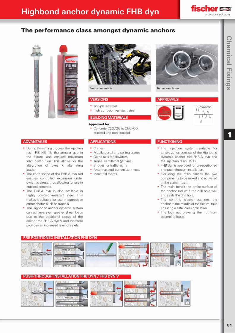
81
Ch
emical Fixin
gs
1
Production robots Tunnel ventilators
The performance class amongst dynamic anchors
ADVANTAGES
▪ During the setting process, the injection resin FIS HB fills the annular gap in the fixture, and ensures maximum load distribution. This allows for the absorption of dynamic alternating loads.
▪ The cone shape of the FHB-A dyn rod ensures controlled expansion under dynamic stress, thus allowing for use in cracked concrete.
▪ The FHB-A dyn is also available in highly corrosion-resistant steel. This makes it suitable for use in aggressive atmospheres such as tunnels.
▪ The Highbond anchor dynamic system can achieve even greater shear loads due to the additional sleeve of the anchor rod FHB-A dyn V and therefore provides an increased level of safety.
VERSIONS
▪ zinc-plated steel ▪ high corrosion resistant steel
APPLICATIONS
▪ Cranes ▪ Mobile portal and ceiling cranes ▪ Guide rails for elevators ▪ Tunnel ventilators (jet fans) ▪ Bridges for traffic signs ▪ Antennas and transmitter masts ▪ Industrial robots
FUNCTIONING
▪ The injection system suitable for tensile zones consists of the Highbond dynamic anchor rod FHB-A dyn and the injection resin FIS HB.
▪ FHB dyn is approved for pre-positioned and push-through installation.
▪ Extruding the resin causes the two components to be mixed and activated in the static mixer.
▪ The resin bonds the entire surface of the anchor rod with the drill hole wall and seals the drill hole.
▪ The centring sleeve positions the anchor in the middle of the fixture, thus ensuring a safe load application.
▪ The lock nut prevents the nut from becoming loose.
BUILDING MATERIALS
Approved for: ▪ Concrete C20/25 to C50/60,
cracked and non-cracked
APPROVALS
Highbond anchor dynamic FHB dyn
PRE-POSITIONED INSTALLATION FHB DYN
PUSH-THROUGH INSTALLATION FHB DYN / FHB DYN V
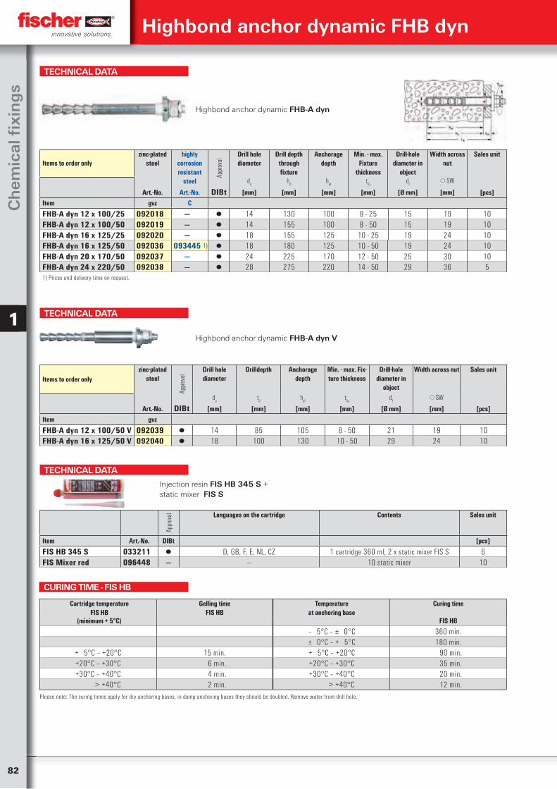
82
Ch
emic
al fi
xin
gs
1
TECHNICAL DATA
Highbond anchor dynamic FHB-A dyn
Items to order onlyzinc-plated
steelhighly
corrosion resistant
steel
Appr
oval
Drill hole diameter
Drill depth through fixture
Anchorage depth
Min. - max. Fixture
thickness
Drill-hole diameter in
object
Width across nut
Sales unit
do
h0
hef
tfix
df
SW
Art.-No. Art.-No. DIBt [mm] [mm] [mm] [mm] [Ø mm] [mm] [pcs]Item gvz C
FHB-A dyn 12 x 100/25 092018 — ▯ 14 130 100 8 - 25 15 19 10FHB-A dyn 12 x 100/50 092019 — ▯ 14 155 100 8 - 50 15 19 10FHB-A dyn 16 x 125/25 092020 — ▯ 18 155 125 10 - 25 19 24 10FHB-A dyn 16 x 125/50 092036 093445 1) ▯ 18 180 125 10 - 50 19 24 10FHB-A dyn 20 x 170/50 092037 — ▯ 24 225 170 12 - 50 25 30 10FHB-A dyn 24 x 220/50 092038 — ▯ 28 275 220 14 - 50 29 36 51) Prices and delivery time on request.
TECHNICAL DATA
Highbond anchor dynamic FHB-A dyn V
Items to order onlyzinc-plated
steel
Appr
oval
Drill hole diameter
Drilldepth Anchorage depth
Min. - max. Fix-ture thickness
Drill-hole diameter in
object
Width across nut Sales unit
do
td
hef
tfix
df
SW
Art.-No. DIBt [mm] [mm] [mm] [mm] [Ø mm] [mm] [pcs]Item gvz
FHB-A dyn 12 x 100/50 V 092039 ▯ 14 85 105 8 - 50 21 19 10FHB-A dyn 16 x 125/50 V 092040 ▯ 18 100 130 10 - 50 29 24 10
TECHNICAL DATA
Injection resin FIS HB 345 S + static mixer FIS S
Appr
oval Languages on the cartridge Contents Sales unit
Item Art.-No. DIBt [pcs]
FIS HB 345 S 033211 ▯ D, GB, F, E, NL, CZ 1 cartridge 360 ml, 2 x static mixer FIS S 6FIS Mixer red 096448 — — 10 static mixer 10
Cartridge temperatureFIS HB
Gelling timeFIS HB
Temperatureat anchoring base
Curing time
(minimum + 5°C) FIS HB
‒ 5°C – ± 0°C 360 min.± 0°C – + 5°C 180 min.
+ 5°C – +20°C 15 min. + 5°C – +20°C 90 min.+20°C – +30°C 6 min. +20°C – +30°C 35 min.+30°C – +40°C 4 min. +30°C – +40°C 20 min. > +40°C 2 min. > +40°C 12 min.
Please note: The curing times apply for dry anchoring bases, in damp anchoring bases they should be doubled. Remove water from drill hole.
CURING TIME - FIS HB
Highbond anchor dynamic FHB dyn
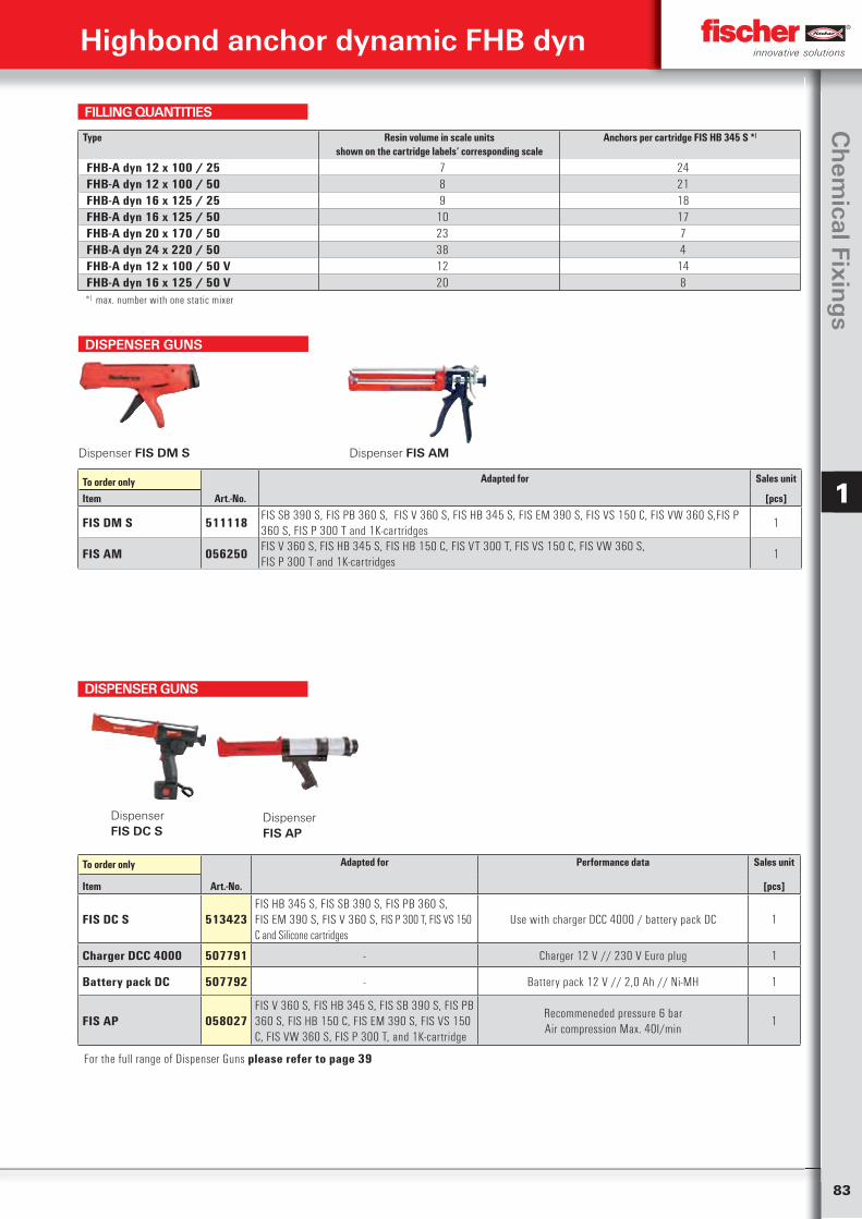
83
Ch
emical Fixin
gs
1
Highbond anchor dynamic FHB dyn
Type Resin volume in scale unitsshown on the cartridge labels‘ corresponding scale
Anchors per cartridge FIS HB 345 S *)
FHB-A dyn 12 x 100 / 25 7 24FHB-A dyn 12 x 100 / 50 8 21FHB-A dyn 16 x 125 / 25 9 18FHB-A dyn 16 x 125 / 50 10 17FHB-A dyn 20 x 170 / 50 23 7FHB-A dyn 24 x 220 / 50 38 4FHB-A dyn 12 x 100 / 50 V 12 14FHB-A dyn 16 x 125 / 50 V 20 8*) max. number with one static mixer
FILLING QUANTITIES
DISPENSER GUNS
Dispenser FIS DM S Dispenser FIS AM
To order only Adapted for Sales unit
Item Art.-No. [pcs]
FIS DM S 511118 FIS SB 390 S, FIS PB 360 S, FIS V 360 S, FIS HB 345 S, FIS EM 390 S, FIS VS 150 C, FIS VW 360 S,FIS P 360 S, FIS P 300 T and 1K-cartridges
1
FIS AM 056250 FIS V 360 S, FIS HB 345 S, FIS HB 150 C, FIS VT 300 T, FIS VS 150 C, FIS VW 360 S, FIS P 300 T and 1K-cartridges
1
To order only Adapted for Performance data Sales unit
Item Art.-No. [pcs]
FIS DC S 513423FIS HB 345 S, FIS SB 390 S, FIS PB 360 S,FIS EM 390 S, FIS V 360 S, FIS P 300 T, FIS VS 150 C and Silicone cartridges
Use with charger DCC 4000 / battery pack DC 1
Charger DCC 4000 507791 - Charger 12 V // 230 V Euro plug 1
Battery pack DC 507792 - Battery pack 12 V // 2,0 Ah // Ni-MH 1
FIS AP 058027FIS V 360 S, FIS HB 345 S, FIS SB 390 S, FIS PB 360 S, FIS HB 150 C, FIS EM 390 S, FIS VS 150 C, FIS VW 360 S, FIS P 300 T, and 1K-cartridge
Recommeneded pressure 6 barAir compression Max. 40I/min
1
Dispenser FIS DC S
Dispenser FIS AP
DISPENSER GUNS
For the full range of Dispenser Guns please refer to page 39
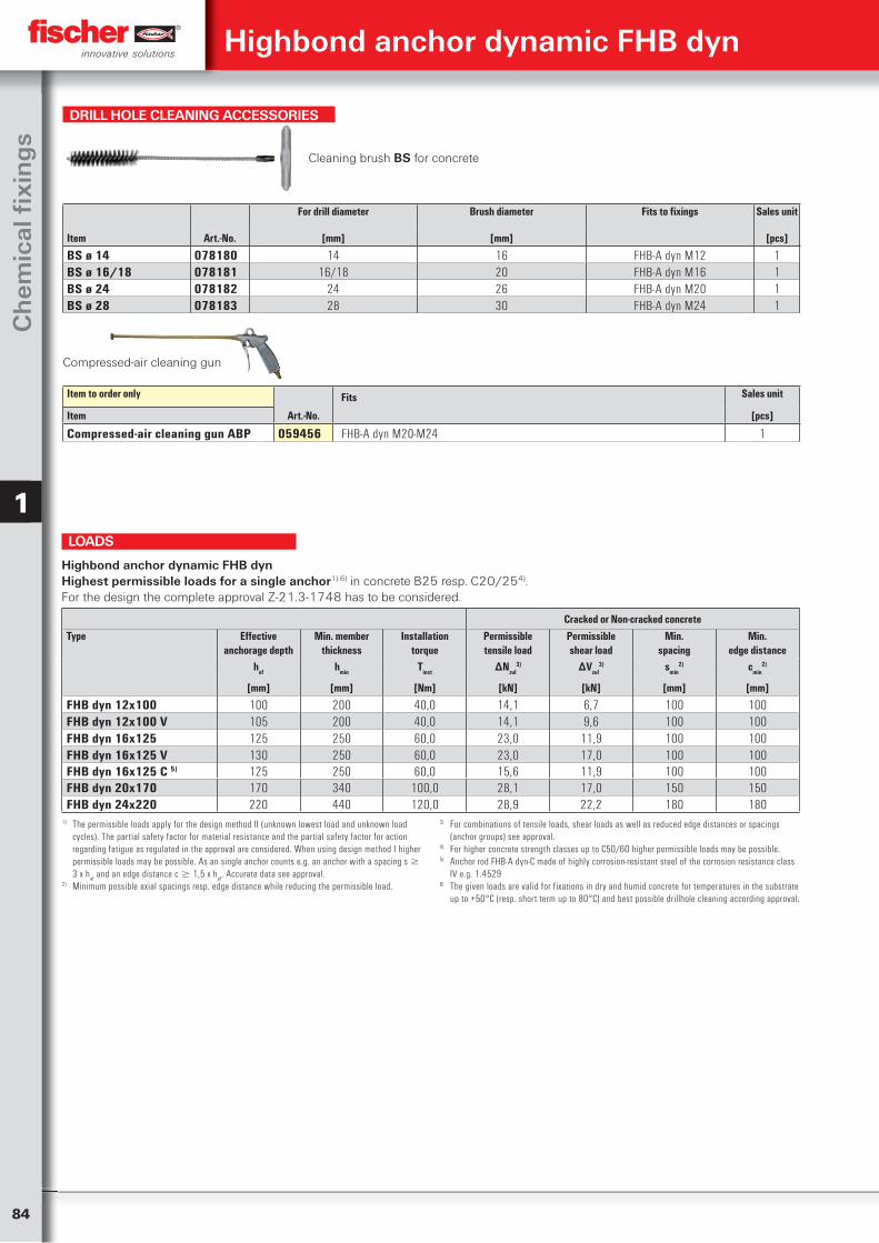
84
Ch
emic
al fi
xin
gs
1
Cracked or Non-cracked concreteType Effective
anchorage depthMin. member
thicknessInstallation
torquePermissibletensile load
Permissibleshear load
Min.spacing
Min.edge distance
hef hmin Tinst ∆Nzul3) ∆Vzul
3) smin2) cmin
2)
[mm] [mm] [Nm] [kN] [kN] [mm] [mm]
FHB dyn 12x100 100 200 40,0 14,1 6,7 100 100FHB dyn 12x100 V 105 200 40,0 14,1 9,6 100 100FHB dyn 16x125 125 250 60,0 23,0 11,9 100 100FHB dyn 16x125 V 130 250 60,0 23,0 17,0 100 100FHB dyn 16x125 C 5) 125 250 60,0 15,6 11,9 100 100FHB dyn 20x170 170 340 100,0 28,1 17,0 150 150FHB dyn 24x220 220 440 120,0 28,9 22,2 180 180
Highbond anchor dynamic FHB dynHighest permissible loads for a single anchor1) 6) in concrete B25 resp. C20/254).For the design the complete approval Z-21.3-1748 has to be considered.
1) The permissible loads apply for the design method II (unknown lowest load and unknown load cycles). The partial safety factor for material resistance and the partial safety factor for action regarding fatigue as regulated in the approval are considered. When using design method I higher permissible loads may be possible. As an single anchor counts e.g. an anchor with a spacing s 3 x h
ef and an edge distance c 1,5 x h
ef. Accurate data see approval.
2) Minimum possible axial spacings resp. edge distance while reducing the permissible load.
3) For combinations of tensile loads, shear loads as well as reduced edge distances or spacings (anchor groups) see approval.
4) For higher concrete strength classes up to C50/60 higher permissible loads may be possible.5) Anchor rod FHB-A dyn-C made of highly corrosion-resistant steel of the corrosion resistance class
IV e.g. 1.45296) The given loads are valid for fixations in dry and humid concrete for temperatures in the substrate
up to +50°C (resp. short term up to 80°C) and best possible drillhole cleaning according approval.
LOADS
DRILL HOLE CLEANING ACCESSORIES
Cleaning brush BS for concrete
For drill diameter Brush diameter Fits to fixings Sales unit
Item Art.-No. [mm] [mm] [pcs]
BS ø 14 078180 14 16 FHB-A dyn M12 1BS ø 16/18 078181 16/18 20 FHB-A dyn M16 1BS ø 24 078182 24 26 FHB-A dyn M20 1BS ø 28 078183 28 30 FHB-A dyn M24 1
Compressed-air cleaning gun
Item to order only Fits Sales unit
Item Art.-No. [pcs]
Compressed-air cleaning gun ABP 059456 FHB-A dyn M20-M24 1
Highbond anchor dynamic FHB dyn
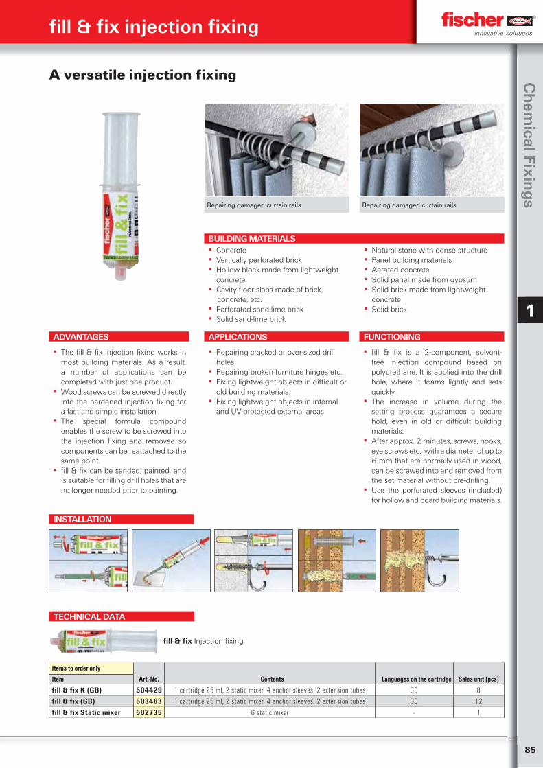
85
Ch
emical Fixin
gs
1
fill & fix injection fixing
Repairing damaged curtain rails Repairing damaged curtain rails
A versatile injection fixing
ADVANTAGES
▪ The fill & fix injection fixing works in most building materials. As a result, a number of applications can be completed with just one product.
▪ Wood screws can be screwed directly into the hardened injection fixing for a fast and simple installation.
▪ The special formula compound enables the screw to be screwed into the injection fixing and removed so components can be reattached to the same point.
▪ fill & fix can be sanded, painted, and is suitable for filling drill holes that are no longer needed prior to painting.
APPLICATIONS
▪ Repairing cracked or over-sized drill holes
▪ Repairing broken furniture hinges etc. ▪ Fixing lightweight objects in difficult or
old building materials. ▪ Fixing lightweight objects in internal
and UV-protected external areas
FUNCTIONING
▪ fill & fix is a 2-component, solvent-free injection compound based on polyurethane. It is applied into the drill hole, where it foams lightly and sets quickly.
▪ The increase in volume during the setting process guarantees a secure hold, even in old or difficult building materials.
▪ After approx. 2 minutes, screws, hooks, eye screws etc, with a diameter of up to 6 mm that are normally used in wood, can be screwed into and removed from the set material without pre-drilling.
▪ Use the perforated sleeves (included) for hollow and board building materials.
TECHNICAL DATA
fill & fix Injection fixing
Items to order only
Art.-No. Contents Languages on the cartridge Sales unit [pcs]Item
fill & fix K (GB) 504429 1 cartridge 25 ml, 2 static mixer, 4 anchor sleeves, 2 extension tubes GB 8fill & fix (GB) 503463 1 cartridge 25 ml, 2 static mixer, 4 anchor sleeves, 2 extension tubes GB 12fill & fix Static mixer 502735 6 static mixer - 1
INSTALLATION
BUILDING MATERIALS ▪ Concrete ▪ Vertically perforated brick ▪ Hollow block made from lightweight
concrete ▪ Cavity floor slabs made of brick,
concrete, etc. ▪ Perforated sand-lime brick ▪ Solid sand-lime brick
▪ Natural stone with dense structure ▪ Panel building materials ▪ Aerated concrete ▪ Solid panel made from gypsum ▪ Solid brick made from lightweight
concrete ▪ Solid brick
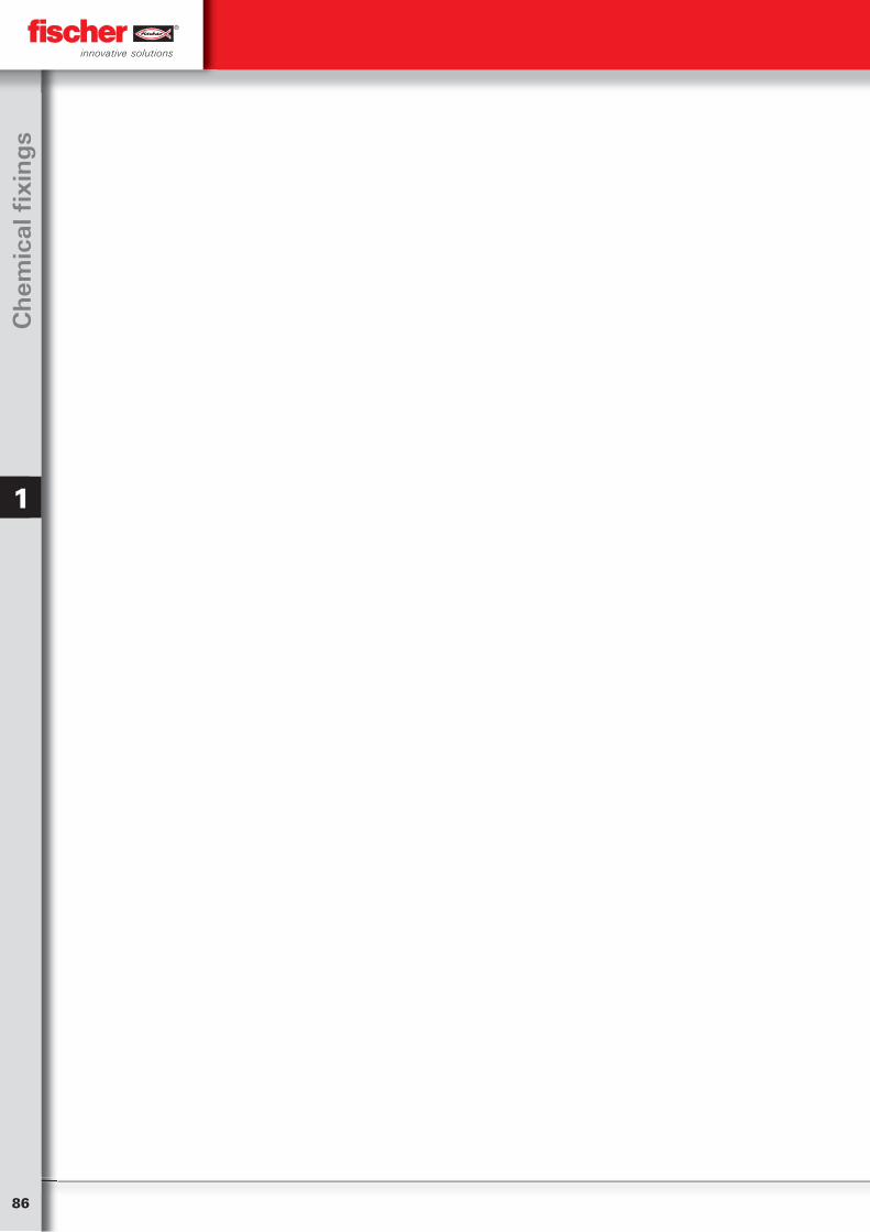
86
Ch
emic
al fi
xin
gs
1
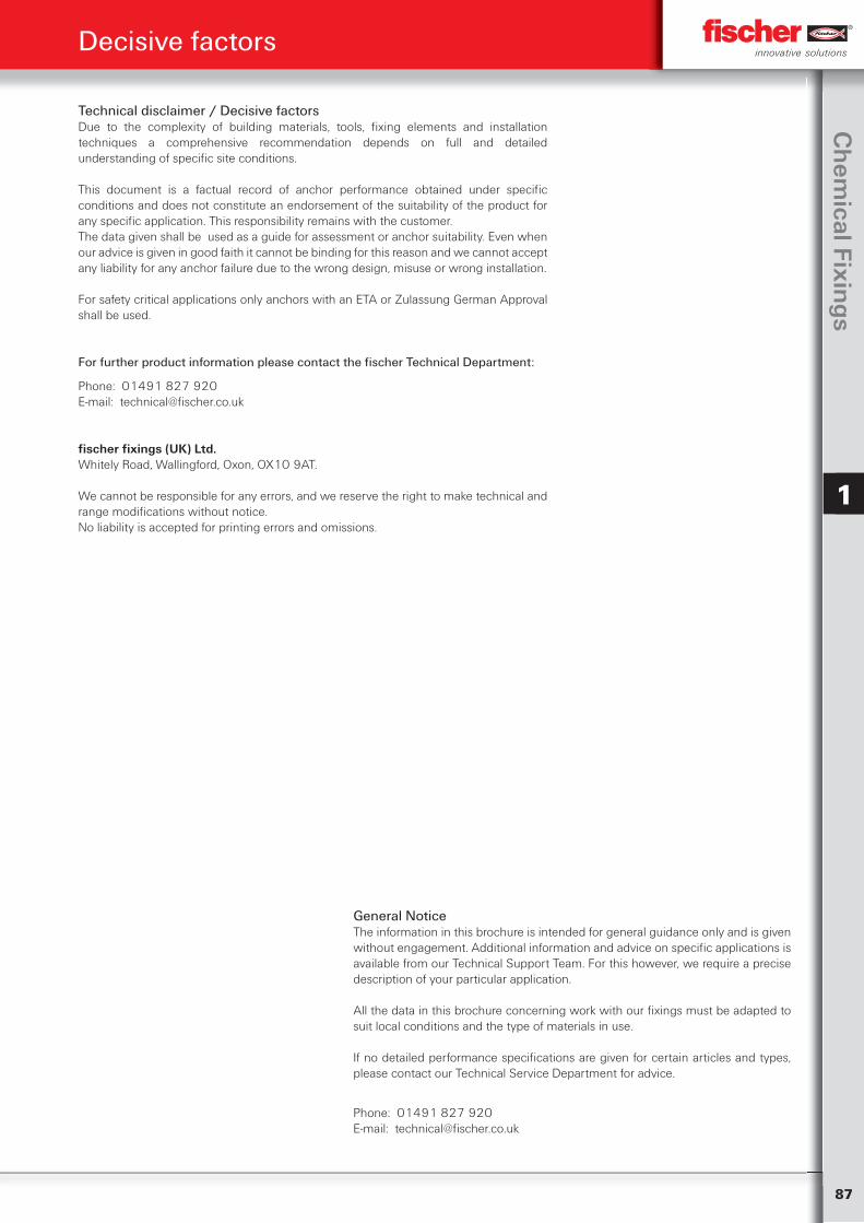
87
Ch
emical Fixin
gs
1
Decisive factors
Technical disclaimer / Decisive factors Due to the complexity of building materials, tools, fixing elements and installation techniques a comprehensive recommendation depends on full and detailed understanding of specific site conditions.
This document is a factual record of anchor performance obtained under specific conditions and does not constitute an endorsement of the suitability of the product for any specific application. This responsibility remains with the customer.The data given shall be used as a guide for assessment or anchor suitability. Even when our advice is given in good faith it cannot be binding for this reason and we cannot accept any liability for any anchor failure due to the wrong design, misuse or wrong installation.
For safety critical applications only anchors with an ETA or Zulassung German Approval shall be used.
For further product information please contact the fischer Technical Department:
Phone: 01491 827 920E-mail: [email protected]
fischer fixings (UK) Ltd.Whitely Road, Wallingford, Oxon, OX10 9AT.
We cannot be responsible for any errors, and we reserve the right to make technical and range modifications without notice.No liability is accepted for printing errors and omissions.
General NoticeThe information in this brochure is intended for general guidance only and is given without engagement. Additional information and advice on specific applications is available from our Technical Support Team. For this however, we require a precise description of your particular application.
All the data in this brochure concerning work with our fixings must be adapted to suit local conditions and the type of materials in use.
If no detailed performance specifications are given for certain articles and types, please contact our Technical Service Department for advice.
Phone: 01491 827 920E-mail: [email protected]
Contacts
fischer fixings UK Ltd.Whitely RoadOxon OX10 9AT WallingfordGreat BritainPhone (0044) 1491 827900Fax (0044) 1491 827953E-mail [email protected]
Your dealer:
01/2013
www.fischer.co.uk
Ch
emic
al f
ixin
gs /
1 o
f 1
2 P
rod
uct
sec
tion
s /
01
/20
13
· (V
1)
· Pri
nte
d in
th
e U
K
Technical Service If you need any assistance, simply contact your local fischer representative. For more specialised application problems please contact our Technical Services Team.
fischer fixings UK Ltd. Wallingford, Oxon, OX10 9AT.
Phone 01491 827 920 e-mail: [email protected]
Technical TrainingWe also offer training seminars suited to your individual needs and requirements. Please call the number above to find out more