Embed Size (px)
Citation preview

0900960 Rev: B (10/10) Page 1 of 40
Chem-Trak Jr. (EDP) Instruction Manual

Page 2 of 40 0900960 Rev: B (10/10)
TABLE OF CONTENTS
Specifications ....................................................................................................... 3
System Overview .................................................................................................. 4
Operation .............................................................................................................. 5
Installation ............................................................................................................ 6
SIB and Interrupt Modules .................................................................................... 8
Wiring Diagram ..................................................................................................... 9
Washer Hold Function ........................................................................................ 10
Keypad Diagram ................................................................................................. 12
Keypad Descriptions ........................................................................................... 13
Formula Selector(s) ............................................................................................ 14
Programming (Introduction) ................................................................................ 15
Menu Map........................................................................................................... 16
Menu 1: Memory Functions ...................................................................... 17
Menu 2: Setup Routines ............................................................................ 19
Menu 3: Report Setup Routines ............................................................... 25
Menu 4: Maintenance Schedule ............................................................... 29
Menu 5: Programming Routines .............................................................. 30
Menu 6: Pump Prime Routines ................................................................. 33
Maintenance ....................................................................................................... 34
Troubleshooting .................................................................................................. 35
Parts Diagrams ................................................................................................... 36
Warranty Information .......................................................................................... 40
Knight Locations ................................................................................................. 40
CAUTION: Wear protective clothing and eyewear when dispensing chemicals or
other materials. Observe safety handling instructions (MSDS) of chemical mfrs.
CAUTION: To avoid severe or fatal shock, always disconnect main power when
servicing the unit.
CAUTION: When installing any equipment, ensure that all national and local safety, electrical, and plumbing codes are met.

0900960 Rev: B (10/10) Page 3 of 40
SPECIFICATIONS
Max Number of Washers ...................................................................................... 4
Max Number of Chemicals ................................................................................... 6
Pump Cabinet ............................... 46‖ W x 13‖ H x 11.5‖ D (1.17m x .33m x .29m)
Controller .......................................... 15‖ W x 15‖ H x 7.5‖ D (.38m x .38m x .19m)
Power Supply .................................. 8‖ W x 10‖ H x 5‖ D (.203m x .254m x .127m)
Diverter Valve .................................. 15‖ W x 8‖ H x 4‖ D (.381m x .203m x .102m)
Manifold ................................................. 36‖ W x 6‖ H x 7‖ D (.91m x .15m x .18m)
Total Weight ................................................................................... 100 lbs (45 kg)
Voltage ................................................................................................ 115 or 230V
Frequency ............................................................................................. 50 or 60 Hz
Current ................................................................................................ 10A (typical)
Water Pressure ..................................................................... 30 - 70 PSI / 2 - 5 bar
Water Temperature ................................................................ 32 - 120°F / 0 - 50°C
Max Distance to Washer (see note 1).............................................. 250 feet / 75M
EDP Pump Duty Cycle .................................................................. Continuous Duty
Chemical Compatibility ........................................................................ (see note 2)
Humidity (max)................................................................................................. 95%
Working Temperature ............................................................ 41 - 104°F / 5 - 40°C
Storage Temperature ......................................................... -40 - 185°F / -40 - 85°C
Life (normal operation) ................................................................................ 5 years
Case Rating ..................................................................................................... IP55
NOTES
(1) Far distance to washers requires longer transfer times.
(2) EDP pump wetted components are constructed of various chemical resistant materials. Consult Knight for chemical compatibility information.
SAFETY SYMBOL EXPLANATIONS
Listed below are explanations of the safety symbols that appear either on the unit, in the instruction manual, or both. Please familiarize yourself with the meaning of each symbol.
GENERAL CAUTION: This symbol indicates a general safety caution.
SHOCK HAZARD: This symbol indicates that hazardous voltages are inside the
enclosure.
READ MANUAL: This symbol indicates to read the manual for important instructions and procedures related to safety.

Page 4 of 40 0900960 Rev: B (10/10)
SYSTEM OVERVIEW
Chem-Trak Jr. (EDP) is a modular system with the Master LFP, CIO Jr and Memory Module in one cabinet, and a separate power supply. Up to six electric diaphragm pumps (EDP’s) are located in a third cabinet with a separate flush manifold which includes the manifold block , check valves, one water solenoid, flow switch, and regulator. A fourth, and separate cabinet, houses the four diverter valves which are used to control delivery to each respective washer.
A Formula Selector/SIB combination are mounted remotely at each washer. The system can service a maximum of four washer-extractors. The system can be programmed locally at the Master LFP or globally via a link to Reporter software using the KCI module. The system stores all programmed features in battery-backed RAM. The battery has a minimum life of 10 years.
SYSTEM COMPONENTS
Control Module: The Chem-Trak Jr. control module monitors chemical feed requests for up to 4 washers. When a
washer requests a chemical dosage, the control module dispenses the correct amount, then handles the operation of the flush and transfer to deliver the chemical to the appropriate washer.
Flush Manifold: This area of the system houses the flush manifold and checkvalves. The manifold is where all of
the pumps inject chemical into. The checkvalves prevent cross-contamination of chemicals.
Formula Selector & SIB: Remote formula selector integrates with washer signal inputs and sends chemical
requests to the control module. Each washer has its own formula selector that is used by operators for choosing wash formulas. When a chemical trigger signal is sent by the washer, the SIB transmits the dosage request to the control module.
Strobe Alarm(s): The strobe alarm is an audio-visual warning device to alert operators when there is a problem
with the system. When the alarm is activated, there will be various system errors shown on the display of the control module. The errors are also tracked into memory for later printing a report.
Pump Cabinet: Chem-Trak Jr. uses reliable Knight EDP pumps to deliver up to eight chemicals ranging from .4
GPM to 1.5 GPM.
110/230v
50/60Hz
Washer 1
Chemical 1 Chemical 5
Chemical 2 Chemical 6
Chemical 3 Chemical 7 Washer 2
Chemical 4 Chemical 8
Control Module
Washer 3
Washer 4
PC
Power
Supply
Flush manifold system
Pump Cabinet (6 or 8 pumps)
Formula
SelectorSIB
Formula
SelectorSIB
Formula
SelectorSIB
Formula
SelectorSIB
Master
LFP
Water
KCI
Reporter Software
CIO Jr
Memory
Module
115/230v
Pump Cabinet
EDP Chemical Pumps

0900960 Rev: B (10/10) Page 5 of 40
OPERATION
► Normal Chemical Transfer
When the system receives a request for chemical, the following sequence occurs. The diverter valve associated with the washer requesting chemical is activated and the water flush solenoid valve is also activated. After the flush error delay time (setup in the programming menus) the system will check the flow switch input. If the switch contact is closed the system will start the pump and run it for the programmed volume. If the switch contact is open the system will stop, activate the strobe alarm, and display ―FE‖ (indicating flush error) on the formula selector for each washer.
At the end of the pump run time the water flush solenoid will continue to operate for the flush time and transfer time programmed in the setup. This time should be set long enough to ensure all chemical is flushed through the system and to the washer. If the flow switch contacts open (for longer than the flush error delay) at any time during the flush cycle, the system will shut down with a flush error as described above.
If a specific flush time is programmed for the pump that is running, the system will add this additional time to the normal flush time. If the Halt with Injection feature is used, the Chem-Trak Jr. SIB will hold the washer during the entire process described above.
► Multiple Chemical Requests (one machine)
If multiple chemicals have been requested by one machine, then the following sequence occurs. If the Flush Between feature is used, then the system will activate the programmed flush time between each pump activation to provide a barrier of water between non-compatible chemicals. This sequence continues until all requested products have been dispensed. The system then follows the transfer sequence described in the section above to push all chemical and water to the washer. The maximum number of pumps that can run simultaneously is three total.
► Multiple Chemical Requests (multiple machines)
If a washer calls for product while the system is active servicing another washer then the system puts the request in a queue. The washer interface puts the washer into halt mode (if the Chem-Trak Jr. SIB is interfaced with the washer’s controls) to ensure the chemical does not miss injection to the correct wash cycle step. When the system is ready to process the request, washer halt is de-activated and a normal transfer sequence will begin.
► Multiple Injection Levels
Using multiple volume levels allows a pump to dispense different amounts of chemical upon subsequent signals. For example, on a particular formula, pump 1 could pump 8 ounces of chemical the first time it is signaled, and pump 1 could pump 12 ounces of chemical the second time it is signaled. Up to three volume levels (max) are available per pump.
Multiple volume levels can be used for any pump on any formula, except the load count pump. Only level 1 can be programmed on the load count pump (or any other pumps that are signaled at the same time as the load count pump).
After the load count pump has been triggered (to end the previous formula) the next signal to a pump will dispense Level 1 amounts. The next washer signal to the same pump will be Level 2 if there is a run or delay time programmed. If no time is programmed, it will skip Level 2 and go to Level 3. If there is no time programmed on Level 3, it will disregard Level 3 and dispense Level 1 amounts again.
By using run or delay times on the different levels, you can have a plurality of chemical formulas using multiple signals from the same card or microprocessor. To ―use up‖ a level and NOT dispense product, simply program a ―0" volume and a ‖1" second delay time for that level.

Page 6 of 40 0900960 Rev: B (10/10)
PRE-INSTALLATION
Before installing Chem-Trak Jr., you should survey the installation site thoroughly to determine materials and tools that will be needed. You may wish to use the specifications in the front section of this manual as reference. At the very least, your site survey should included the following.
Locate a 115 or 230 VAC power source.
Locate a water source and nearby drain.
Plan to place the unit in view of the washer line so the operators can see alarms, and also where there is enough
room for chemical containers.
Plan your delivery lines and the easiest route to each machine for tubing and wiring of the formula selectors.
Check to make sure that all functions of the laundry machine are operating properly (i.e. drain valve, hot/cold water
solenoids, flush down valves, water level switch, card reader or timer, and machine motor).
Familiarize yourself with all applicable safety, electrical, and plumbing codes.
Measure the distance from the chemical supply containers to where the chemical pumps will be mounted.
Measure the distance from where the system will be mounted to each respective washmachine.
Make a list of all parts, electrical and plumbing, so you will have everything you need to complete the install.
INSTALLATION
(1) Choose a location as close as possible to the chemical supply and no more than 10 ft above chemical containers. Mount the joggle bracket to the wall using appropriate hardware.
(2) Hang the system on the joggle bracket. There is a 1/4‖ hole on the lower back wall of the control module cabinet to allow the unit to be secured to the wall using appropriate hardware.
(3) Install braided tubing between the discharge (left) side of the pump and the corresponding port on the flush manifold. Use stainless steel hose clamps and barb fittings to secure braided tubing to pump.
(4) Install braided tubing between the suction (right) side of the pump and the barb fitting on the PVC pickup tube. Use stainless steel hose clamps and barb fittings to secure braided tubing to the pickup tube.
(5) Insert pickup line into appropriate chemical container.
(6) Run a drain line from the top port on the 3-way valve to floor drain or nearest trough. The drain line is used to divert water flow away from manifold (by using the 3-way valve) to relieve pressure from the manifold for maintenance.
(7) Mount the power supply box and connect to the terminals on the lower right corner of the CIO board in the control module cabinet (see wiring diagram).
(8) Connect each pump signal input on the SSI circuit board to corresponding terminals on the CIO circuit board (see wiring diagram).
(9) Connect power to the SSI circuit board from the Power Supply Unit (see wiring diagram). Follow local wiring codes — this will typically require the use of conduit.
(10) Connect main power input to the power supply box using suitable conduit.
(11) Run water supply ensuring adequate pressure. Warm water is recommended for best results.
(12) If using SA-12 strobe alarms, mount and wire to the appropriate terminals on the CIO.
(13) Connect multi-link wires for each system if more than one system will be used.
(14) Route the delivery lines from the diverter control to each respective washer.

0900960 Rev: B (10/10) Page 7 of 40
► Formula Selector’s and SIB’s
One formula selector and one SIB are required for each washer that the Chem-Trak Jr. will feed. Be sure to connect the formula selector to the appropriate remote terminals on the CIO board (the ―remote‖ numbers shown on the CIO board correspond to the washer number). Perform the steps below for each washer.
(1) Ensure that main power to the Chem-Trak Jr. is off.
(2) Mount the formula selector to the washer using a mounting bracket or dual-lock fastening strips.
(3) Route the formula selector cable to the unit and connect to the CIO board in the control box (avoid running the cable near any source of electrical noise such as high voltage AC lines, motor contactors, etc).
(4) Mount the SIB near the washer’s signal source using dual-lock fastening strips. If desired, the SIB can be mounted right inside the washer’s control box.
(5) Connect the SIB to the formula selector using 3 conductor cable.
(6) Check the signal voltage output from the laundry machine. Measure the voltage between control signal and signal common, NOT control signal and case ground.
(7) Ensure that power to the washer is off.
(8) Connect signal wires to SIB per wire colors on the label of the SIB. If split commons are required, a resistor can be removed inside the SIB to allow use of 2 different signal commons (see page 8 for details).
(9) If Auto Formula Select will be used, be sure to choose the correct input on the SIB for the application (see page 21 for details).
(10) If the washer hold feature will be used, the Chem-Trak Jr. SIB must be properly interfaced with the washer to permit the SIB to pause the washer if other washers are requesting chemical. See the Washer Hold section (on page 10) for more details.
► Remaining Steps
(1) Power the system up.
(2) Program the system either at the main keypad, or by uploading a setup (HEX) file using WinReporter.
(3) Prime and calibrate each chemical pump at the main keypad according to the instructions in the programming section of this manual.
(4) After the system is programmed, observe the operation to ensure all washers are getting chemical and operating properly. The washer hold feature can be used to ensure proper delivery to each washer.
(5) Check for any water leaks and verify that water pressure is adequate to flush chemical to each washer. Check to ensure that the flush time and transfer time settings are adequate.
(6) Fully train the staff to service and recognize alarms and how to satisfy them. As well as how to maintain the system (i.e. pump inspection, check valves, etc).

Page 8 of 40 0900960 Rev: B (10/10)
► Splitting Signal Commons
If you have one signal common (typical) connect it to ―COM A‖ only. If you have two signal commons, you will need to remove a resistor inside the SIB before connecting common wires! Once the resistor is removed, you can then use COM A and COM B for different groups of signals shown in the table. Shut off all power sources before continuing.
(1) Remove screws from the bottom of the SIB to open it.
(2) Locate the three resistors marked R15, R14, and R13, on the left side of the module (each resistor has a single black band to identify it).
(3) Cut and remove the resistor that will ―split‖ the commons between the desired pumps. Remove only one resistor.
(4) Close the module and replace screws when finished.
CUT RESISTOR TO USE COM A
FOR PUMPS AND COM B FOR PUMPS
R15 1 — 2 3 — 13
R14 1 — 3 4 — 13
R13 1 — 5 6 — 13
SIB & INTERRUPT MODULES
CONNECTS TO WASHER’S CONTROLS
CONNECTS TO FORMULA SELECTOR
CONNECTS TO WASHER’S SIGNALS

0900960 Rev: B (10/10) Page 9 of 40
WIRING DIAGRAM

Page 10 of 40 0900960 Rev: B (10/10)
WASHER HOLD FUNCTION
The Chem-Trak Jr. System has two halt (washer hold) modes that pause the washer operation to allow sufficient time for chemical injection to reach the machine. There is also a ―maintenance hold‖ function that halts the washer operation and puts the chemical request in the queue for later delivery. Below is a brief overview of the purpose for each halt mode. More information can be found in the Operation section of this manual, and information on maintenance hold can be found in the Programming section of this manual.
Normal Hold: The washer is halted if its requesting chemical feed while the system is busy feeding other washers.
Halt With Injection: Operates same as above (normal hold) but will additionally halt the washer during its own
chemical injection.
Maintenance Hold: This function is used while performing maintenance on the system, and must be enabled at
the host control panel. While the system is on maintenance hold, any washers that request chemical will be put on hold and the feed request will be added to the queue to be delivered later when finished with maintenance hold.
When any of the hold functions are activated, a relay on the Chem-Trak SIB is energized. This relay can be wired normally open or normally closed depending on the type of washer (examples following). The relay causes the washer to halt until the relay is de-energized, then allowing the washer to resume normal operation.
An additional halt module can be wired into the Chem-Trak SIB for applications that require more than one relay (example following). The halt module has four relays that activate simultaneously with the relay on the SIB to expand the washer hold capabilities of the Chem-Trak Jr.
Before attempting to wire the machine for the washer hold function, make sure that you have a wiring diagram of the machine’s controls, and that you fully understand how to perform the necessary electrical changes. Also consider how this feature may affect the wash cycle operation.
► Fixed Timer or Card Reader Type Washers
The key to halting a fixed timer or card reader machine is to interrupt the motor that controls the timer or card reader mechanism. Wire the timer motor to the Chem-Trak Jr. SIB using the normally closed (N/C) configuration as shown in the diagram below. When the halt feature is active, the relay will open the circuit and thereby pause the washer.
CHEM-TRAK SIB
WASHER TIMER MOTOR
115 VAC (EXAMPLE)
RELAY WIRED FORNORMALLY CLOSEDOPERATION

0900960 Rev: B (10/10) Page 11 of 40
► Microprocessor Washer with Pause Control
If the washer is microprocessor controlled, check to see if it has a designated input for connecting an external pause device that operates with ―dry contacts‖ (such as a toggle switch). If the machine has such an input, then the relay on the Chem-Trak SIB can be connected using the normally open (N/O) configuration as shown in the diagram below. When the halt feature is active, the relay will close the circuit and thereby pause the washer.
► Microprocessor Washer without Pause Control
If the washer is microprocessor controlled but does not have a designated input for connecting an external pause device, then other circuits on the machine will have to be interrupted using the halt module. The most common approach is to wire the machine’s water level sensor, hot water fill solenoid, and cold water fill solenoid to the normally closed contacts on the halt module as shown in the diagram below. When the halt feature is active, the relays will open the circuits and thereby pause the washer.
NOTE: When the halt module is inter-connected to the Chem-Trak SIB, then the relay on the SIB can no longer be used. Only use the relays on the halt module for this type of setup.
CHEM-TRAK SIB WASHER PAUSE CONTROL
RELAY WIRED FORNORMALLY OPENOPERATION
HALT MODULE
RELAYS WIRED FORNORMALLY CLOSEDOPERATION
C
H
COLD WATER SOLENOID
HOT WATER SOLENOID
WATER LEVEL SENSOR
NOT USED IN THIS EXAMPLE
CHEM-TRAK SIB
5-CONDUCTOR CABLE

Page 12 of 40 0900960 Rev: B (10/10)
KEYPAD DIAGRAM
PROGRAMMING DISPLAY WASHER NUMBER DISPLAY
ALPHANUMERIC KEYPAD PROGRAMMING KEYPAD
0900960 Rev: B (10/10) Page 13 of 40
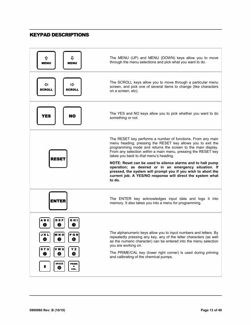
KEYPAD DESCRIPTIONS
The MENU (UP) and MENU (DOWN) keys allow you to move through the menu selections and pick what you want to do.
The RESET key performs a number of functions. From any main menu heading, pressing the RESET key allows you to exit the programming mode and returns the screen to the main display. From any selection within a main menu, pressing the RESET key takes you back to that menu’s heading.
NOTE: Reset can be used to silence alarms and to halt pump operation; as desired or in an emergency situation. If pressed, the system will prompt you if you wish to abort the current job. A YES/NO response will direct the system what
to do.
The ENTER key acknowledges input data and logs it into memory. It also takes you into a menu for programming. ENTER
MENU
MENU
The YES and NO keys allow you to pick whether you want to do something or not. YES NO
The SCROLL keys allow you to move through a particular menu screen, and pick one of several items to change (like characters on a screen, etc).
SCROLL
SCROLL
The alphanumeric keys allow you to input numbers and letters. By repeatedly pressing any key, any of the letter characters (as well as the numeric character) can be entered into the menu selection you are working on.
The PRIME/CAL key (lower right corner) is used during priming and calibrating of the chemical pumps.
A B C
D E F
G H I
J K L
M N O
P Q R
S T U
V W X
Y Z
█
SPACE
PRIME
CAL.
RESET

Page 14 of 40 0900960 Rev: B (10/10)
DISPLAY WINDOW
The main display window shows the status of chemical injections, and warns of any system error conditions that could cause potential problems with product delivery. To the left is an example of what the display might look like during typical operation.
– Top line: Left side shows the step number, which is a reference point for what the system is doing (i.e. pumping chemical, flushing, etc). Right side shows the job number, which is a reference to each product request.
– Second line: Shows the date and time when idle, otherwise will show what system activity is taking place, such as the status of a chemical injection in progress.
– Third line: Shows the most recent chemical request history. Number to the left shows the washer that requested chemical, followed by the chemical name and dosage pumped, then the time the job started.
– Bottom line: Same as above. New information is pushed down the list incrementally.
00 CHEM-TRAK JR 00 DATE 09/05 TIME 16:53:50 W3 BLEACH 010.0 OZ 16:51 W1 DETERG 025.0 OZ 16:47
HALT INDICATOR
FORMULA NUMBER DISPLAY
FORMULA SELECT
BUTTONS
NOTE: FE will display in the formula select window if there is a flush error
FORMULA SELECTOR(S)
TIP: Hold down on the formula select buttons to rapidly advance the number

0900960 Rev: B (10/10) Page 15 of 40
PROGRAMMING THE SYSTEM
Chem-Trak Jr. programming is done through the use of menu selections. Any menu can be entered by pressing the ENTER button, or exited by pressing RESET (or in some cases MENU or ). Its that simple! Each of the main menu headings give an idea of what information can be found, entered, or changed. Within each main menu selection are several screen ―prompts‖ that walk you through the complete programming process step-by-step.
From the main display screen, you must enter an access code to get into the programming menus. The Chem-Trak Jr. system has two access codes for protection:
The "main" access code, allows entry into ALL of the menus and functions of the system.
The "user" access code restricts access to only the Pump Prime Routines menu without the ability of changing
programmed information.
Systems are shipped from the factory with both access codes set to zero. Only a person with the "main" access code can change the "user" access code (changing codes is explained later in this manual). If desired the two access codes can be the same, however the user will then have access to ALL of the functions of the system, including the ability of changing programmed information.
IMPORTANT NOTES
It is recommended to clear memory prior to initial programming. See the MEMORY FUNCTIONS menu for details.
Programmed settings apply to all washers unless otherwise specified.
TO ENTER PROGRAMMING MODE...
To enter the programming mode, press the ENTER button on the keypad. The screen at left should appear. If the screen at left does not appear, wait 2 seconds, press RESET, then press ENTER again.
When you see the screen at left, type in the access code and press ENTER. Remember, for a new system, the access code will be zero (until you change it later).
ENTER ACCESS CODE
THEN PRESS ENTER
Disregard—this menu screen does not apply to EDP pumps.
00 00 00 00 00 00
00 00
ON TO PROGRAMMING MENUS

Page 16 of 40 0900960 Rev: B (10/10)
Clear pump volumes and delay times Restore default settings Clear sum/cycle report memory Set external memory module ID Clear external memory module
Change ID and main access code Set date and time Select unit of measure Setup auto formula select and auto formula reset Select load count pump Set delay time units/set signal lockout Setup flush parameters Set transfer time Set flush between status Set halt with injection
Change user access code Change report name Change formula names and weights Change chemical names and costs Set shift times and operating zone Set washer capacity Set signal qualifying time
Date dispenser installed Enable maintenance hold Prime pumps Calibrate pumps View pump flow rates Program formula dosages and delay times
Enable maintenance hold Prime pumps
MENU MAP
*** DISPENSER ***
MEMORY FUNCTIONS 1
*** DISPENSER ***
SETUP ROUTINES 2
*** DISPENSER ***
REPORT SETUP ROUTINES 3
*** DISPENSER ***
MAINTENANCE SCHEDULE 4
*** DISPENSER ***
PROGRAMMING ROUTINES 5
*** DISPENSER ***
PUMP PRIME ROUTINES 6

0900960 Rev: B (10/10) Page 17 of 40
This selection allows you to clear summary and cycle report memory. Press NO if you do not wish to clear sum/cycle information at this time. Press YES to clear the report memory.
A MUST WHEN YOU ARE READY TO TRACK WASHER AND CHEMICAL INFORMATION! Clearing the sum/cycle report clears:
– Production Summary Report
– Time Stamp Report (Wash Cycle Tracking)
CLEAR SUM/CYCLE REPORT ?
PRESS: YES OR NO
NO YES
This shows that report memory is being cleared. CLEARING ALL SUM/CYCLE
INFORMATION
This selection clears all formula pump volumes and delay times back to zero. Press NO if you do not wish to clear pump volumes at this time. Press YES for new installations, or when completely re-programming an existing system.
CLEAR PUMP VOLUMES ?
PRESS: YES OR NO
NO YES
If you entered YES, you are allowed to check and make sure that you really do want to clear pump volume information. Press NO if you are not sure that you want to clear all formula programming.
If you pressed YES, all volumes and delay times will then be cleared.
CLEARING ALL
VOLUMES AND DELAY TIMES
ARE YOU SURE ?
PRESS: YES OR NO
YES NO
Clear pump volumes and delay times Restore default settings Clear sum/cycle report memory Set external memory module ID Clear external memory module
*** DISPENSER ***
MEMORY FUNCTIONS 1
GO TO NEXT PAGE
This selection clears the setup parameters back to their default values. Press NO if you do not wish to restore default settings at this time. Press YES for new installations, or when completely re-programming an existing system.
RESTORE DEFAULT SETTINGS
PRESS: YES OR NO
NO YES
If you chose YES, the setup data is then cleared, and default settings are restored. When the clearing process is finished, you will then see the next menu selection.
CLEARING SETUP
*** PLEASE STAND BY ***

Page 18 of 40 0900960 Rev: B (10/10)
Continued *** DISPENSER ***
MEMORY FUNCTIONS 1
You are then asked if you really do want to use this command. Press YES if you are sure, or press NO to continue on to the next menu selection without setting the external memory module ID number.
When the process is complete, you will be returned back to the menu heading.
SETTING EXT MEM MODULE
*** ID TO CURRENT ID ***
ARE YOU SURE ?
PRESS: YES OR NO
YES NO
MEMORY FUNCTIONS MENU HEADING
This menu selection is used to synchronize the ID number of the external memory module to match the system’s ID.
Press NO for a new installation, or if the external memory module ID had been set previously. Press YES if you have changed the ID number in menu #2 (be sure the unit is not be multi-linked with other systems while performing this step).
NOTE: You will typically need to first set the ID number of the host, then come back to this menu later to set the ID number for the external memory module.
SET EXT MEM MODULE ID ?
PRESS: YES OR NO
NO YES
You are then asked if you really do want to use this command. Press YES if you are sure, or press NO to return back to the menu heading without clearing the external memory module.
When the process is complete, you will be returned back to the menu heading.
CLEARING MEMORY MODULE
************************
ARE YOU SURE ?
PRESS: YES OR NO
YES NO
This menu selection allows you to clear all time stamp data from the external memory module.
Press YES for a new installation, or if you wish to clear old data from the memory module that is no longer needed. Press NO if you do not wish to clear the memory module (or if you’re not sure) and you will return to the menu heading.
NOTE: While the memory module can hold a very large amount of data, it is recommended to periodically clear the module. Be sure that the old data is no longer needed before proceeding.
CLEAR MEMORY MODULE ?
PRESS: YES OR NO
NO YES

0900960 Rev: B (10/10) Page 19 of 40
Change ID and main access code Set date and time Select unit of measure Setup auto formula select and auto formula reset Select load count pump Set delay time units/set signal lockout Setup flush parameters Set transfer time Set flush between status Set halt with injection
*** DISPENSER ***
SETUP ROUTINES 2
This selection allows you to change the ID number of the system. The ID number is used for communication with a PC to print reports. It also identifies which host that a report was generated from when multiple systems are connected together in a daisy-chain format known as ―multi-linking‖.
Press NO if you do not wish to change the ID number at this time. Press YES to change the ID number (remember to go back to menu 1 and set the ID number of the external memory module).
NOTE: If two or more systems will be multi-linked together, they must have separate ID numbers. ID numbers should be set in increments of ten. For example, set the ID of the first unit to be 10, the second unit to be 20, the third to be 30, and so on.
CHANGE ID# ?
PRESS: YES OR NO
NO YES
If you pressed YES, you can now change the system’s ID number. Use the number keys to enter the new ID, then press ENTER. Press MENU to continue.
NEW CHEM-TRAK JR ID# 00
THEN PRESS ENTER
This selection allows you to change the ―main‖ access code. The main access code allows entry into to ALL menus and functions of the Chem-Trak Jr. Press NO if you do not wish to change the main access code at this time. Press YES to change the code.
CHANGE MAIN ACCESS CODE ?
PRESS: YES OR NO
NO YES
If you pressed YES, you can now change the system’s main access code. Pick a number that will be easy to remember. Use the number keys to enter the new code, then press ENTER. Press MENU to continue.
TIP: If the main access code is changed, keep a record of the change in a safe place (in the event that the code is forgotten). If the record of the code change becomes misplaced, contact Knight for help.
MAIN ACCESS CODE = 000
THEN PRESS ENTER
GO TO NEXT PAGE

Page 20 of 40 0900960 Rev: B (10/10)
This selection enables the Automatic Formula Select feature. This feature allows the washwheel controller to send signals to the slave and automatically select the correct wash formula. Washroom personnel no longer select formulas, thereby eliminating potential mistakes. Press 1 or 2 for the operation of your choice, then press MENU .
AUTO FORMULA SELECT OFF
1 = OFF 2 = ON
1 2
Press 1 if the machine is controlled by a chart or card reader, or 2 if the machine is controlled by a microprocessor. After the display shows your selection (CHART or MICRO), press MENU .
AUTO FORMULA MODE = MICRO
1 = CHART 2 = MICROPROCESSOR
1 2
This selection allows you to select the AFS qualifying time for MICRO mode (only). For a 1 second qualifying time, a 1 second signal equals formula 1, 2 seconds equals formula 2, 3 seconds equals formula 3, etc. For a 2 second qualifying time, a 2 second signal equals formula 1, 4 seconds equals formula 2, 6 seconds equals formula 3, etc. For a 5 second qualifying time, a 5 second signal equals formula 1, 10 seconds equals formula 2, 15 seconds equals formula 3, etc.
Press 1, 2, or 5, for the qualifying time of your choice, then press MENU .
AFS TIME = 1 SEC
1=1SEC 2=2SEC 5=5SEC
1 2 5
Continued *** DISPENSER ***
SETUP ROUTINES 2
This selection allows you to change the current date and time (as shown on the main display screen). Press NO if you do not wish to change the date and time. Otherwise press YES.
SET DATE & TIME ?
PRESS: YES OR NO
NO YES
Use number buttons to set date and time (military format, 13:00 = 1:00 PM) then press ENTER. Press the MENU button to move on to the next menu selection.
HOUR 00 MINUTE 00
MONTH 00 DAY 00 YR 00
This selection allows you to choose between US, Metric, or Imperial units of measure. Use the keys to choose the correct setting, then use MENU to move through this menu selection.
UNIT OF MEASURE = US
1=US 2=METRIC 3=IMPERIAL
GO TO NEXT PAGE

0900960 Rev: B (10/10) Page 21 of 40
AUTO FORMULA SELECT — HOW IT WORKS
MICRO MODE: This is used for Automatically Selecting Formulas with washwheels that have microprocessor controllers.
Only SIB inputs 11 - 13 can be used for micro mode AFS. Input 11 does not add any numbers to the formula selected. Input 12 adds the number 30, and input 13 adds the number 60 to the formula, regardless of the AFS qualifying time. For example a 20 second signal using input 11 would result in formula 20 being selected, whereas a 20 second signal to input 12 would result in formula 50 being selected, and so on.
To operate Micro Mode Automatic Formula Select, choose an available signal output from the microprocessor that will be dedicated to selecting formulas. Connect the signal from that output to the Automatic Formula Select input you wish to use (11, 12, or 13). For a micro processor controlled machine, to change formulas, the FIRST signal to come from the controller must be on the Automatic Formula Select input line. The length of time this signal is applied (based on the AFS time setting) will determine the selected formula.
CHART MODE: This is used for automatically selecting formulas for washers with cards or charts to control the wash formula.
The Automatic Formula Select signal input will be pump 11 (only) on the SIB. Signal inputs 1 - 7 are used for adding up the correct formula number.
To operate Chart Mode Automatic Formula Select, choose an available signal track on the chart or card that will be dedicated to selecting formulas. Connect the signal from that track to the Automatic Formula select input you designated.
The FIRST cut in the chart or card must be on the Automatic Formula Select Signal track. Thirty seconds after this cut begins, the dispenser will ―look‖ at signal inputs 1 through 7 and evaluate the formula number selected (any signal combination higher than 90 will revert the system to formula 90).
The formula selector display will acknowledge the correct formula. Once the formula select process is finished, pump input signals return to normal operation. All pump signals must turn off for a minimum of five seconds, then retriggered for a pump to operate.
Example: the chart cuts below would automatically select formula #9 after 30 seconds.
CHART/CARD DIRECTION
███ SIB PUMP #1 SIGNAL INPUT > ADD 1
SIB PUMP #2 SIGNAL INPUT > ADD 2
SIB PUMP #3 SIGNAL INPUT > ADD 4
███ SIB PUMP #4 SIGNAL INPUT > ADD 8
SIB PUMP #5 SIGNAL INPUT > ADD 16
SIB PUMP #6 SIGNAL INPUT > ADD 32
SIB PUMP #7 SIGNAL INPUT > ADD 64
██████ SIB INPUT #11 AUTO FORMULA SELECT SIGNAL
Continued *** DISPENSER ***
SETUP ROUTINES 2
GO TO NEXT PAGE

Page 22 of 40 0900960 Rev: B (10/10)
This sets which pump is being used to count loads. Always enter the last pump in the system that will receive a signal. When a cycle is run, the last pump ―stamps‖ the timing data into memory (for reports and other purposes). Enter the number of the load count pump and press ENTER. Press MENU to continue.
NOTE: The load count pump must be signaled on every formula for proper wash cycle tracking data. When the load count pump is signaled, all volume levels for that formula are reset to level 1. This setting applies to all washers using the Chem-Trak Jr.
CHOOSE LOAD COUNT
PUMP # 00 PRESS ENTER
If enabled, this feature resets the formula number to 00 after the load count pump activates. In cases where automatic formula select is OFF (formulas selected manually), this feature ensures that an operator cannot wash a load with the wrong formula. When a washcycle is finished, the next formula must be manually chosen. Make your selection, then press MENU to continue.
AUTO FORM RESET DISABLE
1=ENABLED 2=DISABLED
1 2
This selection allows you to choose the delay unit of measure. Some signals only need to be delayed for a few seconds (i.e. to avoid dumping chemical onto dry linen), others may need longer delay times. Select the delay time unit of measure, then press MENU to continue.
DELAY TIME UNITS = SEC
1 = MINUTES 2 = SECONDS
1 2
This feature helps prevent unwanted injections that are caused by ―erroneous‖ signals from the washer (example: when the water level goes low and a fill valve activates). Make your selection, then press MENU to continue.
5 MIN SIGNAL LOCKOUT OFF
1= OFF 2= ON
1 2
This sets the time the flush solenoid will activate after the pumps have finished. Type in the flush time (range is 10 - 99 seconds) required to clear the chemical from the tube, then press ENTER. Press MENU to move on to the next menu.
TIP: Flush time should be set long enough to completely clear chemical from the delivery tube. Determine this setting based on the thickest product that will be used. This setting is particularly important if using the ―flush between pumps‖ option.
WATER FLUSH TIME
= 40 SECONDS
Continued *** DISPENSER ***
SETUP ROUTINES 2
GO TO NEXT PAGE

0900960 Rev: B (10/10) Page 23 of 40
This selection sets the amount of time that the diverter solenoid will activate, after the flush time expires, to deliver product to the washer. Type in the washer number and transfer time (range is 0 - 99 seconds) then press ENTER. Repeat for each washer in use. Press MENU to continue.
TIP: The transfer time should be set long enough to deliver all chemicals to each respective washer (based on washer distance and product viscosity). Determine this setting based on the thickest product that will be used.
TRANSFER TIME
WASHER 1 25 SECONDS
The system has a flow switch that is used to verify actual water flow. This setting tells the system at what point during the flush cycle to check the flow switch state (open or closed). It is recommended that this setting be no less than 05 seconds. Make your selection and press ENTER. Press MENU to continue.
If deemed necessary by the customer, the delay can be set to 00 which will turn this feature ―off‖, and the flow switch input will not be checked (and therefore no FLUSH ERROR warnings will be produced). The customer accepts liability in such cases, as the system will not be able to detect flush errors.
NOTE: The flush solenoid will start before the pump. After the flush error delay time, if water flow is good, the pump will start. If water flow is bad, a flush error will occur and the system will stop. In this case, no chemical residue will be left in the flush manifold.
FLUSH ERROR DELAY
= 05 SECONDS
This selection sets an additional amount of time that will be added to the normal flush time during transfer. Each pump can have its own flush time if desired (range is 0 - 99 seconds). The purpose of this setting is to add extra flush time for pumps that have very viscous products. This helps to ensure that no chemical residue is left in the flush line.
NOTE: If two (or more) pumps run together and each one has a flush time, then the longest flush time will be used during transfer.
PUMP FLUSH TIME
PUMP 01 00 SECONDS
Continued *** DISPENSER ***
SETUP ROUTINES 2
GO TO NEXT PAGE
This selection allows you to choose if the system will add flush water between chemical injections before transferring all chemicals to the washer. This provides a barrier of water between non-compatible chemicals in situations where the washer calls for multiple chemicals at the same time.
Make your choice, then press MENU to continue.
FLUSH BETWEEN PUMPS = OFF
1 = OFF 2 = ON
1 2

Page 24 of 40 0900960 Rev: B (10/10)
SETUP ROUTINES MENU HEADING
This feature allows the SIB to pause the washer’s operation (halt) while its own chemical injection is taking place. This can be helpful in the following applications:
– Excessive pump run time (due to product viscosity, pump size).
– Far distance to the washer (longer flush and transfer times).
– Low water pressure.
The Chem-Trak SIB has special relay contacts that can be connected to the washer’s controls to halt machine operation. Even if this feature is turned off, the SIB will still halt the washer if requesting chemical while the system is busy feeding other washers. Make your selection, then press MENU to continue.
HALT W/INJECTION = OFF
1= ON 2= OFF
1 2
Disregard — for future use (leave setting on DISABLED). Press MENU to return to the menu heading.
LEVEL SENSORS = DISABLED
1 = ENABLED 2 = DISABLED
1 2
Continued *** DISPENSER ***
SETUP ROUTINES 2

0900960 Rev: B (10/10) Page 25 of 40
This selection allows you to change the user access code. The user access code allows access to only the pump prime menu of the Chem-Trak Jr. and allows printing-only when using WinReporter PC software. Pressing NO allows you to move through this menu selection.
CHANGE USER ACCESS CODE?
PRESS: YES OR NO
NO YES
If you entered YES, you will be prompted for a new user access code. Use the keys to enter the new data, and press ENTER when done. Press MENU to move through the menu selection.
USER ACCESS CODE = 000
THEN PRESS ENTER
The report name is what is printed on the report heading. Pressing NO allows you to move through this menu selection.
CHANGE REPORT NAME ?
PRESS: YES OR NO
NO YES
If you entered YES, you can change the report name (use the SCROLL and lettered keys to enter the new data, and press ENTER when done). Press MENU when finished to move through this menu selection.
TIP: Entering the report name in the center of the display window will center it at the top of the report.
▓
Change user access code Change report name Change formula names and weights Change chemical names and costs Set shift times and operating zone Set washer capacity Set signal qualifying time
*** DISPENSER ***
REPORT SETUP ROUTINES 3
GO TO NEXT PAGE

Page 26 of 40 0900960 Rev: B (10/10)
This menu selection allows you to change the formula names and load weight for each formula. Giving each formula a descriptive name makes the system more user-friendly. Load weights are used for data-tracking purposes to generate reports. Pressing NO allows you to move through this menu selection.
CHANGE FORMULA NAME AND
WEIGHT? PRESS: YES OR NO
NO YES
If you entered YES, you will first change the formula names. When finished changing all formula names, press MENU to move on to the next display for changing load weights.
TIP: First select the formula number on the top line and press ENTER...the current formula name will appear on the bottom line. Then change the name on the bottom line and press ENTER again to lock-in the new data.
FORMULA 01
FORMULA 01
Now enter the load weight for each formula used. When finished changing load weights, press MENU to move on to the next menu selection.
TIP: First select the formula number on the top line and press ENTER...the current load weight will appear on the bottom line. Then change weight on the bottom line and press ENTER again to lock-in the new data.
FORMULA 01
LOAD WEIGHT 000 LBS
*** DISPENSER ***
REPORT SETUP ROUTINES 3 Continued
GO TO NEXT PAGE
This is the type of chemical for each pump on the system. Pressing NO allows you to move through this menu selection.
CHANGE CHEMICAL NAMES
PRESS: YES OR NO
NO YES
If you entered YES, you can change the chemical name for each pump (using the SCROLL and lettered keys to enter the new data). Press MENU to move through this menu selection.
TIP: First select the pump number on the top line and press ENTER...the current name for the pump you selected will be displayed on the bottom line. Then change the information on the bottom line and press ENTER again to lock-in the new pump name.
PUMP 01
PUMP-01

0900960 Rev: B (10/10) Page 27 of 40
This selection allows you to enter the shift times (the start time for each work shift in the washroom) for the report. Pressing NO allows you to move through this menu selection.
WANT TO SET SHIFT TIMES ?
PRESS: YES OR NO
NO YES
If you entered YES, you can change the start time for each washroom work shift. Use SCROLL and the numbered keys to enter the new data, then press ENTER. Shift times are entered on a 24 hour clock cycle (like military time). Press MENU to continue.
START TIMES #1 06:00
#2 11:00 #3 17:00
*** DISPENSER ***
REPORT SETUP ROUTINES 3 Continued
This menu selection allows you to change costs for each product. Pressing NO allows you to move through this menu selection.
CHANGE PRODUCT COSTS ?
PRESS: YES OR NO
NO YES
If you entered YES, you can change the cost for each chemical (using the SCROLL and number keys to enter the new data). Press MENU to move through this menu selection.
TIP: First select the pump number on the left side of the display and press ENTER...the product cost for the pump you selected will be displayed on the right side. Then change the information on the right side and press ENTER again to lock-in the new product cost.
PUMP 01 $00.00 /GALS
Disregard—this menu screen does not apply to EDP pumps.
SQUEEZE TUBE WARNING
= 00 %
GO TO NEXT PAGE
Page 28 of 40 0900960 Rev: B (10/10)
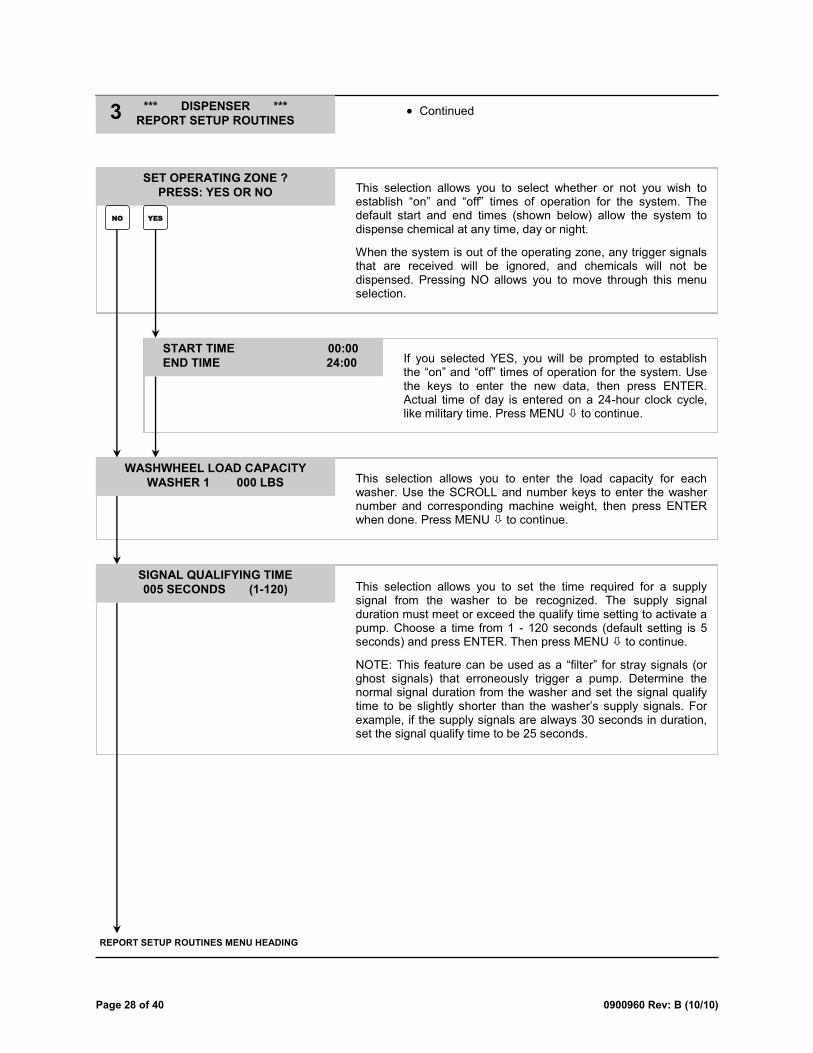
This selection allows you to select whether or not you wish to establish ―on‖ and ―off‖ times of operation for the system. The default start and end times (shown below) allow the system to dispense chemical at any time, day or night.
When the system is out of the operating zone, any trigger signals that are received will be ignored, and chemicals will not be dispensed. Pressing NO allows you to move through this menu selection.
SET OPERATING ZONE ?
PRESS: YES OR NO
NO YES
If you selected YES, you will be prompted to establish the ―on‖ and ―off‖ times of operation for the system. Use the keys to enter the new data, then press ENTER. Actual time of day is entered on a 24-hour clock cycle, like military time. Press MENU to continue.
START TIME 00:00
END TIME 24:00
This selection allows you to enter the load capacity for each washer. Use the SCROLL and number keys to enter the washer number and corresponding machine weight, then press ENTER when done. Press MENU to continue.
WASHWHEEL LOAD CAPACITY
WASHER 1 000 LBS
REPORT SETUP ROUTINES MENU HEADING
This selection allows you to set the time required for a supply signal from the washer to be recognized. The supply signal duration must meet or exceed the qualify time setting to activate a pump. Choose a time from 1 - 120 seconds (default setting is 5 seconds) and press ENTER. Then press MENU to continue.
NOTE: This feature can be used as a ―filter‖ for stray signals (or ghost signals) that erroneously trigger a pump. Determine the normal signal duration from the washer and set the signal qualify time to be slightly shorter than the washer’s supply signals. For example, if the supply signals are always 30 seconds in duration, set the signal qualify time to be 25 seconds.
SIGNAL QUALIFYING TIME
005 SECONDS (1-120)
*** DISPENSER ***
REPORT SETUP ROUTINES 3 Continued

0900960 Rev: B (10/10) Page 29 of 40
Date dispenser installed *** DISPENSER ***
MAINTENANCE SCHEDULE 4
This selection allows you to enter the date that the system was installed. (Use the SCROLL and number keys to enter the new data, and press ENTER when done). Press MENU to move thru this menu selection.
DISPENSER INSTALLED
00/00/00
MAINTENANCE SCHEDULE MENU HEADING
Disregard—this menu screen does not apply to EDP pumps.
SQUEEZE TUBES CHANGED
PUMP 01 00/00/00
Disregard—this menu screen does not apply to EDP pumps.
SQUEEZE TUBES LAST LUBED
PUMP 01 00/00/00

Page 30 of 40 0900960 Rev: B (10/10)
Enable maintenance hold Prime pumps Calibrate pumps View pump flow rates Program formula dosages and delay times
*** DISPENSER ***
PROGRAMMING ROUTINES 5
GO TO NEXT PAGE
This allows you to prime chemical pumps (necessary for proper calibration). Choose YES or NO to continue.
PRIME PUMPS ?
PRESS: YES OR NO
NO YES
Choose the washer that you want product sent to during the priming process, then press ENTER.
SEND PRODUCT TO WASHER
PRESS ENTER 1
Choose the pump you wish to prime, then use the PRIME/CAL button to start and stop the pump.
You can choose if you wish to transfer the product to the selected washer at this time. Choose YES or NO.
PRIME PUMP 01
PUSH PRIME TO START/STOP
TRANSFER TO WASHER ?
PRESS: YES OR NO
NO YES
Disregard — for future use. EMPTYING VESSEL
Chemical will transfer to the washer and the display will count down the remaining time till the process is finished. The count down is a sum of flush time, and transfer time and will be activated in this order.
TRANSFERRING-WASHER1 060
This display shows that the system is on maintenance hold. If a feed request is received, the washer will be halted (by the SIB) and the request will be put in the queue for later delivery. Press RESET to end the hold and resume normal operation. Or press MENU to advance to the next step and continue the hold.
This feature allows you to halt the washers and chemical feed while performing maintenance. Choose YES or NO to continue (if ―SYSTEM BUSY‖ appears, wait 30 seconds then try again).
ENABLE MAINTENANCE HOLD ?
PRESS: YES OR NO
NO YES
MAINTENANCE HOLD ENABLED
HIT RESET KEY TO RESUME
0900960 Rev: B (10/10) Page 31 of 40
Continued *** DISPENSER ***
PROGRAMMING ROUTINES 5
GO TO NEXT PAGE
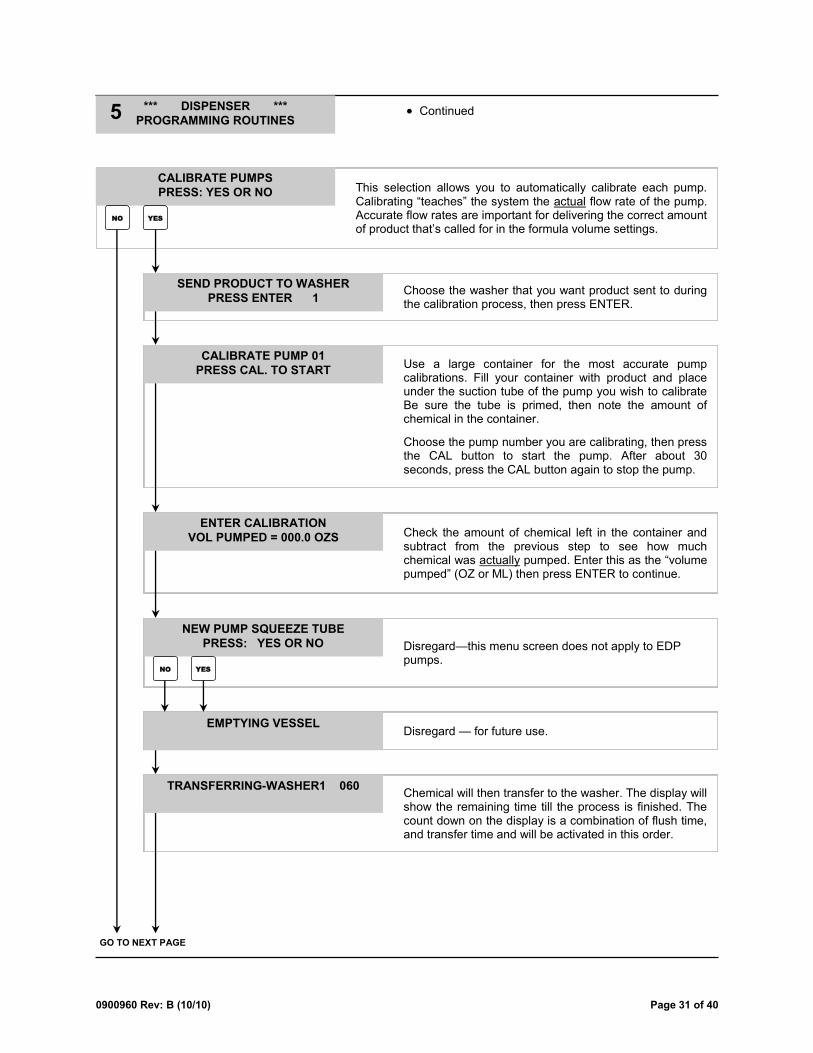
Use a large container for the most accurate pump calibrations. Fill your container with product and place under the suction tube of the pump you wish to calibrate Be sure the tube is primed, then note the amount of chemical in the container.
Choose the pump number you are calibrating, then press the CAL button to start the pump. After about 30 seconds, press the CAL button again to stop the pump.
CALIBRATE PUMP 01
PRESS CAL. TO START
Check the amount of chemical left in the container and subtract from the previous step to see how much chemical was actually pumped. Enter this as the ―volume pumped‖ (OZ or ML) then press ENTER to continue.
ENTER CALIBRATION
VOL PUMPED = 000.0 OZS
This selection allows you to automatically calibrate each pump. Calibrating ―teaches‖ the system the actual flow rate of the pump. Accurate flow rates are important for delivering the correct amount of product that’s called for in the formula volume settings.
CALIBRATE PUMPS
PRESS: YES OR NO
NO YES
Disregard—this menu screen does not apply to EDP pumps.
Disregard — for future use. EMPTYING VESSEL
Chemical will then transfer to the washer. The display will show the remaining time till the process is finished. The count down on the display is a combination of flush time, and transfer time and will be activated in this order.
TRANSFERRING-WASHER1 060
NEW PUMP SQUEEZE TUBE
PRESS: YES OR NO
NO YES
Choose the washer that you want product sent to during the calibration process, then press ENTER.
SEND PRODUCT TO WASHER
PRESS ENTER 1

Page 32 of 40 0900960 Rev: B (10/10)
For US and Imperial units of measure, formula volume settings are programmed in ounces only (the max
allowed is 999.9 ounces). For Metric units of measure, formula volume settings are programmed in milliliters only (the max allowed is 9999 milliliters).
The maximum run time for any pump is 255 seconds. If a formula volume is programmed that will cause a
pump to exceed 255 seconds (base on that pump’s flow rate) the pump will not activate when signaled.
Delay times can be used when washer signals do not occur at optimum times for chemical dispensing.
Maximum delay times are 255 seconds or minutes. Selection of seconds or minutes is done in the Dispenser Setup Routines menu.
Pumped volumes of up to 4095.9 ounces, or 40959 milliliters will be printed on the cycle report. Pumped
volumes over this amount will result in the symbols *VOL? appearing on the cycle report.
This menu selection allows you to enter pump volumes and delay times for the formulas you will use. The system is capable of 90 total formulas. You can decide how you want to use the formulas. For example, you can program all 90 formulas to be shared by all washers. Or you can program certain ―groups‖ of formulas to be used by only certain washers (such as formulas 1 - 20 for washer 1, formulas 21 - 40 for washer 2, etc). When finished programming, press MENU to move on to the next menu.
TIP: This selection can be used to simply review programmed formula settings. By entering the formula number, volume level, and pump number, and then pressing ENTER, the programmed volume and delay time will be displayed.
TIP: To change the programmed information, first select the formula number, volume level, and pump number on the top line and press ENTER (as mentioned above)...the current settings will be displayed on the bottom line. Then change the information on the bottom line and press ENTER again to lock-in the new data.
FORM 01 LEVEL 1 PUMP 01
VOL 000.0 OZS DELAY 000
Continued *** DISPENSER ***
PROGRAMMING ROUTINES 5
The system calculates the flow rate of the pump and then displays the result. To the left is an example of what a flow rate might look like (the MLU number is for reference only by Knight personnel). Press MENU to calibrate another pump or press MENU to continue.
NOTE: You can manually enter or change the flow rates if necessary. Use the PRIME/CAL button to alternate OZ/GAL, or ML/L.
FLOW RATES / MIN
P-01 38.6 OZS 0275MLU
This menu selection allows you to view existing pump calibrations. Choose YES or NO to continue.
VIEW PUMP CALIBRATION
PRESS: YES OR NO
YES NO
PROGRAMMING ROUTINES MENU HEADING

0900960 Rev: B (10/10) Page 33 of 40
Enable maintenance hold Prime pumps
*** DISPENSER ***
PUMP PRIME ROUTINES 6
PRIME ROUTINES MENU HEADING
Disregard — for future use. Press NO to continue. FLUSH VESSEL TO DRAIN
PRESS: YES OR NO
Choose the pump you wish to prime, then use the PRIME/CAL button to start and stop the pump.
You can choose if you wish to transfer the product to the selected washer. Choose YES or NO.
This menu allows you to prime the chemical pumps. Choose YES or NO to continue.
Choose the washer that you want product sent to during the priming process and press ENTER.
SEND PRODUCT TO WASHER
PRESS ENTER 1
PRIME PUMPS ?
PRESS: YES OR NO
NO YES
PRIME PUMP 01
PUSH PRIME TO START/STOP
TRANSFER TO WASHER ?
PRESS: YES OR NO
NO YES
Disregard — for future use. EMPTYING VESSEL
Chemical will transfer to the washer and the display will count down the remaining time till the process is finished. The count down is a sum of flush time and transfer time and will be activated in this order.
TRANSFERRING-WASHER1 060
This display shows that the system is on maintenance hold. If a feed request is received, its washer will be halted (by the SIB or Interrupt Module) and the request will be put in the queue for later delivery. Press RESET to end the hold and resume normal operation. Or press MENU to advance to the next step
This feature allows you to halt the washers and chemical feed while performing maintenance. Choose YES or NO to continue (if ―SYSTEM BUSY‖ appears, wait 30 seconds then try again).
ENABLE MAINTENANCE HOLD ?
PRESS: YES OR NO
NO YES
MAINTENANCE HOLD ENABLED
HIT RESET KEY TO RESUME

Page 34 of 40 0900960 Rev: B (10/10)
MAINTENANCE
Good maintenance habits are key to getting the best performance out of your equipment. The following service items are recommended for normal operation. The intervals may vary depending on chemical affect and actual usage.
NOTE: There is a 3-way valve on the output side of the flush manifold that is provided for servicing. This valve relieves pressure from the manifold for changing checkvalves or any other plumbed manifold part.
Service: Replace manifold checkvalves.
Interval: 3 times a year, or as needed.
(1) Bleed any pressure from discharge line.
(2) Disconnect chemical line from barb fitting.
(3) Remove checkvalve from manifold by turning it counter-clockwise.
(4) Wrap the threads of the new checkvalve with plumbing tape (2 - 3 turns) and install into the manifold being careful not to over-tighten.
(5) Re-connect chemical line to barb fitting.

0900960 Rev: B (10/10) Page 35 of 40
TROUBLESHOOTING
Formula selector does not light up - no power:
Check fuses — replace if necessary.
Check for loose wiring connections.
Check voltage at main connection — refer to wiring
diagram.
Pumps do not trigger from signals:
Check signal voltage and duration.
Check for flush error — press RESET to clear.
Check pump volume and delay time settings.
Pump may be counting down a "lockout" time (if used)
from a previous activation.
Pump may be trying to skip a level.
Pump flow rate not set, or incorrect
Pumps will not activate when trying to prime, or during a washcycle:
Check for loose pump motor wires.
Check for voltage from circuit board to motor.
Check for mechanical binding of moving parts.
Pumps run but do not dispense product:
Check product containers.
Check for air leaks on suction line.
Check for blockage from pump into the checkvalve on
the flush manifold.
Pumps trigger more than once during cycle:
Check supply signal input for repeat signals from
washmachine.
Check signal lock-out function.
Flush errors keep occurring:
Check to see if a flush manifold is operating correctly.
Check flow switch for proper connection to CIO board.
Check for adequate water flow (clean debris from filter
screen at water inlet).
Check flush error delay setting and adjust if needed.
Press RESET to clear flush errors — pumps will not
run during flush error.
Flush solenoid does not open:
Check for loose wire connections to CIO board.
Check for adequate water pressure.
Check for obstruction inside solenoid.
Check condition of diaphragm inside solenoid.

Page 36 of 40 0900960 Rev: B (10/10)
PARTS DIAGRAM — PUMP CABINET

0900960 Rev: B (10/10) Page 37 of 40
PARTS DIAGRAM — CONTROLLER & POWER SUPPLY

Page 38 of 40 0900960 Rev: B (10/10)
PARTS DIAGRAM — MANIFOLD & STANDARD DIVERTER
0900960 Rev: B (10/10) Page 39 of 40
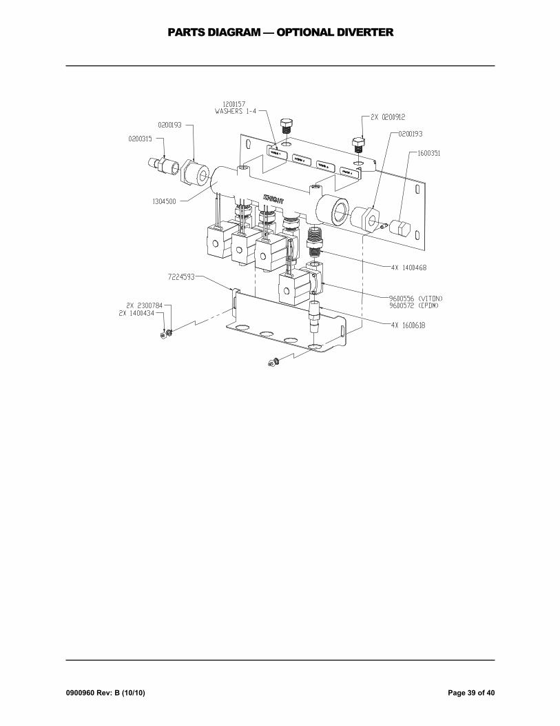
PARTS DIAGRAM — OPTIONAL DIVERTER

Page 40 of 40 0900960 Rev: B (10/10)
DISCLAIMER
Knight LLC does not accept responsibility for the mishandling, misuse, or non-performance of the described items when used for purposes other than those specified in the instructions. For hazardous materials information consult label, MSDS, or Knight LLC. Knight products are not for use in potentially explosive environments. Any use of our equipment in such an environment is at the risk of the user, Knight does not accept any liability in such circumstances.
WARRANTY
All Knight controls and pump systems are warranted against defects in material and workmanship for a period of ONE year. All electronic control boards have a TWO year warranty. Warranty applies only to the replacement or repair of such parts when returned to factory with a Knight Return Authorization (KRA) number, freight prepaid, and found to be defective upon factory authorized inspection. Bearings and pump seals or rubber and synthetic rubber parts such as ―O‖ rings, diaphragms, squeeze tubing, and gaskets are considered expendable and are not covered under warranty. Warranty does not cover liability resulting from performance of this equipment nor the labor to replace this equipment. Product abuse or misuse voids warranty.
FOOTNOTE
The information and specifications included in this publication were in effect at the time of approval for printing. Knight LLC reserves the right, however, to discontinue or change specifications or design at any time without notice and without incurring any obligation whatsoever.
Knight Headquarters Tel: 949.595.4800 Fax: 949.595.4801
USA Toll Free Tel: 800.854.3764 Fax: 800.752.9518
Knight Canada Tel: 905.542.2333 Fax: 905.542.1536
Knight Europe Tel: 44.1293.615.570 Fax: 44.1293.615.585
Knight Australia Tel: 61.2.9725.2588 Fax: 61.2.9725.2025
Knight N. Asia Tel: 82.2.3481.6683 Fax: 82.2.3482.5742
Knight S. Asia Tel: 65.6763.6633 Fax: 65.6764.4020
KNIGHT LLC, A Unit of IDEX Corporation (www.knightequip.com)