Embed Size (px)
Citation preview
�www.JournalofKneeSurgery.com
ABSTRACT: This article examines how the relation-ship between sagittal and coronal anatomy, anterior cruciate ligament (ACL) graft dimensions, and tibial and femoral tunnel placement affects the posterior cru-ciate ligament (PCL) and roof impingement, and their undesirable clinical consequences of motion loss and instability. Based on these interrelationships, a variety of checkpoints are defined that can be used intraop-eratively to determine whether placement of the tibial tunnel guidewire avoids PCL and roof impingement, and whether placement of the femoral tunnel guide-wire avoids PCL impingement with either transtibial or transportal techniques. A simple, 3-dimensional tibial drill guide that consistently places the tibial tun-nel correctly without PCL and roof impingement so the femoral tunnel, when drilled through the tibial tunnel, restores the normal tension pattern in the ACL graft also is described. Arthroscopic and radiographic checkpoints that assess the final placement of the ACL graft and tibial and femoral tunnels are discussed.
[J Knee Surg. 2009;22:xxx-xxx.]
IntroductIon
The most important predictor of clinical outcome in anterior cruciate ligament (ACL) reconstruction is tunnel placement. The 3 criteria that define correctly placed tun-nels in any ACL reconstruction are: 1) the avoidance of posterior cruciate ligament (PCL) impingement, which re-
stores flexion while maintaining stability11,18; 2) the avoid-ance of roof impingement, which restores extension while maintaining stability1,3,4,6-10,13,14,19; and 3) the matching of the tension pattern in the graft to the intact ACL, which avoids high joint contact pressures throughout the motion arc.18 Small errors in tunnel placement result in loss of flexion, loss of extension, stiffness, instability, pain, and prolonged recovery. These complications are all prevent-able by correctly judging guidewire placement intraopera-tively with the use of reliable arthroscopic, radiographic, and topographic checkpoints. This article reviews the in-terrelationship between sagittal and coronal anatomy and ACL graft dimensions, and then defines arthroscopic, ra-diographic, and topographic checkpoints that can be used intraoperatively to avoid PCL and roof impingement and restore the tension pattern in the ACL graft to normal.
tunnel Placement In tHe coronal Plane and Pcl ImPIngement
Correct placement of the tibial and femoral tunnel in the coronal plane prevents the complications caused by PCL impingement, which are loss of flexion and instabil-ity.2,11,18 With the transtibial technique, PCL impingement occurs when the tibial tunnel is too medial and vertical, which also makes the femoral tunnel too vertical as the femoral tunnel is drilled through the tibial tunnel.11,16-18 With the anteromedial portal technique, PCL impinge-ment occurs when the tibial tunnel is too medial or the femoral tunnel is too vertical. Posterior cruciate ligament impingement results from any of the tibial and femoral tunnel placement combinations that allow the ACL graft to impinge or wrap around the PCL before the knee reach-es terminal flexion. Posterior cruciate ligament impinge-ment is characterized by higher tension in the ACL graft than in the intact ACL during knee flexion.18
Impingement between the ACL graft and PCL creates
Checkpoints for Judging Tunnel and Anterior Cruciate Ligament Graft Placement
Stephen M. Howell, MD Maury L. Hull, PhD
Drs Howell and Hull are from the Department of Mechanical Engi-neering, and Dr Hull is also from the Biomedical Engineering Program, University of California, Davis, Calif.
Correspondence: Stephen M. Howell, MD, Department of Mechani-cal Engineering, One Shields Ave, University of California, Davis, CA 95616.
�
THE JOURNAL OF KNEE SURGERY
April 2009 / Vol 22 No 2
problems in the knee with patients either not regaining full flexion or regaining full flexion after a protracted recovery slowed by gradual elongation of the graft from stretching around the PCL.11,18 Accordingly, several checkpoints are used to prevent PCL impingement, which include assess-ing and widening the space between the lateral femoral condyle and the PCL, assessing the relationship of the tibial tunnel guidewire with respect to the base of the PCL and the tip of the lateral spine or eminence, and assessing the relationship of the guidewire to the medial joint line of the tibia with the knee in 90° of flexion.
The cross-sectional dimension and orientation of the ACL graft (ie, round soft-tissue graft or rectangular bone plug graft) determines the distance between the center of the tibial tunnel and the tip of the lateral tibia spine. For a 9-mm diameter soft-tissue graft, which has a round cross-sectional area, the distance between the tip of the lateral tibia spine and the center of the guidewire should be 5 mm. For a 10-mm wide and 4-mm thick bone-patellar ten-don-bone graft, which has a rectangular cross-sectional area, the distance between the tip of the lateral tibia spine and the guidewire depends on the direction the cortical surface of the bone plug faces within the tibial tunnel. If the cortical surface of the bone plugs faces anterior, pos-terior, or lateral, then the distance between the tip of the lateral tibia spine and guidewire should be 5 mm. If the cortical surface faces medial and an interference screw is placed lateral to the bone plug, then the distance between the tip of the lateral tibia spine and the guidewire could be as little as 0 mm.
tIbIal tunnel cHeckPoInts for elImInatIng Pcl ImPIngement
Widening the NotchThe first step to avoid PCL impingement, which ap-
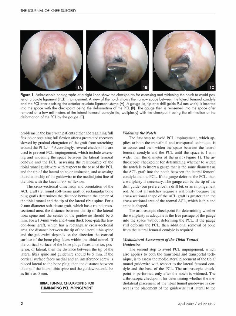
plies to both the transtibial and transportal technique, is to assess and then widen the space between the lateral femoral condyle and the PCL until the space is 1 mm wider than the diameter of the graft (Figure 1). The ar-throscopic checkpoint for determining whether to widen the notch is to insert a gauge that is the same diameter as the ACL graft into the notch between the lateral femoral condyle and the PCL. If the gauge deforms the PCL, then a wallplasty is necessary. The gauge can be the tip of the drill guide (our preference), a drill bit, or an impingement rod. Almost all notches require a wallplasty because the cross-sectional shape of the ACL graft is greater than the cross-sectional area of the normal ACL, which is thin and spindle-shaped.
The arthroscopic checkpoint for determining whether the wallplasty is adequate is the free passage of the gauge into the space without deforming the PCL. If the gauge still deforms the PCL, then additional removal of bone from the lateral femoral condyle is required.
Mediolateral Assessment of the Tibial Tunnel Guidewire
The second step to avoid PCL impingement, which also applies to both the transtibial and transportal tech-nique, is to assess the mediolateral placement of the tibial tunnel guidewire with respect to the lateral femoral con-dyle and the base of the PCL. The arthroscopic check-point is performed only after the notch is widened. The arthroscopic checkpoint for determining whether the me-diolateral placement of the tibial tunnel guidewire is cor-rect is the placement of the guidewire just lateral to the
1A
figure �. Arthroscopic photographs of a right knee show the checkpoints for assessing and widening the notch to avoid pos-terior cruciate ligament (PCL) impingement. A view of the notch shows the narrow space between the lateral femoral condyle and the PCL after excising the anterior cruciate ligament stump (A). A gauge (ie, tip of a drill guide 9.5-mm wide) is inserted into the space with the checkpoint being the deformation of the PCL (B). The gauge then is reinserted into the space after removal of a few millimeters of the lateral femoral condyle (ie, wallplasty) with the checkpoint being the elimination of the deformation of the PCL by the gauge (C).
1B 1C
�
Tunnel & ACL Graft Placement
www.JournalofKneeSurgery.com
base of the PCL (Figure 2A). If the guidewire passes over the base of the PCL, then the guidewire is too medial.
The radiographic checkpoint for determining the me-diolateral placement is the lateral edge of the tibial tun-nel passing through the tip of the lateral tibial spine or eminence. This assessment is best made by projecting the walls of the tibial tunnel on the center of the guidewire (Figure 2B). If the projection of the medial edge of the tibial tunnel passes through or medial to the tip of the me-dial spine, then the tibial tunnel is too medial, resulting in PCL impingement.
Angular Assessment of the Tibial Tunnel Guidewire in the Coronal Plane
The third step to avoid PCL impingement, which ap-plies primarily to the transtibial technique, is to assess the trajectory of the tibial tunnel guidewire with respect to the arc of the notch and with respect to the medial joint line of the tibia. The topographic checkpoint for determining whether the angular placement of the tibial tunnel guide-wire is correct is the starting point for drilling the guide-wire must be within the body of the medial collateral liga-ment. If the starting point of the guidewire is anterior to the medial collateral ligament, then the tibial tunnel is too vertical and the femoral tunnel will be drilled too close to the PCL, resulting in PCL impingement.
The arthroscopic checkpoint for determining whether the angular placement of the tibial tunnel guidewire is cor-rect is the tip of the guidewire must bisect an arc running from the apex to the base of the notch (Figure 2A). If the trajectory of the tip of the guidewire is within the medial
half of the arc, then the tibial tunnel is too vertical and the femoral tunnel will cause PCL impingement.
The radiographic checkpoint for determining whether the angular placement of the tibial tunnel guidewire is correct is the formation of a 60° to 65° angle between the tibial tunnel guidewire and the medial joint line (Figure 2C).11,15-18 If the angle is >70°, then the femoral tunnel will be too vertical and the femoral tunnel will cause PCL impingement.11,18 However, the tibial tunnel should not be drilled until the placement in the sagittal plane is verified because the tunnel must be placed correctly in the sagittal plane or roof impingement might occur. For the antero-medial portal technique, angular placement of the tibial tunnel is less important because placement of the femoral tunnel is selected independent from the tibial tunnel.
femoral tunnel cHeckPoInts for elImInatIng Pcl ImPIngement
Transtibial TechniqueAvoiding PCL impingement with the transtibial tech-
nique requires correct placement of the tibial tunnel in both the coronal and sagittal planes.11,18 The femoral tun-nel can be positioned correctly by drilling through the tibial tunnel only when 4 criteria are met: 1) the notch is widened, 2) the lateral edge of the tibial tunnel passes through the tip of the lateral spine in the coronal plane, 3) the tibial tunnel forms an angle between 60° and 65° with respect to the medial joint line of the tibia in the coronal plane, and 4) the tibial tunnel is posterior and parallel to
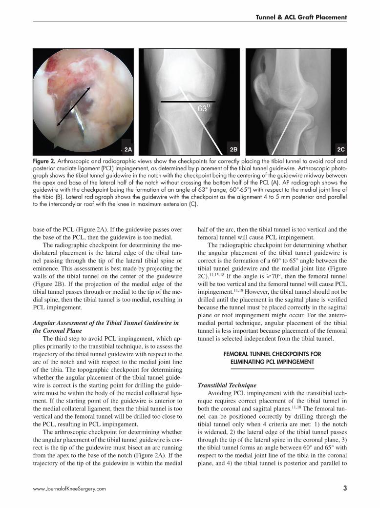
figure �. Arthroscopic and radiographic views show the checkpoints for correctly placing the tibial tunnel to avoid roof and posterior cruciate ligament (PCL) impingement, as determined by placement of the tibial tunnel guidewire. Arthroscopic photo-graph shows the tibial tunnel guidewire in the notch with the checkpoint being the centering of the guidewire midway between the apex and base of the lateral half of the notch without crossing the bottom half of the PCL (A). AP radiograph shows the guidewire with the checkpoint being the formation of an angle of 63° (range, 60°-65°) with respect to the medial joint line of the tibia (B). Lateral radiograph shows the guidewire with the checkpoint as the alignment 4 to 5 mm posterior and parallel to the intercondylar roof with the knee in maximum extension (C).
2C2A 2B
�
THE JOURNAL OF KNEE SURGERY
April 2009 / Vol 22 No 2
the intercondylar roof in the extended knee in the sagittal plane. The advantage of the transtibial technique is that when these 4 criteria for placing the tibial tunnel are met, the placement of the femoral tunnel is automatically cor-rect. The disadvantage is that when any of these 4 criteria is not fulfilled, the femoral tunnel cannot be placed cor-rectly with use of the transtibial technique, and an attempt to salvage the situation is warranted with use of the trans-portal technique.
The following steps outline placement of the femoral tunnel guidewire using the transtibial technique. Based on the diameter of the tunnel, a size-specific femoral aimer is
selected that has an offset designed to give a 1-mm back-wall. The femoral aimer then is inserted through the tibial tunnel, and the tip of the guide is hooked into the over-the-top position. Next, the knee is flexed until the femoral aimer locks in place, which is typically between 50° and 80° of flexion. The femoral aimer then is rotated until the trajectory of the guidewire bisects the arc running from the apex to the base of the notch (Figures 3A-C). Similar to the tibial tunnel guidewire, if the trajectory of the tip of the femoral tunnel guidewire is within the medial half of the arc, then the femoral tunnel will be too vertical and too close to the PCL, resulting in PCL impingement.
3A
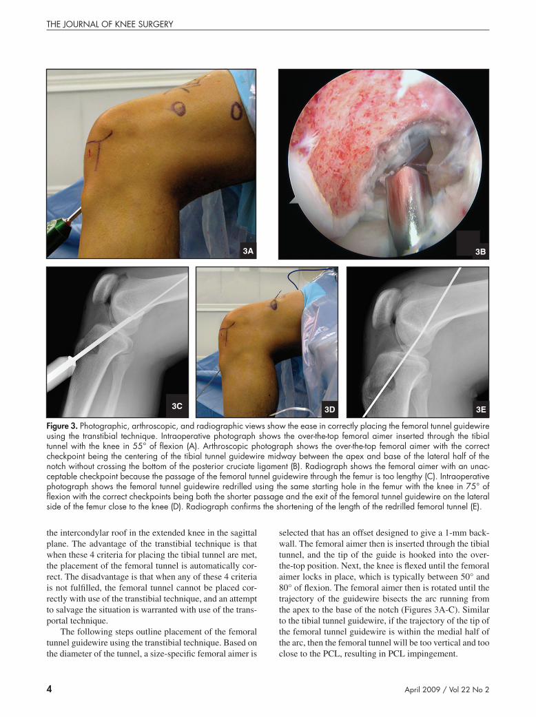
figure �. Photographic, arthroscopic, and radiographic views show the ease in correctly placing the femoral tunnel guidewire using the transtibial technique. Intraoperative photograph shows the over-the-top femoral aimer inserted through the tibial tunnel with the knee in 55° of flexion (A). Arthroscopic photograph shows the over-the-top femoral aimer with the correct checkpoint being the centering of the tibial tunnel guidewire midway between the apex and base of the lateral half of the notch without crossing the bottom of the posterior cruciate ligament (B). Radiograph shows the femoral aimer with an unac-ceptable checkpoint because the passage of the femoral tunnel guidewire through the femur is too lengthy (C). Intraoperative photograph shows the femoral tunnel guidewire redrilled using the same starting hole in the femur with the knee in 75° of flexion with the correct checkpoints being both the shorter passage and the exit of the femoral tunnel guidewire on the lateral side of the femur close to the knee (D). Radiograph confirms the shortening of the length of the redrilled femoral tunnel (E).
3E3C 3D
3B

�
Tunnel & ACL Graft Placement
www.JournalofKneeSurgery.com
Next, a 5-mm deep pilot hole is drilled in the femur, and the femoral aimer and guidewire are removed. The length of the femoral aimer is shortened by drilling the femoral tunnel guidewire with the knee in 80° to 90° of flexion after the guidewire is reinserted up the tibial tun-nel and into the pilot hole (Figures 3D-E). With the knee flexed, the femoral guidewire is drilled through the skin.
The topographic checkpoint for determining whether the coronal placement of the femoral tunnel guidewire is correct is the guidewire should exit the thigh anterolater-ally (Figure 3D). If the guidewire exits the thigh anteri-orly, then the femoral tunnel will be too vertical and too close to the PCL, causing PCL impingement.
The radiographic checkpoint for determining whether the sagittal placement of the femoral tunnel guidewire is correct is best made by projecting the walls of the femoral tunnel on the center of the guidewire (Figure 3E). If the projection of the posterior edge of the femoral tunnel has .1-mm thick backwall, then the femoral tunnel is too an-terior and the tension pattern in the graft will increase in flexion and not match that of the intact ACL.
Transportal TechniqueAvoiding PCL impingement with the transportal tech-
nique requires correct mediolateral placement of the tibial tunnel and correct placement of the femoral tunnel in both the coronal and sagittal planes. Because the placement of the femoral tunnel is independent from the tibial tunnel with the transportal technique, the 3 criteria for placing the tibial tunnel that must be met are: 1) widening of the notch, 2) the lateral edge of the tibial tunnel must pass
through the tip of the lateral spine in the coronal plane, and 3) the tibial tunnel is posterior and parallel to the intercon-dylar roof in the extended knee in the sagittal plane.
The transportal technique has no advantages over the transtibial technique. Although the transportal technique has 1 less criterion for correctly placing the tibial tunnel, the additional criterion for the transtibial technique is a simple task of forming an angle of 60° to 65° between the tibial tunnel guidewire and the medial joint line. In contrast, a blowout of the posterior wall of the femoral tunnel is more difficult to avoid with the transportal tech-nique (Figure 4). The key to avoiding a blowout of the posterior wall of the femoral tunnel is to hyperflex the knee to 120° to 130°. However, this degree of flexion is difficult, and in some cases impossible, to achieve when the leg is clamped in a leg holder and when the thigh is thick or obese. Therefore, the advantage of the transtibial technique is that high flexion of the knee is not required to avoid a blowout, which means the technique works when the leg is in a holder and when the patient has a thick thigh or an obese leg (Figures 3 and 4).
tunnel Placement In sagIttal Plane and roof ImPIngement
Correct placement of the tibial tunnel in the sagittal plane prevents roof impingement and the complications caused by roof impingement, which are loss of extension and instability.1,3-10,12-14,19 Roof impingement occurs when the tibial tunnel is too anterior and the ACL graft contacts the intercondylar roof before the knee reaches terminal
figure �. Photographic, arthroscopic, and radiographic views show the difficulty in correctly placing the femoral tunnel guidewire using the anteromedial portal. Intraoperative photograph shows the over-the-top femoral aimer inserted through the anteromedial portal almost parallel to the longitudinal axis of the femur with the knee in 90° of flexion (A). Arthroscopic pho-tograph shows the over-the-top femoral aimer with the checkpoint being the centering of the tibial tunnel guidewire midway between the apex and base of the lateral half of the notch (black line) without crossing the bottom of the posterior cruciate ligament (B). Radiograph shows the femoral aimer with an unacceptable checkpoint being the too posterior placement of the femoral tunnel guidewire, which would have blown-out the posterior wall (C). Although more knee flexion would have moved the femoral tunnel more anterior, legs clamped in a leg holder and knees in obese legs cannot be flexed beyond 100°, which leads to poor placement of the femoral tunnel.
4C4A 4B
�
THE JOURNAL OF KNEE SURGERY
April 2009 / Vol 22 No 2
extension. Impingement between the ACL graft and in-tercondylar roof creates havoc in the knee, with patients not regaining full extension or regaining full extension af-ter a protracted recovery from rupturing of the ACL graft caused by repeated abrasion or elongation of the graft from stretching around the roof at the outlet of the notch.
A review of the sagittal anatomy of the normal knee and ACL graft cross-sectional dimensions provides crite-ria for tibial tunnel placement to avoid roof impingement.9 The normal ACL lies against the intercondylar roof in the extended knee, which for an anatomic ACL reconstruc-tion requires that the anterior surface of the ACL graft
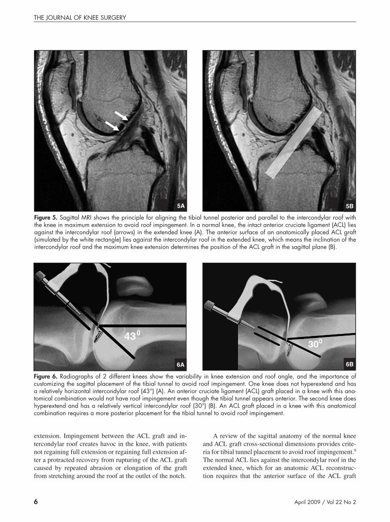
figure �. Sagittal MRI shows the principle for aligning the tibial tunnel posterior and parallel to the intercondylar roof with the knee in maximum extension to avoid roof impingement. In a normal knee, the intact anterior cruciate ligament (ACL) lies against the intercondylar roof (arrows) in the extended knee (A). The anterior surface of an anatomically placed ACL graft (simulated by the white rectangle) lies against the intercondylar roof in the extended knee, which means the inclination of the intercondylar roof and the maximum knee extension determines the position of the ACL graft in the sagittal plane (B).
5A 5B
figure �. Radiographs of 2 different knees show the variability in knee extension and roof angle, and the importance of customizing the sagittal placement of the tibial tunnel to avoid roof impingement. One knee does not hyperextend and has a relatively horizontal intercondylar roof (43°) (A). An anterior cruciate ligament (ACL) graft placed in a knee with this ana-tomical combination would not have roof impingement even though the tibial tunnel appears anterior. The second knee does hyperextend and has a relatively vertical intercondylar roof (30°) (B). An ACL graft placed in a knee with this anatomical combination requires a more posterior placement for the tibial tunnel to avoid roof impingement.
6A 6B
�
Tunnel & ACL Graft Placement
www.JournalofKneeSurgery.com
also lie against the intercondylar roof with the knee in maximum extension (Figure 5). There is wide variability in roof angle and knee extension among patients, which means placement of the tibial tunnel should be custom-ized based on an individual patient’s anatomy (Figures 6 and 7).6-8,10,13,19 The maintenance of this relationship means that the tibial tunnel guidewire should run parallel to the intercondylar roof when the knee is in maximum extension (Figures 2C and 6).
The cross-sectional dimension and orientation of the ACL graft (ie, round soft-tissue graft or rectangular bone plug graft) determines the distance between the center of the tibial tunnel and the intercondylar roof. For a 9-mm diameter soft-tissue graft, which has a round cross-sec-tional area, the distance between the intercondylar roof and the center of the guidewire should be 5 mm. For a 10-mm wide and 4-mm thick bone-patellar tendon-bone graft, which has a rectangular cross-sectional area, the distance between the intercondylar roof and the anterior surface of the guidewire depends on the direction the cor-tical surface of the bone plug faces within the tibial tun-nel. If the cortical surface of the bone plugs faces medial, lateral, or anterior, then the distance between the inter-condylar roof and guidewire should be 5 mm. However, if the cortical surface of the bone plug faces posterior and an interference screw is placed anterior to the bone plug, then the distance between the intercondylar roof and the guidewire should be 0 mm [Query #1: Please verify 0 mm is correct].
tIbIal tunnel cHeckPoInts for elImInatIng roof ImPIngement
Arthroscopic and radiographic checkpoints that are useful for detecting roof impingement before drilling the tibial tunnel do so by assessing the space between the tib-
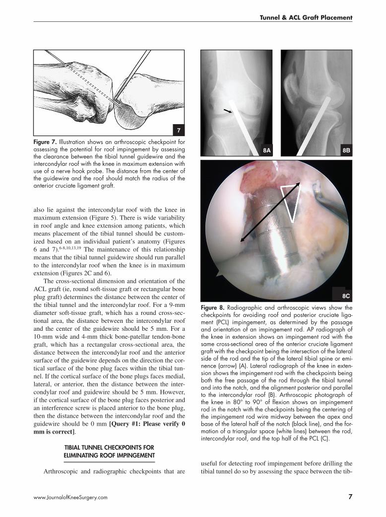
figure �. Illustration shows an arthroscopic checkpoint for assessing the potential for roof impingement by assessing the clearance between the tibial tunnel guidewire and the intercondylar roof with the knee in maximum extension with use of a nerve hook probe. The distance from the center of the guidewire and the roof should match the radius of the anterior cruciate ligament graft.
7
8A 8B
figure 8. Radiographic and arthroscopic views show the checkpoints for avoiding roof and posterior cruciate liga-ment (PCL) impingement, as determined by the passage and orientation of an impingement rod. AP radiograph of the knee in extension shows an impingement rod with the same cross-sectional area of the anterior cruciate ligament graft with the checkpoint being the intersection of the lateral side of the rod and the tip of the lateral tibial spine or emi-nence (arrow) (A). Lateral radiograph of the knee in exten-sion shows the impingement rod with the checkpoints being both the free passage of the rod through the tibial tunnel and into the notch, and the alignment posterior and parallel to the intercondylar roof (B). Arthroscopic photograph of the knee in 80° to 90° of flexion shows an impingement rod in the notch with the checkpoints being the centering of the impingement rod wire midway between the apex and base of the lateral half of the notch (black line), and the for-mation of a triangular space (white lines) between the rod, intercondylar roof, and the top half of the PCL (C).
8C
8
THE JOURNAL OF KNEE SURGERY
April 2009 / Vol 22 No 2
ial tunnel guidewire and intercondylar roof with the knee in maximum hyperextension. One arthroscopic check-point is to measure the space between the anterior surface of the guidewire and the intercondylar roof with the knee in maximum extension. The space can be measured by positioning a 2-mm thick nerve hook probe between the guidewire and intercondylar roof with the knee in exten-sion (Figure 7). The clearance between the center of the guidewire and the intercondylar roof should match the ra-dius of the ACL graft.
After satisfactory position of the tibial tunnel guide-wire is verified arthroscopically, a radiographic check-point is used to determine whether roof impingement is avoided. The tibial tunnel guidewire is advanced 2.5 cm into the intercondylar notch. A lateral radiograph is ob-tained with the knee in maximum hyperextension, and the space between the center of the tibial tunnel guide wire and the intercondylar roof is measured (Figure 2C). If the space matches the clearances calculated based on the cross-sectional dimensions and orientation of the ACL graft, then the tibial tunnel guidewire is properly placed in the sagittal plane. However, the tibial tunnel should not be drilled until placement in the coronal plane is verified because the tunnel also must be placed correctly in the coronal plane for both the transtibial and transportal tech-nique or PCL impingement might occur.
cHeckPoInts for assessIng ImPIngement after drIllIng tHe tIbIal tunnel
There are several checkpoints for verifying the avoid-
ance of PCL and roof impingement after drilling the tibial tunnel but before drilling the femoral tunnel and inserting the ACL graft. An arthroscopic checkpoint for determin-ing whether the tibial tunnel is placed without PCL im-pingement is to simulate the trajectory of the ACL graft by inserting an impingement rod or drill bit though the tibial tunnel and into the notch and verifying there is a triangular space between the rod and PCL (Figure 8). An-other arthroscopic checkpoint is to verify the center of the femoral tunnel is aligned midway between the apex and base of the notch (Figure 8).
A radiographic checkpoint for determining whether the tibial tunnel is placed without PCL impingement is to verify that the impingement rod passes through the tip of the lateral spine and that the angle with respect to the medial joint line is between 60° and 65° (Figure 8). If the tibial tunnel is too medial or too vertical, then the femoral tunnel should not be drilled through the tibial tunnel but should be placed with use of the transportal technique.
A topographic checkpoint for determining whether the tibial tunnel is placed without roof impingement is to insert an impingement rod or drill bit into the notch through the tibial tunnel with the knee in maximum exten-sion [Query #2: Please verify the addition of “exten-sion” is correct.] and verify the rod freely passes into the notch. The radiographic checkpoint verifies that the drill bit or impingement rod passes into the notch through the tibial tunnel with the knee in maximum extension (Fig-ure 8B). If the drill bit or impingement rod does not pass freely, then a roofplasty is performed until there is suffi-cient clearance. Because a roofplasty adversely affects the
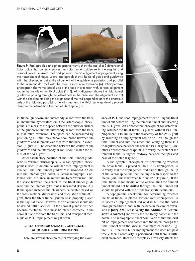
figure 9. Radiographic and photographic views show the use of a 3-dimensional tibial guide that correctly places the tibial tunnel guidewire in the sagittal and coronal planes to avoid roof and posterior cruciate ligament impingement using the transtibial technique. Lateral radiograph shows the tibial guide and guidewire with the checkpoint being the alignment of the guidewire posterior and parallel to the intercondylar roof with the knee in maximum extension (A). Intraoperative photograph shows the lateral side of the knee in extension with coronal alignment rod in the handle of the tibial guide (*) (B). AP radiograph shows the tibial tunnel guidewire passing through the lateral hole in the bullet and the alignment rod (*) with the checkpoints being the alignment of the rod perpendicular to the anatomic axis of the tibia and parallel to the joint line, and the tibial tunnel guidewire placed closer to the lateral than the medial tibial spine (C).
9C
9A 9B
9
Tunnel & ACL Graft Placement
www.JournalofKneeSurgery.com
anterior laxity and tension pattern in the graft,5 the best method for preventing roof impingement is to correctly place the tibial tunnel in the sagittal plane and not perform a roofplasty.
tIbIal drIll guIde
The placement of the tibial tunnel is a complicated, 3-dimensional exercise with a point and shoot guide be-cause the criterion for correct placement must be achieved simultaneously in both the sagittal and coronal planes. To simply solve this 3-D problem without the use of the ra-diographic checkpoints, we use a 3-D tibial guide (65° Howell Guide; Biomet Sports Medicine Inc, Warsaw, Ind) (Figure 9). The tip of the tibial guide is 9.5-mm wide, which matches the width of a typical soft-tissue graft (ie, 8 to 9 mm). The tip of the guide is used to assess the width of the notch, verify the adequacy of the wallplasty, and set the coronal and sagittal position of the tibial tunnel. The lateral femoral condyle and PCL keep the tip of the guide from moving medial or lateral, and the intercondylar roof and the tibial plateau keeps the tip from moving anterior and posterior. An alignment rod inserted in the handle of the guide sets the angular rotation of the tibial guide in the coronal plane by aligning the rod perpendicular to the tibia and parallel to the joint line (Figure 9C). The guidewire is drilled with the knee in maximum hyperextension, which customizes the placement for the tibial tunnel guidewire in the sagittal plane and anatomically places the tibial tun-nel without roof impingement or the need for a roofplasty (Figures 9A-B). This tibial guide consistently and quickly places the tibial tunnel without the need for radiographic confirmation or the imprecision of using the footprint of the ACL insertion.1,12
fInal assessment of graft and tunnel Placement
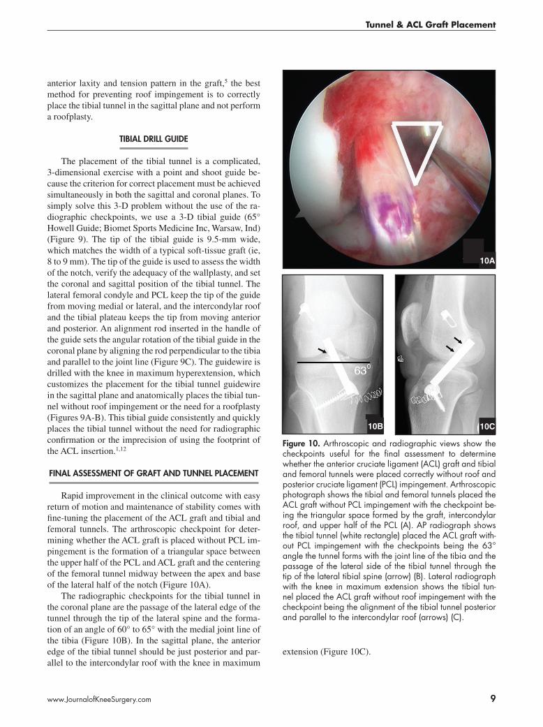
Rapid improvement in the clinical outcome with easy return of motion and maintenance of stability comes with fine-tuning the placement of the ACL graft and tibial and femoral tunnels. The arthroscopic checkpoint for deter-mining whether the ACL graft is placed without PCL im-pingement is the formation of a triangular space between the upper half of the PCL and ACL graft and the centering of the femoral tunnel midway between the apex and base of the lateral half of the notch (Figure 10A).
The radiographic checkpoints for the tibial tunnel in the coronal plane are the passage of the lateral edge of the tunnel through the tip of the lateral spine and the forma-tion of an angle of 60° to 65° with the medial joint line of the tibia (Figure 10B). In the sagittal plane, the anterior edge of the tibial tunnel should be just posterior and par-allel to the intercondylar roof with the knee in maximum
extension (Figure 10C).
10C
figure �0. Arthroscopic and radiographic views show the checkpoints useful for the final assessment to determine whether the anterior cruciate ligament (ACL) graft and tibial and femoral tunnels were placed correctly without roof and posterior cruciate ligament (PCL) impingement. Arthroscopic photograph shows the tibial and femoral tunnels placed the ACL graft without PCL impingement with the checkpoint be-ing the triangular space formed by the graft, intercondylar roof, and upper half of the PCL (A). AP radiograph shows the tibial tunnel (white rectangle) placed the ACL graft with-out PCL impingement with the checkpoints being the 63° angle the tunnel forms with the joint line of the tibia and the passage of the lateral side of the tibial tunnel through the tip of the lateral tibial spine (arrow) (B). Lateral radiograph with the knee in maximum extension shows the tibial tun-nel placed the ACL graft without roof impingement with the checkpoint being the alignment of the tibial tunnel posterior and parallel to the intercondylar roof (arrows) (C).
10A
10B
�0
THE JOURNAL OF KNEE SURGERY
April 2009 / Vol 22 No 2
references
1. Cuomo P, Edwards A, Giron F, Bull AM, Amis AA, Agliet-ti P. Validation of the 65° Howell guide for anterior cruci-ate ligament reconstruction. Arthroscopy. 2006;22:70-75.
2. Fujimoto E, Sumen Y, Deie M, Yasumoto M, Kobayashi K, Ochi M. Anterior cruciate ligament graft impingement against the posterior cruciate ligament: Diagnosis using MRI plus three-dimensional reconstruction software. Magn Reson Imaging. 2004;22:1125-1129.
3. Goss BC, Howell SM, Hull ML. Quadriceps load ag-gravates and roofplasty mitigates active impingement of anterior cruciate ligament grafts against the intercondylar roof. J Orthop Res. 1998;16:611-617.
4. Goss BC, Hull ML, Howell SM. Contact pressure and tension in anterior cruciate ligament grafts subjected to roof impingement during passive extension. J Orthop Res. 1997;15:263-268.
5. Hame SL, Markolf KL, Hunter DM, Oakes DA, Zoric B. Effects of notchplasty and femoral tunnel position on excursion patterns of an anterior cruciate ligament graft. Arthroscopy. 2003;19:340-345.
6. Howell SM. Arthroscopic roofplasty: A method for cor-recting an extension deficit caused by roof impinge-ment of an anterior cruciate ligament graft. Arthroscopy. 1992;8:375-379.
7. Howell SM, Barad SJ. Knee extension and its relationship to the slope of the intercondylar roof: Implications for positioning the tibial tunnel in anterior cruciate ligament reconstructions. Am J Sports Med. 1995;23:288-294.
8. Howell SM, Clark JA. Tibial tunnel placement in anterior cruciate ligament reconstructions and graft impingement. Clin Orthop. 1992;(283):187-195.
9. Howell SM, Clark JA, Farley TE. A rationale for predict-ing anterior cruciate graft impingement by the intercon-dylar roof: A magnetic resonance imaging study. Am J Sports Med. 1991;19:276-282.
10. Howell SM, Clark JA, Farley TE. Serial magnetic reso-nance study assessing the effects of impingement on the MR image of the patellar tendon graft. Arthroscopy.
1992;8:350-358. 11. Howell SM, Gittins ME, Gottlieb JE, Traina SM, Zoellner
TM. The relationship between the angle of the tibial tun-nel in the coronal plane and loss of flexion and anterior laxity after anterior cruciate ligament reconstruction. Am J Sports Med. 2001;29:567-574.
12. Howell SM, Lawhorn KW. Gravity reduces the tibia when using a tibial guide that targets the intercondylar roof. Am J Sports Med. 2004;32:1702-1710.
13. Howell SM, Taylor MA. Failure of reconstruction of the anterior cruciate ligament due to impingement by the in-tercondylar roof. J Bone Joint Surg Am. 1993;75:1044-1055.
14. Muneta T, Yamamoto H, Ishibashi T, Asahina S, Mu-rakami S, Furuya K. The effects of tibial tunnel placement and roofplasty on reconstructed anterior cruciate ligament knees. Arthroscopy. 1995;11:57-62.
15. Pena E, Calvo B, Martinez MA, Palanca D, Doblare M. Influence of the tunnel angle in ACL reconstructions on the biomechanics of the knee joint. Clin Biomech (Bristol, Avon). 2006;21:508-516.
16. Rue JP, Ghodadra N, Bach BR Jr. Femoral tunnel place-ment in single-bundle anterior cruciate ligament recon-struction: A cadaveric study relating transtibial lateralized femoral tunnel position to the anteromedial and postero-lateral bundle femoral origins of the anterior cruciate liga-ment. Am J Sports Med. 2008;36:73-79.
17. Rue JP, Ghodadra N, Lewis PB, Bach BR Jr. Femoral and tibial tunnel position using a transtibial drilled anterior cruciate ligament reconstruction technique. J Knee Surg. 2008;21:246-249.
18. Simmons R, Howell SM, Hull ML. Effect of the angle of the femoral and tibial tunnels in the coronal plane and incremental excision of the posterior cruciate ligament on tension of an anterior cruciate ligament graft: An in vitro study. J Bone Joint Surg Am. 2003;85:1018-1029.
19. Watanabe BM, Howell SM. Arthroscopic findings associ-ated with roof impingement of an anterior cruciate liga-ment graft. Am J Sports Med. 1995;23:616-625.