Embed Size (px)
Citation preview
Checkpointing Apparatus and Algorithms forFault-Tolerant Tightly-Coupled Multiprocessors
Dwight Sunada
Technical Report: CSL-TR-99-785
July 1999
The initial phase of this research was supported by a financial grant fromHewlett-Packard Company.
ii
Checkpointing Apparatus and Algorithms for Fault-TolerantTightly-Coupled Multiprocessors
Dwight Sunada
Technical Report: CSL-TR-99-785
July 1999
Computer Systems LaboratoryDepartments of Electrical Engineering and Computer Science
Stanford UniversityWilliam Gates Building, 4A-408Stanford, California 94305-9040
<e-mail: [email protected]>
Abstract
The apparatus and algorithms for establishing checkpoints on a tightly-coupled multiprocessor
(TCMP) fall naturally into three broad classes: tightly synchronized method, loosely synchronized
method, and unsynchronized method. The algorithms in the class of the tightly synchronized
method force the immediate establishment of a checkpoint whenever a dependency between two
processors arises. The algorithms in the class of the loosely synchronized method record this
dependency and, hence, do not require the immediate establishment of a checkpoint if a
dependency does arise; when a processor chooses to establish a checkpoint, the processor will
query the dependency records to determine other processors that must also establish a
checkpoint. The algorithms in the class of the unsynchronized method allow a processor to
establish a checkpoint without regard to any other processor. Within this framework, we develop
four apparatus and algorithms: distributed recoverable shared memory (DRSM), DRSM for
communication checkpoints (DRSM-C), DRSM with half of the memory (DRSM-H), and DRSM
with logs (DRSM-L). DRSM-C is an algorithm in the class of the tightly synchronized method,
and DRSM and DRSM-H are algorithms in the class of the loosely synchronized method. DRSM-
L is an algorithm in the class of the unsynchronized method and is the first of its kind for a TCMP.
DRSM-L has the best performance in terms of minimizing the impact of establishing checkpoints
(or logs) on the running applications and has the least expensive hardware.
Key Words and Phrases: audit trail, checkpoint, fault tolerance, roll-back recovery,
tightly-coupled multiprocessor
iii
© Copyright by Dwight Sunada 1999
All Rights Reserved

iv
I certify that I have read this dissertation and that in my opinion it is fully
adequate, in scope and quality, as a dissertation for the degree of Doctor of
Philosophy.
.
Michael J. Flynn
I certify that I have read this dissertation and that in my opinion it is fully
adequate, in scope and quality, as a dissertation for the degree of Doctor of
Philosophy.
.
David B. Glasco
I certify that I have read this dissertation and that in my opinion it is fully
adequate, in scope and quality, as a dissertation for the degree of Doctor of
Philosophy.
.
Bernard Widrow
Approved for the University Committee on Graduate Studies:
.
v
Acknowledgments
Starting from the 7th grade of intermediate school, I have hoped to obtain a Doctor-of-Philosophy
degree in either (1) computer science or (2) a field related to computer science. More than 20
years later, I shall earn a Doctor of Philosophy (Ph. D.) in electrical engineering; my Ph. D.
research is focused on the architecture of computer systems. Although I encountered many
obstacles along the way to earning a Ph. D., I have finally fulfilled one of my childhood dreams.
Several people contributed to my accomplishment. At Stanford University, I thank both Professor
Michael J. Flynn and Professor David B. Glasco for serving as my advisors. I thank Professor
Bernard Widrow for being the 3rd member of my reading committee. I thank Professor John M.
Cioffi for serving as the chairman of my orals committee and Professor Abbas El-Gamal for being
the 4th member of my orals committee. In addition, I thank the colleagues in my research group
and the students in the ÒEE 385BÓ seminar for listening to my numerous practice presentations
(for the Ph. D. oral defense) and for offering helpful suggestions.
At the University of Houston (in Texas), I thank Professor Pauline Markenscoff for believing that I
can do research. The University of Houston (UH) has a tiny fraction of the resources and the
intellectual environment that Stanford University has. Research positions in computer
architecture at UH were rare Ð if they even existed. Nonetheless, after I graduated with a
Bachelor-of-Science degree in electrical engineering from UH in 1988 May, I looked for a summer
job doing research in computer architecture. By sheer coincidence, Professor Markenscoff had
an opening for such a job and hired me to do research on the subject of multiprocessors. In this
research, I used computer simulation to develop algorithms for assigning subtasks (of a whole
task) to the processors in a multiprocessor. This work and a strong letter of recommendation
from Professor Markenscoff significantly helped me to successfully obtain a 3-year graduate
fellowship (for graduate study at Stanford University) from the National Science Foundation in
1989. Also, this research culminated in my first significant paper: ÒComputation of Tasks
Modeled By Directed Acyclic Graphs on Distributed Computer Systems: Allocation without
Subtask Replication" on pages 2400 - 2404 in volume 3 of the 1990 IEEE International
Symposium on Circuits and Systems. I am very grateful to Professor Markenscoff.
vi
To complete my academic acknowledgments, I thank 3 teachers from secondary school for
having taught me well. They are Ms. Dillion from my American-history class in the 10th grade (at
Klein High School in Klein, Texas), Ms. Little from my science class in the 7th grade (at Strack
Intermediate School in Klein, Texas), and Ms. Lacy in the 3rd grade (at Hidden Valley Elementary
School in Houston, Texas). All 3 teachers asked me to remember them if I ever became famous.
Since obtaining the Ph. D. is a type of fame, I now honor their request. I thank all 3 teachers for
having taught me well.
In my personal life, I thank my grandfather, Chew Doo Wong, for his kindness towards me. I
have suffered very many, painful experiences in my life; during almost all of these painful
experiences, no person genuinely cared about me. In particular, I suffered one of these painful
experiences when I was approximately 13 years old. At that time, my grandfather was in a
position to help me, and he conscientiously helped me in a substantial way. Shortly thereafter, he
passed away Ð into the kind and gentle place. Although more than 20 years have elapsed since
his death, I still occasionally remember him and his kindness. I thank my grandfather very much
for his kindness on that occasion long ago.
Finally, I dedicate this dissertation (and any benefit derived from it) to the hope that both (1) the
adult survivors of child abuse and (2) abused children will someday find inner peace and joy. As
for the victims who did not survive child abuse, I dedicate this dissertation (and any benefit
derived from it) to the hope that they will find inner peace and joy in the kind and gentle place
beyond this cruel world.
vii
Table of Contents
Chapter 1. Introduction ......................................................................................................................... 1
1.1. Tightly-Coupled Multiprocessor (TCMP).................................................................................. 1
1.2. Fault-tolerant TCMP.................................................................................................................. 2
1.3. Research on Roll-back Recovery............................................................................................. 3
Chapter 2. Background......................................................................................................................... 5
2.1. Dependencies ........................................................................................................................... 5
2.2. Classes of Algorithms ............................................................................................................. 10
Chapter 3. Assumptions ..................................................................................................................... 12
3.1. Fault-tolerant Components..................................................................................................... 12
3.2. Distinction between Processor and Directory Controller....................................................... 13
Chapter 4. Distributed Recoverable Shared Memory (DRSM)......................................................... 15
4.1. Introduction.............................................................................................................................. 15
4.2. Prior Work ............................................................................................................................... 15
4.3. Background: Recoverable Shared Memory (RSM)............................................................... 15
4.3.1. Dependency Matrix ......................................................................................................... 16
4.3.2. Last-Writer Indicator ........................................................................................................ 16
4.3.3. Checkpoint Counters....................................................................................................... 17
4.3.4. Memory for Tentative Checkpoint................................................................................... 17
4.3.5. Memory for Permanent Checkpoint................................................................................ 17
4.3.6. Establishing Checkpoints ................................................................................................ 17
4.3.7. New Requests after Initiating Checkpoint ...................................................................... 19
4.4. Apparatus of DRSM................................................................................................................ 19
4.5. Triggers of Checkpoint Establishment ................................................................................... 22
4.6. Establishing Tentative Checkpoints ....................................................................................... 22
4.6.1. General Overview............................................................................................................ 22
4.6.2. Details .............................................................................................................................. 24
4.6.3. Dependent Processors and Dependent DRSM Modules .............................................. 25
4.7. Establishing Permanent Checkpoints .................................................................................... 26
4.7.1. General Overview............................................................................................................ 26
4.7.2. Details .............................................................................................................................. 26
4.8. Additional Features................................................................................................................. 27

viii
4.8.1. Artificially Dependent Processors................................................................................... 27
4.8.2. Arbiter............................................................................................................................... 28
4.9. Recovery from a Fault ............................................................................................................ 28
Chapter 5. Distributed Recoverable Shared Memory for Communication Checkpoints (DRSM-C)
.............................................................................................................................................................. 31
5.1. Introduction.............................................................................................................................. 31
5.2. Prior Work ............................................................................................................................... 31
5.3. Apparatus ................................................................................................................................ 32
5.4. Triggers of Checkpoint Establishment ................................................................................... 33
5.5. Establishing Checkpoints ....................................................................................................... 33
5.5.1. General Overview............................................................................................................ 33
5.5.2. Details .............................................................................................................................. 34
5.6. Recovery from a Fault ............................................................................................................ 35
Chapter 6. Distributed Recoverable Shared Memory with Half of the Memory (DRSM-H)............. 37
6.1. Introduction.............................................................................................................................. 37
6.2. Apparatus ................................................................................................................................ 37
6.3. Memory Cache........................................................................................................................ 39
6.4. Triggers of Checkpoint Establishment ................................................................................... 40
6.5. Establishing Tentative Checkpoints ....................................................................................... 40
6.6. Establishing Permanent Checkpoints .................................................................................... 41
6.6.1. General Overview............................................................................................................ 41
6.6.2. Details .............................................................................................................................. 42
6.7. Recovery from a Fault ............................................................................................................ 43
Chapter 7. Distributed Recoverable Shared Memory with Logs (DRSM-L)..................................... 44
7.1. Introduction.............................................................................................................................. 44
7.2. Apparatus ................................................................................................................................ 44
7.3. Audit Trail ................................................................................................................................ 46
7.4. Optimizations .......................................................................................................................... 48
7.5. Triggers of Checkpoint Establishment ................................................................................... 49
7.5.1. List of Triggers................................................................................................................. 49
7.5.2. Context Switch................................................................................................................. 49
7.6. Establishing Checkpoints ....................................................................................................... 50
7.7. Recovery from a Fault ............................................................................................................ 51
7.8. Pedagogical Example ............................................................................................................. 54
7.9. Optimal Size of Line Buffer and Counter Buffer .................................................................... 59
7.10. Detailed Description.............................................................................................................. 60
Chapter 8. Simulation Environment and Benchmarks ...................................................................... 61
ix
8.1. Multiprocessor Simulator ........................................................................................................ 61
8.2. Benchmarks ............................................................................................................................ 62
Chapter 9. Results and Analysis........................................................................................................ 64
9.1. Overall Performance of Benchmarks ..................................................................................... 64
9.2. Performance Impact of Establishing Checkpoints................................................................. 71
9.2.1. Checkpoints ..................................................................................................................... 72
9.2.2. Negative Acknowledgments and Upgrade Misses ........................................................ 77
9.3. Checkpoint Data...................................................................................................................... 80
9.4. Audit-Trail Data ....................................................................................................................... 83
9.5. Extent of Checkpoint Dependencies...................................................................................... 85
9.6. Memory Cache and Dirty-Shared Data.................................................................................. 85
9.7. DRSM Versus DRSM-L .......................................................................................................... 87
9.8. Additional Observations.......................................................................................................... 89
9.8.1. Delay for Establishing Checkpoints ................................................................................ 89
9.8.2. Number of Negative Acknowledgments (NAKs) ............................................................ 90
9.8.3. Number of Upgrade Misses ............................................................................................ 93
9.9. High Rate of Checkpoints for All Processors......................................................................... 93
Chapter 10. Conclusions .................................................................................................................... 94
10.1. DRSM-C ................................................................................................................................ 94
10.2. DRSM and DRSM-H............................................................................................................. 94
10.3. DRSM-L................................................................................................................................. 94
10.4. Future Work .......................................................................................................................... 95
10.4.1. Simulation ...................................................................................................................... 95
10.4.2. Proof of Concept............................................................................................................ 96
Appendix A. Precise Description of DRSM-L .................................................................................... 97
Appendix B. Results for Timer Expiration per 2,000,000 Cycles.................................................... 112
B.1. Overall Performance of Benchmarks................................................................................... 112
B.2. Performance Impact of Establishing Checkpoints .............................................................. 118
B.2.1. Checkpoints................................................................................................................... 118
B.2.2. Negative Acknowledgments and Upgrade Misses...................................................... 121
B.3. Checkpoint Data ................................................................................................................... 123
B.4. Audit-Trail Data..................................................................................................................... 126
B.5. Extent of Checkpoint Dependencies ................................................................................... 126
B.6. Memory Cache and Dirty-Shared Data ............................................................................... 127
B.7. Additional Observations ....................................................................................................... 129
List of References.............................................................................................................................. 132
x
List of Tables
Table 1. Checkpoints for DRSM......................................................................................................... 73
Table 2. Checkpoints for DRSM-C..................................................................................................... 74
Table 3. Checkpoints for DRSM-H..................................................................................................... 75
Table 4. Checkpoints for DRSM-L ..................................................................................................... 76
Table 5. Negative Acknowledgments and Upgrade Misses for DRSM............................................ 78
Table 6. Negative Acknowledgments and Upgrade Misses for DRSM-C........................................ 78
Table 7. Negative Acknowledgments and Upgrade Misses for DRSM-H........................................ 79
Table 8. Negative Acknowledgments and Upgrade Misses for DRSM-L......................................... 79
Table 9. Data Saved per Processor per Checkpoint for DRSM ....................................................... 80
Table 10. Data Saved per Processor for DRSM ............................................................................... 80
Table 11. Data Saved per Processor per Checkpoint for DRSM-C ................................................. 81
Table 12. Data Saved per Processor for DRSM-C ........................................................................... 82
Table 13. Data Saved per Processor per Checkpoint for DRSM-H ................................................. 82
Table 14. Data Saved per Processor for DRSM-H ........................................................................... 83
Table 15. Audit-Trail Data (entries in line buffer; entries in counter buffer; ratio)............................ 84
Table 16. Extent of Checkpoint Dependencies for DRSM................................................................ 85
Table 17. Extent of Checkpoint Dependencies for DRSM-H............................................................ 85
Table 18. Statistics about Dirty-Shared Data .................................................................................... 87
Table 19. Timer-triggered Checkpoints: (number for processor #3; average for other processors)
.............................................................................................................................................................. 89
Table 20. Checkpoints for DRSM .................................................................................................... 118
Table 21. Checkpoints for DRSM-C................................................................................................. 119
Table 22. Checkpoints for DRSM-H................................................................................................. 120
Table 23. Checkpoints for DRSM-L ................................................................................................. 121
Table 24. Negative Acknowledgments and Upgrade Misses for DRSM........................................ 121
Table 25. Negative Acknowledgments and Upgrade Misses for DRSM-C.................................... 122
Table 26. Negative Acknowledgments and Upgrade Misses for DRSM-H.................................... 122
Table 27. Negative Acknowledgments and Upgrade Misses for DRSM-L .................................... 123
Table 28. Data Saved per Processor per Checkpoint for DRSM ................................................... 123
Table 29. Data Saved per Processor for DRSM ............................................................................. 124
Table 30. Data Saved per Processor per Checkpoint for DRSM-C ............................................... 124
xi
Table 31. Data Saved per Processor for DRSM-C ......................................................................... 125
Table 32. Data Saved per Processor per Checkpoint for DRSM-H ............................................... 125
Table 33. Data Saved per Processor for DRSM-H ......................................................................... 126
Table 34. Audit-Trail Data (entries in line buffer; entries in counter buffer; ratio).......................... 126
Table 35. Extent of Checkpoint Dependencies for DRSM.............................................................. 126
Table 36. Extent of Checkpoint Dependencies for DRSM-H.......................................................... 127
Table 37. Statistics about Dirty-Shared Data ..................................................................................128
xii
List of Illustrations
Figure 1. Basic Architecture of Tightly-Coupled Multiprocessor (TCMP)........................................... 2
Figure 2. Roll-back Dependency for Write-Read Interaction .............................................................. 6
Figure 3. Checkpoint Dependency for Write-Read Interaction........................................................... 7
Figure 4. Roll-back/Checkpoint Dependency for Write-Write Interaction with Writes to Different
Words ..................................................................................................................................................... 8
Figure 5. Roll-back Dependency for Write-Write Interaction with Writes to the Same Word............ 8
Figure 6. Checkpoint Dependency for Write-Write Interaction with Writes to the Same Word......... 9
Figure 7. Dependencies to Classes of Checkpointing Algorithms.................................................... 10
Figure 8. Tightly-Coupled Multiprocessor (TCMP)............................................................................ 13
Figure 9. Recoverable Shared Memory (RSM)................................................................................. 16
Figure 10. Flow of Checkpoint ........................................................................................................... 18
Figure 11. Distributed Recoverable Shared Memory (DRSM) ......................................................... 20
Figure 12. Transition of State for 2-Bit State Register ...................................................................... 21
Figure 13. Flow of Tentative Checkpoint ........................................................................................... 23
Figure 14. Flow of Permanent Checkpoint ........................................................................................ 27
Figure 15. Distributed Recoverable Shared Memory for Communication Checkpoints (DRSM-C)
.............................................................................................................................................................. 32
Figure 16. Flow of Checkpoint ........................................................................................................... 34
Figure 17. Distributed Recoverable Shared Memory with Half of the Memory (DRSM-H) ............. 38
Figure 18. Flow of Permanent Checkpoint ........................................................................................ 41
Figure 19. Distributed Recoverable Shared Memory with Logs (DRSM-L) ..................................... 45
Figure 20. Transition of State of Both Processor and 2nd-Level Cache.......................................... 46
Figure 21. Normal Execution of Processor........................................................................................ 55
Figure 22. Recovery of Processor ..................................................................................................... 56
Figure 23. Completion of Recovery of Processor ............................................................................. 58
Figure 24. Base Multiprocessor ......................................................................................................... 61
Figure 25. Benchmark #1 ................................................................................................................... 65
Figure 26. Benchmark #2 ................................................................................................................... 66
Figure 27. Benchmark #3 ................................................................................................................... 67
Figure 28. Benchmark #4 ................................................................................................................... 68
Figure 29. Benchmark #5 ................................................................................................................... 69
xiii
Figure 30. Benchmark #6 ................................................................................................................... 70
Figure 31. Communication Improved by Checkpoint ........................................................................ 71
Figure 32. Performance of Memory Cache ....................................................................................... 86
Figure 33. Effect of Irregular Checkpointing -- Processor #3 with High Checkpointing Rate ......... 88
Figure 34. Delay for Establishing Checkpoints per Processor ......................................................... 90
Figure 35. Number of Negative Acknowledgments (NAKs) per Processor ..................................... 91
Figure 36. Number of Upgrade Misses per Processor...................................................................... 92
Figure 37. Benchmark #1 ................................................................................................................. 112
Figure 38. Benchmark #2 ................................................................................................................. 113
Figure 39. Benchmark #3 ................................................................................................................. 114
Figure 40. Benchmark #4 ................................................................................................................. 115
Figure 41. Benchmark #5 ................................................................................................................. 116
Figure 42. Benchmark #6 ................................................................................................................. 117
Figure 43. Performance of Memory Cache ..................................................................................... 127
Figure 44. Delay for Establishing Checkpoints per Processor ....................................................... 129
Figure 45. Number of Negative Acknowledgments (NAKs) per Processor ................................... 130
Figure 46. Number of Upgrade Misses per Processor.................................................................... 131
1
Chapter 1. Introduction
1.1. Tightly-Coupled Multiprocessor (TCMP)
The tightly-coupled multiprocessor (TCMP), where specialized hardware maintains the image of a
single shared memory, has the highest performance among the various types of computer
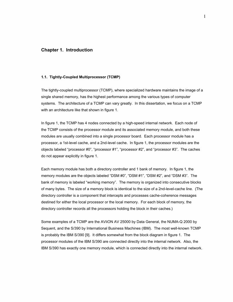
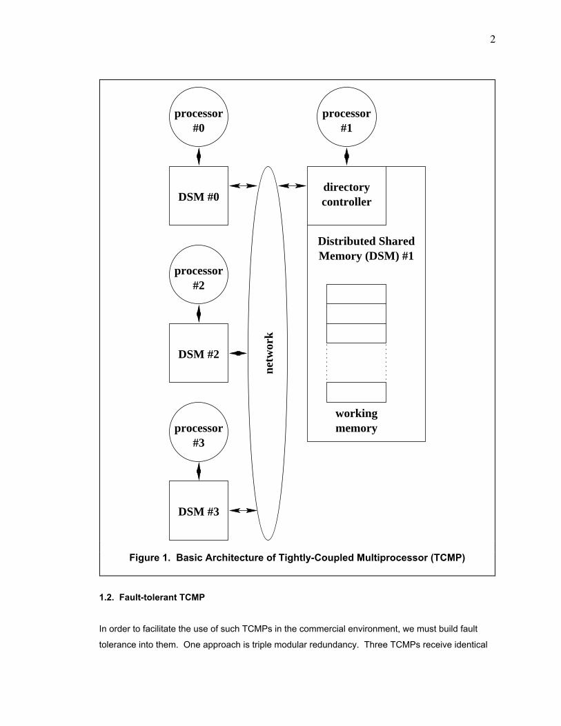
systems. The architecture of a TCMP can vary greatly. In this dissertation, we focus on a TCMP
with an architecture like that shown in figure 1.
In figure 1, the TCMP has 4 nodes connected by a high-speed internal network. Each node of
the TCMP consists of the processor module and its associated memory module, and both these
modules are usually combined into a single processor board. Each processor module has a
processor, a 1st-level cache, and a 2nd-level cache. In figure 1, the processor modules are the
objects labeled Òprocessor #0Ó, Òprocessor #1Ó, Òprocessor #2Ó, and Òprocessor #3Ó. The caches
do not appear explicitly in figure 1.
Each memory module has both a directory controller and 1 bank of memory. In figure 1, the
memory modules are the objects labeled ÒDSM #0Ó, ÒDSM #1Ó, ÒDSM #2Ó, and ÒDSM #3Ó. The
bank of memory is labeled Òworking memoryÓ. The memory is organized into consecutive blocks
of many bytes. The size of a memory block is identical to the size of a 2nd-level-cache line. (The
directory controller is a component that intercepts and processes cache-coherence messages
destined for either the local processor or the local memory. For each block of memory, the
directory controller records all the processors holding the block in their caches.)
Some examples of a TCMP are the AViiON AV 25000 by Data General, the NUMA-Q 2000 by
Sequent, and the S/390 by International Business Machines (IBM). The most well-known TCMP
is probably the IBM S/390 [9]. It differs somewhat from the block diagram in figure 1. The
processor modules of the IBM S/390 are connected directly into the internal network. Also, the
IBM S/390 has exactly one memory module, which is connected directly into the internal network.
2
1.2. Fault-tolerant TCMP
In order to facilitate the use of such TCMPs in the commercial environment, we must build fault
tolerance into them. One approach is triple modular redundancy. Three TCMPs receive identical
Memory (DSM) #1
directorycontroller
processor#1
processor#0
processor#2
processor#3
DSM #0
DSM #2
DSM #3
workingmemory
Distributed Shared
netw
ork
Figure 1. Basic Architecture of Tightly-Coupled Multiprocessor (TCMP)
3
copies of inputs from the environment outside of the TCMP and perform identical computations.
A voter, a separate device, compares the outputs of the 3 TCMPs. If no fault occurs, all 3 outputs
are identical, and the voter delivers the common output to the environment. If one TCMP fails
due to a transient fault, then 1 of the 3 outputs will differ from the other 2 outputs, and the voter
delivers one of the 2 common outputs to the environment. The TCMP that failed then resets itself
and loads its state from that in the other 2 TCMPs. In this way, triple module redundancy
tolerates the failure of 1 entire TCMP. Triple module redundancy performs well since it does not
hinder the execution of the TCMP; the time for recovering from a fault is effectively 0 second. On
the other hand, triple module redundancy is extremely expensive since it requires multiple
TCMPs.
Instead of using modular redundancy, which requires excessive replication of hardware, we can
use roll-back recovery, which minimizes replication of hardware but increases the recovery time.
The newest IBM S/390 uses this approach [11]. The error-correcting-code circuits protect the
main memory and 2nd-level cache from any transient fault. The error-checking-code circuits
detect any transient fault in the 1st-level cache. The G5 microprocessor in the IBM S/390
consists of 2 identical processors tied together by a comparator, which verifies that their outputs
are identical. The R-unit, a separate fault-tolerant buffer within the G5 microprocessor, stores a
duplicate copy of the current state of the G5 and is essentially its checkpoint; the G5 updates the
R-unit per cycle. If a transient fault arises either in 1 of the 2 identical processors (according to
the comparator) or in the 1st-level cache (according to the error-checking-code circuit), the G5
resets the 2 identical processors, loads their state from the R-unit, and invalidates the contents of
the 1st-level cache. The G5 then resumes normal execution. Roll-back recovery does not
require multiple TCMPs but does hinder the execution of the TCMP if a fault occurs (since the
IBM S/390 must waste time in halting the 2 identical processors of the G5 microprocessor and in
loading their state from the R-unit, for example). Hence, roll-back recovery is cheaper than but
slower than triple modular redundancy.
1.3. Research on Roll-back Recovery
Because roll-back recovery is relatively inexpensive, it has become the dominant method of fault
tolerance. In general, roll-back recovery has 2 principal aspects. First, a processor establishes
occasional checkpoints; a checkpoint is a consistent state of the system. Second, if the
processor encounters a fault, the processor rolls back to the last checkpoint and commences
execution from the state saved in that checkpoint. The first aspect, the establishment of
checkpoints, is the more important one as it is a cost that the TCMP regularly experiences even if
no fault arises. The second aspect, the actual rolling-back, is less important as faults occur

4
infrequently. Hence, much of the research in roll-back recovery for TCMPs has focused on
developing efficient algorithms for establishing checkpoints.
Our research also focuses on efficient methods of establishing checkpoints for roll-back recovery.
We assume that re-designing a processor specifically to be fault-tolerant is prohibitively
expensive. In other words, we assume that only commodity processors are available. By
contrast, the engineers of the G5 microprocessor completely re-designed the architecture so that
the time for establishing checkpoints (i. e. updating the state in the R-unit) is hidden in the
pipeline and is effectively 0 second.
In this dissertation, we present 4 apparatus and algorithms for establishing checkpoints and
rolling back from a fault but focus on the performance of establishing checkpoints. We contribute
the following to the field of fault tolerance.
1. We extend recoverable shared memory (RSM) [2] to create distributed recoverable shared
memory (DRSM). RSM operates in a TCMP with multiple processor modules but with only a
single memory module; this memory module contains the entire global physical memory. By
contrast, DRSM operates in a TCMP where each processor has its own local memory module;
each local memory module contains a portion of the global physical memory. (Also, each
memory module of a TCMP with the DRSM has 2 banks of memory. One bank is the working
memory, and another bank is the permanent-checkpoint memory.)
2. We extend DRSM by eliminating 1 of its 2 banks of memory to create DRSM with half of the
memory (DRSM-H).
3. We implement a communication-based checkpointing apparatus and algorithm, DRSM for
communication checkpoints (DRSM-C), by eliminating the dependency matrix of DRSM.
4. We implement the first audit-trail-based apparatus and algorithm, DRSM with logs (DRSM-L),
on a TCMP.
5. We use a uniform set of assumptions to evaluate DRSM, DRSM-C, DRSM-H, and DRSM-L in
order to provide a fair comparison.
6. We present the first performance-based analysis of checkpointing apparatus and algorithms
on a TCMP with a general interconnection network assisted by directories. The only other
performance-based analysis [7] of checkpointing focuses on a bus-based TCMP.
5
Chapter 2. Background
2.1. Dependencies
The basic idea of roll-back recovery is the following. In a uni-processor computer, the processor
periodically establishes a checkpoint. If the computer encounters a fault, the processor rolls the
system back to the state in the last checkpoint. A checkpoint is a snapshot of the data stored in
the system and can represent any set of values that are generated by the fault-free execution of
the system. In other words, the checkpoint is a consistent state of the system
The simple scheme for roll-back recovery becomes complicated in a TCMP. Processors access
shared memory blocks, and this interaction causes dependencies to arise. There are 4 possible
types of interactions on the same shared memory block.
Only the last 2 interactions cause dependencies to arise. We shall examine how they arise. In
our presentation, we assume that a memory block and the highest-level-cache line are identical in
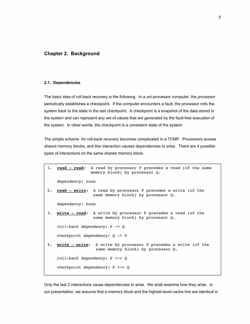
1. read Ð read: A read by processor P precedes a read (of the same memory block) by processor Q.
dependency: none
2. read Ð write: A read by processor P precedes a write (of the same memory block) by processor Q.
dependency: none
3. write Ð read: A write by processor P precedes a read (of the same memory block) by processor Q.
roll-back dependency: P -> Q
checkpoint dependency: Q -> P
4. write Ð write: A write by processor P precedes a write (of the same memory block) by processor Q.
roll-back dependency: P <-> Q
checkpoint dependency: P <-> Q
6
size and that the TCMP uses a write-back cache policy. To minimize the cost of the system, we
assume that it can hold only 1 level of checkpoint.
We use the notation of Ò->Ó or Ò<->Ó to indicate, respectively, that 1 processor is dependent on
another processor or that 2 processors are dependent on each other. For example, consider the
roll-back dependency of ÒP -> QÓ. This symbolic notation indicates that if processor ÒPÓ rolls
back to its last checkpoint, then processor ÒQÓ must also roll back to its last checkpoint.
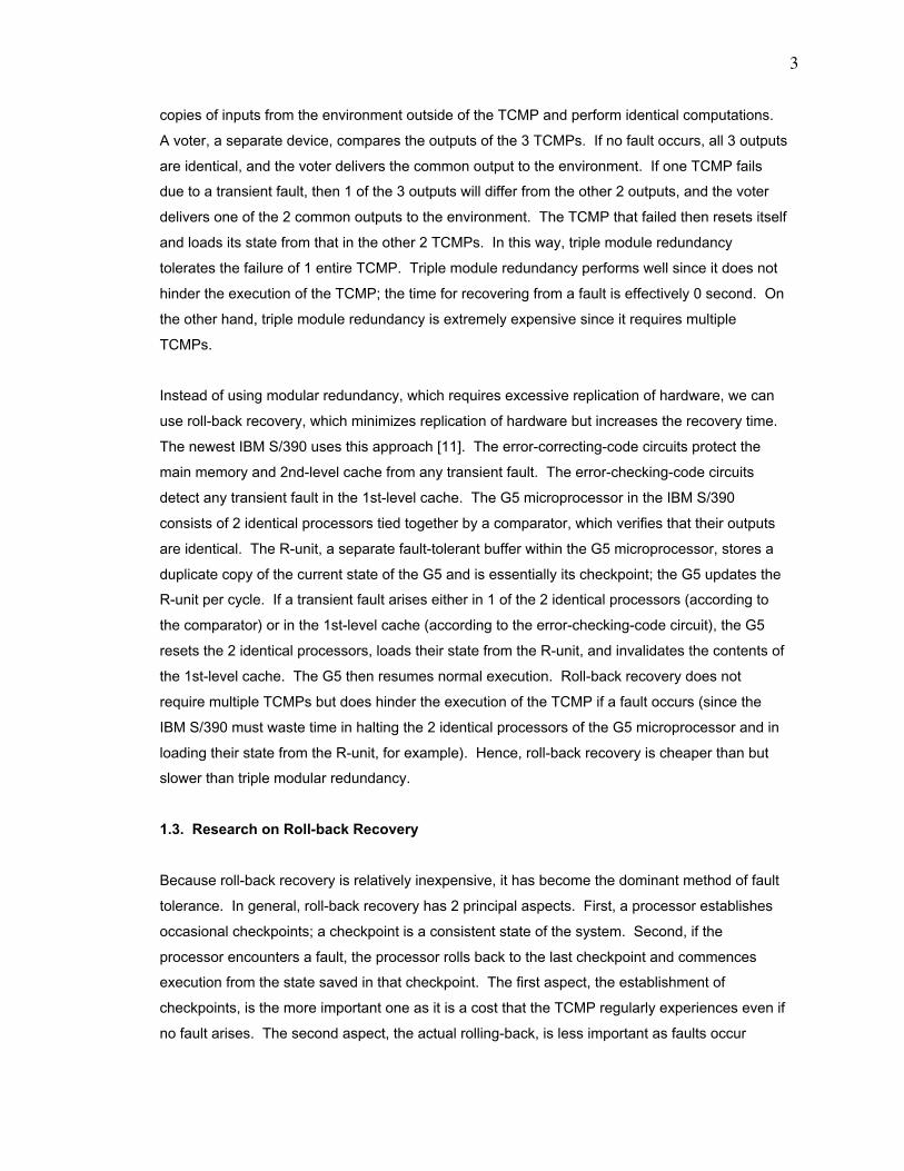
Figure 2 illustrates the roll-back dependency that arises for the write-read interaction. After
processor "P" writes the value of 1 into a word of the memory block, processor "Q" reads that
value of 1. Then, processor "P" experiences a fault and rolls back to the last checkpoint. "Q"
must also roll back to the last checkpoint because ÒQÓ read a value, 1 in this case, that "P"
produced. When "P" resumes execution from the last checkpoint, "P" may not necessarily
reproduce the value of 1. (ÒPÓ may not necessarily reproduce the value of 1 since ÒPÓ may not
necessarily read the same values that ÒPÓ read prior to the fault. Some other processor, say ÒRÓ,
may have already modified those values.) Thus, we have the roll-back dependency of "P -> Q".
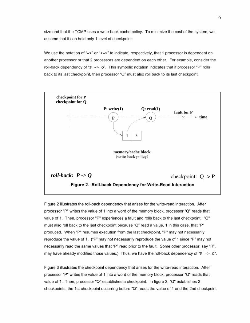
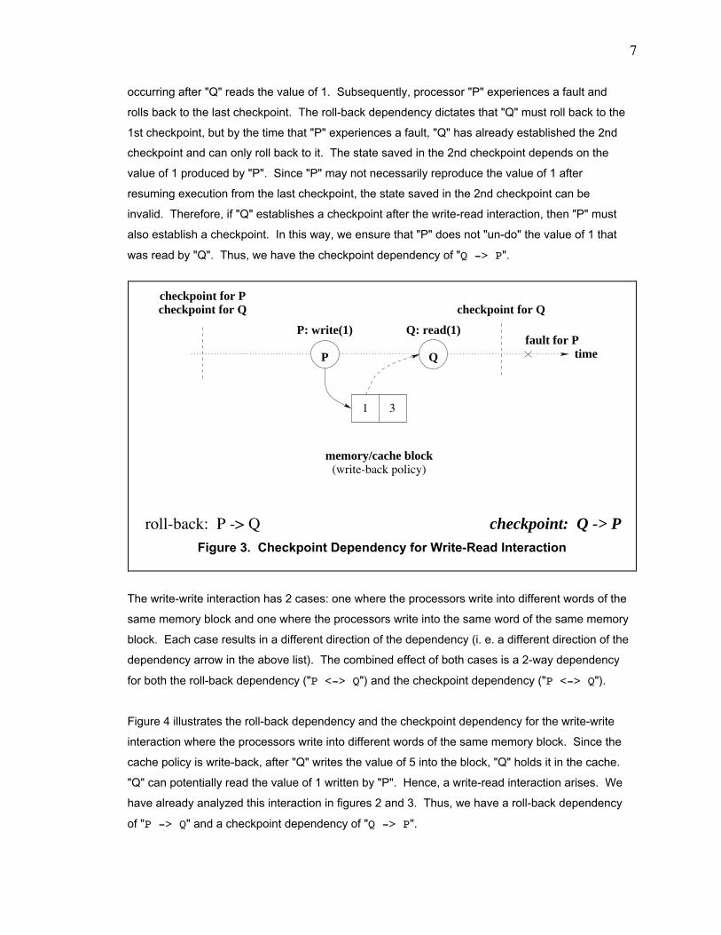
Figure 3 illustrates the checkpoint dependency that arises for the write-read interaction. After
processor "P" writes the value of 1 into a word of the memory block, processor "Q" reads that
value of 1. Then, processor "Q" establishes a checkpoint. In figure 3, "Q" establishes 2
checkpoints: the 1st checkpoint occurring before "Q" reads the value of 1 and the 2nd checkpoint
1 3
checkpoint: Q -> P
P Q time
(write-back policy)memory/cache block
P: write(1)
checkpoint for Qcheckpoint for P
Q: read(1)fault for P
roll-back: P -> Q
Figure 2. Roll-back Dependency for Write-Read Interaction
7
occurring after "Q" reads the value of 1. Subsequently, processor "P" experiences a fault and
rolls back to the last checkpoint. The roll-back dependency dictates that "Q" must roll back to the
1st checkpoint, but by the time that "P" experiences a fault, "Q" has already established the 2nd
checkpoint and can only roll back to it. The state saved in the 2nd checkpoint depends on the
value of 1 produced by "P". Since "P" may not necessarily reproduce the value of 1 after
resuming execution from the last checkpoint, the state saved in the 2nd checkpoint can be
invalid. Therefore, if "Q" establishes a checkpoint after the write-read interaction, then "P" must
also establish a checkpoint. In this way, we ensure that "P" does not "un-do" the value of 1 that
was read by "Q". Thus, we have the checkpoint dependency of "Q -> P".
The write-write interaction has 2 cases: one where the processors write into different words of the
same memory block and one where the processors write into the same word of the same memory
block. Each case results in a different direction of the dependency (i. e. a different direction of the
dependency arrow in the above list). The combined effect of both cases is a 2-way dependency
for both the roll-back dependency ("P <-> Q") and the checkpoint dependency ("P <-> Q").
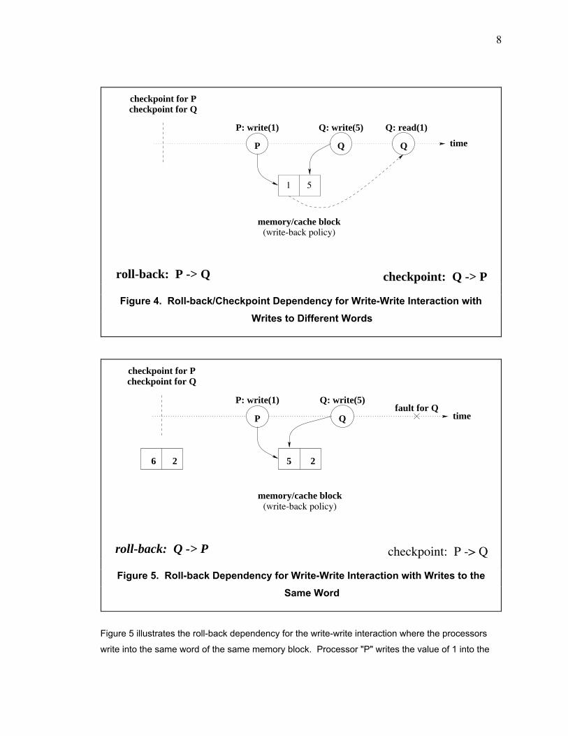
Figure 4 illustrates the roll-back dependency and the checkpoint dependency for the write-write
interaction where the processors write into different words of the same memory block. Since the
cache policy is write-back, after "Q" writes the value of 5 into the block, "Q" holds it in the cache.
"Q" can potentially read the value of 1 written by "P". Hence, a write-read interaction arises. We
have already analyzed this interaction in figures 2 and 3. Thus, we have a roll-back dependency
of "P -> Q" and a checkpoint dependency of "Q -> P".
1 3
checkpoint: Q -> P
P Q time
(write-back policy)memory/cache block
P: write(1)
checkpoint for Qcheckpoint for P
Q: read(1)fault for P
checkpoint for Q
roll-back: P -> Q
Figure 3. Checkpoint Dependency for Write-Read Interaction
8
Figure 5 illustrates the roll-back dependency for the write-write interaction where the processors
write into the same word of the same memory block. Processor "P" writes the value of 1 into the
1 5
checkpoint: Q -> P
P Q timeQ
Q: read(1)Q: write(5)P: write(1)
(write-back policy)memory/cache block
checkpoint for Pcheckpoint for Q
roll-back: P -> Q
Figure 4. Roll-back/Checkpoint Dependency for Write-Write Interaction with
Writes to Different Words
P Q
checkpoint: P -> Q
time
Q: write(5)P: write(1)
(write-back policy)memory/cache block
checkpoint for P
6 2 25
fault for Q
checkpoint for Q
roll-back: Q -> P
Figure 5. Roll-back Dependency for Write-Write Interaction with Writes to the
Same Word
9
memory block, overwriting the original value of "6". Then, processor "Q" writes the value of 5 into
the same word, overwriting the value of 1. Subsequently, "Q" experiences a fault and rolls back
to the last checkpoint. "Q" un-does the value of 5 and must replace it with the value of 1, but
there is no convenient way to retrieve the value of 1 since it was destroyed by "Q" writing the
value of 5. The only value that the TCMP can use to replace 5 is the original value of 6. In order
to ensure that the state of the TCMP is valid, "P" must roll-back to the last checkpoint as well in
order to un-do the value of 1. Hence, we have a roll-back dependency of "Q -> P".
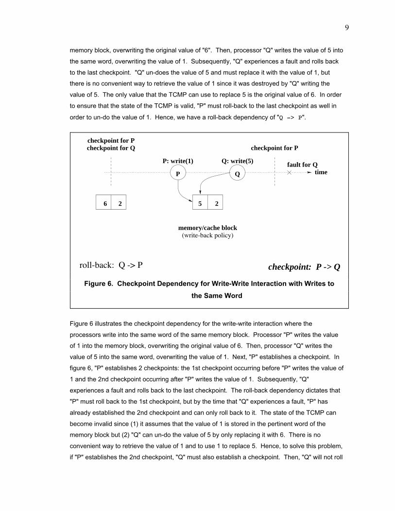
Figure 6 illustrates the checkpoint dependency for the write-write interaction where the
processors write into the same word of the same memory block. Processor "P" writes the value
of 1 into the memory block, overwriting the original value of 6. Then, processor "Q" writes the
value of 5 into the same word, overwriting the value of 1. Next, "P" establishes a checkpoint. In
figure 6, "P" establishes 2 checkpoints: the 1st checkpoint occurring before "P" writes the value of
1 and the 2nd checkpoint occurring after "P" writes the value of 1. Subsequently, "Q"
experiences a fault and rolls back to the last checkpoint. The roll-back dependency dictates that
"P" must roll back to the 1st checkpoint, but by the time that "Q" experiences a fault, "P" has
already established the 2nd checkpoint and can only roll back to it. The state of the TCMP can
become invalid since (1) it assumes that the value of 1 is stored in the pertinent word of the
memory block but (2) "Q" can un-do the value of 5 by only replacing it with 6. There is no
convenient way to retrieve the value of 1 and to use 1 to replace 5. Hence, to solve this problem,
if "P" establishes the 2nd checkpoint, "Q" must also establish a checkpoint. Then, "Q" will not roll
P Q
checkpoint: P -> Q
time
Q: write(5)P: write(1)
(write-back policy)memory/cache block
checkpoint for P
6 2 25
checkpoint for P
fault for Q
checkpoint for Q
roll-back: Q -> P
Figure 6. Checkpoint Dependency for Write-Write Interaction with Writes to
the Same Word
10
back past the 2nd checkpoint and will not need to un-do the value of 5. Thus, we have a
checkpoint dependency of "P -> Q".
Therefore, the write-write interaction causes bi-directional dependencies to arise. The roll-back
dependency is "P <-> Q". The checkpoint dependency is "P <-> Q" as well.
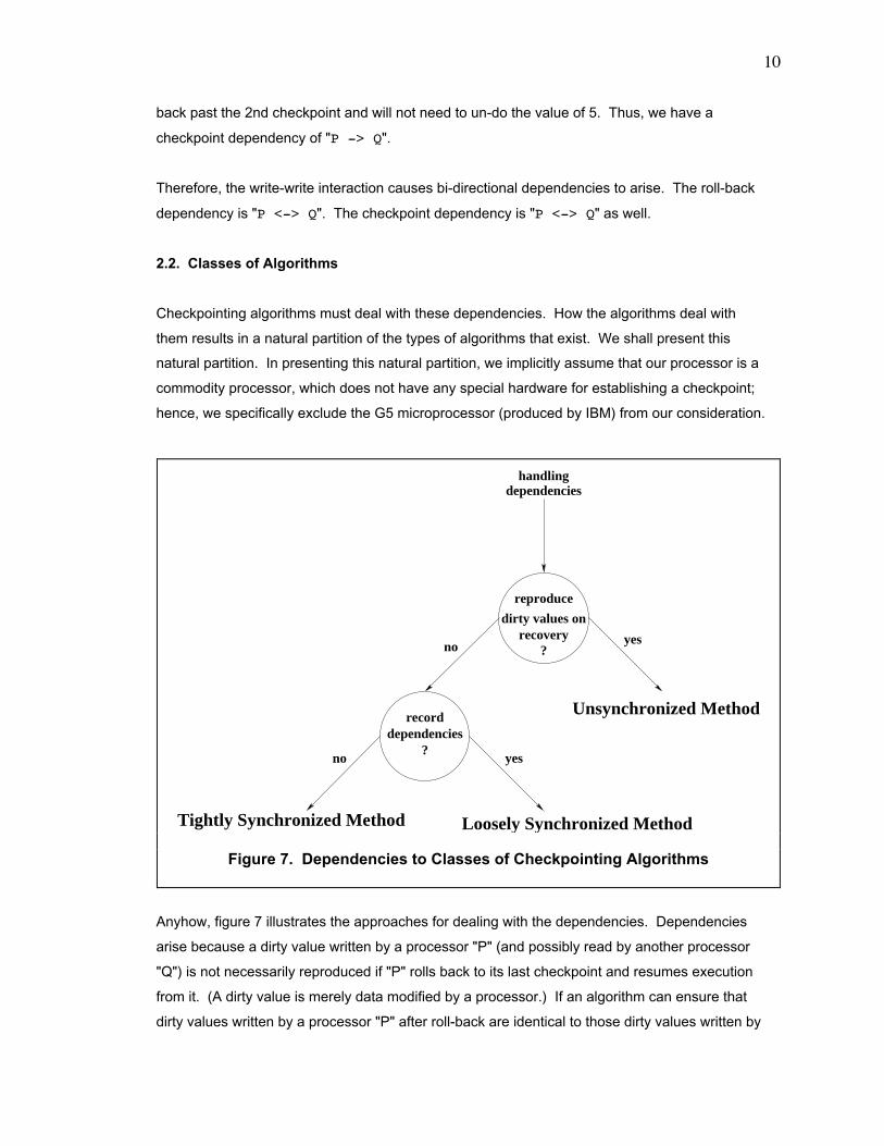
2.2. Classes of Algorithms
Checkpointing algorithms must deal with these dependencies. How the algorithms deal with
them results in a natural partition of the types of algorithms that exist. We shall present this
natural partition. In presenting this natural partition, we implicitly assume that our processor is a
commodity processor, which does not have any special hardware for establishing a checkpoint;
hence, we specifically exclude the G5 microprocessor (produced by IBM) from our consideration.
Anyhow, figure 7 illustrates the approaches for dealing with the dependencies. Dependencies
arise because a dirty value written by a processor "P" (and possibly read by another processor
"Q") is not necessarily reproduced if "P" rolls back to its last checkpoint and resumes execution
from it. (A dirty value is merely data modified by a processor.) If an algorithm can ensure that
dirty values written by a processor "P" after roll-back are identical to those dirty values written by
dirty values onrecovery
recorddependencies
?
reproduce
?yesno
Unsynchronized Method
Tightly Synchronized Method Loosely Synchronized Method
no yes
dependencieshandling
Figure 7. Dependencies to Classes of Checkpointing Algorithms
11
"P" before encountering the fault (that resulted in the roll-back), then the algorithm is a member of
the class called the unsynchronized method. In an algorithm in the class of the unsynchronized
method, a processor can establish a checkpoint (or perform a roll-back) that is completely
independent of any other processor.
If an algorithm cannot guarantee that dirty values produced by "P" after roll-back are identical to
those dirty values produced by "P" before encountering the fault, then the algorithm can simply
record the dependencies. Such an algorithm is a member of the class called the loosely
synchronized method. In an algorithm in the class of the loosely synchronized method, if any
checkpoint dependency (or roll-back dependency) arises, the TCMP simply records the
dependency. At some point in the future, if a processor establishes a checkpoint (or performs a
roll-back), then that processor queries the records of dependencies to determine all other
processors that must establish a checkpoint (or perform a roll-back) as well.
Finally, if the checkpointing algorithm cannot guarantee reproduction of dirty values after roll-back
and if the algorithm does not record dependencies, then the algorithm must do following. A
processor "P" must establish a checkpoint whenever "P" delivers dirty data to another processor
or to the memory system (via the eviction of a dirty cache line). Such an algorithm is a member
of the class called the tightly synchronized method.
For a TCMP, researchers have developed algorithms in the class of the tightly synchronized
method and in the class of the loosely synchronized method. An example of an algorithm in the
class of the tightly synchronized method is the algorithm proposed by Wu [17]. An example of an
algorithm in the class of the loosely synchronized method is the algorithm proposed by Banatre
[2].
As for our algorithms in this dissertation, DRSM-C is an algorithm in the class of the tightly
synchronized method. Both DRSM and DRSM-H are algorithms in the class of the loosely
synchronized method. DRSM-L is an algorithm in the class of the unsynchronized method and is
the first algorithm in the class of the unsynchronized method for a TCMP. Before DRSM-L, no
such algorithm for a TCMP existed although Richard [10] and Suri [15] have proposed algorithms
in the class of the unsynchronized method for a loosely-coupled multiprocessor like a network of
workstations. The DRSM-L described here is an improved version of DRSM-L originally contrived
by Sunada [13].
12
Chapter 3. Assumptions
3.1. Fault-tolerant Components
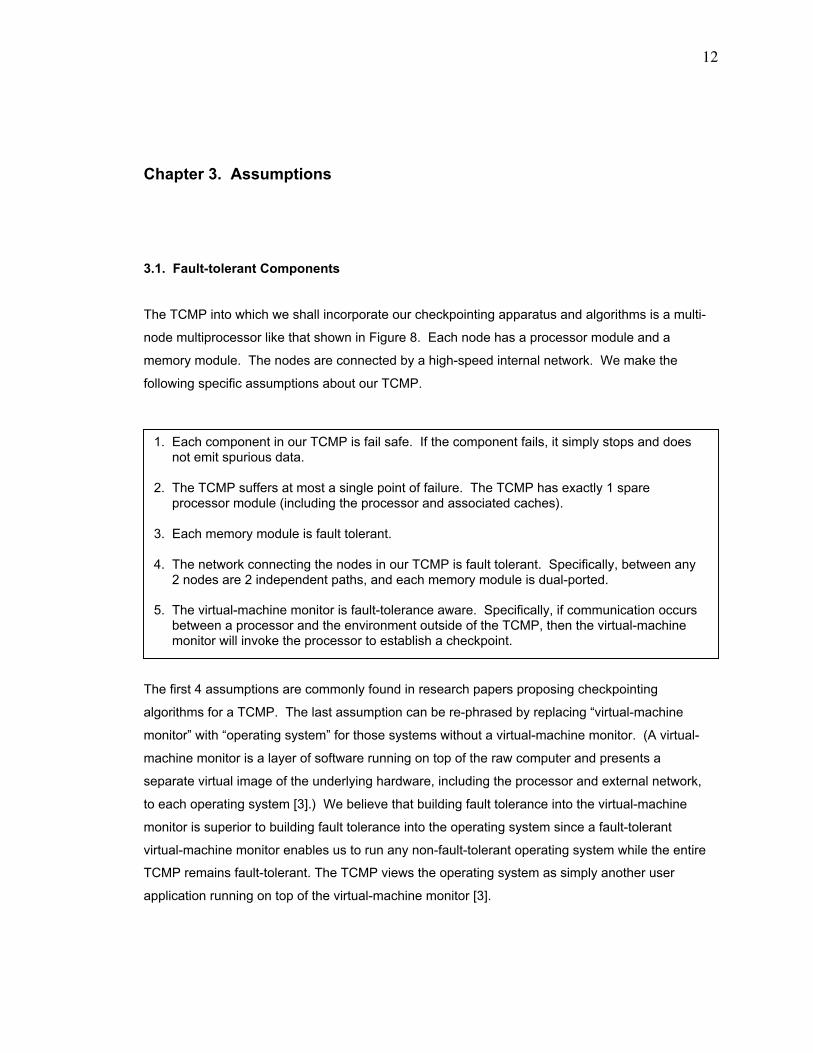
The TCMP into which we shall incorporate our checkpointing apparatus and algorithms is a multi-
node multiprocessor like that shown in Figure 8. Each node has a processor module and a
memory module. The nodes are connected by a high-speed internal network. We make the
following specific assumptions about our TCMP.
The first 4 assumptions are commonly found in research papers proposing checkpointing
algorithms for a TCMP. The last assumption can be re-phrased by replacing Òvirtual-machine
monitorÓ with Òoperating systemÓ for those systems without a virtual-machine monitor. (A virtual-
machine monitor is a layer of software running on top of the raw computer and presents a
separate virtual image of the underlying hardware, including the processor and external network,
to each operating system [3].) We believe that building fault tolerance into the virtual-machine
monitor is superior to building fault tolerance into the operating system since a fault-tolerant
virtual-machine monitor enables us to run any non-fault-tolerant operating system while the entire
TCMP remains fault-tolerant. The TCMP views the operating system as simply another user
application running on top of the virtual-machine monitor [3].
1. Each component in our TCMP is fail safe. If the component fails, it simply stops and doesnot emit spurious data.
2. The TCMP suffers at most a single point of failure. The TCMP has exactly 1 spareprocessor module (including the processor and associated caches).
3. Each memory module is fault tolerant.
4. The network connecting the nodes in our TCMP is fault tolerant. Specifically, between any2 nodes are 2 independent paths, and each memory module is dual-ported.
5. The virtual-machine monitor is fault-tolerance aware. Specifically, if communication occursbetween a processor and the environment outside of the TCMP, then the virtual-machinemonitor will invoke the processor to establish a checkpoint.
13
Also, our assumption that the TCMP suffers at most a single point of failure is overly restrictive for
both DRSM-C and DRSM-L. The recovery algorithms that we describe for DRSM-C and DRSM-L
actually allow them to recover from multiple transient faults (but only a single permanent fault
since we assume only 1 spare processor module).
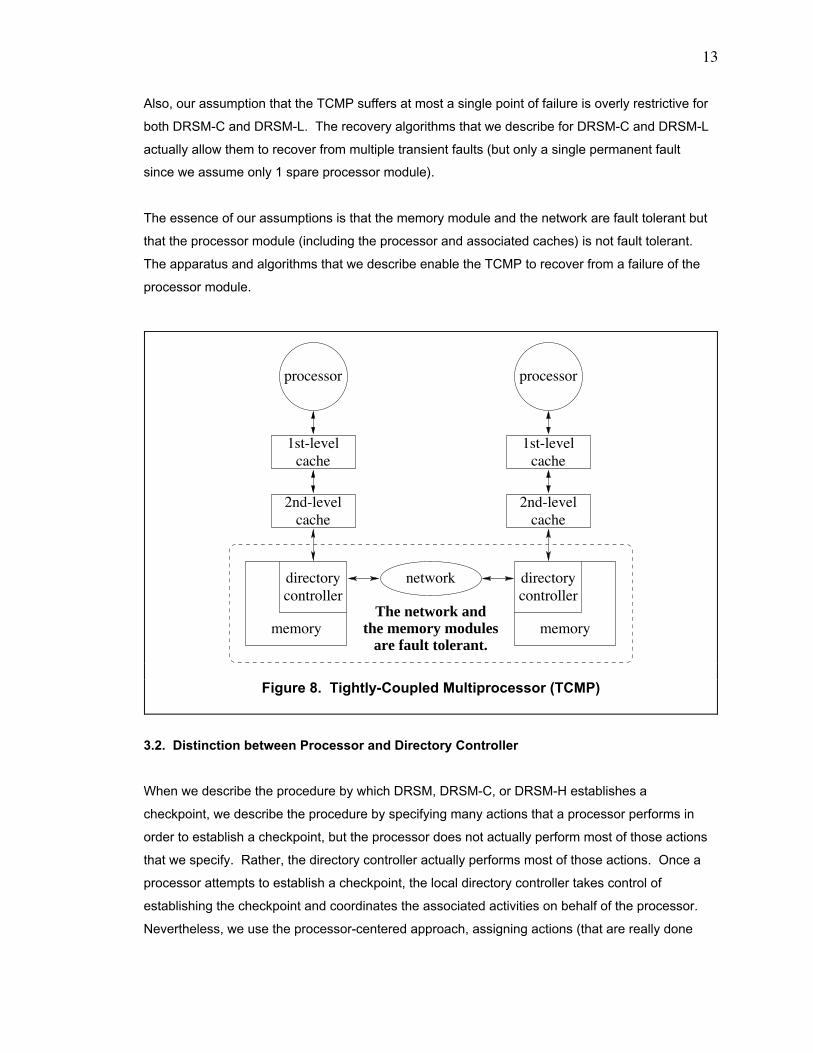
The essence of our assumptions is that the memory module and the network are fault tolerant but
that the processor module (including the processor and associated caches) is not fault tolerant.
The apparatus and algorithms that we describe enable the TCMP to recover from a failure of the
processor module.
3.2. Distinction between Processor and Directory Controller
When we describe the procedure by which DRSM, DRSM-C, or DRSM-H establishes a
checkpoint, we describe the procedure by specifying many actions that a processor performs in
order to establish a checkpoint, but the processor does not actually perform most of those actions
that we specify. Rather, the directory controller actually performs most of those actions. Once a
processor attempts to establish a checkpoint, the local directory controller takes control of
establishing the checkpoint and coordinates the associated activities on behalf of the processor.
Nevertheless, we use the processor-centered approach, assigning actions (that are really done
2nd-level
the memory modules
cache2nd-level
cache
processor processor
1st-levelcache
1st-levelcache
networkdirectorycontroller
memory memory
controllerdirectory
The network and
are fault tolerant.
Figure 8. Tightly-Coupled Multiprocessor (TCMP)
14
by the directory controller) to the processor, to describe the checkpointing procedure because this
approach simplifies the description.
15
Chapter 4. Distributed Recoverable Shared Memory (DRSM)
4.1. Introduction
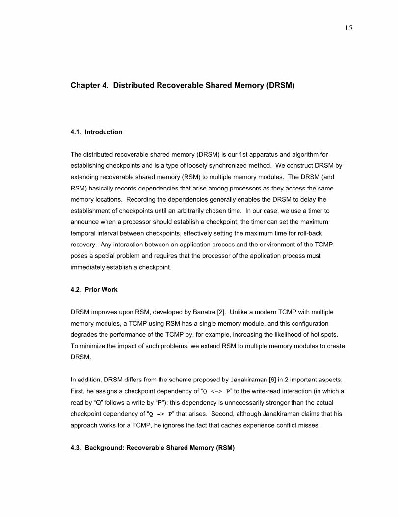
The distributed recoverable shared memory (DRSM) is our 1st apparatus and algorithm for
establishing checkpoints and is a type of loosely synchronized method. We construct DRSM by
extending recoverable shared memory (RSM) to multiple memory modules. The DRSM (and
RSM) basically records dependencies that arise among processors as they access the same
memory locations. Recording the dependencies generally enables the DRSM to delay the
establishment of checkpoints until an arbitrarily chosen time. In our case, we use a timer to
announce when a processor should establish a checkpoint; the timer can set the maximum
temporal interval between checkpoints, effectively setting the maximum time for roll-back
recovery. Any interaction between an application process and the environment of the TCMP
poses a special problem and requires that the processor of the application process must
immediately establish a checkpoint.
4.2. Prior Work
DRSM improves upon RSM, developed by Banatre [2]. Unlike a modern TCMP with multiple
memory modules, a TCMP using RSM has a single memory module, and this configuration
degrades the performance of the TCMP by, for example, increasing the likelihood of hot spots.
To minimize the impact of such problems, we extend RSM to multiple memory modules to create
DRSM.
In addition, DRSM differs from the scheme proposed by Janakiraman [6] in 2 important aspects.
First, he assigns a checkpoint dependency of ÒQ <-> PÓ to the write-read interaction (in which a
read by ÒQÓ follows a write by ÒP"); this dependency is unnecessarily stronger than the actual
checkpoint dependency of ÒQ -> PÓ that arises. Second, although Janakiraman claims that his
approach works for a TCMP, he ignores the fact that caches experience conflict misses.
4.3. Background: Recoverable Shared Memory (RSM)
16
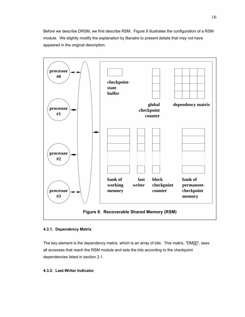
Before we describe DRSM, we first describe RSM. Figure 9 illustrates the configuration of a RSM
module. We slightly modify the explanation by Banatre to present details that may not have
appeared in the original description.
4.3.1. Dependency Matrix
The key element is the dependency matrix, which is an array of bits. This matrix, "DM[][]", sees
all accesses that reach the RSM module and sets the bits according to the checkpoint
dependencies listed in section 2.1.
4.3.2. Last-Writer Indicator
counter
processor
processor
processor
processor#2
#1
#0
#3
statebuffer
dependency matrix
blockcheckpointcounter
checkpoint-
bank of bank of
memory checkpointmemory
working permanent-last
writer
globalcheckpoint
Figure 9. Recoverable Shared Memory (RSM)
17
The RSM module contains an additional buffer for each block of memory. This buffer stores the
last writer to the block.
4.3.3. Checkpoint Counters
The collection of global checkpoint counters contains 1 counter for each processor in the system.
Each block in memory has an associated block checkpoint counter. When processor "P[2]", for
example, writes into a block, the value of the global checkpoint counter for "P[2]" is copied into
the block checkpoint counter. RSM updates the buffer for the last writer to "2". The purpose of
the checkpoint counters is to accelerate the establishment of permanent checkpoints. They are
explained in a later section.
4.3.4. Memory for Tentative Checkpoint
The working memory operates like the memory in a non-fault-tolerant system but also functions
as the tentative-checkpoint memory. When the RSM begins a 2-phase checkpoint of dependent
processors, they write their dirty cache data into the tentative-checkpoint memory in the 1st
phase. The dirty blocks of memory form the tentative checkpoint, which is later converted into the
permanent checkpoint in the 2nd phase.
4.3.5. Memory for Permanent Checkpoint
The RSM ultimately copies data saved during the tentative-checkpoint phase into the permanent-
checkpoint memory. It always contains data comprising a consistent state of the system. The
TCMP rolls back to this data after a failure occurs.
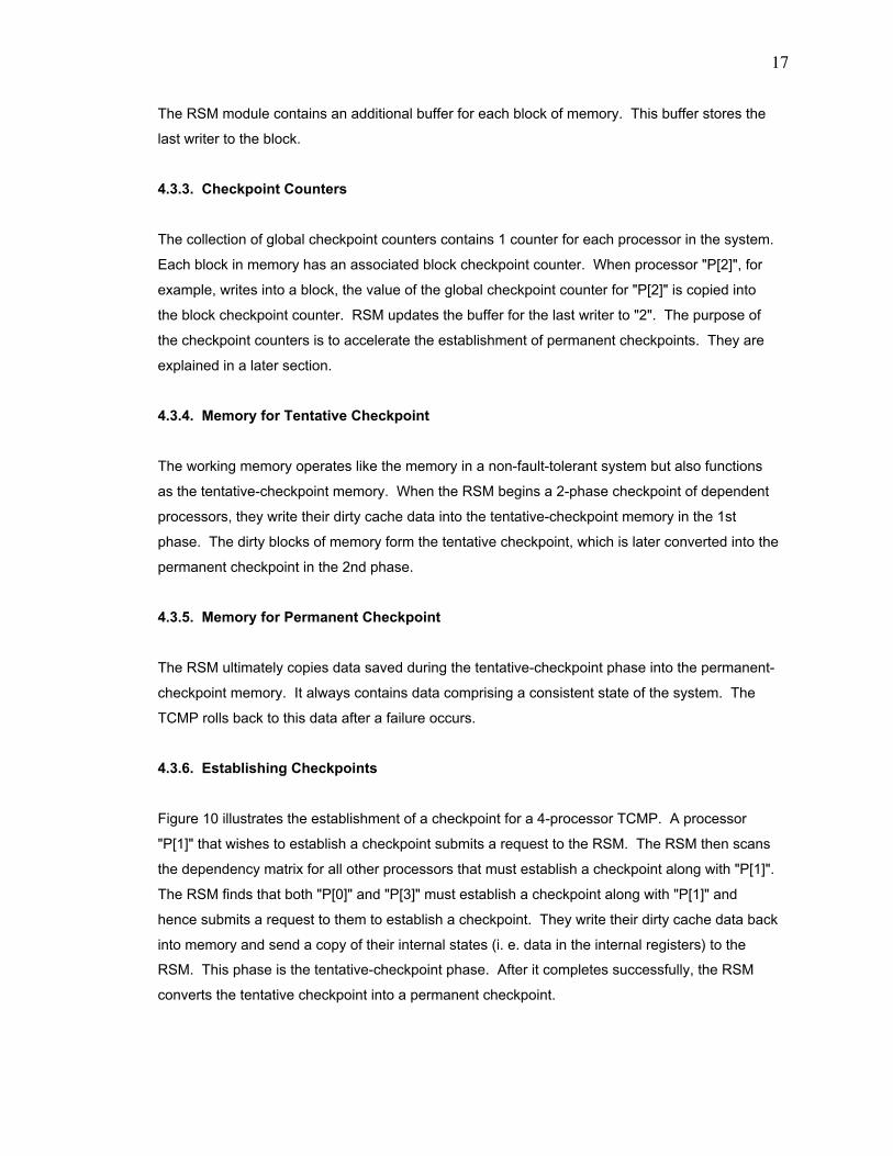
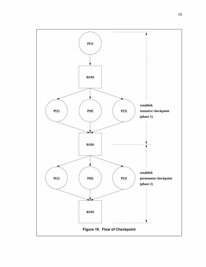
4.3.6. Establishing Checkpoints
Figure 10 illustrates the establishment of a checkpoint for a 4-processor TCMP. A processor
"P[1]" that wishes to establish a checkpoint submits a request to the RSM. The RSM then scans
the dependency matrix for all other processors that must establish a checkpoint along with "P[1]".
The RSM finds that both "P[0]" and "P[3]" must establish a checkpoint along with "P[1]" and
hence submits a request to them to establish a checkpoint. They write their dirty cache data back
into memory and send a copy of their internal states (i. e. data in the internal registers) to the
RSM. This phase is the tentative-checkpoint phase. After it completes successfully, the RSM
converts the tentative checkpoint into a permanent checkpoint.
18
(phase 2)
RSM
P[1]
P[0] P[3]
RSM
P[0] P[3]
RSM
P[1]
P[1]
establish
tentative checkpoint
(phase 1)
establish
permanent checkpoint
Figure 10. Flow of Checkpoint
19
After verifying that the establishment of the tentative checkpoint is successful, the RSM
increments the global checkpoint counters for "P[0]", "P[1]", and "P[3]" and then requests those
processors to resume execution of their normal processes. They send acknowledgments to the
RSM, and it resumes its normal functions. The RSM does not immediately copy the blocks saved
during the tentative-checkpoint phase into the permanent-checkpoint memory during the
permanent-checkpoint phase. Rather, the RSM merely increments the global checkpoint
counters for the processors involved in the checkpoint. After the RSM concludes the permanent
checkpoint, if a write access occurs on a block (in the tentative-checkpoint memory) where the
global checkpoint counter of the last writer is greater than the block counter, then the RSM knows
that the current data in the block is part of a permanent checkpoint. Hence, the RSM first copies
the data from the block in the tentative-checkpoint memory into the corresponding block in the
permanent-checkpoint memory before the RSM writes the incoming new data into the block in the
tentative-checkpoint memory. This copy-on-write technique accelerates the establishment of the
permanent checkpoint by avoiding the copying of potentially millions of blocks of data from the
tentative-checkpoint memory into the permanent-checkpoint memory during the permanent-
checkpoint phase.
4.3.7. New Requests after Initiating Checkpoint
If processor "P[2]" submits a request to the RSM to establish a checkpoint and if the request
arrives at the RSM before the start of the permanent-checkpoint phase for "P[0]", "P[1]", and
"P[3]", then the RSM will combine "P[2]" into the group of processors that must establish a
checkpoint together. In other words, the RSM grants the request from "P[2]" to establish a
checkpoint and waits until "P[2]" has finished its tentative-checkpoint phase before the RSM
begins the permanent-checkpoint phase of all processors in the group: "P[0]", "P[1]", "P[2]", and
"P[3]". If the request arrives after the start of the permanent-checkpoint phase, then the RSM
negatively acknowledges the request, and "P[2]" must re-submit its request.
4.4. Apparatus of DRSM
We extend RSM to multiple memory modules to create distributed recoverable shared memory
(DRSM). The single memory module of RSM degrades the performance of the TCMP by, for
example, increasing the likelihood of hot spots. Modern TCMPs distribute the shared memory
among all the nodes in the system.
20
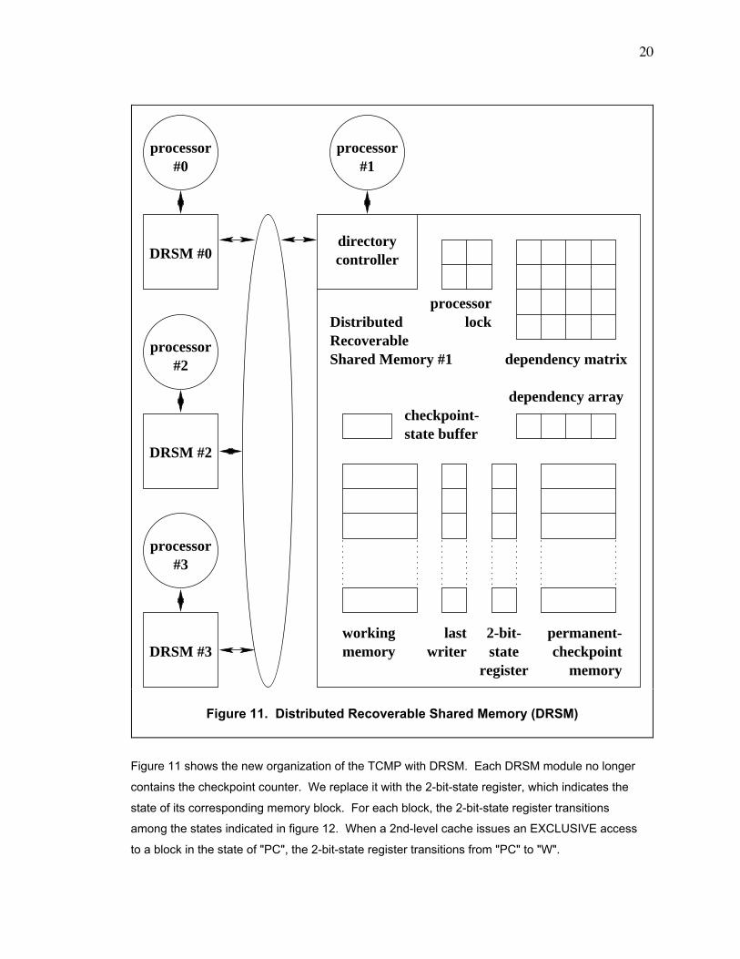
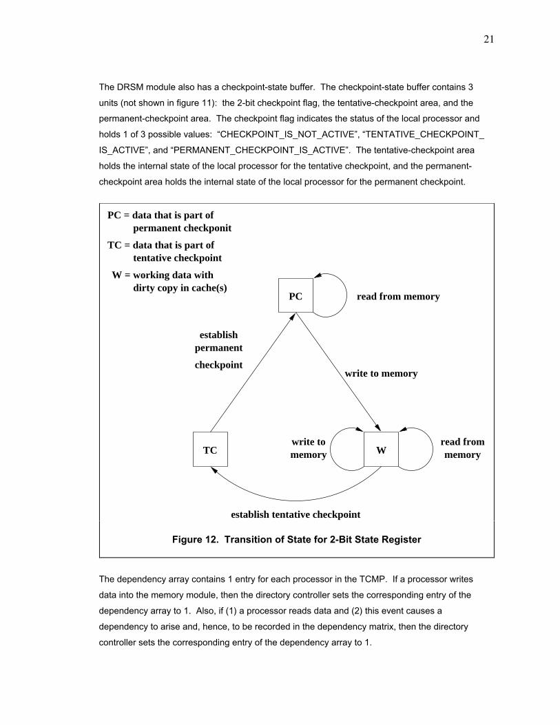
Figure 11 shows the new organization of the TCMP with DRSM. Each DRSM module no longer
contains the checkpoint counter. We replace it with the 2-bit-state register, which indicates the
state of its corresponding memory block. For each block, the 2-bit-state register transitions
among the states indicated in figure 12. When a 2nd-level cache issues an EXCLUSIVE access
to a block in the state of "PC", the 2-bit-state register transitions from "PC" to "W".
state buffer
directorycontrollerDRSM #0
processor#1
processor#0
DRSM #2
processor#2
DRSM #3
processor#3
2-bit-state
register
dependency matrix
dependency array
processor
permanent-checkpoint
memory
workingmemory
DistributedRecoverableShared Memory #1
lock
lastwriter
checkpoint-
Figure 11. Distributed Recoverable Shared Memory (DRSM)
21
The DRSM module also has a checkpoint-state buffer. The checkpoint-state buffer contains 3
units (not shown in figure 11): the 2-bit checkpoint flag, the tentative-checkpoint area, and the
permanent-checkpoint area. The checkpoint flag indicates the status of the local processor and
holds 1 of 3 possible values: ÒCHECKPOINT_IS_NOT_ACTIVEÓ, ÒTENTATIVE_CHECKPOINT_
IS_ACTIVEÓ, and ÒPERMANENT_CHECKPOINT_IS_ACTIVEÓ. The tentative-checkpoint area
holds the internal state of the local processor for the tentative checkpoint, and the permanent-
checkpoint area holds the internal state of the local processor for the permanent checkpoint.
The dependency array contains 1 entry for each processor in the TCMP. If a processor writes
data into the memory module, then the directory controller sets the corresponding entry of the
dependency array to 1. Also, if (1) a processor reads data and (2) this event causes a
dependency to arise and, hence, to be recorded in the dependency matrix, then the directory
controller sets the corresponding entry of the dependency array to 1.
PC
TC Wwrite tomemory
read from
dirty copy in cache(s)
memory
read from memory
write to memory
establish tentative checkpoint
establish
checkpoint
permanent
tentative checkpoint
permanent checkponitPC = data that is part of
TC = data that is part of
W = working data with
Figure 12. Transition of State for 2-Bit State Register

22
In figure 11, the structure with the label of Òprocessor lockÓ contains 1 lock per processor in the
TCMP. The DRSM module sets the processor lock to "1" if a processor querying the memory
module during the establishment of the tentative checkpoint has an entry of Ò1Ó in the dependency
array; an entry of Ò1Ó in the dependency array indicates that the processor (1) is a writer of a dirty
block in the memory module or (2) has dependent processors, according to the dependency
matrix. During the establishment of the permanent checkpoint, if an incoming memory access
originates from a processor with its processor lock being "1", the DRSM module negatively
acknowledges that request. This action prevents a race from developing on the dependency
matrix.
One example of a race is the following. Suppose that processor "P[1]" finishes its permanent
checkpoint before a memory module "DRSM[2]" completes its permanent checkpoint and that
"P[1]" has its processor lock being "1" in "DRSM[2]". Suppose that "P[3]" writes into a memory
block (in "DRSM[2]") that is not part of the checkpoint which is just completing. Then, processor
"P[1]" reads that same block before "DRSM[2]" completes its permanent checkpoint. The
dependency "P[1] -> P[3]" will be lost when "DRSM[2]" completes its permanent checkpoint,
clearing the row and column (of the dependency matrix) containing "P[1]".
4.5. Triggers of Checkpoint Establishment
Two events can trigger the establishment of a checkpoint.
4.6. Establishing Tentative Checkpoints
4.6.1. General Overview
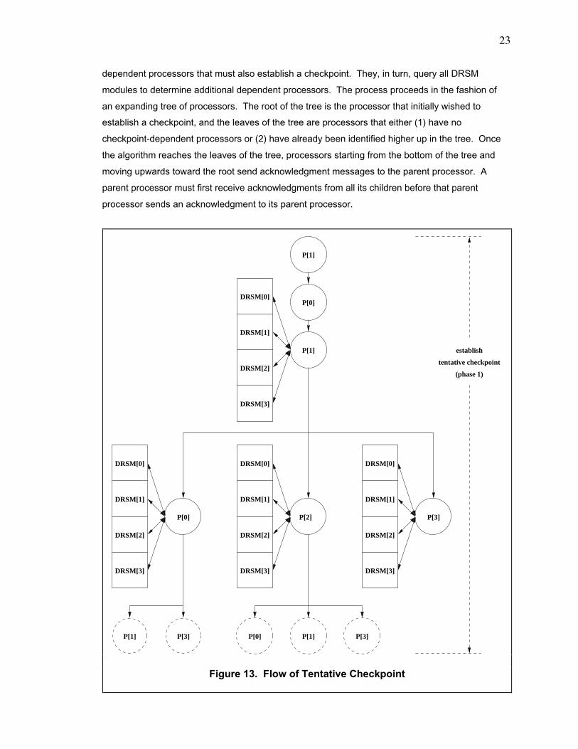
Unlike RSM, DRSM has several memory modules, so we must radically modify the algorithm for
establishing a tentative checkpoint. Figure 13 shows the new algorithm. Its general strategy is
that a processor wishing to establish a checkpoint must query all DRSM modules to determine all
1. timer-triggered checkpoint: A timer expires. When the timer fora processor expires, it establishes a checkpoint. The timerensures a maximum bound on the time interval between checkpoints.
2. external-communication-triggered checkpoint: Communicationoccurs between a processor and the environment outside of theTCMP. When data leaves or enters a TCMP, the processor handlingthe data must establish a checkpoint. Communication includesinterrupts.
23
dependent processors that must also establish a checkpoint. They, in turn, query all DRSM
modules to determine additional dependent processors. The process proceeds in the fashion of
an expanding tree of processors. The root of the tree is the processor that initially wished to
establish a checkpoint, and the leaves of the tree are processors that either (1) have no
checkpoint-dependent processors or (2) have already been identified higher up in the tree. Once
the algorithm reaches the leaves of the tree, processors starting from the bottom of the tree and
moving upwards toward the root send acknowledgment messages to the parent processor. A
parent processor must first receive acknowledgments from all its children before that parent
processor sends an acknowledgment to its parent processor.
tentative checkpoint
DRSM[0]
DRSM[1]
DRSM[2]
DRSM[3]
P[3]
P[1] P[3]
DRSM[0]
DRSM[1]
DRSM[2]
DRSM[3]
P[0]
P[1]
P[0]
P[1]
P[0] P[1] P[3]
DRSM[0]
DRSM[1]
DRSM[2]
DRSM[3]
P[2]
DRSM[0]
DRSM[1]
DRSM[2]
DRSM[3]
establish
(phase 1)
Figure 13. Flow of Tentative Checkpoint

24
4.6.2. Details
As a specific example, we trace the flow in figure 13 for a 4-processor TCMP. We arbitrarily
select processor "P[0]" to act as an arbiter to allow at most one tentative checkpoint to be
established at any time. "P[1]" submits a request to "P[0]" to obtain permission to establish a
checkpoint. "P[0]" grants the request, and "P[1]" proceeds to establish a tentative checkpoint (in
the first phase).
"P[1]" queries all the DRSM modules. They search their dependency matrices to find all
processors which must establish a checkpoint along with "P[1]". The DRSM modules send their
replies back to "P[1]". From their replies, "P[1]" discovers that "P[0]", "P[2]", and "P[3]" must
establish checkpoints. "P[1]" requests all of them to establish tentative checkpoints. In this
example, "P[0]", "P[2]", and "P[3]" receive the request from "P[1]" at approximately the same time
(although this situation need not always arise).
"P[0]" then queries all the DRSM modules to find that both "P[1]" and "P[3]" are dependent upon
it. "P[0]" requests them to establish tentative checkpoints. Upon receiving this request from
"P[0]", both "P[1]" and "P[3]" respond that they have already joined the checkpoint tree and are,
hence, leaves in this tree.
After receiving the request from "P[1], "P[2]" then queries all the DRSM modules to find that
"P[0]", "P[1]", and "P[3]" are dependent upon it. "P[2]" requests them to establish tentative
checkpoints. Upon receiving this request from "P[2]", all 3 processors Ð "P[0]", "P[1]", and "P[3]"
Ð respond that they have already joined the checkpoint tree and are, hence, leaves in this tree.
Finally, after receiving the request from "P[1]", "P[3]" then queries all the DRSM modules to find
that no processors are dependent on it. Hence, "P[3]" is a leaf in this tree. After "P[3]" completes
its tentative checkpoint, "P[3]" sends an acknowledgment back to "P[1]".
After "P[0]" completes its tentative checkpoint, "P[0]" sends an acknowledgment back to "P[1]".
After "P[2]" completes its tentative checkpoint, "P[2]" sends an acknowledgment back to "P[1]".
After "P[1]" receives acknowledgments from "P[0]", "P[2]", and "P[3]", "P[1]" concludes the
establishment of the tentative checkpoint, which is phase #1.
Figure 13 shows the general flow in the process of establishing a tentative checkpoint but omits 6
important details. They are the following.
25
4.6.3. Dependent Processors and Dependent DRSM Modules
The acknowledgments that are propagated from the leaves of the checkpoint tree up to the root in
figure 13 lists the dependent processors. Each processor in the tree determines processors that
are checkpoint dependent upon itself, packages this information along with all dependent-
processor information from the child processors, and passes this package of information in an
acknowledgment to the parent processor. In the end, the root processor is aware of all
dependent processors in the entire tree.
1. Before a processor queries all DRSM modules (in order to determine dependentprocessors), it (1) waits until all its pending cache operations are finished or negativelyacknowledged and (2) then writes all dirty cache data back into memory. The processorwaits for the DRSM modules to acknowledge that all the write-backs are complete.
2. Each processor sends a copy of its state (i. e. data in the internal registers) to thecheckpoint-state buffer of the DRSM module that is local to the processor.
3. A DRSM module that receives a query (to determine dependent processors) waits until allpending memory operations by the directory controller are finished before the DRSMmodule replies (with information about dependent processors) to the querying processor.During this waiting period, the DRSM module negatively acknowledges all requests that itreceives.
4. Just before the DRSM module replies to the querying processor, the DRSM module scansfor all memory blocks (in the working bank of memory) where (1) the state is "W" and (2)the last writer is the querying processor. If such memory blocks exist, then the DRSMmodule transitions the state from "W" to "TC". The DRSM module negativelyacknowledges accesses to blocks for which the state is ÒTCÓ. Locking out accesses tosuch blocks prevents changes in the checkpoint dependencies of the processors that havealmost completed the tentative checkpoint.
5. In addition, the DRSM module sets the processor lock of the querying processor to "1" ifthe corresponding entry in the dependency array is Ò1Ó. The DRSM module negativelyacknowledges normal memory accesses originating from a processor with its processorlock being "1". The aim is to prevent a race condition from developing in the dependencymatrix when the processor finishes its permanent checkpoint before the DRSM modulefinishes its own permanent checkpoint.
6. Just before the root processor of the checkpoint tree begins the establishment of thetentative checkpoint, that processor sets a 2-bit checkpoint flag in the checkpoint-statebuffer of the local memory module to indicate that the establishment of the tentativecheckpoint is active. The state of the checkpoint flag can be 1 of {CHECKPOINT_IS_NOT_ACTIVE, TENTATIVE_CHECKPOINT_IS_ACTIVE, PERMANENT_CHECKPOINT_IS_ACTIVE}. In figure 13, processor "P[1]" sets the checkpoint flag to "TENTATIVE_CHECKPOINT_IS_ACTIVE". The TCMP uses this state information to determine what todo in the event that a fault occurs during the establishment of a checkpoint.
26
The tree also propagates information about dependent DRSM modules to the root processors. A
DRSM module is a dependent DRSM module if the entry for the querying processor in the
dependency array is set to Ò1Ó.
When the DRSM module replies (with information about the dependent processors) to the
querying processor, the DRSM module also sends information (to the querying processor)
indicating whether the module is a dependent memory module. The querying processor
propagates this information about dependent DRSM modules back up to the root processor of the
checkpoint tree.
4.7. Establishing Permanent Checkpoints
4.7.1. General Overview
Figure 14 shows the new algorithm for establishing a permanent checkpoint for a 4-processor
TCMP. The general strategy is that the root processor in the checkpoint tree for the tentative
checkpoint guides the establishment of the permanent checkpoint. The root processor requests
all dependent processors and all dependent DRSM modules to establish a permanent
checkpoint. Once they complete their permanent checkpoint, they send acknowledgments to the
root processor. It then completes its own permanent checkpoint and sends an acknowledgment
to the arbiter processor. It removes the root processor from the queue.
4.7.2. Details
As a specific illustration, we trace the flow in figure 14. "P[1]" is the root processor of the
checkpoint tree for the tentative checkpoint. From it, "P[1]" knows that "P[0]", "P[2]", and "P[3]
are dependent processors and that "DRSM[0]", "DRSM[1]" , and "DRSM[3]" are dependent
DRSM modules. In this particular example, "DRSM[2]" is not a dependent DRSM module. "P[1]"
tells all dependent processors and DRSM modules to establish a permanent checkpoint.
Each of "DRSM[0]", "DRSM[1]", and "DRSM[3]" performs the following. The DRSM module
resets (to 0) all columns and all rows (in the dependency matrix) containing any processor with its
processor lock being "1". Next, the DRSM module identifies all blocks (in the working memory)
for which their states are "TC". The DRSM module transitions their states to "PC" and copies the
contents of the blocks from the working memory into the corresponding blocks in the permanent-
checkpoint memory. Finally, the DRSM module sends an acknowledgment to the root processor.
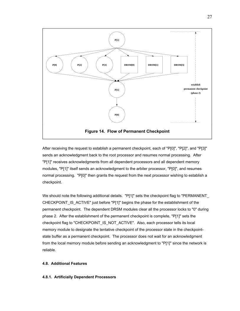
27
After receiving the request to establish a permanent checkpoint, each of "P[0]", "P[2]", and "P[3]"
sends an acknowledgment back to the root processor and resumes normal processing. After
"P[1]" receives acknowledgments from all dependent processors and all dependent memory
modules, "P[1]" itself sends an acknowledgment to the arbiter processor, "P[0]", and resumes
normal processing. "P[0]" then grants the request from the next processor wishing to establish a
checkpoint.
We should note the following additional details. "P[1]" sets the checkpoint flag to "PERMANENT_
CHECKPOINT_IS_ACTIVE" just before "P[1]" begins the phase for the establishment of the
permanent checkpoint. The dependent DRSM modules clear all the processor locks to "0" during
phase 2. After the establishment of the permanent checkpoint is complete, "P[1]" sets the
checkpoint flag to "CHECKPOINT_IS_NOT_ACTIVE". Also, each processor tells its local
memory module to designate the tentative checkpoint of the processor state in the checkpoint-
state buffer as a permanent checkpoint. The processor does not wait for an acknowledgment
from the local memory module before sending an acknowledgment to "P[1]" since the network is
reliable.
4.8. Additional Features
4.8.1. Artificially Dependent Processors
permanent checkpoint
P[0] P[2] P[3]
P[0]
P[1]
P[1]
DRSM[0] DRSM[1] DRSM[3]
establish
(phase 2)
Figure 14. Flow of Permanent Checkpoint
28
If the establishment of a checkpoint is in progress, the arbiter queues requests from processors
that request permission to establish a checkpoint. After the arbiter receives an acknowledgment
that the establishment of the current checkpoint is complete, the arbiter grants the next processor
(waiting in the checkpoint-request queue) permission to establish a checkpoint. There can be
many processors waiting in the queue.
If more than 1 processor waits in the queue, the arbiter grants permission to the processor at the
front of the queue but requests that processor, say "P[1]", to artificially treat all the other
processors (in the queue) as being dependent on it. After "P[1]" finishes querying the DRSM
modules to find the genuinely dependent processors, "P[1]" adds the artificially dependent
processors to this group of genuinely dependent processors. Then, "P[1]" requests that all of
them establish tentative checkpoints.
In this way, any processor that submits a request to establish a checkpoint to the arbiter
processor needs to wait at most approximately the period for establishing one checkpoint. That
one checkpoint is the one that is currently being established when the request arrives at the
arbiter.
4.8.2. Arbiter
The algorithm for the DRSM uses an arbiter, which is "P[0]" in our example. Although the arbiter
appears to be a potential bottleneck in the TCMP, the arbiter actually does not cause a problem.
The maximum number of requests (for the establishment of checkpoints) that can queue at the
arbiter is "(number of processors in the TCMP) - 1". After the current establishment of a
checkpoint completes, the arbiter requests the processor, say "P[2]", of the first request in the
queue to begin the establishment of a checkpoint. If there are other requests in the queue, the
arbiter requests "P[2]" to include their corresponding processors as artificially dependent
processors. In other words, after the current establishment of a checkpoint completes, all
processors with requests waiting in the queue participate in the next establishment of a
checkpoint, clearing the entire queue. The maximum delay between (1) the arrival of a request at
the arbiter and (2) the participation (in the establishment of a checkpoint) by the processor
submitting the request is approximately the time required for the current establishment of a
checkpoint to complete.
4.9. Recovery from a Fault
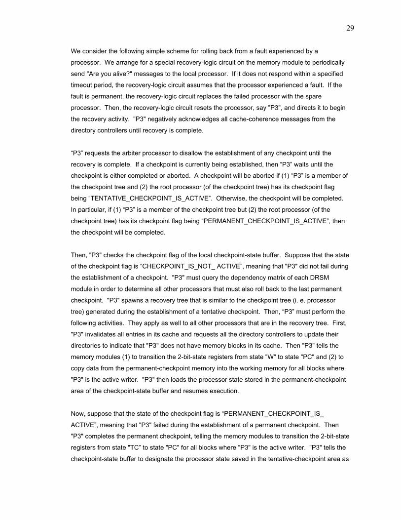
29
We consider the following simple scheme for rolling back from a fault experienced by a
processor. We arrange for a special recovery-logic circuit on the memory module to periodically
send "Are you alive?" messages to the local processor. If it does not respond within a specified
timeout period, the recovery-logic circuit assumes that the processor experienced a fault. If the
fault is permanent, the recovery-logic circuit replaces the failed processor with the spare
processor. Then, the recovery-logic circuit resets the processor, say "P3", and directs it to begin
the recovery activity. "P3" negatively acknowledges all cache-coherence messages from the
directory controllers until recovery is complete.
ÒP3Ó requests the arbiter processor to disallow the establishment of any checkpoint until the
recovery is complete. If a checkpoint is currently being established, then ÒP3Ó waits until the
checkpoint is either completed or aborted. A checkpoint will be aborted if (1) ÒP3Ó is a member of
the checkpoint tree and (2) the root processor (of the checkpoint tree) has its checkpoint flag
being ÒTENTATIVE_CHECKPOINT_IS_ACTIVEÓ. Otherwise, the checkpoint will be completed.
In particular, if (1) ÒP3Ó is a member of the checkpoint tree but (2) the root processor (of the
checkpoint tree) has its checkpoint flag being ÒPERMANENT_CHECKPOINT_IS_ACTIVEÓ, then
the checkpoint will be completed.
Then, "P3" checks the checkpoint flag of the local checkpoint-state buffer. Suppose that the state
of the checkpoint flag is ÒCHECKPOINT_IS_NOT_ ACTIVEÓ, meaning that "P3" did not fail during
the establishment of a checkpoint. "P3" must query the dependency matrix of each DRSM
module in order to determine all other processors that must also roll back to the last permanent
checkpoint. "P3" spawns a recovery tree that is similar to the checkpoint tree (i. e. processor
tree) generated during the establishment of a tentative checkpoint. Then, ÒP3Ó must perform the
following activities. They apply as well to all other processors that are in the recovery tree. First,
"P3" invalidates all entries in its cache and requests all the directory controllers to update their
directories to indicate that "P3" does not have memory blocks in its cache. Then "P3" tells the
memory modules (1) to transition the 2-bit-state registers from state "W" to state "PC" and (2) to
copy data from the permanent-checkpoint memory into the working memory for all blocks where
"P3" is the active writer. "P3" then loads the processor state stored in the permanent-checkpoint
area of the checkpoint-state buffer and resumes execution.
Now, suppose that the state of the checkpoint flag is ÒPERMANENT_CHECKPOINT_IS_
ACTIVEÓ, meaning that "P3" failed during the establishment of a permanent checkpoint. Then
"P3" completes the permanent checkpoint, telling the memory modules to transition the 2-bit-state
registers from state "TCÓ to state "PC" for all blocks where "P3" is the active writer. "P3" tells the
checkpoint-state buffer to designate the processor state saved in the tentative-checkpoint area as
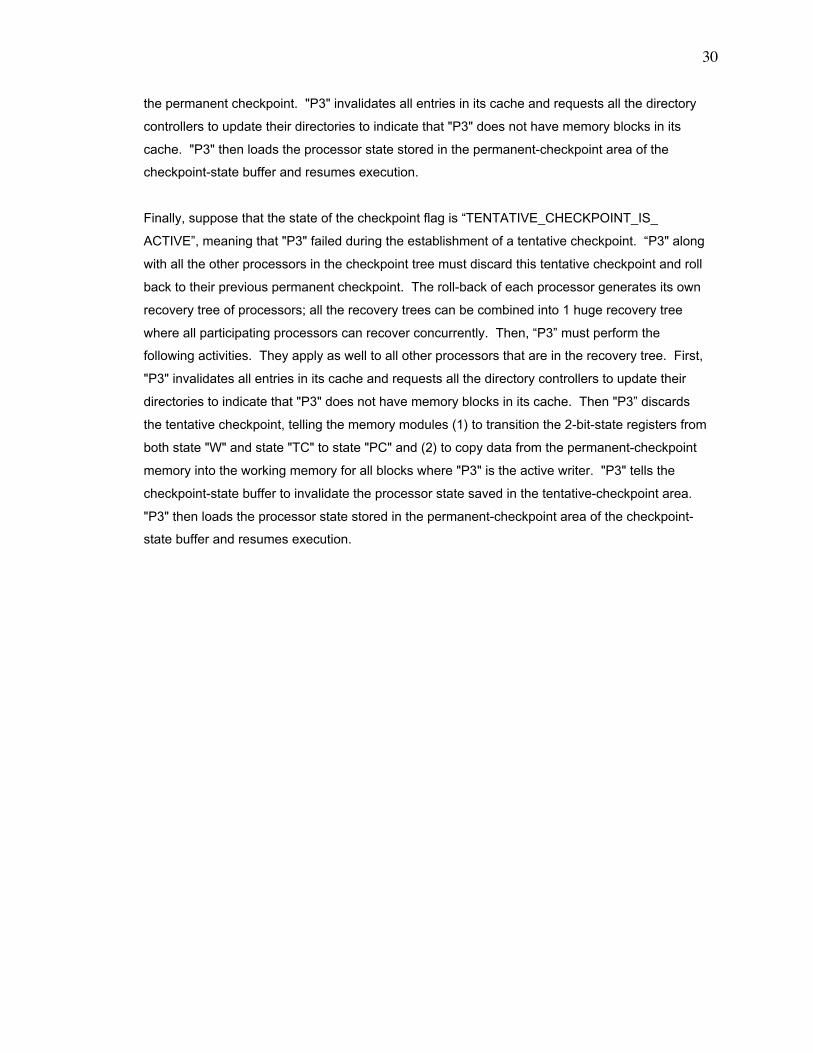
30
the permanent checkpoint. "P3" invalidates all entries in its cache and requests all the directory
controllers to update their directories to indicate that "P3" does not have memory blocks in its
cache. "P3" then loads the processor state stored in the permanent-checkpoint area of the
checkpoint-state buffer and resumes execution.
Finally, suppose that the state of the checkpoint flag is ÒTENTATIVE_CHECKPOINT_IS_
ACTIVEÓ, meaning that "P3" failed during the establishment of a tentative checkpoint. ÒP3" along
with all the other processors in the checkpoint tree must discard this tentative checkpoint and roll
back to their previous permanent checkpoint. The roll-back of each processor generates its own
recovery tree of processors; all the recovery trees can be combined into 1 huge recovery tree
where all participating processors can recover concurrently. Then, ÒP3Ó must perform the
following activities. They apply as well to all other processors that are in the recovery tree. First,
"P3" invalidates all entries in its cache and requests all the directory controllers to update their
directories to indicate that "P3" does not have memory blocks in its cache. Then "P3Ó discards
the tentative checkpoint, telling the memory modules (1) to transition the 2-bit-state registers from
both state "W" and state "TC" to state "PC" and (2) to copy data from the permanent-checkpoint
memory into the working memory for all blocks where "P3" is the active writer. "P3" tells the
checkpoint-state buffer to invalidate the processor state saved in the tentative-checkpoint area.
"P3" then loads the processor state stored in the permanent-checkpoint area of the checkpoint-
state buffer and resumes execution.
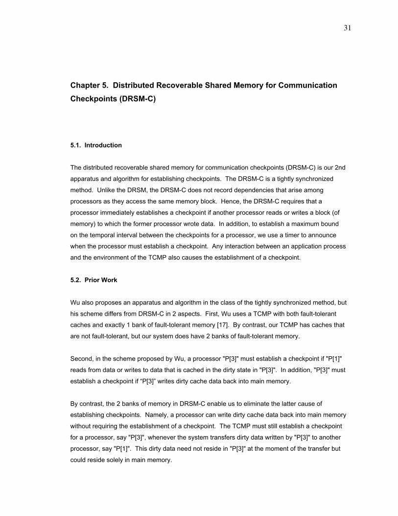
31
Chapter 5. Distributed Recoverable Shared Memory for Communication
Checkpoints (DRSM-C)
5.1. Introduction
The distributed recoverable shared memory for communication checkpoints (DRSM-C) is our 2nd
apparatus and algorithm for establishing checkpoints. The DRSM-C is a tightly synchronized
method. Unlike the DRSM, the DRSM-C does not record dependencies that arise among
processors as they access the same memory block. Hence, the DRSM-C requires that a
processor immediately establishes a checkpoint if another processor reads or writes a block (of
memory) to which the former processor wrote data. In addition, to establish a maximum bound
on the temporal interval between the checkpoints for a processor, we use a timer to announce
when the processor must establish a checkpoint. Any interaction between an application process
and the environment of the TCMP also causes the establishment of a checkpoint.
5.2. Prior Work
Wu also proposes an apparatus and algorithm in the class of the tightly synchronized method, but
his scheme differs from DRSM-C in 2 aspects. First, Wu uses a TCMP with both fault-tolerant
caches and exactly 1 bank of fault-tolerant memory [17]. By contrast, our TCMP has caches that
are not fault-tolerant, but our system does have 2 banks of fault-tolerant memory.
Second, in the scheme proposed by Wu, a processor "P[3]" must establish a checkpoint if "P[1]"
reads from data or writes to data that is cached in the dirty state in "P[3]". In addition, "P[3]" must
establish a checkpoint if ÒP[3]Ó writes dirty cache data back into main memory.
By contrast, the 2 banks of memory in DRSM-C enable us to eliminate the latter cause of
establishing checkpoints. Namely, a processor can write dirty cache data back into main memory
without requiring the establishment of a checkpoint. The TCMP must still establish a checkpoint
for a processor, say "P[3]", whenever the system transfers dirty data written by "P[3]" to another
processor, say "P[1]". This dirty data need not reside in "P[3]" at the moment of the transfer but
could reside solely in main memory.
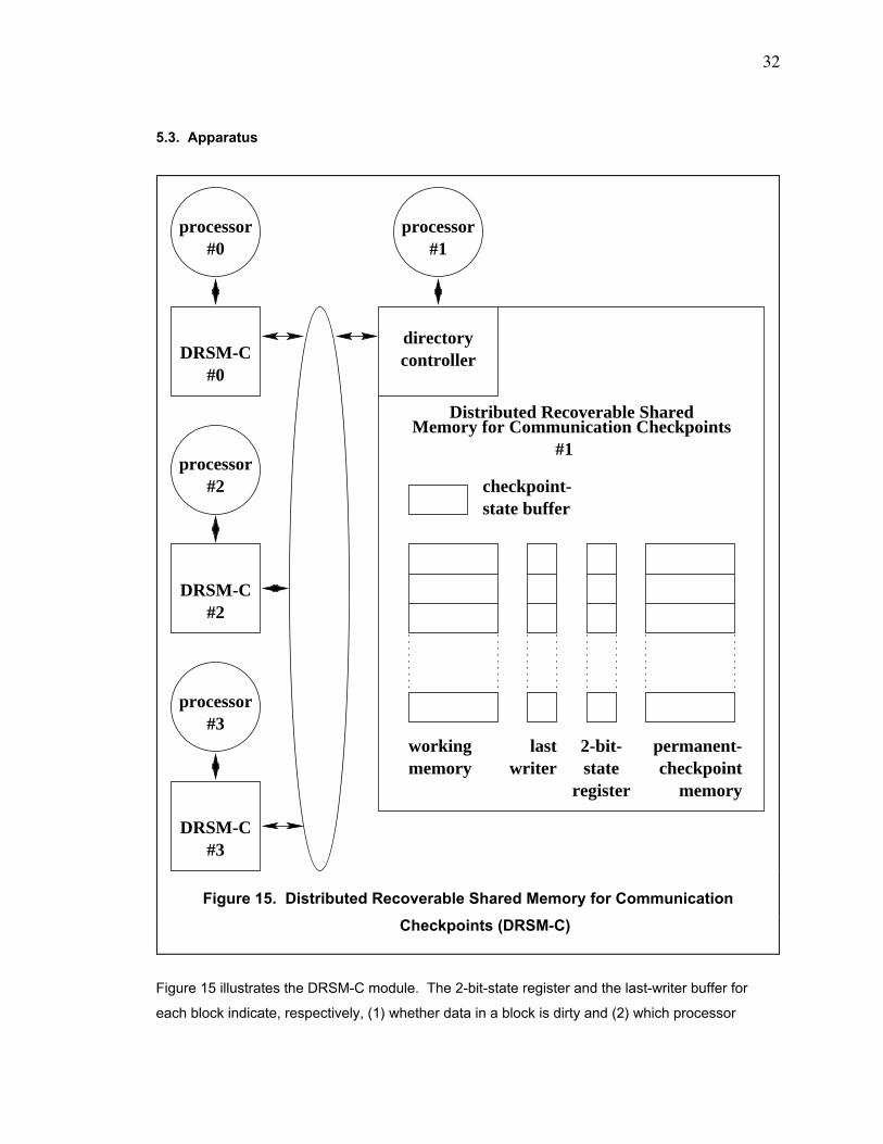
32
5.3. Apparatus
Figure 15 illustrates the DRSM-C module. The 2-bit-state register and the last-writer buffer for
each block indicate, respectively, (1) whether data in a block is dirty and (2) which processor
writer
directorycontroller
2-bit-state
register
processor#1
processor#0
DRSM-C
processor#2
DRSM-C
processor#3
DRSM-C#0
#2
#3
Distributed Recoverable Shared
#1
state buffer
Memory for Communication Checkpoints
checkpoint-
checkpointpermanent-
memory
workingmemory
last
Figure 15. Distributed Recoverable Shared Memory for Communication
Checkpoints (DRSM-C)
33
must establish a checkpoint in the event that the dirty data is transferred to another processor.
The DRSM-C module omits the dependency matrix. Any dependency that arises immediately
forces the establishment of a checkpoint; the newly established checkpoint erases the
dependency and hence obviates the need for a matrix to record the dependency.
When an access arrives at a DRSM-C module, it checks whether the matching block of memory
contains dirty data. If the block contains dirty data, the DRSM-C module sends a negative
acknowledgment to the memory-accessing processor and then requests that the last-writer
processor (of the block with dirty data) establishes a checkpoint. The 2-bit-state register and the
last-writer buffer provide sufficient information to determine whether to negatively acknowledge a
memory access.
5.4. Triggers of Checkpoint Establishment
Three events can trigger the establishment of a checkpoint.
5.5. Establishing Checkpoints
5.5.1. General Overview
Figure 16 illustrates the algorithm for establishing a checkpoint for a 4-processor TCMP. The
general strategy is that a processor wishing to establish a checkpoint simply does the following.
The processor writes its dirty cache data back into memory and requests that each DRSM-C
module establishes a tentative checkpoint for the blocks containing data written by the processor.
Once all the modules acknowledge completion of the tentative checkpoint, the processor
1. timer-triggered checkpoint: A timer expires. When the timer fora processor expires, it establishes a checkpoint. The timerensures a maximum bound on the time interval between checkpoints.
2. communication-triggered checkpoint: Dirty data is transferredbetween processors. Since the DRSM-C does not recorddependencies among processors and hence does not permit roll-backpropagation, any dependency that arises (like that caused bytransferring dirty data between processors) forces theestablishment of a checkpoint to erase the dependency.
3. external-communication-triggered checkpoint: Communicationoccurs between a processor and the environment outside of theTCMP. When data leaves or enters a TCMP, the processor handlingthe data must establish a checkpoint. Communication includesinterrupts.
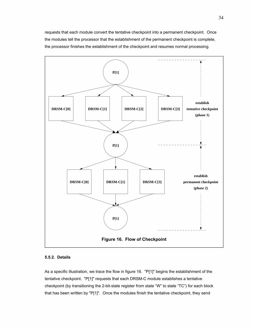
34
requests that each module convert the tentative checkpoint into a permanent checkpoint. Once
the modules tell the processor that the establishment of the permanent checkpoint is complete,
the processor finishes the establishment of the checkpoint and resumes normal processing.
5.5.2. Details
As a specific illustration, we trace the flow in figure 16. "P[1]" begins the establishment of the
tentative checkpoint. "P[1]" requests that each DRSM-C module establishes a tentative
checkpoint (by transitioning the 2-bit-state register from state ÒWÓ to state ÒTCÓ) for each block
that has been written by "P[1]". Once the modules finish the tentative checkpoint, they send
(phase 2)
P[1]
P[1]
DRSM-C[1]
P[1]
DRSM-C[0] DRSM-C[3]
DRSM-C[0] DRSM-C[1]
(phase 1)
tentative checkpoint
establish
DRSM-C[3]DRSM-C[2]
establish
permanent checkpoint
Figure 16. Flow of Checkpoint
35
acknowledgments to "P[1]". It then begins the 2nd phase, which is establishing the permanent
checkpoint. "P[1]" then requests that each DRSM-C module except "DRSM-C[2]" transitions the
2-bit-state register of each block from state ÒTCÓ to state ÒPCÓ. In our example, "DRSM-C[2]"
does not contain any blocks to which "P[1]" has written data since the last checkpoint of ÒP[1]Ó, so
"DRSM-C[2]" does not transition the 2-bit-state register of any block into state ÒTCÓ and hence
does not participate in the permanent-checkpoint phase. After all 3 DRSM-C modules complete
the permanent checkpoint, they send acknowledgments to "P[1]". It then resumes normal
processing.
Figure 16 shows the general flow in establishing a tentative checkpoint but omits 3 important
details. They are the following.
Also, we should note the following. "P[1]" sets the checkpoint flag to "PERMANENT_
CHECKPOINT_IS_ACTIVE" just before "P[1]" begins the phase for the establishment of the
permanent checkpoint. After its establishment is complete, "P[1]" sets the checkpoint flag to
"CHECKPOINT_IS_NOT_ACTIVE". Finally, each processor tells its local memory module to
designate the tentative checkpoint of the processor state in the checkpoint-state buffer as a
permanent checkpoint.
5.6. Recovery from a Fault
We consider the following simple scheme for rolling back from a fault experienced by a
processor. We arrange for a special recovery-logic circuit on the memory module to periodically
send "Are you alive?" messages to the local processor. If it does not respond within a specified
1. Before a processor requests all DRSM-C modules to transition blocks into the tentative-checkpoint state, the processor (1) waits until all its pending cache operations are finishedor negatively acknowledged and (2) then writes all dirty cache data back into memory. Theprocessor waits for the DRSM-C modules to acknowledge that all the write-backs arecomplete.
2. Each processor sends a copy of its state (i. e. data in the internal registers) to thecheckpoint-state buffer of the DRSM-C module that is local to the processor.
3. Just before the processor begins the establishment of the tentative checkpoint, thatprocessor sets a 2-bit checkpoint flag in the checkpoint-state buffer of the local memorymodule to indicate that the establishment of the tentative checkpoint is active. The state ofthe checkpoint flag can be 1 of {CHECKPOINT_IS_NOT_ACTIVE, TENTATIVE_CHECKPOINT_IS_ACTIVE, PERMANENT_CHECKPOINT_IS_ACTIVE}. In figure 16,processor "P[1]" sets the checkpoint flag to "TENTATIVE_CHECKPOINT_IS_ACTIVE".The TCMP uses this state information to determine what to do in the event that a faultoccurs during the establishment of a checkpoint.
36
timeout period, the recovery-logic circuit assumes that the processor experienced a fault. If the
fault is permanent, the recovery-logic circuit replaces the failed processor with the spare
processor. Then, the recovery-logic circuit resets the processor, say "P3", and directs it to begin
the recovery activity. "P3" negatively acknowledges all cache-coherence messages from the
directory controllers until recovery is complete. "P3" invalidates all entries in its cache and
requests all the directory controllers to update their directories to indicate that "P3" does not have
memory blocks in its cache.
"P3" checks the checkpoint flag of the local checkpoint-state buffer. Suppose that the state of the
checkpoint flag is ÒCHECKPOINT_IS_NOT_ ACTIVEÓ, meaning that "P3" did not fail during the
establishment of a checkpoint. Then "P3" tells the memory modules (1) to transition the 2-bit-
state registers from state "W" to state "PC" and (2) to copy data from the permanent-checkpoint
memory into the working memory for all blocks where "P3" is the active writer. "P3" then loads
the processor state stored in the permanent-checkpoint area of the checkpoint-state buffer and
resumes execution.
Suppose that the state of the checkpoint flag is ÒPERMANENT_CHECKPOINT_IS_ACTIVEÓ,
meaning that "P3" failed during the establishment of a permanent checkpoint. Then "P3"
completes the permanent checkpoint, telling the memory modules to transition the 2-bit-state
registers from state "TCÓ to state "PC" for all blocks where "P3" is the active writer. "P3" tells the
checkpoint-state buffer to designate the processor state saved in the tentative-checkpoint area as
the permanent checkpoint. "P3" invalidates all entries in its cache and requests all the directory
controllers to update their directories to indicate that "P3" does not have memory blocks in its
cache. "P3" then loads the processor state stored in the permanent-checkpoint area of the
checkpoint-state buffer and resumes execution.
Finally, suppose that the state of the checkpoint flag is ÒTENTATIVE_CHECKPOINT_IS_
ACTIVEÓ, meaning that "P3" failed during the establishment of a tentative checkpoint. Then "P3"
discards the tentative checkpoint, telling the memory modules (1) to transition the 2-bit-state
registers from both state "W" and state "TC" to state "PC" and (2) to copy data from the
permanent-checkpoint memory into the working memory for all blocks where "P3" is the active
writer. "P3" tells the checkpoint-state buffer to invalidate the processor state saved in the
tentative-checkpoint area. "P3" invalidates all entries in its cache and requests all the directory
controllers to update their directories to indicate that "P3" does not have memory blocks in its
cache. "P3" then loads the processor state stored in the permanent-checkpoint area of the
checkpoint-state buffer and resumes execution.
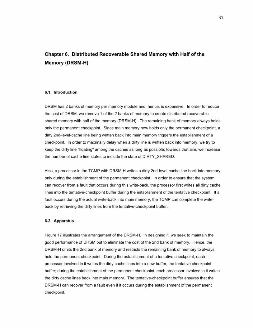
37
Chapter 6. Distributed Recoverable Shared Memory with Half of the
Memory (DRSM-H)
6.1. Introduction
DRSM has 2 banks of memory per memory module and, hence, is expensive. In order to reduce
the cost of DRSM, we remove 1 of the 2 banks of memory to create distributed recoverable
shared memory with half of the memory (DRSM-H). The remaining bank of memory always holds
only the permanent checkpoint. Since main memory now holds only the permanent checkpoint, a
dirty 2nd-level-cache line being written back into main memory triggers the establishment of a
checkpoint. In order to maximally delay when a dirty line is written back into memory, we try to
keep the dirty line "floating" among the caches as long as possible; towards that aim, we increase
the number of cache-line states to include the state of DIRTY_SHARED.
Also, a processor in the TCMP with DRSM-H writes a dirty 2nd-level-cache line back into memory
only during the establishment of the permanent checkpoint. In order to ensure that the system
can recover from a fault that occurs during this write-back, the processor first writes all dirty cache
lines into the tentative-checkpoint buffer during the establishment of the tentative checkpoint. If a
fault occurs during the actual write-back into main memory, the TCMP can complete the write-
back by retrieving the dirty lines from the tentative-checkpoint buffer.
6.2. Apparatus
Figure 17 illustrates the arrangement of the DRSM-H. In designing it, we seek to maintain the
good performance of DRSM but to eliminate the cost of the 2nd bank of memory. Hence, the
DRSM-H omits the 2nd bank of memory and restricts the remaining bank of memory to always
hold the permanent checkpoint. During the establishment of a tentative checkpoint, each
processor involved in it writes the dirty cache lines into a new buffer, the tentative checkpoint
buffer; during the establishment of the permanent checkpoint, each processor involved in it writes
the dirty cache lines back into main memory. The tentative-checkpoint buffer ensures that the
DRSM-H can recover from a fault even if it occurs during the establishment of the permanent
checkpoint.
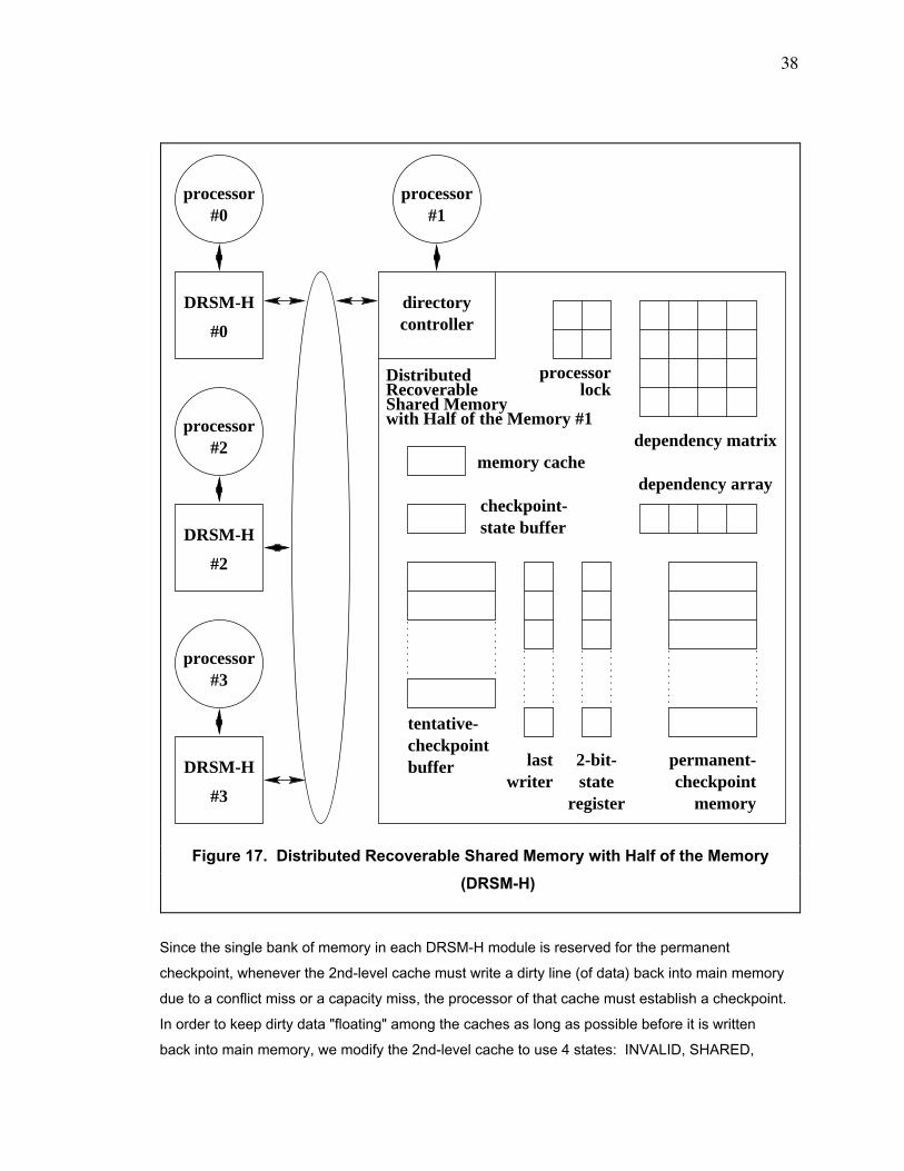
38
Since the single bank of memory in each DRSM-H module is reserved for the permanent
checkpoint, whenever the 2nd-level cache must write a dirty line (of data) back into main memory
due to a conflict miss or a capacity miss, the processor of that cache must establish a checkpoint.
In order to keep dirty data "floating" among the caches as long as possible before it is written
back into main memory, we modify the 2nd-level cache to use 4 states: INVALID, SHARED,
writer
directorycontroller
processor#1
processor#0
processor#2
processor#3
DRSM-H
#2
DRSM-H
#3
DRSM-H
#0
2-bit-state
register
memory cache
DistributedRecoverableShared Memorywith Half of the Memory #1
processor
dependency matrix
dependency array
state buffercheckpoint-
lock
tentative-checkpointbuffer permanent-
checkpointmemory
last
Figure 17. Distributed Recoverable Shared Memory with Half of the Memory
(DRSM-H)
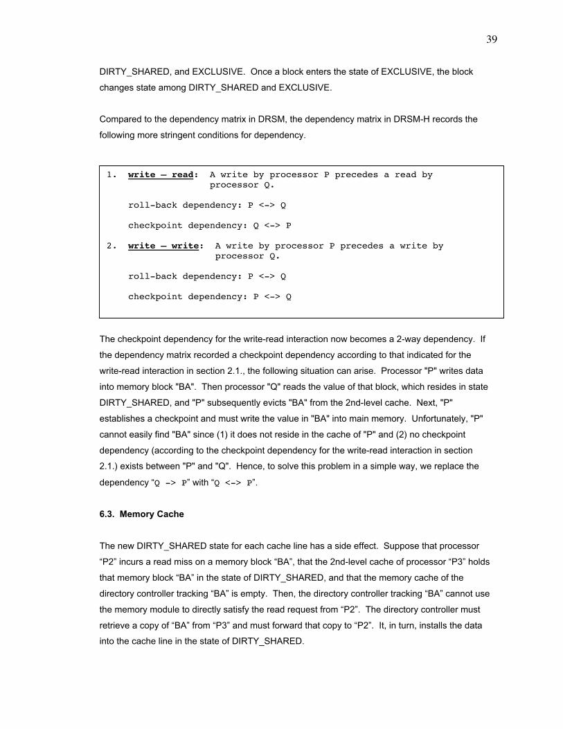
39
DIRTY_SHARED, and EXCLUSIVE. Once a block enters the state of EXCLUSIVE, the block
changes state among DIRTY_SHARED and EXCLUSIVE.
Compared to the dependency matrix in DRSM, the dependency matrix in DRSM-H records the
following more stringent conditions for dependency.
The checkpoint dependency for the write-read interaction now becomes a 2-way dependency. If
the dependency matrix recorded a checkpoint dependency according to that indicated for the
write-read interaction in section 2.1., the following situation can arise. Processor "P" writes data
into memory block "BA". Then processor "Q" reads the value of that block, which resides in state
DIRTY_SHARED, and "P" subsequently evicts "BA" from the 2nd-level cache. Next, "P"
establishes a checkpoint and must write the value in "BA" into main memory. Unfortunately, "P"
cannot easily find "BA" since (1) it does not reside in the cache of "P" and (2) no checkpoint
dependency (according to the checkpoint dependency for the write-read interaction in section
2.1.) exists between "P" and "Q". Hence, to solve this problem in a simple way, we replace the
dependency ÒQ -> PÓ with ÒQ <-> PÓ.
6.3. Memory Cache
The new DIRTY_SHARED state for each cache line has a side effect. Suppose that processor
ÒP2Ó incurs a read miss on a memory block ÒBAÓ, that the 2nd-level cache of processor ÒP3Ó holds
that memory block ÒBAÓ in the state of DIRTY_SHARED, and that the memory cache of the
directory controller tracking ÒBAÓ is empty. Then, the directory controller tracking ÒBAÓ cannot use
the memory module to directly satisfy the read request from ÒP2Ó. The directory controller must
retrieve a copy of ÒBAÓ from ÒP3Ó and must forward that copy to ÒP2Ó. It, in turn, installs the data
into the cache line in the state of DIRTY_SHARED.
1. write Ð read: A write by processor P precedes a read by processor Q.
roll-back dependency: P <-> Q
checkpoint dependency: Q <-> P
2. write Ð write: A write by processor P precedes a write by processor Q.
roll-back dependency: P <-> Q
checkpoint dependency: P <-> Q
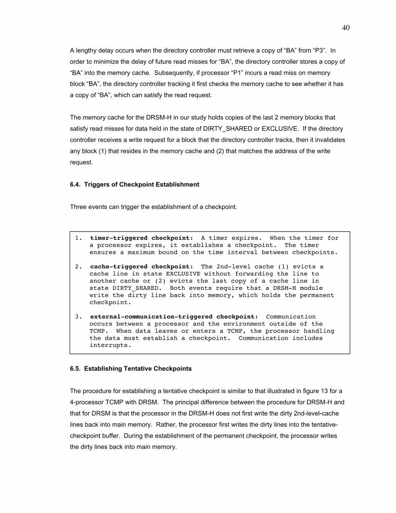
40
A lengthy delay occurs when the directory controller must retrieve a copy of ÒBAÓ from ÒP3Ó. In
order to minimize the delay of future read misses for ÒBAÓ, the directory controller stores a copy of
ÒBAÓ into the memory cache. Subsequently, if processor ÒP1Ó incurs a read miss on memory
block ÒBAÓ, the directory controller tracking it first checks the memory cache to see whether it has
a copy of ÒBAÓ, which can satisfy the read request.
The memory cache for the DRSM-H in our study holds copies of the last 2 memory blocks that
satisfy read misses for data held in the state of DIRTY_SHARED or EXCLUSIVE. If the directory
controller receives a write request for a block that the directory controller tracks, then it invalidates
any block (1) that resides in the memory cache and (2) that matches the address of the write
request.
6.4. Triggers of Checkpoint Establishment
Three events can trigger the establishment of a checkpoint.
6.5. Establishing Tentative Checkpoints
The procedure for establishing a tentative checkpoint is similar to that illustrated in figure 13 for a
4-processor TCMP with DRSM. The principal difference between the procedure for DRSM-H and
that for DRSM is that the processor in the DRSM-H does not first write the dirty 2nd-level-cache
lines back into main memory. Rather, the processor first writes the dirty lines into the tentative-
checkpoint buffer. During the establishment of the permanent checkpoint, the processor writes
the dirty lines back into main memory.
1. timer-triggered checkpoint: A timer expires. When the timer fora processor expires, it establishes a checkpoint. The timerensures a maximum bound on the time interval between checkpoints.
2. cache-triggered checkpoint: The 2nd-level cache (1) evicts acache line in state EXCLUSIVE without forwarding the line toanother cache or (2) evicts the last copy of a cache line instate DIRTY_SHARED. Both events require that a DRSM-H modulewrite the dirty line back into memory, which holds the permanentcheckpoint.
3. external-communication-triggered checkpoint: Communicationoccurs between a processor and the environment outside of theTCMP. When data leaves or enters a TCMP, the processor handlingthe data must establish a checkpoint. Communication includesinterrupts.
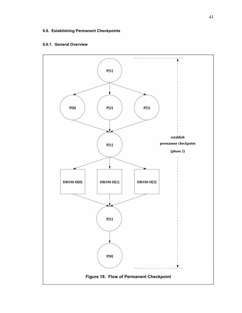
41
6.6. Establishing Permanent Checkpoints
6.6.1. General Overview
(phase 2)
P[1]
P[2]P[0] P[3]
P[1]
DRSM-H[1]
P[1]
P[0]
DRSM-H[0] DRSM-H[3]
establish
permanent checkpoint
Figure 18. Flow of Permanent Checkpoint
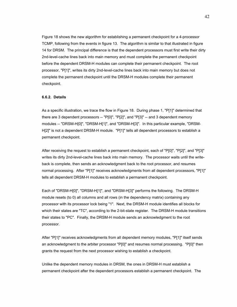
42
Figure 18 shows the new algorithm for establishing a permanent checkpoint for a 4-processor
TCMP, following from the events in figure 13. The algorithm is similar to that illustrated in figure
14 for DRSM. The principal difference is that the dependent processors must first write their dirty
2nd-level-cache lines back into main memory and must complete the permanent checkpoint
before the dependent DRSM-H modules can complete their permanent checkpoint. The root
processor, "P[1]", writes its dirty 2nd-level-cache lines back into main memory but does not
complete the permanent checkpoint until the DRSM-H modules complete their permanent
checkpoint.
6.6.2. Details
As a specific illustration, we trace the flow in Figure 18. During phase 1, "P[1]" determined that
there are 3 dependent processors -- "P[0]", "P[2]", and "P[3]" -- and 3 dependent memory
modules -- "DRSM-H[0]", "DRSM-H[1]", and "DRSM-H[3]". In this particular example, "DRSM-
H[2]" is not a dependent DRSM-H module. "P[1]" tells all dependent processors to establish a
permanent checkpoint.
After receiving the request to establish a permanent checkpoint, each of "P[0]", "P[2]", and "P[3]"
writes its dirty 2nd-level-cache lines back into main memory. The processor waits until the write-
back is complete, then sends an acknowledgment back to the root processor, and resumes
normal processing. After "P[1]" receives acknowledgments from all dependent processors, "P[1]"
tells all dependent DRSM-H modules to establish a permanent checkpoint.
Each of "DRSM-H[0]", "DRSM-H[1]", and "DRSM-H[3]" performs the following. The DRSM-H
module resets (to 0) all columns and all rows (in the dependency matrix) containing any
processor with its processor lock being "1". Next, the DRSM-H module identifies all blocks for
which their states are "TC", according to the 2-bit-state register. The DRSM-H module transitions
their states to "PC". Finally, the DRSM-H module sends an acknowledgment to the root
processor.
After "P[1]" receives acknowledgments from all dependent memory modules, "P[1]" itself sends
an acknowledgment to the arbiter processor "P[0]" and resumes normal processing. "P[0]" then
grants the request from the next processor wishing to establish a checkpoint.
Unlike the dependent memory modules in DRSM, the ones in DRSM-H must establish a
permanent checkpoint after the dependent processors establish a permanent checkpoint. The

43
dependent processors must write the dirty lines in their caches back into main memory (which
contains the permanent checkpoint) during the establishment of the permanent checkpoint. Only
after this activity is complete can the dependent memory modules convert their tentative
checkpoint into a permanent one.
Concerning figure 18, we note the following additional details for DRSM-H. At the start of phase
2, ÒP[1]Ó updates the checkpoint flag of the checkpoint-state buffer to ÒTENTATIVE_
CHECKPOINT_IS_ACTIVEÓ. During phase 2, the dependent processors write all the dirty lines in
their 2nd-level caches back into main memory. A safe copy of these blocks exists in the
tentative-checkpoint buffer, so if a fault occurs during the write-back, the TCMP can still recover
from the fault. Further, each dependent processor directs the checkpoint-state buffer to invalidate
its old permanent checkpoint and to designate the processor state saved in the tentative-
checkpoint area as the new permanent checkpoint. Each dependent memory module clears, in
the dependency matrix, all rows and columns containing any processor with its processor lock
being "1" and then resets all the processor locks to "0". At the end of phase 2, "P[1]" directs the
checkpoint-state buffer to invalidate its old permanent checkpoint and to designate the processor
state saved in the tentative-checkpoint area as the new permanent checkpoint, and "P[1]" then
updates the checkpoint flag of the checkpoint-state buffer to ÒCHECKPOINT_IS_NOT_ACTIVEÓ,
indicating that phase 2 (and the entire checkpoint) is complete.
6.7. Recovery from a Fault
The recovery procedure for DRSM-H is similar to that for DRSM. The principal difference is that if
"P3" failed during the establishment of a permanent checkpoint, then "P3" must read the
associated tentative-checkpoint buffer and must write all dirty blocks back into main memory in
order to complete the permanent checkpoint during recovery.
44
Chapter 7. Distributed Recoverable Shared Memory with Logs (DRSM-L)
7.1. Introduction
Distributed recoverable shared memory with logs (DRSM-L) is an apparatus and algorithm in the
class of the unsynchronized method to establish checkpoints. DRSM-L enables a processor to
establish a checkpoint (or to roll back to the last checkpoint) in a manner that is independent of
any other processor.
DRSM-L differs fundamentally from DRSM, DRSM-C, and DRSM-H in that a processor can
establish a checkpoint independently of all other processors. A processor in the TCMP with
DRSM-L has this flexibility since the processor ensures that dirty data sent to other processors is
never lost even if the sending processor rolls back to the previous checkpoint. Specifically, each
processor logs each incoming cache line into the line buffer of the local DRSM-L module and logs
the number of accesses (that the processor makes) to this cache line into the counter buffer of
the DRSM-L module. If the processor encounters a fault and rolls back to the last checkpoint, the
processor uses the cache data and access history recorded in the line buffer and the counter
buffer to satisfy all cache accesses during the recovery period. Once the recovery completes, the
processor resumes normal execution. The processor re-calculates exactly the original values of
the dirty data that the processor sent to other processors prior to encountering the fault. We note
that DRSM-L also enables a processor to roll back to the last checkpoint independently of all
other processors.
7.2. Apparatus
Figure 19 illustrates the apparatus of DRSM-L. It consists of new structures in both the 2nd-level
cache and the local memory module. Each line of the 2nd-level cache has the traditional fields:
tag, status (SHARED, EXCLUSIVE, and INVALID) of line, and line of data. Each line has 3
additional fields: counter, instruction/data flag, and 2-bit status flag. The 2-bit-status flag
assumes any 1 of 4 values: ÒNÓ (no event), ÒRÓ (remote read), ÒEÓ (ejection), ÒVÓ (counter
overflow). The cache also has 2 index registers that mirror 2 index registers in the local memory
module.
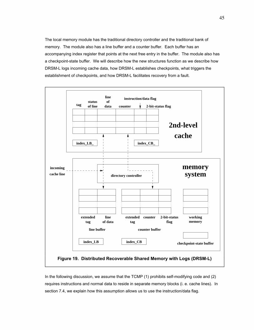
45
The local memory module has the traditional directory controller and the traditional bank of
memory. The module also has a line buffer and a counter buffer. Each buffer has an
accompanying index register that points at the next free entry in the buffer. The module also has
a checkpoint-state buffer. We will describe how the new structures function as we describe how
DRSM-L logs incoming cache data, how DRSM-L establishes checkpoints, what triggers the
establishment of checkpoints, and how DRSM-L facilitates recovery from a fault.
In the following discussion, we assume that the TCMP (1) prohibits self-modifying code and (2)
requires instructions and normal data to reside in separate memory blocks (i. e. cache lines). In
section 7.4, we explain how this assumption allows us to use the instruction/data flag.
flag memoryworkingextendedextended line
index_CBindex_LB
tagstatusof line data
ofline
counter
index_LB_ index_CB_
2nd-levelcache
systemmemory
directory controllercache line
incoming
line buffer counter buffer
of datatag tag2-bit-statuscounter
checkpoint-state buffer
instruction/data flag
2-bit-status flag
Figure 19. Distributed Recoverable Shared Memory with Logs (DRSM-L)
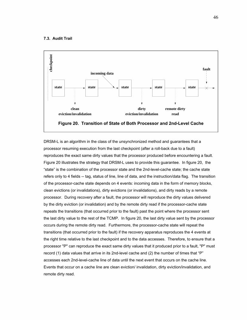
46
7.3. Audit Trail
DRSM-L is an algorithm in the class of the unsynchronized method and guarantees that a
processor resuming execution from the last checkpoint (after a roll-back due to a fault)
reproduces the exact same dirty values that the processor produced before encountering a fault.
Figure 20 illustrates the strategy that DRSM-L uses to provide this guarantee. In figure 20, the
ÒstateÓ is the combination of the processor state and the 2nd-level-cache state; the cache state
refers only to 4 fields -- tag, status of line, line of data, and the instruction/data flag. The transition
of the processor-cache state depends on 4 events: incoming data in the form of memory blocks,
clean evictions (or invalidations), dirty evictions (or invalidations), and dirty reads by a remote
processor. During recovery after a fault, the processor will reproduce the dirty values delivered
by the dirty eviction (or invalidation) and by the remote dirty read if the processor-cache state
repeats the transitions (that occurred prior to the fault) past the point where the processor sent
the last dirty value to the rest of the TCMP. In figure 20, the last dirty value sent by the processor
occurs during the remote dirty read. Furthermore, the processor-cache state will repeat the
transitions (that occurred prior to the fault) if the recovery apparatus reproduces the 4 events at
the right time relative to the last checkpoint and to the data accesses. Therefore, to ensure that a
processor "P" can reproduce the exact same dirty values that it produced prior to a fault, "P" must
record (1) data values that arrive in its 2nd-level cache and (2) the number of times that ÒPÓ
accesses each 2nd-level-cache line of data until the next event that occurs on the cache line.
Events that occur on a cache line are clean eviction/ invalidation, dirty eviction/invalidation, and
remote dirty read.
remote dirty
state
chec
kpoi
nt
state
incoming data
state state state
eviction/invalidationdirtyclean
eviction/invalidation
fault
read
Figure 20. Transition of State of Both Processor and 2nd-Level Cache

47
"P" logs the incoming cache lines (or memory blocks) into the line buffer in figure 19. The line
buffer has 2 fields: extended tag and line of data. The extended tag is the regular 2nd-level-
cache tag appended with the index of the exact cache line into which the incoming cache data is
destined. The "line of data" is the cache data itself. The logging of the incoming cache line into
the line buffer can be performed in parallel with forwarding the line to the 2nd-level cache, so the
logging does not cause additional delay.
Merely recording the incoming cache line is not sufficient to guarantee that "P" will reproduce the
exact same dirty values that it produced prior to a fault. "P" must also record the number of times
that ÒPÓ uses data in a 2nd-level-cache line before an event occurs on it. Below are the 3
possible events.
To count the number of accesses to data in a 2nd-level cache prior to these events, "P" performs
the following. "P" forwards the address of the access to both the 1st-level cache and the 2nd-
level cache. Regardless of whether the access hits in the 1st-level cache, if the access hits in a
line of the 2nd-level cache, it increments the counter of the matching line. The counter of a line is
reset to 0 whenever incoming cache data arrives in the line.
If a valid 2nd-level-cache line experiences any 1 of the above 3 events, then the cache writes the
counter of that cache line into the counter buffer in figure 19 and resets the counter (in the cache
line) to 0. The counter buffer has 3 fields: extended tag, counter, and 2-bit status flag. The
directory controller sets the 2-bit-status flag to ÒRÓ, ÒEÓ, or ÒVÓ if event #1, #2, or #3, respectively,
occurs. For events #1 and #2, logging the counter into the counter buffer is performed in parallel
with the usual cache-coherence activity, so the logging does not cause additional delay.
The line buffer and the counter buffer effectively record an audit trail of data accessed by a
processor "P". After "P" encounters a fault, "P" rolls back to the last checkpoint and resumes
execution. "P" uses the audit trail to satisfy all read or write misses until recovery is complete.
The information stored in the line buffer and the counter buffer is sufficient and necessary to
ensure that "P" will reproduce the exact same dirty values that it produced prior to a fault. We
illustrate how recovery works in section 7.7.
1. The status of the line transitions from EXCLUSIVE to SHARED dueto a read by a remote processor.
2. The status of the line transitions from SHARED or EXCLUSIVE toINVALID due to an eviction or invalidation.
3. The counter overflows.

48
If an upgrade miss (i. e. a write ÒhitÓ on a 2nd-level-cache line with its status being SHARED)
occurs in the 2nd-level cache, it obtains permission to upgrade the affected cache line in the
same way that the 2nd-level cache of a base TCMP without DRSM-L would handle the upgrade
miss. Upgrading a 2nd-level-cache line involves changing its status from SHARED to
EXCLUSIVE. After the 2nd-level cache upgrades the affected cache line, the cache retries the
data-write. The cache then processes the write hit in the usual fashion for maintaining an audit
trail.
7.4. Optimizations
For the 2nd-level cache, figure 19 shows 2 optimizations: the instruction/data flag and the index
registers which mirror those in the local memory module. If the TCMP both (1) prohibits self-
modifying code and (2) requires instructions and normal data to reside in separate memory
blocks (i. e. cache lines), then we can distinguish between cache lines holding instructions and
cache lines holding data. If the incoming cache line satisfies an access miss for regular data,
then the 2nd-level cache sets the instruction/data flag of the cache line (satisfying the access
miss) to 1. The incoming cache line and its associated counter are handled in the usual manner
for maintaining an audit trail. On the other hand, if the incoming cache line satisfies an instruction
miss, then the cache line is not saved in the line buffer. Further, the 2nd-level cache sets the
instruction/data flag of the cache line (satisfying the instruction miss) to 0. Subsequent instruction
fetches that hit in the cache line do not cause the counter to increment. In this way, we avoid
using space in the line buffer and the counter buffer to store the instructions and the number of
instruction fetches, respectively.
If the TCMP either (1) allows self-modifying code or (2) allows instructions and normal data to
reside in the same memory block (i. e. cache line), then we cannot distinguish between cache
lines holding instructions and cache lines holding data. We omit the instruction/data flag and
must handle all incoming cache lines in the usual manner for maintaining an audit trail.
The second optimization is the index registers that mirror those in the local memory module. In
the memory module, the index register of each buffer points to the next free entry in the buffer.
Òindex_LBÓ is the index register of the line buffer, and Òindex_CBÓ is the index register of the
counter buffer. Òindex_LB_Ó and Òindex_CB_Ó mirror Òindex_LBÓ and Òindex_CBÓ, respectively.
When the directory controller saves an incoming cache line (for a data access) into the line buffer
and forwards the line to the 2nd-level cache, the directory controller increments Òindex_LBÓ. The
2nd-level cache installs the incoming cache data into a cache line and increments Òindex_LB_Ó.
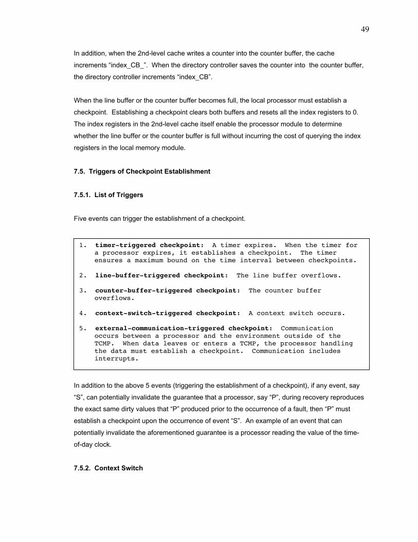
49
In addition, when the 2nd-level cache writes a counter into the counter buffer, the cache
increments Òindex_CB_Ó. When the directory controller saves the counter into the counter buffer,
the directory controller increments Òindex_CBÓ.
When the line buffer or the counter buffer becomes full, the local processor must establish a
checkpoint. Establishing a checkpoint clears both buffers and resets all the index registers to 0.
The index registers in the 2nd-level cache itself enable the processor module to determine
whether the line buffer or the counter buffer is full without incurring the cost of querying the index
registers in the local memory module.
7.5. Triggers of Checkpoint Establishment
7.5.1. List of Triggers
Five events can trigger the establishment of a checkpoint.
In addition to the above 5 events (triggering the establishment of a checkpoint), if any event, say
ÒSÓ, can potentially invalidate the guarantee that a processor, say ÒPÓ, during recovery reproduces
the exact same dirty values that ÒPÓ produced prior to the occurrence of a fault, then ÒPÓ must
establish a checkpoint upon the occurrence of event ÒSÓ. An example of an event that can
potentially invalidate the aforementioned guarantee is a processor reading the value of the time-
of-day clock.
7.5.2. Context Switch
1. timer-triggered checkpoint: A timer expires. When the timer fora processor expires, it establishes a checkpoint. The timerensures a maximum bound on the time interval between checkpoints.
2. line-buffer-triggered checkpoint: The line buffer overflows.
3. counter-buffer-triggered checkpoint: The counter bufferoverflows.
4. context-switch-triggered checkpoint: A context switch occurs.
5. external-communication-triggered checkpoint: Communicationoccurs between a processor and the environment outside of theTCMP. When data leaves or enters a TCMP, the processor handlingthe data must establish a checkpoint. Communication includesinterrupts.

50
The description of DRSM-L thus far applies to a single thread of a single process running on a
processor in a TCMP. In order to deal with multiple threads and processes, the DRSM-L must
direct a processor, ÒPÓ, to establish a checkpoint just after ÒPÓ switches context (and before ÒPÓ
sends any dirty data to the rest of the TCMP).
Establishing a checkpoint at each context switch will not cause appreciable deterioration in
performance. Establishing a checkpoint involves mainly saving the 2nd-level-cache and the
processor state into the checkpoint-state buffer and costs about 41 microseconds for a 8192-line
2nd-level cache of a 200 megahertz processor. The fastest context-switch time (of a thread) is
approximately 8 microseconds, scaled for a 200 megahertz SPARC processor from the results by
Narlikar [8]. The checkpoint time and the context-switch time have roughly the same order of
magnitude.
In calculating the checkpoint time of 41 microseconds, we use the parameters listed in section
8.1. The 2nd-level cache expends 75 cycles to grab the bus between the cache and the directory
controller. The 2nd-level cache then sends 1 cache line per cycle (in a pipelined fashion) to the
directory controller, which saves the line into the checkpoint-state buffer; transferring all 8192
2nd-level-cache lines requires 8192 cycles. Also, transferring the processor state to the directory
controller uses another 16 cycles. Hence, establishing a checkpoint requires 8283 cycles, which
is approximately 41 microseconds.
7.6. Establishing Checkpoints
The checkpoint-state buffer assists the local processor to establish a checkpoint. The
checkpoint-state buffer has 3 separate units (which are not shown in figure 19): the 2-bit
checkpoint flag, the tentative-checkpoint area, and the permanent-checkpoint area. The
checkpoint flag indicates 1 of 3 checkpointing states: "CHECKPOINT_IS_NOT_ACTIVE",
"TENTATIVE_CHECKPOINT_IS_ACTIVE", and "PERMANENT_CHECKPOINT_IS_ACTIVE".
The tentative-checkpoint area holds both (1) the processor state (of the local processor) and (2)
the contents of the 2nd-level cache for the current checkpoint. The permanent-checkpoint area
holds both (1) the processor state and (2) the contents of the 2nd-level cache from the last
checkpoint. At the end of the establishment of the current checkpoint, the local processor
switches the designation of the tentative-checkpoint area and the permanent-checkpoint area. In
other words, the tentative-checkpoint area becomes the permanent-checkpoint area, and the
permanent-checkpoint area becomes the tentative-checkpoint area.

51
DRSM-L enables a processor "P" to establish a checkpoint in 2 phases: tentative checkpoint and
permanent checkpoint. "P" first updates the checkpoint flag of the checkpoint-state buffer to
"TENTATIVE_CHECKPOINT_IS_ACTIVE", indicating that "P" is in phase 1, the tentative
checkpoint. Then, "P" waits until all its pending memory accesses are completed (or negatively
acknowledged). "P" negatively acknowledges all cache-coherence messages from the directory
controllers until the establishment of the checkpoint is complete. Next, "P" downloads both its
internal registers (i. e. the processor state) and all 2nd-level-cache lines (saving only the tag,
status of line, line of data, and instruction/data flag) into the tentative-checkpoint area of the
checkpoint-state buffer (while preserving the previous permanent checkpoint in the permanent-
checkpoint area). At the end of phase 1, "P" updates the checkpoint flag of the checkpoint-state
buffer to "PERMANENT_CHECKPOINT_IS_ACTIVE", indicating that "P" is now in phase 2 (i. e.
the permanent checkpoint). "P" resets all the index registers in both the processor module and
the local memory module. "P" then tells the checkpoint-state buffer to invalidate the old
permanent checkpoint in the checkpoint-state buffer and to designate the processor state and the
cache lines saved in the tentative-checkpoint area as the new permanent checkpoint. Finally, "P"
updates the checkpoint flag of the checkpoint-state buffer to "CHECKPOINT_IS_NOT_ACTIVE",
indicating that phase 2 (and the entire checkpoint) is finished.
7.7. Recovery from a Fault
Fault-tolerance schemes generally involve 2 aspects: (1) logging data or establishing periodic
checkpoints prior to the occurrence of any fault and (2) rolling the system back to the last
checkpoint and recovering the state of the system prior to the fault. We now show how DRSM-L
may recover from a fault. We assume that the TCMP operates with a fault-tolerance-aware
virtual-machine monitor. (The following comments apply as well to a TCMP that executes a fault-
tolerance-aware operating system without a virtual-machine monitor). We consider the following
simple scheme for rolling back from a fault experienced by a processor. We arrange for a special
recovery-logic circuit on the memory module to periodically send "Are you alive?" messages to
the local processor. If it does not respond within a specified timeout period, the recovery-logic
circuit assumes that the processor experienced a fault. If the fault is permanent, the recovery-
logic circuit replaces the failed processor with a spare processor. Then, the recovery-logic circuit
resets the processor, say "P", and directs it to begin the recovery activity. "P" invalidates all
entries in both the 1st-level cache and the 2nd-level cache. "P" negatively acknowledges all
cache-coherence messages from the directory controllers until recovery is complete.
ÒPÓ checks the checkpoint flag of the local checkpoint-state buffer. Suppose that the state of the
checkpoint flag is ÒPERMANENT_CHECKPOINT_IS_ACTIVEÓ, meaning that "P" failed during the
52
establishment of a permanent checkpoint. Then "P" completes the establishment of the
permanent checkpoint that was in progress when the fault occurred. "P" queries all the memory
modules to find messages which were sent to "P" just prior to the fault; "P" negatively
acknowledges them. Then, ÒPÓ loads both the processor state and all 2nd-level-cache lines
saved in the permanent-checkpoint area of the checkpoint-state buffer. ÒPÓ installs each line
saved in the checkpoint-state buffer into a 2nd-level-cache line and resets its counter to 0. "P"
resumes normal processing.
Now, suppose that the state of the checkpoint flag is either ÒCHECKPOINT_IS_NOT_ACTIVEÓ or
ÒTENTATIVE_CHECKPOINT_IS_ACTIVEÓ, meaning that "P" did not fail during the establishment
of a permanent checkpoint. (If the state of the checkpoint flag is ÒTENTATIVE_CHECKPOINT_
IS_ACTIVEÓ, then "P" tells the checkpoint-state buffer to invalidate both the processor state and
the cache state saved in the tentative-checkpoint area of the checkpoint-state buffer.) Then "P"
must perform the following procedure. "P" queries all the memory modules to find messages
which were sent to "P" just prior to the fault; "P" negatively acknowledges them. Then, "P" reads
the entire line buffer and the entire counter buffer and groups their entries according to the cache
index of the extended tag so that an entry can be easily fetched upon a miss in the 2nd-level
cache. "P" saves these sorted entries in a separate memory area reserved for the virtual-
machine monitor; for the purpose of this discussion, we assume that they reside in the sorted-line
buffer and the sorted-counter buffer. Then, "P" invalidates all entries in both the 1st-level cache
and the 2nd-level cache and loads both the processor state and all 2nd-level-cache lines saved in
the permanent-checkpoint area of the checkpoint-state buffer. ÒPÓ installs each line saved in the
checkpoint-state buffer into a 2nd-level-cache line, resets its counter to 0, and sets the 2-bit-
status flag to ÒVÓ.
"P" resumes execution in recovery mode. In this mode, if a data-read or a data-write misses in
the 2nd-level cache, a trap occurs to the virtual-machine monitor. It finds the next matching line
(of data) and the next matching counter from the sorted-line buffer and the sorted-counter buffer,
respectively, and places the line and the counter into the cache. The virtual-machine monitor
sets the instruction/data flag of the affected cache line to 1. The virtual-machine monitor also
sets the 2-bit-status flag in the cache to the value stored in the 2-bit-status flag of the sorted-
counter buffer.
If a data-read or a data-write hits on a 2nd-level-cache line, its counter is decremented. Once a
hit causes the counter to underflow (below 0), the hardware must interpret the 2-bit-status flag. If
the 2-bit-status flag is "N", then the counter is not decremented but remains at 0, and satisfying
the access hit proceeds. On the other hand, if the 2-bit-status flag is not "N", then execution traps
53
to the virtual-machine monitor. It must interpret the 2-bit-status flag. If it is ÒRÓ, then the virtual-
machine monitor re-loads the counter and 2-bit-status flag with the next matching entry in the
sorted-counter buffer and also transitions the status of the line from EXCLUSIVE to SHARED. If
the 2-bit-status flag is ÒEÓ, then the virtual-machine monitor re-loads the cache line with the next
matching entry in the sorted-line buffer and also re-loads the counter and the 2-bit-status flag with
the next matching entry in the sorted-counter buffer. If the 2-bit-status flag is ÒVÓ, then the virtual-
machine monitor re-loads the counter and the 2-bit-status flag with the next matching entry in the
sorted-counter buffer. Regardless of whether the 2-bit-status flag is "R", "E", or "V", if the next
matching entry in the sorted-counter buffer does not exist, then the virtual-machine monitor sets
the counter and the 2-bit-status flag to 0 and "N", respectively.
Also, if an upgrade miss (i. e. a write ÒhitÓ on a 2nd-level-cache line with its status being
SHARED) occurs in the 2nd-level cache, it immediately upgrades the affected cache line by
changing its state from SHARED to EXCLUSIVE. The 2nd-level cache then retries the data-write
and processes it in the usual fashion for recovery. We specifically note that the 2nd-level cache
does not handle the upgrade miss by submitting a cache-coherence message to the directory
controller.
In the recovery mode, ÒPÓ handles instruction misses by fetching the instruction from main
memory into the cache in the usual fashion. ÒPÓ sets the instruction/data flag (of the 2nd-level-
cache line receiving the incoming memory block that satisfies the instruction miss) to 0. For data
misses (due to data-reads and data-writes), the processor sets the instruction/data flag to 1 but
uses the sorted-line buffer and the sorted-counter buffer to satisfy them.
Eventually, ÒPÓ achieves the following 2 conditions: (1) the sorted-counter buffer has no entry
with a 2-bit-status flag of ÒEÓ or ÒRÓ and (2) the counters in all valid cache data lines (i. e. with
instruction/data flag being 1) with a 2-bit-status flag of ÒEÓ or ÒRÓ are 0. When both conditions
arise, recovery for "P" is close to completion. We say that ÒPÓ has reached the state of Òimminent
completion of recovery". Execution traps to the virtual-machine monitor. It updates the status of
all valid cache lines with a 2-bit-status flag of ÒEÓ or ÒRÓ. If the 2-bit-status flag is ÒEÓ or ÒRÓ, then
ÒPÓ changes the status of the line to INVALID or SHARED, respectively. Then, the virtual-
machine monitor invokes ÒPÓ to establish a checkpoint, which clears both the line buffer and the
counter buffer.
To ensure that the contents of the cache are consistent with the information stored in the
directory of each memory module, the virtual-machine monitor reads each dirty 2nd-level-cache
line from the permanent-checkpoint area of the checkpoint-state buffer and writes the line back
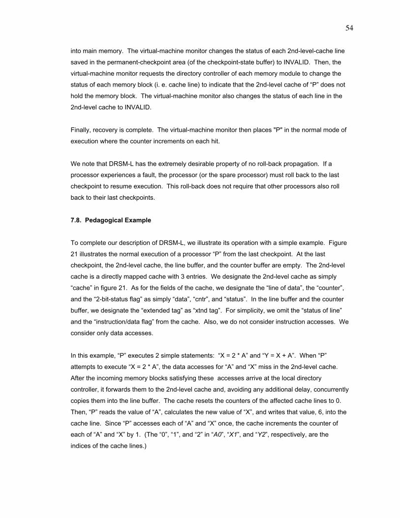
54
into main memory. The virtual-machine monitor changes the status of each 2nd-level-cache line
saved in the permanent-checkpoint area (of the checkpoint-state buffer) to INVALID. Then, the
virtual-machine monitor requests the directory controller of each memory module to change the
status of each memory block (i. e. cache line) to indicate that the 2nd-level cache of ÒPÓ does not
hold the memory block. The virtual-machine monitor also changes the status of each line in the
2nd-level cache to INVALID.
Finally, recovery is complete. The virtual-machine monitor then places "P" in the normal mode of
execution where the counter increments on each hit.
We note that DRSM-L has the extremely desirable property of no roll-back propagation. If a
processor experiences a fault, the processor (or the spare processor) must roll back to the last
checkpoint to resume execution. This roll-back does not require that other processors also roll
back to their last checkpoints.
7.8. Pedagogical Example
To complete our description of DRSM-L, we illustrate its operation with a simple example. Figure
21 illustrates the normal execution of a processor ÒPÓ from the last checkpoint. At the last
checkpoint, the 2nd-level cache, the line buffer, and the counter buffer are empty. The 2nd-level
cache is a directly mapped cache with 3 entries. We designate the 2nd-level cache as simply
ÒcacheÓ in figure 21. As for the fields of the cache, we designate the Òline of dataÓ, the ÒcounterÓ,
and the Ò2-bit-status flagÓ as simply ÒdataÓ, ÒcntrÓ, and ÒstatusÓ. In the line buffer and the counter
buffer, we designate the Òextended tagÓ as Òxtnd tagÓ. For simplicity, we omit the Òstatus of lineÓ
and the Òinstruction/data flagÓ from the cache. Also, we do not consider instruction accesses. We
consider only data accesses.
In this example, ÒPÓ executes 2 simple statements: ÒX = 2 * AÓ and ÒY = X + AÓ. When ÒPÓ
attempts to execute ÒX = 2 * AÓ, the data accesses for ÒAÓ and ÒXÓ miss in the 2nd-level cache.
After the incoming memory blocks satisfying these accesses arrive at the local directory
controller, it forwards them to the 2nd-level cache and, avoiding any additional delay, concurrently
copies them into the line buffer. The cache resets the counters of the affected cache lines to 0.
Then, ÒPÓ reads the value of ÒAÓ, calculates the new value of ÒXÓ, and writes that value, 6, into the
cache line. Since ÒPÓ accesses each of ÒAÓ and ÒXÓ once, the cache increments the counter of
each of ÒAÓ and ÒXÓ by 1. (The Ò0Ó, Ò1Ó, and Ò2Ó in ÒA0Ó, ÒX1Ó, and ÒY2Ó, respectively, are the
indices of the cache lines.)
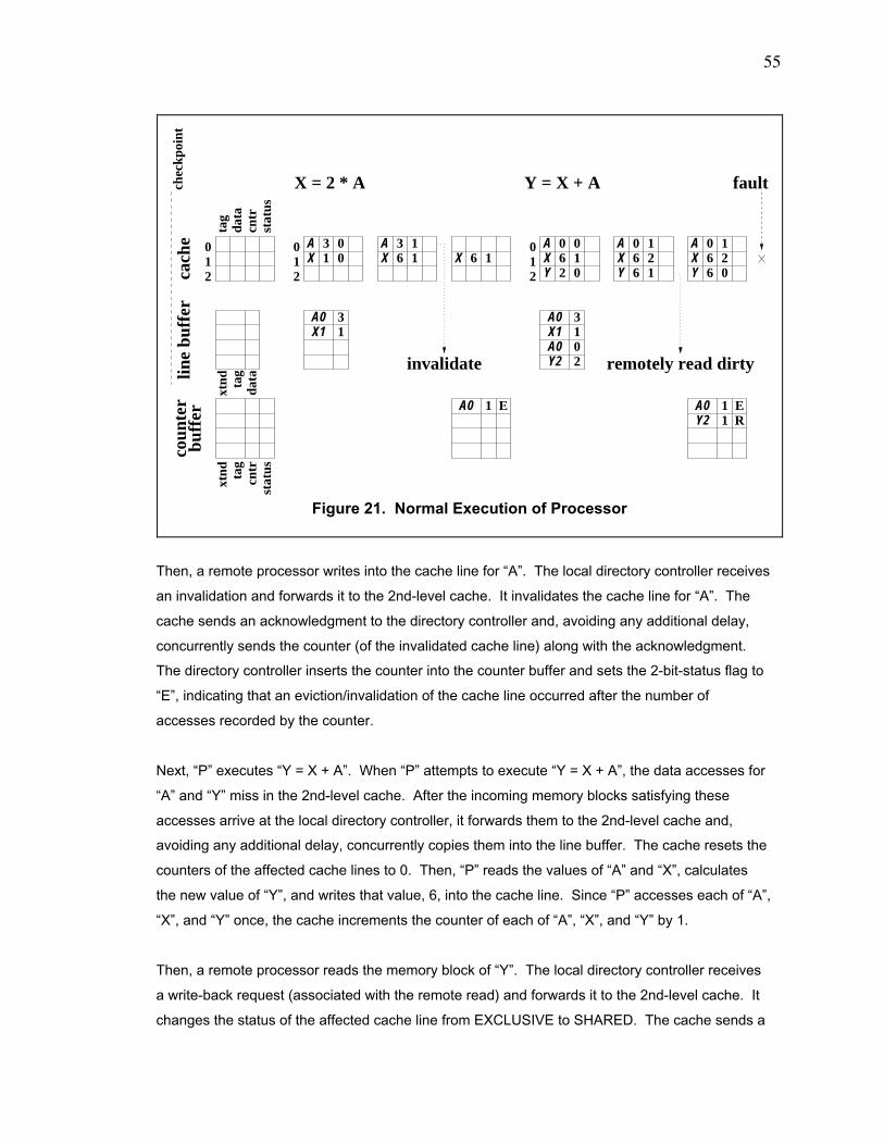
55
Then, a remote processor writes into the cache line for ÒAÓ. The local directory controller receives
an invalidation and forwards it to the 2nd-level cache. It invalidates the cache line for ÒAÓ. The
cache sends an acknowledgment to the directory controller and, avoiding any additional delay,
concurrently sends the counter (of the invalidated cache line) along with the acknowledgment.
The directory controller inserts the counter into the counter buffer and sets the 2-bit-status flag to
ÒEÓ, indicating that an eviction/invalidation of the cache line occurred after the number of
accesses recorded by the counter.
Next, ÒPÓ executes ÒY = X + AÓ. When ÒPÓ attempts to execute ÒY = X + AÓ, the data accesses for
ÒAÓ and ÒYÓ miss in the 2nd-level cache. After the incoming memory blocks satisfying these
accesses arrive at the local directory controller, it forwards them to the 2nd-level cache and,
avoiding any additional delay, concurrently copies them into the line buffer. The cache resets the
counters of the affected cache lines to 0. Then, ÒPÓ reads the values of ÒAÓ and ÒXÓ, calculates
the new value of ÒYÓ, and writes that value, 6, into the cache line. Since ÒPÓ accesses each of ÒAÓ,
ÒXÓ, and ÒYÓ once, the cache increments the counter of each of ÒAÓ, ÒXÓ, and ÒYÓ by 1.
Then, a remote processor reads the memory block of ÒYÓ. The local directory controller receives
a write-back request (associated with the remote read) and forwards it to the 2nd-level cache. It
changes the status of the affected cache line from EXCLUSIVE to SHARED. The cache sends a
chec
kpoi
nt
012
coun
ter
buff
erX = 2 * A
remotely read dirty
012
31
Y = X + A
210
13
20
invalidate
1 11
E ER
A0X1
A0X1A0Y2
A0 A0Y2
AX 1
3 00 X 16
AX 6
3 11
AXY
62
0 010
AXY 6
21
160 A
YX
6 0
0 16 2
tag
data
stat
uscn
trst
atus
cntr
tag
tag
xtnd
data
xtndlin
e bu
ffer
cach
efault
Figure 21. Normal Execution of Processor
56
copy of both the data and the counter in the line to the directory controller and concurrently resets
the counter to 0. The directory controller inserts the counter into the counter buffer and sets the
2-bit-status flag to ÒRÓ, indicating that a remote read of the cache line occurred after the number
of accesses recorded by the counter.
Now, we suppose that a fault occurs at this point. Figure 22 illustrates how ÒPÓ performs
recovery and, specifically, how ÒPÓ reproduces the exact same dirty value that ÒPÓ produced prior
to the fault.
The recovery-logic circuit resets ÒPÓ. (If ÒPÓ experienced a permanent fault, the recovery-logic
circuit replaces the failed processor module with a spare processor module, and the spare
processor becomes ÒPÓ.) ÒPÓ enters the virtual-machine monitor. It loads the 2nd-level cache
with the contents of the cache saved at the last checkpoint. For each line in the cache, the
virtual-machine monitor resets the counter to 0 and sets the 2-bit-status flag to ÒVÓ. (In our simple
example, the contents of the cache saved at the last checkpoint is empty and has no valid lines.)
The virtual-machine monitor also loads ÒPÓ with the processor state saved at the last checkpoint.
Next, the virtual-machine monitor groups the entries (by the 2nd-level-cache index of the
extended tag) of the line buffer and the counter buffer and places the entries into the sorted-line
buffer and the sorted-counter buffer. The grouping procedure maintains, for each cache index,
chec
kpoi
ntca
che
sort
ed li
ne
012
buff
er
X = 2 * A
012
Y = X + A
210
invalidate
A0
remotely read dirtyY2 22 Y2
3
A0 1Y2 1
ER Y2 1 R
AX 1
3 10
AX 6
3 00 X
A6 03 0 A
XY
62 1
00 0
XY
A
660 0
00
XY
A
600
0 06
EN
E EN N
RNN N N
NR
NR
data
cntr
stat
us
tag
xtnd ta
gda
ta
xtnd ta
gcn
trst
atus
buff
erso
rted
cou
nter
A0X1
01
A0 0
Figure 22. Recovery of Processor
57
the temporal order in which the entries were originally inserted into the line buffer and the counter
buffer.
Then, ÒPÓ proceeds to execute in recovery mode. When ÒPÓ attempts to execute ÒX = 2 * AÓ, the
data accesses for ÒAÓ and ÒXÓ miss in the 2nd-level cache. Execution traps to the virtual-machine
monitor. To satisfy each of these misses, the virtual-machine monitor retrieves the next matching
entry from the sorted-line buffer and the next matching entry from the sorted-counter buffer and
places the contents of the entries into the appropriate cache line. Since the sorted-counter buffer
has no matching entry for ÒXÓ, the virtual-machine monitor resets the counter in the cache line for
ÒXÓ to 0 and sets the 2-bit-status flag in that cache line to ÒNÓ (meaning Òno eventÓ). Then, ÒPÓ
reads the value of ÒAÓ, calculates the new value of ÒXÓ, writes that value, 6, into the cache line.
Since ÒPÓ accesses each of ÒAÓ and ÒXÓ once, the cache decrements the counter of each of ÒAÓ
and ÒXÓ by 1 if the counter is not 0. If the counter is already 0, the counter is not decremented.
At this point in the previous normal execution, an invalidation arrives at the 2nd-level cache.
Figure 22 illustrates this event with an italicized label.
Next, ÒPÓ executes ÒY = X + AÓ. When ÒPÓ attempts to execute ÒY = X + AÓ, the data access for
ÒAÓ hits in the 2nd-level cache. It discovers that the counter for ÒAÓ is 0, and since the 2-bit-status
flag is not ÒNÓ, execution traps to the virtual-machine monitor. It then acts on the value of the 2-
bit-status flag. Since it is ÒEÓ and indicates that the cache line was evicted/invalidated, the virtual-
machine monitor retrieves the next matching entry from the sorted-line buffer and the next
matching entry from the sorted-counter buffer and places the contents of the entries into the
cache line for ÒAÓ. Since the sorted-counter buffer has no matching entry for ÒAÓ, the virtual-
machine monitor resets the counter in the cache line for ÒAÓ to 0 and sets the 2-bit-status flag in
that cache line to ÒNÓ (meaning Òno eventÓ).
The data access for ÒXÓ also hits in the 2nd-level cache. It discovers that the counter for ÒXÓ is 0,
but since the 2-bit-status flag is ÒNÓ, execution does not trap to the virtual-machine monitor.
The data access for ÒYÓ misses in the cache. To handle the access miss on ÒYÓ, the virtual-
machine monitor retrieves the next matching entry from the sorted-line buffer and the next
matching entry from the sorted-counter buffer and places the contents of the entries into the
cache line for ÒYÓ.
Then, ÒPÓ reads the values of ÒAÓ and ÒXÓ, calculates the new value of ÒYÓ, and writes that value,
6, into the cache line. Since ÒPÓ accesses each of ÒAÓ, ÒXÓ, and ÒYÓ once, the cache decrements
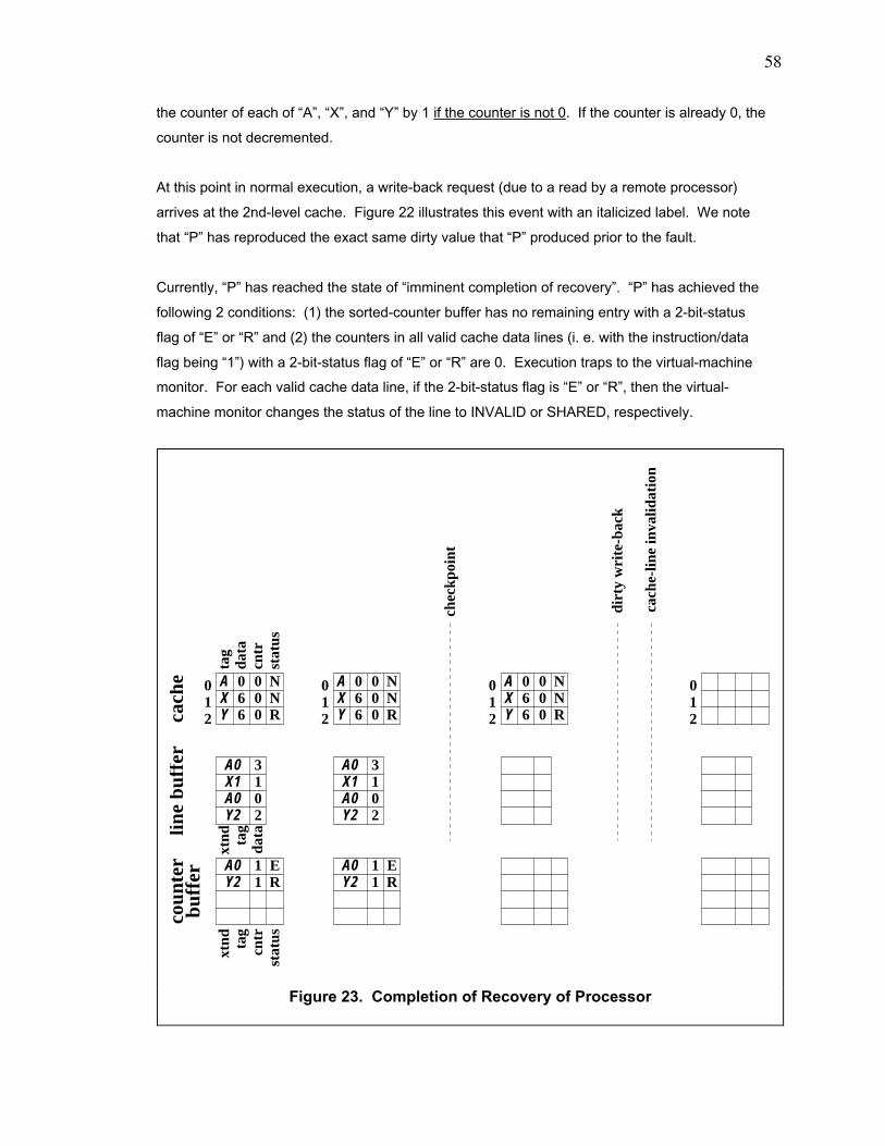
58
the counter of each of ÒAÓ, ÒXÓ, and ÒYÓ by 1 if the counter is not 0. If the counter is already 0, the
counter is not decremented.
At this point in normal execution, a write-back request (due to a read by a remote processor)
arrives at the 2nd-level cache. Figure 22 illustrates this event with an italicized label. We note
that ÒPÓ has reproduced the exact same dirty value that ÒPÓ produced prior to the fault.
Currently, ÒPÓ has reached the state of Òimminent completion of recoveryÓ. ÒPÓ has achieved the
following 2 conditions: (1) the sorted-counter buffer has no remaining entry with a 2-bit-status
flag of ÒEÓ or ÒRÓ and (2) the counters in all valid cache data lines (i. e. with the instruction/data
flag being Ò1Ó) with a 2-bit-status flag of ÒEÓ or ÒRÓ are 0. Execution traps to the virtual-machine
monitor. For each valid cache data line, if the 2-bit-status flag is ÒEÓ or ÒRÓ, then the virtual-
machine monitor changes the status of the line to INVALID or SHARED, respectively.
cach
ebu
ffer
line
buff
erco
unte
r
A0
Y2 2
3
A0 1Y2 1
cach
e-lin
e in
valid
atio
n
ER
X1 1A0 0
012
data
cntr
stat
us
tag
xtnd ta
gcn
trst
atus
A0
Y2 2
3
A0 1Y2 1
ER
xtnd ta
gda
ta
X1 1A0 0
XY
A
600
0 06
NNR
chec
kpoi
nt
012
XY
A
600
0 06
NNR
012
XY
A
600
0 06
NNR
dirt
y w
rite
-bac
k
012
Figure 23. Completion of Recovery of Processor
59
To complete the recovery from the fault, the virtual-machine monitor invokes ÒPÓ to establish a
checkpoint, indicated in figure 23. Establishing the checkpoint clears the line buffer and the
counter buffer and resets all the counters in the 2nd-level cache to 0. Once the checkpoint is
established, the virtual-machine monitor reads each dirty 2nd-level-cache line saved in the
permanent-checkpoint area of the checkpoint-state buffer and writes the line back into main
memory. The virtual-machine monitor changes the status of each 2nd-level-cache line saved in
the permanent-checkpoint area (of the checkpoint-state buffer) to INVALID. Then, the virtual-
machine monitor tells the directory controller of each memory module to change the status of
each memory block (i. e. cache line) to indicate that the 2nd-level cache of ÒPÓ does not hold the
memory block. The virtual-machine monitor also changes the status of each line in the 2nd-level
cache (of ÒPÓ) to INVALID. The contents of the 2nd-level cache are now consistent with the
information stored in the directories of the memory modules. ÒPÓ resumes normal execution.
ÒPÓ must establish a checkpoint at the end of recovery in order to deal with the loss of counter
values after a fault. The last values of the counters for ÒAÓ and ÒXÓ in figure 21 are 1 and 2,
respectively. Both 1 and 2 are lost after the fault occurs.
7.9. Optimal Size of Line Buffer and Counter Buffer
For a given amount of silicon area from which we can build the line buffer and the counter buffer,
we show that the optimal size of each is one where the ratio of the number of entries in the
counter buffer to the number of entries in the line buffer equals the ratio of the rate at which the
counter buffer fills to the rate at which the line buffer fills. Suppose that we have the following
parameters.
Then, considering only checkpoints triggered by overflowing a buffer, we have the following
equations.
E[CB] = number of entries in the counter buffer E[LB] = number of entries in the line buffer A(T, E) = amount of silicon area consumed by transistors to
implement "E" entries for buffer of type ÒTÓ AA = fixed amount of allocated silicon area in which to
implement counter buffer and line buffer R[CB] = rate at which counter buffer fills in terms of the number
of entries per unit time R[LB] = rate at which line buffer fills in terms of the number of
entries per unit time RC = rate of establishing checkpoints
60
A(Òcounter bufferÓ, E[CB]) + A(Òline bufferÓ, E[LB]) = AA (equation #1)
RC = max (R[CB] / E[CB], R[LB] / E[LB]) (equation #2)
The optimum size of each of the counter buffer and the line buffer arises when the "RC", rate of
establishing checkpoints, is minimum. Suppose that we select "E[CB]" and "E[LB]" to be
"E0[CB]" and "E0[LB]", respectively, where
RC = max (R[CB] / E0[CB], R[LB] / E0[LB]) (equation #3)
= R[CB] / E0[CB] = R[LB] / E0[LB]. (equation #4)
Now, we consider what happens when we increase "E[CB]" or decrease it. Suppose that we
increase it to some value "E2[CB]" such that "E2[CB]" is greater than "E0[CB]". By equation #1,
"E[LB]" must decrease to some value, say "E2[LB]. Then, we have that
RC = max (R[CB] / E2[CB], R[LB] / E2[LB]) (equation #5)
= R[LB] / E2[LB]. (equation #6)
On the other hand, suppose that we decrease "E[CB]" to some value "E1[CB]"such that "E1[CB]"
is less than "E0[CB]". By equation #1, "E[LB]" must increase to some value, say "E1[LB]. Then,
we have that
RC = max (R[CB] / E1[CB], R[LB] / E1[LB]) (equation #7)
= R[CB] /E1[CB]. (equation #8)
Comparing equation #4, equation #6, and equation #8, we see that "RC" is smallest when
"E[CB]" equals "E0[CB]". Hence, the optimum ratio of "E[CB]" to "E[LB]" is one where
E[CB] / E[LB] = R[CB] / R[LB]. (equation #9)
7.10. Detailed Description
In Appendix A, we precisely describe the operation of DRSM-L by using C-like code.

61
Chapter 8. Simulation Environment and Benchmarks
8.1. Multiprocessor Simulator
We evaluate DRSM, DRSM-C, DRSM-H, and DRSM-L by simulating their operation within a
multiprocessor simulator. The block diagram of the base multiprocessor in our simulator appears
in figure 24, illustrating a 2-processor configuration. The model of the memory system and the
network is the NUMA model packaged with the SimOS simulator [4]. Instead of SimOS, we use
our own simulator, ABSS, to simulate the processors and to drive the model of the memory
system and the network. ABSS is an augmentation-based simulator that runs significantly faster
than SimOS [12]. Our simulator has the following parameters.
SCACHE_HIT_TIME
netw
ork
NU
MA
_NE
T_T
IME
memorymodule
NUMA_MEM_TIME
controller
directoryNUMA_BUS_TIME
cache
2nd-level
NUMA_NILOCAL_DC_TIME
NUMA_PIREMOTE_DC_TIME
NUMA_NIREMOTE_DC_TIME
NUMA_PILOCAL_DC_TIME
processor
1st-level
cache
instruct.
1st-level
data
cache
SCACHE_HIT_TIME
memorymodule
NUMA_MEM_TIME
controller
directoryNUMA_BUS_TIME
cache
2nd-level
NUMA_NILOCAL_DC_TIMENUMA_NIREMOTE_DC_TIME
NUMA_PIREMOTE_DC_TIMENUMA_PILOCAL_DC_TIME
processor
1st-level
cache
instruct.
1st-level
cache
data
Figure 24. Base Multiprocessor

62
In particular, we assume that the amount of data in the processor state (i. e. the internal registers
of the processor) is identical to the amount of data in 16 2nd-level-cache lines.
8.2. Benchmarks
In ABSS , We run 6 benchmarks -- Cholesky, FFT, LU, ocean, radix, and water -- from the
SPLASH2 suite [16] . Cholesky factors a sparse matrix. FFT performs a fast Fourier transform.
explanatory notesA cycle is a 200-megahertz-processor cycle.
base parametersprocessor = SPARC V7 @ 200 megahertzprocessor state = equivalent of 16 2nd-level-cache lines of datacache policy = write-backmemory model = sequential consistency
1st-level instruction cache = 32 kilobytes with 4-way set associativity, 2 states (INVALID and SHARED), 64-byte line1st-level data cache = 32 kilobytes with 4-way set associativity, 3 states (INVALID, SHARED, and EXCLUSIVE), 64-byte line2nd-level cache = 1 megabyte with 4-way set associativity, 3 states (INVALID, SHARED, and EXCLUSIVE), 128-byte line
average delay (NUMA_BUS_TIME) between 2nd-level cache and directory controller (DC) = 75 cyclesaverage delay (SCACHE_HIT_TIME) for access that hits in the 2nd-level cache = 50 cyclesaverage delay (NUMA_PILOCAL_DC_TIME) in the local DC for local access = 100 cyclesaverage delay (NUMA_PIREMOTE_DC_TIME) in the local DC for remote access = 25 cyclesaverage delay (NUMA_NILOCAL_DC_TIME) in the remote DC for remote access = 350 cyclesaverage delay (NUMA_NIREMOTE_DC_TIME) in the remote DC for remote reply = 25 cyclesaverage network delay (NUMA_NET_TIME) between 2 DCs = 150 cyclesaverage delay (NUMA_MEM_TIME) to access memory = 50 cycles
DRSM-H parametersmemory cache = 2 entries2nd-level cache = 4 states (INVALID, SHARED, DIRTY_SHARED, and EXCLUSIVE)
DRSM-L parameterswidth of counter = 32 bitsline buffer = 8192 entriescounter buffer = 8192 entriestimer = expiration per 20 million cycles
63
LU factors a dense matrix. Ocean simulates eddy and boundary currents in oceans. Radix
performs a radix sort. Finally, water evaluates the forces and the potentials as they change over
time among water molecules.
Woo presents a detailed study of these benchmarks [16]. They have 3 common characteristics.
First, the working set of each benchmark fits within the large 2nd-level cache of our TCMP.
Second, these benchmarks represent a scientific workload. They are useful in representing a
wide variety of memory-access patterns but do virtually no communication with the environment
outside of the TCMP. So, establishing an external-communication-triggered checkpoint does not
arise in our simulations. Third, these benchmarks invoke exactly one thread to run per processor.
So, establishing a context-switch-triggered checkpoint does not arise in our simulations. We note
that regardless of the event triggering the establishment of a checkpoint, the procedure for
establishing a checkpoint remains the same. Hence, we can still evaluate the performance of our
hardware-based algorithms even if checkpoint establishment is triggered by a smaller set of
events.

64
Chapter 9. Results and Analysis
9.1. Overall Performance of Benchmarks
Figures 25, 26, 27, 28, 29, and 30 show the performance of the 6 application benchmarks running
on 5 TCMPs: the base system (which is a TCMP without any special hardware for establishing
checkpoints), the system with DRSM, the system with DRSM-C, the system with DRSM-H, and
the system with DRSM-L. We set the number of processors to 8, 16, and 32. We decompose
the execution time into 5 categories: non-idle time of the processor, the instruction stall, the lock
stall, the data stall, and the barrier stall. (In the figures, we occasionally designate a processor as
a ÒCPUÓ, the acronym for Òcentral processing unitÓ.) In general, the performance of DRSM-L
exceeds the performance of DRSM, DRSM-C, and DRSM-H.
We see 2 notable effects. First, for all benchmarks except Cholesky, the barrier stall and the lock
stall increase substantially as the number of processors increases from 8 to 32 because all
benchmarks except Cholesky have several global barriers and global locks. Both the locks within
global barriers and the global locks, where all processors compete for a lock, cause hot spots to
arise at the memory addresses holding the locks. In Cholesky, after the processors enter the
main loop of execution, they encounter no global synchronization. Hence, Cholesky does not
suffer this problem.
Second, the checkpointing algorithm can occasionally cause a TCMP with DRSM, DRSM-C, or
DRSM-H to exceed the performance of the base TCMP. Figure 31 illustrates the explanation for
this effect. In the base system, the transfer of dirty data from processor "Q" to processor "P"
typically involves the following activities. "P" suffers a read miss in the local cache. "P" sends
message "M1" to the remote memory module "R". It sends a request "M2" to "Q" to retrieve the
dirty data. "Q" replies to "R" with message "M3". "R" forwards the data to "P" in message "M4".
This type of communication involves 4 messages: "M1", "M2", "M3", and "M4".
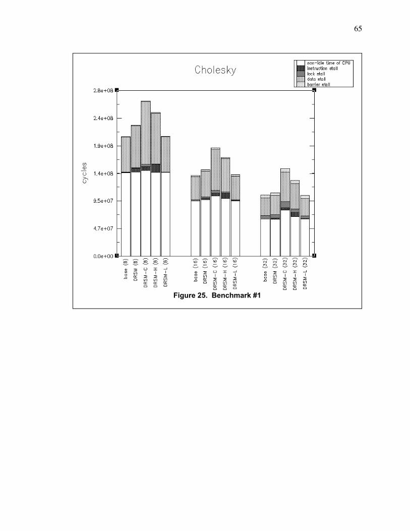
65
Figure 25. Benchmark #1
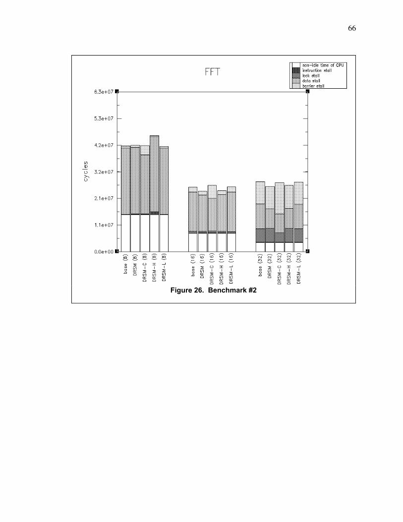
66
Figure 26. Benchmark #2

67
Figure 27. Benchmark #3
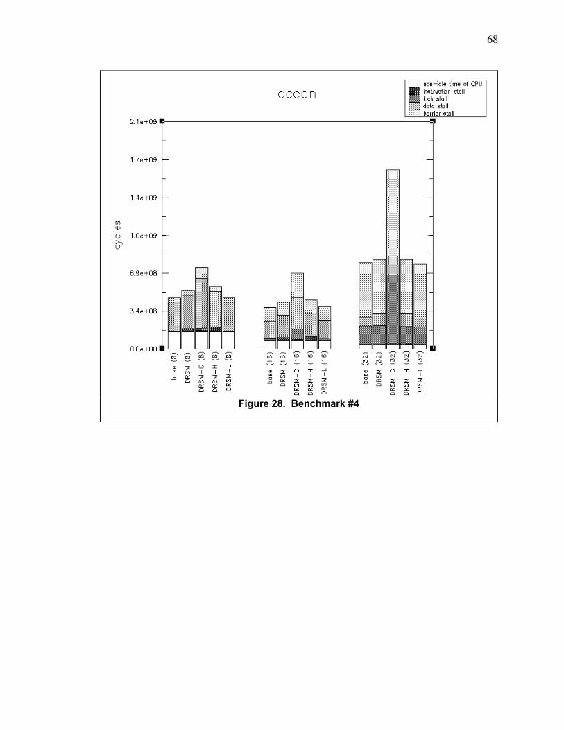
68
Figure 28. Benchmark #4
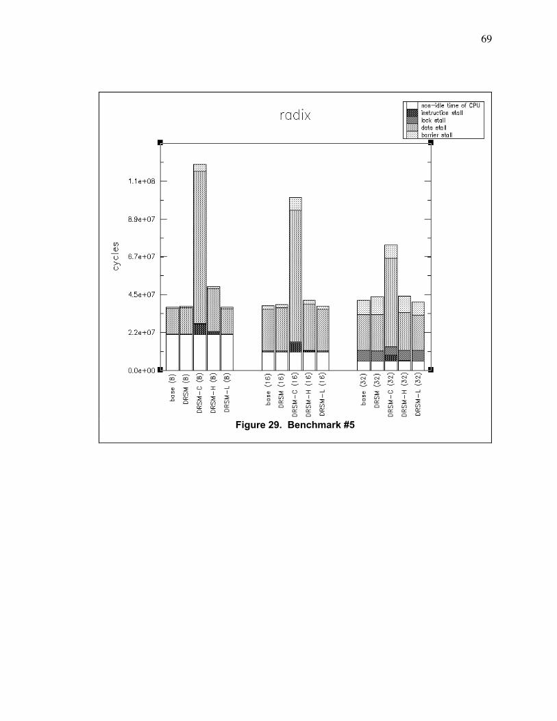
69
Figure 29. Benchmark #5
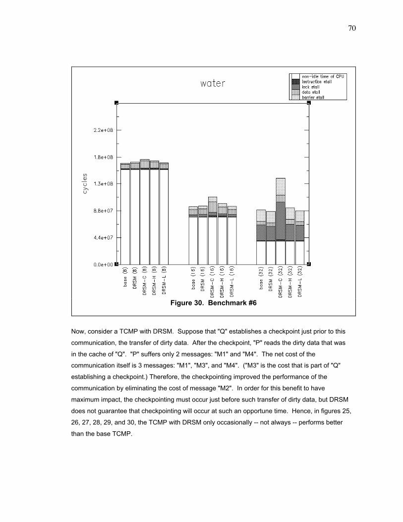
70
Now, consider a TCMP with DRSM. Suppose that "Q" establishes a checkpoint just prior to this
communication, the transfer of dirty data. After the checkpoint, "P" reads the dirty data that was
in the cache of "Q". "P" suffers only 2 messages: "M1" and "M4". The net cost of the
communication itself is 3 messages: "M1", "M3", and "M4". ("M3" is the cost that is part of "Q"
establishing a checkpoint.) Therefore, the checkpointing improved the performance of the
communication by eliminating the cost of message "M2". In order for this benefit to have
maximum impact, the checkpointing must occur just before such transfer of dirty data, but DRSM
does not guarantee that checkpointing will occur at such an opportune time. Hence, in figures 25,
26, 27, 28, 29, and 30, the TCMP with DRSM only occasionally -- not always -- performs better
than the base TCMP.
Figure 30. Benchmark #6
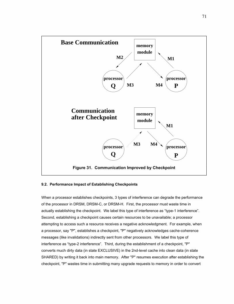
71
9.2. Performance Impact of Establishing Checkpoints
When a processor establishes checkpoints, 3 types of interference can degrade the performance
of the processor in DRSM, DRSM-C, or DRSM-H. First, the processor must waste time in
actually establishing the checkpoint. We label this type of interference as Òtype-1 interferenceÓ.
Second, establishing a checkpoint causes certain resources to be unavailable; a processor
attempting to access such a resource receives a negative acknowledgment. For example, when
a processor, say "P", establishes a checkpoint, "P" negatively acknowledges cache-coherence
messages (like invalidations) indirectly sent from other processors. We label this type of
interference as Òtype-2 interferenceÓ. Third, during the establishment of a checkpoint, "P"
converts much dirty data (in state EXCLUSIVE) in the 2nd-level cache into clean data (in state
SHARED) by writing it back into main memory. After "P" resumes execution after establishing the
checkpoint, "P" wastes time in submitting many upgrade requests to memory in order to convert
M2
M3 M4
M1
memory
Communication
module
Pprocessorprocessor
Q
Base Communication
memorymodule
M1
M4M3
Q P
processorprocessor
after Checkpoint
Figure 31. Communication Improved by Checkpoint
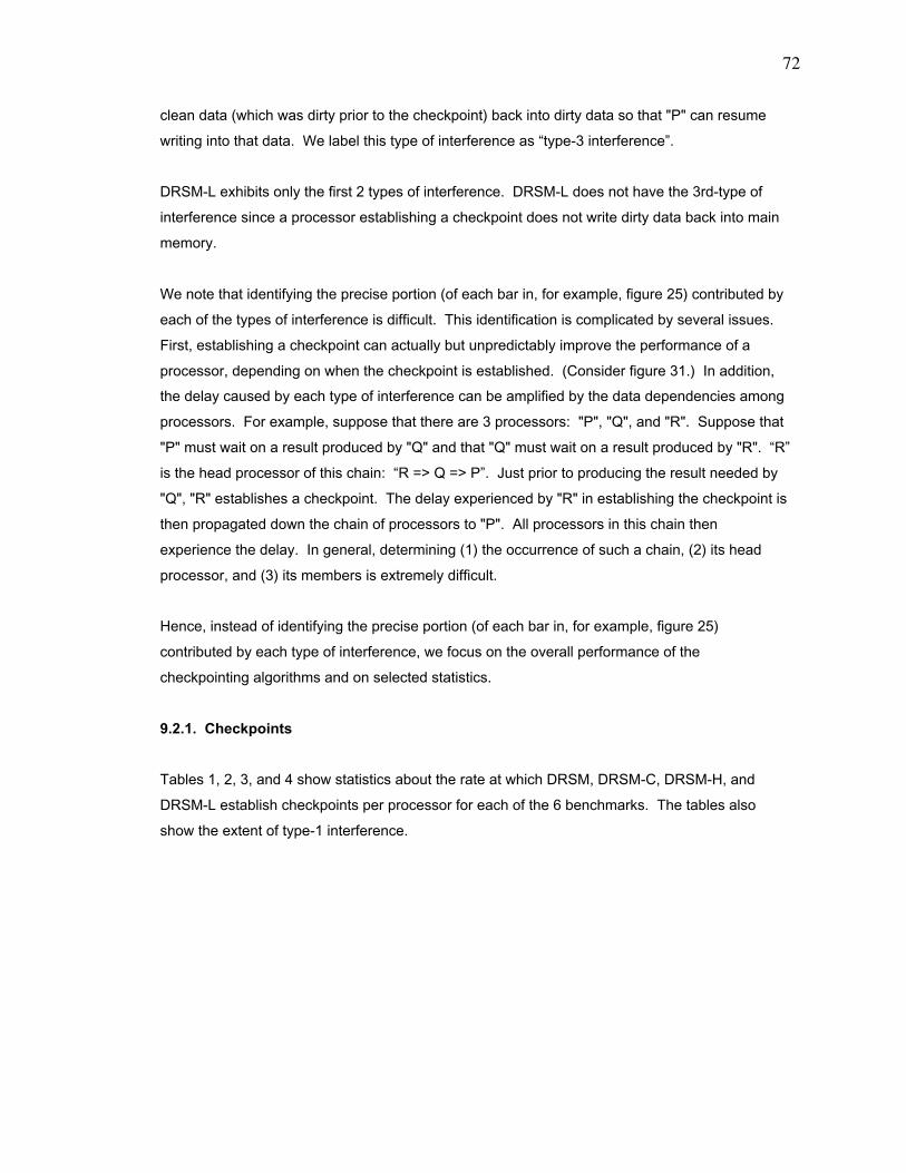
72
clean data (which was dirty prior to the checkpoint) back into dirty data so that "P" can resume
writing into that data. We label this type of interference as Òtype-3 interferenceÓ.
DRSM-L exhibits only the first 2 types of interference. DRSM-L does not have the 3rd-type of
interference since a processor establishing a checkpoint does not write dirty data back into main
memory.
We note that identifying the precise portion (of each bar in, for example, figure 25) contributed by
each of the types of interference is difficult. This identification is complicated by several issues.
First, establishing a checkpoint can actually but unpredictably improve the performance of a
processor, depending on when the checkpoint is established. (Consider figure 31.) In addition,
the delay caused by each type of interference can be amplified by the data dependencies among
processors. For example, suppose that there are 3 processors: "P", "Q", and "R". Suppose that
"P" must wait on a result produced by "Q" and that "Q" must wait on a result produced by "R". ÒRÓ
is the head processor of this chain: ÒR => Q => PÓ. Just prior to producing the result needed by
"Q", "R" establishes a checkpoint. The delay experienced by "R" in establishing the checkpoint is
then propagated down the chain of processors to "P". All processors in this chain then
experience the delay. In general, determining (1) the occurrence of such a chain, (2) its head
processor, and (3) its members is extremely difficult.
Hence, instead of identifying the precise portion (of each bar in, for example, figure 25)
contributed by each type of interference, we focus on the overall performance of the
checkpointing algorithms and on selected statistics.
9.2.1. Checkpoints
Tables 1, 2, 3, and 4 show statistics about the rate at which DRSM, DRSM-C, DRSM-H, and
DRSM-L establish checkpoints per processor for each of the 6 benchmarks. The tables also
show the extent of type-1 interference.
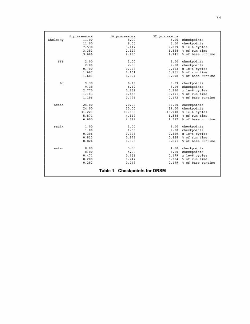
73
8 processors 16 processors 32 processorsCholesky 11.00 8.00 6.00 checkpoints 11.00 8.00 6.00 checkpoints 7.530 3.447 2.039 x 1e+6 cycles 3.353 2.327 1.868 % of run time 3.666 2.485 1.941 % of base runtime
FFT 2.00 2.00 2.00 checkpoints 2.00 2.00 2.00 checkpoints 0.700 0.278 0.193 x 1e+6 cycles 1.667 1.161 0.751 % of run time 1.681 1.094 0.698 % of base runtime
LU 9.38 6.19 5.09 checkpoints 9.38 6.19 5.09 checkpoints 2.775 0.832 0.280 x 1e+6 cycles 1.143 0.466 0.171 % of run time 1.196 0.476 0.172 % of base runtime
ocean 24.00 20.00 39.00 checkpoints 24.00 20.00 39.00 checkpoints 31.227 17.650 10.910 x 1e+6 cycles 5.871 4.117 1.338 % of run time 6.695 4.649 1.392 % of base runtime
radix 1.00 1.00 2.00 checkpoints 1.00 1.00 2.00 checkpoints 0.306 0.378 0.359 x 1e+6 cycles 0.813 0.974 0.828 % of run time 0.824 0.995 0.871 % of base runtime
water 8.00 5.00 4.00 checkpoints 8.00 5.00 4.00 checkpoints 0.471 0.238 0.179 x 1e+6 cycles 0.280 0.247 0.204 % of run time 0.282 0.249 0.199 % of base runtime
Table 1. Checkpoints for DRSM

74
8 processors 16 processors 32 processorsCholesky 437.9 520.1 682.1 checkpoints (0.4 + 437.5) (0.0 + 520.1) (0.0 + 682.1) checkpoints (0.071 + 6.655) (0.000 + 4.776) (0.000 + 4.572) x 1e+6 cycles (0.027 + 2.496) (0.000 + 2.564) (0.000 + 3.042) % of run time (0.035 + 3.240) (0.000 + 3.443) (0.000 + 4.353) % of base runtime
FFT 18.0 21.4 24.5 checkpoints (0.0 + 18.0) (0.0 + 21.4) (0.0 + 24.5) checkpoints (0.000 + 0.509) (0.000 + 0.308) (0.000 + 0.337) x 1e+6 cycles (0.000 + 1.214) (0.000 + 1.178) (0.000 + 1.236) % of run time (0.000 + 1.222) (0.000 + 1.213) (0.000 + 1.219) % of base runtime
LU 75.4 77.4 81.8 checkpoints (1.4 + 74.0) (1.2 + 76.2) (1.1 + 80.7) checkpoints (0.112 + 1.957) (0.038 + 0.990) (0.017 + 1.034) x 1e+6 cycles (0.043 + 0.752) (0.020 + 0.516) (0.010 + 0.586) % of run time (0.048 + 0.844) (0.022 + 0.567) (0.011 + 0.636) % of base runtime
ocean 2446.6 3161.9 4088.8 checkpoints (0.0 + 2446.6) (0.0 + 3161.9) (0.0 + 4088.8) checkpoints (0.000 + 24.827) (0.000 + 22.740) (0.000 + 32.389) x 1e+6 cycles (0.000 + 3.341) (0.000 + 3.291) (0.000 + 1.989) % of run time (0.000 + 5.323) (0.000 + 5.990) (0.000 + 4.132) % of base runtime
radix 380.0 584.6 606.1 checkpoints (0.2 + 379.8) (0.0 + 584.6) (0.0 + 606.1) checkpoints (0.020 + 6.643) (0.000 + 6.494) (0.000 + 4.900) x 1e+6 cycles (0.016 + 5.489) (0.000 + 6.397) (0.000 + 6.635) % of run time (0.053 + 17.858) (0.000 + 17.098) (0.000 + 11.869) % of base runtime
water 189.9 770.9 580.6 checkpoints (1.0 + 188.9) (0.0 + 770.9) (0.0 + 580.5) checkpoints (0.001 + 0.953) (0.000 + 2.804) (0.000 + 3.102) x 1e+6 cycles (0.001 + 0.552) (0.000 + 2.514) (0.000 + 2.185) % of run time (0.001 + 0.570) (0.000 + 2.931) (0.000 + 3.456) % of base runtime
Table 2. Checkpoints for DRSM-C
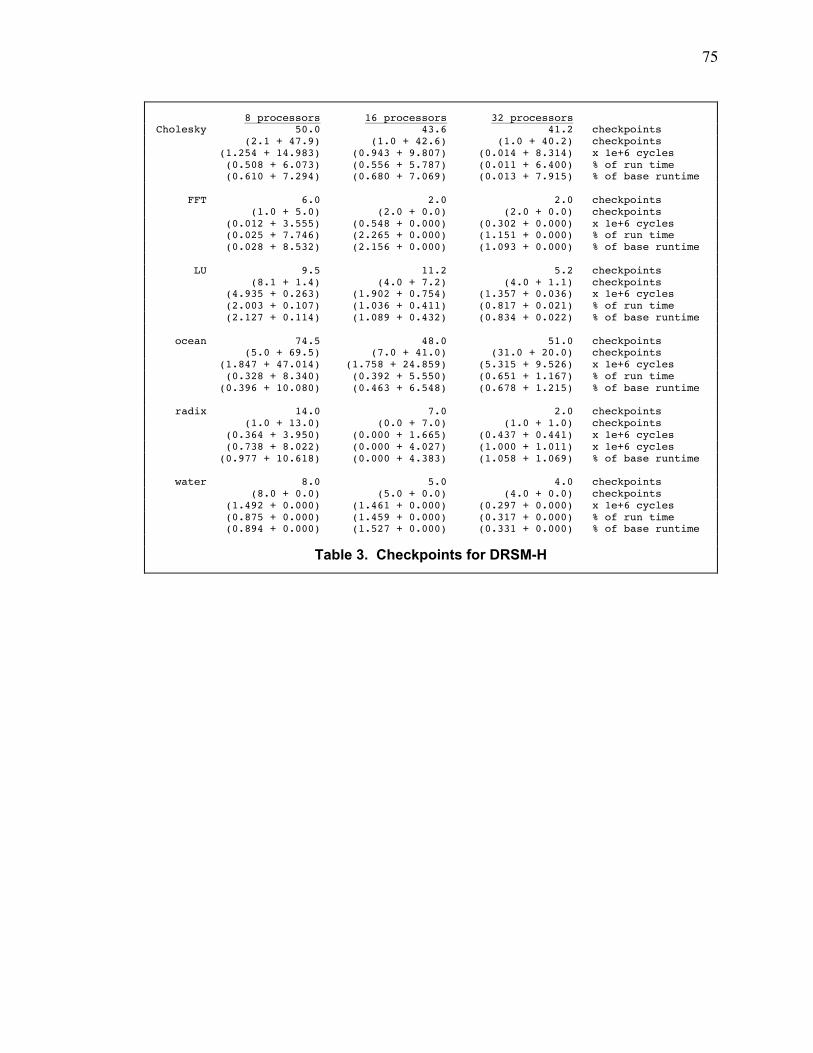
75
8 processors 16 processors 32 processorsCholesky 50.0 43.6 41.2 checkpoints (2.1 + 47.9) (1.0 + 42.6) (1.0 + 40.2) checkpoints (1.254 + 14.983) (0.943 + 9.807) (0.014 + 8.314) x 1e+6 cycles (0.508 + 6.073) (0.556 + 5.787) (0.011 + 6.400) % of run time (0.610 + 7.294) (0.680 + 7.069) (0.013 + 7.915) % of base runtime
FFT 6.0 2.0 2.0 checkpoints (1.0 + 5.0) (2.0 + 0.0) (2.0 + 0.0) checkpoints (0.012 + 3.555) (0.548 + 0.000) (0.302 + 0.000) x 1e+6 cycles (0.025 + 7.746) (2.265 + 0.000) (1.151 + 0.000) % of run time (0.028 + 8.532) (2.156 + 0.000) (1.093 + 0.000) % of base runtime
LU 9.5 11.2 5.2 checkpoints (8.1 + 1.4) (4.0 + 7.2) (4.0 + 1.1) checkpoints (4.935 + 0.263) (1.902 + 0.754) (1.357 + 0.036) x 1e+6 cycles (2.003 + 0.107) (1.036 + 0.411) (0.817 + 0.021) % of run time (2.127 + 0.114) (1.089 + 0.432) (0.834 + 0.022) % of base runtime
ocean 74.5 48.0 51.0 checkpoints (5.0 + 69.5) (7.0 + 41.0) (31.0 + 20.0) checkpoints (1.847 + 47.014) (1.758 + 24.859) (5.315 + 9.526) x 1e+6 cycles (0.328 + 8.340) (0.392 + 5.550) (0.651 + 1.167) % of run time (0.396 + 10.080) (0.463 + 6.548) (0.678 + 1.215) % of base runtime
radix 14.0 7.0 2.0 checkpoints (1.0 + 13.0) (0.0 + 7.0) (1.0 + 1.0) checkpoints (0.364 + 3.950) (0.000 + 1.665) (0.437 + 0.441) x 1e+6 cycles (0.738 + 8.022) (0.000 + 4.027) (1.000 + 1.011) x 1e+6 cycles (0.977 + 10.618) (0.000 + 4.383) (1.058 + 1.069) % of base runtime
water 8.0 5.0 4.0 checkpoints (8.0 + 0.0) (5.0 + 0.0) (4.0 + 0.0) checkpoints (1.492 + 0.000) (1.461 + 0.000) (0.297 + 0.000) x 1e+6 cycles (0.875 + 0.000) (1.459 + 0.000) (0.317 + 0.000) % of run time (0.894 + 0.000) (1.527 + 0.000) (0.331 + 0.000) % of base runtime
Table 3. Checkpoints for DRSM-H

76
We shall explain how to read the most complicated table, table 4, first. For each application,
there are 4 rows of statistics. The 1st row indicates the total number of checkpoints established
per processor. DRSM-L has effectively 3 events that trigger the establishment of a checkpoint;
they are (1) timer expiration, (2) line-buffer overflow, and (3) counter-buffer overflow. The
checkpoints that are attributed to each trigger appear in the 2nd row of statistics. For example, in
the 2nd row for Cholesky running on an 8-processor TCMP, we see Ò(9.62 + 0.12 + 0.62)Ó. The
number of timer-triggered checkpoints, line-buffer-triggered checkpoints, and counter-buffer-
triggered checkpoints are 9.62, 0.12, and 0.62, respectively.
The remaining 3 rows show the time consumed by checkpoint establishment. The 3rd row shows
the number of cycles for which a processor is stalled in establishing the number of checkpoints in
the 2nd row. Each number within parentheses in the 3rd row indicates a fraction of 10,000
cycles. For each number (of cycles) in the 3rd row, the 4th row shows the percentage of the total
execution time of the benchmark running on a TCMP with DRSM-L, and the 5th row shows the
percentage of the total execution time of the benchmark running on a base TCMP. For example,
during the execution of the Cholesky benchmark by the 8-processor TCMP, a typical processor
8 processors 16 processors 32 processorsCholesky 10.38 7.00 5.19 checkpoints (9.62 + 0.12 + 0.62) (6.94 + 0.00 + 0.06) (5.03 + 0.12 + 0.03) checkpoints (8.189 + 0.106 + 0.532) (5.902 + 0.000 + 0.055) (4.281 + 0.106 + 0.027) x1e+4 cycle (3.977 + 0.052 + 0.258) (4.229 + 0.000 + 0.040) (4.109 + 0.102 + 0.026) x0.01% time (3.987 + 0.052 + 0.259) (4.254 + 0.000 + 0.040) (4.075 + 0.101 + 0.025) x0.01% time
FFT 2.00 1.31 1.34 checkpoints (1.88 + 0.00 + 0.12) (1.25 + 0.00 + 0.06) (1.31 + 0.00 + 0.03) checkpoints (1.595 + 0.000 + 0.106) (1.063 + 0.000 + 0.058) (1.117 + 0.000 + 0.030) x1e+4 cycle (3.831 + 0.000 + 0.255) (4.146 + 0.000 + 0.224) (4.060 + 0.000 + 0.109) x0.01% time (3.829 + 0.000 + 0.255) (4.184 + 0.000 + 0.226) (4.039 + 0.000 + 0.108) x0.01% time
LU 7.50 4.88 4.12 checkpoints (7.50 + 0.00 + 0.00) (4.81 + 0.00 + 0.06) (4.09 + 0.00 + 0.03) checkpoints (6.381 + 0.000 + 0.000) (4.094 + 0.000 + 0.053) (3.483 + 0.000 + 0.047) x1e+4 cycle (2.752 + 0.000 + 0.000) (2.341 + 0.000 + 0.031) (2.137 + 0.000 + 0.029) x0.01% time (2.751 + 0.000 + 0.000) (2.344 + 0.000 + 0.031) (2.140 + 0.000 + 0.029) x0.01% time
ocean 22.38 18.19 37.25 checkpoints (21.38 + 0.25 + 0.75) (18.19 + 0.00 + 0.00) (37.25 + 0.00 + 0.00) checkpoints(18.186 + 0.213 + 0.682) (15.474 + 0.000 + 0.000) (31.692 + 0.000 + 0.000) x1e+4 cycle (3.903 + 0.046 + 0.146) (4.045 + 0.000 + 0.000) (4.098 + 0.000 + 0.000) x0.01% time (3.899 + 0.046 + 0.146) (4.076 + 0.000 + 0.000) (4.043 + 0.000 + 0.000) x0.01% time
radix 1.00 1.00 1.03 checkpoints (0.88 + 0.12 + 0.00) (0.38 + 0.62 + 0.00) (0.62 + 0.41 + 0.00) checkpoints (0.744 + 0.106 + 0.000) (0.319 + 0.532 + 0.000) (0.532 + 0.346 + 0.000) x1e+4 cycle (2.006 + 0.287 + 0.000) (0.841 + 1.401 + 0.000) (1.321 + 0.859 + 0.000) x0.01% time (2.001 + 0.286 + 0.000) (0.840 + 1.400 + 0.000) (1.288 + 0.837 + 0.000) x0.01% time
water 7.50 4.00 3.56 checkpoints (7.50 + 0.00 + 0.00) (4.00 + 0.00 + 0.00) (3.56 + 0.00 + 0.00) checkpoints (6.381 + 0.000 + 0.000) (3.403 + 0.000 + 0.000) (3.031 + 0.000 + 0.000) x1e+4 cycle (3.816 + 0.000 + 0.000) (3.547 + 0.000 + 0.000) (3.415 + 0.000 + 0.000) x0.01% time (3.821 + 0.000 + 0.000) (3.557 + 0.000 + 0.000) (3.376 + 0.000 + 0.000) x0.01% time
Table 4. Checkpoints for DRSM-L
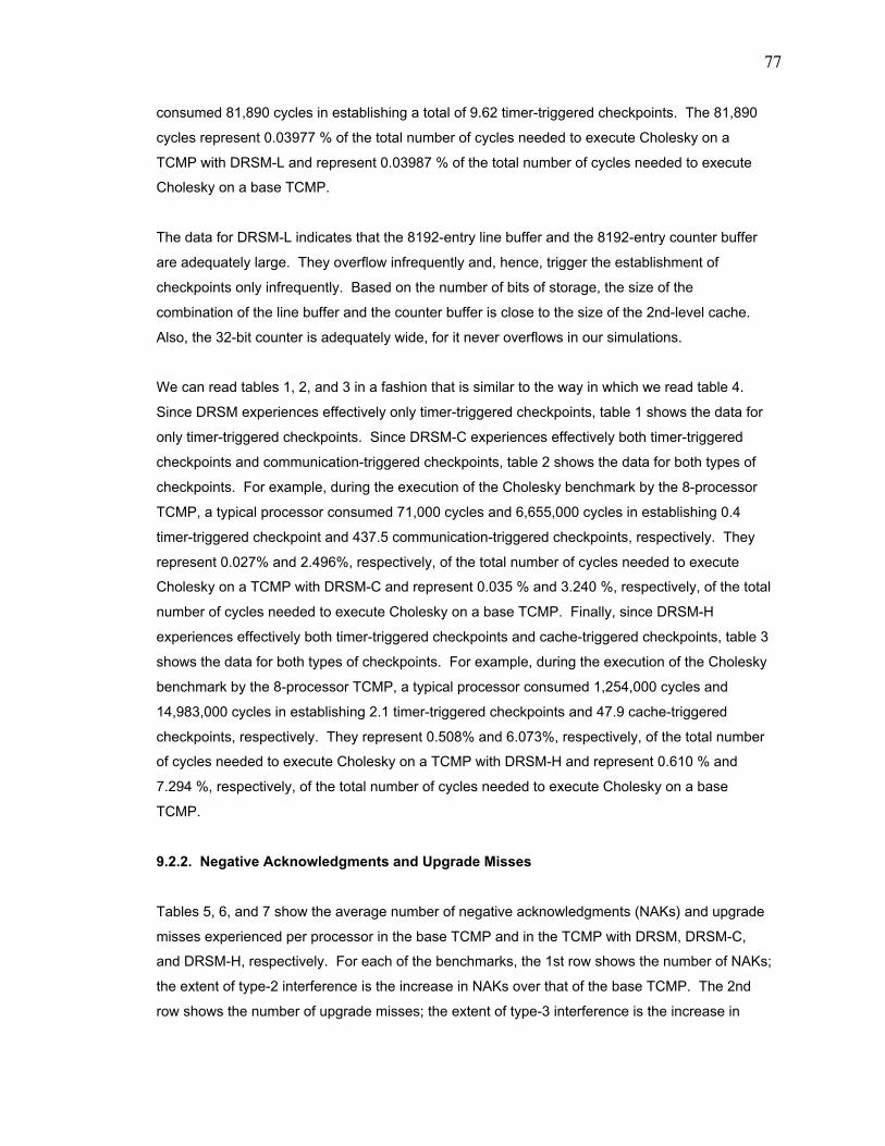
77
consumed 81,890 cycles in establishing a total of 9.62 timer-triggered checkpoints. The 81,890
cycles represent 0.03977 % of the total number of cycles needed to execute Cholesky on a
TCMP with DRSM-L and represent 0.03987 % of the total number of cycles needed to execute
Cholesky on a base TCMP.
The data for DRSM-L indicates that the 8192-entry line buffer and the 8192-entry counter buffer
are adequately large. They overflow infrequently and, hence, trigger the establishment of
checkpoints only infrequently. Based on the number of bits of storage, the size of the
combination of the line buffer and the counter buffer is close to the size of the 2nd-level cache.
Also, the 32-bit counter is adequately wide, for it never overflows in our simulations.
We can read tables 1, 2, and 3 in a fashion that is similar to the way in which we read table 4.
Since DRSM experiences effectively only timer-triggered checkpoints, table 1 shows the data for
only timer-triggered checkpoints. Since DRSM-C experiences effectively both timer-triggered
checkpoints and communication-triggered checkpoints, table 2 shows the data for both types of
checkpoints. For example, during the execution of the Cholesky benchmark by the 8-processor
TCMP, a typical processor consumed 71,000 cycles and 6,655,000 cycles in establishing 0.4
timer-triggered checkpoint and 437.5 communication-triggered checkpoints, respectively. They
represent 0.027% and 2.496%, respectively, of the total number of cycles needed to execute
Cholesky on a TCMP with DRSM-C and represent 0.035 % and 3.240 %, respectively, of the total
number of cycles needed to execute Cholesky on a base TCMP. Finally, since DRSM-H
experiences effectively both timer-triggered checkpoints and cache-triggered checkpoints, table 3
shows the data for both types of checkpoints. For example, during the execution of the Cholesky
benchmark by the 8-processor TCMP, a typical processor consumed 1,254,000 cycles and
14,983,000 cycles in establishing 2.1 timer-triggered checkpoints and 47.9 cache-triggered
checkpoints, respectively. They represent 0.508% and 6.073%, respectively, of the total number
of cycles needed to execute Cholesky on a TCMP with DRSM-H and represent 0.610 % and
7.294 %, respectively, of the total number of cycles needed to execute Cholesky on a base
TCMP.
9.2.2. Negative Acknowledgments and Upgrade Misses
Tables 5, 6, and 7 show the average number of negative acknowledgments (NAKs) and upgrade
misses experienced per processor in the base TCMP and in the TCMP with DRSM, DRSM-C,
and DRSM-H, respectively. For each of the benchmarks, the 1st row shows the number of NAKs;
the extent of type-2 interference is the increase in NAKs over that of the base TCMP. The 2nd
row shows the number of upgrade misses; the extent of type-3 interference is the increase in
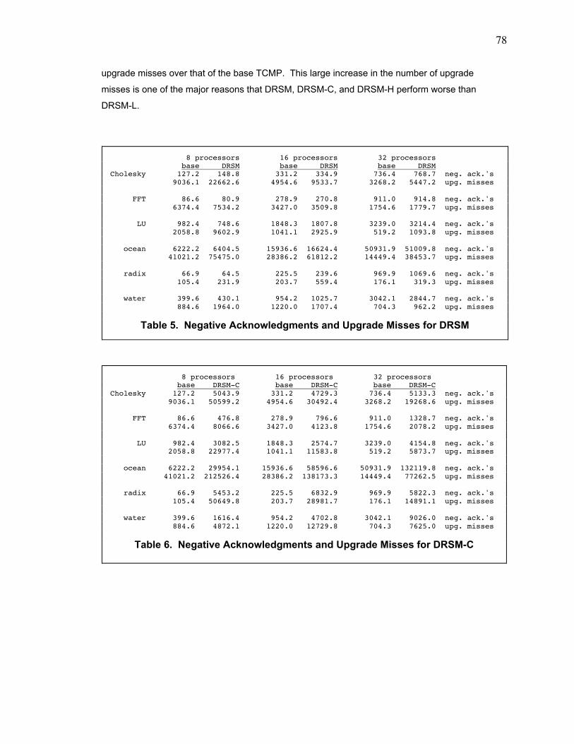
78
upgrade misses over that of the base TCMP. This large increase in the number of upgrade
misses is one of the major reasons that DRSM, DRSM-C, and DRSM-H perform worse than
DRSM-L.
8 processors 16 processors 32 processors base DRSM base DRSM base DRSMCholesky 127.2 148.8 331.2 334.9 736.4 768.7 neg. ack.'s 9036.1 22662.6 4954.6 9533.7 3268.2 5447.2 upg. misses
FFT 86.6 80.9 278.9 270.8 911.0 914.8 neg. ack.'s 6374.4 7534.2 3427.0 3509.8 1754.6 1779.7 upg. misses
LU 982.4 748.6 1848.3 1807.8 3239.0 3214.4 neg. ack.'s 2058.8 9602.9 1041.1 2925.9 519.2 1093.8 upg. misses
ocean 6222.2 6404.5 15936.6 16624.4 50931.9 51009.8 neg. ack.'s 41021.2 75475.0 28386.2 61812.2 14449.4 38453.7 upg. misses
radix 66.9 64.5 225.5 239.6 969.9 1069.6 neg. ack.'s 105.4 231.9 203.7 559.4 176.1 319.3 upg. misses
water 399.6 430.1 954.2 1025.7 3042.1 2844.7 neg. ack.'s 884.6 1964.0 1220.0 1707.4 704.3 962.2 upg. misses
Table 5. Negative Acknowledgments and Upgrade Misses for DRSM
8 processors 16 processors 32 processors base DRSM-C base DRSM-C base DRSM-CCholesky 127.2 5043.9 331.2 4729.3 736.4 5133.3 neg. ack.'s 9036.1 50599.2 4954.6 30492.4 3268.2 19268.6 upg. misses
FFT 86.6 476.8 278.9 796.6 911.0 1328.7 neg. ack.'s 6374.4 8066.6 3427.0 4123.8 1754.6 2078.2 upg. misses
LU 982.4 3082.5 1848.3 2574.7 3239.0 4154.8 neg. ack.'s 2058.8 22977.4 1041.1 11583.8 519.2 5873.7 upg. misses
ocean 6222.2 29954.1 15936.6 58596.6 50931.9 132119.8 neg. ack.'s 41021.2 212526.4 28386.2 138173.3 14449.4 77262.5 upg. misses
radix 66.9 5453.2 225.5 6832.9 969.9 5822.3 neg. ack.'s 105.4 50649.8 203.7 28981.7 176.1 14891.1 upg. misses
water 399.6 1616.4 954.2 4702.8 3042.1 9026.0 neg. ack.'s 884.6 4872.1 1220.0 12729.8 704.3 7625.0 upg. misses
Table 6. Negative Acknowledgments and Upgrade Misses for DRSM-C

79
Table 8 shows the average number of negative acknowledgments (NAKs) and upgrade misses
experienced per processor in the base TCMP and in the TCMP with DRSM-L. For each of the
benchmarks, the 1st row shows the number of NAKs; the extent of type-2 interference is the
increase in NAKs over that of the base TCMP. The 2nd row shows the number of upgrade
misses. A processor in DRSM-L does not suffer type-3 interference.
8 processors 16 processors 32 processors base DRSM-H base DRSM-H base DRSM-HCholesky 127.2 1197.4 331.2 1603.2 736.4 2537.8 neg. ack.'s 9036.1 38662.0 4954.6 21136.7 3268.2 13516.6 upg. misses
FFT 86.6 125.5 278.9 319.2 911.0 922.5 neg. ack.'s 6374.4 10040.8 3427.0 3545.7 1754.6 1766.1 upg. misses
LU 982.4 1078.6 1848.3 2235.4 3239.0 3535.5 neg. ack.'s 2058.8 9929.8 1041.1 3680.2 519.2 1197.9 upg. misses
ocean 6222.2 6940.4 15936.6 16692.9 50931.9 50795.3 neg. ack.'s 41021.2 94987.2 28386.2 73821.8 14449.4 43733.1 upg. misses
radix 66.9 158.2 225.5 311.6 969.9 1125.2 neg. ack.'s 105.4 8357.6 203.7 1878.4 176.1 375.2 upg. misses
water 399.6 657.0 954.2 1674.3 3042.1 3171.4 neg. ack.'s 884.6 2190.5 1220.0 2341.1 704.3 978.7 upg. misses
Table 7. Negative Acknowledgments and Upgrade Misses for DRSM-H
8 processors 16 processors 32 processors base DRSM-L base DRSM-L base DRSM-LCholesky 127.2 148.1 331.2 340.2 736.4 665.9 neg. ack.'s 9036.1 9078.9 4954.6 4938.4 3268.2 3285.2 upg. misses
FFT 86.6 95.2 278.9 269.0 911.0 908.4 neg. ack.'s 6374.4 6377.2 3427.0 3428.5 1754.6 1755.4 upg. misses
LU 982.4 993.4 1848.3 1915.9 3239.0 3225.6 neg. ack.'s 2058.8 2058.5 1041.1 1042.2 519.2 520.6 upg. misses
ocean 6222.2 6347.1 15936.6 16480.3 50931.9 50128.0 neg. ack.'s 41021.2 40980.4 28386.2 28430.9 14449.4 14511.8 upg. misses
radix 66.9 67.9 225.5 240.1 969.9 926.4 neg. ack.'s 105.4 107.0 203.7 209.3 176.1 178.1 upg. misses
water 399.6 440.0 954.2 1007.7 3042.1 2979.5 neg. ack.'s 884.6 888.5 1220.0 1226.8 704.3 705.8 upg. misses
Table 8. Negative Acknowledgments and Upgrade Misses for DRSM-L
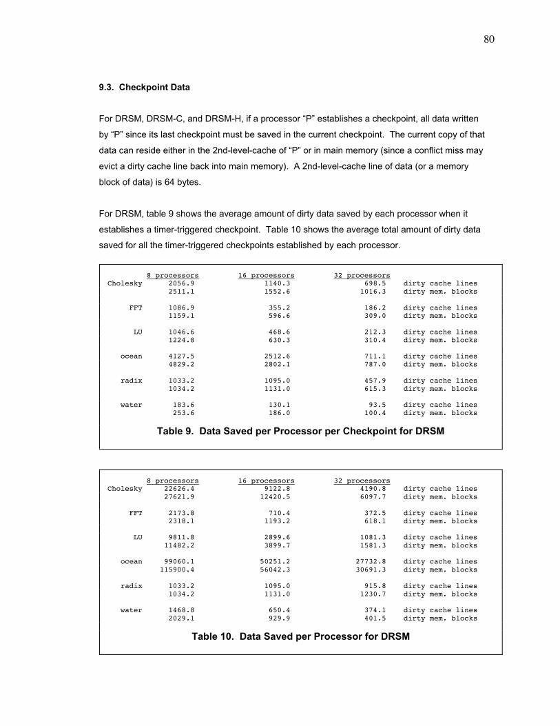
80
9.3. Checkpoint Data
For DRSM, DRSM-C, and DRSM-H, if a processor ÒPÓ establishes a checkpoint, all data written
by ÒPÓ since its last checkpoint must be saved in the current checkpoint. The current copy of that
data can reside either in the 2nd-level-cache of ÒPÓ or in main memory (since a conflict miss may
evict a dirty cache line back into main memory). A 2nd-level-cache line of data (or a memory
block of data) is 64 bytes.
For DRSM, table 9 shows the average amount of dirty data saved by each processor when it
establishes a timer-triggered checkpoint. Table 10 shows the average total amount of dirty data
saved for all the timer-triggered checkpoints established by each processor.
8 processors 16 processors 32 processorsCholesky 2056.9 1140.3 698.5 dirty cache lines 2511.1 1552.6 1016.3 dirty mem. blocks
FFT 1086.9 355.2 186.2 dirty cache lines 1159.1 596.6 309.0 dirty mem. blocks
LU 1046.6 468.6 212.3 dirty cache lines 1224.8 630.3 310.4 dirty mem. blocks
ocean 4127.5 2512.6 711.1 dirty cache lines 4829.2 2802.1 787.0 dirty mem. blocks
radix 1033.2 1095.0 457.9 dirty cache lines 1034.2 1131.0 615.3 dirty mem. blocks
water 183.6 130.1 93.5 dirty cache lines 253.6 186.0 100.4 dirty mem. blocks
Table 9. Data Saved per Processor per Checkpoint for DRSM
8 processors 16 processors 32 processorsCholesky 22626.4 9122.8 4190.8 dirty cache lines 27621.9 12420.5 6097.7 dirty mem. blocks
FFT 2173.8 710.4 372.5 dirty cache lines 2318.1 1193.2 618.1 dirty mem. blocks
LU 9811.8 2899.6 1081.3 dirty cache lines 11482.2 3899.7 1581.3 dirty mem. blocks
ocean 99060.1 50251.2 27732.8 dirty cache lines 115900.4 56042.3 30691.3 dirty mem. blocks
radix 1033.2 1095.0 915.8 dirty cache lines 1034.2 1131.0 1230.7 dirty mem. blocks
water 1468.8 650.4 374.1 dirty cache lines 2029.1 929.9 401.5 dirty mem. blocks
Table 10. Data Saved per Processor for DRSM
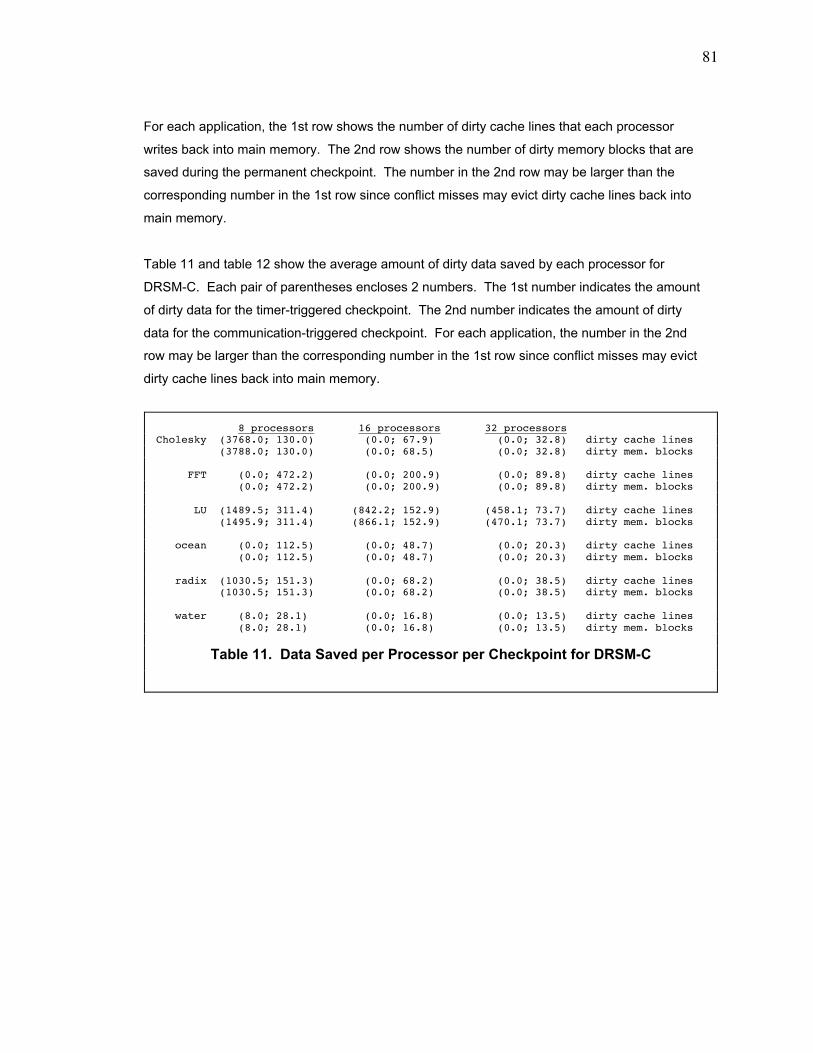
81
For each application, the 1st row shows the number of dirty cache lines that each processor
writes back into main memory. The 2nd row shows the number of dirty memory blocks that are
saved during the permanent checkpoint. The number in the 2nd row may be larger than the
corresponding number in the 1st row since conflict misses may evict dirty cache lines back into
main memory.
Table 11 and table 12 show the average amount of dirty data saved by each processor for
DRSM-C. Each pair of parentheses encloses 2 numbers. The 1st number indicates the amount
of dirty data for the timer-triggered checkpoint. The 2nd number indicates the amount of dirty
data for the communication-triggered checkpoint. For each application, the number in the 2nd
row may be larger than the corresponding number in the 1st row since conflict misses may evict
dirty cache lines back into main memory.
8 processors 16 processors 32 processorsCholesky (3768.0; 130.0) (0.0; 67.9) (0.0; 32.8) dirty cache lines (3788.0; 130.0) (0.0; 68.5) (0.0; 32.8) dirty mem. blocks
FFT (0.0; 472.2) (0.0; 200.9) (0.0; 89.8) dirty cache lines (0.0; 472.2) (0.0; 200.9) (0.0; 89.8) dirty mem. blocks
LU (1489.5; 311.4) (842.2; 152.9) (458.1; 73.7) dirty cache lines (1495.9; 311.4) (866.1; 152.9) (470.1; 73.7) dirty mem. blocks
ocean (0.0; 112.5) (0.0; 48.7) (0.0; 20.3) dirty cache lines (0.0; 112.5) (0.0; 48.7) (0.0; 20.3) dirty mem. blocks
radix (1030.5; 151.3) (0.0; 68.2) (0.0; 38.5) dirty cache lines (1030.5; 151.3) (0.0; 68.2) (0.0; 38.5) dirty mem. blocks
water (8.0; 28.1) (0.0; 16.8) (0.0; 13.5) dirty cache lines (8.0; 28.1) (0.0; 16.8) (0.0; 13.5) dirty mem. blocks
Table 11. Data Saved per Processor per Checkpoint for DRSM-C
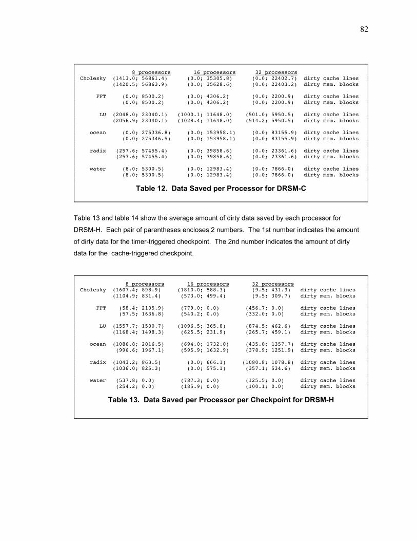
82
Table 13 and table 14 show the average amount of dirty data saved by each processor for
DRSM-H. Each pair of parentheses encloses 2 numbers. The 1st number indicates the amount
of dirty data for the timer-triggered checkpoint. The 2nd number indicates the amount of dirty
data for the cache-triggered checkpoint.
8 processors 16 processors 32 processorsCholesky (1413.0; 56861.4) (0.0; 35305.8) (0.0; 22402.7) dirty cache lines (1420.5; 56863.9) (0.0; 35628.6) (0.0; 22403.2) dirty mem. blocks
FFT (0.0; 8500.2) (0.0; 4306.2) (0.0; 2200.9) dirty cache lines (0.0; 8500.2) (0.0; 4306.2) (0.0; 2200.9) dirty mem. blocks
LU (2048.0; 23040.1) (1000.1; 11648.0) (501.0; 5950.5) dirty cache lines (2056.9; 23040.1) (1028.4; 11648.0) (514.2; 5950.5) dirty mem. blocks
ocean (0.0; 275336.8) (0.0; 153958.1) (0.0; 83155.9) dirty cache lines (0.0; 275346.5) (0.0; 153958.1) (0.0; 83155.9) dirty mem. blocks
radix (257.6; 57455.4) (0.0; 39858.6) (0.0; 23361.6) dirty cache lines (257.6; 57455.4) (0.0; 39858.6) (0.0; 23361.6) dirty mem. blocks
water (8.0; 5300.5) (0.0; 12983.4) (0.0; 7866.0) dirty cache lines (8.0; 5300.5) (0.0; 12983.4) (0.0; 7866.0) dirty mem. blocks
Table 12. Data Saved per Processor for DRSM-C
8 processors 16 processors 32 processorsCholesky (1607.4; 898.9) (1810.0; 588.3) (9.5; 431.3) dirty cache lines (1104.9; 831.4) (573.0; 499.4) (9.5; 309.7) dirty mem. blocks
FFT (58.4; 2105.9) (779.0; 0.0) (456.7; 0.0) dirty cache lines (57.5; 1636.8) (540.2; 0.0) (332.0; 0.0) dirty mem. blocks
LU (1557.7; 1500.7) (1096.5; 365.8) (874.5; 462.6) dirty cache lines (1168.4; 1498.3) (625.5; 231.9) (265.7; 459.1) dirty mem. blocks
ocean (1086.8; 2016.5) (694.0; 1732.0) (435.0; 1357.7) dirty cache lines (996.6; 1967.1) (595.9; 1632.9) (378.9; 1251.9) dirty mem. blocks
radix (1043.2; 863.5) (0.0; 666.1) (1080.8; 1078.8) dirty cache lines (1036.0; 825.3) (0.0; 575.1) (357.1; 534.6) dirty mem. blocks
water (537.8; 0.0) (787.3; 0.0) (125.5; 0.0) dirty cache lines (254.2; 0.0) (185.9; 0.0) (100.1; 0.0) dirty mem. blocks
Table 13. Data Saved per Processor per Checkpoint for DRSM-H
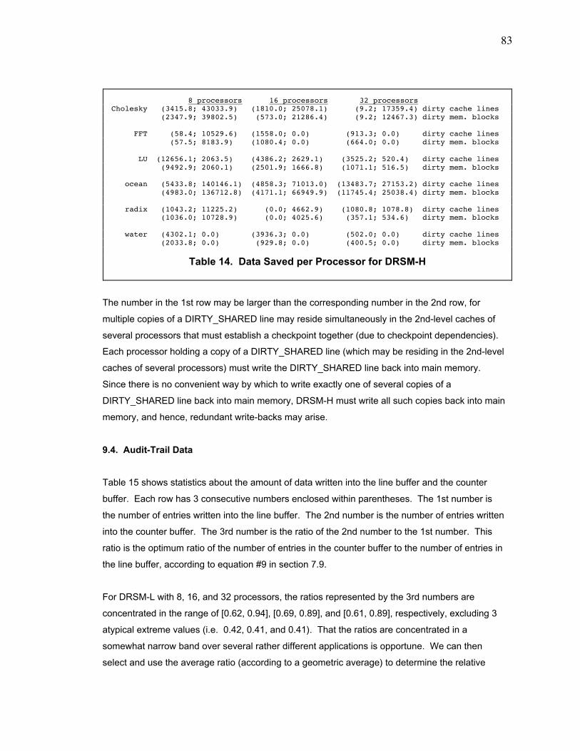
83
The number in the 1st row may be larger than the corresponding number in the 2nd row, for
multiple copies of a DIRTY_SHARED line may reside simultaneously in the 2nd-level caches of
several processors that must establish a checkpoint together (due to checkpoint dependencies).
Each processor holding a copy of a DIRTY_SHARED line (which may be residing in the 2nd-level
caches of several processors) must write the DIRTY_SHARED line back into main memory.
Since there is no convenient way by which to write exactly one of several copies of a
DIRTY_SHARED line back into main memory, DRSM-H must write all such copies back into main
memory, and hence, redundant write-backs may arise.
9.4. Audit-Trail Data
Table 15 shows statistics about the amount of data written into the line buffer and the counter
buffer. Each row has 3 consecutive numbers enclosed within parentheses. The 1st number is
the number of entries written into the line buffer. The 2nd number is the number of entries written
into the counter buffer. The 3rd number is the ratio of the 2nd number to the 1st number. This
ratio is the optimum ratio of the number of entries in the counter buffer to the number of entries in
the line buffer, according to equation #9 in section 7.9.
For DRSM-L with 8, 16, and 32 processors, the ratios represented by the 3rd numbers are
concentrated in the range of [0.62, 0.94], [0.69, 0.89], and [0.61, 0.89], respectively, excluding 3
atypical extreme values (i.e. 0.42, 0.41, and 0.41). That the ratios are concentrated in a
somewhat narrow band over several rather different applications is opportune. We can then
select and use the average ratio (according to a geometric average) to determine the relative
8 processors 16 processors 32 processorsCholesky (3415.8; 43033.9) (1810.0; 25078.1) (9.2; 17359.4) dirty cache lines (2347.9; 39802.5) (573.0; 21286.4) (9.2; 12467.3) dirty mem. blocks
FFT (58.4; 10529.6) (1558.0; 0.0) (913.3; 0.0) dirty cache lines (57.5; 8183.9) (1080.4; 0.0) (664.0; 0.0) dirty mem. blocks
LU (12656.1; 2063.5) (4386.2; 2629.1) (3525.2; 520.4) dirty cache lines (9492.9; 2060.1) (2501.9; 1666.8) (1071.1; 516.5) dirty mem. blocks
ocean (5433.8; 140146.1) (4858.3; 71013.0) (13483.7; 27153.2) dirty cache lines (4983.0; 136712.8) (4171.1; 66949.9) (11745.4; 25038.4) dirty mem. blocks
radix (1043.2; 11225.2) (0.0; 4662.9) (1080.8; 1078.8) dirty cache lines (1036.0; 10728.9) (0.0; 4025.6) (357.1; 534.6) dirty mem. blocks
water (4302.1; 0.0) (3936.3; 0.0) (502.0; 0.0) dirty cache lines (2033.8; 0.0) (929.8; 0.0) (400.5; 0.0) dirty mem. blocks
Table 14. Data Saved per Processor for DRSM-H
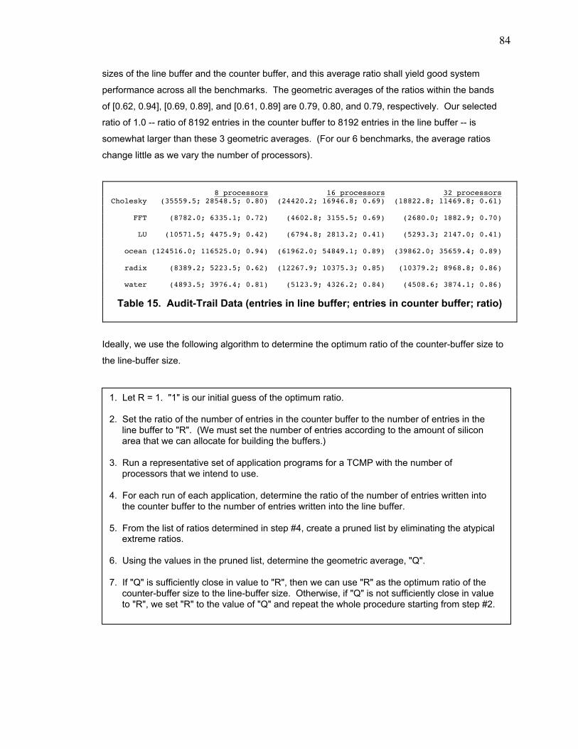
84
sizes of the line buffer and the counter buffer, and this average ratio shall yield good system
performance across all the benchmarks. The geometric averages of the ratios within the bands
of [0.62, 0.94], [0.69, 0.89], and [0.61, 0.89] are 0.79, 0.80, and 0.79, respectively. Our selected
ratio of 1.0 -- ratio of 8192 entries in the counter buffer to 8192 entries in the line buffer -- is
somewhat larger than these 3 geometric averages. (For our 6 benchmarks, the average ratios
change little as we vary the number of processors).
Ideally, we use the following algorithm to determine the optimum ratio of the counter-buffer size to
the line-buffer size.
8 processors 16 processors 32 processorsCholesky (35559.5; 28548.5; 0.80) (24420.2; 16946.8; 0.69) (18822.8; 11469.8; 0.61)
FFT (8782.0; 6335.1; 0.72) (4602.8; 3155.5; 0.69) (2680.0; 1882.9; 0.70)
LU (10571.5; 4475.9; 0.42) (6794.8; 2813.2; 0.41) (5293.3; 2147.0; 0.41)
ocean (124516.0; 116525.0; 0.94) (61962.0; 54849.1; 0.89) (39862.0; 35659.4; 0.89)
radix (8389.2; 5223.5; 0.62) (12267.9; 10375.3; 0.85) (10379.2; 8968.8; 0.86)
water (4893.5; 3976.4; 0.81) (5123.9; 4326.2; 0.84) (4508.6; 3874.1; 0.86)
Table 15. Audit-Trail Data (entries in line buffer; entries in counter buffer; ratio)
1. Let R = 1. "1" is our initial guess of the optimum ratio.
2. Set the ratio of the number of entries in the counter buffer to the number of entries in theline buffer to "R". (We must set the number of entries according to the amount of siliconarea that we can allocate for building the buffers.)
3. Run a representative set of application programs for a TCMP with the number ofprocessors that we intend to use.
4. For each run of each application, determine the ratio of the number of entries written intothe counter buffer to the number of entries written into the line buffer.
5. From the list of ratios determined in step #4, create a pruned list by eliminating the atypicalextreme ratios.
6. Using the values in the pruned list, determine the geometric average, "Q".
7. If "Q" is sufficiently close in value to "R", then we can use "R" as the optimum ratio of thecounter-buffer size to the line-buffer size. Otherwise, if "Q" is not sufficiently close in valueto "R", we set "R" to the value of "Q" and repeat the whole procedure starting from step #2.
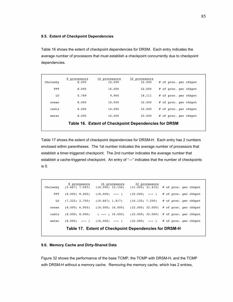
85
9.5. Extent of Checkpoint Dependencies
Table 16 shows the extent of checkpoint dependencies for DRSM. Each entry indicates the
average number of processors that must establish a checkpoint concurrently due to checkpoint
dependencies.
Table 17 shows the extent of checkpoint dependencies for DRSM-H. Each entry has 2 numbers
enclosed within parentheses. The 1st number indicates the average number of processors that
establish a timer-triggered checkpoint. The 2nd number indicates the average number that
establish a cache-triggered checkpoint. An entry of Ò---Ò indicates that the number of checkpoints
is 0.
9.6. Memory Cache and Dirty-Shared Data
Figure 32 shows the performance of the base TCMP, the TCMP with DRSM-H, and the TCMP
with DRSM-H without a memory cache. Removing the memory cache, which has 2 entries,
8 processors 16 processors 32 processorsCholesky 8.000 16.000 32.000 # of proc. per chkpnt
FFT 8.000 16.000 32.000 # of proc. per chkpnt
LU 5.769 9.900 18.111 # of proc. per chkpnt
ocean 8.000 16.000 32.000 # of proc. per chkpnt
radix 8.000 16.000 32.000 # of proc. per chkpnt
water 8.000 16.000 32.000 # of proc. per chkpnt
Table 16. Extent of Checkpoint Dependencies for DRSM
8 processors 16 processors 32 processorsCholesky (5.667; 7.093) (16.000; 15.156) (31.000; 31.415) # of proc. per chkpnt
FFT (8.000; 8.000) (16.000; --- ) (32.000; --- ) # of proc. per chkpnt
LU (7.222; 2.750) (10.667; 1.917) (16.125; 7.200) # of proc. per chkpnt
ocean (8.000; 6.950) (16.000; 16.000) (32.000; 32.000) # of proc. per chkpnt
radix (8.000; 8.000) ( --- ; 16.000) (32.000; 32.000) # of proc. per chkpnt
water (8.000; --- ) (16.000; --- ) (32.000; --- ) # of proc. per chkpnt
Table 17. Extent of Checkpoint Dependencies for DRSM-H
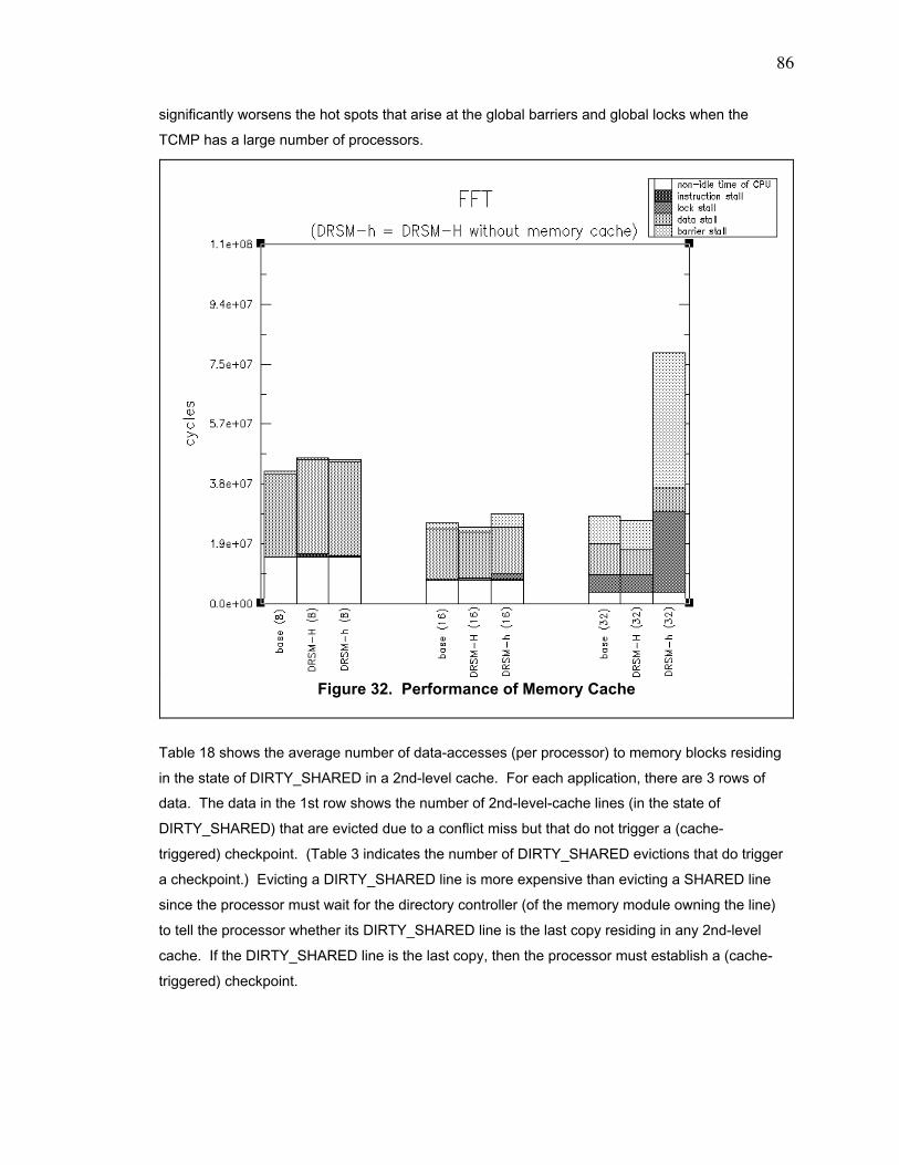
86
significantly worsens the hot spots that arise at the global barriers and global locks when the
TCMP has a large number of processors.
Table 18 shows the average number of data-accesses (per processor) to memory blocks residing
in the state of DIRTY_SHARED in a 2nd-level cache. For each application, there are 3 rows of
data. The data in the 1st row shows the number of 2nd-level-cache lines (in the state of
DIRTY_SHARED) that are evicted due to a conflict miss but that do not trigger a (cache-
triggered) checkpoint. (Table 3 indicates the number of DIRTY_SHARED evictions that do trigger
a checkpoint.) Evicting a DIRTY_SHARED line is more expensive than evicting a SHARED line
since the processor must wait for the directory controller (of the memory module owning the line)
to tell the processor whether its DIRTY_SHARED line is the last copy residing in any 2nd-level
cache. If the DIRTY_SHARED line is the last copy, then the processor must establish a (cache-
triggered) checkpoint.
Figure 32. Performance of Memory Cache
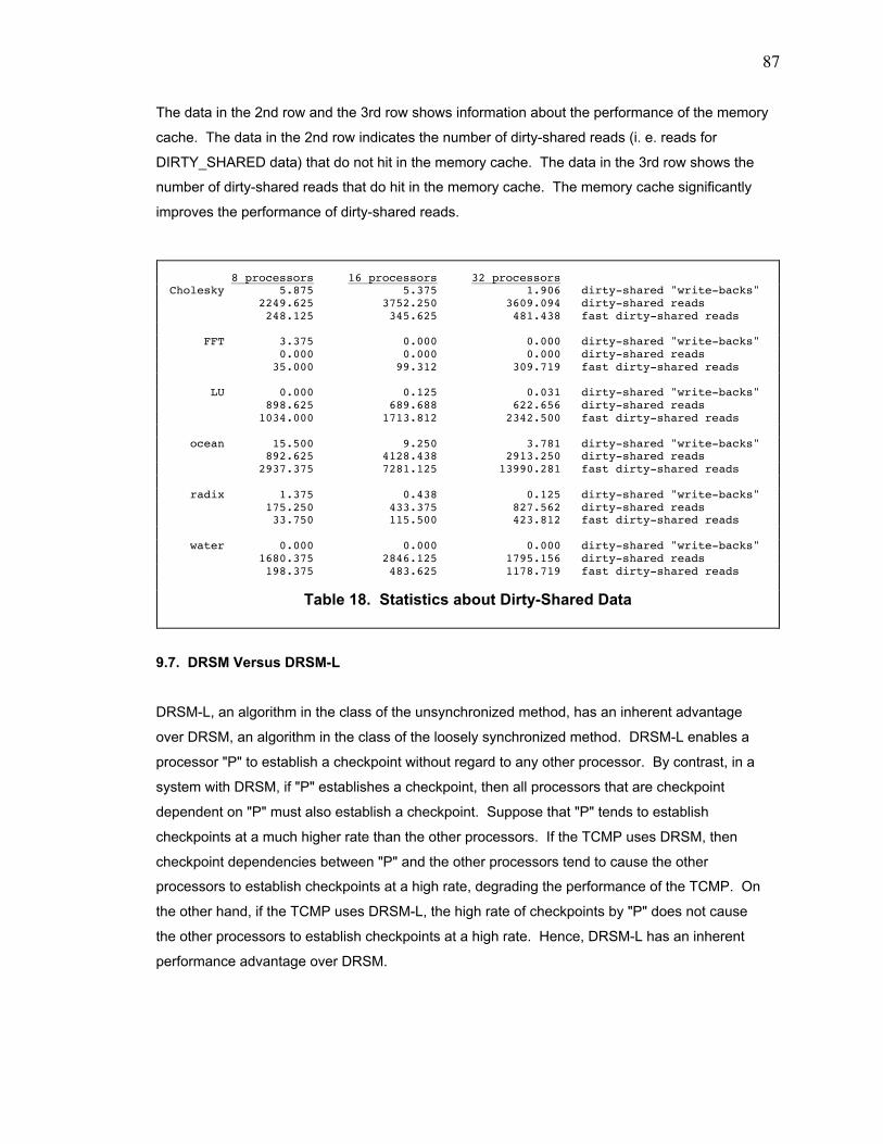
87
The data in the 2nd row and the 3rd row shows information about the performance of the memory
cache. The data in the 2nd row indicates the number of dirty-shared reads (i. e. reads for
DIRTY_SHARED data) that do not hit in the memory cache. The data in the 3rd row shows the
number of dirty-shared reads that do hit in the memory cache. The memory cache significantly
improves the performance of dirty-shared reads.
9.7. DRSM Versus DRSM-L
DRSM-L, an algorithm in the class of the unsynchronized method, has an inherent advantage
over DRSM, an algorithm in the class of the loosely synchronized method. DRSM-L enables a
processor "P" to establish a checkpoint without regard to any other processor. By contrast, in a
system with DRSM, if "P" establishes a checkpoint, then all processors that are checkpoint
dependent on "P" must also establish a checkpoint. Suppose that "P" tends to establish
checkpoints at a much higher rate than the other processors. If the TCMP uses DRSM, then
checkpoint dependencies between "P" and the other processors tend to cause the other
processors to establish checkpoints at a high rate, degrading the performance of the TCMP. On
the other hand, if the TCMP uses DRSM-L, the high rate of checkpoints by "P" does not cause
the other processors to establish checkpoints at a high rate. Hence, DRSM-L has an inherent
performance advantage over DRSM.
8 processors 16 processors 32 processorsCholesky 5.875 5.375 1.906 dirty-shared "write-backs" 2249.625 3752.250 3609.094 dirty-shared reads 248.125 345.625 481.438 fast dirty-shared reads
FFT 3.375 0.000 0.000 dirty-shared "write-backs" 0.000 0.000 0.000 dirty-shared reads 35.000 99.312 309.719 fast dirty-shared reads
LU 0.000 0.125 0.031 dirty-shared "write-backs" 898.625 689.688 622.656 dirty-shared reads 1034.000 1713.812 2342.500 fast dirty-shared reads
ocean 15.500 9.250 3.781 dirty-shared "write-backs" 892.625 4128.438 2913.250 dirty-shared reads 2937.375 7281.125 13990.281 fast dirty-shared reads
radix 1.375 0.438 0.125 dirty-shared "write-backs" 175.250 433.375 827.562 dirty-shared reads 33.750 115.500 423.812 fast dirty-shared reads
water 0.000 0.000 0.000 dirty-shared "write-backs" 1680.375 2846.125 1795.156 dirty-shared reads 198.375 483.625 1178.719 fast dirty-shared reads
Table 18. Statistics about Dirty-Shared Data
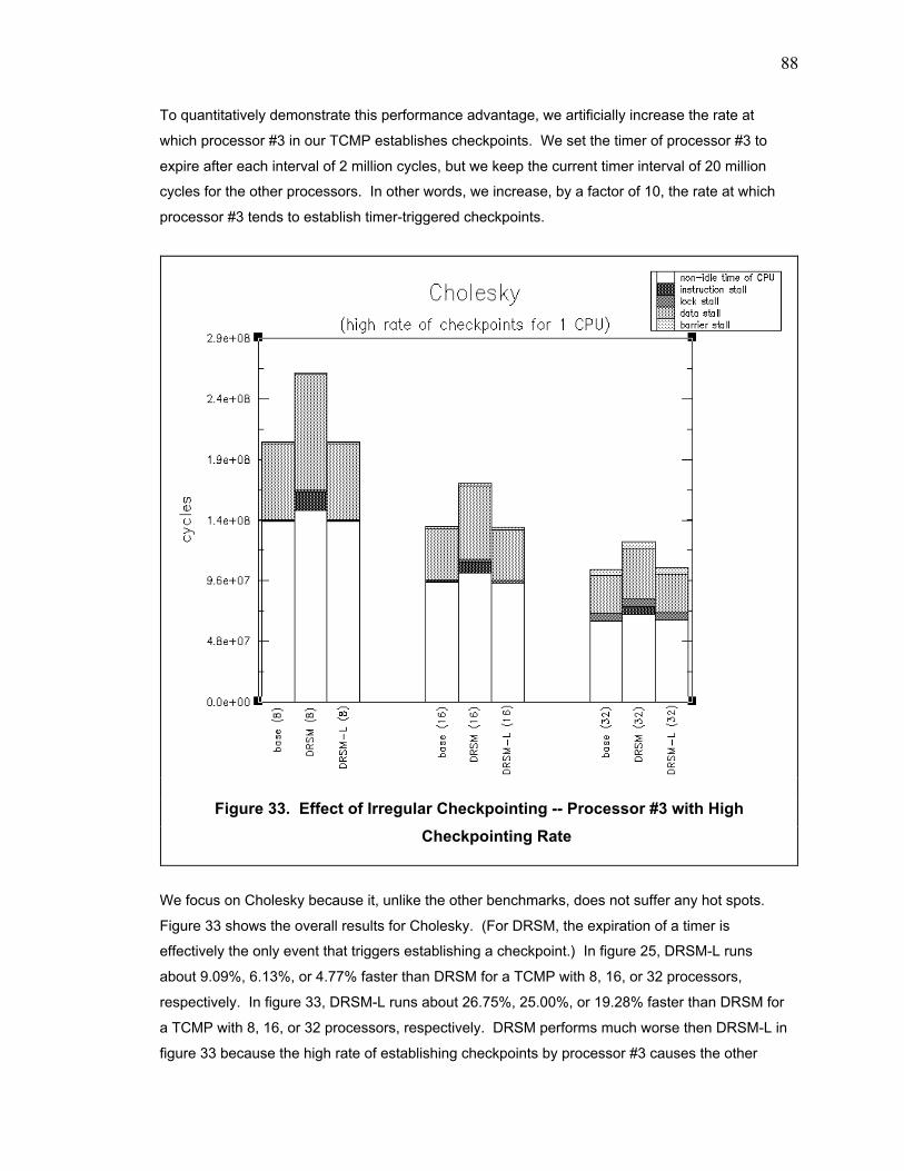
88
To quantitatively demonstrate this performance advantage, we artificially increase the rate at
which processor #3 in our TCMP establishes checkpoints. We set the timer of processor #3 to
expire after each interval of 2 million cycles, but we keep the current timer interval of 20 million
cycles for the other processors. In other words, we increase, by a factor of 10, the rate at which
processor #3 tends to establish timer-triggered checkpoints.
We focus on Cholesky because it, unlike the other benchmarks, does not suffer any hot spots.
Figure 33 shows the overall results for Cholesky. (For DRSM, the expiration of a timer is
effectively the only event that triggers establishing a checkpoint.) In figure 25, DRSM-L runs
about 9.09%, 6.13%, or 4.77% faster than DRSM for a TCMP with 8, 16, or 32 processors,
respectively. In figure 33, DRSM-L runs about 26.75%, 25.00%, or 19.28% faster than DRSM for
a TCMP with 8, 16, or 32 processors, respectively. DRSM performs much worse then DRSM-L in
figure 33 because the high rate of establishing checkpoints by processor #3 causes the other
Figure 33. Effect of Irregular Checkpointing -- Processor #3 with High
Checkpointing Rate
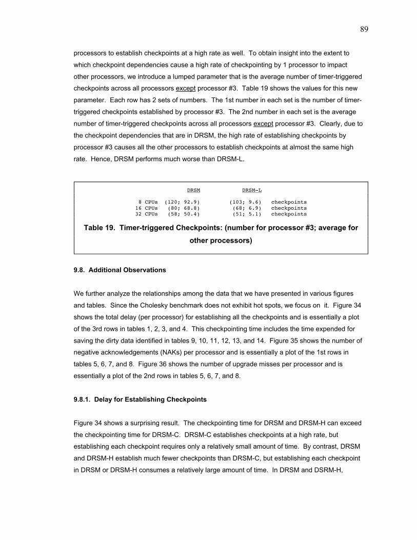
89
processors to establish checkpoints at a high rate as well. To obtain insight into the extent to
which checkpoint dependencies cause a high rate of checkpointing by 1 processor to impact
other processors, we introduce a lumped parameter that is the average number of timer-triggered
checkpoints across all processors except processor #3. Table 19 shows the values for this new
parameter. Each row has 2 sets of numbers. The 1st number in each set is the number of timer-
triggered checkpoints established by processor #3. The 2nd number in each set is the average
number of timer-triggered checkpoints across all processors except processor #3. Clearly, due to
the checkpoint dependencies that are in DRSM, the high rate of establishing checkpoints by
processor #3 causes all the other processors to establish checkpoints at almost the same high
rate. Hence, DRSM performs much worse than DRSM-L.
9.8. Additional Observations
We further analyze the relationships among the data that we have presented in various figures
and tables. Since the Cholesky benchmark does not exhibit hot spots, we focus on it. Figure 34
shows the total delay (per processor) for establishing all the checkpoints and is essentially a plot
of the 3rd rows in tables 1, 2, 3, and 4. This checkpointing time includes the time expended for
saving the dirty data identified in tables 9, 10, 11, 12, 13, and 14. Figure 35 shows the number of
negative acknowledgements (NAKs) per processor and is essentially a plot of the 1st rows in
tables 5, 6, 7, and 8. Figure 36 shows the number of upgrade misses per processor and is
essentially a plot of the 2nd rows in tables 5, 6, 7, and 8.
9.8.1. Delay for Establishing Checkpoints
Figure 34 shows a surprising result. The checkpointing time for DRSM and DRSM-H can exceed
the checkpointing time for DRSM-C. DRSM-C establishes checkpoints at a high rate, but
establishing each checkpoint requires only a relatively small amount of time. By contrast, DRSM
and DRSM-H establish much fewer checkpoints than DRSM-C, but establishing each checkpoint
in DRSM or DRSM-H consumes a relatively large amount of time. In DRSM and DSRM-H,
DRSM DRSM-L
8 CPUs (120; 92.9) (103; 9.6) checkpoints 16 CPUs (80; 68.8) (68; 6.9) checkpoints 32 CPUs (58; 50.4) (51; 5.1) checkpoints
Table 19. Timer-triggered Checkpoints: (number for processor #3; average for
other processors)
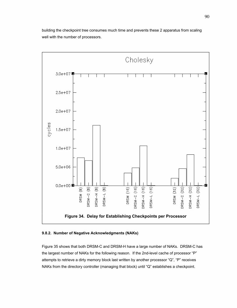
90
building the checkpoint tree consumes much time and prevents these 2 apparatus from scaling
well with the number of processors.
9.8.2. Number of Negative Acknowledgments (NAKs)
Figure 35 shows that both DRSM-C and DRSM-H have a large number of NAKs. DRSM-C has
the largest number of NAKs for the following reason. If the 2nd-level cache of processor ÒPÓ
attempts to retrieve a dirty memory block last written by another processor ÒQÓ, ÒPÓ receives
NAKs from the directory controller (managing that block) until ÒQÓ establishes a checkpoint.
Figure 34. Delay for Establishing Checkpoints per Processor
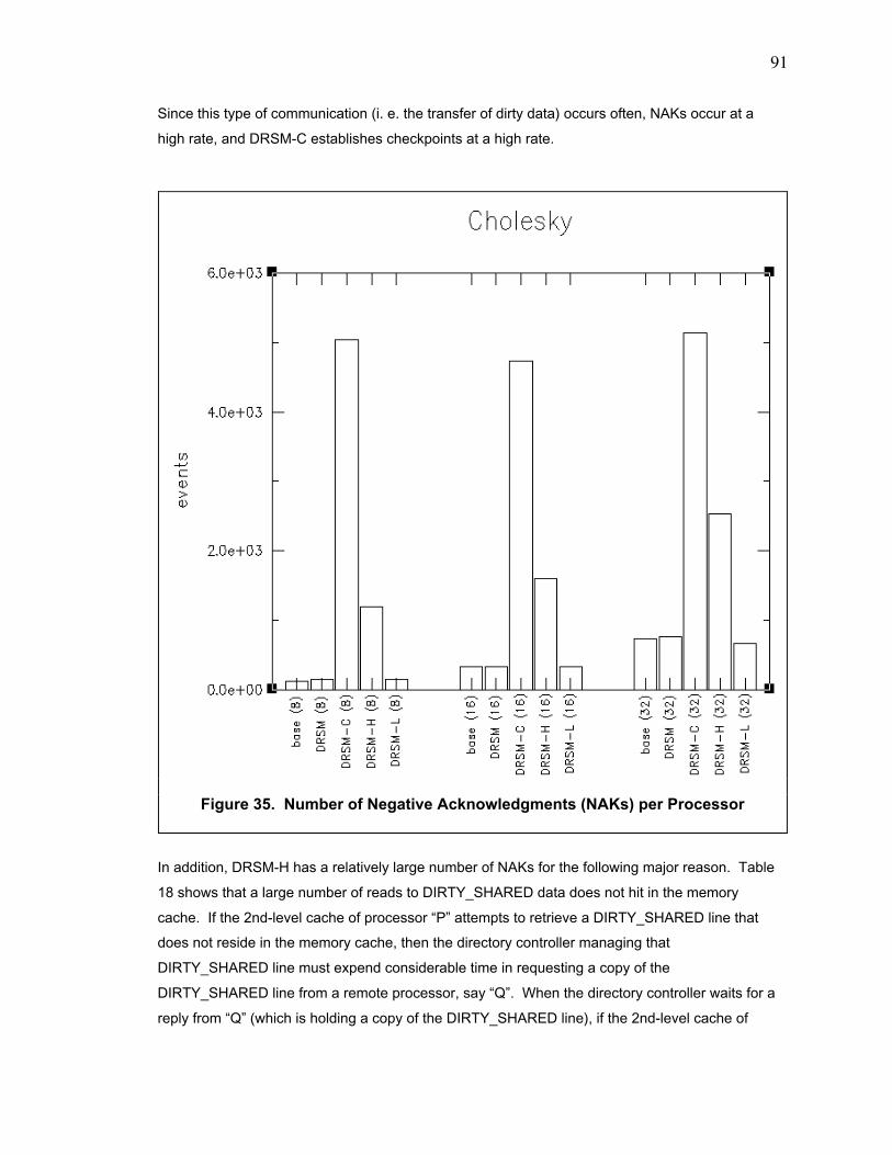
91
Since this type of communication (i. e. the transfer of dirty data) occurs often, NAKs occur at a
high rate, and DRSM-C establishes checkpoints at a high rate.
In addition, DRSM-H has a relatively large number of NAKs for the following major reason. Table
18 shows that a large number of reads to DIRTY_SHARED data does not hit in the memory
cache. If the 2nd-level cache of processor ÒPÓ attempts to retrieve a DIRTY_SHARED line that
does not reside in the memory cache, then the directory controller managing that
DIRTY_SHARED line must expend considerable time in requesting a copy of the
DIRTY_SHARED line from a remote processor, say ÒQÓ. When the directory controller waits for a
reply from ÒQÓ (which is holding a copy of the DIRTY_SHARED line), if the 2nd-level cache of
Figure 35. Number of Negative Acknowledgments (NAKs) per Processor
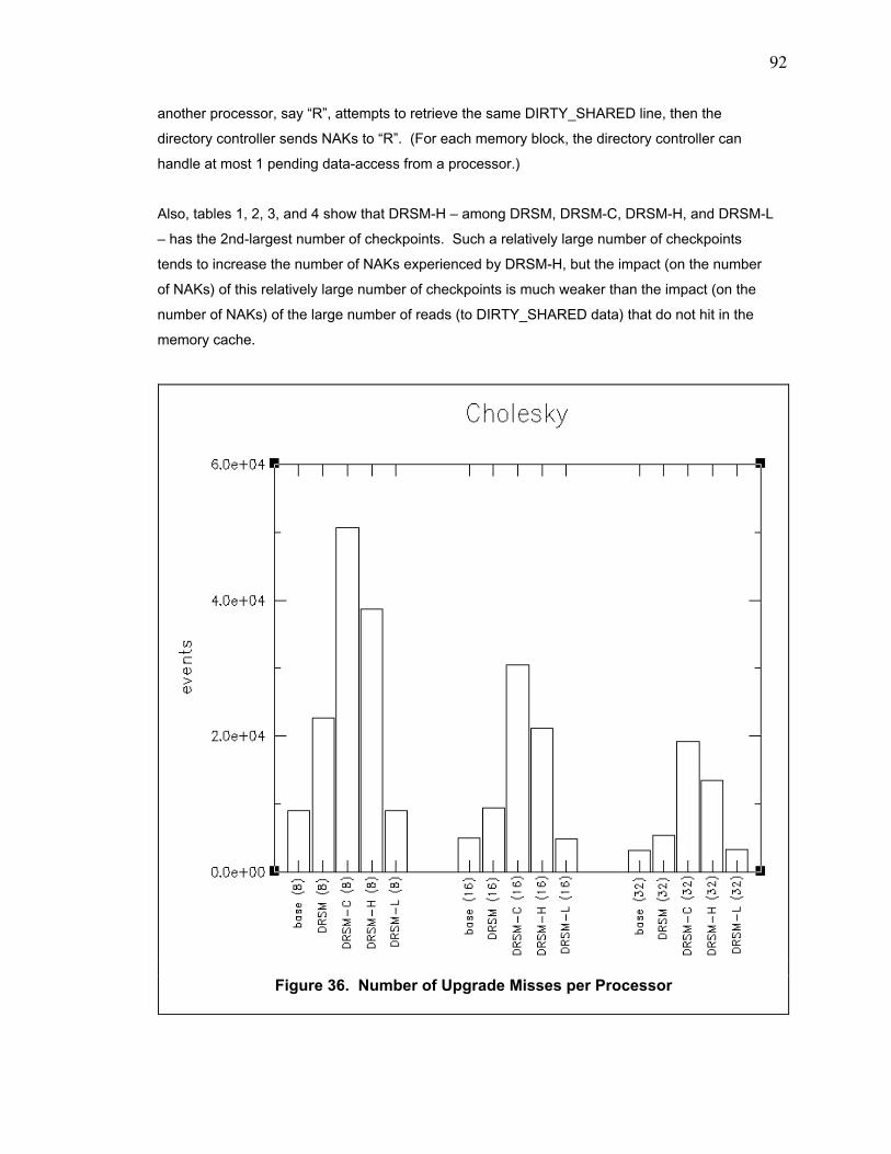
92
another processor, say ÒRÓ, attempts to retrieve the same DIRTY_SHARED line, then the
directory controller sends NAKs to ÒRÓ. (For each memory block, the directory controller can
handle at most 1 pending data-access from a processor.)
Also, tables 1, 2, 3, and 4 show that DRSM-H Ð among DRSM, DRSM-C, DRSM-H, and DRSM-L
Ð has the 2nd-largest number of checkpoints. Such a relatively large number of checkpoints
tends to increase the number of NAKs experienced by DRSM-H, but the impact (on the number
of NAKs) of this relatively large number of checkpoints is much weaker than the impact (on the
number of NAKs) of the large number of reads (to DIRTY_SHARED data) that do not hit in the
memory cache.
Figure 36. Number of Upgrade Misses per Processor
93
9.8.3. Number of Upgrade Misses
Figure 36 most closely resembles figure 25 in terms of the relative heights of the bars in the
graphs. Since figure 36 is the graph of the number of upgrade misses, this resemblance proves
that the number of upgrade misses is the principal factor differentiating the performance of
DRSM, DRSM-C, DSRM-H, and DSRM-L for a TCMP with our parameters. (See section 8.1. for
the parameters.)
9.9. High Rate of Checkpoints for All Processors
In appendix B, we present the performance data for DRSM, DRSM-C, DRSM-H, and DRSM-L for
a timer that expires per 2,000,000 cycles. DRSM and DRSM-H perform notably worse than they
perform for a timer that expires per 20,000,000 cycles. The performance of DRSM-C and DRSM-
L remains the same.
For DRSM-L, when the timer interval decreases from 20,000,000 cycles to 2,000,000 cycles, the
rate at which each processor establishes checkpoints increases by a factor of 10. In fact, timer-
triggered checkpoints become the only type of checkpoints experienced by all the processors. A
timer-triggered checkpoint occurs well before either the line buffer or the counter buffer has a
chance to overflow. If we assume that the rate (i. e. entries per unit time) at which each buffer
fills is constant, then we can reduce the size of each buffer by a factor of 10 (i. e. the factor by
which the rate of checkpoints increases) without affecting the performance of the processor.
Since the memory system works with powers of 2, we would reduce the size of each buffer (by a
factor of 8) from 8192 entries to 1024 entries.
94
Chapter 10. Conclusions
10.1. DRSM-C
Among the 4 apparatus and algorithms for establishing checkpoints, DRSM-C generally performs
worst. The communication delivering dirty data from either a processor or a memory module to
another processor causes a typical processor to establish checkpoints at a high rate. In order to
establish many checkpoints, the typical processor frequently flushes its 2nd-level cache and,
hence, suffers many upgrade misses after each checkpoint.
10.2. DRSM and DRSM-H
Both DRSM and DRSM-H perform better than DRSM-C since they have a much lower rate of
establishing checkpoints. They suffer less upgrade misses than DRSM-C. Nonetheless, these
algorithms in the class of the loosely synchronized method exhibit a type-1 interference (in
reference to section 9.2) that is approximately as worse as the type-1 interference exhibited by
DRSM-C. The reason is that both DRSM and DRSM-H spend much time in establishing each
checkpoint. For example, they spend much time in creating the checkpoint tree; in particular, the
processors in DRSM-H must complete their permanent checkpoint before the memory modules
may complete their permanent checkpoint. Hence, the algorithms in the class of the loosely
synchronized method scale poorly. Also, DRSM-H performs worse than DRSM because the set
associativity of the very large 2nd-level cache is not large enough to eliminate all conflict misses.
As a result, a small number of the conflict misses ejects the last copy of a dirty (i. e.
DIRTY_SHARED or EXCLUSIVE) 2nd-level-cache line and triggers the establishment of a
checkpoint. DRSM-H ends up in establishing more checkpoints than DRSM.
10.3. DRSM-L
Among the 4 apparatus and algorithms for establishing checkpoints, DRSM-L performs best.
Specifically, DRSM-L performs significantly better than DRSM when 1 processor tends to
establish checkpoints at a high rate. (See section 9.7.) Such a scenario can arise when
applications are structured in the following way. One processor, "P", in the TCMP performs I/O (i.
95
e. communication) with the environment outside of the TCMP. Each of the other processors in
the TCMP performs the core computation of the application and periodically sends results to "P".
"P" sends many messages (containing those results) to the environment outside of the TCMP
and, hence, must establish (external-communication-triggered) checkpoints frequently. When "P"
does so, it will not interfere with the core computation being performed by the other processors Ð-
if the TCMP uses DRSM-L.
This good performance of DRSM-L depends on it having a line buffer and a counter buffer that
are large enough to effectively minimize line-buffer-triggered checkpoints and counter-buffer-
triggered checkpoints. Our line buffer with 8192 entries and our counter buffer with 8192 entries
are adequately large; each buffer infrequently overflows and, hence, infrequently triggers the
establishment of a checkpoint. The number of bits of storage used by the combination of both the
8192-entry line buffer and the 8192-entry counter buffer is approximately the same number of bits
of storage used by our 2nd-level cache. Hence, the sizes of the line buffer and the counter buffer
are reasonable, and they can fit comfortably within the memory module.
The good performance of DRSM-L also depends on it having a counter (in each 2nd-level-cache
line) that is wide enough to effectively minimize overflow. Our counter with 32 bits is adequately
wide since the 32-bit counters never overflow in our simulations.
Overall, we conclude that DRSM-L is a good checkpointing apparatus and algorithm for TCMPs.
DRSM-L is the first algorithm in the class of the unsynchronized method for a TCMP. Unlike
current algorithms, DRSM-L allows independent establishment of a checkpoint and independent
roll-back from a fault and, hence, is much more scalable than DRSM, DRSM-C, or DRSM-H.
Also, DRSM-L is substantially cheaper to implement than the other apparatus for checkpointing.
In particular, DRSM-L requires only a single bank of memory, but RSM [2], DRSM, and DRSM-C
require 2 banks of memory.
10.4. Future Work
We suggest some avenues of future research that extends our work.
10.4.1. Simulation
In this dissertation, we focused on the relative performance of DRSM, DRSM-C, DRSM-H, and
DSRM-L on a TCMP. To obtain precise timing information about their absolute performance, we
should evaluate them by simulating a memory system that is more sophisticated than the one that

96
we used. Specifically, the memory system should have a write buffer between the 1st-level
cache and the 2nd-level cache and should use weak consistency (like release consistency) for
the memory model.
10.4.2. Proof of Concept
Even with a sophisticated memory system, the simulations will confirm what we conclude in this
dissertation. Namely, the DRSM-L performs best. In order to validate the simulations, we should
actually build a computer with DRSM-L; building a 4-processor system with DRSM-L should
suffice for a proof of concept. The hardware of DRSM-L requires a new 2nd-level cache, a line
buffer, a counter buffer, and a checkpoint-state buffer. To simplify matters, we should focus on
recovering from only transient faults.
In addition, we must expend considerable effort to create the new software supporting DRSM-L.
To simplify matters, we should omit the virtual-machine monitor but should select a simple
operating system (like Linux) into which we code support for DRSM-L. In order to support
establishing a checkpoint, we must modify both the code handling context switches and the code
handling interrupts to invoke the establishment of a checkpoint. In order to support rolling back to
the last checkpoint to recover from a fault, we must add a new section of code to the operating
system. Writing this new section of code to support the recovery process is probably the most
complicated aspect of building our fault-tolerant computer system because we (in designing the
DRSM-L) simplified the checkpointing process by moving its complexity into the recovery
process.
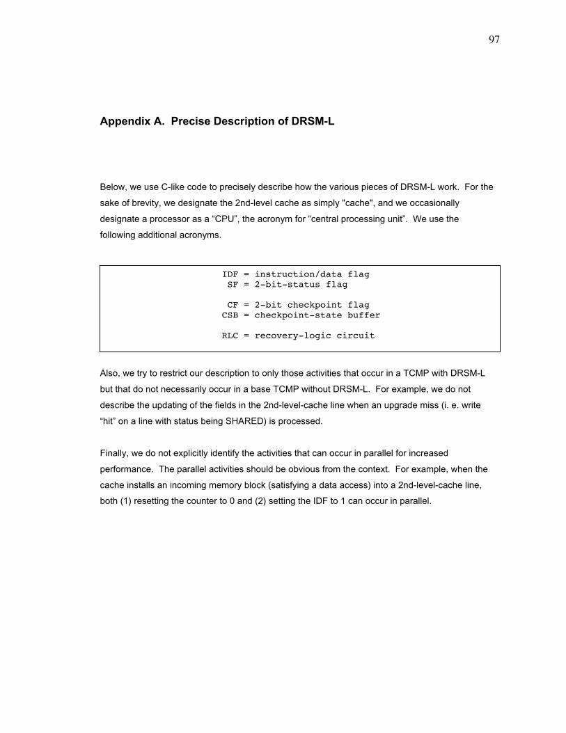
97
Appendix A. Precise Description of DRSM-L
Below, we use C-like code to precisely describe how the various pieces of DRSM-L work. For the
sake of brevity, we designate the 2nd-level cache as simply "cache", and we occasionally
designate a processor as a ÒCPUÓ, the acronym for Òcentral processing unitÓ. We use the
following additional acronyms.
Also, we try to restrict our description to only those activities that occur in a TCMP with DRSM-L
but that do not necessarily occur in a base TCMP without DRSM-L. For example, we do not
describe the updating of the fields in the 2nd-level-cache line when an upgrade miss (i. e. write
ÒhitÓ on a line with status being SHARED) is processed.
Finally, we do not explicitly identify the activities that can occur in parallel for increased
performance. The parallel activities should be obvious from the context. For example, when the
cache installs an incoming memory block (satisfying a data access) into a 2nd-level-cache line,
both (1) resetting the counter to 0 and (2) setting the IDF to 1 can occur in parallel.
IDF = instruction/data flag SF = 2-bit-status flag
CF = 2-bit checkpoint flag CSB = checkpoint-state buffer
RLC = recovery-logic circuit
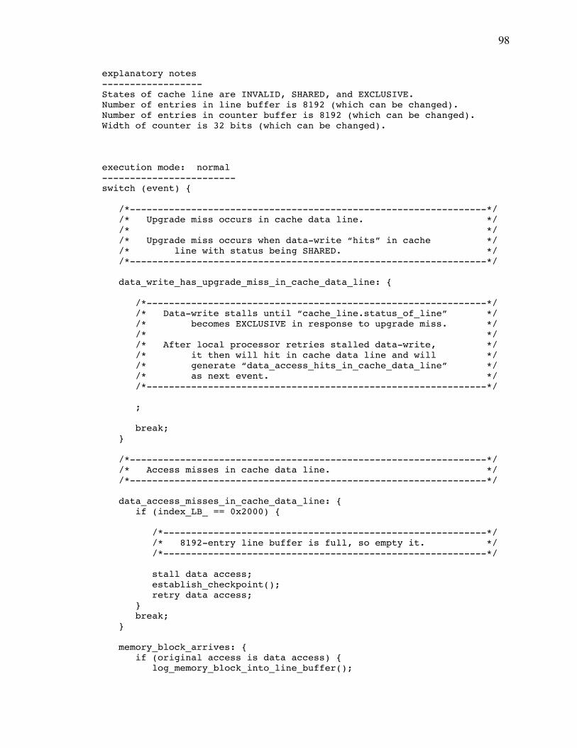
98
explanatory notes------------------States of cache line are INVALID, SHARED, and EXCLUSIVE.Number of entries in line buffer is 8192 (which can be changed).Number of entries in counter buffer is 8192 (which can be changed).Width of counter is 32 bits (which can be changed).
execution mode: normal------------------------switch (event) {
/*----------------------------------------------------------------*/ /* Upgrade miss occurs in cache data line. */ /* */ /* Upgrade miss occurs when data-write ÒhitsÓ in cache */ /* line with status being SHARED. */ /*----------------------------------------------------------------*/
data_write_has_upgrade_miss_in_cache_data_line: {
/*-------------------------------------------------------------*/ /* Data-write stalls until Òcache_line.status_of_lineÓ */ /* becomes EXCLUSIVE in response to upgrade miss. */ /* */ /* After local processor retries stalled data-write, */ /* it then will hit in cache data line and will */ /* generate Òdata_access_hits_in_cache_data_lineÓ */ /* as next event. */ /*-------------------------------------------------------------*/
;
break; }
/*----------------------------------------------------------------*/ /* Access misses in cache data line. */ /*----------------------------------------------------------------*/
data_access_misses_in_cache_data_line: { if (index_LB_ == 0x2000) {
/*----------------------------------------------------------*/ /* 8192-entry line buffer is full, so empty it. */ /*----------------------------------------------------------*/
stall data access; establish_checkpoint(); retry data access; } break; }
memory_block_arrives: { if (original access is data access) { log_memory_block_into_line_buffer();
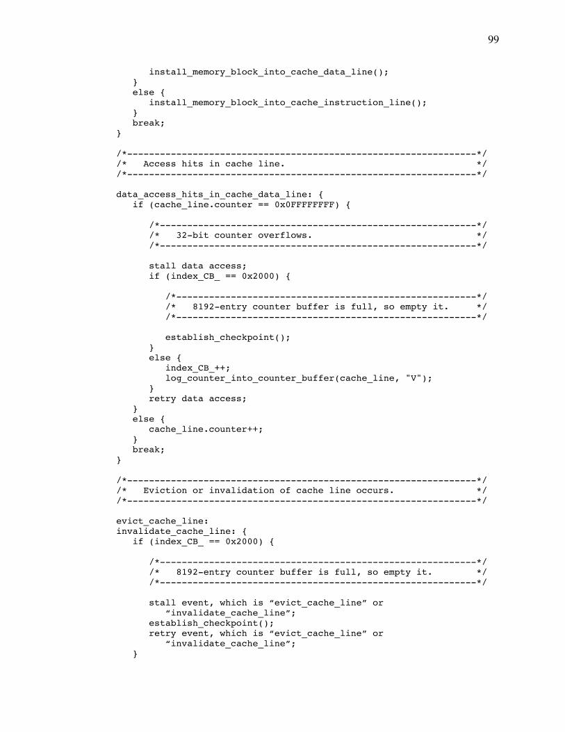
99
install_memory_block_into_cache_data_line(); } else { install_memory_block_into_cache_instruction_line(); } break; }
/*----------------------------------------------------------------*/ /* Access hits in cache line. */ /*----------------------------------------------------------------*/
data_access_hits_in_cache_data_line: { if (cache_line.counter == 0x0FFFFFFFF) {
/*----------------------------------------------------------*/ /* 32-bit counter overflows. */ /*----------------------------------------------------------*/
stall data access; if (index_CB_ == 0x2000) {
/*-------------------------------------------------------*/ /* 8192-entry counter buffer is full, so empty it. */ /*-------------------------------------------------------*/
establish_checkpoint(); } else { index_CB_++; log_counter_into_counter_buffer(cache_line, "V"); } retry data access; } else { cache_line.counter++; } break; }
/*----------------------------------------------------------------*/ /* Eviction or invalidation of cache line occurs. */ /*----------------------------------------------------------------*/
evict_cache_line: invalidate_cache_line: { if (index_CB_ == 0x2000) {
/*----------------------------------------------------------*/ /* 8192-entry counter buffer is full, so empty it. */ /*----------------------------------------------------------*/
stall event, which is Òevict_cache_lineÓ or Òinvalidate_cache_lineÓ; establish_checkpoint(); retry event, which is Òevict_cache_lineÓ or Òinvalidate_cache_lineÓ; }
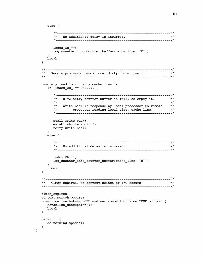
100
else {
/*----------------------------------------------------------*/ /* No additional delay is incurred. */ /*----------------------------------------------------------*/
index_CB_++; log_counter_into_counter_buffer(cache_line, "E"); } break; }
/*----------------------------------------------------------------*/ /* Remote processor reads local dirty cache line. */ /*----------------------------------------------------------------*/
remotely_read_local_dirty_cache_line: { if (index_CB_ == 0x2000) {
/*----------------------------------------------------------*/ /* 8192-entry counter buffer is full, so empty it. */ /* */ /* Write-back is response by local processor to remote */ /* processor reading local dirty cache line. */ /*----------------------------------------------------------*/
stall write-back; establish_checkpoint(); retry write-back; } else {
/*----------------------------------------------------------*/ /* No additional delay is incurred. */ /*----------------------------------------------------------*/
index_CB_++; log_counter_into_counter_buffer(cache_line, "R"); } break; }
/*----------------------------------------------------------------*/ /* Timer expires, or context switch or I/O occurs. */ /*----------------------------------------------------------------*/
timer_expires: context_switch_occurs: communication_between_CPU_and_environment_outside_TCMP_occurs: { establish_checkpoint(); break; }
default: { do nothing special; }}
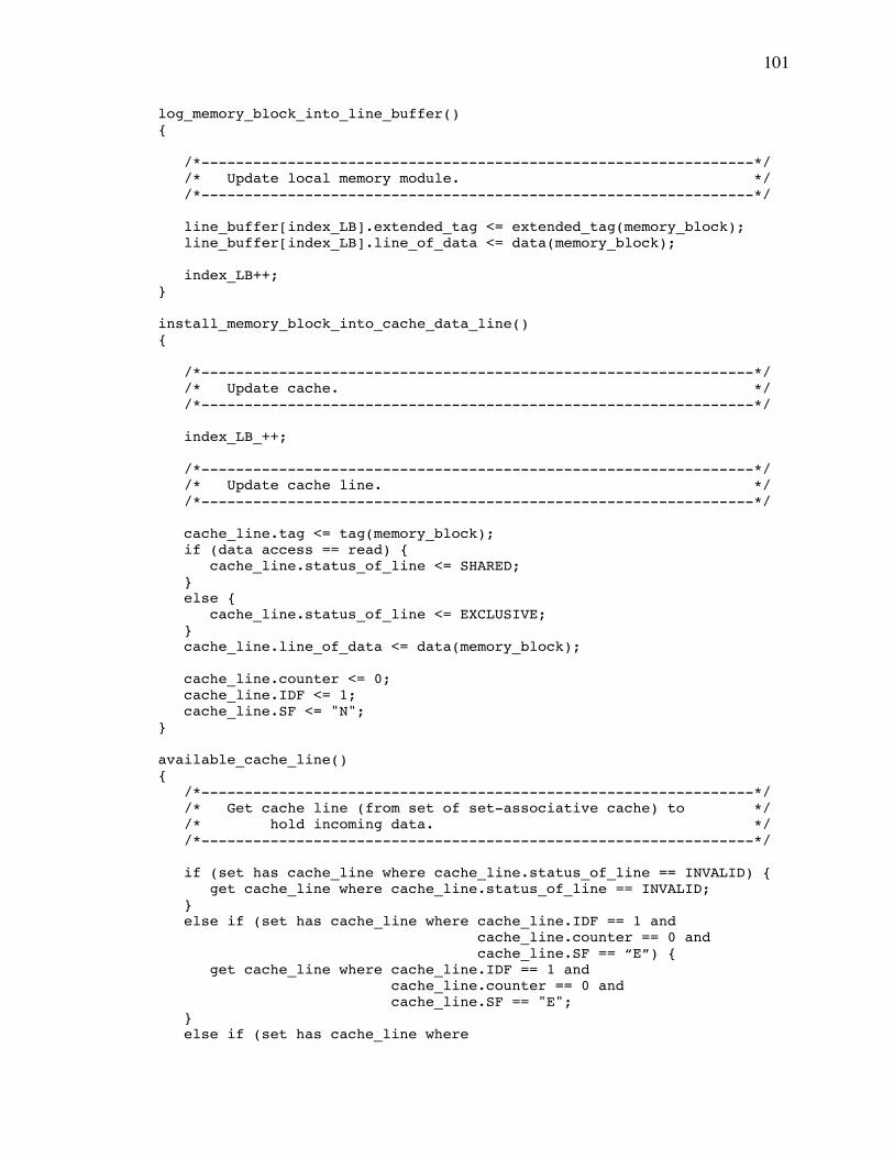
101
log_memory_block_into_line_buffer(){
/*----------------------------------------------------------------*/ /* Update local memory module. */ /*----------------------------------------------------------------*/
line_buffer[index_LB].extended_tag <= extended_tag(memory_block); line_buffer[index_LB].line_of_data <= data(memory_block);
index_LB++;}
install_memory_block_into_cache_data_line(){
/*----------------------------------------------------------------*/ /* Update cache. */ /*----------------------------------------------------------------*/
index_LB_++;
/*----------------------------------------------------------------*/ /* Update cache line. */ /*----------------------------------------------------------------*/
cache_line.tag <= tag(memory_block); if (data access == read) { cache_line.status_of_line <= SHARED; } else { cache_line.status_of_line <= EXCLUSIVE; } cache_line.line_of_data <= data(memory_block);
cache_line.counter <= 0; cache_line.IDF <= 1; cache_line.SF <= "N";}
available_cache_line(){ /*----------------------------------------------------------------*/ /* Get cache line (from set of set-associative cache) to */ /* hold incoming data. */ /*----------------------------------------------------------------*/
if (set has cache_line where cache_line.status_of_line == INVALID) { get cache_line where cache_line.status_of_line == INVALID; } else if (set has cache_line where cache_line.IDF == 1 and cache_line.counter == 0 and cache_line.SF == ÒEÓ) { get cache_line where cache_line.IDF == 1 and cache_line.counter == 0 and cache_line.SF == "E"; } else if (set has cache_line where
102
cache_line.IDF == 1 and cache_line.counter == 0 and cache_line.SF == ÒVÓ and sorted_counter_buffer[entry].counter == 0 and sorted_counter_buffer[entry].SF == ÒEÓ and extended_tag(cache_line) == sorted_counter_buffer[entry].extended_tag for next matching entry in sorted counter buffer) {
/*-------------------------------------------------------------*/ /* Set can have cache_line where */ /* */ /* cache_line.IDF == 1, */ /* cache_line.counter == 0, */ /* cache_line.SF == ÒVÓ, */ /* sorted_counter_buffer[entry].counter == 0, */ /* sorted_counter_buffer[entry].SF == ÒEÓ, and */ /* extended_tag(cache_line) == */ /* sorted_counter_buffer[entry].extended_tag */ /* */ /* for next matching entry in sorted counter buffer. */ /* */ /* Situation can arise, for example, if immediately after */ /* establishing checkpoint, processor resumes normal */ /* execution and issues data access that experiences */ /* conflict miss, which evicts cache line. */ /*-------------------------------------------------------------*/
get cache_line where cache_line.IDF == 1 and cache_line.counter == 0 and cache_line.SF == ÒVÓ and sorted_counter_buffer[entry].counter == 0 and sorted_counter_buffer[entry].SF == ÒEÓ and extended_tag(cache_line) == sorted_counter_buffer[entry].extended_tag for next matching entry in sorted counter buffer;
/*-------------------------------------------------------------*/ /* Retrieve and discard matching entry mentioned */ /* in directly preceding statement. */ /*-------------------------------------------------------------*/
retrieve and discard next entry from sorted counter buffer, which matches cache_line; } else { get cache_line where cache_line.IDF == 0; }
return cache_line;}
install_memory_block_into_cache_instruction_line(){
/*----------------------------------------------------------------*/ /* Update cache line. */
103
/*----------------------------------------------------------------*/
cache_line.tag <= tag(memory_block); cache_line.status_of_line <= SHARED; cache_line.line_of_data <= data(memory_block);
cache_line.counter <= 0; cache_line.IDF <= 0; cache_line.SF <= "N";}
log_counter_into_counter_buffer(cache_line, event){
/*----------------------------------------------------------------*/ /* Update local memory module. */ /*----------------------------------------------------------------*/
counter_buffer[index_CB].extended_tag <= extended_tag(cache_line); counter_buffer[index_CB].counter <= cache_line.counter;
/*----------------------------------------------------------------*/ /* "event" can be one of {"V", "E", "R"}. */ /* */ /* "V" = overflow of counter */ /* "E" = ejection of cache line due to eviction or */ /* invalidation */ /* "R" = (remotely) reading local cache line */ /*----------------------------------------------------------------*/
counter_buffer[index_CB].SF <= event;
index_CB++;}
establish_checkpoint(){ CSB.CF <= TENTATIVE_CHECKPOINT_IS_ACTIVE; wait until all pending memory accesses are completed or negatively acknowledged; negatively acknowledge all cache-coherence messages until checkpoint is established; establish_tentative_checkpoint();
CSB.CF <= PERMANENT_CHECKPOINT_IS_ACTIVE; establish_permanent_checkpoint();
/*----------------------------------------------------------------*/ /* Established checkpoint. */ /*----------------------------------------------------------------*/
CSB.CF <= CHECKPOINT_IS_NOT_ACTIVE;}
establish_tentative_checkpoint(){ /*----------------------------------------------------------------*/ /* CSB.toggle_flag toggles between 0 and 1. */
104
/*----------------------------------------------------------------*/
i <= 1 - CSB.toggle_flag; save tag, status_of_line, line_of_data, and IDF of all cache lines into CSB.checkpoint_area[i].cache; save internal state of processor into CSB.checkpoint_area[i].processor_state; CSB.checkpoint_area[i].status <= TENTATIVE_CHECKPOINT_AREA;
}
establish_permanent_checkpoint(){ /*----------------------------------------------------------------*/ /* Establish permanent checkpoint. */ /*----------------------------------------------------------------*/
index_LB_ <= 0; index_CB_ <= 0;
index_LB <= 0; index_CB <= 0;
for (each cache_line in cache) { cache_line.counter <= 0; }
i <= CSB.toggle_flag; CSB.checkpoint_area[i].status <= NULL;
i <= 1 - CSB.toggle_flag; CSB.checkpoint_area[i].status <= PERMANENT_CHECKPOINT_AREA; CSB.toggle_flag <= i;}
complete_permanent_checkpoint(){ /*----------------------------------------------------------------*/ /* Establish permanent checkpoint. */ /*----------------------------------------------------------------*/
index_LB_ <= 0; index_CB_ <= 0;
index_LB <= 0; index_CB <= 0;
for (each cache_line in cache) { cache_line.counter <= 0; }
j <= CSB.toggle_flag; if ((CSB.checkpoint_area[j].status == PERMANENT_CHECKPOINT_AREA) && (CSB.checkpoint_area[1 - j].status == TENTATIVE_CHECKPOINT_AREA)) {
i <= CSB.toggle_flag; CSB.checkpoint_area[i].status <= NULL;
105
i <= 1 - CSB.toggle_flag; CSB.checkpoint_area[i].status <= PERMANENT_CHECKPOINT_AREA; CSB.toggle_flag <= i; } else if ((CSB.checkpoint_area[j].status == NULL) && (CSB.checkpoint_area[1 - j].status == TENTATIVE_CHECKPOINT_AREA)) {
i <= 1 - CSB.toggle_flag; CSB.checkpoint_area[i].status <= PERMANENT_CHECKPOINT_AREA; CSB.toggle_flag <= i; } else if ((CSB.checkpoint_area[j].status == NULL) && (CSB.checkpoint_area[1 - j].status == PERMANENT_CHECKPOINT_AREA)) {
CSB.toggle_flag <= 1 - j; } else { do nothing special; }}
fault detection---------------if (RLC detects fault in processor module) {
if (fault == permanent) { replace processor module with spare processor module; reset spare processor module, invalidating all entries in both 1st-level cache and 2nd-level cache; } else { reset processor module, invalidating all entries in both 1st-level cache and 2nd-level cache; }
trap to virtual-machine monitor;
query all memory modules to find lost cache-coherence messages; negatively acknowledge all cache-coherence messages until recovery is complete;
if (CSB.CF == PERMANENT_CHECKPOINT_IS_ACTIVE) { complete_permanent_checkpoint();
i <= CSB.toggle_flag; if (CSB.checkpoint_area[i].status != PERMANENT_CHECKPOINT_AREA) { i = 1 - CSB.toggle_flag; }
load internal state of processor from CSB.checkpoint_area[i].processor_state; for (each cache_line in cache) { load cache_line from CSB.checkpoint_area[i].cache;
cache_line.counter <= 0; }
return from trap to virtual-machine monitor;
106
exit and resume normal execution; }
if (CSB.CF == TENTATIVE_CHECKPOINT_IS_ACTIVE) { i <= 1 - CSB.toggle_flag; CSB.checkpoint_area[i].status <= NULL;
CSB.CF <= CHECKPOINT_IS_NOT_ACTIVE;
discard tentative checkpoint; }
read all valid entries from line buffer; group all entries according to cache index but, for each cache index, maintain the temporal order in which the entries were originally inserted into the line buffer; place grouped entries into sorted_line_buffer;
read all valid entries from counter buffer; group all entries according to cache index but, for each cache index, maintain the temporal order in which the entries were originally inserted into the counter buffer; place grouped entries into sorted_counter_buffer;
i <= CSB.toggle_flag; if (CSB.checkpoint_area[i].status != PERMANENT_CHECKPOINT_AREA) { i = 1 - CSB.toggle_flag; }
load internal state of processor from CSB.checkpoint_area[i].processor_state; for (each cache_line in cache) { load cache_line from CSB.checkpoint_area[i].cache;
cache_line.counter <= 0; cache_line.SF <= "V"; }
return from trap to virtual-machine monitor;
enter recovery mode of execution;}
execution mode: recovery--------------------------switch (event) {
/*----------------------------------------------------------------*/ /* Upgrade miss occurs in cache data line. */ /* */ /* Upgrade miss occurs when data-write ÒhitsÓ in cache */ /* line with status being SHARED. */ /*----------------------------------------------------------------*/
data_write_has_upgrade_miss_in_cache_data_line: { stall data-write;
cache_line.status_of_line <= EXCLUSIVE;

107
/*-------------------------------------------------------------*/ /* Retry data-write. */ /* */ /* It then will hit in cache data line and will generate */ /* Òdata_access_hits_in_cache_data_lineÓ as next */ /* event. */ /*-------------------------------------------------------------*/
retry data-write;
break; }
/*----------------------------------------------------------------*/ /* Access misses in cache data line. */ /*----------------------------------------------------------------*/
data_access_misses_in_cache_data_line: { stall data access;
trap to virtual-machine monitor; cache_line <= available_cache_line(); get_entry_from_sorted_line_buffer(cache_line) get_entry_from_sorted_counter_buffer(cache_line); return from trap to virtual-machine monitor;
retry data access;
exit_recovery_upon_completion();
break; }
memory_block_arrives: { if (original access is data access) {
/*----------------------------------------------------------*/ /* Data is supplied from sorted line buffer. */ /*----------------------------------------------------------*/
; } else { cache_line <= available_cache_line(); install_memory_block_into_cache_instruction_line(); } break; }
/*----------------------------------------------------------------*/ /* Access hits in cache line. */ /*----------------------------------------------------------------*/
data_access_hits_in_cache_data_line: { switch (cache_line.SF) {
"N": {
108
cache_line.counter <= 0; break; }
"E": { if (cache_line.counter != 0) { cache_line.counter--; } else { stall data access;
trap to virtual-machine monitor; cache_line.status_of_line <= INVALID; get_entry_from_sorted_line_buffer(cache_line) get_entry_from_sorted_counter_buffer(cache_line); return from trap to virtual-machine monitor;
retry data access; } break; }
"R": { if (cache_line.counter != 0) { cache_line.counter--; } else { stall data access;
trap to virtual-machine monitor; cache_line.status_of_line <= SHARED; get_entry_from_sorted_counter_buffer(cache_line); return from trap to virtual-machine monitor;
retry data access; } break; }
"V": { if (cache_line.counter != 0) { cache_line.counter--; } else { stall data access;
trap to virtual-machine monitor; get_entry_from_sorted_counter_buffer(cache_line); return from trap to virtual-machine monitor;
retry data access; } break; } } exit_recovery_upon_completion(); break; }
109
default: { exit_recovery_upon_completion(); break; }}
write_back_and_invalidate_cache_lines(){ i <= CSB.toggle_flag; if (CSB.checkpoint_area[i].status != PERMANENT_CHECKPOINT_AREA) { i <= 1 Ð CSB.toggle_flag; }
for (each dirty cache_line in CSB.checkpoint_area[i].cache) { write cache_line back into main memory; } for (each cache_line in CSB.checkpoint_area[i].cache) { cache_line.status_of_line <= INVALID; }
tell the directory controller of each memory module to change the status of any memory block (i. e. cache line) held by the cache (of the local processor) to indicate that the cache no longer holds the memory block;
for (each cache_line in cache of local processor) { cache_line.status_of_line <= INVALID; }}
exit_recovery_upon_completion(){ if ((sorted_counter_buffer has no entry where SF is ÒEÓ or ÒRÓ) &&(counters in all valid cache data lines where SF is ÒEÓ or ÒRÓ are 0)){
/*-------------------------------------------------------------*/ /* Completion of recovery is imminent. */ /* */ /* Update state of cache. */ /*-------------------------------------------------------------*/
for (each valid cache_line in cache) { switch (cache_line.SF) { "E": { cache_line.status_of_line <= INVALID; break; } "R": { cache_line.status_of_line <= SHARED; break; } default: { break; } } }

110
establish_checkpoint();
write_back_and_invalidate_cache_lines();
/*-------------------------------------------------------------*/ /* Recovery is complete. */ /*-------------------------------------------------------------*/
exit recovery and resume normal execution;
} else {
/*-------------------------------------------------------------*/ /* Completion of recovery is not imminent. */ /*-------------------------------------------------------------*/
; }}
get_entry_from_sorted_line_buffer(cache_line){ /*----------------------------------------------------------------*/ /* Get matching entry from sorted_line_buffer. */ /*----------------------------------------------------------------*/
get next matching entry from sorted_line_buffer;
cache_line.tag <= tag(sorted_line_buffer[entry].extended_tag); if (data-access == write) { cache_line.status_of_line <= EXCLUSIVE; } else cache_line.status_of_line <= SHARED; } cache_line.line_of_data <= sorted_line_buffer[entry].line_of_data;}
get_entry_from_sorted_counter_buffer(cache_line){ /*----------------------------------------------------------------*/ /* Get matching entry from sorted_counter_buffer. */ /*----------------------------------------------------------------*/
get next matching entry from sorted_counter_buffer;
if (no matching counter) { cache_line.counter <= 0; cache_line.IDF <= 1; cache_line.SF <= "N"; } else { cache_line.counter <= sorted_counter_buffer[entry].counter; cache_line.IDF <= 1; cache_line.SF <= sorted_counter_buffer[entry].SF; }

111
}
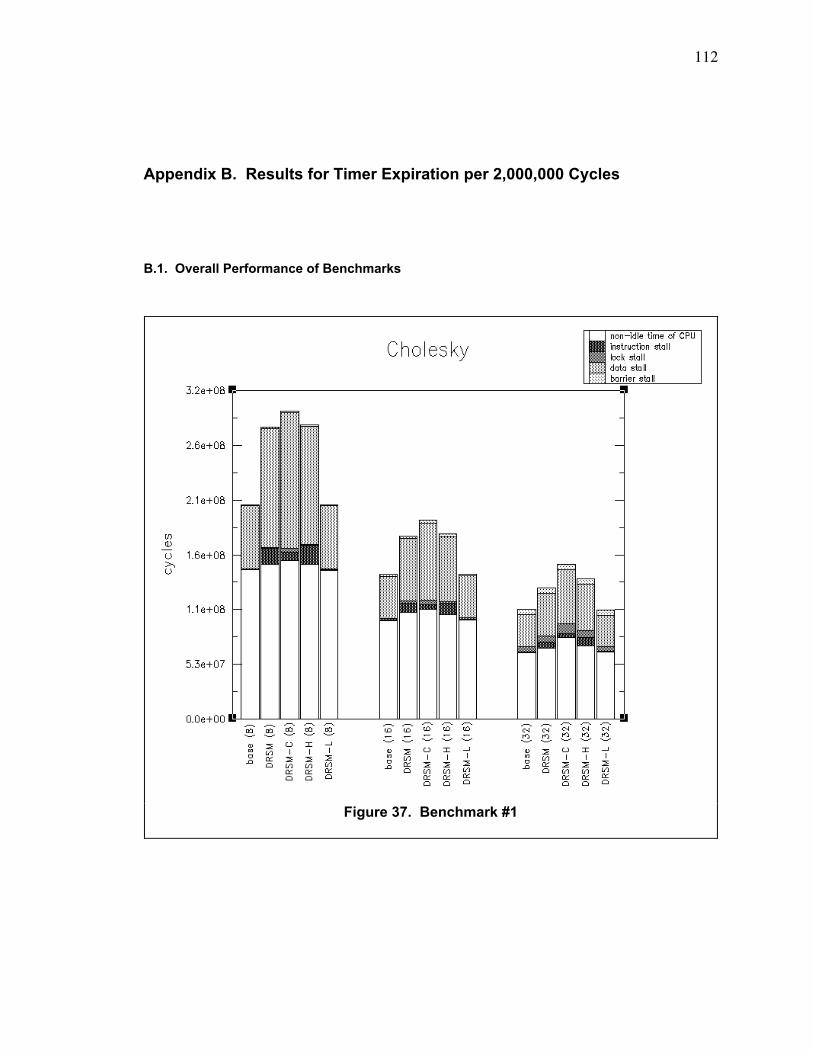
112
Appendix B. Results for Timer Expiration per 2,000,000 Cycles
B.1. Overall Performance of Benchmarks
Figure 37. Benchmark #1
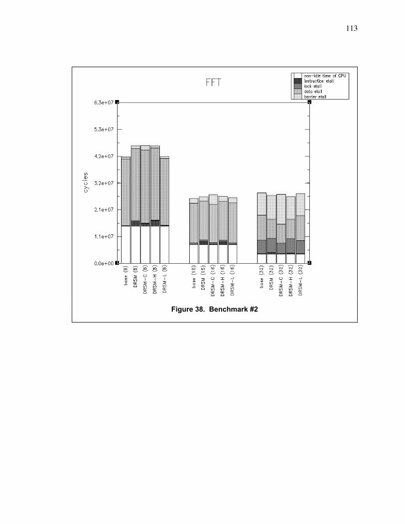
113
Figure 38. Benchmark #2
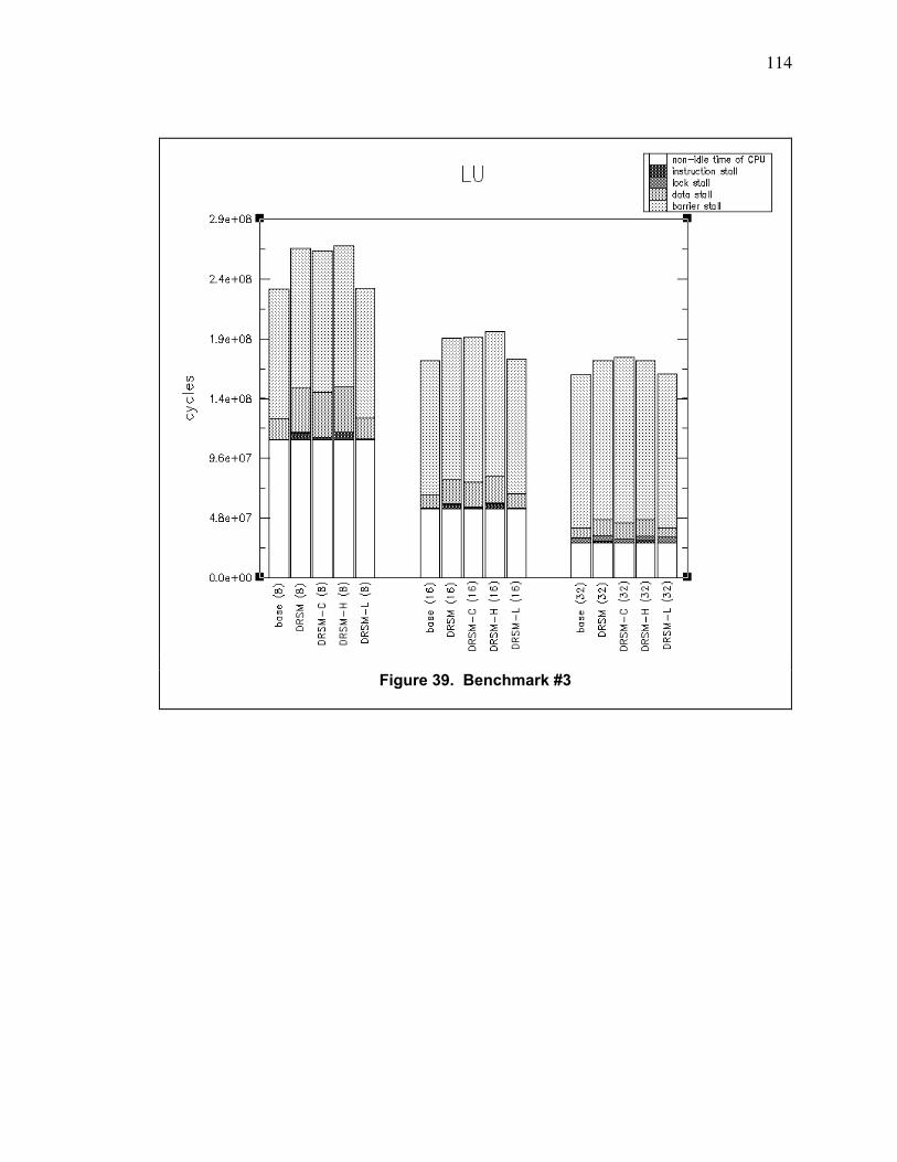
114
Figure 39. Benchmark #3
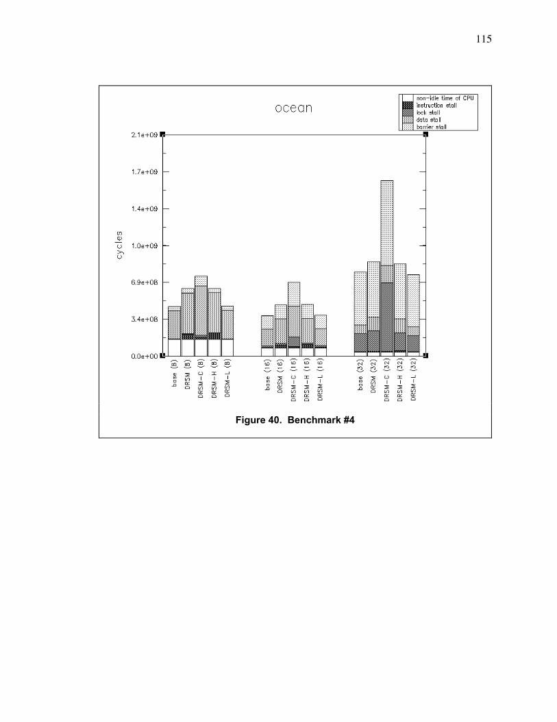
115
Figure 40. Benchmark #4
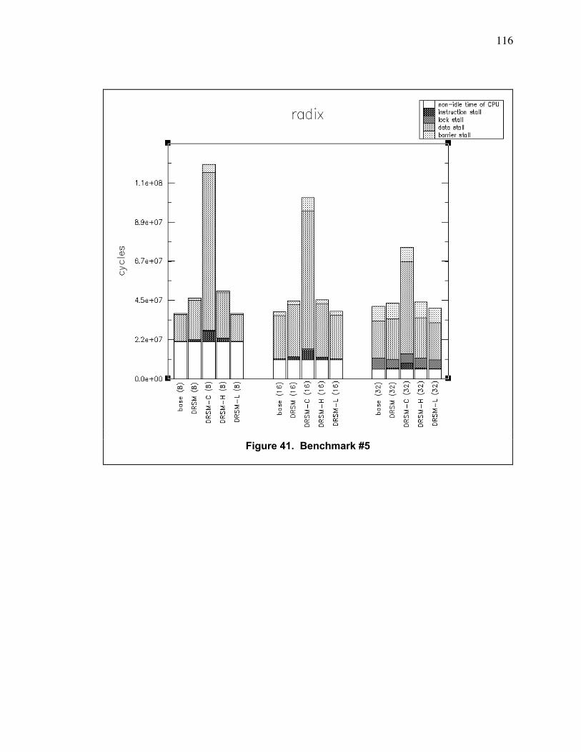
116
Figure 41. Benchmark #5
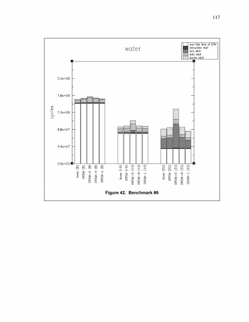
117
Figure 42. Benchmark #6
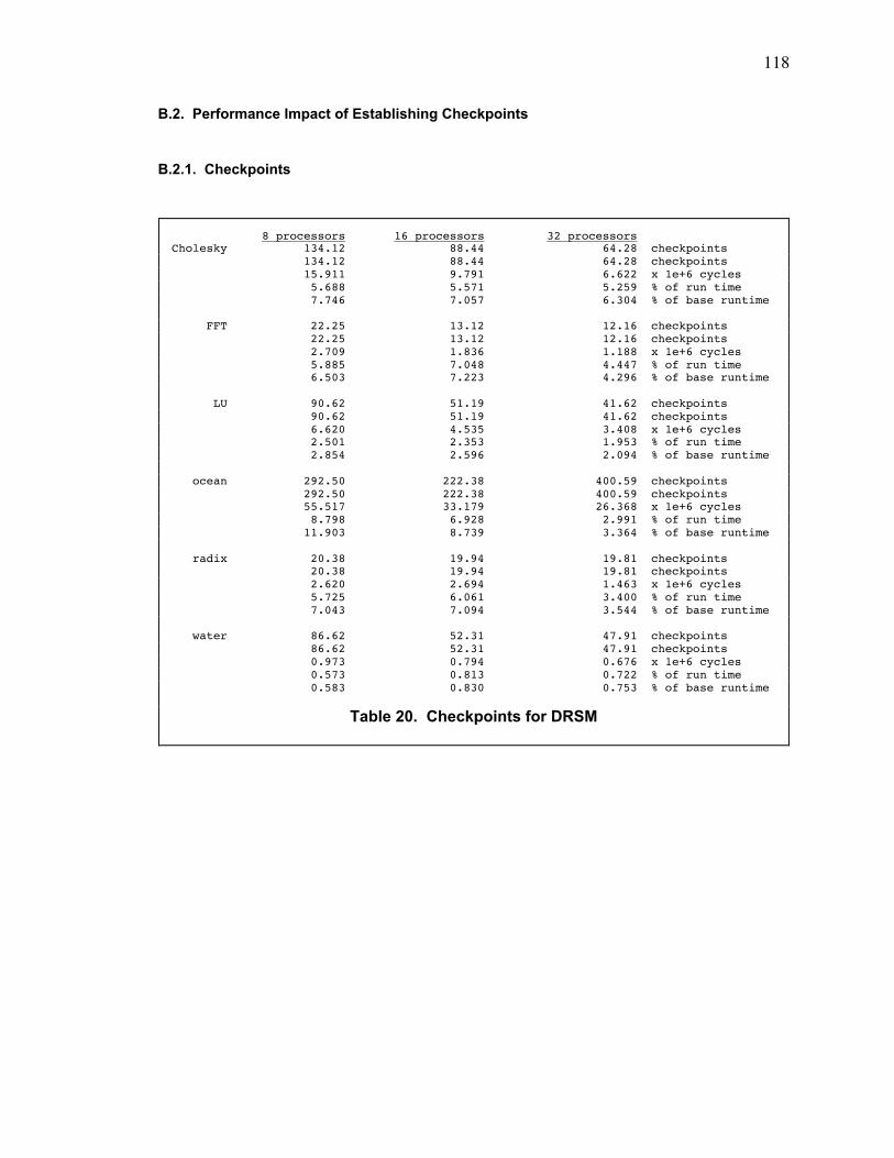
118
B.2. Performance Impact of Establishing Checkpoints
B.2.1. Checkpoints
8 processors 16 processors 32 processorsCholesky 134.12 88.44 64.28 checkpoints 134.12 88.44 64.28 checkpoints 15.911 9.791 6.622 x 1e+6 cycles 5.688 5.571 5.259 % of run time 7.746 7.057 6.304 % of base runtime
FFT 22.25 13.12 12.16 checkpoints 22.25 13.12 12.16 checkpoints 2.709 1.836 1.188 x 1e+6 cycles 5.885 7.048 4.447 % of run time 6.503 7.223 4.296 % of base runtime
LU 90.62 51.19 41.62 checkpoints 90.62 51.19 41.62 checkpoints 6.620 4.535 3.408 x 1e+6 cycles 2.501 2.353 1.953 % of run time 2.854 2.596 2.094 % of base runtime
ocean 292.50 222.38 400.59 checkpoints 292.50 222.38 400.59 checkpoints 55.517 33.179 26.368 x 1e+6 cycles 8.798 6.928 2.991 % of run time 11.903 8.739 3.364 % of base runtime
radix 20.38 19.94 19.81 checkpoints 20.38 19.94 19.81 checkpoints 2.620 2.694 1.463 x 1e+6 cycles 5.725 6.061 3.400 % of run time 7.043 7.094 3.544 % of base runtime
water 86.62 52.31 47.91 checkpoints 86.62 52.31 47.91 checkpoints 0.973 0.794 0.676 x 1e+6 cycles 0.573 0.813 0.722 % of run time 0.583 0.830 0.753 % of base runtime
Table 20. Checkpoints for DRSM
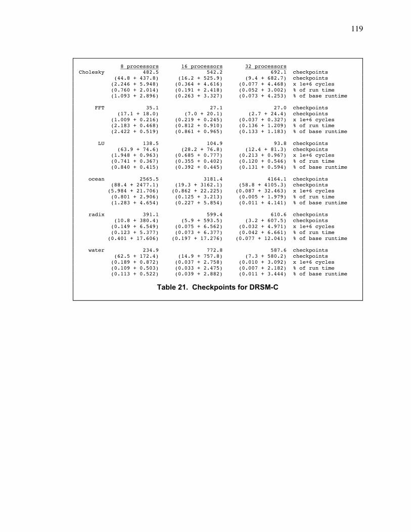
119
8 processors 16 processors 32 processorsCholesky 482.5 542.2 692.1 checkpoints (44.8 + 437.8) (16.2 + 525.9) (9.4 + 682.7) checkpoints (2.246 + 5.948) (0.364 + 4.616) (0.077 + 4.468) x 1e+6 cycles (0.760 + 2.014) (0.191 + 2.418) (0.052 + 3.002) % of run time (1.093 + 2.896) (0.263 + 3.327) (0.073 + 4.253) % of base runtime
FFT 35.1 27.1 27.0 checkpoints (17.1 + 18.0) (7.0 + 20.1) (2.7 + 24.4) checkpoints (1.009 + 0.216) (0.219 + 0.245) (0.037 + 0.327) x 1e+6 cycles (2.183 + 0.468) (0.812 + 0.910) (0.136 + 1.209) % of run time (2.422 + 0.519) (0.861 + 0.965) (0.133 + 1.183) % of base runtime
LU 138.5 104.9 93.8 checkpoints (63.9 + 74.6) (28.2 + 76.8) (12.4 + 81.3) checkpoints (1.948 + 0.963) (0.685 + 0.777) (0.213 + 0.967) x 1e+6 cycles (0.741 + 0.367) (0.355 + 0.402) (0.120 + 0.546) % of run time (0.840 + 0.415) (0.392 + 0.445) (0.131 + 0.594) % of base runtime
ocean 2565.5 3181.4 4164.1 checkpoints (88.4 + 2477.1) (19.3 + 3162.1) (58.8 + 4105.3) checkpoints (5.984 + 21.706) (0.862 + 22.225) (0.087 + 32.463) x 1e+6 cycles (0.801 + 2.906) (0.125 + 3.213) (0.005 + 1.979) % of run time (1.283 + 4.654) (0.227 + 5.854) (0.011 + 4.141) % of base runtime
radix 391.1 599.4 610.6 checkpoints (10.8 + 380.4) (5.9 + 593.5) (3.2 + 607.5) checkpoints (0.149 + 6.549) (0.075 + 6.562) (0.032 + 4.971) x 1e+6 cycles (0.123 + 5.377) (0.073 + 6.377) (0.042 + 6.661) % of run time (0.401 + 17.606) (0.197 + 17.276) (0.077 + 12.041) % of base runtime
water 234.9 772.8 587.6 checkpoints (62.5 + 172.4) (14.9 + 757.8) (7.3 + 580.2) checkpoints (0.189 + 0.872) (0.037 + 2.758) (0.010 + 3.092) x 1e+6 cycles (0.109 + 0.503) (0.033 + 2.475) (0.007 + 2.182) % of run time (0.113 + 0.522) (0.039 + 2.882) (0.011 + 3.444) % of base runtime
Table 21. Checkpoints for DRSM-C
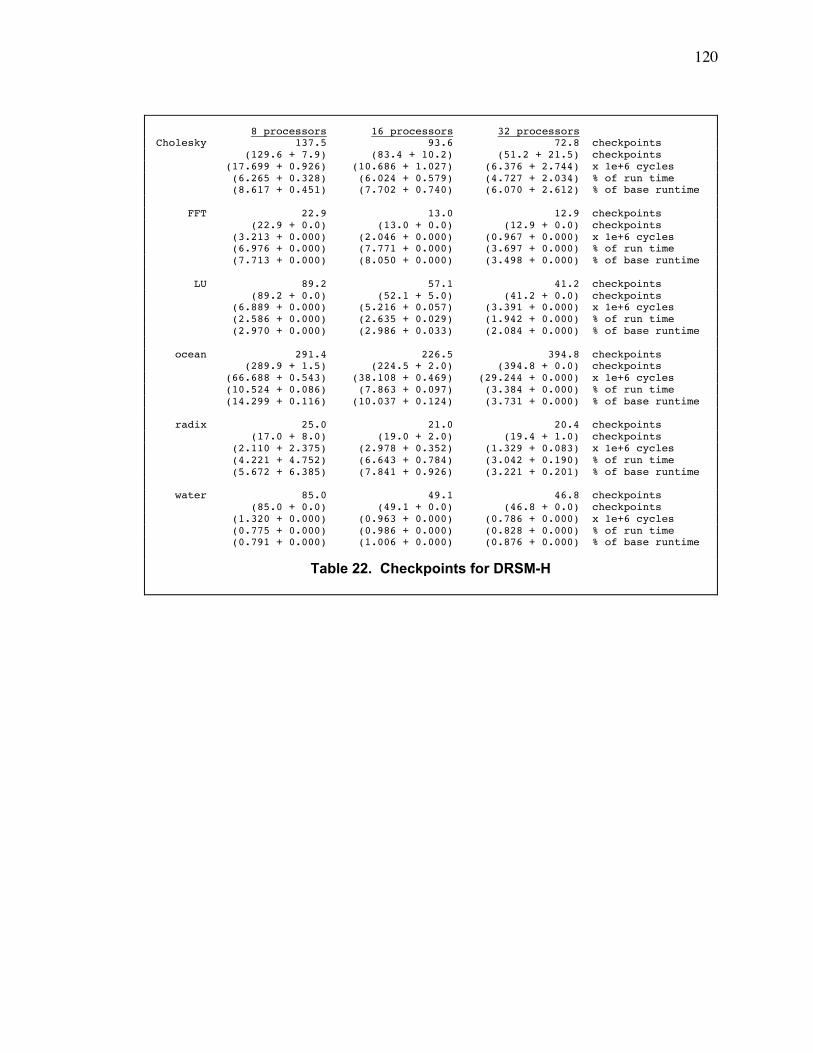
120
8 processors 16 processors 32 processorsCholesky 137.5 93.6 72.8 checkpoints (129.6 + 7.9) (83.4 + 10.2) (51.2 + 21.5) checkpoints (17.699 + 0.926) (10.686 + 1.027) (6.376 + 2.744) x 1e+6 cycles (6.265 + 0.328) (6.024 + 0.579) (4.727 + 2.034) % of run time (8.617 + 0.451) (7.702 + 0.740) (6.070 + 2.612) % of base runtime
FFT 22.9 13.0 12.9 checkpoints (22.9 + 0.0) (13.0 + 0.0) (12.9 + 0.0) checkpoints (3.213 + 0.000) (2.046 + 0.000) (0.967 + 0.000) x 1e+6 cycles (6.976 + 0.000) (7.771 + 0.000) (3.697 + 0.000) % of run time (7.713 + 0.000) (8.050 + 0.000) (3.498 + 0.000) % of base runtime
LU 89.2 57.1 41.2 checkpoints (89.2 + 0.0) (52.1 + 5.0) (41.2 + 0.0) checkpoints (6.889 + 0.000) (5.216 + 0.057) (3.391 + 0.000) x 1e+6 cycles (2.586 + 0.000) (2.635 + 0.029) (1.942 + 0.000) % of run time (2.970 + 0.000) (2.986 + 0.033) (2.084 + 0.000) % of base runtime
ocean 291.4 226.5 394.8 checkpoints (289.9 + 1.5) (224.5 + 2.0) (394.8 + 0.0) checkpoints (66.688 + 0.543) (38.108 + 0.469) (29.244 + 0.000) x 1e+6 cycles (10.524 + 0.086) (7.863 + 0.097) (3.384 + 0.000) % of run time (14.299 + 0.116) (10.037 + 0.124) (3.731 + 0.000) % of base runtime
radix 25.0 21.0 20.4 checkpoints (17.0 + 8.0) (19.0 + 2.0) (19.4 + 1.0) checkpoints (2.110 + 2.375) (2.978 + 0.352) (1.329 + 0.083) x 1e+6 cycles (4.221 + 4.752) (6.643 + 0.784) (3.042 + 0.190) % of run time (5.672 + 6.385) (7.841 + 0.926) (3.221 + 0.201) % of base runtime
water 85.0 49.1 46.8 checkpoints (85.0 + 0.0) (49.1 + 0.0) (46.8 + 0.0) checkpoints (1.320 + 0.000) (0.963 + 0.000) (0.786 + 0.000) x 1e+6 cycles (0.775 + 0.000) (0.986 + 0.000) (0.828 + 0.000) % of run time (0.791 + 0.000) (1.006 + 0.000) (0.876 + 0.000) % of base runtime
Table 22. Checkpoints for DRSM-H
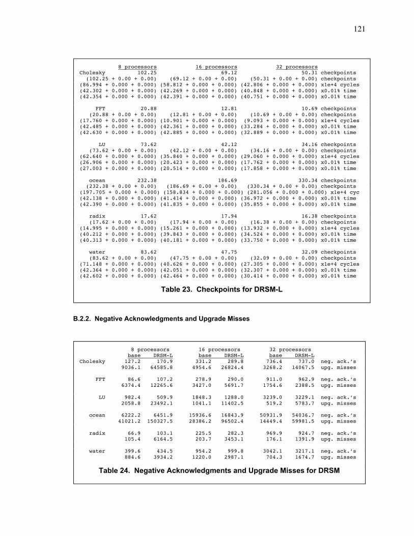
121
B.2.2. Negative Acknowledgments and Upgrade Misses
8 processors 16 processors 32 processorsCholesky 102.25 69.12 50.31 checkpoints (102.25 + 0.00 + 0.00) (69.12 + 0.00 + 0.00) (50.31 + 0.00 + 0.00) checkpoints(86.994 + 0.000 + 0.000) (58.812 + 0.000 + 0.000) (42.806 + 0.000 + 0.000) x1e+4 cycles(42.302 + 0.000 + 0.000) (42.269 + 0.000 + 0.000) (40.848 + 0.000 + 0.000) x0.01% time(42.354 + 0.000 + 0.000) (42.391 + 0.000 + 0.000) (40.751 + 0.000 + 0.000) x0.01% time
FFT 20.88 12.81 10.69 checkpoints (20.88 + 0.00 + 0.00) (12.81 + 0.00 + 0.00) (10.69 + 0.00 + 0.00) checkpoints(17.760 + 0.000 + 0.000) (10.901 + 0.000 + 0.000) (9.093 + 0.000 + 0.000) x1e+4 cycles(42.485 + 0.000 + 0.000) (42.361 + 0.000 + 0.000) (33.284 + 0.000 + 0.000) x0.01% time(42.630 + 0.000 + 0.000) (42.885 + 0.000 + 0.000) (32.889 + 0.000 + 0.000) x0.01% time
LU 73.62 42.12 34.16 checkpoints (73.62 + 0.00 + 0.00) (42.12 + 0.00 + 0.00) (34.16 + 0.00 + 0.00) checkpoints(62.640 + 0.000 + 0.000) (35.840 + 0.000 + 0.000) (29.060 + 0.000 + 0.000) x1e+4 cycles(26.906 + 0.000 + 0.000) (20.423 + 0.000 + 0.000) (17.762 + 0.000 + 0.000) x0.01% time(27.003 + 0.000 + 0.000) (20.514 + 0.000 + 0.000) (17.858 + 0.000 + 0.000) x0.01% time
ocean 232.38 186.69 330.34 checkpoints (232.38 + 0.00 + 0.00) (186.69 + 0.00 + 0.00) (330.34 + 0.00 + 0.00) checkpoints(197.705 + 0.000 + 0.000) (158.834 + 0.000 + 0.000) (281.056 + 0.000 + 0.000) x1e+4 cyc(42.138 + 0.000 + 0.000) (41.414 + 0.000 + 0.000) (36.972 + 0.000 + 0.000) x0.01% time(42.390 + 0.000 + 0.000) (41.835 + 0.000 + 0.000) (35.855 + 0.000 + 0.000) x0.01% time
radix 17.62 17.94 16.38 checkpoints (17.62 + 0.00 + 0.00) (17.94 + 0.00 + 0.00) (16.38 + 0.00 + 0.00) checkpoints(14.995 + 0.000 + 0.000) (15.261 + 0.000 + 0.000) (13.932 + 0.000 + 0.000) x1e+4 cycles(40.212 + 0.000 + 0.000) (39.843 + 0.000 + 0.000) (34.524 + 0.000 + 0.000) x0.01% time(40.313 + 0.000 + 0.000) (40.181 + 0.000 + 0.000) (33.750 + 0.000 + 0.000) x0.01% time
water 83.62 47.75 32.09 checkpoints (83.62 + 0.00 + 0.00) (47.75 + 0.00 + 0.00) (32.09 + 0.00 + 0.00) checkpoints(71.148 + 0.000 + 0.000) (40.626 + 0.000 + 0.000) (27.305 + 0.000 + 0.000) x1e+4 cycles(42.364 + 0.000 + 0.000) (42.051 + 0.000 + 0.000) (32.307 + 0.000 + 0.000) x0.01% time(42.602 + 0.000 + 0.000) (42.464 + 0.000 + 0.000) (30.414 + 0.000 + 0.000) x0.01% time
Table 23. Checkpoints for DRSM-L
8 processors 16 processors 32 processors base DRSM-L base DRSM-L base DRSM-LCholesky 127.2 170.9 331.2 289.8 736.4 737.0 neg. ack.Õs 9036.1 64585.8 4954.6 26824.4 3268.2 14067.5 upg. misses
FFT 86.6 107.2 278.9 290.0 911.0 962.9 neg. ack.Õs 6374.4 12265.6 3427.0 5691.7 1754.6 2388.5 upg. misses
LU 982.4 509.9 1848.3 1288.0 3239.0 3229.1 neg. ack.Õs 2058.8 23492.1 1041.1 11402.5 519.2 5783.7 upg. misses
ocean 6222.2 6451.9 15936.6 16843.9 50931.9 54036.7 neg. ack.Õs 41021.2 150327.5 28386.2 96502.4 14449.4 59981.5 upg. misses
radix 66.9 103.1 225.5 282.3 969.9 924.7 neg. ack.Õs 105.4 6164.5 203.7 3453.1 176.1 1391.9 upg. misses
water 399.6 434.5 954.2 999.8 3042.1 3217.1 neg. ack.Õs 884.6 3934.2 1220.0 2987.1 704.3 1674.7 upg. misses
Table 24. Negative Acknowledgments and Upgrade Misses for DRSM
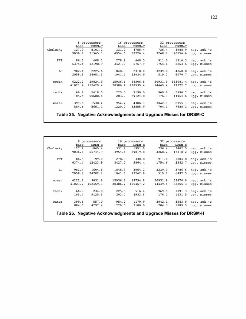
122
8 processors 16 processors 32 processors base DRSM-C base DRSM-C base DRSM-CCholesky 127.2 5103.2 331.2 4755.4 736.4 4988.9 neg. ack.Õs 9036.1 71565.1 4954.6 33776.4 3268.2 20056.6 upg. misses
FFT 86.6 408.1 278.9 648.5 911.0 1316.3 neg. ack.Õs 6374.4 12198.9 3427.0 5767.9 1754.6 2263.6 upg. misses
LU 982.4 2225.6 1848.3 2318.0 3239.0 4068.8 neg. ack.Õs 2058.8 24051.5 1041.1 12034.9 519.2 6070.7 upg. misses
ocean 6222.2 29824.9 15936.6 58306.8 50931.9 133081.4 neg. ack.Õs 41021.2 215429.4 28386.2 138535.4 14449.4 77272.7 upg. misses
radix 66.9 5418.0 225.5 7190.0 969.9 5996.7 neg. ack.Õs 105.4 50680.6 203.7 29124.8 176.1 14964.6 upg. misses
water 399.6 1538.4 954.2 4386.1 3042.1 8955.1 neg. ack.Õs 884.6 5651.1 1220.0 12855.9 704.3 7688.3 upg. misses
Table 25. Negative Acknowledgments and Upgrade Misses for DRSM-C
8 processors 16 processors 32 processors base DRSM-H base DRSM-H base DRSM-HCholesky 127.2 1845.4 331.2 1951.9 736.4 3402.5 neg. ack.Õs 9036.1 66744.9 4954.6 29019.8 3268.2 17318.2 upg. misses
FFT 86.6 199.0 278.9 330.8 911.0 1004.8 neg. ack.Õs 6374.4 12423.9 3427.0 5864.4 1754.6 2382.7 upg. misses
LU 982.4 1604.6 1848.3 3064.2 3239.0 3786.6 neg. ack.Õs 2058.8 24702.2 1041.1 13262.6 519.2 6497.5 upg. misses
ocean 6222.2 9031.6 15936.6 18794.8 50931.9 53470.0 neg. ack.Õs 41021.2 152459.1 28386.2 100467.2 14449.4 62255.3 upg. misses
radix 66.9 234.8 225.5 516.4 969.9 1091.3 neg. ack.Õs 105.4 9125.5 203.7 3932.8 176.1 1431.5 upg. misses
water 399.6 557.0 954.2 1179.9 3042.1 3583.8 neg. ack.Õs 884.6 4297.4 1220.0 3180.0 704.3 1889.5 upg. misses
Table 26. Negative Acknowledgments and Upgrade Misses for DRSM-H
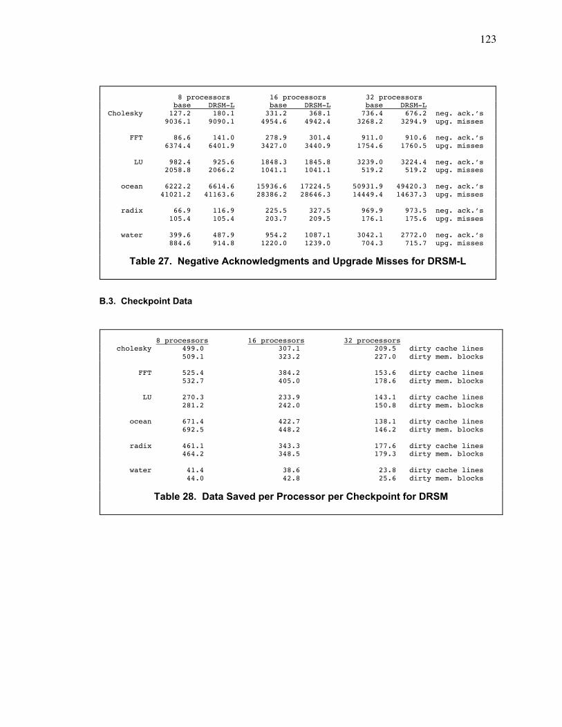
123
B.3. Checkpoint Data
8 processors 16 processors 32 processors base DRSM-L base DRSM-L base DRSM-LCholesky 127.2 180.1 331.2 368.1 736.4 676.2 neg. ack.Õs 9036.1 9090.1 4954.6 4942.4 3268.2 3294.9 upg. misses
FFT 86.6 141.0 278.9 301.4 911.0 910.6 neg. ack.Õs 6374.4 6401.9 3427.0 3440.9 1754.6 1760.5 upg. misses
LU 982.4 925.6 1848.3 1845.8 3239.0 3224.4 neg. ack.Õs 2058.8 2066.2 1041.1 1041.1 519.2 519.2 upg. misses
ocean 6222.2 6614.6 15936.6 17224.5 50931.9 49420.3 neg. ack.Õs 41021.2 41163.6 28386.2 28646.3 14449.4 14637.3 upg. misses
radix 66.9 116.9 225.5 327.5 969.9 973.5 neg. ack.Õs 105.4 105.4 203.7 209.5 176.1 175.6 upg. misses
water 399.6 487.9 954.2 1087.1 3042.1 2772.0 neg. ack.Õs 884.6 914.8 1220.0 1239.0 704.3 715.7 upg. misses
Table 27. Negative Acknowledgments and Upgrade Misses for DRSM-L
8 processors 16 processors 32 processors cholesky 499.0 307.1 209.5 dirty cache lines 509.1 323.2 227.0 dirty mem. blocks
FFT 525.4 384.2 153.6 dirty cache lines 532.7 405.0 178.6 dirty mem. blocks
LU 270.3 233.9 143.1 dirty cache lines 281.2 242.0 150.8 dirty mem. blocks
ocean 671.4 422.7 138.1 dirty cache lines 692.5 448.2 146.2 dirty mem. blocks
radix 461.1 343.3 177.6 dirty cache lines 464.2 348.5 179.3 dirty mem. blocks
water 41.4 38.6 23.8 dirty cache lines 44.0 42.8 25.6 dirty mem. blocks
Table 28. Data Saved per Processor per Checkpoint for DRSM
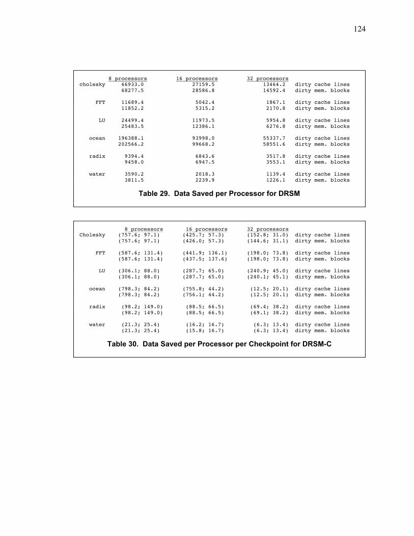
124
8 processors 16 processors 32 processorscholesky 66933.0 27159.5 13464.2 dirty cache lines 68277.5 28586.8 14592.4 dirty mem. blocks
FFT 11689.4 5042.4 1867.1 dirty cache lines 11852.2 5315.2 2170.8 dirty mem. blocks
LU 24499.4 11973.5 5954.8 dirty cache lines 25483.5 12386.1 6276.8 dirty mem. blocks
ocean 196388.1 93998.0 55337.7 dirty cache lines 202566.2 99668.2 58551.6 dirty mem. blocks
radix 9394.4 6843.6 3517.8 dirty cache lines 9458.0 6947.5 3553.1 dirty mem. blocks
water 3590.2 2018.3 1139.4 dirty cache lines 3811.5 2239.9 1226.1 dirty mem. blocks
Table 29. Data Saved per Processor for DRSM
8 processors 16 processors 32 processorsCholesky (757.6; 97.1) (425.7; 57.3) (152.8; 31.0) dirty cache lines (757.6; 97.1) (426.0; 57.3) (144.6; 31.1) dirty mem. blocks
FFT (587.6; 131.4) (441.9; 136.1) (198.0; 73.8) dirty cache lines (587.6; 131.4) (437.5; 137.6) (198.0; 73.8) dirty mem. blocks
LU (306.1; 88.0) (287.7; 65.0) (240.9; 45.0) dirty cache lines (306.1; 88.0) (287.7; 65.0) (240.1; 45.1) dirty mem. blocks
ocean (798.3; 84.2) (755.8; 44.2) (12.5; 20.1) dirty cache lines (798.3; 84.2) (756.1; 44.2) (12.5; 20.1) dirty mem. blocks
radix (98.2; 149.0) (88.5; 66.5) (69.4; 38.2) dirty cache lines (98.2; 149.0) (88.5; 66.5) (69.1; 38.2) dirty mem. blocks
water (21.3; 25.4) (16.2; 16.7) (6.3; 13.4) dirty cache lines (21.3; 25.4) (15.8; 16.7) (6.3; 13.4) dirty mem. blocks
Table 30. Data Saved per Processor per Checkpoint for DRSM-C
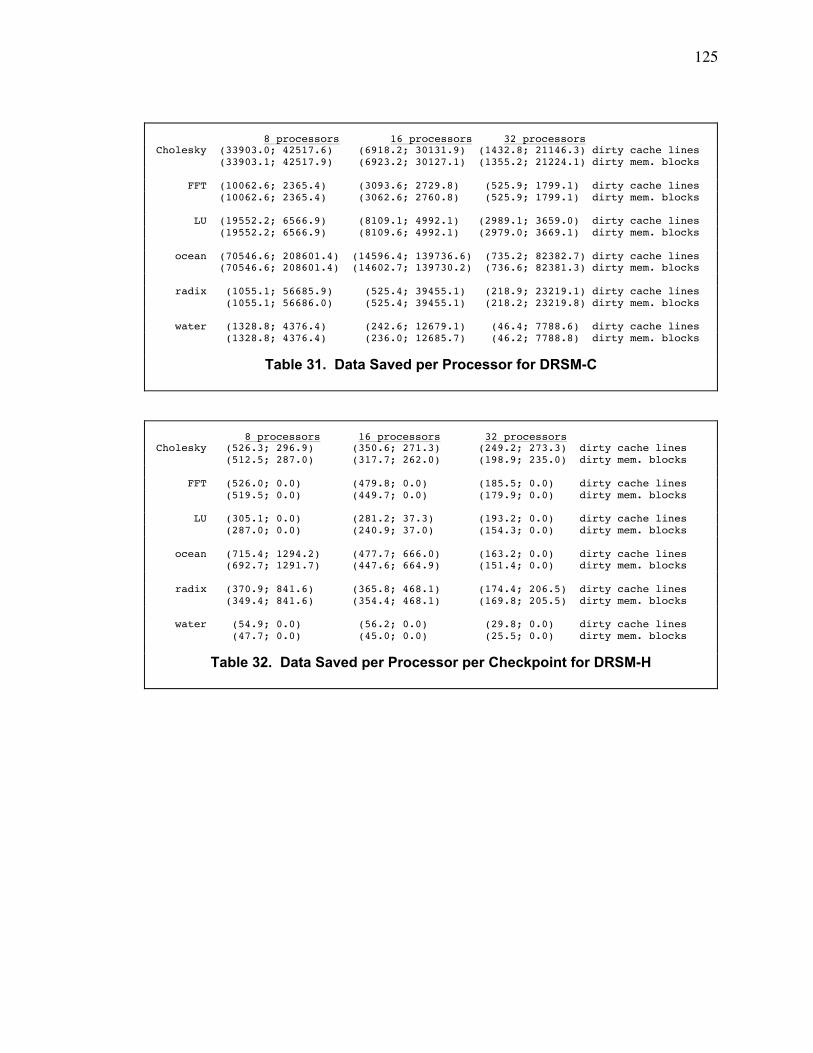
125
8 processors 16 processors 32 processorsCholesky (33903.0; 42517.6) (6918.2; 30131.9) (1432.8; 21146.3) dirty cache lines (33903.1; 42517.9) (6923.2; 30127.1) (1355.2; 21224.1) dirty mem. blocks
FFT (10062.6; 2365.4) (3093.6; 2729.8) (525.9; 1799.1) dirty cache lines (10062.6; 2365.4) (3062.6; 2760.8) (525.9; 1799.1) dirty mem. blocks
LU (19552.2; 6566.9) (8109.1; 4992.1) (2989.1; 3659.0) dirty cache lines (19552.2; 6566.9) (8109.6; 4992.1) (2979.0; 3669.1) dirty mem. blocks
ocean (70546.6; 208601.4) (14596.4; 139736.6) (735.2; 82382.7) dirty cache lines (70546.6; 208601.4) (14602.7; 139730.2) (736.6; 82381.3) dirty mem. blocks
radix (1055.1; 56685.9) (525.4; 39455.1) (218.9; 23219.1) dirty cache lines (1055.1; 56686.0) (525.4; 39455.1) (218.2; 23219.8) dirty mem. blocks
water (1328.8; 4376.4) (242.6; 12679.1) (46.4; 7788.6) dirty cache lines (1328.8; 4376.4) (236.0; 12685.7) (46.2; 7788.8) dirty mem. blocks
Table 31. Data Saved per Processor for DRSM-C
8 processors 16 processors 32 processorsCholesky (526.3; 296.9) (350.6; 271.3) (249.2; 273.3) dirty cache lines (512.5; 287.0) (317.7; 262.0) (198.9; 235.0) dirty mem. blocks
FFT (526.0; 0.0) (479.8; 0.0) (185.5; 0.0) dirty cache lines (519.5; 0.0) (449.7; 0.0) (179.9; 0.0) dirty mem. blocks
LU (305.1; 0.0) (281.2; 37.3) (193.2; 0.0) dirty cache lines (287.0; 0.0) (240.9; 37.0) (154.3; 0.0) dirty mem. blocks
ocean (715.4; 1294.2) (477.7; 666.0) (163.2; 0.0) dirty cache lines (692.7; 1291.7) (447.6; 664.9) (151.4; 0.0) dirty mem. blocks
radix (370.9; 841.6) (365.8; 468.1) (174.4; 206.5) dirty cache lines (349.4; 841.6) (354.4; 468.1) (169.8; 205.5) dirty mem. blocks
water (54.9; 0.0) (56.2; 0.0) (29.8; 0.0) dirty cache lines (47.7; 0.0) (45.0; 0.0) (25.5; 0.0) dirty mem. blocks
Table 32. Data Saved per Processor per Checkpoint for DRSM-H
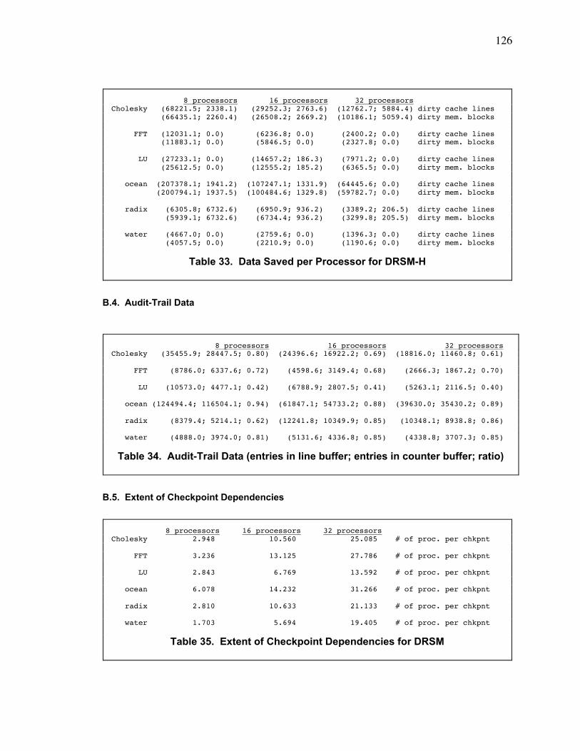
126
B.4. Audit-Trail Data
B.5. Extent of Checkpoint Dependencies
8 processors 16 processors 32 processorsCholesky (68221.5; 2338.1) (29252.3; 2763.6) (12762.7; 5884.4) dirty cache lines (66435.1; 2260.4) (26508.2; 2669.2) (10186.1; 5059.4) dirty mem. blocks
FFT (12031.1; 0.0) (6236.8; 0.0) (2400.2; 0.0) dirty cache lines (11883.1; 0.0) (5846.5; 0.0) (2327.8; 0.0) dirty mem. blocks
LU (27233.1; 0.0) (14657.2; 186.3) (7971.2; 0.0) dirty cache lines (25612.5; 0.0) (12555.2; 185.2) (6365.5; 0.0) dirty mem. blocks
ocean (207378.1; 1941.2) (107247.1; 1331.9) (64445.6; 0.0) dirty cache lines (200794.1; 1937.5) (100484.6; 1329.8) (59782.7; 0.0) dirty mem. blocks
radix (6305.8; 6732.6) (6950.9; 936.2) (3389.2; 206.5) dirty cache lines (5939.1; 6732.6) (6734.4; 936.2) (3299.8; 205.5) dirty mem. blocks
water (4667.0; 0.0) (2759.6; 0.0) (1396.3; 0.0) dirty cache lines (4057.5; 0.0) (2210.9; 0.0) (1190.6; 0.0) dirty mem. blocks
Table 33. Data Saved per Processor for DRSM-H
8 processors 16 processors 32 processorsCholesky (35455.9; 28447.5; 0.80) (24396.6; 16922.2; 0.69) (18816.0; 11460.8; 0.61)
FFT (8786.0; 6337.6; 0.72) (4598.6; 3149.4; 0.68) (2666.3; 1867.2; 0.70)
LU (10573.0; 4477.1; 0.42) (6788.9; 2807.5; 0.41) (5263.1; 2116.5; 0.40)
ocean (124494.4; 116504.1; 0.94) (61847.1; 54733.2; 0.88) (39630.0; 35430.2; 0.89)
radix (8379.4; 5214.1; 0.62) (12241.8; 10349.9; 0.85) (10348.1; 8938.8; 0.86)
water (4888.0; 3974.0; 0.81) (5131.6; 4336.8; 0.85) (4338.8; 3707.3; 0.85)
Table 34. Audit-Trail Data (entries in line buffer; entries in counter buffer; ratio)
8 processors 16 processors 32 processorsCholesky 2.948 10.560 25.085 # of proc. per chkpnt
FFT 3.236 13.125 27.786 # of proc. per chkpnt
LU 2.843 6.769 13.592 # of proc. per chkpnt
ocean 6.078 14.232 31.266 # of proc. per chkpnt
radix 2.810 10.633 21.133 # of proc. per chkpnt
water 1.703 5.694 19.405 # of proc. per chkpnt
Table 35. Extent of Checkpoint Dependencies for DRSM
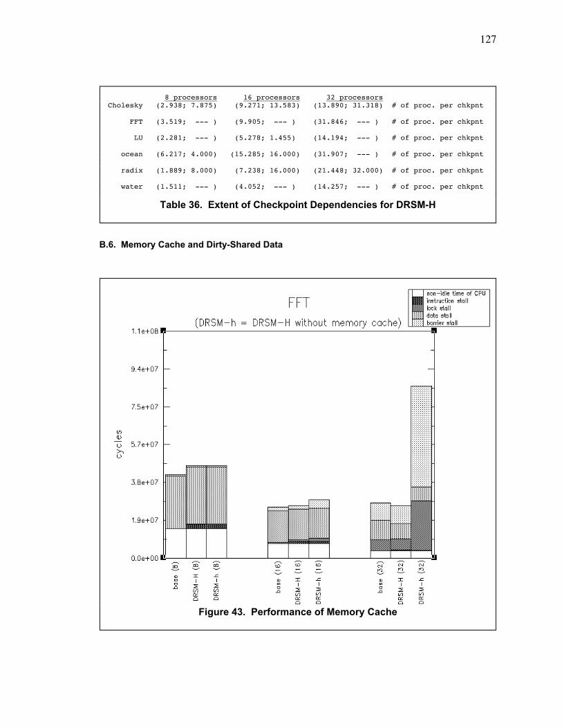
127
B.6. Memory Cache and Dirty-Shared Data
8 processors 16 processors 32 processorsCholesky (2.938; 7.875) (9.271; 13.583) (13.890; 31.318) # of proc. per chkpnt
FFT (3.519; --- ) (9.905; --- ) (31.846; --- ) # of proc. per chkpnt
LU (2.281; --- ) (5.278; 1.455) (14.194; --- ) # of proc. per chkpnt
ocean (6.217; 4.000) (15.285; 16.000) (31.907; --- ) # of proc. per chkpnt
radix (1.889; 8.000) (7.238; 16.000) (21.448; 32.000) # of proc. per chkpnt
water (1.511; --- ) (4.052; --- ) (14.257; --- ) # of proc. per chkpnt
Table 36. Extent of Checkpoint Dependencies for DRSM-H
Figure 43. Performance of Memory Cache
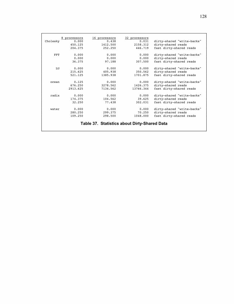
128
8 processors 16 processors 32 processorsCholesky 0.000 0.438 0.031 dirty-shared "write-backs" 450.125 1412.500 2158.312 dirty-shared reads 204.375 252.250 446.719 fast dirty-shared reads
FFT 0.000 0.000 0.000 dirty-shared "write-backs" 0.000 0.000 0.000 dirty-shared reads 36.375 97.188 307.500 fast dirty-shared reads
LU 0.000 0.000 0.000 dirty-shared "write-backs" 215.625 405.938 350.562 dirty-shared reads 521.125 1385.938 1701.875 fast dirty-shared reads
ocean 0.125 0.000 0.000 dirty-shared "write-backs" 676.250 3278.562 1426.375 dirty-shared reads 2913.625 7134.562 13766.344 fast dirty-shared reads
radix 0.000 0.000 0.000 dirty-shared "write-backs" 174.375 104.562 39.625 dirty-shared reads 32.250 77.438 302.031 fast dirty-shared reads
water 0.000 0.000 0.000 dirty-shared "write-backs" 280.250 299.375 70.250 dirty-shared reads 109.250 298.500 1048.000 fast dirty-shared reads
Table 37. Statistics about Dirty-Shared Data
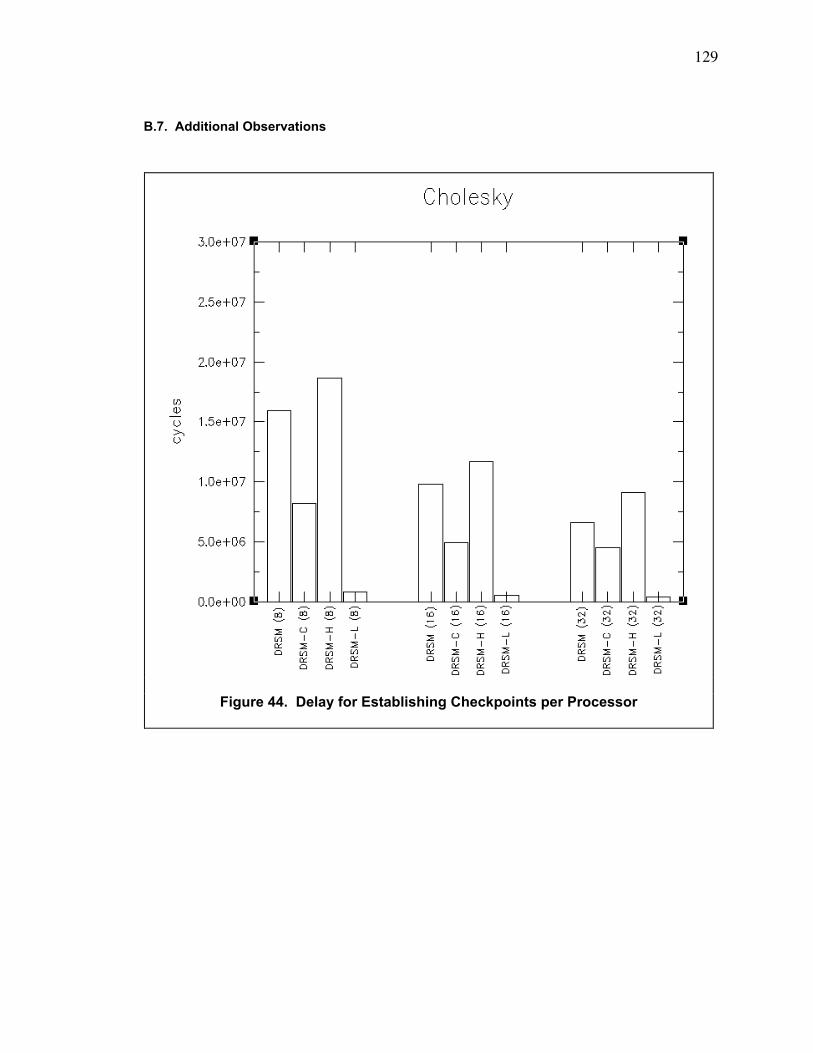
129
B.7. Additional Observations
Figure 44. Delay for Establishing Checkpoints per Processor
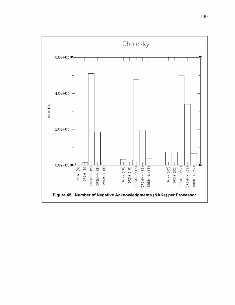
130
Figure 45. Number of Negative Acknowledgments (NAKs) per Processor
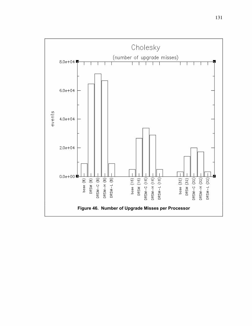
131
Figure 46. Number of Upgrade Misses per Processor
132
List of References
1. R. E. Ahmed, R. C. Frazier, et. al., "Cache-Aided Rollback Error Recovery (CARER)
Algorithms for Shared-Memory Multiprocessor Systems", Proceedings of the 20th International
Symposium on Fault-Tolerant Computing Systems, pp. 82-88, 1990.
2. M. Banatre, A. Gefflaut, et. al., "An Architecture for Tolerating Processor Failures in Shared-
Memory Multiprocessors", "IEEE Transactions on Computers", vol. 45, no. 10, pp. 1101-1115,
October 1996.
3. E. Bugnion, S. Devine, et. al., "Disco: running commodity operating systems on scalable
multiprocessors", "ACM Transactions on Computer Systems", vol. 15, no. 4, pp. 412-447,
November 1997.
4. S. Herrod, M. Rosenblum, et. al., "The SimOS Simulation Environment", Stanford University,
pp. 1-31, February 1997.
5. D. B. Hunt and P. N. Marinos, "A General Purpose Cache-Aided Rollback Error Recovery
(CARER) Technique", Proceedings of the 17th International Symposium on Fault-Tolerant
Computing Systems, pp. 170-175, 1987.
6. G. Janakiraman and Y. Tamir, ÒCoordinated Checkpointing-Rollback Error Recovery for
Distributed Shared Memory MulticomputersÓ, In Proceedings of the 13th Symposium on
Reliable Distributed Systems, pp. 42-51, October 1994.
7. B. Janssens and W. K. Fuchs, ÒThe Performance of Cache-Based Error Recovery in
MultiprocessorsÓ, ÒIEEE Transactions on Parallel and Distributed SystemsÓ, vol. 5, no. 10, pp.
1033-1043, October 1994.
8. G. J. Narlikar and G. E. Blelloch, ÒPthreads for Dynamic and Irregular ParallelismÓ,
Proceedings of Supercomputing 98: High Performance Networking and Computing, November
1998.
9. G. F. Pfister, In Search of Clusters, Prentice-Hall, Inc., Upper Saddle River, New Jersey,
1998.
10. G. Richard III and M. Singhal, "Using Logging and Asynchronous Checkpointing to Implement
Recoverable Distributed Shared Memory", Proceedings of the 12th Symposium on Reliable
Distributed Systems, pp. 58-67, October 1993.
11. T. J. Slegel, R. M. Averill III, et. al., ÒIBM S/390 G5 MicroprocessorÓ, ÒMicroÓ, vol. 19, no. 2,
March 1999.
133
12. D. Sunada, D. Glasco, M. Flynn, "ABSS v2.0: a SPARC Simulator", Proceedings of the
Eighth Workshop on Synthesis and System Integration of Mixed Technologies, pp. 143-149,
October 1998.
13. D. Sunada, D. Glasco, M. Flynn, "Hardware-assisted Algorithms for Checkpoints", technical
report: csl-tr-98-756, Stanford University, pp. 1-38, July 1998.
14. D. Sunada, D. Glasco, M. Flynn, "Novel Checkpointing Algorithm for Fault Tolerance on a
Tightly-Coupled Multiprocessor", technical report: csl-tr-99-776, Stanford University, pp. 1-50,
January 1999.
15. G. Suri, B. Janssens, et. al., "Reduced Overhead Logging for Rollback Recovery in
Distributed Shared Memory", Proceedings of the 25th International Symposium on Fault-
Tolerant Computing Systems, pp. 279-288, 1995.
16. S. C. Woo, M. Ohara, E. Torrie, J. Singh, A. Gupta, "The SPLASH-2 Programs:
Characterization and Methodological Considerations", Proceedings of the 22nd Annual
International Symposium on Computer Architecture, pp. 24-36, June 1995.
17. K. Wu, W. Fuchs, et. al., "Error Recovery in Shared Memory Multiprocessors Using Private
Caches", "IEEE Transactions on Parallel and Distributed Systems", vol. 1, no. 2, pp. 231-240,
April 1990.