Embed Size (px)
Citation preview

Check Point Safe@Office Internet Security Appliance
User Guide
Version 6.0
Part No: 700797, November 2005

COPYRIGHT & TRADEMARKS
Copyright © 2005 SofaWare, All Rights Reserved. No part of this document may be reproduced in any form or by any means without written permission from SofaWare. Information in this document is subject to change without notice and does not represent a commitment on part of SofaWare Technologies Ltd. SofaWare, Safe@Home and Safe@Office are trademarks, service marks, or registered trademarks of SofaWare Technologies Ltd. Check Point, the Check Point logo, FireWall-1, FireWall-1 SecureServer, FireWall-1 SmallOffice, FloodGate-1, INSPECT, IQ Engine, Meta IP, MultiGate, Open Security Extension, OPSEC, Provider-1, SecureKnowledge, SecureUpdate, SiteManager-1, SVN, UAM, User-to-Address Mapping, UserAuthority, Visual Policy Editor, VPN-1, VPN-1 Accelerator Card, VPN-1 Gateway, VPN-1 SecureClient, VPN-1 SecuRemote, VPN-1 SecureServer, and VPN-1 Edge are trademarks, service marks, or registered trademarks of Check Point Software Technologies Ltd. or its affiliates. All other product names mentioned herein are trademarks or registered trademarks of their respective owners. The products described in this document are protected by U.S. Patent No. 5,606,668 and 5,835,726 and may be protected by other U.S. Patents, foreign patents, or pending applications.
GNU GENERAL PUBLIC LICENSE
Version 2, June 1991 Copyright © 1989, 1991 Free Software Foundation, Inc. 59 Temple Place, Suite 330, Boston, MA 02111-1307 USA Everyone is permitted to copy and distribute verbatim copies of this license document, but changing it is not allowed. PREAMBLE The licenses for most software are designed to take away your freedom to share and change it. By contrast, the GNU General Public License is intended to guarantee your freedom to share and change free software--to make sure the software is free for all its users. This General Public License applies to most of the Free Software Foundation's software and to any other program whose authors commit to using it. (Some other Free Software Foundation software is covered by the GNU Library General Public License instead.) You can apply it to your programs, too. When we speak of free software, we are referring to freedom, not price. Our General Public Licenses are designed to make sure that you have the freedom to distribute copies of free software (and charge for this service if you wish), that you receive source code or can get it if you want it, that you can change the software or use pieces of it in new free programs; and that you know you can do these things. To protect your rights, we need to make restrictions that forbid anyone to deny you these rights or to ask you to surrender the rights. These restrictions translate to certain responsibilities for you if you distribute copies of the software, or if you modify it. For example, if you distribute copies of such a program, whether gratis or for a fee, you must give the recipients all the rights that you have. You must make sure that they, too, receive or can get the source code. And you must show them these terms so they know their rights.
We protect your rights with two steps: (1) copyright the software, and (2) offer you this license which gives you legal permission to copy, distribute and/or modify the software. Also, for each author's protection and ours, we want to make certain that everyone understands that there is no warranty for this free software. If the software is modified by someone else and passed on, we want its recipients to know that what they have is not the original, so that any problems introduced by others will not reflect on the original authors' reputations. Finally, any free program is threatened constantly by software patents. We wish to avoid the danger that redistributors of a free program will individually obtain patent licenses, in effect making the program proprietary. To prevent this, we have made it clear that any patent must be licensed for everyone's free use or not licensed at all. The precise terms and conditions for copying, distribution and modification follow. GNU GENERAL PUBLIC LICENSE TERMS AND CONDITIONS FOR COPYING, DISTRIBUTION AND MODIFICATION 0. This License applies to any program or other work which contains a notice placed by the copyright holder saying it may be distributed under the terms of this General Public License. The "Program", below, refers to any such program or work, and a "work based on the Program" means either the Program or any derivative work under copyright law: that is to say, a work containing the Program or a portion of it, either verbatim or with modifications and/or translated into another language. (Hereinafter, translation is included without limitation in the term "modification".) Each licensee is addressed as "you". Activities other than copying, distribution and modification are not covered by this License; they are outside its scope. The act of running the Program is not restricted, and the output from the Program is covered only if its contents constitute a work based on the Program (independent of having been made by running the Program). Whether that is true depends on what the Program does. 1. You may copy and distribute verbatim copies of the Program's source code as you receive it, in any medium, provided that you conspicuously and appropriately publish on each copy an appropriate copyright notice and disclaimer of warranty; keep intact all the notices that refer to this License and to the absence of any warranty; and give any other recipients of the Program a copy of this License along with the Program. You may charge a fee for the physical act of transferring a copy, and you may at your option offer warranty protection in exchange for a fee. 2. You may modify your copy or copies of the Program or any portion of it, thus forming a work based on the Program, and copy and distribute such modifications or work under the terms of Section 1 above, provided that you also meet all of these conditions:
a) You must cause the modified files to carry prominent notices stating that you changed the files and the date of any change.
b) You must cause any work that you distribute or publish, that in whole or in part contains or is derived from the Program or any part thereof, to be licensed as a whole at no charge to all third parties under the terms of this License.
c) If the modified program normally reads commands interactively when run, you must cause it, when started

running for such interactive use in the most ordinary way, to print or display an announcement including an appropriate copyright notice and a notice that there is no warranty (or else, saying that you provide a warranty) and that users may redistribute the program under these conditions, and telling the user how to view a copy of this License. (Exception: if the Program itself is interactive but does not normally print such an announcement, your work based on the Program is not required to print an announcement.)
These requirements apply to the modified work as a whole. If identifiable sections of that work are not derived from the Program, and can be reasonably considered independent and separate works in themselves, then this License, and its terms, do not apply to those sections when you distribute them as separate works. But when you distribute the same sections as part of a whole which is a work based on the Program, the distribution of the whole must be on the terms of this License, whose permissions for other licensees extend to the entire whole, and thus to each and every part regardless of who wrote it. Thus, it is not the intent of this section to claim rights or contest your rights to work written entirely by you; rather, the intent is to exercise the right to control the distribution of derivative or collective works based on the Program. In addition, mere aggregation of another work not based on the Program with the Program (or with a work based on the Program) on a volume of a storage or distribution medium does not bring the other work under the scope of this License. 3. You may copy and distribute the Program (or a work based on it, under Section 2) in object code or executable form under the terms of Sections 1 and 2 above provided that you also do one of the following:
a) Accompany it with the complete corresponding machine-readable source code, which must be distributed under the terms of Sections 1 and 2 above on a medium customarily used for software interchange; or,
b) Accompany it with a written offer, valid for at least three years, to give any third party, for a charge no more than your cost of physically performing source distribution, a complete machine-readable copy of the corresponding source code, to be distributed under the terms of Sections 1 and 2 above on a medium customarily used for software interchange; or,
c) Accompany it with the information you received as to the offer to distribute corresponding source code. (This alternative is allowed only for noncommercial distribution and only if you received the program in object code or executable form with such an offer, in accord with Subsection b above.)
The source code for a work means the preferred form of the work for making modifications to it. For an executable work, complete source code means all the source code for all modules it contains, plus any associated interface definition files, plus the scripts used to control compilation and installation of the executable. However, as a special exception, the source code distributed need not include anything that is normally distributed (in either source or binary form) with the major components (compiler, kernel, and so on) of the operating system on which the executable runs, unless that component itself accompanies the executable.
If distribution of executable or object code is made by offering access to copy from a designated place, then offering equivalent access to copy the source code from the same place counts as distribution of the source code, even though third parties are not compelled to copy the source along with the object code. 4. You may not copy, modify, sublicense, or distribute the Program except as expressly provided under this License. Any attempt otherwise to copy, modify, sublicense or distribute the Program is void, and will automatically terminate your rights under this License. However, parties who have received copies, or rights, from you under this License will not have their licenses terminated so long as such parties remain in full compliance. 5. You are not required to accept this License, since you have not signed it. However, nothing else grants you permission to modify or distribute the Program or its derivative works. These actions are prohibited by law if you do not accept this License. Therefore, by modifying or distributing the Program (or any work based on the Program), you indicate your acceptance of this License to do so, and all its terms and conditions for copying, distributing or modifying the Program or works based on it. 6. Each time you redistribute the Program (or any work based on the Program), the recipient automatically receives a license from the original licensor to copy, distribute or modify the Program subject to these terms and conditions. You may not impose any further restrictions on the recipients' exercise of the rights granted herein. You are not responsible for enforcing compliance by third parties to this License. 7. If, as a consequence of a court judgment or allegation of patent infringement or for any other reason (not limited to patent issues), conditions are imposed on you (whether by court order, agreement or otherwise) that contradict the conditions of this License, they do not excuse you from the conditions of this License. If you cannot distribute so as to satisfy simultaneously your obligations under this License and any other pertinent obligations, then as a consequence you may not distribute the Program at all. For example, if a patent license would not permit royalty-free redistribution of the Program by all those who receive copies directly or indirectly through you, then the only way you could satisfy both it and this License would be to refrain entirely from distribution of the Program. If any portion of this section is held invalid or unenforceable under any particular circumstance, the balance of the section is intended to apply and the section as a whole is intended to apply in other circumstances. It is not the purpose of this section to induce you to infringe any patents or other property right claims or to contest validity of any such claims; this section has the sole purpose of protecting the integrity of the free software distribution system, which is implemented by public license practices. Many people have made generous contributions to the wide range of software distributed through that system in reliance on consistent application of that system; it is up to the author/donor to decide if he or she is willing to distribute software through any other system and a licensee cannot impose that choice. This section is intended to make thoroughly clear what is believed to be a consequence of the rest of this License. 8. If the distribution and/or use of the Program is restricted in certain countries either by patents or by copyrighted interfaces, the original copyright holder who places the Program under this License may add an explicit geographical distribution limitation excluding those countries, so that distribution is permitted only in or among

countries not thus excluded. In such case, this License incorporates the limitation as if written in the body of this License. 9. The Free Software Foundation may publish revised and/or new versions of the General Public License from time to time. Such new versions will be similar in spirit to the present version, but may differ in detail to address new problems or concerns. Each version is given a distinguishing version number. If the Program specifies a version number of this License which applies to it and "any later version", you have the option of following the terms and conditions either of that version or of any later version published by the Free Software Foundation. If the Program does not specify a version number of this License, you may choose any version ever published by the Free Software Foundation. 10. If you wish to incorporate parts of the Program into other free programs whose distribution conditions are different, write to the author to ask for permission. For software which is copyrighted by the Free Software Foundation, write to the Free Software Foundation; we sometimes make exceptions for this. Our decision will be guided by the two goals of preserving the free status of all derivatives of our free software and of promoting the sharing and reuse of software generally. NO WARRANTY 11. BECAUSE THE PROGRAM IS LICENSED FREE OF CHARGE, THERE IS NO WARRANTY FOR THE PROGRAM, TO THE EXTENT PERMITTED BY APPLICABLE LAW. EXCEPT WHEN OTHERWISE STATED IN WRITING THE COPYRIGHT HOLDERS AND/OR OTHER PARTIES PROVIDE THE PROGRAM "AS IS" WITHOUT WARRANTY OF ANY KIND, EITHER EXPRESSED OR IMPLIED, INCLUDING, BUT NOT LIMITED TO, THE IMPLIED WARRANTIES OF MERCHANTABILITY AND FITNESS FOR A PARTICULAR PURPOSE. THE ENTIRE RISK AS TO THE QUALITY AND PERFORMANCE OF THE PROGRAM IS WITH YOU. SHOULD THE PROGRAM PROVE DEFECTIVE, YOU ASSUME THE COST OF ALL NECESSARY SERVICING, REPAIR OR CORRECTION. 12. IN NO EVENT UNLESS REQUIRED BY APPLICABLE LAW OR AGREED TO IN WRITING WILL ANY COPYRIGHT HOLDER, OR ANY OTHER PARTY WHO MAY MODIFY AND/OR REDISTRIBUTE THE PROGRAM AS PERMITTED ABOVE, BE LIABLE TO YOU FOR DAMAGES, INCLUDING ANY GENERAL, SPECIAL, INCIDENTAL OR CONSEQUENTIAL DAMAGES ARISING OUT OF THE USE OR INABILITY TO USE THE PROGRAM (INCLUDING BUT NOT LIMITED TO LOSS OF DATA OR DATA BEING RENDERED INACCURATE OR LOSSES SUSTAINED BY YOU OR THIRD PARTIES OR A FAILURE OF THE PROGRAM TO OPERATE WITH ANY OTHER PROGRAMS), EVEN IF SUCH HOLDER OR OTHER PARTY HAS BEEN ADVISED OF THE POSSIBILITY OF SUCH DAMAGES. To receive the SofaWare GPL licensed code, contact [email protected].
SAFETY PRECAUTIONS
Carefully read the Safety Instructions the Installation and Operating Procedures provided in this User's Guide before attempting to install or operate the appliance. Failure to follow these instructions may result in damage to equipment and/or personal injuries. Before cleaning the appliance, unplug the power cord. Use
only a soft cloth dampened with water for cleaning.
When installing the appliance, ensure that the vents are not blocked.
Do not place this product on an unstable surface or support. The product may fall, causing serious injury to a child or adult, as well as serious damage to the product.
Do not use the appliance outdoors. Do not expose the appliance to liquid or moisture. Do not expose the appliance to extreme high or low
temperatures. Do not disassemble or open the appliance. Failure to comply
will void the warranty. Do not use any accessories other than those approved by
Check Point. Failure to do so may result in loss of performance, damage to the product, fire, electric shock or injury, and will void the warranty.
Route power supply cords where they are not likely to be walked on or pinched by items placed on or against them. Pay particular attention to cords where they are attached to plugs and convenience receptacles, and examine the point where they exit the unit.
Do not connect or disconnect power supply cables and data transmission lines during thunderstorms.
Do not overload wall outlets or extension cords, as this can result in a risk of fire or electric shock. Overloaded AC outlets, extension cords, frayed power cords, damaged or cracked wire insulation, and broken plugs are dangerous. They may result in a shock or fire hazard. Periodically examine the cord, and if its appearance indicates damage or deteriorated insulation, have it replaced by your service technician.
If the unit or any part of it is damaged, disconnect the power plug and inform the responsible service personnel. Non-observance may result in damage to the router.
POWER ADAPTER
Operate this product only from the type of power source indicated on the product’s marking label. If you are not sure of the type of power supplied to your home, consult your dealer or local power company.
Use only the power supply provided with your product. Check whether the device’s set supply voltage is the same as the local supply voltage.
To reduce risk of damage to the unit, remove it from the outlet by holding the power adapter rather than the cord.
SECURITY DISCLAIMER
The appliance provides your office network with the highest level of security. However, no single security product can provide you with absolute protection against a determined effort to break into your system. We recommend using additional security measures to secure highly valuable or sensitive information.

Contents
Contents i
Contents About This Guide.................................................................................................................................xi Chapter 1: Introduction .......................................................................................................................1
About Your Check Point Safe@Office Appliance..............................................................................1 Safe@Office 500 Product Family .......................................................................................................2 Safe@Office Features and Compatibility ...........................................................................................2
Connectivity....................................................................................................................................2 Firewall ...........................................................................................................................................3 VPN ................................................................................................................................................4 Management....................................................................................................................................4 Optional Security Services..............................................................................................................5 Power Pack Features .......................................................................................................................5 Package Contents ............................................................................................................................6 Network Requirements ...................................................................................................................7
Getting to Know Your Safe@Office 500 Appliance...........................................................................8 Rear Panel .......................................................................................................................................8 Front Panel ....................................................................................................................................10
Getting to Know Your Safe@Office 500W Appliance.....................................................................11 Rear Panel .....................................................................................................................................11 Front Panel ....................................................................................................................................13
Contacting Technical Support...........................................................................................................14 Chapter 2: Installing and Setting up the Safe@Office Appliance ..................................................15
Before You Install the Safe@Office Appliance ................................................................................15 Windows 2000/XP ........................................................................................................................16 Windows 98/Millennium ..............................................................................................................21 Mac OS .........................................................................................................................................26 Mac OS-X .....................................................................................................................................28

Contents
ii Check Point Safe@Office User Guide
Wall Mounting the Appliance...........................................................................................................30 Securing the Appliance against Theft ...............................................................................................32 Network Installation..........................................................................................................................35 Setting Up the Safe@Office Appliance ............................................................................................36
Chapter 3: Getting Started.................................................................................................................39 Initial Login to the Safe@Office Portal ............................................................................................39 Logging on to the Safe@Office Portal..............................................................................................42 Accessing the Safe@Office Portal Remotely Using HTTPS............................................................44 Using the Safe@Office Portal...........................................................................................................46
Main Menu....................................................................................................................................47 Main Frame...................................................................................................................................48 Status Bar ......................................................................................................................................48
Logging off .......................................................................................................................................51 Chapter 4: Configuring the Internet Connection.............................................................................53
Overview...........................................................................................................................................53 Using the Internet Wizard .................................................................................................................54
Using a Direct LAN Connection...................................................................................................56 Using a Cable Modem Connection ...............................................................................................58 Using a PPTP or PPPoE Dialer Connection..................................................................................59 Using PPPoE.................................................................................................................................60 Using PPTP...................................................................................................................................61
Using Internet Setup..........................................................................................................................63 Using a LAN Connection..............................................................................................................65 Using a Cable Modem Connection ...............................................................................................67 Using a PPPoE Connection...........................................................................................................69 Using a PPTP Connection.............................................................................................................71 Using a Telstra (BPA) Connection ...............................................................................................73

Contents
Contents iii
Using a Dialup Connection ...........................................................................................................75 Using No Connection....................................................................................................................77
Setting Up a Dialup Modem .............................................................................................................84 Viewing Internet Connection Information ........................................................................................87 Enabling/Disabling the Internet Connection .....................................................................................88 Using Quick Internet Connection/Disconnection..............................................................................90 Configuring a Backup Internet Connection.......................................................................................90
Setting Up a LAN or Broadband Backup Connection ..................................................................91 Setting Up a Dialup Backup Connection ......................................................................................92
Chapter 5: Managing Your Network ................................................................................................93 Configuring Network Settings ..........................................................................................................93
Configuring a DHCP Server .........................................................................................................94 Changing IP Addresses ...............................................................................................................105 Enabling/Disabling Hide NAT....................................................................................................107 Configuring a DMZ Network......................................................................................................108 Configuring the OfficeMode Network........................................................................................110 Configuring VLANs ...................................................................................................................111
Configuring High Availability ........................................................................................................119 Configuring High Availability on a Gateway .............................................................................122 Sample Implementation on Two Gateways.................................................................................126 Adding and Editing Network Objects .........................................................................................130 Viewing and Deleting Network Objects .....................................................................................138
Using Static Routes.........................................................................................................................139 Adding and Editing Static Routes ...............................................................................................139 Viewing and Deleting Static Routes ...........................................................................................144
Managing Ports ...............................................................................................................................145 Viewing Port Statuses .................................................................................................................146

Contents
iv Check Point Safe@Office User Guide
Modifying Port Assignments ......................................................................................................147 Modifying Link Configurations ..................................................................................................149 Resetting Ports to Defaults..........................................................................................................150
Chapter 6: Using Traffic Shaper .....................................................................................................151 Overview.........................................................................................................................................151 Setting Up Traffic Shaper ...............................................................................................................153 Predefined QoS Classes ..................................................................................................................154 Adding and Editing Classes ............................................................................................................155 Deleting Classes..............................................................................................................................159 Restoring Traffic Shaper Defaults...................................................................................................160
Chapter 7: Configuring a Wireless Network ..................................................................................161 Overview.........................................................................................................................................161 About the Wireless Hardware in Your Safe@Office 500W Appliance ..........................................162 Wireless Security Protocols ............................................................................................................163 Manually Configuring a WLAN .....................................................................................................165 Using the Wireless Configuration Wizard ......................................................................................176
WPA-PSK...................................................................................................................................178 WEP............................................................................................................................................180 No Security .................................................................................................................................181
Preparing the Wireless Stations.......................................................................................................182 Troubleshooting Wireless Connectivity..........................................................................................183
Chapter 8: Viewing Reports.............................................................................................................187 Viewing the Event Log ...................................................................................................................187 Using the Traffic Monitor ...............................................................................................................191
Viewing Traffic Reports .............................................................................................................191 Configuring Traffic Monitor Settings .........................................................................................193 Exporting General Traffic Reports..............................................................................................194

Contents
Contents v
Viewing Computers ........................................................................................................................194 Viewing Connections ......................................................................................................................197 Viewing Wireless Statistics.............................................................................................................198
Chapter 9: Setting Your Security Policy.........................................................................................203 Default Security Policy ...................................................................................................................203 Setting the Firewall Security Level.................................................................................................204 Configuring Servers ........................................................................................................................207 Using Rules .....................................................................................................................................209
Adding and Editing Rules ...........................................................................................................213 Enabling/Disabling Rules ...........................................................................................................218 Changing Rules' Priority .............................................................................................................219 Deleting Rules.............................................................................................................................219
Using SmartDefense .......................................................................................................................220 Configuring SmartDefense..........................................................................................................221 SmartDefense Categories............................................................................................................224
Using Secure HotSpot .....................................................................................................................256 Setting Up Secure HotSpot .........................................................................................................257 Enabling/Disabling Secure HotSpot............................................................................................258 Customizing Secure HotSpot ......................................................................................................259
Defining an Exposed Host ..............................................................................................................261 Chapter 10: Using VStream Antivirus ............................................................................................263
Overview.........................................................................................................................................263 Enabling/Disabling VStream Antivirus...........................................................................................265 Viewing VStream Signature Database Information ........................................................................266 Configuring VStream Antivirus ......................................................................................................267
Configuring the VStream Antivirus Policy.................................................................................267 Configuring VStream Advanced Settings ...................................................................................275

Contents
vi Check Point Safe@Office User Guide
Updating VStream Antivirus...........................................................................................................279 Chapter 11: Using Subscription Services........................................................................................281
Connecting to a Service Center.......................................................................................................281 Viewing Services Information ........................................................................................................287 Refreshing Your Service Center Connection ..................................................................................288 Configuring Your Account .............................................................................................................288 Disconnecting from Your Service Center .......................................................................................289 Web Filtering ..................................................................................................................................290
Enabling/Disabling Web Filtering ..............................................................................................290 Selecting Categories for Blocking ..............................................................................................291 Temporarily Disabling Web Filtering .........................................................................................292
Email Filtering ................................................................................................................................294 Enabling/Disabling Email Filtering ............................................................................................295 Selecting Protocols for Scanning ................................................................................................296 Temporarily Disabling Email Filtering .......................................................................................296
Automatic and Manual Updates......................................................................................................298 Checking for Software Updates when Remotely Managed ........................................................298 Checking for Software Updates when Locally Managed............................................................299
Chapter 12: Working With VPNs ...................................................................................................301 Overview.........................................................................................................................................301
Site-to-Site VPNs........................................................................................................................302 Remote Access VPNs .................................................................................................................305 Internal VPN Server....................................................................................................................306
Setting Up Your Safe@Office Appliance as a VPN Server............................................................307 Configuring the Remote Access VPN Server .............................................................................309 Configuring the Internal VPN Server..........................................................................................310 Installing SecuRemote ................................................................................................................311

Contents
Contents vii
Adding and Editing VPN Sites .......................................................................................................312 Configuring a Remote Access VPN Site.....................................................................................314 Configuring a Site-to-Site VPN Gateway ...................................................................................327
Deleting a VPN Site ........................................................................................................................343 Enabling/Disabling a VPN Site.......................................................................................................343 Logging on to a Remote Access VPN Site......................................................................................344
Logging on through the Safe@Office Portal ..............................................................................345 Logging on through the my.vpn page .........................................................................................346
Logging off a Remote Access VPN Site .........................................................................................348 Installing a Certificate .....................................................................................................................348
Generating a Self-Signed Certificate...........................................................................................349 Importing a Certificate ................................................................................................................353
Uninstalling a Certificate ................................................................................................................355 Viewing VPN Tunnels ....................................................................................................................356 Viewing IKE Traces for VPN Connections ....................................................................................359
Chapter 13: Managing Users ...........................................................................................................361 Changing Your Password................................................................................................................361 Adding and Editing Users ...............................................................................................................363 Adding Quick Guest HotSpot Users ...............................................................................................367 Viewing and Deleting Users ...........................................................................................................369 Setting Up Remote VPN Access for Users .....................................................................................369 Using RADIUS Authentication.......................................................................................................370 Configuring the RADIUS Vendor-Specific Attribute.....................................................................374
Chapter 14: Maintenance.................................................................................................................377 Viewing Firmware Status................................................................................................................377 Updating the Firmware ...................................................................................................................379 Upgrading Your Software Product..................................................................................................381

Contents
viii Check Point Safe@Office User Guide
Registering Your Safe@Office Appliance......................................................................................385 Configuring Syslog Logging...........................................................................................................386 Controlling the Appliance via the Command Line..........................................................................388
Using the Safe@Office Portal.....................................................................................................388 Using the Serial Console.............................................................................................................390
Configuring HTTPS........................................................................................................................392 Configuring SSH.............................................................................................................................394 Configuring SNMP .........................................................................................................................396 Setting the Time on the Appliance..................................................................................................399 Using Diagnostic Tools...................................................................................................................403
Using IP Tools ............................................................................................................................404 Using Packet Sniffer ...................................................................................................................406 Filter String Syntax .....................................................................................................................409
Backing Up the Safe@Office Appliance Configuration .................................................................417 Exporting the Safe@Office Appliance Configuration ................................................................417 Importing the Safe@Office Appliance Configuration ................................................................418
Resetting the Safe@Office Appliance to Defaults ..........................................................................420 Running Diagnostics .......................................................................................................................423 Rebooting the Safe@Office Appliance...........................................................................................424
Chapter 15: Using Network Printers...............................................................................................425 Overview.........................................................................................................................................425 Setting Up Network Printers ...........................................................................................................426 Configuring Computers to Use Network Printers ...........................................................................427
Windows 2000/XP ......................................................................................................................427 MAC OS-X .................................................................................................................................433
Viewing Network Printers...............................................................................................................437 Changing Network Printer Ports .....................................................................................................437

Contents
Contents ix
Resetting Network Printers .............................................................................................................438 Chapter 16: Troubleshooting ...........................................................................................................439
Connectivity ....................................................................................................................................440 Service Center and Upgrades ..........................................................................................................444 Other Problems ...............................................................................................................................445
Chapter 17: Specifications................................................................................................................447 Technical Specifications .................................................................................................................447 CE Declaration of Conformity ........................................................................................................451 Federal Communications Commission Radio Frequency Interference Statement ..........................453
Glossary of Terms .............................................................................................................................455 Index...................................................................................................................................................463


About Your Check Point Safe@Office Appliance
Chapter 1: About This Guide xi
To make finding information in this manual easier, some types of information are marked with special symbols or formatting.
Boldface type is used for command and button names.
Note: Notes are denoted by indented text and preceded by the Note icon.
Warning: Warnings are denoted by indented text and preceded by the Warning icon.
Each task is marked with an icon indicating the Safe@Office product required to perform the task, as follows:
If this icon appears... You can perform the task using these products...
Safe@Office 500 or Safe@Office 500W, with or without the Power
Pack
Safe@Office 500W only, with or without the Power Pack
Safe@Office 500 or Safe@Office 500W, with the Power Pack only
About This Guide


About Your Check Point Safe@Office Appliance
Chapter 1: Introduction 1
Chapter 1
This chapter introduces the Check Point Safe@Office appliance and this guide.
This chapter includes the following topics: About Your Check Point Safe@Office Appliance .......................................1 Safe@Office 500 Product Family ................................................................2 Safe@Office Features and Compatibility.....................................................2 Getting to Know Your Safe@Office 500 Appliance....................................8 Getting to Know Your Safe@Office 500W Appliance ..............................11 Contacting Technical Support ....................................................................14
About Your Check Point Safe@Office Appliance The Check Point Safe@Office 500 appliance is a unified threat management (UTM) appliance that enables secure high-speed Internet access from the office. Developed and supported by SofaWare Technologies, an affiliate of Check Point Software Technologies, the worldwide leader in securing the Internet, the Safe@Office 500 product family includes both wired and wireless models. The Safe@Office firewall, based on the world-leading Check Point Embedded NGX Stateful Inspection technology, inspects and filters all incoming and outgoing traffic, blocking all unauthorized traffic.
The Safe@Office appliance also allows sharing your Internet connection among several PCs or other network devices, enabling advanced office networking and saving the cost of purchasing static IP addresses.
With the Safe@Office appliance, you can subscribe to additional security services available from select service providers, including firewall security and software updates, Antivirus, Web Filtering, reporting, VPN management, and Dynamic DNS. By supporting integrated VPN capabilities, the Safe@Office appliance allows teleworkers and road warriors to securely connect to the office network, and enables secure interconnection of branch offices.
Introduction

Safe@Office 500 Product Family
2 Check Point Safe@Office User Guide
Safe@Office 500 Product Family The Safe@Office 500 series includes the following hardware models:
• Safe@Office 500 Internet Security Appliance
• Safe@Office 500W Wireless Security Appliance
You can upgrade your Safe@Office appliance to include additional features without replacing the hardware by installing the Safe@Office 500 Power Pack, and you can increase the number of licensed users by installing node upgrades. Contact your reseller for more details.
Safe@Office Features and Compatibility Connectivity
The Safe@Office 500 series includes the following features:
• LAN ports: 4-ports 10/100 Mbps Fast Ethernet switch
• WAN port: 10/100 Mbps Fast Ethernet
• DMZ/WAN2 Port: 10/100 Mbps Fast Ethernet
• Serial (RS232) port for console access and dialup modem connection
• Supported Internet connection methods: Static IP, DHCP Client, Cable Modem, PPTP Client, PPPoE Client, Telstra BPA login, Dialup
• Concurrent firewall connections: 8,000
• DHCP server, client, and relay
• MAC cloning

Safe@Office Features and Compatibility
Chapter 1: Introduction 3
• Static NAT
• Static routes and source routes
• Ethernet cable type recognition
• Backup Internet connection
• Dead Internet Connection Detection (DCD)
• Traffic Monitoring
• Traffic Shaping
• VLAN Support (requires Power Pack)
• Dynamic Routing (requires Power Pack)
The Safe@Office 500W includes the following additional features:
• Wireless LAN interface with dual diversity antennas supporting up to 108 Mbps (Super G) and Extended Range (XR)
• Integrated USB print server
• Wireless QoS (WMM)
Firewall The Safe@Office 500 series includes the following features:
• Check Point Firewall-1 Embedded NGX firewall with Application Intelligence
• Intrusion Detection and Prevention using Check Point SmartDefense
• Network Address Translation (NAT)
• Three preset security policies
• Anti-spoofing
• Voice over IP (H.323) support
• Instant messenger blocking/monitoring

Safe@Office Features and Compatibility
4 Check Point Safe@Office User Guide
• P2P file sharing blocking/monitoring
VPN The Safe@Office 500 series includes the following features:
• Remote Access VPN Server with OfficeMode and RADIUS support
• Remote Access VPN Client
• Site to Site VPN Gateway
• IPSEC VPN pass-through
• Algorithms: AES/3DES/DES, SHA1/MD5
• Hardware Based Secure RNG (Random Number Generator)
• IPSec NAT traversal (NAT-T)
• Route-based VPN
• Backup VPN gateways
Management The Safe@Office 500 series includes the following features:
• Management via HTTP, HTTPS, SSH, SNMP, Serial CLI
• Central Management: SMP
• NTP automatic time setting
• TFTP Rapid Deployment
• Local diagnostics tools: Ping, WHOIS, Packet Sniffer, VPN Tunnel Monitor, Connection Table Monitor, Wireless Monitor, Active Computers Display, Local Logs

Safe@Office Features and Compatibility
Chapter 1: Introduction 5
Optional Security Services The following subscription security services are available to Safe@Office owners by connecting to a Service Center:
• Firewall Security and Software Updates
• Web Filtering
• Email Antivirus and Antispam Protection
• VStream Embedded Antivirus Updates
• Dynamic DNS Service
• VPN Management
• Security Reporting
• Vulnerability Scanning Service
Power Pack Features The table below describes the differences between the standard Safe@Office 500 models and Safe@Office 500 models with the Power Pack installed.
Feature Safe@Office 500/500W Safe@Office 500/500W with
Power Pack
High Availability —
Traffic Shaper Basic Advanced
DiffServ Tagging —
Dynamic Routing —
Firewall/VPN Throughput
(Mbps) 100/20 150/30

Safe@Office Features and Compatibility
6 Check Point Safe@Office User Guide
Feature Safe@Office 500/500W Safe@Office 500/500W with
Power Pack
Secure Hotspot —
VLAN (Port/Tag-based) —
VPN Throughput 20 Mbps 30 Mbps
Site-to-Site VPN 2 tunnels 15 tunnels
Site-to-Site VPN
(Managed) * 10 tunnels 100 tunnels
Included VPN-1
SecuRemote client
Licenses
5 users 25 users
* When managed by SofaWare Security Management Portal (SMP).
Package Contents The Safe@Office 500 series package includes the following:
• Safe@Office Internet Security Appliance
• Power adapter
• CAT5 Straight-through Ethernet cable
• Getting Started Guide
• This Users Guide

Safe@Office Features and Compatibility
Chapter 1: Introduction 7
The Safe@Office 500W also includes:
• Two antennas
• Wall mounting kit, including two plastic conical anchors and two cross-head screws
• USB extension cable
Network Requirements • A broadband Internet connection via cable or DSL modem with Ethernet
interface (RJ-45)
• 10BaseT or 100BaseT Network Interface Card installed on each computer
• TCP/IP network protocol installed on each computer
• Internet Explorer 5.0 or higher, or Netscape Navigator 4.7 and higher
• CAT 5 STP (Category 5 Shielded Twisted Pair) Straight Through Ethernet cable for each attached device
Note: The Safe@Office appliance automatically detects cable types, so you can use either a straight-through or crossed cable, when cascading an additional hub or switch to the Safe@Office appliance.
Note: For optimal results, it is highly recommended to use either Microsoft Internet Explorer 5.5 or higher, or Mozilla Firefox 1.0 or higher.
• When using Safe@Office 500W, an 802.11b, 802.11g or 802.11 Super G
wireless card installed on each wireless station

Getting to Know Your Safe@Office 500 Appliance
8 Check Point Safe@Office User Guide
Getting to Know Your Safe@Office 500 Appliance
Rear Panel All physical connections (network and power) to the Safe@Office appliance are made via the rear panel of your Safe@Office appliance.
Figure 1: Safe@Office 500 SBX-166LHGE-2 Appliance Rear Panel Items
Figure 2: Safe@Office 500 SBX-166LHGE-4 Appliance Rear Panel Items
The following table lists the Safe@Office 500 appliance's rear panel elements.
Table 1: Safe@Office 500 Appliance Rear Panel Elements
Label Description
PWR A power jack used for supplying power to the unit. Connect the supplied power
adapter to this jack.

Getting to Know Your Safe@Office 500 Appliance
Chapter 1: Introduction 9
Label Description
RESET A button used for rebooting the Safe@Office appliance or resetting the
Safe@Office appliance to its factory defaults. You need to use a pointed object to
press this button.
• Short press. Reboots the Safe@Office appliance • Long press (7 seconds). Resets the Safe@Office appliance to its factory
defaults, and resets your firmware to the version that shipped with the Safe@Office appliance. This results in the loss of all security services and passwords and reverting to the factory default firmware. You will have to re-configure your Safe@Office appliance.
Do not reset the unit without consulting your system administrator.
RS-232 /
Serial
A serial port used for connecting computers in order to access the Safe@Office
CLI (Command Line Interface), or for connecting an external dialup modem
WAN Wide Area Network: An Ethernet port (RJ-45) used for connecting your cable or
xDSL modem, or for connecting a hub when setting up more than one Internet
connection
DMZ/
WAN2
A dedicated Ethernet port (RJ-45) used to connect a DMZ (Demilitarized Zone)
computer or network. Alternatively, can serve as a secondary WAN port , or as a
VLAN trunk.
LAN 1-4 Local Area Network switch: Four Ethernet ports (RJ-45) used for connecting
computers or other network devices


Getting to Know Your Safe@Office 500W Appliance
Chapter 1: Introduction 11
LED State Explanation
LINK/ACT On, 100 On 100 Mbps link established for the
corresponding port
LNK/ACT Flashing Data is being transmitted/received
VPN Flashing (Green) VPN port in use
Serial Flashing (Green) Serial port in use
Getting to Know Your Safe@Office 500W Appliance
Rear Panel All physical connections (network and power) to the Safe@Office appliance are made via the rear panel of your Safe@Office appliance.
Figure 4: Safe@Office 500W Appliance Rear Panel Items
The following table lists the Safe@Office 500W appliance's rear panel elements.
Table 3: Safe@Office 500W Appliance Rear Panel Elements
Label Description
PWR A power jack used for supplying power to the unit. Connect the supplied power
adapter to this jack.

Getting to Know Your Safe@Office 500W Appliance
12 Check Point Safe@Office User Guide
Label Description
RESET A button used for rebooting the Safe@Office appliance or resetting the
Safe@Office appliance to its factory defaults. You need to use a pointed object to
press this button.
• Short press. Reboots the Safe@Office appliance • Long press (7 seconds). Resets the Safe@Office appliance to its factory
defaults, and resets your firmware to the version that shipped with the Safe@Office appliance. This results in the loss of all security services and passwords and reverting to the factory default firmware. You will have to re-configure your Safe@Office appliance.
Do not reset the unit without consulting your system administrator.
USB Two USB 2.0 ports used for connecting USB-based printers
RS232 A serial (RS-232) port used for connecting computers in order to access the
Safe@Office CLI (Command Line Interface), or for connecting an external dialup
modem
WAN Wide Area Network: An Ethernet port (RJ-45) used for connecting your cable or
xDSL modem, or for connecting a hub when setting up more than one Internet
connection
DMZ/
WAN2
A dedicated Ethernet port (RJ-45) used to connect a DMZ (Demilitarized Zone)
computer or network. Alternatively, can serve as a secondary WAN port , or as a
VLAN trunk.
LAN 1-4 Local Area Network switch: Four Ethernet ports (RJ-45) used for connecting
computers or other network devices
ANT 1/
ANT 2
Antenna connectors, used to connect the supplied wireless antennas

Getting to Know Your Safe@Office 500W Appliance
Chapter 1: Introduction 13
Front Panel The Safe@Office 500W appliance includes several status LEDs that enable you to monitor the appliance’s operation.
Figure 5: Safe@Office 500W Appliance Front Panel
For an explanation of the Safe@Office 500W appliance’s status LEDs, see the table below.
Table 4: Safe@Office 500W Appliance Status LEDs
LED State Explanation
PWR/SEC Off Power off
Flashing quickly (Green) System boot-up
Flashing slowly (Green) Establishing Internet connection
On (Green) Normal operation
Flashing (Red) Hacker attack blocked
On (Red) Error
Flashing (Orange) Software update in progress
LAN 1-4/
WAN/
DMZ/WAN2
LINK/ACT Off, 100 Off Link is down
LINK/ACT On, 100 Off 10 Mbps link established for the
corresponding port

Contacting Technical Support
14 Check Point Safe@Office User Guide
LED State Explanation
LINK/ACT On, 100 On 100 Mbps link established for the
corresponding port
LNK/ACT Flashing Data is being transmitted/received
VPN Flashing (Green) VPN port in use
Serial Flashing (Green) Serial port in use
USB Flashing (Green) USB port in use
WLAN Flashing (Green) WLAN in use
Contacting Technical Support If there is a problem with your Safe@Office appliance, see http://www.sofaware.com/support.
You can also download the latest version of this guide from the site.

Before You Install the Safe@Office Appliance
Chapter 2: Installing and Setting up the Safe@Office Appliance 15
Chapter 2
This chapter describes how to properly set up and install your Safe@Office appliance in your networking environment.
This chapter includes the following topics: Before You Install the Safe@Office Appliance .........................................15 Wall Mounting the Appliance ....................................................................30 Securing the Appliance against Theft.........................................................32 Network Installation ...................................................................................35 Setting Up the Safe@Office Appliance......................................................36
Before You Install the Safe@Office Appliance Prior to connecting and setting up your Safe@Office appliance for operation, you must do the following:
• Check if TCP/IP Protocol is installed on your computer.
• Check your computer’s TCP/IP settings to make sure it obtains its IP address automatically.
Refer to the relevant section in this guide in accordance with the operating system that runs on your computer. The sections below will guide you through the TCP/IP setup and installation process.
Installing and Setting up the Safe@Office Appliance

Before You Install the Safe@Office Appliance
16 Check Point Safe@Office User Guide
Windows 2000/XP
Note: While Windows XP has an "Internet Connection Firewall" option, it is recommended to disable it if you are using a Safe@Office appliance, since the Safe@Office appliance offers better protection.
Checking the TCP/IP Installation 1. Click Start > Settings > Control Panel.
The Control Panel window appears.
2. Double-click the Network and Dial-up Connections icon.

Before You Install the Safe@Office Appliance
Chapter 2: Installing and Setting up the Safe@Office Appliance 17
The Network and Dial-up Connections window appears.
3. Right-click the icon and select Properties from the pop-up menu that opens.

Before You Install the Safe@Office Appliance
18 Check Point Safe@Office User Guide
The Local Area Connection Properties window appears.
4. In the above window, check if TCP/IP appears in the components list and if it is
properly configured with the Ethernet card, installed on your computer. If TCP/IP does not appear in the Components list, you must install it as described in the next section.
Before You Install the Safe@Office Appliance
Chapter 2: Installing and Setting up the Safe@Office Appliance 19
Installing TCP/IP Protocol 1. In the Local Area Connection Properties window click Install….
The Select Network Component Type window appears.
2. Choose Protocol and click Add.
The Select Network Protocol window appears.
3. Choose Internet Protocol (TCP/IP) and click OK.
TCP/IP protocol is installed on your computer.

Before You Install the Safe@Office Appliance
20 Check Point Safe@Office User Guide
TCP/IP Settings 1. In the Local Area Connection Properties window double-click the Internet
Protocol (TCP/IP) component, or select it and click Properties.
The Internet Protocol (TCP/IP) Properties window opens.
2. Click the Obtain an IP address automatically radio button.
Note: Normally, it is not recommended to assign a static IP address to your PC but rather to obtain an IP address automatically. If for some reason you need to assign a static IP address, select Specify an IP address, type in an IP address in the range of 192.168.10.129-254, enter 255.255.255.0 in the Subnet Mask field, and click OK to save the new settings.
(Note that 192.168.10 is the default value, and it may vary if you changed it in the My Network page.)
3. Click the Obtain DNS server address automatically radio button.
4. Click OK to save the new settings.
Your computer is now ready to access your Safe@Office appliance.

Before You Install the Safe@Office Appliance
Chapter 2: Installing and Setting up the Safe@Office Appliance 21
Windows 98/Millennium
Checking the TCP/IP Installation 1. Click Start > Settings > Control Panel.
The Control Panel window appears.
2. Double-click the icon.

Before You Install the Safe@Office Appliance
22 Check Point Safe@Office User Guide
The Network window appears.
3. In the Network window, check if TCP/IP appears in the network components list
and if it is already configured with the Ethernet card, installed on your computer.
Installing TCP/IP Protocol
Note: If TCP/IP is already installed and configured on your computer skip this section and move directly to TCP/IP Settings.
1. In the Network window, click Add.

Before You Install the Safe@Office Appliance
Chapter 2: Installing and Setting up the Safe@Office Appliance 23
The Select Network Component Type window appears.
2. Choose Protocol and click Add.
The Select Network Protocol window appears.
3. In the Manufacturers list choose Microsoft, and in the Network Protocols list
choose TCP/IP.
4. Click OK.
If Windows asks for original Windows installation files, provide the installation CD and relevant path when required (e.g. D:\win98)
5. Restart your computer if prompted.

Before You Install the Safe@Office Appliance
24 Check Point Safe@Office User Guide
TCP/IP Settings
Note: If you are connecting your Safe@Office appliance to an existing LAN, consult your network manager for the correct configurations.
1. In the Network window, double-click the TCP/IP service for the Ethernet card, which has been installed on your computer (e.g. ). The TCP/IP Properties window opens.
2. Click the Gateway tab, and remove any installed gateways.

Before You Install the Safe@Office Appliance
Chapter 2: Installing and Setting up the Safe@Office Appliance 25
3. Click the DNS Configuration tab, and click the Disable DNS radio button.

Before You Install the Safe@Office Appliance
26 Check Point Safe@Office User Guide
4. Click the IP Address tab, and click the Obtain an IP address automatically radio button.
Note: Normally, it is not recommended to assign a static IP address to your PC but rather to obtain an IP address automatically. If for some reason you need to assign a static IP address, select Specify an IP address, type in an IP address in the range of 192.168.10.129-254, enter 255.255.255.0 in the Subnet Mask field, and click OK to save the new settings.
(Note that 192.168.10 is the default value, and it may vary if you changed it in the My Network page.)
5. Click Yes when prompted for “Do you want to restart your computer?”.
Your computer restarts, and the new settings to take effect.
Your computer is now ready to access your Safe@Office appliance.
Mac OS Use the following procedure for setting up the TCP/IP Protocol.

Before You Install the Safe@Office Appliance
Chapter 2: Installing and Setting up the Safe@Office Appliance 27
1. Choose Apple Menus -> Control Panels -> TCP/IP.
The TCP/IP window appears.
2. Click the Connect via drop-down list, and select Ethernet. 3. Click the Configure drop-down list, and select Using DHCP Server. 4. Close the window and save the setup.

Before You Install the Safe@Office Appliance
28 Check Point Safe@Office User Guide
Mac OS-X Use the following procedure for setting up the TCP/IP Protocol.
1. Choose Apple -> System Preferences.
The System Preferences window appears.
2. Click Network.
The Network window appears.

Before You Install the Safe@Office Appliance
Chapter 2: Installing and Setting up the Safe@Office Appliance 29
3. Click Configure.

Wall Mounting the Appliance
30 Check Point Safe@Office User Guide
TCP/IP configuration fields appear.
4. Click the Configure IPv4 drop-down list, and select Using DHCP.
5. Click Apply Now.
Wall Mounting the Appliance
If desired, you can mount your Safe@Office 500W appliance on the wall.
To mount the Safe@Office appliance on the wall
1. Decide where you want to mount your Safe@Office appliance.
2. Decide on the mounting orientation.
You can mount the appliance on the wall facing up, down, left, or right.

Wall Mounting the Appliance
Chapter 2: Installing and Setting up the Safe@Office Appliance 31
Note: Mounting the appliance facing downwards is not recommended, as dust might accumulate in unused ports.
3. Mark two drill holes on the wall, in accordance with the following sketch:
4. Drill two 3.5 mm diameter holes, approximately 25 mm deep.
5. Insert two plastic conical anchors into the holes.
Note: The conical anchors you received with your Safe@Office appliance are suitable for concrete walls. If you want to mount the appliance on a plaster wall, you must use anchors that are suitable for plaster walls.
6. Insert the two screws you received with your Safe@Office appliance into the plastic conical anchors, and turn them until they protrude approximately 5 mm from the wall.

Securing the Appliance against Theft
32 Check Point Safe@Office User Guide
7. Align the holes on the Safe@Office appliance's underside with the screws on the wall, then push the appliance in and down.
Your Safe@Office appliance is wall mounted. You can now connect it to your computer. See Network Installation on page 35.
Securing the Appliance against Theft
The Safe@Office 500W features a security slot to the rear of the right panel, which enables you to secure your appliance against theft, using an anti-theft security device.
Note: Anti-theft security devices are available at most computer hardware stores.
This procedure explains how to install a looped security cable on your appliance. A looped security cable typically includes the parts shown in the diagram below.
Figure 6: Looped Security Cable

Securing the Appliance against Theft
Chapter 2: Installing and Setting up the Safe@Office Appliance 33
While these parts may differ between devices, all looped security cables include a bolt with knobs, as shown in the diagram below:
Figure 7: Looped Security Cable Bolt
The bolt has two states, Open and Closed, and is used to connect the looped security cable to the appliance's security slot.
To install an anti-theft device on the Safe@Office appliance
1. If your anti-theft device has a combination lock, set the desired code, as described in the documentation that came with your device.
2. Connect the anti-theft device's loop to any sturdy mounting point, as described in the documentation that came with your device.
3. Slide the anti-theft device's bolt to the Open position.

Securing the Appliance against Theft
34 Check Point Safe@Office User Guide
4. Insert the bolt into the Safe@Office appliance's security slot, then slide the bolt to the Closed position until the the bolts holes are aligned.
5. Thread the anti-theft device's pin through the bolt’s holes, and insert the pin into
the main body of the anti-theft device, as described in the documentation that came with your device.

Network Installation
Chapter 2: Installing and Setting up the Safe@Office Appliance 35
Network Installation 1. Verify that you have the correct cable type.
For information, see Network Requirements.
2. Connect the LAN cable:
• Connect one end of the Ethernet cable to one of the LAN ports at the back of the unit.
• Connect the other end to PCs, hubs, or other network devices. 3. Connect the WAN cable:
• Connect one end of the Ethernet cable to the WAN port at the back of the unit.
• Connect the other end of the cable to a Cable Modem, xDSL modem or office network.
4. Connect the power adapter to the power socket, labeled PWR, at the back of the Safe@Office appliance.
5. Plug the power adapter into the wall electrical outlet.
Warning: The Safe@Office appliance power adapter is compatible with either 100, 120 or 230 VAC input power. Verify that the wall outlet voltage is compatible with the voltage specified on your power adapter. Failure to observe this warning may result in injuries or damage to equipment.
Figure 8: Typical Connection Diagram
Setting Up the Safe@Office Appliance
36 Check Point Safe@Office User Guide
6. In wireless models, prepare the Safe@Office appliance for a wireless connection:
a. Connect the antennas that came with your Safe@Office appliance to the ANT1 and ANT2 antenna connectors in the appliance's rear panel.
b. Bend the antennas at the hinges, so that they point upwards. 7. In models with a print server, you can connect network printers as follows:
a. Connect one end of a USB cable to a USB port at the back of the unit.
If needed, you can use the provided USB extension cord.
b. Connect the other end to a printer or a USB 2.0 hub.
Warning: Verify that the USB devices' power requirement does not exceed the appliance's USB power supply capabilities. Failure to observe this warning may cause damage to the appliance and void the warranty.
For information on setting up network printers, see Setting up Network Printers on page 426.
Setting Up the Safe@Office Appliance
After you have installed the Safe@Office appliance, you must set it up using the steps shown below.
When setting up your Safe@Office appliance for the first time after installation, these steps follow each other automatically. After you have logged on and set up your password, the Safe@Office Setup Wizard automatically opens and displays the dialog boxes for configuring your Internet connection. After you have configured your Internet connection, the Setup Wizard automatically displays the dialog boxes for registering your Safe@Office appliance. If desired, you can exit the Setup Wizard and perform each of these steps separately.

Setting Up the Safe@Office Appliance
Chapter 2: Installing and Setting up the Safe@Office Appliance 37
Logging on to the Safe@Office Portal and setting up your password
Initial Login to the Safe@Office Portal on page 39
Configuring an Internet connection Using the Internet Wizard on page 54
Setting the Time on your Safe@Office appliance Setting the Time on the Appliance on page 399
Setting up a wireless network
(500W only) Configuring a Wireless Network on page 161
Installing the Product Key
Upgrading Your Software Product on page 381
Registering your Safe@Office appliance Registering Your Safe@Office Appliance on page 385
Setting up subscription services
Connecting to a Service Center on page 281
You can access the Setup Wizard at any time after initial setup, using the procedure below.
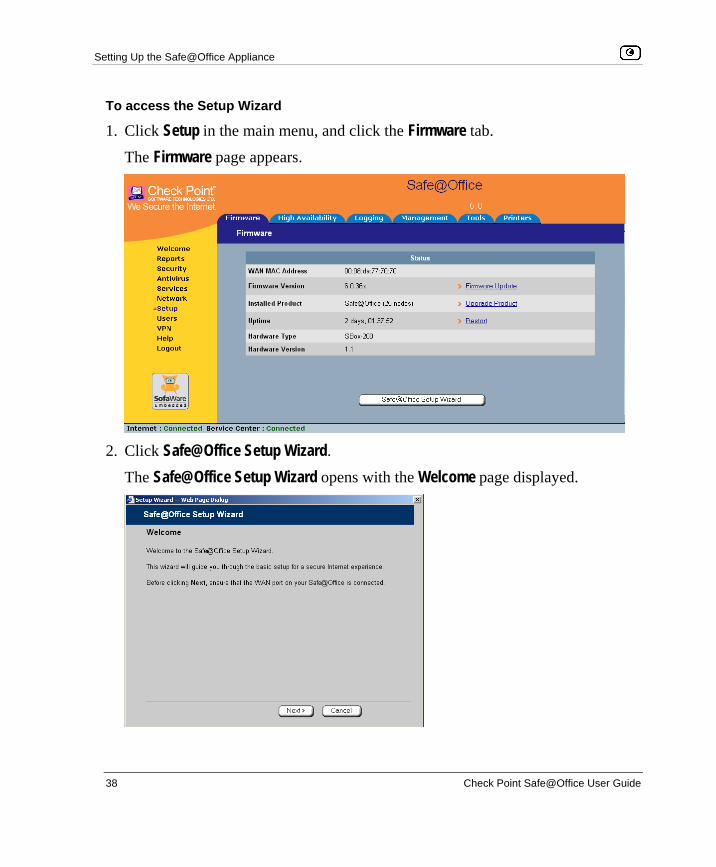
Setting Up the Safe@Office Appliance
38 Check Point Safe@Office User Guide
To access the Setup Wizard
1. Click Setup in the main menu, and click the Firmware tab.
The Firmware page appears.
2. Click Safe@Office Setup Wizard.
The Safe@Office Setup Wizard opens with the Welcome page displayed.

Initial Login to the Safe@Office Portal
Chapter 3: Getting Started 39
Chapter 3
This chapter contains all the information you need in order to get started using your Safe@Office appliance.
This chapter includes the following topics: Initial Login to the Safe@Office Portal......................................................39 Logging on to the Safe@Office Portal .......................................................42 Accessing the Safe@Office Portal Remotely Using HTTPS .....................44 Using the Safe@Office Portal ....................................................................46 Logging off.................................................................................................51
Initial Login to the Safe@Office Portal
The first time you log on to the Safe@Office Portal, you must set up your password.
To log on to the Safe@Office Portal for the first time
1. Browse to http://my.firewall.
Getting Started

Initial Login to the Safe@Office Portal
40 Check Point Safe@Office User Guide
The initial login page appears.
2. Type a password both in the Password and the Confirm Password fields.
Note: The password must be five to 25 characters (letters or numbers).
Note: You can change your password at any time. For further information, see Changing Your Password.
3. Click OK.

Initial Login to the Safe@Office Portal
Chapter 3: Getting Started 41
The Safe@Office Setup Wizard opens, with the Welcome page displayed.
4. Configure your Internet connection using one of the following ways:
• Internet Wizard
The Internet Wizard is the first part of the Setup Wizard, and it takes you through basic Internet connection setup, step by step. For information on using the Internet Wizard, see Using the Internet Wizard on page 54.
After you have completed the Internet Wizard, the Setup Wizard continues to guide you through appliance setup. For more information, see Setting Up the Safe@Office Appliance.
• Internet Setup
Internet Setup offers advanced setup options, such as configuring two Internet connections. To use Internet Setup, click Cancel and refer to Using Internet Setup on page 63.

Logging on to the Safe@Office Portal
42 Check Point Safe@Office User Guide
Logging on to the Safe@Office Portal
Note: By default, HTTP and HTTPS access to the Safe@Office Portal is not allowed from the WLAN, unless you do one of the following:
• Configure a specific firewall rule to allow access from the WLAN. See Using Rules on page 209.
Or
• Enable HTTPS access from the Internet. See Configuring HTTPS on page 392.
To log on to the Safe@Office Portal
1. Do one of the following:
• Browse to http://my.firewall.
Or
• To log on through HTTPS (locally or remotely), follow the procedure Accessing the Safe@Office Portal Remotely on page 44.

Logging on to the Safe@Office Portal
Chapter 3: Getting Started 43
The login page appears.
2. Type your username and password.
3. Click OK.

Accessing the Safe@Office Portal Remotely Using HTTPS
44 Check Point Safe@Office User Guide
The Welcome page appears.
Accessing the Safe@Office Portal Remotely Using HTTPS
You can access the Safe@Office Portal remotely (from the Internet) through HTTPS. HTTPS is a protocol for accessing a secure Web server. It is used to transfer confidential user information. If desired, you can also use HTTPS to access the Safe@Office Portal from your internal network.
Note: In order to access the Safe@Office Portal remotely using HTTPS, you must first do both of the following:
• Configure your password, using HTTP. See Initial Login to the Safe@Office Portal on page 39.
• Configure HTTPS Remote Access. See Configuring HTTPS on page 392.
Accessing the Safe@Office Portal Remotely Using HTTPS
Chapter 3: Getting Started 45
Note: Your browser must support 128-bit cipher strength. To check your browser's cipher strength, open Internet Explorer and click Help > About Internet Explorer.
To access the Safe@Office Portal from your internal network
• Browse to https://my.firewall.
(Note that the URL starts with “https”, not “http”.)
The Safe@Office Portal appears.
To access the Safe@Office Portal from the Internet
• Browse to https://<firewall_IP_address>:981.
(Note that the URL starts with “https”, not “http”.)
The following things happen in the order below:
If this is your first attempt to access the Safe@Office Portal through HTTPS, the certificate in the Safe@Office appliance is not yet known to the browser, so the Security Alert dialog box appears.
To avoid seeing this dialog box again, install the certificate of the destination Safe@Office appliance. If you are using Internet Explorer 5, do the following:
a. Click View Certificate.
The Certificate dialog box appears, with the General tab displayed.
b. Click Install Certificate.
The Certificate Import Wizard opens.
c. Click Next. d. Click Next. e. Click Finish.
f. Click Yes.
g. Click OK.

Using the Safe@Office Portal
46 Check Point Safe@Office User Guide
The Security Alert dialog box reappears.
h. Click Yes.
The Safe@Office Portal appears.
Using the Safe@Office Portal The Safe@Office Portal is a Web-based management interface, which enables you to manage and configure the Safe@Office appliance operation and options.
The Safe@Office Portal consists of three major elements.
Table 5: Safe@Office Portal Elements
Element Description
Main menu Used for navigating between the various topics (such as Reports, Security,
and Setup).
Main frame Displays information and controls related to the selected topic. The main
frame may also contain tabs that allow you to view different pages related to
the selected topic.
Status bar Shows your Internet connection and managed services status.

Using the Safe@Office Portal
Chapter 3: Getting Started 47
Figure 9: Safe@Office Portal
Main Menu The main menu includes the following submenus.
Table 6: Main Menu Submenus
This submenu…
Does this…
Welcome Displays general welcome information.
Reports Provides reporting capabilities in terms of event logging, traffic
monitoring, active computers, and established connections.
Security Provides controls and options for setting the security of any computer in
the network.
Antivirus Allows you to configure VStream Antivirus settings.
Services Allows you to control your subscription to subscription services.

Using the Safe@Office Portal
48 Check Point Safe@Office User Guide
This submenu…
Does this…
Network Allows you to manage and configure your network settings and Internet
connections.
Setup Provides a set of tools for managing your Safe@Office appliance. Allows
you to upgrade your license and firmware and to configure HTTPS
access to your Safe@Office appliance.
Users Allows you to manage Safe@Office appliance users.
VPN Allows you to manage, configure, and log on to VPN sites.
Help Provides context-sensitive help.
Logout Allows you to log off of the Safe@Office Portal.
Main Frame The main frame displays the relevant data and controls pertaining to the menu and tab you select. These elements sometimes differ depending on what model you are using. The differences are described throughout this guide.
Status Bar The status bar is located at the bottom of each page. It displays the fields below, as well as the date and time.

Using the Safe@Office Portal
Chapter 3: Getting Started 49
Table 7: Status Bar Fields
This field… Displays this…
Internet Your Internet connection status.
The connection status may be one of the following:
• Connected. The Safe@Office appliance is connected to the Internet. • Connected – Probing OK. Connection probing is enabled and has
detected that the Internet connectivity is OK. • Connected – Probing Failed. Connection probing is enabled and has
detected problems with the Internet connectivity. • Not Connected. The Internet connection is down. • Establishing Connection. The Safe@Office appliance is connecting to
the Internet. • Contacting Gateway. The Safe@Office appliance is trying to contact
the Internet default gateway. • Disabled. The Internet connection has been manually disabled.
Note: You can configure both a primary and a secondary Internet connection.
When both connections are configured, the Status bar displays both statuses.
For example “Internet [Primary]: Connected”. For information on configuring a
secondary Internet connection, see Configuring the Internet Connection on
page 53.

Using the Safe@Office Portal
50 Check Point Safe@Office User Guide
This field… Displays this…
Service
Center
Displays your subscription services status.
Your Service Center may offer various subscription services. These include
the firewall service and optional services such as Web Filtering and Email
Antivirus.
Your subscription services status may be one of the following:
• Not Subscribed. You are not subscribed to security services. • Connection Failed. The Safe@Office appliance failed to connect to
the Service Center. • Connecting. The Safe@Office appliance is connecting to the
Service Center. • Connected. You are connected to the Service Center, and security
services are active.
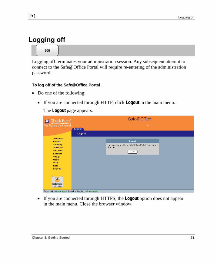
Logging off
Chapter 3: Getting Started 51
Logging off
Logging off terminates your administration session. Any subsequent attempt to connect to the Safe@Office Portal will require re-entering of the administration password.
To log off of the Safe@Office Portal
• Do one of the following:
• If you are connected through HTTP, click Logout in the main menu.
The Logout page appears.
• If you are connected through HTTPS, the Logout option does not appear
in the main menu. Close the browser window.


Overview
Chapter 4: Configuring the Internet Connection 53
Chapter 4
This chapter describes how to configure and work with an Safe@Office Internet connection.
This chapter includes the following topics: Overview ....................................................................................................53 Using the Internet Wizard ..........................................................................54 Using Internet Setup ...................................................................................63 Setting Up a Dialup Modem.......................................................................84 Viewing Internet Connection Information..................................................87 Enabling/Disabling the Internet Connection...............................................88 Using Quick Internet Connection/Disconnection .......................................90 Configuring a Backup Internet Connection................................................90
Overview You must configure your Internet connection before you can access the Internet through the Safe@Office appliance. You can configure your Internet connection using any of the following setup tools:
• Setup Wizard. Guides you through the Safe@Office appliance setup step by step. The first part of the Setup Wizard is the Internet Wizard. For further information on the Setup Wizard, see Setting Up the Safe@Office Appliance.
• Internet Wizard. Guides you through the Internet connection configuration process step by step.
• Internet Setup. Offers the following advanced setup options:
• Configure two Internet connections.
For information, see Configuring a Backup Internet Connection on page 90.
Configuring the Internet Connection
Using the Internet Wizard
54 Check Point Safe@Office User Guide
• Enable Traffic Shaper for traffic flowing through the connection.
For information on Traffic Shaper, see Using Traffic Shaper on page 151.
• Configure a dialup Internet connection.
Before configuring the connection, you must first set up the modem. For information, see Setting Up a Dialup Modem on page 84.
Using the Internet Wizard
The Internet Wizard allows you to configure your Safe@Office appliance for Internet connection quickly and easily through its user-friendly interface. It lets you to choose between the following three types of broadband connection methods:
• Direct LAN Connection
• Cable Modem
• PPTP or PPPoE dialer
Note: The first time you log on to the Safe@Office Portal, the Internet Wizard starts automatically as part of the Setup Wizard. In this case, you should skip to step 3 in the procedure below.
To set up the Internet connection using the Internet Wizard
1. Click Network in the main menu, and click the Internet tab.
The Internet page appears.
2. Click Internet Wizard.

Using the Internet Wizard
Chapter 4: Configuring the Internet Connection 55
The Internet Wizard opens with the Welcome page displayed.
3. Click Next.
The Internet Connection Method dialog box appears.
4. Select the Internet connection method you want to use for connecting to the
Internet.

Using the Internet Wizard
56 Check Point Safe@Office User Guide
Note: If you selected PPTP or PPPoE dialer, do not use your dial-up software to connect to the Internet.
5. Click Next.
Using a Direct LAN Connection No further settings are required for a direct LAN (Local Area Network) connection. The Confirmation screen appears.
1. Click Next.
The system attempts to connect to the Internet via the selected connection.
The Connecting… screen appears.
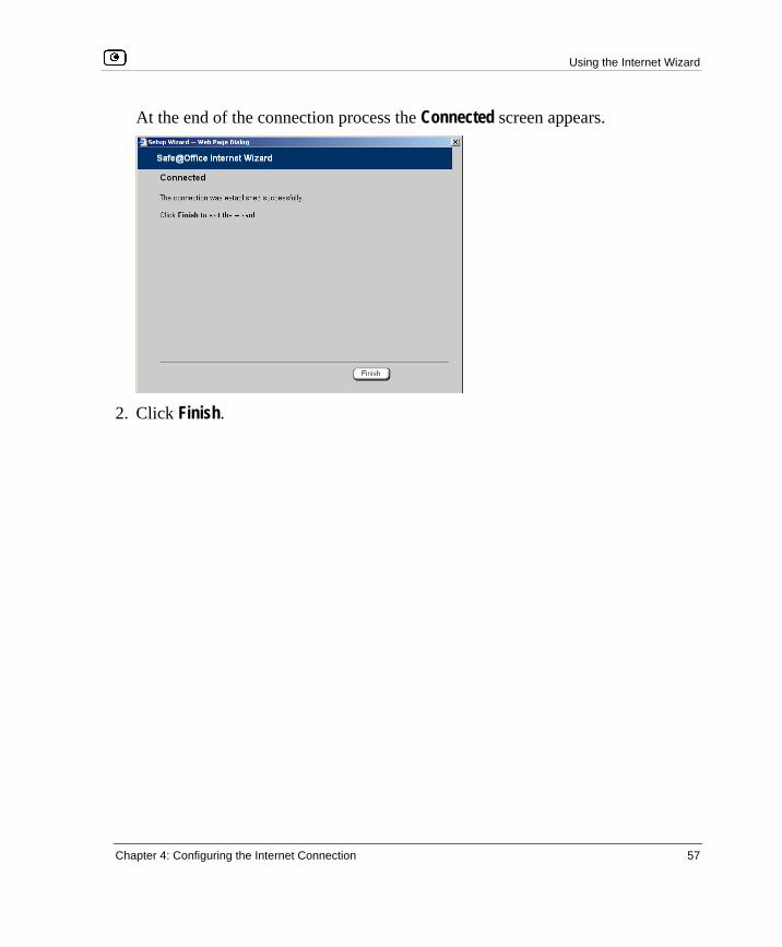
Using the Internet Wizard
Chapter 4: Configuring the Internet Connection 57
At the end of the connection process the Connected screen appears.
2. Click Finish.

Using the Internet Wizard
58 Check Point Safe@Office User Guide
Using a Cable Modem Connection If you selected the Cable Modem connection method, the Identification dialog box appears.
1. If your ISP requires a specific hostname for authentication, type it in the Host
Name field.
The ISP will supply you with the proper hostname, if required. Most ISPs do not require a specific hostname.
2. A MAC address is a 12-digit identifier assigned to every network device. If your ISP restricts connections to specific, recognized MAC addresses, they will instruct you to enter the MAC address. Otherwise, you may leave this field blank.
If your ISP requires the MAC address, do either of the following:
• Click This Computer to automatically "clone" the MAC address of your computer to the Safe@Office appliance.
Or
• If the ISP requires authentication using the MAC address of a different computer, enter the MAC address in the MAC cloning field.

Using the Internet Wizard
Chapter 4: Configuring the Internet Connection 59
3. Click Next. The Confirmation screen appears.
4. Click Next. The system attempts to connect to the Internet.
The Connecting… screen appears. At the end of the connection process the Connected screen appears.
5. Click Finish.
Using a PPTP or PPPoE Dialer Connection If you selected the PPTP or PPPoE dialer connection method, the DSL Connection Type dialog box appears.
1. Select the connection method used by your DSL provider.
Note: Most xDSL providers use PPPoE. If you are uncertain regarding which connection method to use contact your xDSL provider.
2. Click Next.

Using the Internet Wizard
Chapter 4: Configuring the Internet Connection 61
Table 8: PPPoE Connection Fields
In this field… Do this…
Username Type your user name.
Password Type your password.
Confirm password Type your password again.
Service Type your service name.
This field can be left blank.
Using PPTP If you selected the PPTP connection method, the DSL Configuration dialog box appears.
1. Complete the fields using the information in the table below.
2. Click Next. The Confirmation screen appears.

Using the Internet Wizard
62 Check Point Safe@Office User Guide
3. Click Next. The system attempts to connect to the Internet via the DSL connection.
The Connecting… screen appears.
At the end of the connection process the Connected screen appears.
4. Click Finish.
Table 9: PPTP Connection Fields
In this field… Do this…
Username Type your user name.
Password Type your password.
Confirm password Type your password again.
Service Type your service name.
Server IP Type the IP address of the PPTP modem.
Internal IP Type the local IP address required for accessing the PPTP modem.
Subnet Mask Type the subnet mask of the PPTP modem.
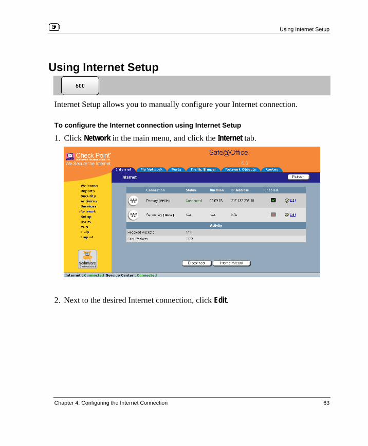
Using Internet Setup
Chapter 4: Configuring the Internet Connection 63
Using Internet Setup
Internet Setup allows you to manually configure your Internet connection.
To configure the Internet connection using Internet Setup
1. Click Network in the main menu, and click the Internet tab.
2. Next to the desired Internet connection, click Edit.
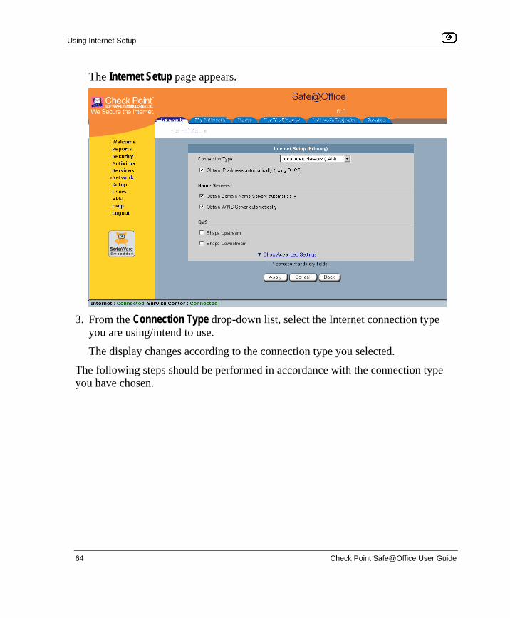
Using Internet Setup
64 Check Point Safe@Office User Guide
The Internet Setup page appears.
3. From the Connection Type drop-down list, select the Internet connection type
you are using/intend to use.
The display changes according to the connection type you selected.
The following steps should be performed in accordance with the connection type you have chosen.
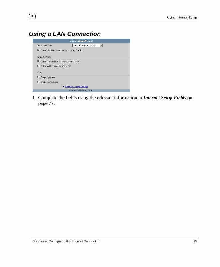
Using Internet Setup
Chapter 4: Configuring the Internet Connection 65
Using a LAN Connection
1. Complete the fields using the relevant information in Internet Setup Fields on
page 77.

Using Internet Setup
66 Check Point Safe@Office User Guide
New fields appear, depending on the check boxes you selected.
2. Click Apply.
The Safe@Office appliance attempts to connect to the Internet, and the Status Bar displays the Internet status “Connecting”. This may take several seconds.
Once the connection is made, the Status Bar displays the Internet status “Connected”.

Using Internet Setup
Chapter 4: Configuring the Internet Connection 67
Using a Cable Modem Connection
1. Complete the fields using the relevant information in Internet Setup Fields on
page 77.

Using Internet Setup
68 Check Point Safe@Office User Guide
New fields appear, depending on the check boxes you selected.
2. Click Apply.
The Safe@Office appliance attempts to connect to the Internet, and the Status Bar displays the Internet status “Connecting”. This may take several seconds.
Once the connection is made, the Status Bar displays the Internet status “Connected”.

Using Internet Setup
Chapter 4: Configuring the Internet Connection 69
Using a PPPoE Connection
1. Complete the fields using the relevant information in Internet Setup Fields on
page 77.

Using Internet Setup
70 Check Point Safe@Office User Guide
New fields appear, depending on the check boxes you selected.
2. Click Apply.
The Safe@Office appliance attempts to connect to the Internet, and the Status Bar displays the Internet status “Connecting”. This may take several seconds.
Once the connection is made, the Status Bar displays the Internet status “Connected”.

Using Internet Setup
Chapter 4: Configuring the Internet Connection 71
Using a PPTP Connection
1. Complete the fields using the relevant information in Internet Setup Fields on
page 77.
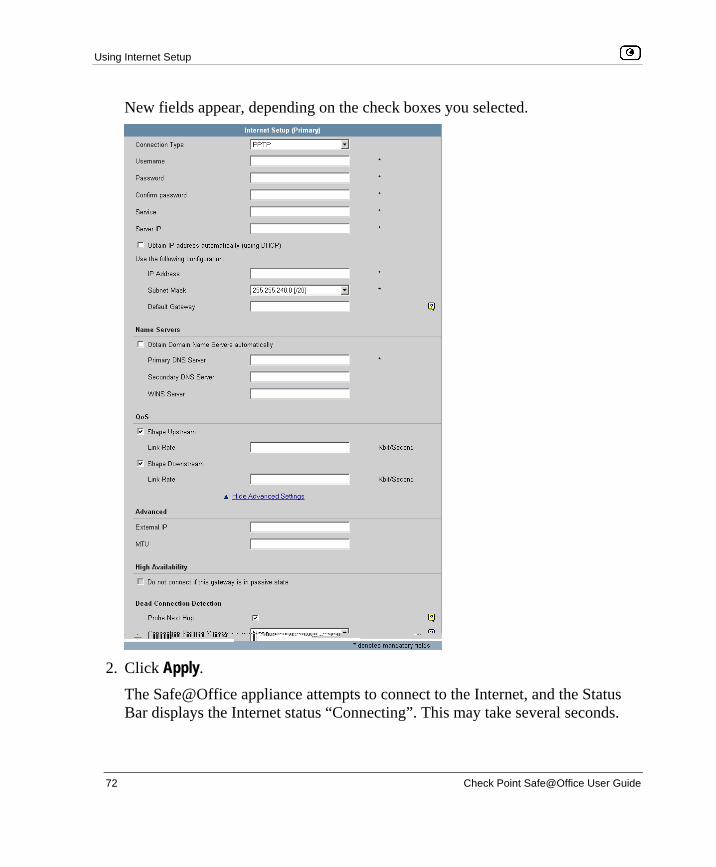
Using Internet Setup
72 Check Point Safe@Office User Guide
New fields appear, depending on the check boxes you selected.
2. Click Apply.
The Safe@Office appliance attempts to connect to the Internet, and the Status Bar displays the Internet status “Connecting”. This may take several seconds.

Using Internet Setup
Chapter 4: Configuring the Internet Connection 73
Once the connection is made, the Status Bar displays the Internet status “Connected”.
Using a Telstra (BPA) Connection Use this Internet connection type only if you are subscribed to Telstra® BigPond™ Internet. Telstra BigPond is a trademark of Telstra Corporation Limited.
1. Complete the fields using the relevant information in Internet Setup Fields on
page 77.

Using Internet Setup
74 Check Point Safe@Office User Guide
New fields appear, depending on the check boxes you selected.
2. Click Apply.
The Safe@Office appliance attempts to connect to the Internet, and the Status Bar displays the Internet status “Connecting”. This may take several seconds.
Once the connection is made, the Status Bar displays the Internet status “Connected”.

Using Internet Setup
Chapter 4: Configuring the Internet Connection 75
Using a Dialup Connection To use this connection type, you must first set up the dialup modem. For information, see Setting Up a Dialup Modem on page 84.
1. Complete the fields using the relevant information in Internet Setup Fields on
page 77.

Using Internet Setup
76 Check Point Safe@Office User Guide
New fields appear, depending on the check boxes you selected.
2. Click Apply.
The Safe@Office appliance attempts to connect to the Internet, and the Status Bar displays the Internet status “Connecting”. This may take several seconds.
Once the connection is made, the Status Bar displays the Internet status “Connected”.

Using Internet Setup
Chapter 4: Configuring the Internet Connection 77
Using No Connection If you do not have an Internet connection, set the connection type to None.
• Click Apply.
Table 10: Internet Setup Fields
In this field… Do this…
Username Type your user name.
Password Type your password.
Confirm password Type your password.
Service Type your service name.
If your ISP has not provided you with a service name, leave this field
empty.
Server IP If you selected PPTP, type the IP address of the PPTP server as given
by your ISP.
If you selected Telstra (BPA), type the IP address of the Telstra
authentication server as given by Telstra.
Phone Number If you selected Dialup, type the phone number that the modem should
dial, as given by your ISP.

Using Internet Setup
78 Check Point Safe@Office User Guide
In this field… Do this…
Connect on
demand Select this option if you do not want the dialup modem to be constantly
connected to the Internet. The modem will dial a connection only under
certain conditions.
This option is useful when configuring a dialup backup connection. For
information, see Setting Up a Dialup Backup Connection on page 92.
When no higher
priority connection
is available
Select this option to specify that the dialup modem should only dial a
connection if no other connection exists, and the Safe@Office appliance
is not acting as a Backup appliance.
If another connection opens, the dialup modem will disconnect.
For information on configuring the appliance as a Backup or Master, see
Configuring High Availability on page 119.
On outgoing
activity
Select this option to specify that the dialup modem should only dial a
connection if no other connection exists, and there is outgoing activity
(that is, packets need to be transmitted to the Internet).
If another connection opens, or if the connection times out, the dialup
modem will disconnect.
Idle timeout Type the amount of time (in minutes) that the connection can remain idle.
Once this period of time has elapsed, the dialup modem will disconnect.
Obtain IP address
automatically
(using DHCP)
Clear this option if you do not want the Safe@Office appliance to obtain
an IP address automatically using DHCP.
IP Address Type the static IP address of your Safe@Office appliance.
Subnet Mask Select the subnet mask that applies to the static IP address of your
Safe@Office appliance.

Using Internet Setup
Chapter 4: Configuring the Internet Connection 79
In this field… Do this…
Default Gateway Type the IP address of your ISP’s default gateway.
Name Servers
Obtain Domain
Name Servers
automatically
Clear this option if you want the Safe@Office appliance to obtain an IP
address automatically using DHCP, but not to automatically configure
DNS servers.
Obtain WINS
Server
automatically
Clear this option if you want the Safe@Office appliance to obtain an IP
address automatically using DHCP, but not to automatically configure the
WINS server.
Primary DNS
Server
Type the Primary DNS server IP address.
Secondary DNS
Server
Type the Secondary DNS server IP address.
WINS Server Type the WINS server IP address.
QoS
Shape Upstream:
Link Rate
Select this option to enable Traffic Shaper for outgoing traffic. Then type
a rate (in kilobits/second) slightly lower than your Internet connection's
maximum measured upstream speed in the field provided.
It is recommended to try different rates in order to determine which one
provides the best results.
For information on using Traffic Shaper, see Using Traffic Shaper on
page 151.

Using Internet Setup
80 Check Point Safe@Office User Guide
In this field… Do this…
Shape
Downstream: Link
Rate
Select this option to enable Traffic Shaper for incoming traffic. Then type
a rate (in kilobits/second) slightly lower than your Internet connection's
maximum measured downstream speed in the field provided.
It is recommended to try different rates in order to determine which one
provides the best results.
Note: Traffic Shaper cannot control the number or type of packets it
receives from the Internet; it can only affect the rate of incoming traffic by
dropping received packets. This makes the shaping of inbound traffic
less accurate than the shaping of outbound traffic. It is therefore
recommended to enable traffic shaping for incoming traffic only if
necessary.
For information on using Traffic Shaper, see Using Traffic Shaper on
page 151.
Advanced
External IP If you selected PPTP, type the IP address of the PPTP client as given by
your ISP.
If you selected PPPoE, this field is optional, and you do not have to fill it
in unless your ISP has instructed you to do so.
MTU This field allows you to control the maximum transmission unit size.
As a general recommendation you should leave this field empty. If
however you wish to modify the default MTU, it is recommended that you
consult with your ISP first and use MTU values between 1300 and 1500.

Using Internet Setup
Chapter 4: Configuring the Internet Connection 81
In this field… Do this…
MAC Cloning A MAC address is a 12-digit identifier assigned to every network device. If
your ISP restricts connections to specific, recognized MAC addresses, you
must select this option to clone a MAC address.
Note: When configuring MAC cloning for the secondary Internet
connection, the DMZ/WAN2 port must be configured as WAN2; otherwise
this field is disabled. For information on configuring ports, see Managing Ports on page 145.
Hardware MAC
Address
This field displays the Safe@Office appliance's MAC address.
This field is read-only.
Cloned MAC
Address
Do one of the following:
• Click This Computer to automatically "clone" the MAC address of your computer to the Safe@Office appliance.
• If the ISP requires authentication using the MAC address of a different computer, type the MAC address in this field.
Note: In the secondary Internet connection, this field is enabled only if the
DMZ/WAN2 port is set to WAN2.
High Availability The High Availability area only appears in Safe@Office 500 with Power
Pack.
Do not connect if
this gateway is in
passive state
If you are using High Availability (HA), select this option to specify that the
gateway should connect to the Internet only if it is the Active Gateway in
the HA cluster.
This field is only enabled if HA is configured.
For information on HA, see Configuring High Availability on page 119.
Dead Connection Detection

Using Internet Setup
82 Check Point Safe@Office User Guide
In this field… Do this…
Probe Next Hop Select this option to automatically detect loss of connectivity to the default
gateway. If you selected LAN, this is done by sending ARP requests to the
default gateway. If you selected PPTP, PPPoE, or Dialup, this is done by
sending PPP echo reply (LCP) messages to the PPP peer.
By default, if the default gateway does not respond, the Internet
connection is considered to be down.
If it is determined that the Internet connection is down, and two Internet
connections are defined, a failover will be performed to the second
Internet connection, ensuring continuous Internet connectivity.
This option is selected by default.

Using Internet Setup
Chapter 4: Configuring the Internet Connection 83
In this field… Do this…
Connection Probing
Method
While the Probe Next Hop option checks the availability of the next hop
router, which is usually at your ISP, connectivity to the next hop router
does not always indicate that the Internet is accessible. For example, if
there is a problem with a different router at the ISP, the next hop will be
reachable, but the Internet might be inaccessible. Connection probing is a
way to detect Internet failures that are more than one hop away.
Specify what method to use for probing the connection, by selecting one
of the following:
• None. Do not perform Internet connection probing. Next hop probing will still be used, if the Probe Next Hop check box is selected. This is the default value.
• Ping Addresses. Ping anywhere from one to three servers specified by IP address or DNS name in the 1, 2, and 3 fields. If for 45 seconds none of the defined servers respond to pinging, the Internet connection is considered to be down. Use this method if you have reliable servers that can be pinged, that are a good indicator of Internet connectivity, and that are not likely to fail simultaneously (that is, they are not at the same location).
• Probe DNS Servers. Probe the primary and secondary DNS servers. If for 45 seconds neither gateway responds, the Internet connection is considered to be down. Use this method if the availability of your DNS servers is a good indicator for the availability of Internet connectivity.
• Probe VPN Gateway (RDP). Send RDP echo requests to up to three Check Point VPN gateways specified by IP address or DNS name in the 1, 2, and 3 fields. If for 45 seconds none of the defined gateways respond, the Internet connection is considered to be down. Use this option if you have Check Point VPN gateways, and you want loss of connectivity to these gateways to trigger ISP failover to an Internet connection from which these gateways are reachable.

Setting Up a Dialup Modem
84 Check Point Safe@Office User Guide
In this field… Do this…
1, 2, 3 If you chose the Ping Addresses connection probing method, type the IP
addresses or DNS names of the desired servers.
If you chose the Probe VPN Gateway (RDP) connection probing method, type
the IP addresses or DNS names of the desired VPN gateways.
You can clear a field by clicking Clear.
Setting Up a Dialup Modem
You can use a dialup modem as a primary or secondary Internet connection method. This is useful in locations where broadband Internet access is unavailable.
When used as a backup Internet connection, the modem can be automatically disconnected when not in use. For information on setting up a dialup backup connection, see Setting Up a Dialup Backup Connection on page 92.
To set up a dialup modem
1. Connect a regular or ISDN dialup modem to your Safe@Office appliance's serial port.
For information on locating the serial port, see Rear Panel.
2. Click Network in the main menu, and click the Ports tab.

Setting Up a Dialup Modem
Chapter 4: Configuring the Internet Connection 85
The Ports page appears.
3. In the RS232 drop-down list, select Dialup.
4. Click Apply.
5. Next to the RS232 drop-down list, click Setup.

Setting Up a Dialup Modem
86 Check Point Safe@Office User Guide
The Dialup page appears.
6. Complete the fields using the information in the table below.
7. Click Apply.
8. To check that that the values you entered are correct, click Test. The Dialup page displays a message indicat

Viewing Internet Connection Information
Chapter 4: Configuring the Internet Connection 87
In this field… Do this…
Dial Mode Select the dial mode the modem uses.
Port Speed Select the modem's port speed (in bits per second).
Viewing Internet Connection Information
You can view information on your Internet connection(s) in terms of status, duration, and activity.
To view Internet connection information
1. Click Network in the main menu, and click the Internet tab.
The Internet page appears.
For an explanation of the fields on this page, see the table below.
2. To refresh the information on this page, click Refresh.

Enabling/Disabling the Internet Connection
88 Check Point Safe@Office User Guide
Table 12: Internet Page Fields
Field Description
Status Indicates the connection’s status.
Duration Indicates the connection duration, if active. The duration is given in the
format hh:mm:ss, where:
hh=hours
mm=minutes
ss=seconds
IP Address Your IP address.
Enabled Indicates whether or not the connection is enabled.
For further information, see Enabling/Disabling the Internet Connection on page 88
Received Packets The number of data packets received in the active connection.
Sent Packets The number of data packets sent in the active connection.
Enabling/Disabling the Internet Connection
You can temporarily disable an Internet connection. This is useful if, for example, you are going on vacation and do not want to leave your computer connected to the Internet. If you have two Internet connections, you can force the Safe@Office appliance to use a particular connection, by disabling the other connection.
The Internet connection’s Enabled/Disabled status is persistent through Safe@Office appliance reboots.

Enabling/Disabling the Internet Connection
Chapter 4: Configuring the Internet Connection 89
To enable/disable an Internet connection
1. Click Network in the main menu, and click the Internet tab.
The Internet page appears.
2. Next to the Internet connection, do one of the following:
• To enable the connection, click .
The button changes to and the connection is enabled.
• To disable the connection, click .
The button changes to and the connection is disabled.

Using Quick Internet Connection/Disconnection
90 Check Point Safe@Office User Guide
Using Quick Internet Connection/Disconnection
By clicking the Connect or Disconnect button (depending on the connection status) on the Internet page, you can establish a quick Internet connection using the currently-selected connection type. In the same manner, you can terminate the active connection.
The Internet connection retains its Connected/Not Connected status until the Safe@Office appliance is rebooted. The Safe@Office appliance then connects to the Internet if the connection is enabled. For information on enabling an Internet connection, see Enabling/Disabling the Internet Connection on page 88.
Configuring a Backup Internet Connection You can configure both a primary and a secondary Internet connection. The secondary connection acts as a backup, so that if the primary connection fails, the Safe@Office appliance remains connected to the Internet.
Note: You can configure different DNS servers for the primary and secondary connections. The Safe@Office appliance acts as a DNS relay and routes requests from computers within the network to the appropriate DNS server for the active Internet connection.

Configuring a Backup Internet Connection
Chapter 4: Configuring the Internet Connection 91
Setting Up a LAN or Broadband Backup Connection
Using the Safe@Office Appliance's WAN Port
To set up a LAN or broadband backup Internet connection
1. Connect a hub or switch to the WAN port on your appliance's rear panel.
2. Connect your two modems or routers to the hub/switch.
3. Configure two Internet connections.
For instructions, see Using Internet Setup on page 63.
Important: The two connections can be of different types. However, they cannot both be LAN DHCP connections.
Using the Safe@Office Appliance's DMZ/WAN2 Port
To set up a LAN or broadband backup Internet connection
1. Connect a modem to the DMZ/WAN2 port on your appliance's rear panel.
2. Click Network in the main menu, and click the Ports tab.
The Ports page appears.
3. In the DMZ/WAN2 drop-down list, select WAN2.
4. Click Apply.
5. Configure two Internet connections.
For instructions, see Using Internet Setup on page 63.

Configuring a Backup Internet Connection
92 Check Point Safe@Office User Guide
Setting Up a Dialup Backup Connection
If desired, you can use a dialup modem as the secondary Internet connection method. The Safe@Office appliance automatically dials the modem if the primary Internet connection fails.
To set up a dialup backup Internet connection
1. Setup a dialup modem.
For instructions, see Setting Up a Dialup Modem on page 84.
2. Configure a LAN or broadband primary Internet connection.
For instructions, see Using Internet Setup on page 63.
3. Configure a Dialup secondary Internet connection.
For instructions, see Using Internet Setup on page 63.

Configuring Network Settings
Chapter 5: Managing Your Network 93
Chapter 5
This chapter describes how to manage and configure your network connection and settings.
This chapter includes the following topics: Configuring Network Settings....................................................................93 Configuring High Availability..................................................................119 Using Static Routes ..................................................................................139 Managing Ports.........................................................................................145
Configuring Network Settings
Warning: These are advanced settings. Do not change them unless it is necessary and you are qualified to do so.
Note: If you change the network settings to incorrect values and are unable to correct the error, you can reset the Safe@Office appliance to its default settings. See Resetting the Safe@Office appliance to Defaults on page 420.
Managing Your Network

Configuring Network Settings
94 Check Point Safe@Office User Guide
Configuring a DHCP Server
By default, the Safe@Office appliance operates as a DHCP (Dynamic Host Configuration Protocol) server. This allows the Safe@Office appliance to automatically configure all the devices on your network with their network configuration details.
Note: The DHCP server only serves computers that are configured to obtain an IP address automatically. If a computer is not configured to obtain an IP address automatically, it is recommended to assign it an IP address outside of the DHCP address range. If you do assign it an IP address within the DHCP address range, the DHCP server will not assign this IP address to another computer.
If you already have a DHCP server in your internal network, and you want to use it instead of the Safe@Office DHCP server, you must disable the Safe@Office DHCP server, since you cannot have two DHCP servers or relays on the same network segment.
If you want to use a DHCP server on the Internet or via a VPN, instead of the Safe@Office DHCP server, you can configure DHCP relay. When in DHCP relay mode, the Safe@Office appliance relays information from the desired DHCP server to the devices on your network.
Note: You can perform DHCP reservation using network objects. For information, see Using Network Objects on page 129.

Configuring Network Settings
Chapter 5: Managing Your Network 95
Enabling/Disabling the Safe@Office DHCP Server
You can enable and disable the Safe@Office DHCP Server for internal networks.
Note: Enabling and disabling the DHCP Server is not available for the OfficeMode network.
To enable/disable the Safe@Office DHCP server
1. Click Network in the main menu, and click the My Network tab.
The My Network page appears.
2. In the desired network's row, click Edit.

Configuring Network Settings
96 Check Point Safe@Office User Guide
The Edit Network Settings page appears.
3. From the DHCP Server list, select Enabled or Disabled.
4. Click Apply.
A warning message appears.
5. Click OK.
A success message appears
6. If your computer is configured to obtain its IP address automatically (using DHCP), and either the Safe@Office DHCP server or another DHCP server is enabled, restart your computer.
If you enabled the DHCP server, your computer obtains an IP address in the DHCP address range.

Configuring Network Settings
Chapter 5: Managing Your Network 97
Configuring the DHCP Address Range
By default, the Safe@Office DHCP server automatically sets the DHCP address range. The DHCP address range is the range of IP addresses that the DHCP server can assign to network devices. IP addresses outside of the DHCP address range are reserved for statically addressed computers.
If desired, you can set the Safe@Office DHCP range manually.
Note: Setting the DHCP range manually is not available for the OfficeMode network.
To configure the DHCP address range
1. Click Network in the main menu, and click the My Network tab.
The My Network page appears.
2. In the desired network's row, click Edit. The Edit Network Settings page appears.
3. To set the DHCP range manually:
a. Clear the Automatic DHCP range check box.

Configuring Network Settings
98 Check Point Safe@Office User Guide
The DHCP IP range fields appear.
b. In the DHCP IP range fields, type the desired DHCP range.
4. To allow the DHCP server to set the IP address range, select the Automatic DHCP range check box.
5. Click Apply.
A warning message appears.
6. Click OK.
A success message appears
7. If your computer is configured to obtain its IP address automatically (using DHCP), and either the Safe@Office DHCP server or another DHCP server is enabled, restart your computer.
Your computer obtains an IP address in the new DHCP address range.

Configuring Network Settings
Chapter 5: Managing Your Network 99
Configuring DHCP Relay
You can configure DHCP relay for internal networks.
Note: DHCP relay will not work if the appliance is located behind a NAT device.
Note: Configuring DHCP options is not available for the OfficeMode network.
To configure DHCP relay
1. Click Network in the main menu, and click the My Network tab.
The My Network page appears.
2. In the desired network's row, click Edit. The Edit Network Settings page appears.
3. In the DHCP Server list, select Relay.

Configuring Network Settings
100 Check Point Safe@Office User Guide
The Automatic DHCP range check box is disabled, and the Relay to IP field appears.
4. In the Relay to IP field, type the IP address of the desired DHCP server.
5. Click Apply.
A warning message appears.
6. Click OK.
A success message appears
7. If your computer is configured to obtain its IP address automatically (using DHCP), and either the Safe@Office DHCP server or another DHCP server is enabled, restart your computer.
Your computer obtains an IP address in the DHCP address range.

Configuring Network Settings
Chapter 5: Managing Your Network 101
Configuring DHCP Server Options
If desired, you can configure the following custom DHCP options for an internal network:
• Domain suffix
• DNS servers
• WINS servers
• NTP servers
• VoIP call managers
• TFTP server and boot filename
Note: Configuring DHCP options is not available for the DMZ or VLANs.
To configure DHCP options
1. Click Network in the main menu, and click the My Network tab.
The My Network page appears.
2. In the desired network's row, click Edit. The Edit Network Settings page appears.
3. In the DHCP area, click Options.

Configuring Network Settings
102 Check Point Safe@Office User Guide
The DHCP Server Options page appears.
4. Complete the fields using the relevant information in the table below.

Configuring Network Settings
Chapter 5: Managing Your Network 103
New fields appear, depending on the check boxes you selected.
5. Click Apply.
6. If your computer is configured to obtain its IP address automatically (using DHCP), restart your computer.
Your computer obtains an IP address in the DHCP address range.
Table 13: DHCP Server Options Fields
In this field… Do this…
Domain Name Type a default domain suffix that should be passed to DHCP clients.
The DHCP client will automatically append the domain suffix for the
resolving of non-fully qualified names. For example, if the domain suffix
is set to "mydomain.com", and the client tries to resolve the name
“mail”, the suffix will be automatically appended to the name, resulting
in “mail.mydomain.com”.

Configuring Network Settings
104 Check Point Safe@Office User Guide
In this field… Do this…
Name Servers
Automatically assign
DNS server
(recommended)
Clear this option if you do not want the gateway to act as a DNS relay
server and pass its own IP address to DHCP clients.
Normally, it is recommended to leave this option selected.
The DNS Server 1 and DNS Server 2 fields appear.
DNS Server 1, 2 Type the IP addresses of the Primary and Secondary DNS servers to
pass to DHCP clients instead of the gateway.
Automatically assign
WINS server
Clear this option if you do not want DHCP clients to be assigned the
same WINS servers as specified by the Internet connection configuration (in the Internet Setup page).
The WINS Server 1 and WINS Server 2 fields appear.
WINS Server 1, 2 Type the IP addresses of the Primary and Secondary WINS servers to
use instead of the gateway.
Other Services These fields are not available for the OfficeMode network.
Time Server 1, 2 To use Network Time Protocol (NTP) servers to synchronize the time
on the DHCP clients, type the IP address of the Primary and
Secondary NTP servers.
Call Manager 1, 2 To assign Voice over Internet Protocol (VoIP) call managers to the
DHCP clients, type the IP address of the Primary and Secondary VoIP
servers.

Configuring Network Settings
Chapter 5: Managing Your Network 105
In this field… Do this…
TFTP Server Trivial File Transfer Protocol (TFTP) enables booting diskless
computers over the network.
To assign a TFTP server to the DHCP clients, type the IP address of
the TFTP server.
TFTP Boot File Type the boot file to use for booting DHCP clients via TFTP.
Changing IP Addresses
If desired, you can change your Safe@Office appliance’s internal IP address, or the entire range of IP addresses in your internal network. You may want to perform these tasks if, for example, you are adding the Safe@Office appliance to a large existing network and don't want to change that network’s IP address range, or if you are using a DHCP server other than the Safe@Office appliance, that assigns addresses within a different range.
To change IP addresses
1. Click Network in the main menu, and click the My Network tab.
The My Network page appears.
2. In the LAN network's row, click Edit. The Edit Network Settings page appears.
3. To change the Safe@Office appliance’s internal IP address, enter the new IP address in the IP Address field.
4. To change the internal network range, enter a new value in the Subnet Mask field.

Configuring Network Settings
106 Check Point Safe@Office User Guide
Note: The internal network range is defined both by the Safe@Office appliance’s internal IP address and by the subnet mask.
For example, if the Safe@Office appliance’s internal IP address is 192.168.100.7, and you set the subnet mask to 255.255.255.0, the network’s IP address range will be 192.168.100.1 – 192.168.100.254.
The default internal network range is 192.168.10.*.
5. Click Apply.
A warning message appears.
6. Click OK.
• The Safe@Office appliance's internal IP address and/or the internal network range are changed.
• A success message appears. 7. Do one of the following:
• If your computer is configured to obtain its IP address automatically (using DHCP), and the Safe@Office DHCP server is enabled, restart your computer.
Your computer obtains an IP address in the new range.
• Otherwise, manually reconfigure your computer to use the new address range using the TCP/IP settings. For information on configuring TCP/IP, see TCP/IP Settings on page 24, on page 20.

Configuring Network Settings
Chapter 5: Managing Your Network 107
Enabling/Disabling Hide NAT
Hide Network Address Translation (Hide NAT) enables you to share a single public Internet IP address among several computers, by “hiding” the private IP addresses of the internal computers behind the Safe@Office appliance’s single Internet IP address.
Note: If Hide NAT is disabled, you must obtain a range of Internet IP addresses from your ISP. Hide NAT is enabled by default.
Note: Static NAT and Hide NAT can be used together.
To enable/disable Hide NAT
1. Click Network in the main menu, and click the My Network tab.
The My Network page appears.
2. In the desired network's row, click Edit. The Edit Network Settings page appears.
3. From the Hide NAT list, select Enabled or Disabled.
4. Click Apply.
A warning message appears.
5. Click OK.
• If you chose to disable Hide NAT, it is disabled.
• If you chose to enable Hide NAT, it is enabled.

Configuring Network Settings
108 Check Point Safe@Office User Guide
Configuring a DMZ Network
In addition to the LAN network, you can define a second internal network called a DMZ (demilitarized zone) network.
For information on default security policy rules controlling traffic to and from the DMZ, see Default Security Policy on page 203.
To configure a DMZ network
1. Connect the DMZ computer to the DMZ port.
If you have more than one computer in the DMZ network, connect a hub or switch to the DMZ port, and connect the DMZ computers to the hub.
2. Click Network in the main menu, and click the Ports tab.
The Ports page appears.

Configuring Network Settings
Chapter 5: Managing Your Network 109
3. In the DMZ drop-down list, select DMZ.
4. Click Apply.
5. Click Network in the main menu, and click the My Network tab.
The My Network page appears.
6. In the DMZ network's row, click Edit. The Edit Network Settings page appears.
7. In the Mode drop-down list, select Enabled.
The fields are enabled.
8. If desired, enable or disable Hide NAT.
See Enabling/Disabling Hide NAT on page 107.
9. If desired, configure a DHCP server.
See Configuring a DHCP Server on page 94.
10. In the IP Address field, type the IP address of the DMZ network's default gateway.
Note: The DMZ network must not overlap other networks.
11. In the Subnet Mask text box, type the DMZ’s internal network range.
12. Click Apply.
A warning message appears.
13. Click OK.
A success message appears.

Configuring Network Settings
110 Check Point Safe@Office User Guide
Configuring the OfficeMode Network
By default, VPN Clients connect to the VPN Server using an Internet IP address locally assigned by an ISP. This may lead to the following problems:
• VPN Clients on the same network will be unable to communicate with each other via the Safe@Office Internal VPN Server. This is because their IP addresses are on the same subnet, and they therefore attempt to communicate directly over the local network, instead of through the secure VPN link.
• Some networking protocols or resources may require the client’s IP address to be an internal one.
OfficeMode solves these problems by enabling the Safe@Office DHCP Server to automatically assign a unique local IP address to the VPN client, when the client connects and authenticates. The IP addresses are allocated from a pool called the OfficeMode network.
Note: OfficeMode requires Check Point SecureClient to be installed on the VPN clients. It is not supported by Check Point SecuRemote.
When OfficeMode is not supported by the VPN client, traditional mode will be selected used instead.
To configure the OfficeMode network
1. Click Network in the main menu, and click the My Network tab.
The My Network page appears.
2. In the OfficeMode network's row, click Edit. The Edit Network Settings page appears.
3. In the Mode drop-down list, select Enabled.
The fields are enabled.

Configuring Network Settings
Chapter 5: Managing Your Network 111
4. In the IP Address field, type the IP address to use as the OfficeMode network's default gateway.
Note: The OfficeMode network must not overlap other networks.
5. In the Subnet Mask text box, type the OfficeMode internal network range.
6. If desired, enable or disable Hide NAT.
See Enabling/Disabling Hide NAT on page 107.
7. If desired, configure DHCP options.
See Configuring DHCP Server Options on page 101.
8. Click Apply.
A warning message appears.
9. Click OK.
A success message appears.
Configuring VLANs
Your Safe@Office appliance allows you partition your network into several virtual LAN networks (VLANs). A VLAN is a logical network behind the Safe@Office appliance. Computers in the same VLAN behave as if they were on the same physical network: traffic flows freely between them, without passing through a firewall. In contrast, traffic between a VLAN and other networks passes through the firewall and is subject to the security policy. By default, traffic from a VLAN to any other internal network (including other VLANs) is blocked. In this way, defining VLANs can increase security and reduce network congestion.
For example, you can assign each division within your organization to a different VLAN, regardless of their physical location. The members of a division will be able to communicate with each other and share resources, and only members who need to communicate with other divisions will be allowed to do so. Furthermore,

Configuring Network Settings
112 Check Point Safe@Office User Guide
you can easily transfer a member of one division to another division without rewiring your network, by simply reassigning them to the desired VLAN.
The Safe@Office appliance supports the following VLAN types:
• Tag-based In tag-based VLAN you use one of the gateway’s ports as a 802.1Q VLAN trunk, connecting the appliance to a VLAN-aware switch. Each VLAN behind the trunk is assigned an identifying number called a “VLAN ID”, also referred to as a "VLAN tag". All outgoing traffic from a tag-based VLAN contains the VLAN's tag in the packet headers. Incoming traffic to the VLAN must contain the VLAN's tag as well, or the packets are dropped. Tagging ensures that traffic is directed to the correct VLAN.
Figure 10: Tag-based VLAN

Configuring Network Settings
Chapter 5: Managing Your Network 113
• Port-based Port-based VLAN allows assigning the appliance's LAN ports to VLANs, effectively transforming the appliance's four-port switch into up to four firewall-isolated security zones. You can assign multiple ports to the same VLAN, or each port to a separate VLAN.
Figure 11: Port-based VLAN
Port-based VLAN does not require an external VLAN-capable switch, and is therefore simpler to use than tag-based VLAN. However, port-based VLAN is limited, because the appliance's internal switch has only four ports.
You can define up to ten VLAN networks (port-based and tag-based combined).
For information on the default security policy for VLANs, see Default Security Policy on page 203.

Configuring Network Settings
114 Check Point Safe@Office User Guide
Adding and Editing Port-Based VLANs
To add or edit a port-based VLAN
1. Click Network in the main menu, and click the My Network tab.
The My Network page appears.
2. Do one of the following:
• To add a VLAN site, click Add VLAN.
• To edit a VLAN site, click Edit in the desired VLAN’s row. The Edit Network Settings page for VLAN networks appears.
3. In the Network Name field, type a name for the VLAN.
4. In the Type drop-down list, select Port Based VLAN.
The VLAN Tag field disappears.

Configuring Network Settings
Chapter 5: Managing Your Network 115
5. In the IP Address field, type the IP address of the VLAN network's default gateway.
Note: The VLAN network must not overlap other networks.
6. In the Subnet Mask field, type the VLAN's internal network range.
7. If desired, enable or disable Hide NAT.
See Enabling/Disabling Hide NAT on page 107.
8. If desired, configure a DHCP server.
See Configuring a DHCP Server on page 94.
9. Click Apply.
A warning message appears.
10. Click OK.
A success message appears.
11. Click Network in the main menu, and click the Ports tab.
The Ports page appears.
12. In the drop-down list next to the LAN port you want to assign, select the VLAN network's name.
You can assign more than one port to the VLAN.
13. Click Apply.

Configuring Network Settings
116 Check Point Safe@Office User Guide
Adding and Editing Tag-Based VLANs
To add or edit a tag-based VLAN
1. Click Network in the main menu, and click the My Network tab.
The My Network page appears.
2. Do one of the following:
• To add a VLAN site, click Add VLAN.
• To edit a VLAN site, click Edit in the desired VLAN’s row. The Edit Network Settings page for VLAN networks appears.
3. In the Network Name field, type a name for the VLAN.
4. In the Type drop-down list, select Tag Based VLAN.
The VLAN Tag field appears.
5. In the VLAN Tag field, type a tag for the VLAN.
This must be an integer between 1 and 4095.
6. In the IP Address field, type the IP address of the VLAN network's default gateway.
Note: The VLAN network must not overlap other networks.
7. In the Subnet Mask field, type the VLAN's internal network range.
8. If desired, enable or disable Hide NAT.
See Enabling/Disabling Hide NAT on page 107.
9. If desired, configure a DHCP server.
See Configuring a DHCP Server on page 94.

Configuring Network Settings
Chapter 5: Managing Your Network 117
10. Click Apply.
A warning message appears.
11. Click OK.
A success message appears.
12. Click Network in the main menu, and click the Ports tab.
The Ports page appears.
13. In the DMZ/WAN2 drop-down list, select VLAN Trunk.
14. Click Apply.
The DMZ/WAN2 port now operates as a VLAN Trunk port. In this mode, it will not accept untagged packets.
15. Configure a VLAN trunk (802.1Q) port on the VLAN-aware switch, according to the vendor instructions. Define the same VLAN IDs on the switch.
16. Connect the Safe@Office appliance's DMZ/WAN2 port to the VLAN-aware switch's VLAN trunk port.

Configuring Network Settings
118 Check Point Safe@Office User Guide
Deleting VLANs
To delete a VLAN
1. If the VLAN is port-based, do the following:
a. Click Network in the main menu, and click the Ports tab.
The Ports page appears.
b. Remove all port assignments to the VLAN, by selecting other networks in the drop-down lists.
c. Click Apply. 2. Click Network in the main menu, and click the My Network tab.
The My Network page appears.
3. In the desired VLAN’s row, click the Erase icon.
A confirmation message appears.
4. Click OK.
The VLAN is deleted.
Configuring High Availability
Chapter 5: Managing Your Network 119
Configuring High Availability
You can create a High Availability (HA) cluster consisting of two or more Safe@Office appliances. For example, you can install two Safe@Office appliances on your network, one acting as the “Master”, the default gateway through which all network traffic is routed, and one acting as the “Backup”. If the Master fails, the Backup automatically and transparently takes over all the roles of the Master. This ensures that your network is consistently protected by a Safe@Office appliance and connected to the Internet.
The gateways in a HA cluster each have a separate IP address within the local network. In addition, the gateways share a single virtual IP address, which is the default gateway address for the local network. Control of the virtual IP address is passed as follows:
1. Each gateway is assigned a priority, which determines the gateway's role: the gateway with the highest priority is the Active Gateway and uses the virtual IP address, and the rest of the gateways are Passive Gateways.
2. The Active Gateway sends periodic signals, or “heartbeats”, to the network via a synchronization interface.
The synchronization interface can be any internal network existing on both gateways except the WLAN.
3. If the heartbeat from the Active Gateway stops (indicating that the Active gateway has failed), the gateway with the highest priority becomes the new Active Gateway and takes over the virtual IP address.
4. When a gateway that was offline comes back online, or a gateway's priority changes, the gateway sends a heartbeat notifying the other gateways in the cluster.
If the gateway's priority is now the highest, it becomes the Active Gateway.
The Safe@Office appliance supports Internet connection tracking, which means that each appliance tracks its Internet connection's status and reduces its own

Configuring High Availability
120 Check Point Safe@Office User Guide
priority by a user-specified amount, if its Internet connection goes down. If the Active Gateway's priority drops below another gateway's priority, then the other gateway becomes the Active Gateway.
Note: You can force a fail-over to a passive Safe@Office appliance. You may want to do this in order to verify that HA is working properly, or if the active Safe@Office appliance needs repairs. To force a fail-over, switch off the primary box or disconnect it from the LAN network.
The Safe@Office appliance supports configuring multiple HA clusters on the same network segment. To this end, each cluster must be assigned a unique ID number.
When HA is configured, you can specify that only the Active Gateway in the cluster should connect to the Internet. This is called WAN HA, and it is useful in the following situations:
• Your Internet subscription cost is based is on connection time, and therefore having the Passive appliance needlessly connected to the Internet costs you money.
• You want multiple appliances to share the same static IP address without creating an IP address conflict.
WAN HA avoids an IP address change, and thereby ensures virtually uninterrupted access from the Internet to internal servers at your network.
Before configuring HA, the following requirements must be met:

Configuring High Availability
Chapter 5: Managing Your Network 121
• You must have at least two identical Safe@Office appliances.
• The appliances must have identical firmware versions and firewall rules.
• The appliances' internal networks must be the same.
• The appliances must have different real internal IP addresses, but share the same virtual IP address.
• The appliances' synchronization interface ports must be connected either directly, or via a hub or a switch. For example, if the DMZ is the synchronization interface, then the DMZ/WAN2 ports on the appliances must be connected to each other.
The synchronization interface need not be dedicated for synchronization only. It may be shared with an active internal network.
You can configure HA for any internal network, except the OfficeMode network.
Note: You can enable the DHCP server in all Safe@Office appliances. A Passive Gateway’s DHCP server will start answering DHCP requests only if the Active Gateway fails.
Note: If you configure HA for the WLAN network:
• A passive appliance's wireless transmitter will be disabled until the gateway becomes active.
• The two WLAN networks can share the same SSID and wireless frequency.
• The WLAN interface cannot serve as the synchronization interface.

Configuring High Availability
122 Check Point Safe@Office User Guide
Configuring High Availability on a Gateway
The following procedure explains how to configure HA on a single gateway. You must perform this procedure on each Safe@Office appliance that you want to include in the HA cluster.
To configure HA on a Safe@Office appliance
1. Set the appliance’s internal IP addresses and network range.
Each appliance must have a different internal IP address.
See Changing IP Addresses on page 105.
2. Click Setup in the main menu, and click the High Availability tab.
The High Availability page appears.
3. Select the Gateway High Availability check box.

Configuring High Availability
Chapter 5: Managing Your Network 123
The fields are enabled.
4. Next to each network for which you want to enable HA, select the HA check
box.
5. In the Virtual IP field, type the default gateway IP address.
This can be any unused IP address in the network, and must be the same for all gateways.
6. Click the Synchronization radio button next to the network you want to use as the synchronization interface.
You can choose any network listed except the WLAN.

Configuring High Availability
124 Check Point Safe@Office User Guide
Note: The synchronization interface must be the same for all gateways, and must always be connected and enabled on all gateways. Otherwise, multiple appliances may become active, causing unpredictable problems.
7. Complete the fields using the information the table below.
8. Click Apply.
A success message appears.
9. If desired, configure WAN HA for both the primary and secondary Internet connection.
This setting should be the same for all gateways. For further information, see Using Internet Setup on page 63.
Table 14: High Availability Page Fields
In this field… Do this…
Priority
My Priority Type the gateway's priority.
This must be an integer between 1 and 255.
Interface Tracking
Internet - Primary Type the amount to reduce the gateway's priority if the primary Internet
connection goes down.
This must be an integer between 0 and 255.

Configuring High Availability
Chapter 5: Managing Your Network 125
In this field… Do this…
Internet - Secondary Type the amount to reduce the gateway's priority if the secondary
Internet connection goes down.
This must be an integer between 0 and 255.
Note: This value is only relevant if you configured a backup
connection. For information on configuring a backup connection, see
Configuring a Backup Internet Connection on page 90.
LAN1/2/3/4 Type the amount to reduce the gateway's priority if the LAN port's
Ethernet link is lost.
DMZ Type the amount to reduce the gateway's priority if the DMZ / WAN2
port's Ethernet link is lost.
Advanced
Group ID If multiple HA clusters exist on the same network segment, type the ID
number of the cluster to which the gateway should belong.
This must be an integer between 1 and 255.
The default value is 55. If only one HA cluster exists, there is no need
to change this value.

Configuring High Availability
126 Check Point Safe@Office User Guide
Sample Implementation on Two Gateways
The following procedure illustrates how to configure HA for the following two Safe@Office gateways, Gateway A and Gateway B:
Table 15: Gateway Details
Gateway A Gateway B
Internal Networks LAN, DMZ LAN, DMZ
Internet Connections Primary and secondary Primary only
LAN Network IP Address 192.169.100.1 192.169.100.2
LAN Network
Subnet Mask
255.255.255.0 255.255.255.0
DMZ Network IP Address 192.169.101.1 192.169.101.2
DMZ Network
Subnet Mask
255.255.255.0 255.255.255.0
The gateways have two internal networks in common, LAN and DMZ. This means that you can configure HA for the LAN network, the DMZ network, or both. You can use either of the networks as the synchronization interface.
The procedure below shows how to configure HA for both the LAN and DMZ networks. The synchronization interface is the DMZ network, the LAN virtual IP address is 192.168.100.3, and the DMZ virtual IP address is 192.168.101.3. Gateway A is the Active Gateway.
To configure HA for Gateway A and Gateway B
1. Connect the LAN port of Gateways A and B to hub 1.

Configuring High Availability
Chapter 5: Managing Your Network 127
2. Connect the DMZ port of Gateways A and B to hub 2.
3. Connect the LAN network computers of Gateways A and B to hub 1.
4. Connect the DMZ network computers of Gateways A and B to hub 2.
5. Do the following on Gateway A:
a. Set the gateway's internal IP addresses and network range to the values specified in the table above.
See Changing IP Addresses on page 105.
b. Click Setup in the main menu, and click the High Availability tab.
The High Availability page appears.
c. Select the Gateway High Availability check box.
The Gateway High Availability area is enabled. The LAN and DMZ networks are listed.
d. Next to LAN, select the HA check box.
e. In the LAN network's Virtual IP field, type the default gateway IP address 192.168.100.3.
f. Next to DMZ, select the HA check box.
g. In the DMZ network's Virtual IP field, type the default gateway IP address 192.168.101.3.
h. Click the Synchronization radio button next to DMZ.
i. In the My Priority field, type "100".
The high priority means that Gateway A will be the Active Gateway.
j. In the Internet - Primary field, type "20".
Gateway A will reduce its priority by 20, if its primary Internet connection goes down.
k. In the Internet - Secondary field, type "30".

Configuring High Availability
128 Check Point Safe@Office User Guide
Gateway A will reduce its priority by 30, if its secondary Internet connection goes down.
l. Click Apply.
A success message appears. 6. Do the following on Gateway B:
a. Set the gateway's internal IP addresses and network range to the values specified in the table above.
See Changing IP Addresses on page 105.
b. Click Setup in the main menu, and click the High Availability tab.
The High Availability page appears.
c. Select the Gateway High Availability check box.
The Gateway High Availability area is enabled. The LAN and DMZ networks are listed.
d. Next to LAN, select the HA check box.
e. In the LAN network's Virtual IP field, type the default gateway IP address 192.168.100.3.
f. Next to DMZ, select the HA check box.
g. In the DMZ network's Virtual IP field, type the default gateway IP address 192.168.101.3.
h. Click the Synchronization radio button next to DMZ.
i. In the My Priority field, type "60".
The low priority means that Gateway B will be the Passive Gateway.
j. In the Internet - Primary field, type "20".
Gateway B will reduce its priority by 20, if its Internet connection goes down.
k. Click Apply.
A success message appears.

Configuring High Availability
Chapter 5: Managing Your Network 129
Gateway A's priority is 100, and Gateway B's priority is 60. So long as one of Gateway A's Internet connections is up, Gateway A is the Active Gateway, because its priority is higher than that of Gateway B.
If both of Gateway A's Internet connections are down, it deducts from its priority 20 (for the primary connection) and 30 (for the secondary connection), reducing its priority to 50. In this case, Gateway B's priority is the higher priority, and it becomes the Active Gateway.
You can add individual computers or networks as network objects. This enables you to configure various settings for the computer or network represented by the network object.
You can configure the following settings for a network object:
• Static NAT (or One-to-One NAT)
Static NAT allows the mapping of Internet IP addresses or address ranges to hosts inside the internal network. This is useful if you want a computer in your private network to have its own Internet IP address. For example, if you have both a mail server and a Web server in your network, you can map each one to a separate Internet IP address.
Static NAT rules do not imply any security rules. To allow incoming traffic to a host for which you defined Static NAT, you must create an Allow rule. When specifying firewall rules for such hosts, use the host’s internal IP address, and not the Internet IP address to which the internal IP address is mapped. For further information, see Using Rules on page 209.
Note: Static NAT and Hide NAT can be used together.

Configuring High Availability
130 Check Point Safe@Office User Guide
Note: The Safe@Office appliance supports Proxy ARP (Address Resolution Protocol). When an external source attempts to communicate with such a computer, the Safe@Office appliance automatically replies to ARP queries with its own MAC address, thereby enabling communication. As a result, the Static NAT Internet IP addresses appear to external sources to be real computers connected to the WAN interface.
• Assign the network object's IP address to a MAC address
Normally, the Safe@Office DHCP server consistently assigns the same IP address to a specific computer. However, if the Safe@Office DHCP server runs out of IP addresses and the computer is down, then the DHCP server may reassign the IP address to a different computer.
If you want to guarantee that a particular computer's IP address remains constant, you can reserve the IP address for use by the computer's MAC address only. This is called DHCP reservation, and it is useful if you are hosting a public Internet server on your network.
• Secure HotSpot enforcement
In Safe@Office 500 with Power Pack, you can specify whether or not to exclude the network object from HotSpot enforcement. Excluded network objects will be able to access the network without viewing the My HotSpot page. For further information on Secure HotSpot, see Configuring Secure HotSpot on page 256.
Adding and Editing Network Objects
You can add or edit network objects via:
• The Network Objects page
This page enables you to add both individual computers and networks.
• The Active Computers page
This page enables you to add only individual computers as network objects. The computer's details are filled in automatically in the wizard.

Configuring High Availability
Chapter 5: Managing Your Network 131
To add or edit a network object via the Network Objects page
1. Click Network in the main menu, and click the Network Objects tab.
The Network Objects page appears with a list of network objects.
2. Do one of the following:
• To add a network object, click New.
• To edit an existing network object, click Edit next to the desired computer in the list.
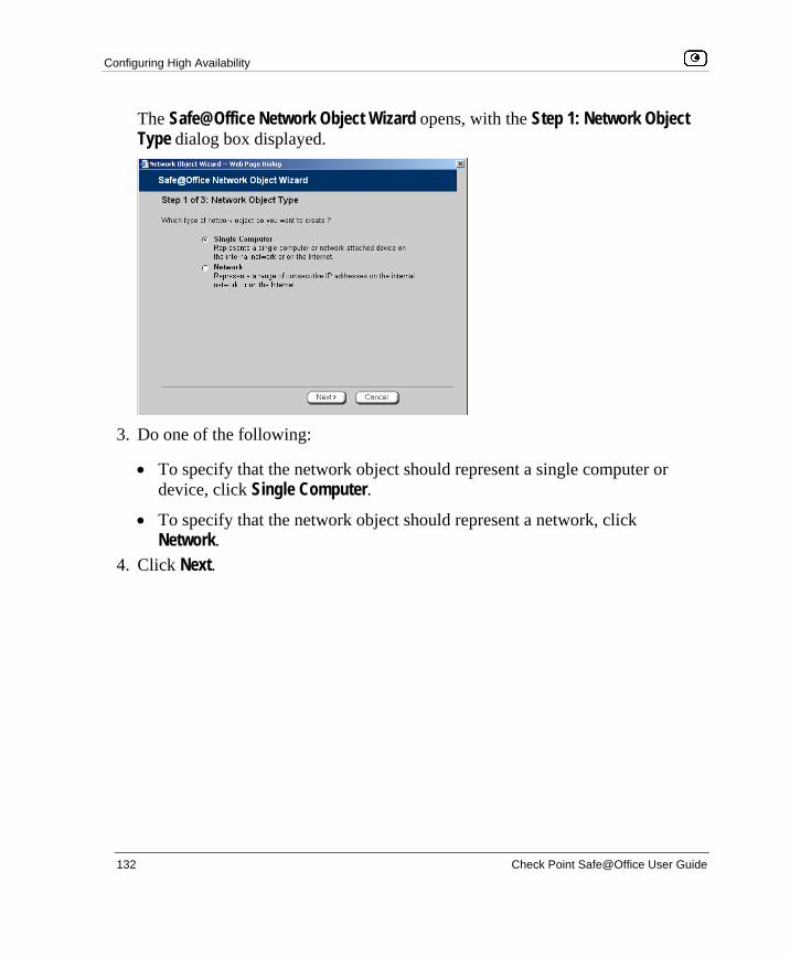
Configuring High Availability
132 Check Point Safe@Office User Guide
The Safe@Office Network Object Wizard opens, with the Step 1: Network Object Type dialog box displayed.
3. Do one of the following:
• To specify that the network object should represent a single computer or device, click Single Computer.
• To specify that the network object should represent a network, click Network.
4. Click Next.

Configuring High Availability
Chapter 5: Managing Your Network 133
The Step 2: Computer Details dialog box appears. If you chose Single Computer, the dialog box includes the Perform Static NAT option.
If you chose Network, the dialog box does not include this option.
5. Complete the fields using the information in the tables below.
6. Click Next.

Configuring High Availability
134 Check Point Safe@Office User Guide
The Step 3: Save dialog box appears.
7. Type a name for the network object in the field.
8. Click Finish.
To add or edit a network object via the Active Computers page
1. Click Reports in the main menu, and click the Active Computers tab.

Configuring High Availability
Chapter 5: Managing Your Network 135
The Active Computers page appears.
If a computer has not yet been added as a network object, the Add button appears next to it. If a computer has already been added as a network object, the Edit button appears next to it.
2. Do one of the following:
• To add a network object, click Add next to the desired computer.
• To edit a network object, click Edit next to the desired computer. The Safe@Office Network Object Wizard opens, with the Step 1: Network Object Type dialog box displayed.
3. Do one of the following:
• To specify that the network object should represent a single computer or device, click Single Computer.

Configuring High Availability
136 Check Point Safe@Office User Guide
• To specify that the network object should represent a network, click Network.
4. Click Next. The Step 2: Computer Details dialog box appears.
The computer's IP address and MAC address are automatically filled in.
5. Complete the fields using the information in the tables below.
6. Click Next. The Step 3: Save dialog box appears with the network object's name. If you are adding a new network object, this name is the computer's name.
7. To change the network object name, type the desired name in the field.
8. Click Finish.
The new object appears in the Network Objects page.

Configuring High Availability
Chapter 5: Managing Your Network 137
Table 16: Network Object Fields for a Single Computer
In this field… Do this…
IP Address Type the IP address of the local computer, or click This Computer to
specify your computer.
Reserve a fixed IP
address for this
computer
Select this option to assign the network object's IP address to a MAC
address, and to allow the network object to connect to the WLAN
when MAC Filtering is used. For information about MAC Filtering, see
Configuring a Wireless Network on page 161.
MAC Address Type the MAC address you want to assign to the network object's IP address, or click This Computer to specify your computer's MAC
address.
Perform Static NAT
(Network Address
Translation)
Select this option to map the local computer's IP address to an
Internet IP address.
You must then fill in the External IP field.
External IP Type the Internet IP address to which you want to map the local
computer's IP address.
Exclude this computer
from HotSpot
enforcement
Select this option to exclude the network object from HotSpot
enforcement.

Configuring High Availability
138 Check Point Safe@Office User Guide
Table 17: Network Object Fields for a Network
In this field… Do this…
IP Range Type the range of local computer IP addresses in the network.
Perform Static NAT
(Network Address
Translation)
Select this option to map the network's IP address range to a range of
Internet IP addresses of the same size.
You must then fill in the External IP Range field.
External IP Range Type the Internet IP address range to which you want to map the
network's IP address range.
Exclude this network
from HotSpot
enforcement
Select this option to exclude this network from HotSpot enforcement.
Viewing and Deleting Network Objects
To view or delete a network object
1. Click Network in the main menu, and click the Network Objects tab.
The Network Objects page appears with a list of network objects.
2. To delete a network object, do the following:
a. In the desired network object's row, click the Erase icon.
A confirmation message appears.
b. Click OK.
The network object is deleted.

Using Static Routes
Chapter 5: Managing Your Network 139
Using Static Routes
A static route is a setting that explicitly specifies the route for packets originating in a certain subnet and/or destined for a certain subnet. Packets with a source and destination that does not match any defined static route will be routed to the default gateway. To modify the default gateway, see Using a LAN Connection on page 65.
A static route can be based on the packet's destination IP address, or based on the source IP address, in which case it is a source route.
Source routing can be used, for example, for load balancing between two Internet connections. For example, if you have an Accounting department and a Marketing department, and you want each to use a different Internet connection for outgoing traffic, you can add a static route specifying that traffic originating from the Accounting department should be sent via WAN1, and another static route specifying that traffic originating from the Marketing department should be sent via WAN2.
The Static Routes page lists all existing routes, including the default, and indicates whether each route is currently "Up" (reachable) or not.
Adding and Editing Static Routes
To add a static route
1. Click Network in the main menu, and click the Routes tab.

Using Static Routes
140 Check Point Safe@Office User Guide
The Static Routes page appears, with a list of existing static routes.
2. Do one of the following:
• To add a static route, click New Route.
• To edit an existing static route, click Edit next to the desired route in the list.

Using Static Routes
Chapter 5: Managing Your Network 141
The Static Route Wizard opens displaying the Step 1: Source and Destination dialog box.
3. To select a specific source network (source routing), do the following:
a) In the Source drop-down list, select Specified Network.
New fields appear.
b) In the Network field, type the IP address of the source network.
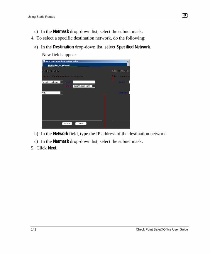
Using Static Routes
142 Check Point Safe@Office User Guide
c) In the Netmask drop-down list, select the subnet mask. 4. To select a specific destination network, do the following:
a) In the Destination drop-down list, select Specified Network.
New fields appear.
b) In the Network field, type the IP address of the destination network.
c) In the Netmask drop-down list, select the subnet mask. 5. Click Next.

Using Static Routes
Chapter 5: Managing Your Network 143
The Step 2: Next Hop and Metric dialog box appears.
6. In the Next Hop IP field, type the IP address of the gateway (next hop router) to
which to route the packets destined for this network.
7. In the Metric field, type the static route's metric.
The gateway sends a packet to the route that matches the packet's destination and has the lowest metric.
The default value is 10.
8. Click Next.

Using Static Routes
144 Check Point Safe@Office User Guide
The new static route is saved.
Viewing and Deleting Static Routes
Note: The “default” route cannot be deleted.
To delete a static route
1. Click Network in the main menu, and click the Routes tab.
The Static Routes page appears, with a list of existing static routes.
2. In the desired route row, click the Erase icon.
A confirmation message appears.
3. Click OK.
The route is deleted.

Managing Ports
Chapter 5: Managing Your Network 145
Managing Ports
The Safe@Office appliance enables you to quickly and easily assign its ports to different uses, as shown in the table below. Furthermore, you can restrict each port to a specific link speed and duplex setting.
Table 18: Ports and Assignments
You can assign this port... To these uses...
LAN LAN network
VLAN network
DMZ/WAN2 DMZ network
Second WAN connection
VLAN trunk
RS232 Dialup modem
Serial console

Managing Ports
146 Check Point Safe@Office User Guide
Viewing Port Statuses
You can view the status of the Safe@Office appliance's ports on the Ports page, including each Ethernet connection's duplex state. This is useful if you need to check whether the appliance's physical connections are working, and you can’t see the LEDs on front of the appliance.
Note: In the Safe@Office 500 model SBX-166LHG-2, status information is only available for the WAN and DMZ ports, and not for LAN ports 1-4.
To view port statuses
1. Click Network in the main menu, and click the Ports tab.
The Ports page appears.
The following information is displayed for each enabled port:

Managing Ports
Chapter 5: Managing Your Network 147
• Assign To. The port's current assignment. For example, if the DMZ/WAN2 port is currently used for the DMZ, the drop-down list displays "DMZ".
• Link Configuration. The configured link speed (10 Mbps or 100 Mbps) and duplex (Full Duplex or Half Duplex) configured for the port.
Automatic Detection indicates that the port is configured to automatically detect the link speed and duplex.
• Status. The detected link speed and duplex.
No Link indicates that the appliance does not detect anything connected to the port.
Disabled indicates that the port is disabled. For example, if the DMZ/WAN2 port is currently assigned to the DMZ, but the DMZ is disabled, the port is marked as such.
2. To refresh the display, click Refresh.
Modifying Port Assignments
You can assign ports to different networks or purposes. Since modifying port assignments often requires additional configurations, use the table below to determine which procedure you should use:
Table 19: Modifying Port Assignments
To assign a port to...
See...
LAN The procedure below
VLAN or
VLAN Trunk
Configuring VLANs on page 111

Managing Ports
148 Check Point Safe@Office User Guide
To assign a port to...
See...
WAN2 Setting Up a LAN or Broadband Backup Connection on page 91
DMZ Configuring a DMZ Network
Console Using a Console on page 390
Modem Setting Up a Dialup Modem on page 84
To modify a port assignment
1. Click Network in the main menu, and click the Ports tab.
The Ports page appears.
In the Assigned To drop-down list to the right of the port, select the desired port assignment.
2. Click Apply.
The port is reassigned to the specified network or purpose.

Managing Ports
Chapter 5: Managing Your Network 149
Modifying Link Configurations
By default, the Safe@Office automatically detects the link speed and duplex. If desired, you can manually restrict the Safe@Office appliance's ports to a specific link speed and duplex.
Note: In the Safe@Office 500 model SBX-166LHG-2, restricting the link speed and duplex is available for the WAN and DMZ ports, and not for LAN ports 1-4.
To modify a port's link configuration
1. Click Network in the main menu, and click the Ports tab.
The Ports page appears.
2. In the Link Configuration drop-down list to the right of the port, do one of the following:
• Select the desired link speed and duplex.
• Select Automatic Detection to configure the port to automatically detect the link speed and duplex.
This is the default. 3. Click Apply.
The port uses the specified link speed and duplex.

Managing Ports
150 Check Point Safe@Office User Guide
Resetting Ports to Defaults
You can reset the Safe@Office appliance's ports to their default link configurations ("Automatic Detection") and default assignments (shown in the table below).
Table 20: Default Port Assignments
Port Default Assignment
1-4 LAN
DMZ / WAN2 DMZ
WAN This port is always assigned to the WAN.
RS232 Modem
To reset ports to defaults
1. Click Network in the main menu, and click the Ports tab.
The Ports page appears.
2. Click Default. A confirmation message appears.
3. Click OK.
The ports are reset to their default assignments and to "Automatic Detection" link configuration.
All currently-established connections that are not supported by the default settings may be broken. For example, if you were using the DMZ/WAN2 port as WAN2, the port reverts to its DMZ assignment, and the secondary Internet connection moves to the WAN port.

Overview
Chapter 6: Using Traffic Shaper 151
Chapter 6
This chapter describes how to use Traffic Shaper to control the flow of communication to and from your network.
This chapter includes the following topics: Overview ..................................................................................................151 Setting Up Traffic Shaper.........................................................................153 Predefined QoS Classes............................................................................154 Adding and Editing Classes......................................................................155 Deleting Classes .......................................................................................159 Restoring Traffic Shaper Defaults ............................................................160
Overview Traffic Shaper is a bandwidth management solution that allows you to set bandwidth policies to control the flow of communication. Traffic Shaper ensures that important traffic takes precedence over less important traffic, so that your business can continue to function with minimum disruption, despite network congestion.
Traffic Shaper uses Stateful Inspection technology to access and analyze data derived from all communication layers. This data is used to classify traffic in Quality of Service (QoS) classes. Traffic Shaper divides available bandwidth among the classes according to weight. For example, suppose Web traffic is deemed three times as important as FTP traffic, and these services are assigned weights of 30 and 10 respectively. If the lines are congested, Traffic Shaper will maintain the ratio of bandwidth allocated to Web traffic and FTP traffic at 3:1.
If a specific class is not using all of its bandwidth, the leftover bandwidth is divided

Overview
152 Check Point Safe@Office User Guide
bandwidth, and the FTP connection will receive 25% (10/40) of the leftover bandwidth. If the Web connection closes, the FTP connection will receive 100% of the bandwidth.
Each class has a bandwidth limit, which is the maximum amount of bandwidth that connections belonging to that class may use together. Once a class has reached its bandwidth limit, connections belonging to that class will not be allocated further bandwidth, even if there is unused bandwidth available. For example, traffic used by Peer-To-Peer file-sharing applications may be limited to a specific rate, such as 512 kilobit per second. Each class also has a “Delay Sensitivity” value, indicating whether connections belonging to the class should be given precedence over connections belonging to other classes.
Your Safe@Office appliance offers different degrees of traffic shaping, depending on its model:
• Simplified Traffic Shaper. Includes a fixed set of four predefined classes. You can assign network traffic to each class, but you cannot modify the classes, delete them, or create new classes. Available in Safe@Office 500.
• Advanced Traffic Shaper. Includes a set of four predefined classes, but enables you to modify the classes, delete them, and create new classes. You can define up to eight classes, including weight, bandwidth limits, and DiffServ (Differentiated Services) Packet Marking parameters. DiffServ marks packets as belonging to a certain Quality of Service class. These packets are then granted priority on the public network according to their class. Available in Safe@Office 500 with Power Pack.
Note: You can prioritize wireless traffic from WMM-compliant multimedia applications, by enabling Wireless Multimedia (WMM) for the WLAN network. See Manually Configuring a WLAN on page 165.

Setting Up Traffic Shaper
Chapter 6: Using Traffic Shaper 153
Setting Up Traffic Shaper
To set up Traffic Shaper
1. Enable Traffic Shaper for the Internet connection, using the procedure Using Internet Setup on page 63.
You can enable Traffic Shaper for incoming or outgoing connections.
• When enabling Traffic Shaper for outgoing traffic:
Specify a rate (in kilobits/second) slightly lower than your Internet connection's maximum measured upstream speed.
• When enabling Traffic Shaper for incoming traffic:
Specify a rate (in kilobits/second) slightly lower than your Internet connection's maximum measured downstream speed.
It is recommended to try different rates in order to determine which ones provide the best results.
Note: Traffic Shaper cannot control the number or type of packets it receives from the Internet; it can only affect the rate of incoming traffic by dropping received packets. This makes the shaping of inbound traffic less accurate than the shaping of outbound traffic. It is therefore recommended to enable traffic shaping for incoming traffic only if necessary.
2. If you are using Safe@Office 500 with Power Pack, you can add QoS classes that reflect your communication needs, or modify the four predefined QoS classes.
See Adding and Editing Classes on page 155.
Note: If you are using Safe@Office 500, you have Simplified Traffic Shaper, and you cannot add or modify the classes. To add or modify classes, upgrade to Safe@Office 500 with Power Pack, which supports Advanced Traffic Shaper.

Predefined QoS Classes
154 Check Point Safe@Office User Guide
3. Use Allow or Allow and Forward rules to assign different types of connections to QoS classes.
For example, if Traffic Shaper is enabled for outgoing traffic, and you create an Allow rule associating all outgoing VPN traffic with the Urgent QoS class, then Traffic Shaper will handle outgoing VPN traffic as specified in the bandwidth policy for the Urgent class.
See Adding and Editing Rules on page 213.
Note: Traffic Shaper must be enabled for the direction of traffic specified in the rule.
Note: If you do not assign a connection type to a class, Traffic Shaper automatically assigns the connection type to the predefined "Default" class.
Predefined QoS Classes
Traffic Shaper provides the following predefined QoS classes.
To assign traffic to these classes, define firewall rules as described in Using Rules on page 209.
Table 21: Predefined QoS Classes
Class Weight Delay Sensitivity Useful for
Default 10 Medium
(Normal Traffic)
Normal traffic.
All traffic is assigned to this class by default.
Urgent 15 High
(Interactive Traffic)
Traffic that is highly sensitive to delay. For
example, IP telephony, videoconferencing,
and interactive protocols that require quick
user response, such as telnet.

Adding and Editing Classes
Chapter 6: Using Traffic Shaper 155
Class Weight Delay Sensitivity Useful for
Important 20 Medium
(Normal Traffic)
Normal traffic
Low Priority 5 Low
(Bulk Traffic)
Traffic that is not sensitive to long delays. For
example, SMTP traffic (outgoing email).
In Simplified Traffic Shaper, these classes cannot be changed.
Adding and Editing Classes
To add or edit a QoS class
1. Click Network in the main menu, and click the Traffic Shaper tab.
The Quality of Service Classes page appears.
2. Click Add.

Adding and Editing Classes
156 Check Point Safe@Office User Guide
The Safe@Office QoS Class Editor wizard opens, with the Step 1 of 3: Quality of Service Parameters dialog box displayed.
3. Complete the fields using the relevant information in the table below.
4. Click Next. The Step 2 of 3: Advanced Options dialog box appears.
5. Complete the fields using the relevant information in the table below.

Adding and Editing Classes
Chapter 6: Using Traffic Shaper 157
Note: Traffic Shaper may not enforce guaranteed rates and relative weights for incoming traffic as accurately as for outgoing traffic. This is because Traffic Shaper cannot control the number or type of packets it receives from the Internet; it can only affect the rate of incoming traffic by dropping received packets. It is therefore recommended to enable traffic shaping for incoming traffic only if necessary. For information on enabling Traffic Shaper for incoming and outgoing traffic, see Using Internet Setup on page 63.
6. Click Next. The Step 3 of 3: Save dialog box appears with a summary of the class.
7. Type a name for the class.
For example, if you are creating a class for high priority Web connections, you can name the class "High Priority Web".
8. Click Finish.
The new class appears in the Quality of Service Classes page.

Adding and Editing Classes
158 Check Point Safe@Office User Guide
Table 22: QoS Class Fields
In this field… Do this…
Relative Weight Type a value indicating the class's importance relative to the other
defined classes.
For example, if you assign one class a weight of 100, and you assign
another class a weight of 50, the first class will be allocated twice the
amount of bandwidth as the second when the lines are congested.
Delay Sensitivity Select the degree of precedence to give this class in the transmission
queue:
• Low (Bulk Traffic) - Traffic that is not sensitive to long delays. For example, SMTP traffic (outgoing email).
• Medium (Normal Traffic) - Normal traffic • High (Interactive Traffic) - Traffic that is highly sensitive to delay.
For example, IP telephony, videoconferencing, and interactive protocols that require quick user response, such as telnet.
Traffic Shaper serves delay-sensitive traffic with a lower latency. That is,
Traffic Shaper attempts to send packets with a "High (Interactive Traffic)"
level before packets with a "Medium (Normal Traffic)" or "Low (Bulk
Traffic)" level.
Outgoing Traffic:
Guarantee At
Least
Select this option to guarantee a minimum bandwidth for outgoing traffic
belonging to this class. Then type the minimum bandwidth (in
kilobits/second) in the field provided.
Outgoing Traffic:
Limit rate to
Select this option to limit the rate of outgoing traffic belonging to this
class. Then type the maximum rate (in kilobits/second) in the field
provided.
Incoming Traffic:
Guarantee At
Least
Select this option to guarantee a minimum bandwidth for incoming traffic
belonging to this class. Then type the minimum bandwidth (in
kilobits/second) in the field provided.

Deleting Classes
Chapter 6: Using Traffic Shaper 159
In this field… Do this…
Incoming Traffic:
Limit rate to
Select this option to limit the rate of incoming traffic belonging to this
class. Then type the maximum rate (in kilobits/second) in the field
provided.
DiffServ Code
Point
Select this option to mark packets belonging to this class with a DiffServ
Code Point (DSCP), which is an integer between 0 and 63. Then type the
DSCP in the field provided.
The marked packets will be given priority on the public network according
to their DSCP.
To use this option, your ISP or private WAN must support DiffServ. You
can obtain the correct DSCP value from your ISP or private WAN
administrator.
Deleting Classes
You cannot delete a class that is currently used by a rule. You can determine whether a class is in use or not, by viewing the Rules page.
To delete an existing QoS class
1. Click Network in the main menu, and click the Traffic Shaper tab.
The Quality of Service Classes page appears.
2. Click the Erase icon of the class you wish to delete.
A confirmation message appears.
3. Click OK.
The class is deleted.

Restoring Traffic Shaper Defaults
160 Check Point Safe@Office User Guide
Restoring Traffic Shaper Defaults
If desired, you can reset the Traffic Shaper bandwidth policy to use the four predefined classes, and restore these classes to their default settings. For information on these classes and their defaults, see Predefined QoS Classes on page 154.
Note: This will delete any additional classes you defined in Traffic Shaper and reset all rules to use the Default class.
If one of the additional classes is currently used by a rule, you cannot reset Traffic Shaper to defaults. You can determine whether a class is in use or not, by viewing the Rules page.
To restore Traffic Shaper defaults
1. Click Network in the main menu, and click the Traffic Shaper tab.
The Quality of Service Classes page appears.
2. Click Restore Defaults.
A confirmation message appears.
3. Click OK.

Overview
Chapter 7: Configuring a Wireless Network 161
Chapter 7
This chapter describes how to set up a wireless internal network.
This chapter includes the following topics: Overview ..................................................................................................161 About the Wireless Hardware in Your Safe@Office 500W Appliance ...162 Wireless Security Protocols......................................................................163 Manually Configuring a WLAN...............................................................165 Using the Wireless Configuration Wizard................................................176 Preparing the Wireless Stations................................................................182 Troubleshooting Wireless Connectivity ...................................................183
Overview In addition to the LAN and DMZ networks, you can define a wireless internal network called a WLAN (wireless LAN) network, when using Safe@Office 500W.
For information on default security policy rules controlling traffic to and from the WLAN, see Default Security Policy on page 203.
You can configure a WLAN network in either of the following ways:
• Wireless Configuration Wizard. Guides you through the WLAN setup step by step.
See Using the Wireless Configuration Wizard on page 176.
• Manual configuration. Offers advanced setup options.
See Manually Configuring a WLAN on page 165.
Note: It is recommended to configure the WLAN via Ethernet and not via a wireless connection, because the wireless connection could be broken after making a change to the configuration.
Configuring a Wireless Network
About the Wireless Hardware in Your Safe@Office 500W Appliance
162 Check Point Safe@Office User Guide
About the Wireless Hardware in Your Safe@Office 500W Appliance
Your Safe@Office 500W appliance features a built-in 802.11b/g access point that is tightly integrated with the firewall and hardware-accelerated VPN.
Safe@Office 500W supports the latest 802.11g standard (up to 54Mbps) and is backwards compatible with the older 802.11b standard (up to 11Mbps), so that both new and old adapters of these standards are interoperable. Safe@Office 500W also supports a special Super G mode that allows reaching a throughput of up to 108Mbps with Super G compatible stations. For more information on the Super G mode refer to: http://www.super-ag.com.
Safe@Office 500W transmits in 2.4GHz range, using dual diversity antennas to increase the range. In addition, the Safe@Office 500W supports a special extended range (XR) mode that allows up to three times the range of a regular 802.11g access point. XR dramatically stretches the performance of a wireless LAN, by enabling long-range connections. The architecture delivers receive sensitivities of up to 105dBm, over 20 dB more than the 802.11 specification. This allows ranges of up to 300 meters indoors, and up to 1 km (3200 ft) outdoors, with XR-enabled wireless stations (actual range depends on environment).
Wireless Security Protocols
Chapter 7: Configuring a Wireless Network 163
Wireless Security Protocols The Safe@Office wireless security appliance supports the following security protocols:
Table 23: Wireless Security Protocols
Security Protocol
Description
None No security method is used. This option is not recommended, because it
allows unauthorized users to access your WLAN network, although you can
still limit access from the WLAN by creating firewall rules. This method is
suitable for creating public access points.
WEP encryption In the WEP (Wired Equivalent Privacy) encryption security method, wireless
stations must use a pre-shared key to connect to your network. This method
is not recommended, due to known security flaws in the WEP protocol. It is
provided for compatibility with existing wireless deployments.
Note: The appliance and the wireless stations must be configured with the
same WEP key.
802.1X: RADIUS
authentication, no
encryption
In the 802.1x security method, wireless stations (supplicants) attempting to
connect to the access point (authenticator) must first be authenticated by a
RADIUS server (authentication server) which supports 802.1x . All messages
are passed in EAP (Extensible Authentication Protocol).
This method is recommended for situations in which you want to authenticate
wireless users, but do not need to encrypt the data.
Note: To use this security method, you must first configure a RADIUS server.
See Using RADIUS Authentication. on page 370

Wireless Security Protocols
164 Check Point Safe@Office User Guide
Security Protocol
Description
WPA: RADIUS
authentication,
encryption
The WPA (Wi-Fi Protected Access) security method uses MIC (message
integrity check) to ensure the integrity of messages, and TKIP (Temporal Key
Integrity Protocol) to enhance data encryption.
Furthermore, WPA includes 802.1x and EAP authentication, based on a
central RADIUS authentication server. This method is recommended for
situations where you want to authenticate wireless stations using a RADIUS
server, and to encrypt the transmitted data.
Note: To use this security method, you must first configure a RADIUS server
which supports 802.1x. See Using RADIUS Authentication. on page 370
WPA-PSK:
password
authentication,
encryption
The WPA-PSK security method is a variation of WPA that does not require an
authentication server. WPA-PSK periodically changes and authenticates
encryption keys. This is called rekeying.
This option is recommended for small networks, which want to authenticate
and encrypt wireless data, but do not want to install a RADIUS server.
Note: The appliance and the wireless stations must be configured with the
same passphrase.
WPA2 (802.11i) The WPA2 security method uses the more secure Advanced Encryption
Standard (AES) cipher, instead of the RC4 cipher used by WPA and WEP.
When using WPA or WPA-PSK security methods, the Safe@Office enables
you to restrict access to the WLAN network to wireless stations that support
the WPA2 security method. If this setting is not selected, the Safe@Office
appliance allows clients to connect using both WPA and WPA2.

Manually Configuring a WLAN
Chapter 7: Configuring a Wireless Network 165
Note: For increased security, it is recommended to enable the Safe@Office internal VPN Server for users connecting from your internal networks, and to install SecuRemote on each computer in the WLAN. This ensures that all connections from the WLAN to the LAN are encrypted and authenticated. For information, see Internal VPN Server on page 306 and Setting Up Your Safe@Office Appliance as a VPN Server on page 307.
Manually Configuring a WLAN
To manually configure a WLAN network
1. Prepare the appliance for a wireless connection as described in Network Installation on page 35.
2. If you want to use 802.1X or WPA security mode for the WLAN, configure a RADIUS server.
For information on security modes, see Basic WLAN Settings Fields on page 168.
For information on configuring RADIUS servers, see Using RADIUS Authentication on page 370.
3. Click Network in the main menu, and click the My Network tab.
The My Network page appears.
4. In the WLAN network's row, click Edit.

Manually Configuring a WLAN
166 Check Point Safe@Office User Guide
The Edit Network Settings page appears.
5. In the Mode drop-down list, select Enabled.
The fields are enabled.
6. If desired, enable or disable Hide NAT.
See Enabling/Disabling Hide NAT on page 107.
7. If desired, configure a DHCP server.
See Configuring a DHCP Server on page 94.

Manually Configuring a WLAN
Chapter 7: Configuring a Wireless Network 167
8. Complete the fields using the information in Basic WLAN Settings Fields on page 168.
9. To configure advanced settings, click Show Advanced Settings and complete the fields using the information in Advanced WLAN Settings Fields on page 172.
New fields appear.
10. Click Apply.
A warning message appears, telling you that you are about to change your network settings.

Manually Configuring a WLAN
168 Check Point Safe@Office User Guide
11. Click OK.
A success message appears.
12. Prepare the wireless stations.
See Preparing the Wireless Stations on page 182.
Table 24: WLAN Settings Fields
In this field… Do this…
IP Address Type the IP address of the WLAN network's default gateway.
Note: The WLAN network must not overlap other networks.
Subnet Mask Type the WLAN’s internal network range.
Wireless Settings
Network Name
(SSID)
Type the network name (SSID) that identifies your wireless network. This
name will be visible to wireless stations passing near your access point, unless you enable the Hide the Network Name (SSID) option.
It can be up to 32 alphanumeric characters long and is case-sensitive.
Country Select the country where you are located.
Warning: Choosing an incorrect country may result in the violation of
government regulations.

Manually Configuring a WLAN
Chapter 7: Configuring a Wireless Network 169
In this field… Do this…
Operation Mode Select an operation mode:
• 802.11b (11Mbps). Operates in the 2.4 GHz range and offers a maximum theoretical rate of 11 Mbps. When using this mode, only 802.11b stations will be able to connect.
• 802.11g (54 Mbps). Operates in the 2.4 GHz range, and offers a maximum theoretical rate of 54 Mbps. When using this mode, only 802.11g stations will be able to connect.
• 802.11b/g (11/54 Mbps). Operates in the 2.4 GHz range, and offers a maximum theoretical rate of 54 Mbps. When using this mode, both 802.11b stations and 802.11g stations will be able to connect.
• 802.11g Super (108 Mbps). Operates in the 2.4 GHz range, and offers a maximum theoretical rate of 108 Mbps. When using this mode, only 802.11g Super stations will be able to connect.
• 802.11g Super (11/54/108). Operates in the 2.4 GHz range, and offers a maximum theoretical rate of 108 Mbps. When using this mode, 802.11b stations, 802.11g stations, and 802.11g Super stations will all be able to connect.
Each operation mode indicates a wireless protocol (such as 802.11g
Super), followed by the maximum bandwidth (such as 108 Mbps).
The list of modes is dependent on the selected country.
You can prevent older wireless stations from slowing down your network, by
choosing an operation mode that restricts access to newer wireless
stations.
Note: The actual data transfer speed is usually significantly lower than the
maximum theoretical bandwidth and degrades with distance.
Important: The station wireless cards must support the selected operation
mode. For a list of cards supporting 802.11g Super, refer to
http://www.super-ag.com.

Manually Configuring a WLAN
170 Check Point Safe@Office User Guide
In this field… Do this…
Channel Select the radio frequency to use for the wireless connection:
• Automatic. The Safe@Office appliance automatically selects a channel. This is the default.
• A specific channel. The list of channels is dependent on the selected country and operation mode.
Note: If there is another wireless network in the vicinity, the two networks
may interfere with one another. To avoid this problem, the networks should
be assigned channels that are at least 25 MHz (5 channels) apart.
Alternatively, you can reduce the transmission power.
Security Select the security protocol to use. For information on the supported
security protocols, see Wireless Security Protocols on page 163.
If you select WEP encryption, the WEP Keys area opens.
If you select WPA, the Require WPA2 (802.11i) field appears.
If you select WPA-PSK, the Passphrase and Require WPA2 (802.11i) fields
appear.
Passphrase Type the passphrase for accessing the network, or click Random to randomly
generate a passphrase.
This must be between 8 and 63 characters. It can contain spaces and
special characters, and is case-sensitive.
For the highest security, choose a long passphrase that is hard to guess, or use the Random button.
Note: The wireless stations must be configured with this passphrase as well.

Manually Configuring a WLAN
Chapter 7: Configuring a Wireless Network 171
In this field… Do this…
Require WPA2
(802.11i)
Specify whether you want to require wireless stations to connect using
WPA2, by selecting one of the following:
• Enable. Only wireless stations using WPA2 can access the WLAN network.
• Disable. Wireless stations using either WPA or WPA2 can access the WLAN network. This is the default.
WEP Keys If you selected WEP encryption, you must configure at least one WEP key.
The wireless stations must be configured with the same key, as well.
Key 1, 2, 3, 4 radio
button
Click the radio button next to the WEP key that this gateway should use for
transmission.
The selected key must be entered in the same key slot (1-4) on the station
devices, but the key need not be selected as the transmit key on the
stations.
Note: You can use all four keys to receive data.
Key 1, 2, 3, 4
length Select the WEP key length from the drop-down list.
The possible key lengths are:
• 64 Bits. The key length is 10 characters. • 128 Bits. The key length is 26 characters. • 152 Bits. The key length is 32 characters.
Note: Some wireless card vendors call these lengths 40/104/128,
respectively.
Note: WEP is generally considered to be insecure, regardless of the
selected key length.

Manually Configuring a WLAN
172 Check Point Safe@Office User Guide
In this field… Do this…
Key 1, 2, 3, 4 text
box
Type the WEP key, or click Random to randomly generate a key matching
the selected length. The key is composed of hexadecimal characters 0-9
and A-F, and is not case-sensitive.
Table 25: Advanced WLAN Settings Fields
In this field… Do this…
Advanced Security
Hide the Network
Name (SSID)
Specify whether you want to hide your network's SSID, by selecting one of
the following:
• Yes. Hide the SSID. Only devices to which your SSID is known can connect to your network.
• No. Do not hide the SSID. Any device within range can detect your network name using the wireless network discovery features of some products, such as Microsoft Windows XP, and attempt to connect to your network. This is the default.
Note: Hiding the SSID does not provide strong security, because by a
determined attacker can still discover your SSID. Therefore, it is not
recommended to rely on this setting alone for security.

Manually Configuring a WLAN
Chapter 7: Configuring a Wireless Network 173
In this field… Do this…
MAC Address
Filtering
Specify whether you want to enable MAC address filtering, by selecting one
of the following:
• Yes. Enable MAC address filtering. Only MAC addresses that you added as network objects can connect to your network. For information on network objects, see Using Network Objects on page 129.
• No. Disable MAC address filtering. This is the default.
Note: MAC address filtering does not provide strong security, since MAC
addresses can be spoofed by a determined attacker. Therefore, it is not
recommended to rely on this setting alone for security.
Wireless Transmitter
Transmission Rate Select the transmission rate:
• Automatic. The Safe@Office appliance automatically selects a rate. This is the default.
• A specific rate
Transmitter Power Select the transmitter power.
Setting a higher transmitter power increases the access point's range. A
lower power reduces interference with other access points in the vicinity.
The default value is Full. It is not necessary to change this value, unless
there are other access points in the vicinity.

Manually Configuring a WLAN
174 Check Point Safe@Office User Guide
In this field… Do this…
Antenna Selection Multipath distortion is caused by the reflection of Radio Frequency (RF)
signals traveling from the transmitter to the receiver along more than one
path. Signals that were reflected by some surface reach the receiver after
non-reflected signals and distort them.
Safe@Office appliances avoid the problems of multipath distortion by using
an antenna diversity system. To provide antenna diversity, each wireless
security appliance has two antennas.
Specify which antenna to use for communicating with wireless stations:
• Automatic. The Safe@Office appliance receives signals through both antennas and automatically selects the antenna with the lowest distortion signal to use for communicating. The selection is made on a per-station basis. This is the default.
• ANT 1. The ANT 1antenna is always used for communicating. • ANT 2. The ANT 2 antenna is always used for communicating.
Use manual diversity control (ANT 1 or ANT 2), if there is only one antenna
connected to the appliance.
Fragmentation
Threshold
Type the smallest IP packet size (in bytes) that requires that the IP packet
be split into smaller fragments.
If you are experiencing significant radio interference, set the threshold to a
low value (around 1000), to reduce error penalty and increase overall
throughput.
Otherwise, set the threshold to a high value (around 2000), to reduce
overhead.
The default value is 2346.

Manually Configuring a WLAN
Chapter 7: Configuring a Wireless Network 175
In this field… Do this…
RTS Threshold Type the smallest IP packet size for which a station must send an RTS
(Request To Send) before sending the IP packet.
If multiple wireless stations are in range of the access point, but not in range
of each other, they might send data to the access point simultaneously,
thereby causing data collisions and failures. RTS ensures that the channel
is clear before the each packet is sent.
If your network is congested, and the users are distant from one another,
set the RTS threshold to a low value (around 500).
Setting a value equal to the fragmentation threshold effectively disables
RTS.
The default value is 2346.
Extended Range
Mode (XR)
Specify whether to use Extended Range (XR) mode:
• Disabled. XR mode is disabled. • Enabled. XR mode is enabled. XR will be automatically
negotiated with XR-enabled wireless stations and used as needed. This is the default.
For more information on XR mode, see About the Wireless Hardware in Your Safe@Office 500W Appliance on page 162.
Multimedia QoS
(WMM)
Specify whether to use the Wireless Multimedia (WMM) standard to
prioritize traffic from WMM-compliant multimedia applications:
• Disabled. WMM is disabled. This is the default. • Enabled. WMM is enabled. The Safe@Office appliance will
prioritize multimedia traffic according to four access categories (Voice, Video, Best Effort, and Background). This allows for smoother streaming of voice and video when using WMM aware applications.

Using the Wireless Configuration Wizard
176 Check Point Safe@Office User Guide
Using the Wireless Configuration Wizard
The Wireless Configuration Wizard provides a quick and simple way of setting up your basic WLAN parameters for the first time.
To configure a WLAN using the Wireless Configuration Wizard
1. Prepare the appliance for a wireless connection as described in Network Installation on page 35.
2. Click Network in the main menu, and click the My Network tab.
The My Network page appears.
3. In the WLAN network's row, click Edit. The Edit Network Settings page appears.
4. Click Wireless Wizard.
The Wireless Configuration Wizard opens, with the Wireless Configuration dialog box displayed.
5. Select the Enable wireless networking check box to enable the WLAN.

Using the Wireless Configuration Wizard
Chapter 7: Configuring a Wireless Network 177
The fields are enabled.
6. Complete the fields using the information in Basic WLAN Settings Fields on page 168.
7. Click Next. 8. The Wireless Security dialog box appears.
9. Do one of the following:
• Click WPA-PSK to use the WPA-PSK security mode.
WPA-PSK periodically changes and authenticates encryption keys. This is a recommended security mode for small, private wireless networks, which want to authenticate and encrypt wireless data but do not want to install a RADIUS server. Both WPA and the newer, more secure WPA2 (802.11i) will be accepted.
• Click WEP to use the WEP security mode.
Using WEP, wireless stations must use a pre-shared key to connect to your network. WEP is widely known to be insecure, and is supported mainly for compatibility with existing networks and stations that do not support other methods.

Using the Wireless Configuration Wizard
178 Check Point Safe@Office User Guide
• Click No Security to use no security to create a public, unsecured access point.
Note: You cannot configure WPA and 802.1x using this wizard. For information on configuring these modes, see Manually Configuring a WLAN on page 165.
10. Click Next.
WPA-PSK If you chose WPA-PSK, the Wireless Configuration-WPA-PSK dialog box appears.
Do the following:
1. In the text box, type the passphrase for accessing the network, or click Random to randomly generate a passphrase.
This must be between 8 and 63 characters. It can contain spaces and special characters, and is case-sensitive.
2. Click Next.

Using the Wireless Configuration Wizard
Chapter 7: Configuring a Wireless Network 179
The Wireless Security Confirmation dialog box appears.
3. Click Next. 4. The Wireless Security Complete dialog box appears.
5. Click Finish.
The wizard closes.
6. Prepare the wireless stations.

Using the Wireless Configuration Wizard
180 Check Point Safe@Office User Guide
See Preparing the Wireless Stations on page 182.
WEP If you chose WEP, the Wireless Configuration-WEP dialog box appears.
Do the following:
1. Choose a WEP key length.
The possible key lengths are:
• 64 Bits - The key length is 10 hexadecimal characters.
• 128 Bits - The key length is 26 hexadecimal characters.
• 152 Bits - The key length is 32 hexadecimal characters. Some wireless card vendors call these lengths 40/104/128, respectively.
Note that WEP is generally considered to be insecure, regardless of the selected key length.
2. In the text box, type the WEP key, or click Random to randomly generate a key matching the selected length.
The key is composed of characters 0-9 and A-F, and is not case-sensitive. The wireless stations must be configured with this same key.

Using the Wireless Configuration Wizard
Chapter 7: Configuring a Wireless Network 181
3. Click Next. The Wireless Security Confirmation dialog box appears.
4. Click Next. The Wireless Security Complete dialog box appears.
5. Click Finish.
The wizard closes.
6. Prepare the wireless stations.
See Preparing the Wireless Stations on page 182.
No Security The Wireless Security Complete dialog box appears.
• Click Finish.
The wizard closes.
Preparing the Wireless Stations
182 Check Point Safe@Office User Guide
Preparing the Wireless Stations
After you have configured a WLAN, the wireless stations must be prepared for connection to the WLAN.
To prepare the wireless stations
1. If you selected the WEP security mode, give the WEP key to the wireless stations' administrators.
2. If you selected the WPA-PSK security mode, give the passphrase to the wireless stations' administrator.
3. The wireless stations' administrators should configure the wireless stations and connect them to the WLAN.
Refer to the wireless cards' documentation for details.
Note: Some wireless cards have "Infrastructure" and "Ad-hoc" modes. These modes are also called "Access Point" and "Peer to Peer". Choose the "Infrastructure" or "Access Point" mode. You can set the wireless cards to either "Long Preamble" or "Short Preamble".
Note: The wireless cards' region and the Safe@Office appliance's region must both match the region of the world where you are located. If you purchased your Safe@Office appliance in a different region, contact technical support.

Troubleshooting Wireless Connectivity
Chapter 7: Configuring a Wireless Network 183
Troubleshooting Wireless Connectivity I cannot connect to the WLAN from a wireless station. What should I do? • Check that the SSID configured on the station matches the Safe@Office
appliance's SSID. The SSID is case-sensitive.
• Check that the encryption settings configured on the station (encryption mode and keys) match the Safe@Office appliance's encryption settings.
• If MAC filtering is enabled, verify that the MAC address of all stations is listed in the Network Objects page (see Viewing and Deleting Network Objects on page 138).
How do I test wireless reception? • Look at the Wireless page, and check for excessive errors or dropped
packets.
• Look at the Active Computers page, to see information for specific wireless stations, such as the number of transmission errors, and the current reception power of each station.
• On the wireless station, open a command window and type ping my.firewall. If you see a large number of dropped packets, you are experiencing poor reception.
Wireless reception is poor. What should I do? • Adjust the angle of the antennas, until the reception improves. The
antennas radiate horizontally in all directions.
• If both antennas are connected to the Safe@Office appliance, check that the Antenna Selection parameter in the WLAN's advanced settings is set to Automatic (see Manually Configuring a WLAN on page 165).
• Relocate the Safe@Office appliance to a place with better reception, and avoid obstructions, such as walls and electrical equipment. For example, try mounting the appliance in a high place with a direct line of sight to the wireless stations.
• Check for interference with nearby electrical equipment, such as microwave ovens and cordless or cellular phones.


Troubleshooting Wireless Connectivity
Chapter 7: Configuring a Wireless Network 185
In addition, try setting the Fragmentation Threshold parameter in the WLAN's advanced settings (see Manually Configuring a WLAN on page 165) to a lower value. This will cause stations to fragment IP packets of a certain size into smaller packets, thereby reducing the likeliness of collisions and increasing network speed.
Note: Reducing the RTS Threshold and the Fragmentation Threshold too much can have a negative impact on performance.
Note: Setting an RTS Threshold value equal to the Fragmentation Threshold value effectively disables RTS.
I am not getting the full speed. What should I do? • The actual speed is always less then the theoretical speed, and degrades
with distance.
• Read the section about reception problems. Better reception means better speed.
• Check that all your wireless stations support the wireless standard you are using (802.11g or 802.11g Super), and that this standard is enabled in the station software. Transmission speed is determined by the slowest station associated with the access point. For a list of wireless stations that support 802.11g Super, see www.super-ag.com.


Viewing the Event Log
Chapter 8: Viewing Reports 187
Chapter 8
This chapter describes the Safe@Office Portal reports.
This chapter includes the following topics: Viewing the Event Log.............................................................................187 Using the Traffic Monitor ........................................................................191 Viewing Computers..................................................................................194 Viewing Connections ...............................................................................197 Viewing Wireless Statistics ......................................................................198
Viewing the Event Log
You can track network activity using the Event Log. The Event Log displays the most recent events and color-codes them.
Table 26: Event Log Color Coding
An event marked in this color…
Indicates…
Blue Changes in your setup that you have made yourself or as a result of
a security update implemented by your Service Center.
Red Connection attempts that were blocked by your firewall.
Orange Connection attempts that were blocked by your custom security
rules.
Viewing Reports
Viewing the Event Log
188 Check Point Safe@Office User Guide
An event marked in this color…
Indicates…
Green Traffic accepted by the firewall.
By default, accepted traffic is not logged.
However, such traffic may be logged if specified by a security policy
downloaded from your Service Center, or if specified in user-defined
rules.
You can create firewall rules specifying that certain types of connections should be logged, whether the connections are incoming or outgoing, blocked or accepted. For information, see Using Rules on page 209.
The logs detail the date and the time the event occurred, and its type. If the event is a communication attempt that was rejected by the firewall, the event details include the source and destination IP address, the destination port, and the protocol used for the communication attempt (for example, TCP or UDP). If the event is a connection made or attempted over a VPN tunnel, the event is marked by a lock icon in the VPN column.
This information is useful for troubleshooting. You can export the logs to an *.xls (Microsoft Excel) file, and then store it for analysis purposes or send it to technical support.
Note: You can configure the Safe@Office appliance to send event logs to a Syslog server. For information, see Configuring Syslog Logging on page 386.

Viewing the Event Log
Chapter 8: Viewing Reports 189
To view the event log
1. Click Reports in the main menu, and click the Event Log tab.
The Event Log page appears.
2. If an event is highlighted in red, indicating a blocked attack on your network,
you can display the attacker’s details, by clicking on the IP address of the attacking machine.
The Safe@Office appliance queries the Internet WHOIS server, and a window displays the name of the entity to whom the IP address is registered and their contact information. This information is useful in tracking down hackers.
3. To refresh the display, click Refresh.
4. To save the displayed events to an *.xls file:
a. Click Save.

Viewing the Event Log
190 Check Point Safe@Office User Guide
A standard File Download dialog box appears.
b. Click Save.
The Save As dialog box appears.
c. Browse to a destination directory of your choice.
d. Type a name for the configuration file and click Save.
The *.xls file is created and saved to the specified directory. 5. To clear all displayed events:
a. Click Clear. A confirmation message appears.
b. Click OK.
All events are cleared.

Using the Traffic Monitor
Chapter 8: Viewing Reports 191
Using the Traffic Monitor
You can view incoming and outgoing traffic for selected network interfaces and QoS classes using the Traffic Monitor. This enables you to identify network traffic trends and anomalies, and to fine tune Traffic Shaper QoS class assignments.
The Traffic Monitor displays separate bar charts for incoming traffic and outgoing traffic, and displays traffic rates in kilobits/second. If desired, you can change the number of seconds represented by the bars in the charts, using the procedure Configuring Traffic Monitor Settings on page 193.
In network traffic reports, the traffic is color-coded as described in the table below. In the All QoS Classes report, the traffic is color-coded by QoS class.
Table 27: Traffic Monitor Color Coding for Networks
Traffic marked in this color… Indicates…
Blue VPN-encrypted traffic
Red Traffic blocked by the firewall
Green Traffic accepted by the firewall
You can export a detailed traffic report for all enabled networks and all defined QoS classes, using the procedure Exporting General Traffic Reports on page 194.
Viewing Traffic Reports
To view a traffic report
1. Click Reports in the main menu, and click the Traffic Monitor tab.

Using the Traffic Monitor
192 Check Point Safe@Office User Guide
The Traffic Monitor page appears.
2. In the Traffic Monitor Report drop-down list, select the network interface for
which you want to view a report.
The list includes all currently enabled networks. For example, if the DMZ network is enabled, it will appear in the list.
If Traffic Shaper is enabled, the list also includes the defined QoS classes. Choose All QoS Classes to display a report including all QoS classes. For information on enabling Traffic Shaper see Using Internet Setup on page 63.
The selected report appears in the Traffic Monitor page.
3. To refresh all traffic reports, click Refresh.
4. To clear all traffic reports, click Clear.
Note: The firewall blocks broadcast packets used during the normal operation of your network. This may lead to a certain amount of traffic of the type "Traffic blocked by firewall" that appears under normal circumstances and usually does not indicate an attack.

Using the Traffic Monitor
Chapter 8: Viewing Reports 193
Configuring Traffic Monitor Settings
You can configure the interval at which the Safe@Office appliance should collect traffic data for network traffic reports.
To configure Traffic Monitor settings
1. Click Reports in the main menu, and click the Traffic Monitor tab.
The Traffic Monitor page appears.
2. Click Settings.
The Traffic Monitor Settings page appears.
3. In the Sample monitoring data every field, type the interval (in seconds) at which
the Safe@Office appliance should collect traffic data.
The default value is one sample every 1800 seconds (30 minutes).
4. Click Apply.
Viewing Computers
194 Check Point Safe@Office User Guide
Exporting General Traffic Reports
You can export a general traffic report that includes information for all enabled networks and all defined QoS classes to a *.csv (Comma Separated Values) file. You can open and view the file in Microsoft Excel.
To export a general traffic report
1. Click Reports in the main menu, and click the Traffic Monitor tab.
The Traffic Monitor page appears.
2. Click Export. A standard File Download dialog box appears.
3. Click Save.
The Save As dialog box appears.
4. Browse to a destination directory of your choice.
5. Type a name for the configuration file and click Save.
A *.csv file is created and saved to the specified directory.
Viewing Computers
This option allows you to view the currently active computers on your network. The active computers are graphically displayed, each with its name, IP address, and settings (DHCP, Static, etc.). You can also view node limit information.
To view the active computers
1. Click Reports in the main menu, and click the Active Computers tab.
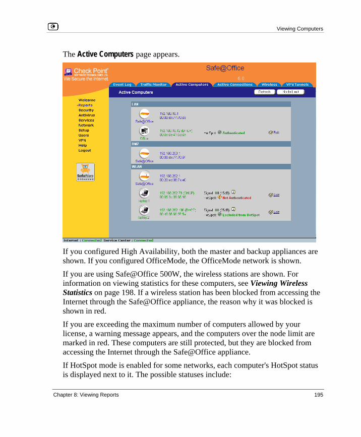
Viewing Computers
Chapter 8: Viewing Reports 195
The Active Computers page appears.
If you configured High Availability, both the master and backup appliances are shown. If you configured OfficeMode, the OfficeMode network is shown.
If you are using Safe@Office 500W, the wireless stations are shown. For information on viewing statistics for these computers, see Viewing Wireless Statistics on page 198. If a wireless station has been blocked from accessing the Internet through the Safe@Office appliance, the reason why it was blocked is shown in red.
If you are exceeding the maximum number of computers allowed by your license, a warning message appears, and the computers over the node limit are marked in red. These computers are still protected, but they are blocked from accessing the Internet through the Safe@Office appliance.
If HotSpot mode is enabled for some networks, each computer's HotSpot status is displayed next to it. The possible statuses include:

Viewing Computers
196 Check Point Safe@Office User Guide
• Authenticated. The computer is logged on to My HotSpot.
• Not Authenticated. The computer is not logged on to My HotSpot.
• Excluded from HotSpot. The computer is in an IP address range excluded from HotSpot enforcement. To enforce HotSpot, you must edit the network object. See Adding and Editing Network Objects on page 130.
Note: Computers that did not communicate through the firewall are not counted for node limit purposes, even though they are protected by the firewall.
Note: To increase the number of computers allowed by your license, you can upgrade your product. For further information, see Upgrading Your Software Product on page 381.
Next to each computer, an Add button enables you to add a network object for the computer, or an Edit button enables you to edit an existing network object for the computer. For information on adding and editing network objects, see Adding and Editing Network Objects on page 130.
2. To refresh the display, click Refresh.
3. To view node limit information, do the following:
a. Click Node Limit. The Node Limit window appears with installed software product and the number of nodes used.
b. Click Close to close the window.

Viewing Connections
Chapter 8: Viewing Reports 197
Viewing Connections
This option allows you to view the currently active connections between your network and the external world.
To view the active connections
1. Click Reports in the main menu, and click the Active Connections tab.
The Active Connections page appears.
The page displays the information in the table below.
2. To refresh the display, click Refresh.
3. To view information on the destination machine, click its IP address.
The Safe@Office appliance queries the Internet WHOIS server, and a window displays the name of the entity to which the IP address is registered and their contact information.

Viewing Wireless Statistics
198 Check Point Safe@Office User Guide
4. To view information about a port, click the port.
A window opens displaying information about the port.
Table 28: Active Connections Fields
This field… Displays…
Protocol The protocol used (TCP, UDP, etc.)
Source - IP Address The source IP address
Source - Port The source port
Destination - IP
Address
The destination IP address
Destination -Port The destination port
QoS Class The QoS class to which the connection belongs
Options An icon indicating further details:
• - The connection is encrypted. • - The connection is being scanned by VStream Antivirus.
Viewing Wireless Statistics
If your WLAN is enabled, you can view wireless statistics for the WLAN or for individual wireless stations.
To view statistics for the WLAN
1. Click Reports in the main menu, and click the Wireless tab.

Viewing Wireless Statistics
Chapter 8: Viewing Reports 199
The Wireless page appears.
The page displays the information in the table below.
2. To refresh the display, click Refresh.
Table 29: WLAN Statistics
This field… Displays…
Wireless
Mode
The operation mode used by the WLAN, followed by the transmission rate in
Mbps
MAC Address The MAC address of the Safe@Office appliance's WLAN interface
Domain The Safe@Office access point's region
Country The country configured for the WLAN
Channel The radio frequency used by the WLAN
Viewing Wireless Statistics
200 Check Point Safe@Office User Guide
This field… Displays…
Security The security mode used by the WLAN
Connected
Stations
The number of wireless stations currently connected to the WLAN
Frames OK The total number of frames that were successfully transmitted and received
Errors The total number of transmitted and received frames for which an error
occurred
Discarded/
Dropped
Frames
The total number of discarded or dropped frames transmitted and received
Unicast Frames The number of unicast frames transmitted and received
Broadcast
Frames
The number of broadcast frames transmitted and received
Multicast
Frames
The number of multicast frames transmitted and received
To view statistics for a wireless station
1. Click Reports in the main menu, and click the Active Computers tab.
The Active Computers page appears.
The following information appears next to each wireless station:
• The signal strength in dB
• A bar chart representing the signal strength 2. Mouse-over the information icon next to the wireless station.
A tooltip displays displays statistics for the wireless station, as described in the table below.

Viewing Wireless Statistics
Chapter 8: Viewing Reports 201
3. To refresh the display, click Refresh.
Table 30: Wireless Station Statistics
This field… Displays…
Current Rate The current reception and transmission rate in Mbps
Frames OK The total number of frames that were successfully transmitted and received
Errors The total number of transmitted and received frames for which an error
occurred
Discarded/
Dropped
Frames
The total number of discarded or dropped frames transmitted and received
Unicast Frames The number of unicast frames transmitted and received
Broadcast
Frames
The number of broadcast frames transmitted and received
Multicast
Frames
The number of multicast frames transmitted and received
WLAN Mode The wireless client's operation mode, indicating the client's maximum speed.
Possible values are B, G, and 108G.
For more information, see Basic WLAN Settings Fields on page 168.
XR Indicates whether the wireless client supports Extended Range (XR) mode.
Possible values are:
• yes. The wireless client supports XR mode. • no. The wireless client does not support XR mode.

Viewing Wireless Statistics
202 Check Point Safe@Office User Guide
This field… Displays…
Cipher The security protocol used for the connection with the wireless client.
For more information, see Wireless Security Protocols on page 163.

Default Security Policy
Chapter 9: Setting Your Security Policy 203
Chapter 9
This chapter describes how to set up your Safe@Office appliance security policy.
You can enhance your security policy by subscribing to services such as Web Filtering and Email Filtering. For information on subscribing to services, see Using Subscription Services on page 281.
This chapter includes the following topics: Default Security Policy.............................................................................203 Setting the Firewall Security Level ..........................................................204 Configuring Servers..................................................................................207 Using Rules ..............................................................................................209 Using SmartDefense.................................................................................220 Using Secure HotSpot ..............................................................................256 Defining an Exposed Host........................................................................261
Default Security Policy The Safe@Office default security policy includes the following rules:
Setting Your Security Policy

Setting the Firewall Security Level
204 Check Point Safe@Office User Guide
• Access is blocked from the WAN (Internet) to all internal networks (LAN, DMZ, WLAN, VLANs, and OfficeMode).
• Access is allowed from the internal networks to the WAN, according to the firewall security level (Low/Medium/High).
• Access is allowed from the LAN network to the other internal networks (DMZ, WLAN, VLANs, and OfficeMode).
• Access is blocked from the DMZ, WLAN, VLAN, and OfficeMode networks to the other internal networks, (including between different VLANs).
• HTTP access to the Safe@Office Portal (my.firewall and my.vpn) is allowed from all internal networks except the WLAN. The WLAN can only access the Safe@Office Portal using HTTPS, unless a specific user-defined rule allows this.
• When using the print server function (see Using Network Printers on page 425), access from internal networks to connected network printers is allowed.
• Access from the WAN to network printers is blocked.
These rules are independent of the firewall security level.
You can easily override the default security policy, by creating user-defined firewall rules. For further information, see Using Rules on page 209.
Setting the Firewall Security Level
The firewall security level can be controlled using a simple lever available on the Firewall page. You can set the lever to three states.
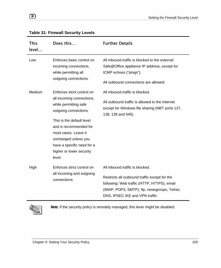
Setting the Firewall Security Level
Chapter 9: Setting Your Security Policy 205
Table 31: Firewall Security Levels
This level…
Does this… Further Details
Low Enforces basic control on
incoming connections,
while permitting all
outgoing connections.
All inbound traffic is blocked to the external
Safe@Office appliance IP address, except for
ICMP echoes ("pings").
All outbound connections are allowed.
Medium Enforces strict control on
all incoming connections,
while permitting safe
outgoing connections.
This is the default level
and is recommended for
most cases. Leave it
unchanged unless you
have a specific need for a
higher or lower security
level.
All inbound traffic is blocked.
All outbound traffic is allowed to the Internet
except for Windows file sharing (NBT ports 137,
138, 139 and 445).
High Enforces strict control on
all incoming and outgoing
connections.
All inbound traffic is blocked.
Restricts all outbound traffic except for the
following: Web traffic (HTTP, HTTPS), email
(IMAP, POP3, SMTP), ftp, newsgroups, Telnet,
DNS, IPSEC IKE and VPN traffic.
Note: If the security policy is remotely managed, this lever might be disabled.

Setting the Firewall Security Level
206 Check Point Safe@Office User Guide
Note: The definitions of firewall security levels provided in this table represent the Safe@Office appliance’s default security policy. Security updates downloaded from a Service Center may alter this policy and change these definitions.
To change the firewall security level
1. Click Security in the main menu, and click the Firewall tab.
The Firewall page appears.
2. Drag the security lever to the desired level.
The Safe@Office appliance security level changes accordingly.

Configuring Servers
Chapter 9: Setting Your Security Policy 207
Configuring Servers
Note: If you do not intend to host any public Internet servers (Web Server, Mail Server etc.) in your network, you can skip this section.
Using the Safe@Office Portal, you can selectively allow incoming network connections into your network. For example, you can set up your own Web server, Mail server or FTP server.
Note: Configuring servers allows you to create simple Allow and Forward rules for common services, and it is equivalent to creating Allow and Forward rules in the Rules page. For information on creating rules, see Using Rules on page 209.
To allow a service to be run on a specific host
1. Click Security in the main menu, and click the Servers tab.
The Servers page appears, displaying a list of services and a host IP address for each allowed service.

Configuring Servers
208 Check Point Safe@Office User Guide
2. Complete the fields using the information in the table below.
3. Click Apply.

Using Rules
Chapter 9: Setting Your Security Policy 209
Using Rules
The Safe@Office appliance checks the protocol used, the ports range, and the destination IP address, when deciding whether to allow or block traffic.
User-defined rules have priority over the default security policy rules and provide you with greater flexibility in defining and customizing your security policy.
For example, if you assign your company’s accounting department to the LAN network and the rest of the company to the DMZ network, then as a result of the default security policy rules, the accounting department will be able to connect to all company computers, while the rest of the employees will not be able to access any sensitive information on the accounting department computers. You can override the default security policy rules, by creating firewall rules that allow specific DMZ computers (such a manager’s computer) to connect to the LAN network and the accounting department.
The Safe@Office appliance processes user-defined rules in the order they appear in the Rules table, so that rule 1 is applied before rule 2, and so on. This enables you to define exceptions to rules, by placing the exceptions higher up in the Rules table.

Using Rules
210 Check Point Safe@Office User Guide
For example, if you want to block all outgoing FTP traffic, except traffic from a specific IP address, you can create a rule blocking all outgoing FTP traffic and move the rule down in the Rules table. Then create a rule allowing FTP traffic from the desired IP address and move this rule to a higher location in the Rules table than the first rule. In the figure below, the general rule is rule number 2, and the exception is rule number 1.
The Safe@Office appliance will process rule 1 first, allowing outgoing FTP traffic from the specified IP address, and only then it will process rule 2, blocking all outgoing FTP traffic.
The following rule types exist:
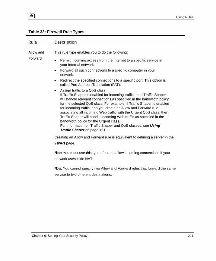
Using Rules
Chapter 9: Setting Your Security Policy 211
Table 33: Firewall Rule Types
Rule Description
Allow and
Forward
This rule type enables you to do the following:
• Permit incoming access from the Internet to a specific service in your internal network.
• Forward all such connections to a specific computer in your network.
• Redirect the specified connections to a specific port. This option is called Port Address Translation (PAT).
• Assign traffic to a QoS class. If Traffic Shaper is enabled for incoming traffic, then Traffic Shaper will handle relevant connections as specified in the bandwidth policy for the selected QoS class. For example, if Traffic Shaper is enabled for incoming traffic, and you create an Allow and Forward rule associating all incoming Web traffic with the Urgent QoS class, then Traffic Shaper will handle incoming Web traffic as specified in the bandwidth policy for the Urgent class. For information on Traffic Shaper and QoS classes, see Using Traffic Shaper on page 151.
Creating an Allow and Forward rule is equivalent to defining a server in the Servers page.
Note: You must use this type of rule to allow incoming connections if your
network uses Hide NAT.
Note: You cannot specify two Allow and Forward rules that forward the same
service to two different destinations.

Using Rules
212 Check Point Safe@Office User Guide
Rule Description
Allow This rule type enables you to do the following:
• Permit outgoing access from your internal network to a specific service on the Internet. Note: You can allow outgoing connections for services that are not permitted by the default security policy.
• Permit incoming access from the Internet to a specific service in your internal network.
• Assign traffic to a QoS class. If Traffic Shaper is enabled for the direction of traffic specified in the rule (incoming or outgoing), then Traffic Shaper will handle relevant connections as specified in the bandwidth policy for the selected QoS class. For example, if Traffic Shaper is enabled for outgoing traffic, and you create an Allow rule associating all outgoing Web traffic with the Urgent QoS class, then Traffic Shaper will handle outgoing Web traffic as specified in the bandwidth policy for the Urgent class. For information on Traffic Shaper and QoS classes, see Using Traffic Shaper on page 151.
Note: You cannot use an Allow rule to permit incoming traffic, if the network or
VPN uses Hide NAT. However, you can use Allow rules for static NAT IP
addresses.
Block This rule type enables you to do the following:
• Block outgoing access from your internal network to a specific service on the Internet.
• Block incoming access from the Internet to a specific service in your internal network.

Using Rules
Chapter 9: Setting Your Security Policy 213
Adding and Editing Rules
To add or edit a rule
1. Click Security in the main menu, and click the Rules tab.
The Rules page appears.
2. Do one of the following:
• To add a new rule, click Add Rule.
• To edit an existing rule, click the Edit icon next to the desired rule.

Using Rules
214 Check Point Safe@Office User Guide
The Safe@Office Firewall Rule wizard opens, with the Step 1: Rule Type dialog box displayed.
3. Select the type of rule you want to create.
4. Click Next. The Step 2: Service dialog box appears.
The example below shows an Allow rule.
5. Complete the fields using the relevant information in the table below.
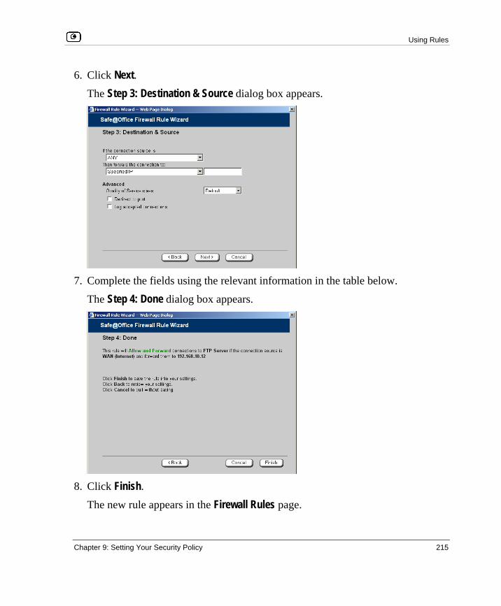
Using Rules
Chapter 9: Setting Your Security Policy 215
6. Click Next. The Step 3: Destination & Source dialog box appears.
7. Complete the fields using the relevant information in the table below.
The Step 4: Done dialog box appears.
8. Click Finish.
The new rule appears in the Firewall Rules page.

Using Rules
216 Check Point Safe@Office User Guide
Table 34: Firewall Rule Fields
In this field… Do this…
Any Service Click this option to specify that the rule should apply to any service.
Standard
Service
Click this option to specify that the rule should apply to a specific standard
service.
You must then select the desired service from the drop-down list.
Custom Service Click this option to specify that the rule should apply to a specific non-
standard service.
The Protocol and Port Range fields are enabled. You must fill them in.
Protocol Select the protocol (ESP, GRE, TCP, UDP or ANY) for which the rule
should apply.
Ports To specify the port range to which the rule applies, type the start port
number in the left text box, and the end port number in the right text box.
Note: If you do not enter a port range, the rule will apply to all ports. If you
enter only one port number, the range will include only that port.
Source Select the source of the connections you want to allow/block.
To specify an IP address, select Specified IP and type the desired IP address
in the filed provided.
To specify an IP address range, select Specified Range and type the desired
IP address range in the fields provided.

Using Rules
Chapter 9: Setting Your Security Policy 217
In this field… Do this…
Destination Select the destination of the connections you want to allow or block.
To specify an IP address, select Specified IP and type the desired IP address
in the text box.
To specify an IP address range, select Specified Range and type the desired
IP address range in the fields provided. This option is not available in Allow
and Forward rules.
To specify the Safe@Office IP address, select This Gateway. This option is
not available in Allow and Forward rules.
To specify any destination except the Safe@Office Portal and network printers, select ANY.
Quality of
Service class
Select the QoS class to which you want to assign the specified connections.
If Traffic Shaper is enabled, Traffic Shaper will handle these connections as
specified in the bandwidth policy for the selected QoS class. If Traffic Shaper
is not enabled, this setting is ignored. For information on Traffic Shaper and
QoS classes, see Using Traffic Shaper on page 151.
This drop-down list only appears when defining an Allow rule or an Allow and
Forward rule.
Log accepted
connections /
Log blocked
connections
Select this option to log the specified blocked or allowed connections.
By default, accepted connections are not logged, and blocked connections
are logged. You can modify this behavior by changing the check box's state.

Using Rules
218 Check Point Safe@Office User Guide
In this field… Do this…
Redirect to port Select this option to redirect the connections to a specific port.
You must then type the desired port in the field provided.
This option is called Port Address Translation (PAT), and is only available
when defining an Allow and Forward rule.
Enabling/Disabling Rules
You can temporarily disable a user-defined rule.
To enable/disable a rule
1. Click Security in the main menu, and click the Rules tab.
The Rules page appears.
2. Next to the desired rule, do one of the following:
• To enable the rule, click .
The button changes to and the rule is enabled.
• To disable the rule, click .
The button changes to and the rule is disabled.

Using Rules
Chapter 9: Setting Your Security Policy 219
Changing Rules' Priority
To change a rule's priority
1. Click Security in the main menu, and click the Rules tab.
The Rules page appears.
2. Do one of the following:
• Click next to the desired rule, to move the rule up in the table.
• Click next to the desired rule, to move the rule down in the table. The rule's priority changes accordingly.
Deleting Rules
To delete an existing rule
1. Click Security in the main menu, and click the Rules tab.
The Rules page appears.
2. Click the Erase icon of the rule you wish to delete.
A confirmation message appears.
3. Click OK.
The rule is deleted.

Using SmartDefense
220 Check Point Safe@Office User Guide
Using SmartDefense
The Safe@Office appliance includes Check Point SmartDefense Services, based on Check Point Application Intelligence. SmartDefense provides a combination of attack safeguards and attack-blocking tools that protect your network in the following ways:
• Validating compliance to standards
• Validating expected usage of protocols (Protocol Anomaly Detection)
• Limiting application ability to carry malicious data
• Controlling application-layer operations
In addition, SmartDefense aids proper usage of Internet resources, such as FTP, instant messaging, Peer-to-Peer (P2P) file sharing, file-sharing operations, and File Transfer Protocol (FTP) uploading, among others.

Using SmartDefense
Chapter 9: Setting Your Security Policy 221
Configuring SmartDefense
For convenience, SmartDefense is organized as a tree, in which each branch represents a category of settings.
When a category is expanded, the settings it contains appear as nodes. For information on each category and the nodes it contains, see SmartDefense Categories on page 224.
Each node represents an attack type, a sanity check, or a protocol or service that is vulnerable to attacks. To control how SmartDefense handles an attack, you must configure the relevant node's settings.

Using SmartDefense
222 Check Point Safe@Office User Guide
To configure a SmartDefense node
1. Click Security in the main menu, and click the SmartDefense tab.
The SmartDefense page appears.
The left pane displays a tree containing SmartDefense categories.
• To expand a category, click the icon next to it.
• To collapse a category, click the icon next to it. 2. Expand the relevant category, and click on the desired node.
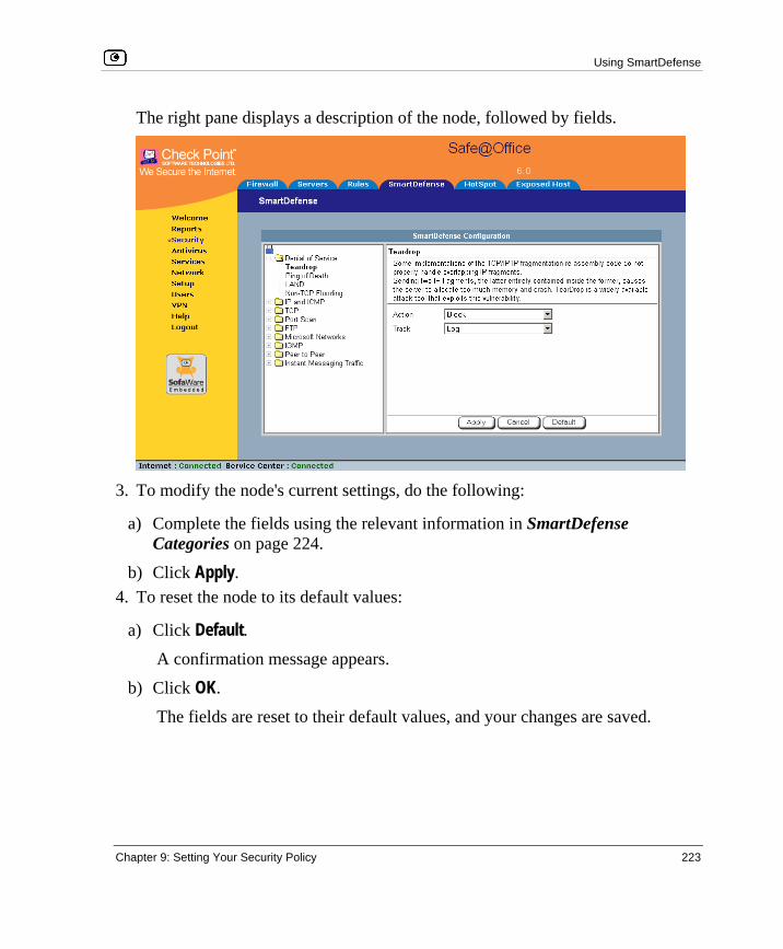
Using SmartDefense
Chapter 9: Setting Your Security Policy 223
The right pane displays a description of the node, followed by fields.
3. To modify the node's current settings, do the following:
a) Complete the fields using the relevant information in SmartDefense Categories on page 224.
b) Click Apply. 4. To reset the node to its default values:
a) Click Default. A confirmation message appears.
b) Click OK.
The fields are reset to their default values, and your changes are saved.

Using SmartDefense
224 Check Point Safe@Office User Guide
SmartDefense Categories SmartDefense includes the following categories:
• Denial of Service on page 224
• IP and ICMP on page 229
• TCP on page 239
• Port Scan on page 242
• FTP on page 245
• Microsoft Networks on page 249
• IGMP on page 251
• Peer to Peer on page 252
• Instant Messengers on page 254
Denial of Service Denial of Service (DoS) attacks are aimed at overwhelming the target with spurious data, to the point where it is no longer able to respond to legitimate service requests.
This category includes the following attacks:
• Teardrop on page 224
• Ping of Death on page 225
• LAND on page 226
• Non-TCP Flooding on page 227
Teardrop In a Teardrop attack, the attacker sends two IP fragments, the latter entirely contained within the former. This causes some computers to allocate too much memory and crash.

Using SmartDefense
Chapter 9: Setting Your Security Policy 225
You can configure how Teardrop attacks should be handled.
Table 35: Teardrop Fields
In this field… Do this…
Action Specify what action to take when a Teardrop attack occurs, by selecting one
of the following:
• Block. Block the attack. This is the default. • None. No action.
Track Specify whether to log Teardrop attacks, by selecting one of the following:
• Log. Log the attack. This is the default. • None. Do not log the attack.
Ping of Death In a Ping of Death attack, the attacker sends a fragmented PING request that exceeds the maximum IP packet size (64KB). Some operating systems are unable to handle such requests and crash.

Using SmartDefense
226 Check Point Safe@Office User Guide
You can configure how Ping of Death attacks should be handled.
Table 36: Ping of Death Fields
In this field… Do this…
Action Specify what action to take when a Ping of Death attack occurs, by selecting
one of the following:
• Block. Block the attack. This is the default. • None. No action.
Track Specify whether to log Ping of Death attacks, by selecting one of the
following:
• Log. Log the attack. This is the default. • None. Do not log the attack.
LAND In a LAND attack, the attacker sends a SYN packet, in which the source address and port are the same as the destination (the victim computer). The victim computer then tries to reply to itself and either reboots or crashes.

Using SmartDefense
Chapter 9: Setting Your Security Policy 227
You can configure how LAND attacks should be handled.
Table 37: LAND Fields
In this field… Do this…
Action Specify what action to take when a LAND attack occurs, by selecting one of
the following:
• Block. Block the attack. This is the default. • None. No action.
Track Specify whether to log LAND attacks, by selecting one of the following:
• Log. Log the attack. This is the default. • None. Do not log the attack.
Non-TCP Flooding Advanced firewalls maintain state information about connections in a State table. In non-TCP Flooding attacks, the attacker sends high volumes of non-TCP traffic. Since such traffic is connectionless, the related state information cannot be cleared or reset, and the firewall State table is quickly filled up. This prevents the firewall from accepting new connections and results in a Denial of Service (DoS).

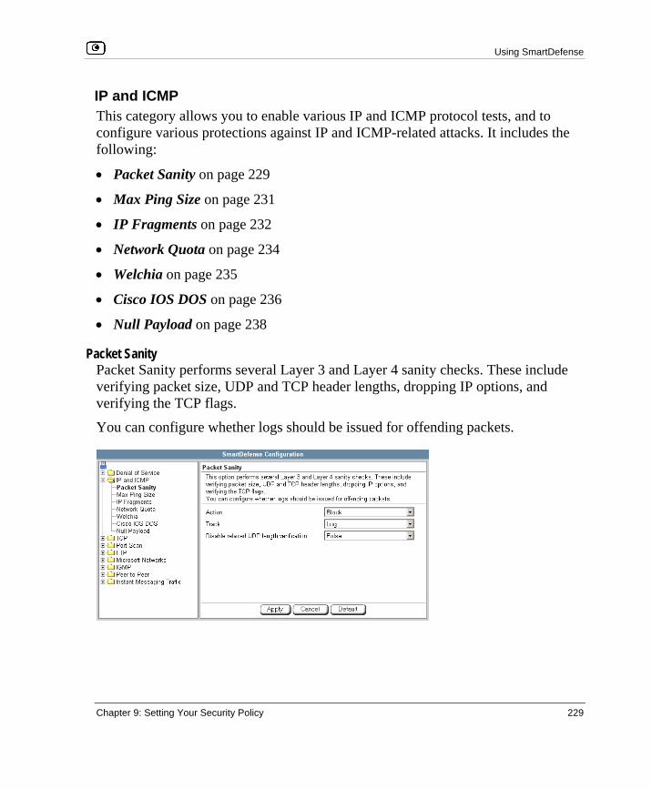
Using SmartDefense
Chapter 9: Setting Your Security Policy 229
IP and ICMP This category allows you to enable various IP and ICMP protocol tests, and to configure various protections against IP and ICMP-related attacks. It includes the following:
• Packet Sanity on page 229
• Max Ping Size on page 231
• IP Fragments on page 232
• Network Quota on page 234
• Welchia on page 235
• Cisco IOS DOS on page 236
• Null Payload on page 238
Packet Sanity Packet Sanity performs several Layer 3 and Layer 4 sanity checks. These include verifying packet size, UDP and TCP header lengths, dropping IP options, and verifying the TCP flags.
You can configure whether logs should be issued for offending packets.

Using SmartDefense
230 Check Point Safe@Office User Guide
Table 39: Packet Sanity Fields
In this field… Do this…
Action Specify what action to take when a packet fails a sanity test, by selecting
one of the following:
• Block. Block the packet. This is the default. • None. No action.
Track Specify whether to issue logs for packets that fail the packet sanity tests, by
selecting one of the following:
• Log. Issue logs. This is the default. • None. Do not issue logs.
Disable relaxed
UDP length
verification
The UDP length verification sanity check measures the UDP header length
and compares it to the UDP header length specified in the UDP header. If
the two values differ, the packet may be corrupted.
However, since different applications may measure UDP header length
differently, the Safe@Office appliance relaxes the UDP length verification
sanity check by default, performing the check but not dropping offending
packets. This is called relaxed UDP length verification.
Specify whether the Safe@Office appliance should relax the UDP length
verification sanity check or not, by selecting one of the following:
• True. Disable relaxed UDP length verification. The Safe@Office appliance will drop packets that fail the UDP length verification check.
• False. Do not disable relaxed UDP length verification. The Safe@Office appliance will not drop packets that fail the UDP length verification check. This is the default.

Using SmartDefense
Chapter 9: Setting Your Security Policy 231
Max Ping Size PING (ICMP echo request) is a program that uses ICMP protocol to check whether a remote machine is up. A request is sent by the client, and the server responds with a reply echoing the client's data.
An attacker can echo the client with a large amount of data, causing a buffer overflow. You can protect against such attacks by limiting the allowed size for ICMP echo requests.
Table 40: Max Ping Size Fields
In this field… Do this…
Action Specify what action to take when an ICMP echo response exceeds the Max Ping Size threshold, by selecting one of the following:
• Block. Block the request. This is the default. • None. No action.
Track Specify whether to log ICMP echo responses that exceed the Max Ping Size
threshold, by selecting one of the following:
• Log. Log the responses. This is the default. • None. Do not log the responses.

Using SmartDefense
232 Check Point Safe@Office User Guide
In this field… Do this…
Max Ping Size Specify the maximum data size for ICMP echo response.
The default value is 1500.
IP Fragments When an IP packet is too big to be transported by a network link, it is split into several smaller IP packets and transmitted in fragments. To conceal a known attack or exploit, an attacker might imitate this common behavior and break the data section of a single packet into several fragmented packets. Without reassembling the fragments, it is not always possible to detect such an attack. Therefore, the Safe@Office appliance always reassembles all the fragments of a given IP packet, before inspecting it to make sure there are no attacks or exploits in the packet.
You can configure how fragmented packets should be handled.

Using SmartDefense
Chapter 9: Setting Your Security Policy 233
Table 41: IP Fragments Fields
In this field… Do this…
Forbid IP Fragments Specify whether all fragmented packets should be dropped, by selecting
one of the following:
• True. Drop all fragmented packets. • False. No action. This is the default.
Under normal circumstances, it is recommended to leave this field set to False. Setting this field to True may disrupt Internet connectivity, because
it does not allow any fragmented packets.
Max Number of
Incomplete Packets
Type the maximum number of fragmented packets allowed. Packets
exceeding this threshold will be dropped.
The default value is 300.
Timeout for
Discarding
Incomplete Packets
When the Safe@Office appliance receives packet fragments, it waits for
additional fragments to arrive, so that it can reassemble the packet.
Type the number of seconds to wait before discarding incomplete
packets.
The default value is 10.
Track Specify whether to log fragmented packets, by selecting one of the
following:
• Log. Log all fragmented packets. • None. Do not log the fragmented packets. This is the default.

Using SmartDefense
234 Check Point Safe@Office User Guide
Network Quota An attacker may try to overload a server in your network by establishing a very large number of connections per second. To protect against Denial Of Service (DoS) attacks, Network Quota enforces a limit upon the number of connections per second that are allowed from the same source IP address.
You can configure how connection that exceed that limit should be handled.
Table 42: Network Quota Fields
In this field… Do this…
Action Specify what action to take when the number of network connections from the same source reaches the Max. Connections/Second per Source IP
threshold. Select one of the following:
• Block. Block all new connections from the source. Existing connections will not be blocked. This is the default.
• None. No action.
Track Specify whether to log connections from a specific source that exceed the Max. Connections/Second per Source IP threshold, by selecting one of
the following:
• Log. Log the connections. This is the default. • None. Do not log the connections.

Using SmartDefense
Chapter 9: Setting Your Security Policy 235
In this field… Do this…
Max.
Connections/Second
from Same Source IP
Type the maximum number of network connections allowed per second
from the same source IP address.
The default value is 100.
Set a lower threshold for stronger protection against DoS attacks.
Note: Setting this value too low can lead to false alarms.
Welchia The Welchia worm uses the MS DCOM vulnerability or a WebDAV vulnerability. After infecting a computer, the worm begins searching for other live computers to infect. It does so by sending a specific ping packet to a target and waiting for the reply that signals that the target is alive. This flood of pings may disrupt network connectivity.
You can configure how the Welchia worm should be handled.

Using SmartDefense
236 Check Point Safe@Office User Guide
Table 43: Welchia Fields
In this field… Do this…
Action Specify what action to take when the Welchia worm is detected, by selecting
one of the following:
• Block. Block the attack. This is the default. • None. No action.
Track Specify whether to log Welchia worm attacks, by selecting one of the
following:
• Log. Log the attack. This is the default. • None. Do not log the attack.
Cisco IOS DOS Cisco routers are configured to process and accept Internet Protocol version 4 (IPv4) packets by default. When a Cisco IOS device is sent a specially crafted sequence of IPv4 packets (with protocol type 53 - SWIPE, 55 - IP Mobility, 77 - Sun ND, or 103 - Protocol Independent Multicast - PIM), the router will stop processing inbound traffic on that interface.

Using SmartDefense
Chapter 9: Setting Your Security Policy 237
You can configure how Cisco IOS DOS attacks should be handled.
Table 44: Cisco IOS DOS
In this field… Do this…
Action Specify what action to take when a Cisco IOS DOS attack occurs,
by selecting one of the following:
• Block. Block the attack. This is the default. • None. No action.
Track Specify whether to log Cisco IOS DOS attacks, by selecting one of
the following:
• Log. Log the attack. This is the default. • None. Do not log the attack.
Number of Hops to Protect Type the number of hops from the enforcement module that Cisco
routers should be protected.
The default value is 10.


Using SmartDefense
Chapter 9: Setting Your Security Policy 239
In this field… Do this…
Track Specify whether to log null payload ping packets, by selecting one of the
following:
• Log. Log the packets. This is the default. • None. Do not log the packets.
TCP This category allows you to configure various protections related to the TCP protocol. It includes the following:
• Strict TCP on page 239
• Small PMTU on page 241
Strict TCP Out-of-state TCP packets are SYN-ACK or data packets that arrive out of order, before the TCP SYN packet.
Note: In normal conditions, out-of-state TCP packets can occur after the Safe@Office restarts, since connections which were established prior to the reboot are unknown. This is normal and does not indicate an attack.

Using SmartDefense
240 Check Point Safe@Office User Guide
You can configure how out-of-state TCP packets should be handled.
Table 46: Strict TCP
In this field… Do this…
Action Specify what action to take when an out-of-state TCP packet arrives, by
selecting one of the following:
• Block. Block the packets. • None. No action. This is the default.
Track Specify whether to log null payload ping packets, by selecting one of the
following:
• Log. Log the packets. This is the default. • None. Do not log the packets.

Using SmartDefense
Chapter 9: Setting Your Security Policy 241
Small PMTU Small PMTU (Packet MTU) is a bandwidth attack in which the client fools the server into sending large amounts of data using small packets. Each packet has a large overhead that creates a "bottleneck" on the server.
You can protect against this attack by specifying a minimum packet size for data sent over the Internet.
Table 47: Small PMTU Fields
In this field… Do this…
Action Specify what action to take when a packet is smaller than the Minimal MTU Size threshold, by selecting one of the following:
• Block. Block the packet. • None. No action. This is the default.
Track Specify whether to issue logs for packets are smaller than the Minimal MTU Size threshold, by selecting one of the following:
• Log. Issue logs. This is the default. • None. Do not issue logs.

Using SmartDefense
242 Check Point Safe@Office User Guide
In this field… Do this…
Minimal MTU
Size
Type the minimum value allowed for the MTU field in IP packets sent by a
client.
An overly small value will not prevent an attack, while an overly large value
might degrade performance and cause legitimate requests to be dropped.
The default value is 300.
Port Scan An attacker can perform a port scan to determine whether ports are open and vulnerable to an attack. This is most commonly done by attempting to access a port and waiting for a response. The response indicates whether or not the port is open.
This category includes the following types of port scans:
• Host Port Scan. The attacker scans a specific host's ports to determine which of the ports are open.
• Sweep Scan. The attacker scans various hosts to determine where a specific port is open.
You can configure how the Safe@Office appliance should react when a port scan is detected.

Using SmartDefense
Chapter 9: Setting Your Security Policy 243
Table 48: Port Scan Fields
In this field… Do this…
Number of ports
accessed
SmartDefense detects ports scans by measuring the number of ports
accessed over a period of time. The number of ports accessed must exceed the Number of ports accessed value, within the number of seconds specified by
the In a period of [seconds] value, in order for SmartDefense to consider the
activity a scan.
Type the minimum number of ports that must be accessed within the In a period of [seconds] period, in order for SmartDefense to detect the activity as
a port scan.
For example, if this value is 30, and 40 ports are accessed within a specified
period of time, SmartDefense will detect the activity as a port scan.
For Host Port Scan, the default value is 30. For Sweep Scan, the default
value is 50.

Using SmartDefense
244 Check Point Safe@Office User Guide
In this field… Do this…
In a period of
[seconds]
SmartDefense detects ports scans by measuring the number of ports
accessed over a period of time. The number of ports accessed must exceed the Number of ports accessed value, within the number of seconds specified by
the In a period of [seconds] value, in order for SmartDefense to consider the
activity a scan.
Type the maximum number of seconds that can elapse, during which the Number of ports accessed threshold is exceeded, in order for SmartDefense to
detect the activity as a port scan.
For example, if this value is 20, and the Number of ports accessed threshold is
exceeded for 15 seconds, SmartDefense will detect the activity as a port
scan. If the threshold is exceeded for 30 seconds, SmartDefense will not
detect the activity as a port scan.
The default value is 20 seconds.
Track Specify whether to issue logs for scans, by selecting one of the following:
• Log. Issue logs. This is the default. • None. Do not issue logs. This is the default.
Detect scans
from Internet only
Specify whether to detect only scans originating from the Internet, by
selecting one of the following:
• False. Do not detect only scans from the Internet. This is the default.
• True. Detect only scans from the Internet.

Using SmartDefense
Chapter 9: Setting Your Security Policy 245
FTP This category allows you to configure various protections related to the FTP protocol. It includes the following:
• FTP Bounce on page 245
• Block Known Ports on page 246
• Block Port Overflow on page 247
• Blocked FTP Commands on page 248
FTP Bounce When connecting to an FTP server, the client sends a PORT command specifying the IP address and port to which the FTP server should connect and send data. An FTP Bounce attack is when an attacker sends a PORT command specifying the IP address of a third party instead of the attacker's own IP address. The FTP server then sends data to the victim machine.
You can configure how FTP bounce attacks should be handled.

Using SmartDefense
246 Check Point Safe@Office User Guide
Table 49: FTP Bounce Fields
In this field… Do this…
Action Specify what action to take when an FTP Bounce attack occurs, by selecting
one of the following:
• Block. Block the attack. This is the default. • None. No action.
Track Specify whether to log FTP Bounce attacks, by selecting one of the
following:
• Log. Log the attack. This is the default. • None. Do not log the attack.
Block Known Ports You can choose to block the FTP server from connecting to well-known ports.
Note: Known ports are published ports associated with services (for example, SMTP is port 25).
This provides a second layer of protection against FTP bounce attacks, by preventing such attacks from reaching well-known ports.


Using SmartDefense
248 Check Point Safe@Office User Guide
Table 51: Block Port Overflow
In this field… Do this…
Action Specify what action to take for PORT commands containing a number
greater than 255, by selecting one of the following:
• Block. Block the PORT command. This is the default. • None. No action.
Blocked FTP Commands Some seldom-used FTP commands may compromise FTP server security and integrity. You can specify which FTP commands should be allowed to pass through the security server, and which should be blocked.
To enable FTP command blocking
• In the Action drop-down list, select Block.
The FTP commands listed in the Blocked commands box will be blocked.
FTP command blocking is enabled by default.

Using SmartDefense
Chapter 9: Setting Your Security Policy 249
To disable FTP command blocking
• In the Action drop-down list, select None.
All FTP commands are allowed, including those in the Blocked commands box.
To block a specific FTP command
1. In the Allowed commands box, select the desired FTP command.
2. Click Block.
The FTP command appears in the Blocked commands box.
3. Click Apply.
When FTP command blocking is enabled, the FTP command will be blocked.
To allow a specific FTP command
1. In the Blocked commands box, select the desired FTP command.
2. Click Accept. The FTP command appears in the Allowed commands box.
3. Click Apply.
The FTP command will be allowed, regardless of whether FTP command blocking is enabled or disabled.
Microsoft Networks This category includes File and Print Sharing.
Microsoft operating systems and Samba clients rely on Common Internet File System (CIFS), a protocol for sharing files and printers. However, this protocol is also widely used by worms as a means of propagation.

Using SmartDefense
250 Check Point Safe@Office User Guide
You can configure how CIFS worms should be handled.
Table 52: File Print and Sharing Fields
In this field… Do this…
Action Specify what action to take when a CIFS worm attack is detected, by
selecting one of the following:
• Block. Block the attack. • None. No action. This is the default.
Track Specify whether to log CIFS worm attacks, by selecting one of the
following:
• Log. Log the attack. • None. Do not log the attack. This is the default.
CIFS worm patterns
list
Select the worm patterns to detect.
Patterns are matched against file names (including file paths but excluding the disk share name) that the client is trying to read or write from the server.

Using SmartDefense
Chapter 9: Setting Your Security Policy 251
IGMP This category includes the IGMP protocol.
IGMP is used by hosts and routers to dynamically register and discover multicast group membership. Attacks on the IGMP protocol usually target a vulnerability in the multicast routing software/hardware used, by sending specially crafted IGMP packets.
You can configure how IGMP attacks should be handled.
Table 53: IGMP Fields
In this field… Do this…
Action Specify what action to take when an IGMP attack occurs, by selecting
one of the following:
• Block. Block the attack. This is the default. • None. No action.
Track Specify whether to log IGMP attacks, by selecting one of the following:
• Log. Log the attack. This is the default. • None. Do not log the attack.

Using SmartDefense
252 Check Point Safe@Office User Guide
In this field… Do this…
Enforce IGMP to
multicast addresses
According to the IGMP specification, IGMP packets must be sent to
multicast addresses. Sending IGMP packets to a unicast or broadcast
address might constitute and attack; therefore the Safe@Office appliance
blocks such packets.
Specify whether to allow or block IGMP packets that are sent to non-
multicast addresses, by selecting one of the following:
• Block. Block IGMP packets that are sent to non-multicast addresses. This is the default.
• None. No action.
Peer to Peer SmartDefense can block peer-to-peer traffic, by identifying the proprietary protocols and preventing the initial connection to the peer-to-peer networks. This prevents not only downloads, but also search operations.
This category includes the following nodes:
• KaZaA
• Gnutella
• eMule
• BitTorrent
Note: SmartDefense can detect peer-to-peer traffic regardless of the TCP port being used to initiate the session.

Using SmartDefense
Chapter 9: Setting Your Security Policy 253
In each node, you can configure how peer-to-peer connections of the selected type should be handled, using the table below.
Table 54: Peer to Peer Fields
In this field… Do this…
Action Specify what action to take when a connection is attempted, by selecting
one of the following:
• Block. Block the connection. • None. No action. This is the default.
Track Specify whether to log peer-to-peer connections, by selecting one of the
following:
• Log. Log the connection. • None. Do not log the connection. This is the default.
Block proprietary
protocols on all ports
Specify whether proprietary protocols should be blocked on all ports, by
selecting one of the following:
• Block. Block the proprietary protocol on all ports. This in effect prevents all communication using this peer-to-peer application. This is the default.
• None. Do not block the proprietary protocol on all ports.

Using SmartDefense
254 Check Point Safe@Office User Guide
Instant Messengers SmartDefense can block instant messaging applications that use VoIP protocols, by identifying the messaging application's fingerprints and HTTP headers.
This category includes the following nodes:
• Skype
• Yahoo
• ICQ
Note: SmartDefense can detect instant messaging traffic regardless of the TCP port being used to initiate the session.
In each node, you can configure how instant messaging connections of the selected type should be handled, using the table below.

Using SmartDefense
Chapter 9: Setting Your Security Policy 255
Table 55: Instant Messengers Fields
In this field… Do this…
Action Specify what action to take when a connection is attempted, by selecting
one of the following:
• Block. Block the connection. • None. No action. This is the default.
Track Specify whether to log instant messenger connections, by selecting one
of the following:
• Log. Log the connection. • None. Do not log the connection. This is the default.
Block proprietary
protocols on all ports
Specify whether proprietary protocols should be blocked on all ports, by
selecting one of the following:
• Block. Block the proprietary protocol on all ports. This in effect prevents all communication using this instant messenger application. This is the default.
• None. Do not block the proprietary protocol on all ports.

Using Secure HotSpot
256 Check Point Safe@Office User Guide
Using Secure HotSpot
You can enable your Safe@Office appliance as a public Internet access hotspot for specific networks. When users on those networks attempt to access the Internet, they are automatically re-directed to the My HotSpot page http://my.hotspot. On this page, they must read and accept the My HotSpot terms of use, and if My HotSpot is configured to be password-protected, they must log on using their Safe@Office username and password. The users may then access the Internet.
Users can also log out in the My HotSpot page.
Note: HotSpot users are automatically logged out after one hour of inactivity.
Safe@Office Secure HotSpot is useful in any wired or wireless environment where Web-based user authentication or terms-of-use approval is required prior to gaining access to the network. For example, Secure HotSpot can be used in public computer labs, educational institutions, libraries, Internet cafés, and so on.
The Safe@Office appliance allows you to add guest users quickly and easily. By default, guest users are given a username and password that expire in 24 hours and granted HotSpot Access permissions only. For information on adding quick guest users, see Adding Quick Guest Users on page 367.

Using Secure HotSpot
Chapter 9: Setting Your Security Policy 257
You can choose to exclude specific network objects from HotSpot enforcement. For information, see Using Network Objects on page 129.
Important: SecuRemote VPN software users who are authenticated by the Internal VPN Server are automatically exempt from HotSpot enforcement. This allows, for example, authenticated employees to gain full access to the corporate LAN, while guest users are permitted to access the Internet only.
Note: HotSpot enforcement can block traffic passing through the firewall; however, it does not block local traffic on the same network segment (traffic that does not pass through the firewall).
Setting Up Secure HotSpot
To set up Secure HotSpot
1. Enable Secure HotSpot for the desired networks.
See Enabling/Disabling Secure HotSpot on page 258.
2. Customize Secure HotSpot as desired.
See Customizing Secure HotSpot on page 259.
3. Grant HotSpot Access permissions to users on the selected networks.
See Adding and Editing Users on page 363.
4. To exclude specific computers from HotSpot enforcement, by adding or editing their network objects.
See Adding and Editing Network Objects on page 130.
You must select Exclude this computer/network from HotSpot enforcement option.
5. Add quick guest users as needed.
See Adding Quick Guest Users on page 367.

Using Secure HotSpot
258 Check Point Safe@Office User Guide
Enabling/Disabling Secure HotSpot
To enable/disable Secure HotSpot
1. Click Security in the main menu, and click the My HotSpot tab.
The My HotSpot page appears.
2. In the HotSpot Networks area, do one of the following:
• To enable Secure HotSpot for a specific network, select the check box next to the network.
• To disable Secure HotSpot for a specific network, clear the check box next to the network.
3. Click Apply.

Using Secure HotSpot
Chapter 9: Setting Your Security Policy 259
Customizing Secure HotSpot
To customize Secure HotSpot
1. Click Security in the main menu, and click the My HotSpot tab.
The My HotSpot page appears.
2. Complete the fields using the information in the table below.
Additional fields may appear.
3. To preview the My HotSpot page, click Preview.
A browser window opens displaying the My HotSpot page.

Using Secure HotSpot
260 Check Point Safe@Office User Guide
4. Click Apply.
Your changes are saved.
Table 56: My HotSpot Fields
In this field… Do this…
My HotSpot
Title
Type the title that should appear on the My HotSpot page.
The default title is "Welcome to My HotSpot".
My HotSpot
Terms
Type the terms to which the user must agree before accessing the Internet.
You can use HTML tags as needed.
My HotSpot is
password
protected
Select this option to require users to enter their username and password
before accessing the Internet.
If this option is not selected, users will be required only to accept the terms of
use before accessing the network.
The Allow a user to login from more than one computer at the same time check box
appears.
Allow a user to
login from more
than one
computer at the
same time
Select this option to allow a single user to log on to My HotSpot from multiple
computers at the same time.

Defining an Exposed Host
Chapter 9: Setting Your Security Policy 261
Defining an Exposed Host
The Safe@Office appliance allows you to define an exposed host, which is a computer that is not protected by the firewall. This is useful for setting up a public server. It allows unlimited incoming and outgoing connections between the Internet and the exposed host computer.
The exposed host receives all traffic that was not forwarded to another computer by use of Allow and Forward rules.
Warning: Entering an IP address may make the designated computer vulnerable to hacker attacks. Defining an exposed host is not recommended unless you are fully aware of the security risks.
To define a computer as an exposed host
1. Click Security in the main menu, and click the Exposed Host tab.
The Exposed Host page appears.

Defining an Exposed Host
262 Check Point Safe@Office User Guide
2. In the Exposed Host field, type the IP address of the computer you wish to define as an exposed host.
Alternatively, you can click This Computer to define your computer as the exposed host.
3. Click Apply.
The selected computer is now defined as an exposed host.
To clear the exposed host
1. Click Security in the main menu, and click the Exposed Host tab.
The Exposed Host page appears.
2. Click Clear. 3. Click Apply.
No exposed host is defined.

Overview
Chapter 10: Using VStream Antivirus 263
Chapter 10
This chapter explains how to use the VStream Antivirus engine to block security threats before they reach your network.
This chapter includes the following topics: Overview ..................................................................................................263 Enabling/Disabling VStream Antivirus....................................................265 Viewing VStream Signature Database Information .................................266 Configuring VStream Antivirus ...............................................................267 Updating VStream Antivirus ....................................................................279
Overview The Safe@Office appliance includes VStream Antivirus, an embedded stream-based antivirus engine based on Check Point Stateful Inspection and Application Intelligence technologies, that performs virus scanning at the kernel level.
VStream Antivirus scans files for malicious content on the fly, without downloading the files into intermediate storage. This means minimal added latency and support for unlimited file sizes; and since VStream Antivirus stores only minimal state information per connection, it can scan thousands of connections concurrently. In order to scan archive files on the fly, VStream Antivirus performs real-time decompression and scanning of ZIP, TAR, and GZ archive files, with support for nested archive files.
When VStream Antivirus detects malicious content, the action it takes depends on the protocol in which the virus was found. See the table below. In each case, VStream Antivirus blocks the file and writes a log to the Event Log.
Using VStream Antivirus
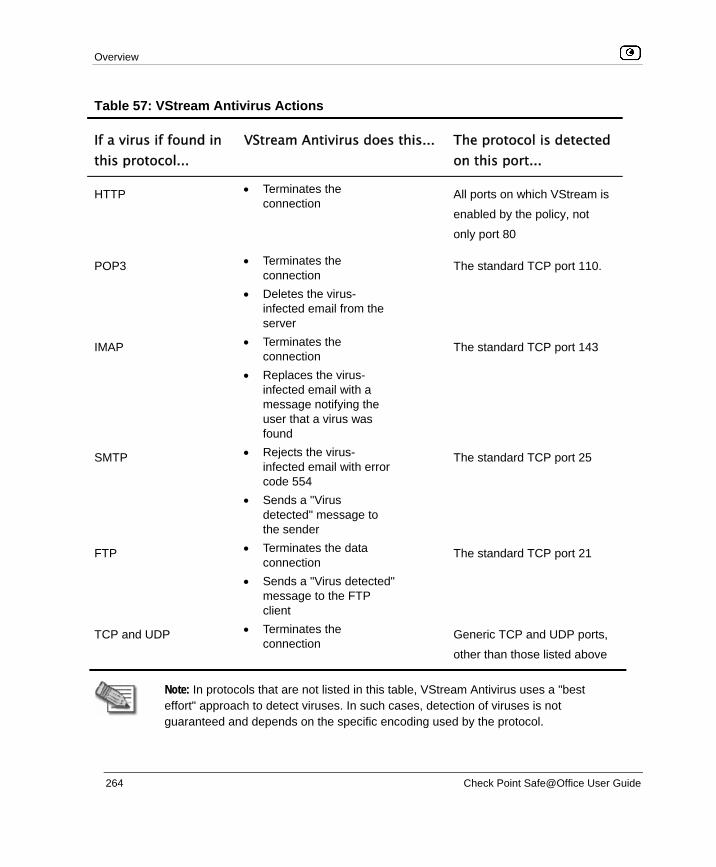
Overview
264 Check Point Safe@Office User Guide
Table 57: VStream Antivirus Actions
If a virus if found in this protocol...
VStream Antivirus does this... The protocol is detected on this port...
HTTP • Terminates the connection
All ports on which VStream is
enabled by the policy, not
only port 80
POP3 • Terminates the connection
• Deletes the virus-infected email from the server
The standard TCP port 110.
IMAP • Terminates the connection
• Replaces the virus-infected email with a message notifying the user that a virus was found
The standard TCP port 143
SMTP • Rejects the virus-infected email with error code 554
• Sends a "Virus detected" message to the sender
The standard TCP port 25
FTP • Terminates the data connection
• Sends a "Virus detected" message to the FTP client
The standard TCP port 21
TCP and UDP • Terminates the connection
Generic TCP and UDP ports,
other than those listed above
Note: In protocols that are not listed in this table, VStream Antivirus uses a "best effort" approach to detect viruses. In such cases, detection of viruses is not guaranteed and depends on the specific encoding used by the protocol.

Enabling/Disabling VStream Antivirus
Chapter 10: Using VStream Antivirus 265
If you are subscribed to the VStream Antivirus subscription service, VStream Antivirus virus signatures are automatically updated, so that security is always up-to-date, and your network is always protected.
Note: VStream Antivirus differs from the Email Antivirus subscription service (part of the Email Filtering service) in the following ways:
• Email Antivirus is centralized, redirecting traffic through the Service Center for scanning, while VStream Antivirus scans for viruses in the Safe@Office gateway itself.
• Email Antivirus is specific to email, scanning incoming POP3 and outgoing SMTP connections only, while VStream Antivirus supports additional protocols, including incoming SMTP and outgoing POP3 connections.
You can use either antivirus solution or both in conjunction. For information on Email Antivirus, see Email Filtering on page 294.
Enabling/Disabling VStream Antivirus
To enable/disable VStream Antivirus
1. Click Antivirus in the main menu, and click the Antivirus tab.

Viewing VStream Signature Database Information
266 Check Point Safe@Office User Guide
The VStream Antivirus page appears.
2. Drag the On/Off lever upwards or downwards.
VStream Antivirus is enabled/disabled for all internal network computers.
Viewing VStream Signature Database Information
VStream Antivirus maintains two databases: a daily database and a main database. The daily database is updated frequently with the newest virus signatures. Periodically, the contents of the daily database are moved to the main database, leaving the daily database empty. This system of incremental updates to the main database allows for quicker updates and saves on network bandwidth.
You can view information about the VStream signature databases currently in use, in the VStream Antivirus page.

Configuring VStream Antivirus
Chapter 10: Using VStream Antivirus 267
Table 58: Account Page Fields
This field… Displays…
Main database The date and time at which the main database was last updated,
followed by the version number.
Daily database The date and time at which the daily database was last updated, followed
by the version number.
Next update The next date and time at which the Safe@Office appliance will check for
updates.
Status The current status of the database. This includes the following statuses:
• Database Not Installed • OK
Configuring VStream Antivirus You can configure VStream Antivirus in the following ways:
• Configuring the VStream Antivirus Policy on page 267
• Configuring VStream Advanced Settings on page 275
Configuring the VStream Antivirus Policy
VStream Antivirus includes a flexible mechanism that allows the user to define exactly which traffic should be scanned, by specifying the protocol, ports, and source and destination IP addresses.
VStream Antivirus processes policy rules in the order they appear in the Antivirus Policy table, so that rule 1 is applied before rule 2, and so on. This enables you to define exceptions to rules, by placing the exceptions higher up in the Rules table.
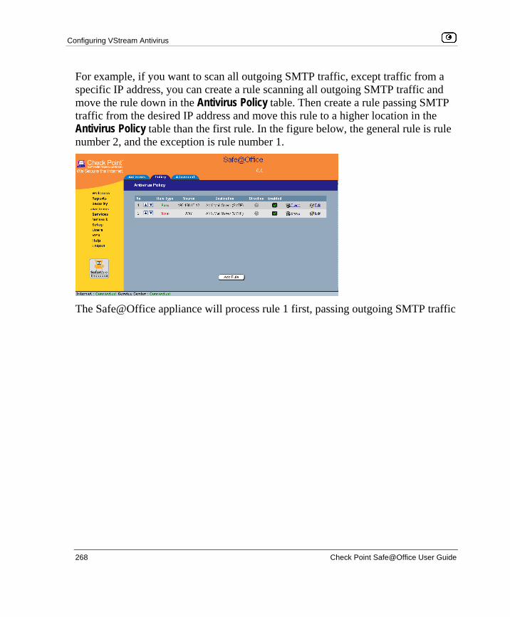
Configuring VStream Antivirus
268 Check Point Safe@Office User Guide
For example, if you want to scan all outgoing SMTP traffic, except traffic from a specific IP address, you can create a rule scanning all outgoing SMTP traffic and move the rule down in the Antivirus Policy table. Then create a rule passing SMTP traffic from the desired IP address and move this rule to a higher location in the Antivirus Policy table than the first rule. In the figure below, the general rule is rule number 2, and the exception is rule number 1.
The Safe@Office appliance will process rule 1 first, passing outgoing SMTP traffic

Configuring VStream Antivirus
Chapter 10: Using VStream Antivirus 269
Rule Description
Scan This rule type enables you to specify that VStream Antivirus should scan traffic
matching the rule.
If a virus is found, it is blocked and logged.
Adding and Editing Rules
To add or edit a rule
1. Click Antivirus in the main menu, and click the Policy tab.
The Antivirus Policy page appears.
2. Do one of the following:
• To add a new rule, click Add Rule.
• To edit an existing rule, click the Edit icon next to the desired rule.

Configuring VStream Antivirus
270 Check Point Safe@Office User Guide
The VStream Policy Rule Wizard opens, with the Step 1: Rule Type dialog box displayed.
3. Select the type of rule you want to create.
4. Click Next. The Step 2: Service dialog box appears.
The example below shows a Scan rule.
5. Complete the fields using the relevant information in the table below.

Configuring VStream Antivirus
Chapter 10: Using VStream Antivirus 271
6. Click Next. The Step 3: Destination & Source dialog box appears.
7. Complete the fields using the relevant information in the table below.
The Step 4: Done dialog box appears.
8. Click Finish.
The new rule appears in the Firewall Rules page.

Configuring VStream Antivirus
272 Check Point Safe@Office User Guide
Table 60: VStream Rule Fields
In this field… Do this…
Any Service Click this option to specify that the rule should apply to any service.
Standard
Service
Click this option to specify that the rule should apply to a specific standard
service.
You must then select the desired service from the drop-down list.
Custom Service Click this option to specify that the rule should apply to a specific non-
standard service.
The Protocol and Port Range fields are enabled. You must fill them in.
Protocol Select the protocol (TCP, UDP, or ANY) for which the rule should apply.
Ports To specify the port range to which the rule applies, type the start port
number in the left text box, and the end port number in the right text box.
Note: If you do not enter a port range, the rule will apply to all ports. If you
enter only one port number, the range will include only that port.
If the
connection
source is
Select the source of the connections you want to allow/block.
To specify an IP address, select Specified IP and type the desired IP address
in the filed provided.
To specify an IP address range, select Specified Range and type the desired
IP address range in the fields provided.

Configuring VStream Antivirus
Chapter 10: Using VStream Antivirus 273
In this field… Do this…
And the
destination is
Select the destination of the connections you want to allow or block.
To specify an IP address, select Specified IP and type the desired IP address
in the text box.
To specify an IP address range, select Specified Range and type the desired
IP address range in the fields provided. This option is not available in Allow
and Forward rules.
To specify the Safe@Office Portal and network printers, select This Gateway.
This option is not available in Allow and Forward rules.
To specify any destination except the Safe@Office Portal and network printers, select ANY.
Data Direction Select the direction of connections to which the rule should apply:
• Download and Upload data. The rule applies to downloaded and uploaded data. This is the default.
• Download data. The rule applies to downloaded data, that is, data flowing from the destination of the connection to the source of the connection.
• Upload data. The rule applies to uploaded data, that is, data flowing from the source of the connection to the destination of the connection.
Enabling/Disabling Rules
You can temporarily disable a VStream Antivirus rule.
To enable/disable a rule
1. Click Antivirus in the main menu, and click the Policy tab.
The Antivirus Policy page appears.

Configuring VStream Antivirus
274 Check Point Safe@Office User Guide
2. Next to the desired rule, do one of the following:
• To enable the rule, click .
The button changes to and the rule is enabled.
• To disable the rule, click .
The button changes to and the rule is disabled.
Changing Rules' Priority
To change a rule's priority
1. Click Antivirus in the main menu, and click the Policy tab.
The Antivirus Policy page appears.
2. Do one of the following:
• Click next to the desired rule, to move the rule up in the table.
• Click next to the desired rule, to move the rule down in the table. The rule's priority changes accordingly.
Deleting Rules
To delete an existing rule
1. Click Antivirus in the main menu, and click the Policy tab.
The Antivirus Policy page appears.
2. Click the Erase icon of the rule you wish to delete.
A confirmation message appears.

Configuring VStream Antivirus
Chapter 10: Using VStream Antivirus 275
3. Click OK.
The rule is deleted.
Configuring VStream Advanced Settings
To configure VStream Antivirus advanced settings
1. Click Antivirus in the main menu, and click the Advanced tab.
The Advanced Antivirus Settings page appears.
2. Complete the fields using the table below.
3. Click Apply.
4. To restore the default VStream Antivirus settings, do the following:
a) Click Default. A confirmation message appears.
b) Click OK.

Configuring VStream Antivirus
276 Check Point Safe@Office User Guide
The VStream Antivirus settings are reset to their defaults. For information on the default values, refer to the table below.
Table 61: Advanced Antivirus Settings Fields
In this field… Do this…
File Types
Block potentially unsafe
file types in email
messages
Select this option to block all emails containing potentially unsafe
attachments.
Unsafe file types are:
• DOS/Windows executables, libraries and drivers • Compiled HTML Help files • VBScript files • Files with {CLSID} in their name • The following file extensions: ade, adp, bas, bat, chm,
cmd,com, cpl, crt, exe, hlp, hta, inf, ins, isp, js, jse, lnk, mdb, mde, msc, msi, msp, mst, pcd, pif, reg, scr, sct, shs,shb, url, vb, vbe, vbs, wsc, wsf, wsh.

Configuring VStream Antivirus
Chapter 10: Using VStream Antivirus 277
In this field… Do this…
Pass safe file types
without scanning
Select this option to accept common file types that are known to
be safe, without scanning them.
Safe files types are:
• MPEG streams • RIFF Ogg Stream • MP3 • PDF • PostScript • WMA/WMV/ASF • RealMedia • JPEG - only the header is scanned, and the rest of
the file is skipped
Selecting this option reduces the load on the gateway by skipping
safe file types. This option is selected by default.
Status
Maximum nesting level Type the maximum number of nested content levels that
VStream Antivirus should scan.
Setting a higher number increases security. Setting a lower
number prevents attackers from overloading the gateway by
sending extremely nested archive files.
The default value is 5 levels.

Configuring VStream Antivirus
278 Check Point Safe@Office User Guide
In this field… Do this…
Maximum compression
ratio 1:x
Fill in the field to complete the maximum compression ratio of
files that VStream Antivirus should scan.
For example, to specify a 1:150 maximum compression ratio,
type 150.
Setting a higher number allows the scanning of highly
compressed files, but creates a potential for highly compressible
files to create a heavy load on the appliance. Setting a lower
number prevents attackers from overloading the gateway by
sending extremely compressible files.
The default value is 100.
When archived file
exceeds limit or extraction
fails
Specify how VStream Antivirus should handle files that exceed the Maximum nesting level or the Maximum compression ratio, and
files for which scanning fails. Select one of the following:
• Pass file without scanning. Scan only the number of levels specified, and skip the scanning of more deeply nested archives. Furthermore, skip scanning highly compressible files, and skip scanning archives that cannot be extracted because they are corrupt. This is the default.
• Block file. Block the file.
When a password-
protected file is found in
archive
VStream Antivirus cannot extract and scan password-protected
files inside archive. Specify how VStream Antivirus should handle
such files, by selecting one of the following:
• Pass file without scanning. Accept the file without scanning it. This is the default.
• Block file. Block the file.

Updating VStream Antivirus
Chapter 10: Using VStream Antivirus 279
Updating VStream Antivirus
When you are subscribed to the VStream Antivirus updates service, VStream Antivirus virus signatures are automatically updated, keeping security up-to-date with no need for user intervention. However, you can still check for updates manually, if needed.
To update the VStream Antivirus virus signature database
1. Click Antivirus in the main menu, and click the Antivirus tab.
The VStream Antivirus page appears.
2. Click Update Now.
The VStream Antivirus database is updated with the latest virus signatures.


Connecting to a Service Center
Chapter 11: Using Subscription Services 281
Chapter 11
This chapter explains how to start subscription services, and how to use Software Updates, Web Filtering, and Email Filtering services.
Note: Check with your reseller regarding availability of subscription services, or surf to www.sofaware.com/servicecenters to locate a Service Center in your area.
This chapter includes the following topics: Connecting to a Service Center ................................................................281 Viewing Services Information..................................................................287 Refreshing Your Service Center Connection............................................288 Configuring Your Account.......................................................................288 Disconnecting from Your Service Center.................................................289 Web Filtering............................................................................................290 Email Filtering..........................................................................................294 Automatic and Manual Updates ...............................................................298
Connecting to a Service Center
To connect to a Service Center
1. Click Services in the main menu, and click the Account tab.
Using Subscription Services

Connecting to a Service Center
282 Check Point Safe@Office User Guide
The Account page appears.
2. In the Service Account area, click Connect.

Connecting to a Service Center
Chapter 11: Using Subscription Services 283
The Safe@Office Services Wizard opens, with the Service Center dialog box displayed.
3. Make sure the Connect to a different Service Center check box is selected.
4. Do one of the following:
• To connect to the SofaWare Service Center, choose usercenter.sofaware.com.
• To specify a Service Center, choose Specified IP and then in the Specified IP field, enter the desired Service Center’s IP address, as given to you by your system administrator.
5. Click Next.
• The Connecting… screen appears.

Connecting to a Service Center
284 Check Point Safe@Office User Guide
• If the Service Center requires authentication, the Service Center Login dialog box appears.
Enter your gateway ID and registration key in the appropriate fields, as given to you by your service provider, then click Next.
• The Connecting… screen appears.
• The Confirmation dialog box appears with a list of services to which you are subscribed.

Connecting to a Service Center
Chapter 11: Using Subscription Services 285
6. Click Next. The Done screen appears with a success message.
7. Click Finish.
The following things happen:
• If a new firmware is available, the Safe@Office appliance may start downloading it. This may take several minutes. Once the download is complete, the Safe@Office appliance restarts using the new firmware.
• The Welcome page appears.

Connecting to a Service Center
286 Check Point Safe@Office User Guide
• The services to which you are subscribed are now available on your Safe@Office appliance and listed as such on the Account page. See Viewing Services Information on page 287 for further information.
• The Services submenu includes the services to which you are subscribed.

Viewing Services Information
Chapter 11: Using Subscription Services 287
Viewing Services Information
The Account page displays the following information about your subscription.
Table 62: Account Page Fields
This field… Displays…
Service Center
Name
The name of the Service Center to which you are connected (if known).
Gateway ID Your gateway ID.
Subscription will
end on
The date on which your subscription to services will end.
Service The services available in your service plan.
Subscription The status of your subscription to each service:
• Subscribed • Not Subscribed
Status The status of each service:
• Connected. You are connected to the service through the Service Center.
• Connecting. Connecting to the Service Center. • N/A. The service is not available.

Refreshing Your Service Center Connection
288 Check Point Safe@Office User Guide
This field… Displays…
Information The mode to which each service is set.
If you are subscribed to Dynamic DNS, this field displays your gateway's
domain name.
For further information, see Web Filtering on page 290, Virus Scanning
on page 294, and Automatic and Manual Updates on page 298.
Refreshing Your Service Center Connection
This option restarts your Safe@Office appliance’s connection to the Service Center and refreshes your Safe@Office appliance’s service settings.
To refresh your Service Center connection
1. Click Services in the main menu, and click the Account tab.
The Account page appears.
2. In the Service Account area, click Refresh.
The Safe@Office appliance reconnects to the Service Center.
Your service settings are refreshed.
Configuring Your Account
This option allows you to access your Service Center's Web site, which may offer additional configuration options for your account. Contact your Service Center for a user ID and password.

Disconnecting from Your Service Center
Chapter 11: Using Subscription Services 289
To configure your account
1. Click Services in the main menu, and click the Account tab.
The Account page appears.
2. In the Service Account area, click Configure.
Note: If no additional settings are available from your Service Center, this button will not appear.
Your Service Center's Web site opens.
3. Follow the on-screen instructions.
Disconnecting from Your Service Center
If desired, you can disconnect from your Service Center.
To disconnect from your Service Center
1. Click Services in the main menu, and click the Account tab.
The Account page appears.
2. In the Service Account area, click Connect. The Safe@Office Services Wizard opens, with the first Subscription Services dialog box displayed.
3. Clear the Connect to a different Service Center check box.
4. Click Next. The Done screen appears with a success message.
5. Click Finish.
The following things happen:
• You are disconnected from the Service Center.

Web Filtering
290 Check Point Safe@Office User Guide
• The services to which you were subscribed are no longer available on your Safe@Office appliance.
Web Filtering When the Web Filtering service is enabled, access to Web content is restricted according to the categories specified under Allow Categories. Authorized users will be able to view Web pages with no restrictions, only after they have provided the administrator password via the Web Filtering pop-up window.
Note: Web Filtering is only available if you are connected to a Service Center and subscribed to this service.
Enabling/Disabling Web Filtering
Note: If you are remotely managed, contact your Service Center to change these settings.
To enable/disable Web Filtering
1. Click Services in the main menu, and click the Web Filtering tab.

Web Filtering
Chapter 11: Using Subscription Services 291
The Web Filtering page appears.
2. Drag the On/Off lever upwards or downwards.
Web Filtering is enabled/disabled.
Selecting Categories for Blocking
You can define which types of Web sites should be considered appropriate for your family or office members, by selecting the categories. Categories marked with will remain visible, while categories marked with will be blocked and will require the administrator password for viewing.
Note: If you are remotely managed, contact your Service Center to change these settings.

Web Filtering
292 Check Point Safe@Office User Guide
To allow/block a category
• In the Allow Categories area, click or next to the desired category.
Temporarily Disabling Web Filtering
If desired, you can temporarily disable the Web Filtering service.
To temporarily disable Web Filtering
1. Click Services in the main menu, and click the Web Filtering tab.
The Web Filtering page appears.
2. Click Snooze.
• Web Filtering is temporarily disabled for all internal network computers.

Web Filtering
Chapter 11: Using Subscription Services 293
• The Snooze button changes to Resume.
• The Web Filtering Off popup window opens.
3. To re-enable the service, click Resume, either in the popup window, or on the
Web Filtering page.
• The service is re-enabled for all internal network computers.
• If you clicked Resume in the Web Filtering page, the button changes to Snooze.
Email Filtering
294 Check Point Safe@Office User Guide
• If you clicked Resume in the Web Filtering Off popup window, the popup window closes.
Email Filtering There are two Email Filtering services:
• Email Antivirus
When the Email Antivirus service is enabled, your email is automatically scanned for the detection and elimination of all known viruses and vandals. If a virus is detected, it is removed and replaced with a warning message.
Note: The Email Antivirus subscription service differs from VStream Antivirus in the following ways:
• Email Antivirus is centralized, redirecting traffic through the Service Center for scanning, while VStream Antivirus scans for viruses in the Safe@Office gateway itself.
• Email Antivirus is specific to email, scanning incoming POP3 and outgoing SMTP connections only, while VStream Antivirus supports additional protocols, including incoming SMTP and outgoing POP3 connections.
You can use either antivirus solution or both in conjunction. For information on VStream Antivirus, see Using VStream Antivirus on page 263.
• Email Antispam
When the Email Antispam service is enabled, your email is automatically scanned for the detection of spam. If spam is detected, the email’s Subject line is modified to indicate that it is suspected spam. You can create rules to divert such messages to a special folder.
Note: Email Filtering services are only available if you are connected to a Service Center and subscribed to the services.

Email Filtering
Chapter 11: Using Subscription Services 295
Enabling/Disabling Email Filtering
Note: If you are remotely managed, contact your Service Center to change these settings.
To enable/disable Email Filtering
1. Click Services in the main menu, and click the Email Filtering tab.
The Email Filtering page appears.
2. Next to Email Antivirus, drag the On/Off lever upwards or downwards.
Email Antivirus is enabled/disabled.
3. Next to Email Antispam, drag the On/Off lever upwards or downwards.
Email Antispam is enabled/disabled.

Email Filtering
296 Check Point Safe@Office User Guide
Selecting Protocols for Scanning
If you are locally managed, you can define which protocols should be scanned for viruses and spam:
• Email retrieving (POP3). If enabled, all incoming email in the POP3 protocol will be scanned.
• Email sending (SMTP). If enabled, all outgoing email will be scanned.
Protocols marked with will be scanned, while those marked with will not.
Note: If you are remotely managed, contact your Service Center to change these settings.
To enable virus and spam scanning for a protocol
• In the Options area, click or next to the desired protocol.
Temporarily Disabling Email Filtering
If you are having problems sending or receiving email you can temporarily disable the Email Filtering services.
To temporarily disable Email Filtering
1. Click Services in the main menu, and click the Email Filtering tab.
The Email Filtering page appears.
2. Click Snooze.
• Email Antivirus and Email Antispam are temporarily disabled for all internal network computers.

Email Filtering
Chapter 11: Using Subscription Services 297
• The Snooze button changes to Resume.
• The Email Filtering Off popup window opens.
3. To re-enable Email Antivirus and Email Antispam, click Resume, either in the
popup window, or on the Email Filtering page.
• The services are re-enabled for all internal network computers.
• If you clicked Resume in the Email Filtering page, the button changes to Snooze.
• If you clicked Resume in the Email Filtering Off popup window, the popup window closes.

Automatic and Manual Updates
298 Check Point Safe@Office User Guide
Automatic and Manual Updates The Software Updates service enables you to check for new security and software updates.
Note: Software Updates are only available if you are connected to a Service Center and subscribed to this service.
Checking for Software Updates when Remotely Managed
If your Safe@Office appliance is remotely managed, it automatically checks for software updates and installs them without user intervention. However, you can still check for updates manually, if needed.
To manually check for security and software updates
1. Click Services in the main menu, and click the Software Updates tab.
The Software Updates page appears.
2. Click Update Now.

Automatic and Manual Updates
Chapter 11: Using Subscription Services 299
The system checks for new updates and installs them.
Checking for Software Updates when Locally Managed
If your Safe@Office appliance is locally managed, you can set it to automatically check for software updates, or you can set it so that software updates must be checked for manually.
To configure software updates when locally managed
1. Click Services in the main menu, and click the Software Updates tab.
The Software Updates page appears.
2. To set the Safe@Office appliance to automatically check for and install new
software updates, drag the Automatic/Manual lever upwards.
The Safe@Office appliance checks for new updates and installs them according to its schedule.

Automatic and Manual Updates
300 Check Point Safe@Office User Guide
Note: When the Software Updates service is set to Automatic, you can still manually check for updates.
3. To set the Safe@Office appliance so that software updates must be checked for manually, drag the Automatic/Manual lever downwards.
The Safe@Office appliance does not check for software updates automatically.
4. To manually check for software updates, click Update Now.
The system checks for new updates and installs them.

Overview
Chapter 12: Working With VPNs 301
Chapter 12
This chapter describes how to use your Safe@Office appliance as a Remote Access VPN Client, server, or gateway.
This chapter includes the following topics: Overview ..................................................................................................301 Setting Up Your Safe@Office Appliance as a VPN Server .....................307 Adding and Editing VPN Sites ................................................................312 Deleting a VPN Site .................................................................................343 Enabling/Disabling a VPN Site ................................................................343 Logging on to a Remote Access VPN Site ...............................................344 Logging off a Remote Access VPN Site ..................................................348 Installing a Certificate ..............................................................................348 Uninstalling a Certificate..........................................................................355 Viewing VPN Tunnels .............................................................................356 Viewing IKE Traces for VPN Connections..............................................359
Overview You can configure your Safe@Office appliance as part of a virtual private network (VPN). A VPN is a private data network consisting of a group of gateways that can securely connect to each other. Each member of the VPN is called a VPN site, and a connection between two VPN sites is called a VPN tunnel. VPN tunnels encrypt and authenticate all traffic passing through them. Through these tunnels, employees can safely use their company’s network resources when working at home. For example, they can securely read email, use the company’s intranet, or access the company’s database from home.
The are four types of VPN sites:
• Remote Access VPN Server. Makes a network remotely available to authorized users, who connect to the Remote Access VPN Server using the
Working With VPNs

Overview
302 Check Point Safe@Office User Guide
Check Point SecuRemote VPN Client, provided for free with your Safe@Office, or from another Safe@Office.
• Internal VPN Server. SecuRemote can also be used from your internal networks, allowing you to secure your wired or wireless network with strong encryption and authentication.
• Site-to-Site VPN Gateway. Can connect with another Site-to-Site VPN Gateway in a permanent, bi-directional relationship.
• Remote Access VPN Client. Can connect to a Remote Access VPN Server, but other VPN sites cannot initiate a connection to the Remote Access VPN Client. Defining a Remote Access VPN Client is a hardware alternative to using SecuRemote software.
Both Safe@Office 500 and 500W provide full VPN functionality. They can act as a Remote Access VPN Client, a Remote Access VPN Server for multiple users, or a Site-to-Site VPN Gateway.
A virtual private network (VPN) must include at least one Remote Access VPN Server or gateway. The type of VPN sites you include in a VPN depends on the type of VPN you want to create, Site-to-Site or Remote Access.
Note: A locally managed Remote Access VPN Server or gateway must have a static IP address. If you need a Remote Access VPN Server or gateway with a dynamic IP address, you must use SofaWare Security Management Portal (SMP) management.
A SecuRemote or Safe@Office Remote Access VPN Client can have a dynamic IP address, regardless of whether it is locally or remotely managed.
Note: This chapter explains how to define a VPN locally. However, if your appliance is centrally managed by a Service Center, then the Service Center can automatically deploy VPN configuration for your appliance.
Site-to-Site VPNs A Site-to-Site VPN consists of two or more Site-to-Site VPN Gateways that can communicate with each other in a bi-directional relationship. The connected
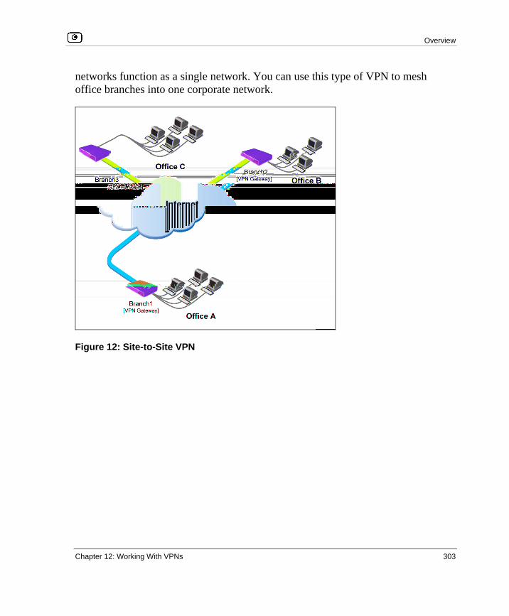
Overview
Chapter 12: Working With VPNs 303
networks function as a single network. You can use this type of VPN to mesh office branches into one corporate network.
Figure 12: Site-to-Site VPN

Overview
304 Check Point Safe@Office User Guide
To create a Site-to-Site VPN with two VPN sites
1. On the first VPN site’s Safe@Office appliance, do the following:
a. Define the second VPN site as a Site-to-Site VPN Gateway, or create a PPPoE tunnel to the second VPN site, using the procedure Adding and Editing VPN Sites on page 312.
b. Enable the Remote Access VPN Server using the procedure Setting Up Your Safe@Office Appliance as a Remote Access VPN Server on page 307.
2. On the second VPN site’s Safe@Office appliance, do the following:
a. Define the first VPN site as a Site-to-Site VPN Gateway, or create a PPPoE tunnel to the first VPN site, using the procedure Adding and Editing VPN Sites on page 312.
b. Then enable the Remote Access VPN Server using the procedure Setting Up Your Safe@Office Appliance as a Remote Access VPN Server on page 307.

Overview
Chapter 12: Working With VPNs 305
Remote Access VPNs A Remote Access VPN consists of one Remote Access VPN Server or Site-to-Site VPN Gateway, and one or more Remote Access VPN Clients. You can use this type of VPN to make an office network remotely available to authorized users, such as employees working from home, who connect to the office Remote Access VPN Server with their Remote Access VPN Clients.
Figure 13: Remote Access VPN

Overview
306 Check Point Safe@Office User Guide
To create a Remote Access VPN with two VPN sites
1. On the remote user VPN site's Safe@Office appliance, add the office Remote Access VPN Server as a Remote Access VPN site.
See Adding and Editing VPN Sites on page 312.
The remote user's Safe@Office appliance will act as a Remote Access VPN Client.
2. On the office VPN site's Safe@Office appliance, enable the Remote Access VPN Server.
See Setting Up Your Safe@Office Appliance as a Remote Access VPN Server on page 307.
Internal VPN Server You can use your Safe@Office appliance as an internal VPN Server, for enhanced wired and wireless security. When the internal VPN Server is enabled, internal network PCs and PDAs with SecuRemote VPN Client software installed can establish a Remote Access VPN session to the gateway. This means that connections from internal network users to the gateway can be encrypted and authenticated.
The benefits of using the internal VPN Server are two-fold:
• Accessibility
Using SecuRemote, you can enjoy a secure connection from anywhere—in your wireless network or on the road—without changing any settings. The standard is completely transparent and allows you to access company resources the same way, whether you are sitting at your desk or anywhere else.
• Security
Many of today's attacks are increasingly introduced from inside the network. Internal security threats cause outages, downtime, and lost revenue. Wired networks that deal with highly sensitive information—especially networks in public places, such as classrooms—are vulnerable to users trying to hack the internal network.

Setting Up Your Safe@Office Appliance as a VPN Server
Chapter 12: Working With VPNs 307
Using the internal VPN Server, along with a strict security policy for non-VPN users, can enhance security both for wired networks and for wireless networks, which are particularly vulnerable to security breaches.
The internal VPN Server can be used in the Safe@Office 500W wireless appliance, regardless of the wireless security settings. It also can be used in wired appliances, both for wired stations and for wireless stations.
Note: You can enable wireless connections to a wired Safe@Office appliance, by connecting a wireless access point in bridge mode to one of the appliance's internal interfaces. Do not connect computers to the same interface as a wireless access point, since allowing direct access from the wireless network may pose a significant security risk.
For information on setting up your Safe@Office appliance as an internal VPN Server, see Setting Up Your Safe@Office Appliance as a VPN Server on page 307.
Setting Up Your Safe@Office Appliance as a VPN Server
You can make your network available to authorized users connecting from the Internet or from your internal networks, by setting up your Safe@Office appliance as a VPN Server. Users can connect to the VPN Server via Check Point SecuRemote or via a Safe@Office appliance in Remote Access VPN mode.
Enabling the VPN Server for users connecting from your internal networks adds a layer of security to such connections. For example, while you could create a firewall rule allowing a specific user on the DMZ or WLAN to access the LAN, enabling VPN access for the user means that such connections can be encrypted and authenticated. For more information, see Internal VPN Server on page 306.

Setting Up Your Safe@Office Appliance as a VPN Server
308 Check Point Safe@Office User Guide
To set up your Safe@Office appliance as a VPN Server
1. Configure the VPN Server in one or more of the following ways:
• To accept remote access connections from the Internet.
See Configuring the Remote Access VPN Server on page 309.
• To accept connections from your internal networks.
See Configuring the Internal VPN Server on page 310. 2. If you configured the internal VPN Server, install SecuRemote on the desired
internal network computers.
See Installing SecuRemote on page 311.
3. Set up remote VPN access for users.
See Setting Up Remote VPN Access for Users on page 369.
Note: Disabling the VPN Server for a specific type of connection (from the Internet or from internal networks) will cause all existing VPN tunnels of that type to disconnect.

Setting Up Your Safe@Office Appliance as a VPN Server
Chapter 12: Working With VPNs 309
Configuring the Remote Access VPN Server
To configure the Remote Access VPN Server
1. Click VPN in the main menu, and click the VPN Server tab.
The SecuRemote VPN Server page appears.
2. Select the Allow SecuRemote users to connect from the Internet check box.

Setting Up Your Safe@Office Appliance as a VPN Server
310 Check Point Safe@Office User Guide
New check boxes appear.
3. To allow authenticated users connecting from the Internet to bypass NAT when
connecting to your internal network, select the Bypass NAT check box.
4. To allow authenticated users connecting from the Internet to bypass the firewall and access your internal network without restriction, select the Bypass the firewall check box.
5. Click Apply.
The Remote Access VPN Server is enabled for the specified connection types.
Configuring the Internal VPN Server
To configure the internal VPN Server
1. Click VPN in the main menu, and click the VPN Server tab.
The SecuRemote VPN Server page appears.

Setting Up Your Safe@Office Appliance as a VPN Server
Chapter 12: Working With VPNs 311
2. Select the Allow SecuRemote users to connect from my internal networks check box.
New check boxes appear.
3. To allow authenticated users connecting from internal networks to bypass the
firewall and access your internal network without restriction, select the Bypass the firewall check box.
Bypass NAT is always enabled for the internal VPN server, and cannot be disabled.
4. Click Apply.
The internal VPN Server is enabled for the specified connection types.
Installing SecuRemote
If you configured the Remote Access VPN Server to accept connections from your internal networks, you must install the SecuRemote VPN Client on internal network computers that should be allowed to remotely access your network.

Adding and Editing VPN Sites
312 Check Point Safe@Office User Guide
To install SecuRemote
1. Click VPN in the main menu, and click the VPN Server tab.
The SecuRemote VPN Server page appears.
2. Click the Download SecuRemote VPN client link.
The VPN-1 SecuRemote for Safe@Office page opens in a new window.
3. Follow the online instructions to complete installation.
SecuRemote is installed.
For information on using SecuRemote, see the User Help. To access SecuRemote User Help, right-click on the SecuRemote VPN Client icon in the taskbar, select Settings, and then click Help.
Adding and Editing VPN Sites
To add or edit VPN sites
1. Click VPN in the main menu, and click the VPN Sites tab.

Adding and Editing VPN Sites
Chapter 12: Working With VPNs 313
The VPN Sites page appears with a list of VPN sites.
2. Do one of the following:
• To add a VPN site, click New Site.
• To edit a VPN site, click Edit in the desired VPN site’s row. The Safe@Office VPN Site Wizard opens, with the Welcome to the VPN Site Wizard dialog box displayed.

Adding and Editing VPN Sites
314 Check Point Safe@Office User Guide
3. Do one of the following:
• Select Remote Access VPN to establish remote access from your Remote Access VPN Client to a Remote Access VPN Server.
• Select Site-to-Site VPN to create a permanent bi-directional connection to another Site-to-Site VPN Gateway.
4. Click Next.
Configuring a Remote Access VPN Site If you selected Remote Access VPN, the VPN Gateway Address dialog box appears.
1. Enter the IP address of the Remote Access VPN Server to which you want to
connect, as given to you by the network administrator.
2. To allow the VPN site to bypass the firewall and access your internal network without restriction, select the Bypass the firewall check box.
3. Click Next.

Adding and Editing VPN Sites
Chapter 12: Working With VPNs 315
The VPN Network Configuration dialog box appears.
4. Specify how you want to obtain the VPN network configuration. Refer to VPN
Network Configuration Fields on page 323.
5. Click Next. The following things happen in the order below:
• If you chose Specify Configuration, a second VPN Network Configuration dialog box appears.

Adding and Editing VPN Sites
316 Check Point Safe@Office User Guide
Complete the fields using the information in VPN Network Configuration Fields on page 323 and click Next.
• The Authentication Method dialog box appears.
6. Complete the fields using the information in Authentication Methods Fields on
page 325.
7. Click Next.
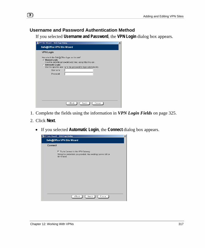
Adding and Editing VPN Sites
Chapter 12: Working With VPNs 317
Username and Password Authentication Method If you selected Username and Password, the VPN Login dialog box appears.
1. Complete the fields using the information in VPN Login Fields on page 325.
2. Click Next.
• If you selected Automatic Login, the Connect dialog box appears.

Adding and Editing VPN Sites
318 Check Point Safe@Office User Guide
Do the following:
1) To try to connect to the Remote Access VPN Server, select the Try to Connect to the VPN Gateway check box.
This allows you to test the VPN connection.
Warning: If you try to connect to the VPN site before completing the wizard, all existing tunnels will be terminated.
2) Click Next. If you selected Try to Connect to the VPN Gateway, the Connecting… screen appears, and then the Contacting VPN Site screen appears.
• The Site Name dialog box appears.
3. Enter a name for the VPN site.
You may choose any name.
4. Click Next.
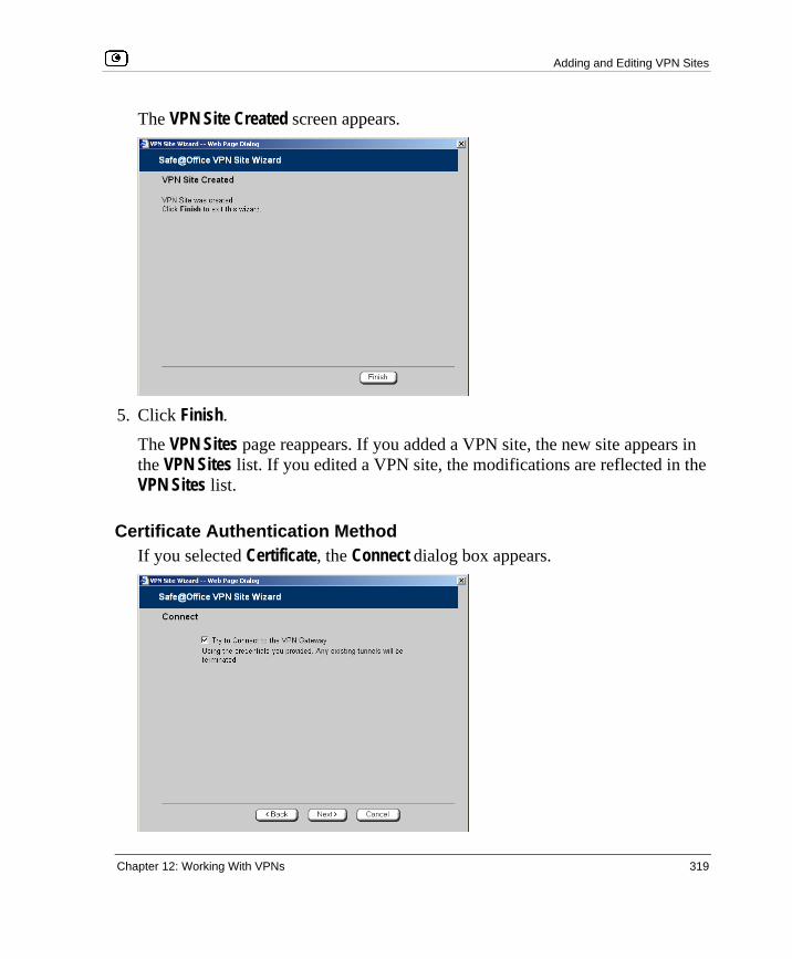
Adding and Editing VPN Sites
Chapter 12: Working With VPNs 319
The VPN Site Created screen appears.
5. Click Finish.
The VPN Sites page reappears. If you added a VPN site, the new site appears in the VPN Sites list. If you edited a VPN site, the modifications are reflected in the VPN Sites list.
Certificate Authentication Method If you selected Certificate, the Connect dialog box appears.

Adding and Editing VPN Sites
320 Check Point Safe@Office User Guide
1. To try to connect to the Remote Access VPN Server, select the Try to Connect to the VPN Gateway check box.
This allows you to test the VPN connection.
Warning: If you try to connect to the VPN site before completing the wizard, all existing tunnels will be terminated.
2. Click Next. If you selected Try to Connect to the VPN Gateway, the Connecting… screen appears, and then the Contacting VPN Site screen appears.
The Site Name dialog box appears.
3. Enter a name for the VPN site.
You may choose any name.
4. Click Next.

Adding and Editing VPN Sites
Chapter 12: Working With VPNs 321
The VPN Site Created screen appears.
5. Click Finish.
The VPN Sites page reappears. If you added a VPN site, the new site appears in the VPN Sites list. If you edited a VPN site, the modifications are reflected in the VPN Sites list.
RSA SecurID Authentication Method If you selected RSA SecurID, the Site Name dialog box appears.

Adding and Editing VPN Sites
322 Check Point Safe@Office User Guide
1. Enter a name for the VPN site.
You may choose any name.
2. Click Next. The VPN Site Created screen appears.
3. Click Finish.
The VPN Sites page reappears. If you added a VPN site, the new site appears in the VPN Sites list. If you edited a VPN site, the modifications are reflected in the VPN Sites list.

Adding and Editing VPN Sites
Chapter 12: Working With VPNs 323
Table 63: VPN Network Configuration Fields
In this field… Do this…
Download
Configuration
Click this option to obtain the network configuration by downloading it from the VPN site.
This option will automatically configure your VPN settings, by downloading
the network topology definition from the Remote Access VPN Server.
Note: Downloading the network configuration is only possible if you are
connecting to a Check Point VPN-1 or Safe@Office Site-to-Site VPN
Gateway.
Specify
Configuration
Click this option to provide the network configuration manually.
Route All Traffic Click this option to route all network traffic through the VPN site.
For example, if your VPN consists of a central office and a number of
remote offices, and the remote offices are only allowed to access Internet
resources through the central office, you can choose to route all traffic from
the remote offices through the central office.
Note: You can only configure one VPN site to route all traffic.

Adding and Editing VPN Sites
324 Check Point Safe@Office User Guide
In this field… Do this…
Route Based VPN Click this option to create a virtual tunnel interface (VTI) for this site, so
that it can participate in a route-based VPN.
Route-based VPNs allow routing connections over VPN tunnels, so that
remote VPN sites can participate in dynamic or static routing schemes.
This improves network and VPN management efficiency for large
networks.
For constantly changing networks, it is recommended to use a route-based
VPN combined with OSPF dynamic routing. This enables you to make
frequent changes to the network topology, such as adding an internal
network, without having to reconfigure static routes.
OSPF is enabled using CLI. For information on using CLI, see Controlling the Appliance via the Command Line on page 388. For information on
the relevant commands for OSPF, refer to the Embedded NGX CLI
Reference Guide.
This option is only available for when configuring a Site-to-Site VPN
gateway.
Destination network Type up to three destination network addresses at the VPN site to which
you want to connect.
Subnet mask Select the subnet masks for the destination network addresses.
Note: Obtain the destination networks and subnet masks from the VPN
site’s system administrator.
Backup Gateway Type the name of the VPN site to use if the primary VPN site fails.

Adding and Editing VPN Sites
Chapter 12: Working With VPNs 325
Table 64: Authentication Methods Fields
In this field… Do this…
Username and
Password
Select this option to use a user name and password for VPN
authentication.
In the next step, you can specify whether you want to log on to the VPN
site automatically or manually.
Certificate Select this option to use a certificate for VPN authentication.
If you select this option, a certificate must have been installed. (Refer to
Installing a Certificate on page 348 for more information about
certificates and instructions on how to install a certificate.)
RSA SecurID
Token
Select this option to use an RSA SecurID token for VPN authentication.
When authenticating to the VPN site, you must enter a four-digit PIN code
and the SecurID passcode shown in your SecurID token's display. The
RSA SecurID token generates a new passcode every minute.
SecurID is only supported in Remote Access manual login mode.

Adding and Editing VPN Sites
326 Check Point Safe@Office User Guide
Table 65: VPN Login Fields
In this field… Do this…
Manual Login Click this option to configure the site for Manual Login.
Manual Login connects only the computer you are currently logged onto to
the VPN site, and only when the appropriate user name and password
have been entered. For further information on Automatic and Manual
Login, see, Logging on to a VPN Site on page 344.
Automatic Login Click this option to enable the Safe@Office appliance to log on to the VPN
site automatically.
You must then fill in the Username and Password fields.
Automatic Login provides all the computers on your internal network with
constant access to the VPN site. For further information on Automatic and
Manual Login, see Logging on to a VPN Site on page 344.
Username Type the user name to be used for logging on to the VPN site.
Password Type the password to be used for logging on to the VPN site.

Adding and Editing VPN Sites
Chapter 12: Working With VPNs 327
Configuring a Site-to-Site VPN Gateway If you selected Site-to-Site VPN, the VPN Gateway Address dialog box appears.
1. Complete the fields using the information in VPN Gateway Address Fields on
page 338.
2. Click Next. The VPN Network Configuration dialog box appears.

Adding and Editing VPN Sites
328 Check Point Safe@Office User Guide
3. Specify how you want to obtain the VPN network configuration. Refer to VPN Network Configuration Fields on page 323.
4. Click Next.
• If you chose Specify Configuration, a second VPN Network Configuration dialog box appears.
Complete the fields using the information in VPN Network Configuration Fields on page 323, and then click Next.

Adding and Editing VPN Sites
Chapter 12: Working With VPNs 329
• If you chose Route Based VPN, the Route Based VPN dialog box appears.
Complete the fields using the information in Route Based VPN Fields on page 339, and then click Next.
• The Authentication Method dialog box appears.
5. Complete the fields using the information in Authentication Methods Fields on
page 340.
6. Click Next.

Adding and Editing VPN Sites
330 Check Point Safe@Office User Guide
Shared Secret Authentication Method If you selected Shared Secret, the Authentication dialog box appears.
If you chose Download Configuration, the dialog box contains additional fields.
1. Complete the fields using the information in VPN Authentication Fields on
page 340 and click Next.

Adding and Editing VPN Sites
Chapter 12: Working With VPNs 331
The Security Methods dialog box appears.
2. To configure advanced security settings, click Show Advanced Settings.
New fields appear.
3. Complete the fields using the information in Security Methods Fields on page
340 and click Next.

Adding and Editing VPN Sites
332 Check Point Safe@Office User Guide
The Connect dialog box appears.
4. To try to connect to the Remote Access VPN Server, select the Try to Connect to
the VPN Gateway check box.
This allows you to test the VPN connection.
Warning: If you try to connect to the VPN site before completing the wizard, all existing tunnels will be terminated.
5. Click Next.
• If you selected Try to Connect to the VPN Gateway, the Connecting… screen appears, and then the Contacting VPN Site screen appears.

Adding and Editing VPN Sites
Chapter 12: Working With VPNs 333
• The Site Name dialog box appears.
6. Enter a name for the VPN site.
You may choose any name.
7. To keep the tunnel to the VPN site alive even if there is no network traffic between the Safe@Office appliance and the VPN site, select Keep this site alive.
8. Click Next.

Adding and Editing VPN Sites
334 Check Point Safe@Office User Guide
• If you selected Keep this site alive, and previously you chose Download Configuration, the "Keep Alive" Configuration dialog box appears.
Do the following:
1) Type up to three IP addresses which the Safe@Office appliance should ping in order to keep the tunnel to the VPN site alive.
2) Click Next. • The VPN Site Created screen appears.
9. Click Finish.
The VPN Sites page reappears. If you added a VPN site, the new site appears in the VPN Sites list. If you edited a VPN site, the modifications are reflected in the VPN Sites list.
Certificate Authentication Method If you selected Certificate, the following things happen:

Adding and Editing VPN Sites
Chapter 12: Working With VPNs 335
• If you chose Download Configuration, the Authentication dialog box appears.
Complete the fields using the information in VPN Authentication Fields on page 340 and click Next.
• The Security Methods dialog box appears.
1. To configure advanced security settings, click Show Advanced Settings.

Adding and Editing VPN Sites
336 Check Point Safe@Office User Guide
New fields appear.
2. Complete the fields using the information in Security Methods Fields on page
340 and click Next. The Connect dialog box appears.
3. To try to connect to the Remote Access VPN Server, select the Try to Connect to
the VPN Gateway check box.
This allows you to test the VPN connection.

Adding and Editing VPN Sites
Chapter 12: Working With VPNs 337
Warning: If you try to connect to the VPN site before completing the wizard, all existing tunnels will be terminated.
4. Click Next.
• If you selected Try to Connect to the VPN Gateway, the following things happen:
The Connecting… screen appears.
• The Contacting VPN Site screen appears.
• The Site Name dialog box appears.
5. Enter a name for the VPN site.
You may choose any name.
6. To keep the tunnel to the VPN site alive even if there is no network traffic between the Safe@Office appliance and the VPN site, select Keep this site alive.
7. Click Next.
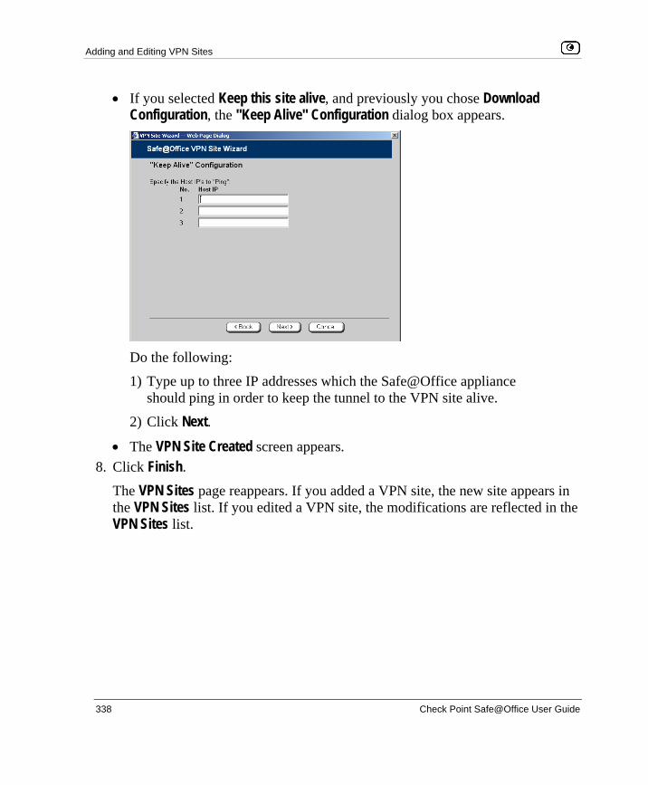
Adding and Editing VPN Sites
338 Check Point Safe@Office User Guide
• If you selected Keep this site alive, and previously you chose Download Configuration, the "Keep Alive" Configuration dialog box appears.
Do the following:
1) Type up to three IP addresses which the Safe@Office appliance should ping in order to keep the tunnel to the VPN site alive.
2) Click Next. • The VPN Site Created screen appears.
8. Click Finish.
The VPN Sites page reappears. If you added a VPN site, the new site appears in the VPN Sites list. If you edited a VPN site, the modifications are reflected in the VPN Sites list.

Adding and Editing VPN Sites
Chapter 12: Working With VPNs 339
Table 66: VPN Gateway Address Fields
In this field… Do this…
Gateway Address Type the IP address of the Site-to-Site VPN Gateway to which you want
to connect, as given to you by the network administrator.
Bypass NAT Select this option to allow the VPN site to bypass NAT when connecting
to your internal network.
This option is selected by default.
Bypass the
firewall
Select this option to allow the VPN site to bypass the firewall and access
your internal network without restriction.
Table 67: Route Based VPN Fields
In this field… Do this…
Tunnel Local IP Type a local IP address for this end of the VPN tunnel.
Tunnel Remote IP Type the IP address of the remote end of the VPN tunnel.
OSPF Cost Type the cost of this link for dynamic routing purposes.
The default value is 10.
If OSPF is not enabled, this setting is not used. OSPF is enabled using
the Safe@Office command line interface (CLI). For information on using
CLI, see Controlling the Appliance via the Command Line on page
388. For information on the relevant commands for OSPF, refer to the
Embedded NGX CLI Reference Guide.

Adding and Editing VPN Sites
340 Check Point Safe@Office User Guide
Table 68: Authentication Methods Fields
In this field… Do this…
Shared Secret Select this option to use a shared secret for VPN authentication.
A shared secret is a string used to identify VPN sites to each other.
Certificate Select this option to use a certificate for VPN authentication.
If you select this option, a certificate must have been installed. (Refer to
Installing a Certificate on page 348 for more information about
certificates and instructions on how to install a certificate.)
Table 69: VPN Authentication Fields
In this field… Do this…
Topology User Type the topology user’s user name.
Topology
Password
Type the topology user’s password.
Use Shared
Secret
Type the shared secret to use for secure communications with the VPN
site.
This shared secret is a string used to identify the VPN sites to each other.
The secret can contain spaces and special characters.

Adding and Editing VPN Sites
Chapter 12: Working With VPNs 341
Table 70: Security Methods Fields
In this field… Do this…
Phase 1
Security Methods Select the encryption and integrity algorithm to use for IKE negotiations:
• Automatic. The Safe@Office appliance automatically selects the best security methods supported by the site. This is the default.
• A specific algorithm
Diffie-Hellman
group
Select the Diffie-Hellman group to use:
• Automatic. The Safe@Office appliance automatically selects a group. This is the default.
• A specific group
A group with more bits ensures a stronger key but lowers performance.
Renegotiate every Type the interval in minutes between IKE Phase-1 key negotiations. This
is the IKE Phase-1 SA lifetime.
A shorter interval ensures higher security, but impacts heavily on
performance. Therefore, it is recommended to keep the SA lifetime
around its default value.
The default value is 1440 minutes (one day).
Phase 2
Security Methods Select the encryption and integrity algorithm to use for VPN traffic:
• Automatic. The Safe@Office appliance automatically selects the best security methods supported by the site. This is the default.
• A specific algorithm

Adding and Editing VPN Sites
342 Check Point Safe@Office User Guide
In this field… Do this…
Perfect Forward
Secrecy
Specify whether to enable Perfect Forward Secrecy (PFS), by selecting
one of the following:
• Enabled. PFS is enabled. The Diffie-Hellman group field is enabled.
• Disabled. PFS is disabled. This is the default.
Enabling PFS will generate a new Diffie-Hellman key during IKE Phase 2
and renew the key for each key exchange.
PFS increases security but lowers performance. It is recommended to
enable PFS only in situations where extreme security is required.
Diffie-Hellman
group
Select the Diffie-Hellman group to use:
• Automatic. The Safe@Office appliance automatically selects a group. This is the default.
• A specific group
A group with more bits ensures a stronger key but lowers performance.
Renegotiate every Type the interval in seconds between IPSec SA key negotiations. This is
the IKE Phase-2 SA lifetime.
A shorter interval ensures higher security.
The default value is 3600 seconds (one hour).

Deleting a VPN Site
Chapter 12: Working With VPNs 343
Deleting a VPN Site
To delete a VPN site
1. Click VPN in the main menu, and click the VPN Sites tab.
The VPN Sites page appears, with a list of VPN sites.
2. In the desired VPN site’s row, click the Erase icon.
A confirmation message appears.
3. Click OK.
The VPN site is deleted.
Enabling/Disabling a VPN Site
You can only connect to VPN sites that are enabled.
To enable/disable a VPN site
1. Click VPN in the main menu, and click the VPN Sites tab.
The VPN Sites page appears, with a list of VPN sites.
2. To enable a VPN site, do the following:
a. Click the icon in the desired VPN site’s row.
A confirmation message appears.
b. Click OK.
The icon changes to , and the VPN site is enabled.

Logging on to a Remote Access VPN Site
344 Check Point Safe@Office User Guide
3. To disable a VPN site, do the following:
Note: Disabling a VPN site eliminates the tunnel and erases the network topology.
a. Click the icon in the desired VPN site’s row.
A confirmation message appears.
b. Click OK.
The icon changes to , and the VPN site is disabled.
Logging on to a Remote Access VPN Site
You need to manually log on to Remote Access VPN Servers configured for Manual Login. You do not need to manually log on to a Remote Access VPN Server configured for Automatic Login or a Site-to-Site VPN Gateway: all the computers on your network have constant access to it.
Manual Login can be done through either the Safe@Office Portal or the my.vpn page. When you log on and traffic is sent to the VPN site, a VPN tunnel is established. Only the computer from which you logged on can use the tunnel. To share the tunnel with other computers in your home network, you must log on to the VPN site from those computers, using the same user name and password.
Note: You must use a single user name and password for each VPN destination gateway.


Logging on to a Remote Access VPN Site
346 Check Point Safe@Office User Guide
• If the Safe@Office appliance is configured to automatically download the network configuration, the Safe@Office appliance downloads the network configuration.
• If when adding the VPN site you specified a network configuration, the Safe@Office appliance attempts to create a tunnel to the VPN site.
• Once the Safe@Office appliance has finished connecting, the VPN Login Status box appears. The Status field displays “Connected”.
• The VPN Login Status box remains open until you manually log off the
VPN site.
Logging on through the my.vpn page
Note: You don’t need to know the my.firewall page administrator’s password in order to use the my.vpn page.
To manually log on to a VPN site through the my.vpn page
1. Direct your Web browser to http://my.vpn

Logging on to a Remote Access VPN Site
Chapter 12: Working With VPNs 347
The VPN Login screen appears.
2. In the Site Name list, select the site to which you want to log on.
3. Enter your user name and password in the appropriate fields.
4. Click Login.
• If the Safe@Office appliance is configured to automatically download the network configuration, the Safe@Office appliance downloads the network configuration.
• If when adding the VPN site you specified a network configuration, the Safe@Office appliance attempts to create a tunnel to the VPN site.
• The VPN Login Status box appears. The Status field tracks the connection’s progress.
• Once the Safe@Office appliance has finished connecting, the Status field changes to “Connected”.
• The VPN Login Status box remains open until you manually log off of the VPN site.

Logging off a Remote Access VPN Site
348 Check Point Safe@Office User Guide
Logging off a Remote Access VPN Site
You need to manually log off a VPN site, if it is a Remote Access VPN site configured for Manual Login.
To log off a VPN site
• In the VPN Login Status box, click Logout. All open tunnels from the Safe@Office appliance to the VPN site are closed, and the VPN Login Status box closes.
Note: Closing the browser or dismissing the VPN Login Status box will also terminate the VPN session within a short time.
Installing a Certificate
A digital certificate is a secure means of authenticating the Safe@Office appliance to other Site-to-Site VPN Gateways. The certificate is issued by the Certificate Authority (CA) to entities such as gateways, users, or computers. The entity then uses the certificate to identify itself and provide verifiable information.
For instance, the certificate includes the Distinguished Name (DN) (identifying information) of the entity, as well as the public key (information about itself). After two entities exchange and validate each other's certificates, they can begin encrypting information between themselves using the public keys in the certificates.
The certificate also includes a fingerprint, a unique text used to identify the certificate. You can email your certificate's fingerprint to the remote user. Upon connecting to the Safe@Office VPN Server for the first time, the entity should check that the VPN peer's fingerprint displayed in the SecuRemote VPN Client is identical to the fingerprint received.

Installing a Certificate
Chapter 12: Working With VPNs 349
The Safe@Office appliance supports certificates encoded in the PKCS#12 (Personal Information Exchange Syntax Standard) format, and enables you to install such certificates in the following ways:
• By generating a self-signed certificate.
See Generating a Self-Signed Certificate on page 349.
• By importing a certificate.
The PKCS#12 file you import must have a ".p12" file extension. If you do not have such a PKCS#12 file, obtain one from your network security administrator.
See Importing a Certificate on page 353.
Note: To use certificates authentication, each Safe@Office appliance should have a unique certificate. Do not use the same certificate for more than one gateway.
Note: If your Safe@Office appliance is centrally managed, a certificate is automatically generated and downloaded to your appliance. In this case, there is no need to generate a self-signed certificate.
Generating a Self-Signed Certificate
To generate a self-signed certificate
1. Click VPN in the main menu, and click the Certificate tab.

Installing a Certificate
350 Check Point Safe@Office User Guide
The Certificate page appears.
2. Click Install Certificate.
The Safe@Office Certificate Wizard opens, with the Certificate Wizard dialog box displayed.
3. Click Generate a self-signed security certificate for this gateway.

Installing a Certificate
Chapter 12: Working With VPNs 351
The Create Self-Signed Certificate dialog box appears.
4. Complete the fields using the information in the table below.
5. Click Next. The Safe@Office appliance generates the certificate. This may take a few seconds.
The Done dialog box appears, displaying the certificate's details.
6. Click Finish.

Installing a Certificate
352 Check Point Safe@Office User Guide
The Safe@Office appliance installs the certificate. If a certificate is already installed, it is overwritten.
The Certificate Wizard closes.
The Certificates page displays the following information:
• The gateway's certificate
• The gateway's name
• The gateway certificate's fingerprint
• The CA's certificate
• The name of the CA that issued the certificate (in this case, the Safe@Office gateway)
• The CA certificate's fingerprint
• The starting and ending dates between which the gateway's certificate and the CA's certificate are valid

Installing a Certificate
Chapter 12: Working With VPNs 353
Table 71: Certificate Fields
In this field… Do this…
Country Select your country from the drop-down list.
Organization
Name
Type the name of your organization.
Organizational Unit Type the name of your division.
Gateway Name Type the gateway's name. This name will appear on the certificate, and will
be visible to remote users inspecting the certificate.
This field is filled in automatically with the gateway's MAC address. If
desired, you can change this to a more descriptive name.
Valid Until Use the drop-down lists to specify the month, day, and year when this
certificate should expire.
Note: You must renew the certificate when it expires.
Importing a Certificate
To install a certificate
1. Click VPN in the main menu, and click the Certificate tab.
The Certificate page appears.
2. Click Install Certificate.
The Safe@Office Certificate Wizard opens, with the Certificate Wizard dialog box displayed.
3. Click Import a security certificate in PKCS#12 format.
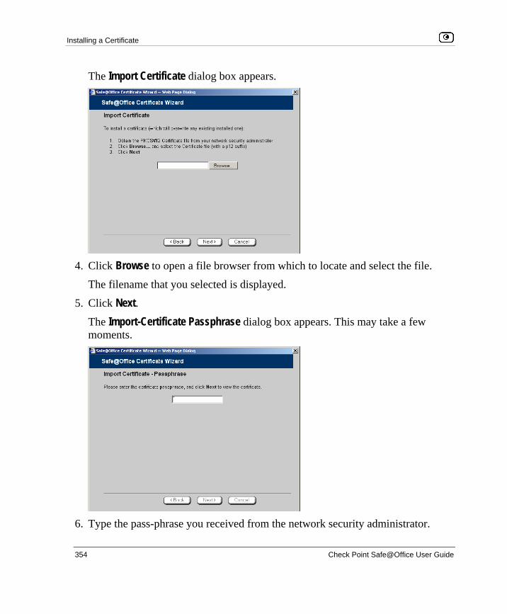
Installing a Certificate
354 Check Point Safe@Office User Guide
The Import Certificate dialog box appears.
4. Click Browse to open a file browser from which to locate and select the file.
The filename that you selected is displayed.
5. Click Next. The Import-Certificate Passphrase dialog box appears. This may take a few moments.
6. Type the pass-phrase you received from the network security administrator.

Uninstalling a Certificate
Chapter 12: Working With VPNs 355
7. Click Next. The Done dialog box appears, displaying the certificate's details.
8. Click Finish.
The Safe@Office appliance installs the certificate. If a certificate is already installed, it is overwritten.
The Certificate Wizard closes.
The Certificates page displays the following information:
• The gateway's certificate
• The gateway's name
• The gateway certificate's fingerprint
• The CA's certificate
• The name of the CA that issued the certificate
• The CA certificate's fingerprint
• The starting and ending dates between which the gateway's certificate and the CA's certificate are valid
Uninstalling a Certificate
If you uninstall the certificate, no certificate will exist on the Safe@Office appliance, and you will not be able to connect to the VPN if a certificate is required.
You cannot uninstall the certificate if there is a VPN site currently defined to use certificate authentication.
Note: If you want to replace a currently-installed certificate, there is no need to uninstall the certificate first. When you install the new certificate, the old certificate will be overwritten.

Viewing VPN Tunnels
356 Check Point Safe@Office User Guide
To uninstall a certificate
1. Click VPN in the main menu, and click the Certificate tab.
The Certificate page appears with the name of the currently installed certificate.
2. Click Uninstall. A confirmation message appears.
3. Click OK.
The certificate is uninstalled.
A success message appears.
4. Click OK.
Viewing VPN Tunnels
You can view a list of currently established VPN tunnels. VPN tunnels are created and closed as follows:
• Remote Access VPN sites configured for Automatic Login and Site-to-Site VPN Gateways A tunnel is created whenever your computer attempts any kind of communication with a computer at the VPN site. The tunnel is closed when not in use for a period of time.
Note: Although the VPN tunnel is automatically closed, the site remains open, and if you attempt to communicate with the site, the tunnel will be reestablished.
• Remote Access VPN sites configured for Manual Login A tunnel is created whenever your computer attempts any kind of communication with a computer at the VPN site, after you have manually logged on to the site. All open tunnels connecting to the site are closed when you manually log off.

Viewing VPN Tunnels
Chapter 12: Working With VPNs 357
To view VPN tunnels
1. Click Reports in the main menu, and click the VPN Tunnels tab.
The VPN Tunnels page appears with a table of open tunnels to VPN sites.
The VPN Tunnels page includes the information described in the table below.
2. To refresh the table, click Refresh.
Table 72: VPN Tunnels Page Fields
This field… Displays…
Type The currently active security protocol (IPSEC).
Source
The IP address or address range of the entity from which the tunnel
originates.
The entity's type is indicated by an icon. See VPN Tunnel Icons on page
358.

Viewing VPN Tunnels
358 Check Point Safe@Office User Guide
This field… Displays…
Destination The IP address or address range of the entity to which the tunnel is
connected.
The entity's type is indicated by an icon. See VPN Tunnel Icons on page
358.
Security The type of encryption used to secure the connection, and the type of
Message Authentication Code (MAC) used to verify the integrity of the
message. This information is presented in the following format: Encryption
type/Authentication type
Note: All VPN settings are automatically negotiated between the two sites.
The encryption and authentication schemes used for the connection are the
strongest of those used at the two sites.
Your Safe@Office appliance supports AES, 3DES, and DES encryption
schemes, and MD5 and SHA authentication schemes.
Established The time at which the tunnel was established.
This information is presented in the format hh:mm:ss, where:
hh=hours
mm=minutes
ss=seconds
Table 73: VPN Tunnels Icons
This icon… Represents…
This gateway

Viewing IKE Traces for VPN Connections
Chapter 12: Working With VPNs 359
This icon… Represents…
A network for which an IKE Phase-2 tunnel was negotiated
A Remote Access VPN Server
A Site-to-Site VPN Gateway
A remote access VPN user
Viewing IKE Traces for VPN Connections
If you are experiencing VPN connection problems, you can save a trace of IKE (Internet Key Exchange) negotiations to a file, and then use the free IKE View tool to view the file.
The IKE View tool is available for the Windows platform.
Note: Before viewing IKE traces, it is recommended to do the following:
• The Safe@Office appliance stores traces for all recent IKE negotiations. If you want to view only new IKE trace data, clear all IKE trace data currently stored on the Safe@Office appliance.
• Close all existing VPN tunnels except for the problematic tunnel, so as to make it easier to locate the problematic tunnel's IKE negotiation trace in the exported file.
To clear all currently-stored IKE traces
1. Click Reports in the main menu, and click the VPN Tunnels tab.
The VPN Tunnels page appears with a table of open tunnels to VPN sites.
2. Click Clear IKE Trace.
All IKE trace data currently stored on the Safe@Office appliance is cleared.
Viewing IKE Traces for VPN Connections
360 Check Point Safe@Office User Guide
To view the IKE trace for a connection
1. Establish a VPN tunnel to the VPN site with which you are experiencing connection problems.
For information on when and how VPN tunnels are established, see Viewing VPN Tunnels on page 356.
2. Click Reports in the main menu, and click the VPN Tunnels tab.
The VPN Tunnels page appears with a table of open tunnels to VPN sites.
3. Click Save IKE Trace.
A standard File Download dialog box appears.
4. Click Save.
The Save As dialog box appears.
5. Browse to a destination directory of your choice.
6. Type a name for the *.elg file and click Save.
The *.elg file is created and saved to the specified directory. This file contains the IKE traces of all currently-established VPN tunnels.
7. Use the IKE View tool to open and view the *.elg file, or send the file to technical support.

Changing Your Password
Chapter 13: Managing Users 361
Chapter 13
This chapter describes how to manage Safe@Office appliance users. You can define multiple users, set their passwords, and assign them various permissions.
This chapter includes the following topics: Changing Your Password .........................................................................361 Adding and Editing Users ........................................................................363 Adding Quick Guest HotSpot Users.........................................................367 Viewing and Deleting Users.....................................................................369 Setting Up Remote VPN Access for Users...............................................369 Using RADIUS Authentication ................................................................370 Configuring the RADIUS Vendor-Specific Attribute ..............................374
Changing Your Password
You can change your password at any time.
To change your password
1. Click Users in the main menu, and click the Internal Users tab.
Managing Users

Changing Your Password
362 Check Point Safe@Office User Guide
The Internal Users page appears.
2. In the row of your username, click Edit.
The Account Wizard opens displaying the Set User Details dialog box.
3. Edit the Password and Confirm password fields.

Adding and Editing Users
Chapter 13: Managing Users 363
Note: Use 5 to 25 characters (letters or numbers) for the new password.
4. Click Next. The Set User Permissions dialog box appears.
5. Click Finish.
Your changes are saved.
Adding and Editing Users
This procedure explains how to add and edit users.
For information on quickly adding guest HotSpot users via a shortcut that the Safe@Office appliance provides, see Adding Quick Guest HotSpot Users on page 367.
To add or edit a user
1. Click Users in the main menu, and click the Internal Users tab.

Adding and Editing Users
364 Check Point Safe@Office User Guide
The Internal Users page appears.
2. Do one of the following:
• To create a new user, click New User. • To edit an existing user, click Edit next to the desire user. The Account Wizard opens displaying the Set User Details dialog box.
3. Complete the fields using the information in Set User Details Fields on page
365.
4. Click Next.

Adding and Editing Users
Chapter 13: Managing Users 365
The Set User Permissions dialog box appears.
The options that appear on the page are dependant on the software and services you are using.
5. Complete the fields using the information in Set User Permissions Fields on page 366.
6. Click Finish.
The user is saved.
Table 74: Set User Details Fields
In this field… Do this…
Username Enter a username for the user.
Password Enter a password for the user. Use five to 25 characters (letters or
numbers) for the new password.
Confirm Password Re-enter the user’s password.

Adding and Editing Users
366 Check Point Safe@Office User Guide
In this field… Do this…
Expires On To specify an expiration time for the user, select this option and specify
the expiration date and time in the fields provided.
When the user account expires, it is locked, and the user can no longer
log on to the Safe@Office appliance.
If you do not select this option, the user will not expire.
Table 75: Set User Permissions Fields
In this field... Do this...
Administrator Level Select the user’s level of access to the Safe@Office Portal.
The levels are:
• No Access: The user cannot access the Safe@Office Portal. • Read/Write: The user can log on to the Safe@Office Portal
and modify system settings. • Read Only: The user can log on to the Safe@Office Portal,
but cannot modify system settings or export the appliance configuration via the Setup>Tools page. For example, you could assign this administrator level to technical support personnel who need to view the Event Log.
The default level is No Access.
The “admin” user’s Administrator Level (Read/Write) cannot be
changed.
VPN Remote
Access
Select this option to allow the user to connect to this Safe@Office
appliance using their VPN client.
For further information on setting up VPN remote access, see Setting Up Remote VPN Access for Users on page 369.

Adding Quick Guest HotSpot Users
Chapter 13: Managing Users 367
Web Filtering
Override
Select this option to allow the user to override Web Filtering.
This option only appears if the Web Filtering service is defined.
This option cannot be changed for the “admin” user.
HotSpot Access Select this option to allow the user to log on to the My HotSpot page.
For information on Secure HotSpot, see Configuring Secure HotSpot on page 256.
This option only appears in Safe@Office 500 with Power Pack.
Adding Quick Guest HotSpot Users
The Safe@Office appliance provides a shortcut for quickly adding a guest HotSpot user. This is useful in situations where you want to grant temporary network access to guests, for example in an Internet café. The shortcut also enables printing the guest user's details in one click.
By default, the quick guest user has the following characteristics:
• Username in the format guest<number>, where <number> is a unique three-digit number.
For example: guest123
• Randomly generated password
• Expires in 24 hours
• Administration Level: No Access
• Permissions: HotSpot Access only
For information on configuring Secure HotSpot, see Using Secure HotSpot on page 256.

Adding Quick Guest HotSpot Users
368 Check Point Safe@Office User Guide
To quickly create a guest user
1. Click Users in the main menu, and click the Internal Users tab.
The Internal Users page appears.
2. Click Quick Guest. The Account Wizard opens displaying the Save Quick Guest dialog box.
3. In the Expires field, click on the arrows to specify the expiration date and time.
4. To print the user details, click Print. 5. Click Finish.
The guest user is saved.
You can edit the guest user's details and permissions using the procedure Adding and Editing Users on page 363.

Viewing and Deleting Users
Chapter 13: Managing Users 369
Viewing and Deleting Users
Note: The “admin” user cannot be deleted.
To view or delete users
1. Click Users in the main menu, and click the Internal Users tab.
The Internal Users page appears with a list of all users and their permissions.
The expiration time of expired users appears in red.
2. To delete a user, do the following:
a) In the desired user’s row, click the Erase icon.
A confirmation message appears.
b) Click OK.
The user is deleted. 3. To delete all expired users, do the following:
a) Click Clear Expired.
A confirmation message appears.
b) Click OK.
The expired users are deleted.
Setting Up Remote VPN Access for Users
If you are using your Safe@Office appliance as a Remote Access VPN Server or as an internal VPN Server, you can allow users to access it remotely through their

Using RADIUS Authentication
370 Check Point Safe@Office User Guide
Remote Access VPN Clients (a Check Point SecureClient, Check Point SecuRemote, or another Embedded NGX appliance).
To set up remote VPN access for a user
1. Enable your VPN Server, using the procedure Setting Up Your Safe@Office Appliance as a VPN Server on page 307.
2. Add or edit the user, using the procedure Adding and Editing Users on page 363.
You must select the VPN Remote Access option.
Using RADIUS Authentication
You can use Remote Authentication Dial-In User Service (RADIUS) to authenticate both Safe@Office appliance users and Remote Access VPN Clients trying to connect to the Safe@Office appliance.
Note: When RADIUS authentication is in use, Remote Access VPN Clients must have a certificate.
When a user tries to log on to the Safe@Office Portal, the Safe@Office appliance sends the entered user name and password to the RADIUS server. The server then checks whether the RADIUS database contains a matching user name and password pair. If so, then the user is logged on.
By default, all RADIUS-authenticated users are assigned the set of permissions specified in the Safe@Office Portal's RADIUS page. However, you can configure the RADIUS server to pass the Safe@Office appliance a specific set of permissions to grant the authenticated user, instead of these default permissions. This is done by configuring the RADIUS Vendor-Specific Attribute (VSA) with a set of attributes containing permission information for specific users. If the VSA is configured for a user, then the RADIUS server passes the VSA to the Embedded NGX gateway as part of the response to the authentication request, and the gateway assigns the user permissions as specified in the VSA. If the VSA is not returned by the RADIUS

Using RADIUS Authentication
Chapter 13: Managing Users 371
server for a specific user, the gateway will use the default permission set for this user.
To use RADIUS authentication
1. Click Users in the main menu, and click the RADIUS tab.
The RADIUS page appears.
2. Complete the fields using the table below.
3. Click Apply.
4. To restore the default RADIUS settings, do the following:
a) Click Default.

Using RADIUS Authentication
372 Check Point Safe@Office User Guide
A confirmation message appears.
b) Click OK.
The RADIUS settings are reset to their defaults. For information on the default values, refer to the table below.
5. To use the RADIUS VSA to assign permissions to users, configure the VSA.
See Configuring the RADIUS Vendor-Specific Attribute on page 374.
Table 76: RADIUS Page Fields
In this field… Do this…
Primary/Secondary RADIUS Server
Configure the primary and secondary RADIUS servers.
By default, the Safe@Office appliance sends a request to the primary
RADIUS server first. If the primary RADIUS server does not respond
after three attempts, the Safe@Office appliance will send the request to
the secondary RADIUS server.
Address Type the IP address of the computer that will run the RADIUS service (one of your network computers) or click the corresponding This Computer button to allow your computer to host the service.
To clear the text box, click Clear.
Port Type the port number on the RADIUS server’s host computer.
The default port number is 1812.
Shared Secret Type the shared secret to use for secure communication with the
RADIUS server.

Using RADIUS Authentication
Chapter 13: Managing Users 373
In this field… Do this…
Realm If your organization uses RADIUS realms, type the realm to append to
RADIUS requests. The realm will be appended to the username as
follows: <username>@<realm>
For example, if you set the realm to “myrealm”, and the user "JohnS"
attempts to log on to the Safe@Office Portal, the Safe@Office
appliance will send the RADIUS server an authentication request with
the username “JohnS@myrealm”.
This field is optional.
Timeout Type the interval of time in seconds between attempts to communicate
with the RADIUS server.
The default value is 3 seconds.
RADIUS User Permissions
If the RADIUS VSA (Vendor-Specific Attribute) is configured for a user,
the fields in this area will have no effect, and the user will be granted
the permissions specified in the VSA.
If the VSA is not configured for the user, the permissions configured in
this area will be used.
Administrator Level Select the level of access to the Safe@Office Portal to assign to all
users authenticated by the RADIUS server.
The levels are:
• No Access: The user cannot access the Safe@Office Portal • Read/Write: The user can log on to the Safe@Office Portal
and modify system settings. • Read Only: The user can log on to the Safe@Office Portal,
but cannot modify system settings.
The default level is No Access.

Configuring the RADIUS Vendor-Specific Attribute
374 Check Point Safe@Office User Guide
In this field… Do this…
Web Filtering
Override
Select this option to allow all users authenticated by the RADIUS server
to override Web Filtering.
This option only appears if the Web Filtering service is defined.
HotSpot Access Select this option to allow the user to access the My HotSpot page.
This option only appears in Safe@Office 500 with Power Pack.
Configuring the RADIUS Vendor-Specific Attribute
For detailed instructions and examples, refer to the "Configuring the RADIUS Vendor-Specific Attribute" white paper.
To assign permissions to specific RADIUS-authenticated users
1. Create a remote access policy as follows:
a) Assign the policy’s VSA (attribute 26) the SofaWare vendor code (6983).
b) For each permission you want to grant, configure the relevant attribute of the VSA with the desired value, as described in the table below.
For example, to assign the user VPN access permissions, set attribute number 2 to “true”.
2. Assign the policy to the desired user or user group.
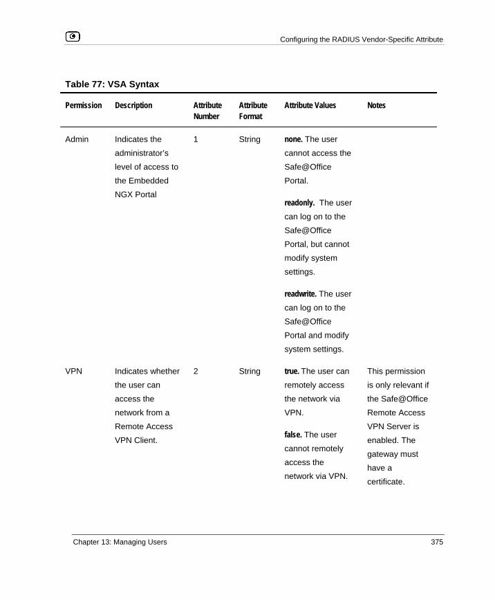
Configuring the RADIUS Vendor-Specific Attribute
Chapter 13: Managing Users 375
Table 77: VSA Syntax
Permission Description Attribute Number
Attribute Format
Attribute Values Notes
Admin Indicates the
administrator’s
level of access to
the Embedded
NGX Portal
1 String none. The user
cannot access the
Safe@Office
Portal.
readonly. The user
can log on to the
Safe@Office
Portal, but cannot
modify system
settings.
readwrite. The user
can log on to the
Safe@Office
Portal and modify
system settings.
VPN Indicates whether
the user can
access the
network from a
Remote Access
VPN Client.
2 String true. The user can
remotely access
the network via
VPN.
false. The user
cannot remotely
access the
network via VPN.
This permission
is only relevant if
the Safe@Office
Remote Access
VPN Server is
enabled. The
gateway must
have a
certificate.

Configuring the RADIUS Vendor-Specific Attribute
376 Check Point Safe@Office User Guide
Permission Description Attribute Number
Attribute Format
Attribute Values Notes
Hotspot Indicates whether
the user can log
on via the My
HotSpot page.
3 String true. The user can
access the Internet
via My HotSpot.
false. The user
cannot access the
Internet via My
HotSpot.
This permission
is only relevant if
the Secure
HotSpot feature
is enabled.
UFP Indicates whether
the user can
override Web
Filtering.
4 String true. The user can
override Web
Filtering.
false. The user
cannot override
Web Filtering.
This permission is
only relevant if
the Web Filtering
service is
enabled.

Viewing Firmware Status
Chapter 14: Maintenance 377
Chapter 14
This chapter describes the tasks required for maintenance and diagnosis of your Safe@Office appliance.
This chapter includes the following topics: Viewing Firmware Status .........................................................................377 Updating the Firmware.............................................................................379 Upgrading Your Software Product ...........................................................381 Registering Your Safe@Office Appliance ...............................................385 Configuring Syslog Logging ....................................................................386 Controlling the Appliance via the Command Line...................................388 Configuring HTTPS .................................................................................392 Configuring SSH ......................................................................................394 Configuring SNMP...................................................................................396 Setting the Time on the Appliance ...........................................................399 Using Diagnostic Tools ............................................................................403 Backing Up the Safe@Office Appliance Configuration...........................417 Resetting the Safe@Office Appliance to Defaults ...................................420 Running Diagnostics ................................................................................423 Rebooting the Safe@Office Appliance ....................................................424
Viewing Firmware Status
The firmware is the software program embedded in the Safe@Office appliance.
You can view your current firmware version and additional details.
Maintenance

Viewing Firmware Status
378 Check Point Safe@Office User Guide
To view the firmware status
• Click Setup in the main menu, and click the Firmware tab.
The Firmware page appears.
The Firmware page displays the following information:
Table 78: Firmware Status Fields
This field… Displays… For example…
WAN MAC Address The MAC address used for
the Internet connection
00:80:11:22:33:44
Firmware Version The current version of the
firmware
6.0
Installed Product The licensed software and
the number of allowed
nodes
Safe@Office 500 unlimited nodes

Updating the Firmware
Chapter 14: Maintenance 379
This field… Displays… For example…
Uptime The time that elapsed from
the moment the unit was
turned on
01:21:15
Hardware Type The type of the current
Safe@Office appliance
hardware
Sbox-500
Hardware Version The current hardware
version of the Safe@Office
appliance
1.0
Updating the Firmware
If you are subscribed to Software Updates, firmware updates are performed automatically. These updates include new product features and protection against new security threats. Check with your reseller for the availability of Software Updates and other services. For information on subscribing to services, see Connecting to a Service Center on page 281.
If you are not subscribed to the Software Updates service, you must update your firmware manually.
To update your Safe@Office firmware manually
1. Click Setup in the main menu, and click the Firmware tab.
The Firmware page appears.
2. Click Firmware Update.

Updating the Firmware
380 Check Point Safe@Office User Guide
The Firmware Update page appears.
3. Click Browse.
A browse window appears.
4. Select the image file and click Open.
The Firmware Update page reappears. The path to the firmware update image file appears in the Browse text box.
5. Click Upload.
Your Safe@Office appliance firmware is updated.
Updating may take a few minutes, during which time the PWR/SEC LED may start flashing red or orange. Do not power off the appliance.
At the end of the process the Safe@Office appliance restarts automatically.

Upgrading Your Software Product
Chapter 14: Maintenance 381
Upgrading Your Software Product
You can upgrade your Safe@Office 500 appliance by adding the Safe@Office 500 Power Pack. After purchasing the Power Pack, you will receive a new Product Key that enables you to use the Power Pack on the same Safe@Office appliance you have today. There is no need to replace your hardware. You can also purchase node upgrades, as needed.
Note: To purchase the Power Pack or node upgrades, contact your Safe@Office appliance provider.
To upgrade your product, you must install the new Product Key.
To install a Product Key
1. Click Setup in the main menu, and click the Firmware tab.
The Firmware page appears.
2. Click Upgrade Product.

Upgrading Your Software Product
382 Check Point Safe@Office User Guide
The Safe@Office Licensing Wizard opens, with the Install Product Key dialog box displayed.
3. Click Enter a different Product Key.
4. In the Product Key field, enter the new Product Key.
5. Click Next. The Installed New Product Key dialog box appears.
6. Click Next.

Upgrading Your Software Product
Chapter 14: Maintenance 383
The first Registration dialog box appears.
7. Do one of the following:
• To register your Safe@Office appliance later on, clear the I want to register my product check box and then click Next.
• To register your Safe@Office appliance now, do the following:
1) Click Next.

Upgrading Your Software Product
384 Check Point Safe@Office User Guide
A second Registration dialog box appears.
2) Enter your contact information in the appropriate fields.
3) To receive email notifications regarding new firmware versions and services, select the check box.
4) Click Next. The Registration… screen appears.
The third Registration dialog box appears.
Registering Your Safe@Office Appliance
Chapter 14: Maintenance 385
8. Click Finish.
Your Safe@Office appliance is restarted and the Welcome page appears.
Registering Your Safe@Office Appliance
If you want to activate your warranty and optionally receive notifications of new firmware versions and services, you must register your Safe@Office appliance.
Privacy Statement: Check Point is committed to protecting your privacy. We use the information we collect about you to process orders and to improve our ability to serve your needs. We will under no circumstances sell, lease, or otherwise disclose any of your personal or contact details without your explicit permission.
To register your Safe@Office appliance
1. Click Setup in the main menu, and click the Firmware tab.
The Firmware page appears.
2. Click Upgrade Product. The Safe@Office Licensing Wizard opens, with the Install Product Key dialog box displayed.
3. Select Keep these settings.
4. Click Next. The first Registration dialog box appears.
5. Verify that the I want to register my product check box is selected.
6. Click Next. A second Registration dialog box appears.
7. Enter your contact information in the appropriate fields.
8. To receive email notifications regarding new firmware versions and services, select the check box.

Configuring Syslog Logging
386 Check Point Safe@Office User Guide
9. Click Next.
The Registration… screen appears.
The third Registration dialog box appears.
10. Click Finish.
Your Safe@Office appliance is restarted and the Welcome page appears.
Configuring Syslog Logging
You can configure the Safe@Office appliance to send event logs to a Syslog server residing in your internal network or on the Internet. The logs detail the date and the time each event occurred. If the event is a communication attempt that was rejected by the firewall, the event details include the source and destination IP address, the destination port, and the protocol used for the communication attempt (for example, TCP or UDP).
This same information is also available in the Event Log page (see Viewing the Event Log on page 187). However, while the Event Log can display hundreds of logs, a Syslog server can store an unlimited number of logs. Furthermore, Syslog servers can provide useful tools for managing your logs.
Note: Kiwi Syslog Daemon is freeware and can be downloaded from http://www.kiwisyslog.com. For technical support, contact Kiwi Enterprises.
To configure Syslog logging
1. Click Setup in the main menu, and click the Logging tab.

Configuring Syslog Logging
Chapter 14: Maintenance 387
The Logging page appears.
2. Complete the fields using the information in the table below.
3. Click Apply.
Table 79: Logging Page Fields
In this field… Do this…
Syslog Server Type the IP address of the computer that will run the Syslog service (one of your network computers), or click This Computer to allow your
computer to host the service.
Clear Click to clear the Syslog Server field.
Syslog Port Type the port number of the Syslog server.
Default Click to reset the Syslog Port field to the default (port 514 UDP).

Controlling the Appliance via the Command Line
388 Check Point Safe@Office User Guide
Controlling the Appliance via the Command Line
Depending on your Safe@Office model, you can control your appliance via the command line in the following ways:
• Using the Safe@Office Portal's command line interface.
See Using the Safe@Office Portal on page 388.
• Using a console connected to the Safe@Office appliance.
For information, see Using the Serial Console on page 390.
• Using an SSH client.
See Configuring SSH on page 394.
Using the Safe@Office Portal
You can control your appliance via the Safe@Office Portal's command line interface.
To control the appliance via the Safe@Office Portal
1. Click Setup in the main menu, and click the Tools tab.

Controlling the Appliance via the Command Line
Chapter 14: Maintenance 389
The Tools page appears.
2. Click Command.
The Command Line page appears.

Controlling the Appliance via the Command Line
390 Check Point Safe@Office User Guide
3. In the upper field, type a command.
You can view a list of supported commands using the command help.
For information on all commands, refer to the Embedded NGX CLI Reference Guide.
4. Click Go.
The command is implemented.
Using the Serial Console
You can connect a console to the Safe@Office appliance, and use the console to control the appliance via the command line.
Note: Your terminal emulation software must be set to 57600 bps, N-8-1.
To control the appliance via a console
1. Connect the serial console to your Safe@Office appliance's serial port, using an RS-232 Null modem cable.
For information on locating the serial port, see Rear Panel.
2. Click Network in the main menu, and click the Ports tab.

Controlling the Appliance via the Command Line
Chapter 14: Maintenance 391
The Ports page appears.
3. In the RS232 drop-down list, select Console.
4. Click Apply.
You can now control the Safe@Office appliance from the serial console.
For information on all supported commands, refer to the Embedded NGX CLI Reference Guide.

Configuring HTTPS
392 Check Point Safe@Office User Guide
Configuring HTTPS
You can enable Safe@Office appliance users to access the Safe@Office Portal from the Internet. To do so, you must first configure HTTPS.
To configure HTTPS
1. Click Setup in the main menu, and click the Management tab.
The Management page appears.
2. Specify from where HTTPS access to the Safe@Office Portal should be granted.
See Access Options on page 393 for information.
Warning: If remote HTTPS is enabled, your Safe@Office appliance settings can be changed remotely, so it is especially important to make sure all Safe@Office appliance users’ passwords are difficult to guess.

Configuring HTTPS
Chapter 14: Maintenance 393
Note: You can use HTTPS to access the Safe@Office Portal from your internal network, by surfing to https://my.firewall.
If you selected IP Address Range, additional fields appear.
3. If you selected IP Address Range, enter the desired IP address range in the fields
provided.
4. Click Apply.
The HTTPS configuration is saved. If you configured remote HTTPS, you can now access the Safe@Office Portal through the Internet, using the procedure Accessing the Safe@Office Portal Remotely on page 44.
Table 80: Access Options
Select this option…
To allow access from…
Internal Network The internal network only.
This disables remote access capability.

Configuring SSH
394 Check Point Safe@Office User Guide
Select this option…
To allow access from…
Internal Network and
VPN
The internal network and your VPN.
IP Address Range A particular range of IP addresses.
Additional fields appear, in which you can enter the desired IP address
range.
ANY Any IP address.
Disabled Nowhere.
This completely disables access. This option is only available for
SNMP.
Configuring SSH
Safe@Office appliance users can control the appliance via the command line, using the SSH (Secure Shell) management protocol. You can enable users to do so via the Internet, by configuring remote SSH access. You can also integrate the Safe@Office appliance with SSH-based management systems.
Note: The Safe@Office appliance supports SSHv2 clients only. The SSHv1 protocol contains security vulnerabilities and is not supported.
To configure SSH
1. Click Setup in the main menu, and click the Management tab.
The Management page appears.
2. Specify from where SSH access should be granted.

Configuring SSH
Chapter 14: Maintenance 395
See Access Options on page 393 for information.
Warning: If remote SSH is enabled, your Safe@Office appliance settings can be changed remotely, so it is especially important to make sure all Safe@Office appliance users’ passwords are difficult to guess.
If you selected IP Address Range, additional fields appear.
3. If you selected IP Address Range, enter the desired IP address range in the fields
provided.
4. Click Apply.
The SSH configuration is saved. If you configured remote SSH access, you can now control the Safe@Office appliance from the Internet, using an SSHv2 client.
For information on all supported commands, refer to the Embedded NGX CLI Reference Guide.

Configuring SNMP
396 Check Point Safe@Office User Guide
Configuring SNMP
The Safe@Office appliance users can monitor the Safe@Office appliance, using tools that support SNMP (Simple Network Management Protocol). You can enable users can do so via the Internet, by configuring remote SNMP access.
The Safe@Office appliance supports the following SNMP MIBs:
• SNMPv2-MIB
• RFC1213-MIB
• IF-MIB
• IP-MIB
All SNMP access is read-only.
To configure SNMP
1. Click Setup in the main menu, and click the Management tab.
The Management page appears.
2. Specify from where SNMP access should be granted.
See Access Options on page 393 for information.
If you selected IP Address Range, additional fields appear.

Configuring SNMP
Chapter 14: Maintenance 397
The Community field and the Advanced link are enabled.
3. If you selected IP Address Range, enter the desired IP address range in the fields
provided.
4. In the Community field, type the name of the SNMP community string.
SNMP clients uses the SNMP community string as a password, when connecting to the Safe@Office appliance.
The default value is "public". It is recommended to change this string.
5. To configure advanced SNMP settings, click Advanced.

Configuring SNMP
398 Check Point Safe@Office User Guide
The SNMP Configuration page appears.
6. Complete the fields using the table below.
7. Click Apply.
The SNMP configuration is saved.
8. Configure the SNMP clients with the SNMP community string.
Table 81: Advanced SNMP Settings
In this field... Do this…
System Location Type a description of the appliance's location.
This information will be visible to SNMP clients, and is useful for
administrative purposes.
System Contact Type the name of the contact person.
This information will be visible to SNMP clients, and is useful for
administrative purposes.

Setting the Time on the Appliance
Chapter 14: Maintenance 399
In this field... Do this…
SNMP Port Type the port to use for SNMP.
The default port is 161.
Setting the Time on the Appliance
You set the time displayed in the Safe@Office Portal during initial appliance setup. If desired, you can change the date and time using the procedure below.
To set the time
1. Click Setup in the main menu, and click the Tools tab.
The Tools page appears.
2. Click Set Time.
The Safe@Office Set Time Wizard opens displaying the Set the Safe@Office Time dialog box.

Setting the Time on the Appliance
400 Check Point Safe@Office User Guide
3. Complete the fields using the information in Set Time Wizard Fields on page 402.
4. Click Next. The following things happen in the order below:
• If you selected Specify date and time, the Specify Date and Time dialog box appears.
Set the date, time, and time zone in the fields provided, then click Next.

Setting the Time on the Appliance
Chapter 14: Maintenance 401
• If you selected Use a Time Server, the Time Servers dialog box appears.
Complete the fields using the information in Time Servers Fields on page 402, then click Next.
• The Date and Time Updated screen appears.
5. Click Finish.
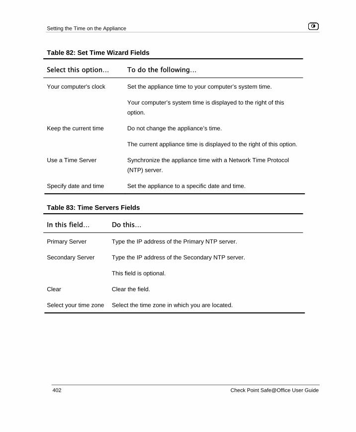
Setting the Time on the Appliance
402 Check Point Safe@Office User Guide
Table 82: Set Time Wizard Fields
Select this option… To do the following…
Your computer's clock Set the appliance time to your computer’s system time.
Your computer’s system time is displayed to the right of this
option.
Keep the current time Do not change the appliance’s time.
The current appliance time is displayed to the right of this option.
Use a Time Server Synchronize the appliance time with a Network Time Protocol
(NTP) server.
Specify date and time Set the appliance to a specific date and time.
Table 83: Time Servers Fields
In this field… Do this…
Primary Server Type the IP address of the Primary NTP server.
Secondary Server Type the IP address of the Secondary NTP server.
This field is optional.
Clear Clear the field.
Select your time zone Select the time zone in which you are located.

Using Diagnostic Tools
Chapter 14: Maintenance 403
Using Diagnostic Tools
The Safe@Office appliance is equipped with a set of diagnostic tools that are useful for troubleshooting Internet connectivity.
Table 84: Diagnostic Tools
Use this tool…
To do this… For information, see...
Ping Check that a specific IP address or DNS
name can be reached via the Internet.
Using IP Tools on page 404
Traceroute Display a list of all routers used to
connect from the Safe@Office appliance
to a specific IP address or DNS name.
Using IP Tools on page 404
WHOIS Display the name and contact information
of the entity to which a specific IP address
or DNS name is registered. This
information is useful in tracking down
hackers.
Using IP Tools on page 404
Packet Sniffer Capture network traffic. This information is
useful troubleshooting network problems. Using Packet Sniffer on page
406

Using Diagnostic Tools
404 Check Point Safe@Office User Guide
Using IP Tools
To use an IP tool
1. Click Setup in the main menu, and click the Tools tab.
The Tools page appears.
2. In the IP Tools drop-down list, select the desired tool.
3. In the Address field, type the IP address or DNS name for which to run the tool.
4. Click Go.
• If you selected Ping, the following things happen:
The Safe@Office appliance sends packets to the specified the IP address or DNS name.
The IP Tools window opens and displays the percentage of packet loss and the amount of time it each packet took to reach the specified host and return (round-trip) in milliseconds.
• If you selected Traceroute, the following things happen:
The Safe@Office appliance connects to the specified IP address or DNS name.

Using Diagnostic Tools
Chapter 14: Maintenance 405
The IP Tools window opens and displays a list of routers used to make the connection.
• If you selected WHOIS, the following things happen:
The Safe@Office appliance queries the Internet WHOIS server.
A window displays the name of the entity to which the IP address or DNS name is registered and their contact information.

Using Diagnostic Tools
406 Check Point Safe@Office User Guide
Using Packet Sniffer
The Safe@Office appliance includes the Packet Sniffer tool, which enables you to capture packets from any internal network or Safe@Office port. This is useful for troubleshooting network problems and for collecting data about network behavior.
The Safe@Office appliance saves the captured packets to a file on your computer. You can use a free protocol analyzer, such as Ethereal, to analyze the file, or you can send it to technical support. Ethereal runs on all popular computing platforms and can be downloaded from http://www.ethereal.com.
To use Packet Sniffer
1. Click Setup in the main menu, and click the Tools tab.
The Tools page appears.
2. Click Sniffer. The Packet Sniffer window opens.
3. Complete the fields using the information in the table below.
4. Click Start.

Using Diagnostic Tools
Chapter 14: Maintenance 407
The Packet Sniffer window displays the name of the interface, the number of packets collected, and the percentage of storage space remaining on the appliance for storing the packets.
5. Click Stop to stop collecting packets.
A standard File Download dialog box appears.
6. Click Save.
The Save As dialog box appears.
7. Browse to a destination directory of your choice.
8. Type a name for the configuration file and click Save.
The *.cap file is created and saved to the specified directory.
9. Click Cancel to close the Packet Sniffer window.

Using Diagnostic Tools
408 Check Point Safe@Office User Guide
Table 85: Packet Sniffer Fields
In this field… Do this…
Interface Select the interface from which to collect packets.
The list includes the primary Internet connection, the Safe@Office
appliance ports, and all defined networks.
Filter String Type the filter string to use for filtering the captured packets. Only
packets that match the filter condition will be saved.
For a list of basic filter strings elements, see Filter String Syntax on
page 409.
For detailed information on filter syntax, go to
http://www.tcpdump.org/tcpdump_man.html.
Note: Do not enclose the filter string in quotation marks.
If you do not specify a filter string, Packet Sniffer will save all packets on
the selected interface.
Capture only traffic
to/from this gateway
Select this option to capture incoming and outgoing packets for this
gateway only.
If this option is not selected, Packet Sniffer will collect packets for all
traffic on the interface.

Using Diagnostic Tools
Chapter 14: Maintenance 409
Filter String Syntax The following represents a list of basic filter string elements:
• and on page 409
• dst on page 410
• dst port on page 410
• ether proto on page 411
• host on page 412
• not on page 412
• or on page 413
• port on page 413
• src on page 414
• src port on page 414
• tcp on page 415
• udp on page 416
For detailed information on filter syntax, refer to http://www.tcpdump.org.
and PURPOSE
The and element is used to concatenate filter string elements. The filtered packets must match all concatenated filter string elements.
SYNTAX element and element [and element...]
element && element [&& element...]

Using Diagnostic Tools
410 Check Point Safe@Office User Guide
PARAMETERS
element String. A filter string element.
EXAMPLE The following filter string saves packets that both originate from IP address is 192.168.10.1 and are destined for port 80: src 192.168.10.1 and dst port 80
dst PURPOSE
The dst element captures all packets with a specific destination.
SYNTAX
dst destination
PARAMETERS
destination IP Address or String. The computer to which the packet is
sent. This can be the following:
• An IP address • A host name
EXAMPLE The following filter string saves packets that are destined for the IP address 192.168.10.1: dst 192.168.10.1
dst port PURPOSE
The dst port element captures all packets destined for a specific port.
SYNTAX dst port port

Using Diagnostic Tools
Chapter 14: Maintenance 411
Note: This element can be prepended by tcp or udp. For information, see tcp on page 415 and udp on page 416.
PARAMETERS
port Integer. The port to which the packet is sent.
EXAMPLE The following filter string saves packets that are destined for port 80: dst port 80
ether proto PURPOSE
The ether proto element is used to capture packets of a specific ether protocol type.
SYNTAX ether proto \protocol
PARAMETERS
protocol String. The protocol type of the packet.
This can be the following: ip, ip6, arp, rarp, atalk, aarp, dec net, sca, lat, mopdl, moprc, iso, stp, ipx, or
netbeui.
EXAMPLE The following filter string saves ARP packets: ether proto arp

Using Diagnostic Tools
412 Check Point Safe@Office User Guide
host PURPOSE
The host element captures all incoming and outgoing packets for a specific computer.
SYNTAX
host host
PARAMETERS
host IP Address or String. The computer to/from which the packet
is sent. This can be the following:
• An IP address • A host name
EXAMPLE The following filter string saves all packets that either originated from IP address 192.168.10.1, or are destined for that same IP address:
host 192.168.10.1
not PURPOSE
The not element is used to negate filter string elements.
SYNTAX not element
! element
PARAMETERS
element String. A filter string element.

Using Diagnostic Tools
Chapter 14: Maintenance 413
EXAMPLE The following filter string saves packets that are not destined for port 80: not dst port 80
or PURPOSE
The or element is used to alternate between string elements. The filtered packets must match at least one of the filter string elements.
SYNTAX element or element [or element...]
element || element [|| element...]
PARAMETERS
element String. A filter string element.
EXAMPLE The following filter string saves packets that either originate from IP address 192.168.10.1 or IP address 192.168.10.10: src 192.168.10.1 or src 192.168.10.10
port PURPOSE
The port element captures all packets originating from or destined for a specific port.
SYNTAX
port port
Note: This element can be prepended by tcp or udp. For information, see tcp on page 415 and udp on page 416.

Using Diagnostic Tools
414 Check Point Safe@Office User Guide
PARAMETERS
port Integer. The port from/to which the packet is sent.
EXAMPLE The following filter string saves all packets that either originated from port 80, or are destined for port 80: port 80
src PURPOSE
The src element captures all packets with a specific source.
SYNTAX
src source
PARAMETERS
source IP Address or String. The computer from which the packet is
sent. This can be the following:
• An IP address • A host name
EXAMPLE The following filter string saves packets that originated from IP address 192.168.10.1: src 192.168.10.1
src port PURPOSE
The src port element captures all packets originating from a specific port.
SYNTAX src port port

Using Diagnostic Tools
Chapter 14: Maintenance 415
Note: This element can be prepended by tcp or udp. For information, see tcp on page 415 and udp on page 416.
PARAMETERS
port Integer. The port to which the packet is sent.
EXAMPLE The following filter string saves packets that originated from port 80: src port 80
tcp PURPOSE
The tcp element captures all TCP packets. This element can be prepended to port-related elements.
Note: When not prepended to other elements, the tcp element is the equivalent of ip proto tcp.
SYNTAX tcp tcp element
PARAMETERS
element String. A port-related filter string element that should be
restricted to saving only TCP packets. This can be the
following:
• dst port - Capture all TCP packets destined for a specific port.
• port - Captures all TCP packets originating from or destined for a specific port.
• src port - Capture all TCP packets originating from a specific port.

Using Diagnostic Tools
416 Check Point Safe@Office User Guide
EXAMPLE 1 The following filter string captures all TCP packets: tcp
EXAMPLE 2 The following filter string captures all TCP packets destined for port 80: tcp dst port 80
udp PURPOSE
The udp element captures all UDP packets. This element can be prepended to port-related elements.
Note: When not prepended to other elements, the udp element is the equivalent of ip proto udp.
SYNTAX udp udp element
PARAMETERS
element String. A port-related filter string element that should be
restricted to saving only UDP packets. This can be the
following:
• dst port - Capture all UDP packets destined for a specific port.
• port - Captures all UDP packets originating from or destined for a specific port.
• src port - Capture all UDP packets originating from a specific port.
EXAMPLE 1 The following filter string captures all UDP packets:

Backing Up the Safe@Office Appliance Configuration
Chapter 14: Maintenance 417
udp
EXAMPLE 2 The following filter string captures all UDP packets destined for port 80: udp dst port 80
Backing Up the Safe@Office Appliance Configuration
You can export the Safe@Office appliance configuration to a *.cfg file, and use this file to backup and restore Safe@Office appliance settings, as needed. The file includes all your settings.
The configuration file is saved as a textual CLI script. If desired, you can edit the file. For a full explanation of the CLI script format and the supported CLI commands, see the Embedded NGX CLI Reference Guide.
Exporting the Safe@Office Appliance Configuration
Exporting the Safe@Office appliance configuration creates a configuration file.
To export the Safe@Office appliance configuration
1. Click Setup in the main menu, and click the Tools tab.
The Tools page appears.
2. Click Export. A standard File Download dialog box appears.
3. Click Save.
The Save As dialog box appears.

Backing Up the Safe@Office Appliance Configuration
418 Check Point Safe@Office User Guide
4. Browse to a destination directory of your choice.
5. Type a name for the configuration file and click Save.
The *.cfg configuration file is created and saved to the specified directory.
Importing the Safe@Office Appliance Configuration
In order to restore your Safe@Office appliance’s configuration from a configuration file, you must import the file.
To import the Safe@Office appliance configuration
1. Click Setup in the main menu, and click the Tools tab.
The Tools page appears.
2. Click Import. The Import Settings page appears.
3. Do one of the following:

Backing Up the Safe@Office Appliance Configuration
Chapter 14: Maintenance 419
• In the Import Settings field, type the full path to the configuration file. Or
• Click Browse, and browse to the configuration file. 4. Click Upload.
A confirmation message appears.
5. Click OK.
The Safe@Office appliance settings are imported.
The Import Settings page displays the configuration file's content and the result of implementing each configuration command.
Note: If the appliance's IP address changed as a result of the configuration import, your computer may be disconnected from the network; therefore you may not be able to see the results.

Resetting the Safe@Office Appliance to Defaults
420 Check Point Safe@Office User Guide
Resetting the Safe@Office Appliance to Defaults
You can reset the Safe@Office appliance to its default settings. When you reset your Safe@Office appliance, it reverts to the state it was originally in when you purchased it. You can choose to keep the current firmware or to revert to the firmware version that shipped with the Safe@Office appliance.
Warning: This operation erases all your settings and password information. You will have to set a new password and reconfigure your Safe@Office appliance for Internet connection. For information on performing these tasks, see Setting Up the Safe@Office Appliance.
You can reset the Safe@Office appliance to defaults via the Web management interface (software) or by manually pressing the Reset button (hardware) located at the back of the Safe@Office appliance.
To reset the Safe@Office appliance to factory defaults via the Web interface
1. Click Setup in the main menu, and click the Tools tab.
The Tools page appears.
2. Click Factory Settings.

Resetting the Safe@Office Appliance to Defaults
Chapter 14: Maintenance 421
A confirmation message appears.
3. To revert to the firmware version that shipped with the appliance, select the
check box.
4. Click OK.
• The Please Wait screen appears.
• The Safe@Office appliance returns to its factory defaults.
• The Safe@Office appliance is restarted (the PWR/SEC LED flashes quickly).
This may take a few minutes.
• The Login page appears.
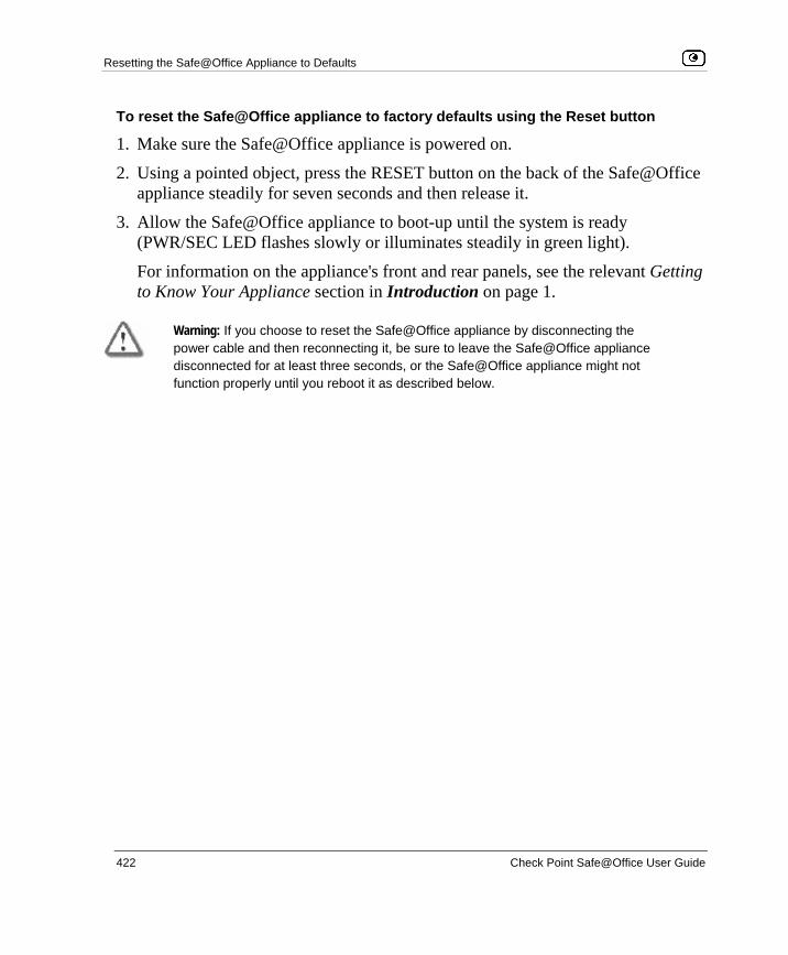
Resetting the Safe@Office Appliance to Defaults
422 Check Point Safe@Office User Guide
To reset the Safe@Office appliance to factory defaults using the Reset button
1. Make sure the Safe@Office appliance is powered on.
2. Using a pointed object, press the RESET button on the back of the Safe@Office appliance steadily for seven seconds and then release it.
3. Allow the Safe@Office appliance to boot-up until the system is ready (PWR/SEC LED flashes slowly or illuminates steadily in green light).
For information on the appliance's front and rear panels, see the relevant Getting to Know Your Appliance section in Introduction on page 1.
Warning: If you choose to reset the Safe@Office appliance by disconnecting the power cable and then reconnecting it, be sure to leave the Safe@Office appliance disconnected for at least three seconds, or the Safe@Office appliance might not function properly until you reboot it as described below.

Running Diagnostics
Chapter 14: Maintenance 423
Running Diagnostics
You can view technical information about your Safe@Office appliance’s hardware, firmware, license, network status, and Service Center.
This information is useful for troubleshooting. You can export it to an *.html file and send it to technical support.
To view diagnostic information
1. Click Setup in the main menu, and click the Tools tab.
The Tools page appears.
2. Click Diagnostics.
Technical information about your Safe@Office appliance appears in a new window.
3. To save the displayed information to an *.html file:
a. Click Save.
A standard File Download dialog box appears.
b. Click Save.
The Save As dialog box appears.
c. Browse to a destination directory of your choice.
d. Type a name for the configuration file and click Save.
The *.html file is created and saved to the specified directory. 4. To refresh the contents of the window, click Refresh.
The contents are refreshed.
5. To close the window, click Close.

Rebooting the Safe@Office Appliance
424 Check Point Safe@Office User Guide
Rebooting the Safe@Office Appliance
If your Safe@Office appliance is not functioning properly, rebooting it may solve the problem.
To reboot the Safe@Office appliance
1. Click Setup in the main menu, and click the Firmware tab.
The Firmware page appears.
2. Click Restart. A confirmation message appears.
3. Click OK.
• The Please Wait screen appears.
• The Safe@Office appliance is restarted (the PWR/SEC LED flashes
quickly).
This may take a few minutes.
• The Login page appears.

Overview
Chapter 15: Using Network Printers 425
Chapter 15
This chapter describes how to set up and use network printers.
This chapter includes the following topics: Overview ..................................................................................................425 Setting Up Network Printers.....................................................................426 Configuring Computers to Use Network Printers.....................................427 Viewing Network Printers ........................................................................437 Changing Network Printer Ports...............................................................437 Resetting Network Printers.......................................................................438
Overview The Safe@Office 500W includes a built-in print server, enabling you to connect USB-based printers to the appliance and share them across the network.
Note: When using computers with a Windows 2000/XP operating system, the Safe@Office appliance supports connecting up to four USB-based printers to the appliance. When using computers with a MAC OS-X operating system, the Safe@Office appliance supports connecting one printer.
The appliance automatically detects printers as they are plugged in, and they immediately become available for printing. Usually, no special configuration is required on the Safe@Office appliance.
Note: The Safe@Office print server supports printing via "all-in-one" printers. Copying and scanning functions are not supported.
Using Network Printers
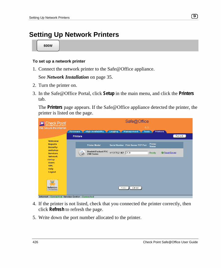
Setting Up Network Printers
426 Check Point Safe@Office User Guide
Setting Up Network Printers
To set up a network printer
1. Connect the network printer to the Safe@Office appliance.
See Network Installation on page 35.
2. Turn the printer on.
3. In the Safe@Office Portal, click Setup in the main menu, and click the Printers tab.
The Printers page appears. If the Safe@Office appliance detected the printer, the printer is listed on the page.
4. If the printer is not listed, check that you connected the printer correctly, then
click Refresh to refresh the page.
5. Write down the port number allocated to the printer.

Configuring Computers to Use Network Printers
Chapter 15: Using Network Printers 427
The port number appears in the Printer Server TCP Port field. You will need this number later, when configuring computers to use the network printer.
6. To change the port number, do the following:
a. Type the desired port number in the Printer Server TCP Port field.
Note: Printer port numbers may not overlap, and must be high ports.
b. Click Apply. You may want to change the port number if, for example, the printer you are setting up is intended to replace another printer. In this case, you should change the replacement printer's port number to the old printer's port number, and you can skip the next step.
7. Configure each computer from which you want to enable printing to the network printer.
See Configuring Computers to Use Network Printers on page 427.
Configuring Computers to Use Network Printers
Perform the relevant procedure on each computer from which you want to enable printing via the Safe@Office print server to a network printer.
Windows 2000/XP This procedure is relevant for computers with a Windows 2000/XP operating system.
To configure a computer to use a network printer 1. If the computer for which you want to enable printing is located on the WAN,
create an Allow rule for connections from the computer to This Gateway.
See Adding and Editing Rules on page 213.

Configuring Computers to Use Network Printers
428 Check Point Safe@Office User Guide
2. Click Start > Settings > Control Panel. The Control Panel window opens.
3. Click Printers and Faxes.
The Printers and Faxes window opens.
4. Right-click in the window, and click Add Printer in the popup menu.
The Add Printer Wizard opens with the Welcome dialog box displayed.
5. Click Next.
The Local or Network Printer dialog box appears.
6. Click Local printer attached to this computer.

Configuring Computers to Use Network Printers
Chapter 15: Using Network Printers 429
Note: Do not select the Automatically detect and install my Plug and Play printer check box.
7. Click Next. The Select a Printer Port dialog box appears.
8. Click Create a new port. 9. In the Type of port drop-down list, select Standard TCP/IP Port. 10. Click Next.
The Add Standard TCP/IP Port Wizard opens with the Welcome dialog box displayed.
11. Click Next.

Configuring Computers to Use Network Printers
430 Check Point Safe@Office User Guide
The Add Port dialog box appears.
12. In the Printer Name or IP Address field, type the Safe@Office appliance's
LAN IP address, or "my.firewall".
You can find the LAN IP address in the Safe@Office Portal, under Network > My Network.
The Port Name field is filled in automatically.
13. Click Next. The Add Standard TCP/IP Printer Port Wizard opens, with the Additional Port Information Required dialog box displayed.
14. Click Custom.
15. Click Settings.
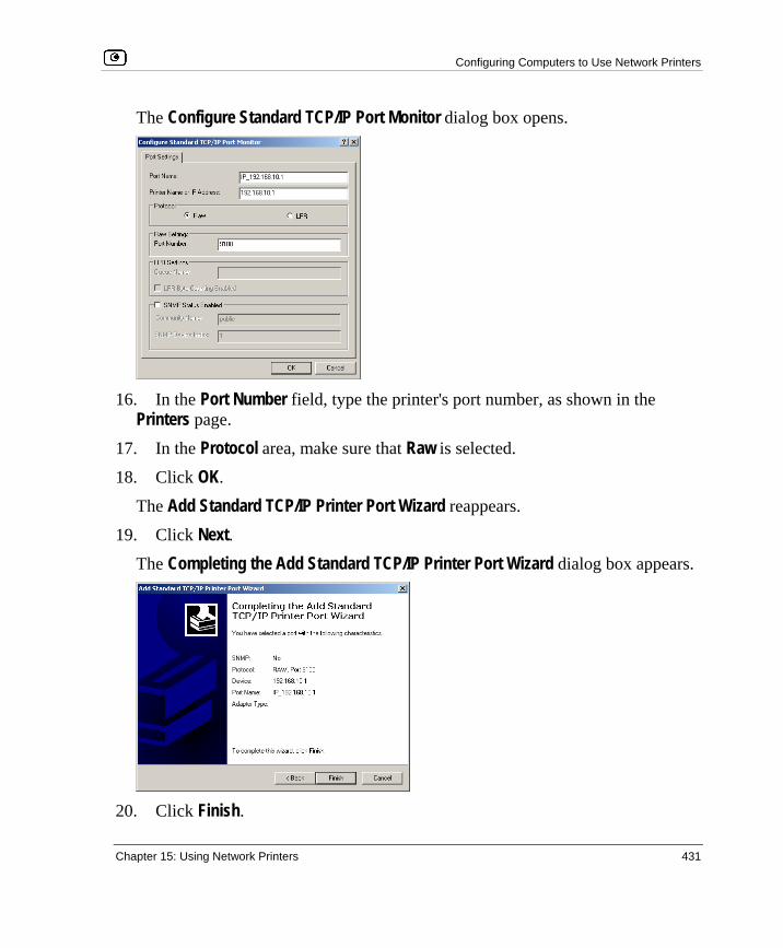
Configuring Computers to Use Network Printers
Chapter 15: Using Network Printers 431
The Configure Standard TCP/IP Port Monitor dialog box opens.
16. In the Port Number field, type the printer's port number, as shown in the
Printers page.
17. In the Protocol area, make sure that Raw is selected.
18. Click OK.
The Add Standard TCP/IP Printer Port Wizard reappears.
19. Click Next. The Completing the Add Standard TCP/IP Printer Port Wizard dialog box appears.
20. Click Finish.

Configuring Computers to Use Network Printers
432 Check Point Safe@Office User Guide
The Add Printer Wizard reappears, with the Install Printer Software dialog box displayed.
21. Do one of the following:
• Use the lists to select the printer's manufacturer and model.
• If your printer does not appear in the lists, insert the CD that came with your printer in the computer's CD-ROM drive, and click Have Disk.
22. Click Next. 23. Complete the remaining dialog boxes in the wizard as desired, and click
Finish.
The printer appears in the Printers and Faxes window.
24. Right-click the printer and click Properties in the popup menu.
The printer's Properties dialog box opens.
25. In the Ports tab, in the list box, select the port you added.

Configuring Computers to Use Network Printers
Chapter 15: Using Network Printers 433
The port's name is IP_<LAN IP address>.
26. Click OK.
MAC OS-X This procedure is relevant for computers with the latest version of the MAC OS-X operating system.
Note: This procedure may not apply to earlier MAC OS-X versions.
To configure a computer to use a network printer 1. If the computer for which you want to enable printing is located on the WAN,
create an Allow rule for connections from the computer to This Gateway.
See Adding and Editing Rules on page 213.
2. Choose Apple -> System Preferences.

Configuring Computers to Use Network Printers
434 Check Point Safe@Office User Guide
The System Preferences window appears.
3. Click Show All to display all categories.
4. In the Hardware area, click Print & Fax.
The Print & Fax window appears.
5. In the Printing tab, click Set Up Printers.

Configuring Computers to Use Network Printers
Chapter 15: Using Network Printers 435
The Printer List window appears.
6. Click Add.
New fields appear.
7. In the first drop-down list, select IP Printing.
8. In the Printer Type drop-down list, select Socket/HP Jet Direct. 9. In the Printer Address field, type the Safe@Office appliance's LAN IP address,
or "my.firewall".
You can find the LAN IP address in the Safe@Office Portal, under Network > My Network.
10. In the Queue Name field, type the name of the required printer queue.
For example, the printer queue name for HP printers is RAW.

Configuring Computers to Use Network Printers
436 Check Point Safe@Office User Guide
11. In the Printer Model list, select the desired printer type.
A list of models appears.
12. In the Model Name list, select the desired model.
13. Click Add.
The new printer appears in the Printer List window.
14. In the Printer List window, select the newly added printer, and click Make
Default.

Viewing Network Printers
Chapter 15: Using Network Printers 437
Viewing Network Printers
To view network printers
1. Click Setup in the main menu, and click the Printers tab.
The Printers page appears, displaying a list of connected printers.
For each printer, the model, serial number, port, and status is displayed.
A printer can have the following statuses:
• Initialize. The printer is initializing. • Ready. The printer is ready. • Not Ready. The printer is not ready. For example, it may be out of paper.
• Printing. The printer is processing a print job.
• Restarting. The printer server is restarting.
• Fail. An error occurred. See the Event Log for details (Viewing the Event Log on page 187).
2. To refresh the display, click Refresh.
Changing Network Printer Ports
When you set up a new network printer, the Safe@Office appliance automatically assigns a port number to the printer. If you want to use a different port number, you can easily change it, as described in Setting up Network Printers on page 426.
However, you may sometimes need to change the port number after completing printer setup. For example, you may want to replace a malfunctioning network printer, with another existing network printer, without reconfiguring the client

Resetting Network Printers
438 Check Point Safe@Office User Guide
computers. To do this, you must change the replacement printer's port number to the malfunctioning printer's port number, as described below.
Note: Each printer port number must be different, and must be a high port.
To change a printer's port
1. Click Setup in the main menu, and click the Printers tab.
The Printers page appears.
2. In the printer's Printer Server TCP Port field, type the desired port number.
3. Click Apply.
Resetting Network Printers
Resetting Network Printers
Chapter 16: Troubleshooting 439
Chapter 16
This chapter provides solutions to common problems you may encounter while using the Safe@Office appliance.
Note: For information on troubleshooting wireless connectivity, see Troubleshooting Wireless Connectivity on page 183.
This chapter includes the following topics: Connectivity ............................................................................................ 440 Service Center and Upgrades................................................................... 444 Other Problems ........................................................................................ 445
Troubleshooting

Connectivity
440 Check Point Safe@Office User Guide
Connectivity I cannot access the Internet. What should I do? • Check if the PWR/SEC LED is green. If not, check the power connection
to the Safe@Office appliance.
• Check if the WAN LINK/ACT LED is green. If not, check the network cable to the modem and make sure the modem is turned on.
• Check if the LAN LINK/ACT LED for the port used by your computer is green. If not, check if the network cable linking your computer to the Safe@Office appliance is connected properly. Try replacing the cable or connecting it to a different LAN port.
• Using your Web browser, go to http://my.firewall and see whether "Connected" appears on the Status Bar. Make sure that your Safe@Office appliance network settings are configured as per your ISP directions.
• Check your TCP/IP configuration according to Installing and Setting up the Safe@Office Appliance on page 15.
• If Web Filtering or Email Filtering are on, try turning them off.
• Check if you have defined firewall rules which block your Internet connectivity.
• Check with your ISP for possible service outage.
• Check whether you are exceeding the maximum number of computers allowed by your license, by viewing the Active Computers page.
I cannot access my DSL broadband connection. What should I do? DSL equipment comes in two flavors: bridges (commonly known as DSL modems) and routers. Some DSL equipment can be configured to work both ways.

Connectivity
Chapter 16: Troubleshooting 441
• If you connect to your ISP using a PPPoE or PPTP dialer defined in your operating system, your equipment is most likely configured as a DSL bridge. Configure a PPPoE or PPTP type DSL connection.
• If you were not instructed to configure a dialer in your operating system, your equipment is most likely configured as a DSL router. Configure a LAN connection, even if you are using a DSL connection.
For instructions, see Configuring the Internet Connection on page 53.
I cannot access my Cable broadband connection. What should I do? • Some cable ISPs require you to register the MAC address of the device
behind the cable modem. You may need to clone your Ethernet adapter MAC address onto the Safe@Office appliance. For instructions, see Configuring the Internet Connection on page 53.
• Some cable ISPs require using a hostname for the connection. Try reconfiguring your Internet connection and specifying a hostname. For further information, see Configuring the Internet Connection on page 53.
I cannot access http://my.firewall or http://my.vpn. What should I do? • Verify that the Safe@Office appliance is operating (PWR/SEC LED is
active)
• Check if the LAN LINK/ACT LED for the port used by your computer is on. If not, check if the network cable linking your computer to the Safe@Office appliance is connected properly.
Note: You may need to use a crossed cable when connecting the Safe@Office appliance to another hub/switch.
• Try surfing to 192.168.10.1 instead of to my.firewall.
Note: 192.168.10 is the default value, and it may vary if you changed it in the My Network page.

Connectivity
442 Check Point Safe@Office User Guide
• Check your TCP/IP configuration according to Installing and Setting up the Safe@Office Appliance on page 15.
• Restart your Safe@Office appliance and your broadband modem by disconnecting the power and reconnecting after 5 seconds.
• If your Web browser is configured to use an HTTP proxy to access the Internet, add "my.firewall" or "my.vpn" to your proxy exceptions list.
My network seems extremely slow. What should I do? • The Ethernet cables may be faulty. For proper operation, the Safe@Office
appliance requires STP CAT5 (Shielded Twisted Pair Category 5) Ethernet cables. Make sure that this specification is printed on your cables.
• Your Ethernet card may be faulty or incorrectly configured. Try replacing your Ethernet card.
• There may be an IP address conflict in your network. Check that the TCP/IP settings of all your computers are configured to obtain an IP address automatically.
I changed the network settings to incorrect values and am unable to correct my error. What should I do?
Reset the network to its default settings using the button on the back of the Safe@Office appliance unit. See Resetting the Safe@Office Appliance to Defaults on page 420.
I am using the Safe@Office appliance behind another NAT device, and I am having problems with some applications. What should I do?
By default, the Safe@Office appliance performs Network Address Translation (NAT). It is possible to use the Safe@Office appliance behind another device that performs NAT, such as a DSL router or Wireless router, but the device will block all incoming connections from reaching your Safe@Office appliance.
To fix this problem, do ONE of the following. (The solutions are listed in order of preference.)

Connectivity
Chapter 16: Troubleshooting 443
• Consider whether you really need the router. The Safe@Office appliance can be used as a replacement for your router, unless you need it for some additional functionality that it provides, such as Wireless access.
• If possible, disable NAT in the router. Refer to the router’s documentation for instructions on how to do this.
• If the router has a “DMZ Computer” or “Exposed Host” option, set it to the Safe@Office appliance’s external IP address.
• Open the following ports in the NAT device:
• UDP 9281/9282
• UDP 500
• TCP 256
• TCP 264
• ESP IP protocol 50
• TCP 981
I cannot receive audio or video calls through the Safe@Office appliance. What should I do? To enable audio/video, you must configure an IP Telephony (H.323) virtual server. For instructions, see Configuring Servers on page 207.
I run a public Web server at home but it cannot be accessed from the Internet. What should I do?
Configure a virtual Web Server. For instructions, see Configuring Servers on page 207.
I cannot connect to the LAN network from the DMZ or WLAN network. What should I do? By default, connections from the DMZ or WLAN network to the LAN network are blocked. To allow traffic from the DMZ or WLAN to the LAN, configure appropriate firewall rules. For instructions, see Using Rules on page 209.
Service Center and Upgrades
444 Check Point Safe@Office User Guide
Service Center and Upgrades I purchased an advanced Safe@Office model, but I only have the functionality of a simpler Safe@Office model. What should I do?
Your have not installed your product key. For further information, see Upgrading Your Software Product on page 381.
I have exceeded my node limit. What does this mean? What should I do? Your Product Key specifies a maximum number of nodes that you may connect to the Safe@Office appliance.
The Safe@Office appliance tracks the cumulative number of nodes on the internal network that have communicated through the firewall. When the Safe@Office appliance encounters an IP address that exceeds the licensed node limit, the Active Computers page displays a warning message and marks nodes over the node limit in red. These nodes will not be able to access the Internet through the Safe@Office appliance, but will be protected. The Event Log page also warns you that you have exceeded the node limit.
To upgrade your Safe@Office appliance to support more nodes, purchase a new Product Key. Contact your reseller for upgrade information.
While trying to connect to a Service Center, I received the message “The Service Center did not respond”. What should I do? • If you are using a Service Center other than the Check Point Service
Center, check that the Service Center IP address is typed correctly.
• The Safe@Office appliance connects to the Service Center using UDP ports 9281/9282. If the Safe@Office appliance is installed behind another firewall, make sure that these ports are open.

Other Problems
Chapter 16: Troubleshooting 445
Other Problems I have forgotten my password. What should I do?
Reset your Safe@Office appliance to factory defaults using the Reset button as detailed in Resetting the Safe@Office Appliance to Defaults on page 420.
Why are the date and time displayed incorrectly? You can adjust the time on the Setup page's Tools tab. For information, see Setting the Time on the Appliance on page 399.
I cannot use a certain network application. What should I do? Look at the Event Log page. If it lists blocked attacks, do the following:
• Set the Safe@Office appliance's firewall level to Low and try again.
• If the application still does not work, set the computer on which you want to use the application to be the exposed host.
For instructions, see Defining an Exposed Host on page 261.
When you have finished using the application, make sure to clear the exposed host setting, otherwise your security might be compromised.

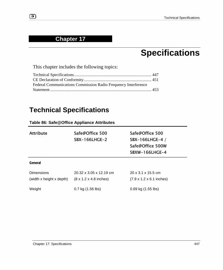
Technical Specifications
Chapter 17: Specifications 447
Chapter 17
This chapter includes the following topics: Technical Specifications.......................................................................... 447 CE Declaration of Conformity................................................................. 451 Federal Communications Commission Radio Frequency Interference Statement ................................................................................................. 453
Technical Specifications Table 86: Safe@Office Appliance Attributes
Attribute Safe@Office 500 SBX-166LHGE-2
Safe@Office 500 SBX-166LHGE-4 / Safe@Office 500W SBXW-166LHGE-4
General
Dimensions
(width x height x depth)
20.32 x 3.05 x 12.19 cm
(8 x 1.2 x 4.8 inches)
20 x 3.1 x 15.5 cm
(7.9 x 1.2 x 6.1 inches)
Weight 0.7 kg (1.56 lbs) 0.69 kg (1.55 lbs)
Specifications

Technical Specifications
448 Check Point Safe@Office User Guide
Attribute Safe@Office 500 SBX-166LHGE-2
Safe@Office 500 SBX-166LHGE-4 / Safe@Office 500W SBXW-166LHGE-4
Power supply nominal
input voltage, frequency
US Model: 90~132 VAC,
50~60Hz
Japan Model: 100VAC,
50~60Hz
EU Model: 200~265 VAC,
50~60Hz
All Models: 100~240VAC,
50~60Hz
Power supply nominal
output voltage
All Models: 9VAC, 1.5A All Models: 5VDC, 3A
Max. Power
Consumption
7.5W 8W (1.6A w/o external USB
devices)
13W (2.6A w USB devices)
Retail box dimensions
(width x height x depth)
31 x 10 x 16 cm
(12.4 x 4 x 6.4 inches)
29 x 25 x 7.6 cm
(11.4 x 9.8 x 3 inches)
Retail box weight 1.3 kg (2.9 lbs) 1.35 kg (3 lbs)
Environmental
Conditions
Temperature:
Storage/Transport
- 20°C to +70°C - 5°C to +70°C
Temperature: Operation + 5°C to +45°C - 5°C ~ 50°C
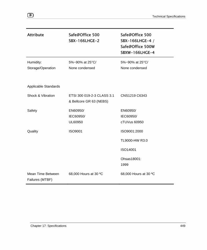
Technical Specifications
Chapter 17: Specifications 449
Attribute Safe@Office 500 SBX-166LHGE-2
Safe@Office 500 SBX-166LHGE-4 / Safe@Office 500W SBXW-166LHGE-4
Humidity:
Storage/Operation
5%~90% at 25°C/
None condensed
5%~90% at 25°C/
None condensed
Applicable Standards
Shock & Vibration ETSI 300 019-2-3 CLASS 3.1
& Bellcore GR 63 (NEBS)
CNS1219 C6343
Safety EN60950/
IEC60950/
UL60950
EN60950/
IEC60950/
cTUVus 60950
Quality ISO9001 ISO9001:2000
TL9000-HW R3.0
ISO14001
Ohsas18001:
1999
Mean Time Between
Failures (MTBF)
68,000 Hours at 30 ºC 68,000 Hours at 30 ºC

Technical Specifications
450 Check Point Safe@Office User Guide
Table 87: Safe@Office Wireless Attributes
Attribute Safe@Office 500W series
Operation Frequency 2.412-2.484 MHz
Transmission Power 79.4 mW
Modulation OFDM, DSSS, 64QAM, 16QAM, QPSK, BPSK, CCK, DQPSK,
DBPSK
WPA Authentication
Modes
EAP-TLS, EAP-TTLS, PEAP (EAP-GTC), PEAP (EAP-MSCHAP
V2)

CE Declaration of Conformity
Chapter 17: Specifications 451
CE Declaration of Conformity SofaWare Technologies Ltd., 3 Hilazon St., Ramat-Gan Israel, hereby declares that this equipment is in conformity with the essential requirements specified in Article 3.1 (a) and 3.1 (b) of:
• Directive 89/336/EEC (EMC Directive)
• Directive 73/23/EEC (Low Voltage Directive – LVD)
• Directive 99/05/EEC (Radio Equipment and Telecommunications Terminal Equipment Directive)
In accordance with the following standards:
Table 88: Safe@Office Appliance Standards
Attribute Safe@Office 500 SBX-166LHGE-2
Safe@Office 500 SBX-166LHGE-4 / Safe@Office 500W SBXW-166LHGE-4
EMC EN 55022:1998
EN 61000-3-2: 1995
EN 61000-3-3: 1995
EN 61000-4-2:1995
EN 61000-4-3:1995
EN 61000-4-4:1995
EN 61000-4-5:1995
EN 61000-4-6:1996
EN 50081-1:1992
EN 50082-1:1997
EN 61000-6-1:2001
EN 61000-6-3:2001
EN 55022:1998
EN 55024:1998
EN 61000-3-2: 1995
EN 61000-3-3: 1995

CE Declaration of Conformity
452 Check Point Safe@Office User Guide
Attribute Safe@Office 500 SBX-166LHGE-2
Safe@Office 500 SBX-166LHGE-4 / Safe@Office 500W SBXW-166LHGE-4
EN 61000-4-8:1993
EN 61000-4-11:1994
ENV50204:1995
EN 61000-4-2:1995
EN 61000-4-3:1996/A2:2001
EN 61000-4-4:1995
EN 61000-4-5:1995
EN 61000-4-6:1996
EN 61000-4-7:1993
EN 61000-4-8:1993
EN 61000-4-9:1993
EN 61000-4-10:1993
EN 61000-4-11:1994
EN 61000-4-12:1995
Safety EN 60950: 2000
IEC 60950:1999
EN 60950: 2000
IEC 60950:1999
The "CE" mark is affixed to this product to demonstrate conformance to the R&TTE Directive 99/05/EEC (Radio Equipment and Telecommunications Terminal Equipment Directive) and FCC Part 15 Class B.
The product has been tested in a typical configuration. For a copy of the Original Signed Declaration (in full conformance with EN45014), please contact SofaWare at the above address.

Federal Communications Commission Radio Frequency Interference Statement
Chapter 17: Specifications 453
Federal Communications Commission Radio Frequency Interference Statement
This equipment complies with the limits for a Class B digital device, pursuant to Part 15 of the FCC Rules. These limits are designed to provide reasonable protection against harmful interference when the equipment is operated in a commercial environment. This equipment generates, uses, and can radiate radio frequency energy and, if not installed and used in accordance with the instruction manual, may cause harmful interference to radio communications.
Shielded cables must be used with this equipment to maintain compliance with FCC regulations.
Any changes or modifications to this product not explicitly approved by the manufacturer could void the user’s authority to operate the equipment and any assurances of Safety or Performance, and could result in violation of Part 15 of the FCC Rules.
This device complies with Part 15 of the FCC Rules. Operation is subject to the following two conditions: (1) this device may not cause harmful interference, and (2) this device must accept any interference received, including interference that may cause undesired operation.
This Class B digital apparatus complies with Canadian ICES-003.
FCC Radiation Exposure Statement for Wireless Models This equipment complies with FCC radiation exposure limits set forth for an uncontrolled environment. The antenna(s) used for this equipment must be installed to provide a separation distance of at least eight inches (20 cm) from all persons. This equipment must not be operated in conjunction with any other antenna.


Glossary of Terms
Glossary of Terms 455
A ADSL Modem
A device connecting a computer to the Internet via an existing phone line. ADSL (Asymmetric Digital Subscriber Line) modems offer a high-speed 'always-on' connection.
C CA
The Certificate Authority (CA) issues certificates to entities such as gateways, users, or computers. The entity later uses the certificate to identify itself and provide verifiable information. For instance, the certificate includes the Distinguished Name (DN) (identifying information) of the entity, as well as the public key (information about itself), and possibly the IP address.
After two entities exchange and validate each other's certificates, they can begin encrypting information between themselves using the public keys in the certificates.
Cable Modem A device connecting a computer to the Internet via the cable television
network. Cable modems offer a high-speed 'always-on' connection.
Certificate Authority The Certificate Authority (CA) issues certificates to entities such as gateways, users, or computers. The entity later uses the certificate to identify itself and provide verifiable information. For instance, the certificate includes the Distinguished Name (DN) (identifying information) of the entity, as well as the public key (information about itself), and possibly the IP address.
After two entities exchange and validate each other's certificates, they can begin encrypting information between themselves using the public keys in the certificates.
Cracking An activity in which someone breaks into someone else's computer system, bypasses passwords or licenses in computer programs; or in other ways intentionally breaches computer security. The end result is that whatever resides on the computer can be viewed and sensitive data can be stolen without
Glossary of Terms

Glossary of Terms
456 Check Point Safe@Office User Guide
anyone knowing about it. Sometimes, tiny programs are 'planted' on the computer that are designed to watch out for, seize and then transmit to another computer, specific types of data.
D DHCP
Any machine requires a unique IP address to connect to the Internet using Internet Protocol. Dynamic Host Configuration Protocol (DHCP) is a communications protocol that assigns Internet Protocol (IP) addresses to computers on the network.
DHCP uses the concept of a "lease" or amount of time that a given IP address will be valid for a computer.
DMZ A DMZ (demilitarized zone) is an internal network defined in addition to the LAN network and protected by the Safe@Office appliance.
DNS The Domain Name System (DNS) refers to the Internet domain names, or easy-to-remember "handles", that are translated into IP addresses.
An example of a Domain Name is 'www.sofaware.com'.
Domain Name System Domain Name System. The Domain Name System (DNS) refers to the Internet domain names, or easy-to-remember "handles", that are translated into IP addresses.
An example of a Domain Name is 'www.sofaware.com'.
E Exposed Host
An exposed host allows one computer to be exposed to the Internet. An example of using an exposed host would be exposing a public server, while preventing outside users from getting direct access form this server back to the private network.
F Firmware
Software embedded in a device.
G Gateway
A network point that acts as an entrance to another network.
H Hacking
An activity in which someone breaks into someone else's computer system, bypasses passwords or licenses in computer programs; or in

Glossary of Terms
Glossary of Terms 457
other ways intentionally breaches computer security. The end result is that whatever resides on the computer can be viewed and sensitive data can be stolen without anyone knowing about it. Sometimes, tiny programs are 'planted' on the computer that are designed to watch out for, seize and then transmit to another computer, specific types of data.
HTTPS Hypertext Transfer Protocol over Secure Socket Layer, or HTTP over SSL.
A protocol for accessing a secure Web server. It uses SSL as a sublayer under the regular HTTP application. This directs messages to a secure port number rather than the default Web port number, and uses a public key to encrypt data
HTTPS is used to transfer confidential user information.
Hub A device with multiple ports, connecting several PCs or network devices on a network.
I IP Address
An IP address is a 32-bit number that identifies each computer sending or
receiving data packets across the Internet. When you request an HTML page or send e-mail, the Internet Protocol part of TCP/IP includes your IP address in the message and sends it to the IP address that is obtained by looking up the domain name in the Uniform Resource Locator you requested or in the e-mail address you're sending a note to. At the other end, the recipient can see the IP address of the Web page requestor or the e-mail sender and can respond by sending another message using the IP address it received.
IP Spoofing A technique where an attacker attempts to gain unauthorized access through a false source address to make it appear as though communications have originated in a part of the network with higher access privileges. For example, a packet originating on the Internet may be masquerading as a local packet with the source IP address of an internal host. The firewall can protect against IP spoofing attacks by limiting network access based on the gateway interface from which data is being received.
Glossary of Terms
458 Check Point Safe@Office User Guide
IPSEC IPSEC is the leading Virtual Private Networking (VPN) standard. IPSEC enables individuals or offices to establish secure communication channels ('tunnels') over the Internet.
ISP An ISP (Internet service provider) is a company that provides access to the Internet and other related services.
L LAN
A local area network (LAN) is a group of computers and associated devices that share a common communications line and typically share the resources of a single server within a small geographic area.
M MAC Address
The MAC (Media Access Control) address is a computer's unique hardware number. When connected to the Internet from your computer, a mapping relates your IP address to your computer's physical (MAC) address on the LAN.
Mbps Megabits per second. Measurement unit for the rate of data transmission.
MTU The Maximum Transmission Unit (MTU) is a parameter that determines the largest datagram than can be transmitted by an IP interface (without it needing to be broken down into smaller units). The MTU should be larger than the largest datagram you wish to transmit un-fragmented. Note: This only prevents fragmentation locally. Some other link in the path may have a smaller MTU - the datagram will be fragmented at that point. Typical values are 1500 bytes for an Ethernet interface or 1452 for a PPP interface.
N NAT
Network Address Translation (NAT) is the translation or mapping of an IP address to a different IP address. NAT can be used to map several internal IP addresses to a single IP address, thereby sharing a single IP address assigned by the ISP among several PCs.
Check Point FireWall-1's Stateful Inspection Network Address Translation (NAT) implementation supports hundreds of pre-defined applications, services, and protocols, more than any other firewall vendor.

Glossary of Terms
Glossary of Terms 459
NetBIOS NetBIOS is the networking protocol used by DOS and Windows machines.
P Packet
A packet is the basic unit of data that flows from one source on the Internet to another destination on the Internet. When any file (e-mail message, HTML file, GIF file etc.) is sent from one place to another on the Internet, the file is divided into "chunks" of an efficient size for routing. Each of these packets is separately numbered and includes the Internet address of the destination. The individual packets for a given file may travel different routes through the Internet. When they have all arrived, they are reassembled into the original file at the receiving end.
PPPoE PPPoE (Point-to-Point Protocol over Ethernet) enables connecting multiple computer users on an Ethernet local area network to a remote site or ISP, through common customer premises equipment (e.g. modem).
PPTP The Point-to-Point Tunneling Protocol (PPTP) allows extending a local network by establishing private “tunnels” over the Internet. This protocol it is also used by some DSL providers as an alternative for PPPoE.
R RJ-45
The RJ-45 is a connector for digital transmission over ordinary phone wire.
Router A router is a device that determines the next network point to which a packet should be forwarded toward its destination. The router is connected to at least two networks.
S Server
A server is a program (or host) that awaits and requests from client programs across the network. For example, a Web server is the computer program, running on a specific host, that serves requested HTML pages or files. Your browser is the client program, in this case.
Stateful Inspection Stateful Inspection was invented by Check Point to provide the highest

Glossary of Terms
460 Check Point Safe@Office User Guide
level of security by examining every layer within a packet, unlike other systems of inspection. Stateful Inspection extracts information required for security decisions from all application layers and retains this information in dynamic state tables for evaluating subsequent connection attempts. In other words, it learns!
Subnet Mask A 32-bit identifier indicating how the network is split into subnets. The subnet mask indicates which part of the IP address is the host ID and which indicates the subnet.
T TCP
TCP (Transmission Control Protocol) is a set of rules (protocol) used along with the Internet Protocol (IP) to send data in the form of message units between computers over the Internet. While IP takes care of handling the actual delivery of the data, TCP takes care of keeping track of the individual units of data (called packets) that a message is divided into for efficient routing through the Internet.
For example, when an HTML file is sent to you from a Web server, the Transmission Control Protocol (TCP) program layer in that server
divides the file into one or more packets, numbers the packets, and then forwards them individually to the IP program layer. Although each packet has the same destination IP address, it may get routed differently through the network.
At the other end (the client program in your computer), TCP reassembles the individual packets and waits until they have arrived to forward them to you as a single file.
TCP/IP TCP/IP (Transmission Control Protocol/Internet Protocol) is the underlying communication protocol of the Internet.
U UDP
UDP (User Datagram Protocol) is a communications protocol that offers a limited amount of service when messages are exchanged between computers in a network that uses the Internet Protocol (IP). UDP is an alternative to the Transmission Control Protocol (TCP) and, together with IP, is sometimes referred to as UDP/IP. Like the Transmission Control Protocol, UDP uses the Internet Protocol to actually get a data unit (called a datagram) from one computer to another. Unlike

Glossary of Terms
Glossary of Terms 461
TCP, however, UDP does not provide the service of dividing a message into packets (datagrams) and reassembling it at the other end.
UDP is often used for applications such as streaming data.
URL A URL (Uniform Resource Locator) is the address of a file (resource) accessible on the Internet. The type of resource depends on the Internet application protocol. On the Web (which uses the Hypertext Transfer Protocol), an example of a URL is 'http://www.sofaware.com'.
V VPN
A virtual private network (VPN) is a private data network that makes use of the public telecommunication infrastructure, maintaining privacy through the use of a tunneling protocol and security procedures.
VPN tunnel A secure connection between a Remote Access VPN Client and a Remote Access VPN Server.
W WLAN
A WLAN is a wireless local area network protected by the Safe@Office appliance.


Index
Index 463
8 802.1x • 161, 163
A account, configuring • 288
active computers, viewing • 194
active connections, viewing • 197
Allow and Forward rules, explained • 213
Allow rules, explained • 213
Automatic login • 344
B backup connection
configuring • 90
dialup • 92
LAN or broadband • 91
Block Known Ports • 246
Block Port Overflow • 247
Block rules, explained • 213
Blocked FTP Commands • 248
C CA, explained • 348, 455
cable modem
connection • 58, 67
explained • 455
cable type • 35
certificate
explained • 348
generating self-signed • 349
importing • 353
installing • 348
uninstalling • 355
Cisco IOS DOS • 236
command line interface
controlling the appliance via • 388
D DHCP
configuring • 94
explained • 456
options • 101
DHCP Server
enabling/disabling • 94
explained • 94
diagnostic tools
Packet Sniffer • 406
Ping • 403
Traceroute • 403
using • 403
WHOIS • 403
Index

Index
464 Check Point Safe@Office User Guide
diagnostics • 423
dialup
connection • 75, 92
modem • 84
dialup modem, setting up • 84
DMZ
configuring • 108
configuring High Availability for • 119
explained • 108, 456
DNS • 90, 403, 456
Dynamic DNS • 5, 287
E Email Antispam, see Email Filtering • 294
Email Antivirus, see Email Filtering • 294
Email Filtering
Email Antispam • 294
Email Antivirus • 294
enabling/disabling • 295
selecting protocols for • 296
snoozing • 296
temporarily disabling • 296
event log, viewing • 187
exposed host
defining a computer as • 261
explained • 261, 456
F File and Print Sharing • 249
firewall
levels • 204
rule types • 211
setting security level • 204
firmware
explained • 377, 456
updating manually • 379
viewing status • 377
FTP Bounce • 245
G gateways
backup • 119
default • 108, 119, 139
explained • 456
ID • 287
master • 119
Site-to-Site VPN • 301
H Hide NAT
enabling/disabling • 107
explained • 107, 458
high availability
configuring • 119
explained • 119

Index
Index 465
Host Port Scan • 242
HTTPS
configuring • 392
explained • 457
using • 44
hub • 35, 90, 119, 440, 457
I IGMP • 251
IKE traces, viewing • 359
initial login • 39
installation
cable type • 35
network • 35
Instant Messengers • 254
internal VPN Server
configuring • 310
explained • 306
Internet connection
configuring • 53
configuring backup • 90
enabling/disabling • 88
establishing quick • 88
terminating • 90
troubleshooting • 440
viewing information • 87
Internet Setup • 63
Internet Wizard • 54
IP address
changing • 105
explained • 457
hiding • 107
IP Fragments • 232
IPSEC
VPN mode • 457
ISP, explained • 458
L LAN
cable • 35
configuring High Availability for • 119
connection • 54, 56, 65
explained • 458
ports • 35
LAND • 226
licenses • 194, 377, 423, 440
upgrading • 381
link configurations, modifying • 149
logs
exporting • 187
viewing • 187
M MAC address • 458
Manual Login • 344
Max Ping Size • 231

Index
466 Check Point Safe@Office User Guide
MTU, explained • 77, 458
N NetBIOS, explained • 458
network
changing internal range of • 105
configuring • 93
configuring a DMZ • 108
configuring a VLAN • 111
configuring a WLAN • 161
configuring DHCP options • 101
configuring high availability • 119
configuring the OfficeMode network • 110
enabling DHCP Server on • 94
enabling Hide NAT • 107
installation on • 35
managing • 93
objects • 129
network objects
adding and editing • 130
using • 129
viewing and deleting • 138
Network Quota • 234
node limit, viewing • 194
Non-TCP Flooding • 227
Null Payload • 238
O OfficeMode
about • 110
configuring • 110
P packet • 87, 139, 403, 457, 459
Packet Sanity • 229
Packet Sniffer
filter string syntax • 409
using • 406
Pass rules, explained • 268
password
changing • 361
setting up • 39
Peer to Peer • 252
Ping • 403
Ping of Death • 225
Port-based VLAN
about • 111
adding and editing • 114
ports
managing • 145
modifying assignments • 147
modifying link configurations • 149
resetting to defaults • 150
viewing statuses • 146
PPTP

Index
Index 467
connection • 61, 71
explained • 459
print server • 425
printers
changing ports • 437
configuring computers to use • 427
resetting • 438
setting up • 426
using • 425
viewing • 437
Q QoS
classes • 151
explained • 151
QoS classes
adding and editing • 155
assigning services to • 209
built-in • 154, 160
deleting • 159
explained • 151
restoring defaults • 160
R RADIUS
configuring VSA • 374
explained • 370
using • 370
rebooting • 424
registering • 385
Remote Access VPN Clients, explained • 301
Remote Access VPN Servers
configuring • 307, 309
explained • 301
Remote Access VPN sites • 314
reports
active computers • 194
active connections • 197
event log • 187
node limit • 194
traffic • 191
viewing • 187
wireless statistics • 198
routers • 90, 119, 403, 440, 459
rules
security • 209
VStream Antivirus • 267
S Safe@Office series
rear panel • 11
Safe@Office 500
front panel • 10
rear panel • 8
Safe@Office 500 series

Index
468 Check Point Safe@Office User Guide
about • 1
features • 2
product family • 2
Safe@Office 500W
front panel • 13
rear panel • 11
Safe@Office appliance
backing up • 417
changing internal IP address of • 105
configuring Internet connection • 53
exporting configuration • 417
importing configuration • 418
installing • 15, 35
maintenance • 377
mounting • 30
rebooting • 424
registering • 385
resetting to factory defaults • 420
setting the time • 399
setting up • 36
Safe@Office Portal
elements • 46
initial login • 39
logging on • 42
remotely accessing • 44
using • 46
Scan rules, explained • 268
Secure HotSpot
customizing • 259
enabling/disabling • 258
quick guest users • 367
setting up • 257
using • 256
SecuRemote
explained • 306
installing • 311
security
configuring servers • 207
creating rules • 209
defining a computer as an exposed host • 261
firewall • 204
Secure HotSpot • 256
SmartDefense • 220
security policy
default • 203
setting up • 203
security rules
adding and editing • 213
changing priority • 219
deleting • 219
enabling/disabling • 218
types • 213
using • 209
serial console • 11

Index
Index 469
controlling appliance via • 390
using • 390
servers
configuring • 207
explained • 459
Remote Access VPN • 301, 307
Web • 129, 207, 440
Service Center
connecting to • 281
disconnecting from • 289
refreshing a connection to • 288
services
Email Filtering • 294
software updates • 298
Web Filtering • 290
Setup Wizard • 39, 54
Site-to-Site VPN gateways • 312
explained • 301
installing a certificate • 348
PPPoE tunnels • 312
Small PMTU • 241
SmartDefense
categories • 224
configuring • 221
using • 220
SNMP
configuring • 396
explained • 396
software updates
checking for manually • 298
explained • 298
source routing, about • 139
SSH
configuring • 394
explained • 394
Stateful Inspection • 458, 459
Static NAT
explained • 129
using • 130
static routes
adding and editing • 139
explained • 139
using • 139
viewing and deleting • 144
Strict TCP • 239
subnet masks, explained • 460
subscription services
explained • 281
starting • 281
viewing information • 287
Sweep Scan • 242
Syslog logging
configuring • 386
explained • 386

Index
470 Check Point Safe@Office User Guide
T Tag-based VLAN
about • 111
adding and editing • 116
TCP, explained • 460
TCP/IP
explained • 460
setting up for MAC OS • 26
setting up for Windows 95/98 • 21
setting up for Windows XP/2000 • 16
Teardrop • 224
technical support • 14
Telstra • 73
Traceroute • 403
Traffic Monitor
configuring • 193
exporting reports • 194
using • 191
viewing reports • 191
traffic reports
exporting • 194
viewing • 191
Traffic Shaper
advanced • 151
enabling • 63, 151
explained • 151
restoring defaults • 160
setting up • 153
simplified • 151
using • 151
troubleshooting • 439
U UDP, explained • 460
URL, explained • 461
users
adding and editing • 363
adding quick guest HotSpot • 367
managing • 361
setting up remote VPN access for • 369
viewing and deleting • 369
V Vendor-Specific Attribute
about • 370
configuring • 267
VLAN
adding and editing • 114, 116
deleting • 118
port-based • 111, 114
tag-based • 111, 116
VPN
explained • 301, 461
Remote Access • 305, 312
sites • 301, 343, 344

Index
Index 471
Site-to-Site • 302, 312
tunnnels • 301, 344, 356
viewing IKE traces • 359
VPN sites
adding and editing using Safe@Office • 312
deleting • 343
enabling/disabling • 343
logging on • 344
VPN tunnels
creation and closing of • 356
establishing • 344
explained • 301, 461
viewing • 356
VStream Antivirus
about • 263
configuring • 267
configuring advanced settings • 275
configuring policy • 267
enabling/disabling • 265
rules • 268
updating • 279
viewing database information • 266
VStream Antivirus rules
adding and editing • 269
changing priority • 274
deleting • 274
enabling/disabling • 273
types • 268
W WAN
cable • 35
connections • 209
ports • 35, 90
Web Filtering
enabling/disabling • 290
selecting categories for • 291
snoozing • 292
temporarily disabling • 292
Welchia • 235
WEP • 161, 163
WHOIS • 403
wireless hardware • 162
wireless protocols • 163
wireless stations
preparing • 182
viewing • 198
WLAN
configuring • 161
defined • 461
preparing stations for • 182
troubleshooting connectivity • 183
viewing statistics for • 198
WPA • 161, 163
WPA2 • 163

Index
472 Check Point Safe@Office User Guide
WPA-PSK • 161, 163