Embed Size (px)
Citation preview
CHC 840 and CHC 1300
Flexible sharpening machine for carbide-tipped circular saw blades up to diameter 840 or 1300 mm
CIRCULAR SAW
14
3
5
2
80
1300
80
840
THE FLEXIBILITY OF A NEW GENERATION
A WORKPIECE DIAMETER UP TO 840 OR 1300 MM.
FOUR CNC-CONTROLLED AXES FOR ACCURATE
GRINDING OF VIRTUALLY ALL TOOTH GEOMETRIES
IN ONE CYCLE. USER-FRIENDLY CONTROL SYSTEM
WITH INNOVATIVE MULTIFUNCTION HANDWHEEL.
AND A CLEVER MACHINE CONCEPT FOR EFFICIENT
USE IN ALUMINIUM, PLASTIC AND A WIDE RANGE
OF APPLICATIONS IN WOOD.
THE RESULT: PRECISION AND PRODUCTIVITY
COMBINED WITH A HIGH DEGREE OF FLEXIBILITY
FOR MACHINING CARBIDE-TIPPED CIRCULAR
SAW BLADES.
CHC 840 and CHC 1300
INCREASED EFFICIENCY. MORE OPTIONS.
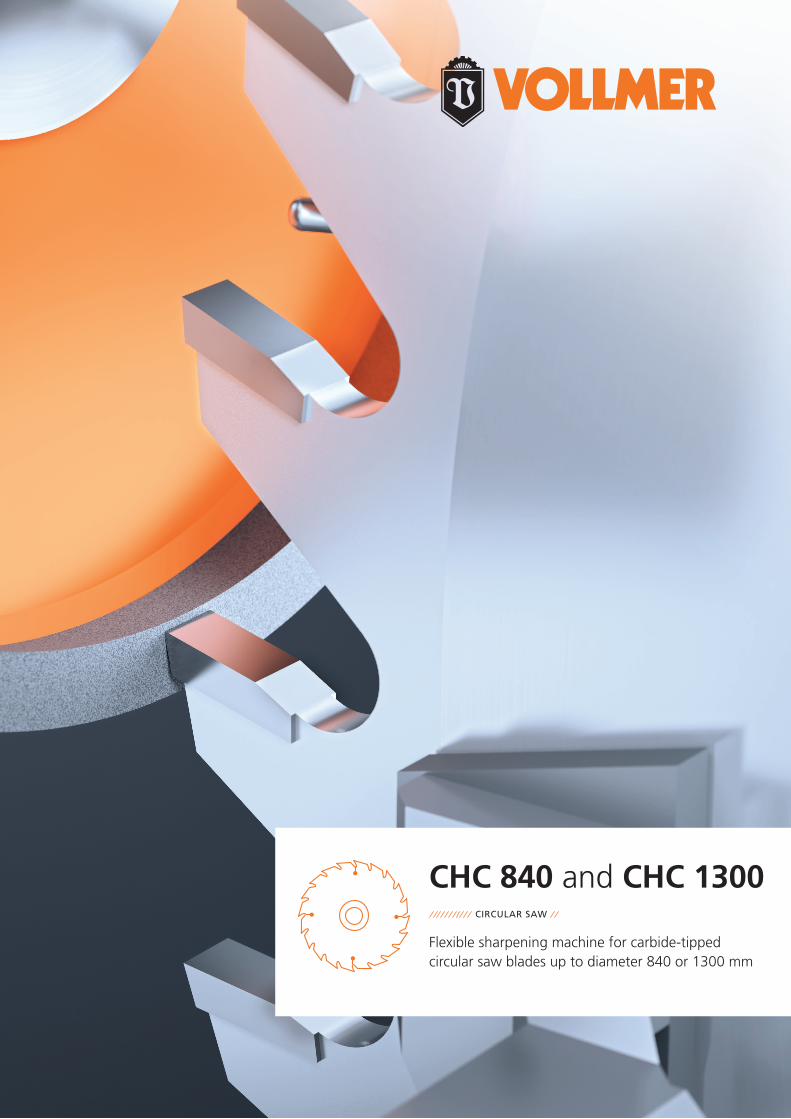
HIGH PERFORMANCE – COMPACT INVESTMENT: CHC 840 and CHC 1300
CIRCULAR SAW TOOTH FACES AND TOOTH TOPS
LARGE VIEWING WINDOW
Internal, two-part operational door for a perfect view of the grinding process
3INNOVATIVE CONTROL PANEL
With 10-inch LCD colour display and multifunction handwheel for fast and safe operation
SOLID DESIGN
Robust machine construction for vibration-free operation and high-quality sharpening result
2
5
COMPACT DESIGN
Space-saving design and optimal accessibility for operators
FULL ENCLOSURE AS STANDARD
For effective safety at work, noise and emission protection, as well as a characteristic appearance
1
4
Machine available for two different diameter ranges: 80 – 840 mm or 80 – 1300 mm
02 03
45 °
15 ° 15 °
n
BedienungCP 200
DIS-Nr. 10000280593/de/-
6-16 © Copyright
6.5.3 Werkzeug-Adaption
Die Schleifscheiben werden auf einem Aufnahmeflansch montiert, auf dem sie bis zur kompletten Ab-nutzung verschraubt bleiben. Dies gewährleistet auch nach einem Schleifscheibenwechsel, eine immergleichbleibende Position auf der Schleifspindel. Dadurch werden kleine Rund- und Planlaufabwei-chungen der Schleifscheibe durch die Abnutzung nach und nach egalisiert.Die Aufnahmeflansche dürfen keinerlei Beschädigungen aufweisen und müssen bei der Montage derSchleifscheibe absolut sauber sein.
6.5.3.1 Auswahl des Aufnahmeflansches
Skizze (Beispiel) Einsatz
32 mm 125 mm -
32 mm 125 mm 18 mm
6.5.4 Werkzeug-Referenzierung
Damit die geforderte Zahngeometrie korrekt auf den positionierten Zahn geschliffen werden kann,muss der Maschinensteuerung die exakten Abmessungen der Schleifscheibe bekannt sein. Dies er-folgt je nach Ausbaustufe wie folgt.
6.5.4.1 Schleifscheiben-Messeinrichtung
Die Position des Schleifscheibenbelags muss bei jeder neu eingesetzten Schleifscheibe mit Hilfe einerMesseinrichtung manuell ermittelt und in die Maschinensteuerung eingegeben werden.
Skizze (Beispiel)
CIRCULAR SAW TOOTH FACES AND TOOTH TOPS
/// THE MACHINE CONCEPT
The CHC series is ideally equipped for sharpening car-bide-tipped circular saw blades. Offering versatility that leaves nothing to be desired, yet with numerous options.
/// Four CNC-controlled axes for the complete machining of all commonly used tooth geometries in just one cycle – even for saws with axial angle and group toothing
/// Oscillation grinding as standard – for high material re-moval rates in just one cycle, e.g. when machining teeth for repair
/// Motor-driven hook and clearance angle adjustment for rapid switchover from face to top grinding
/// Optimum movement coordination for short grinding times and reduced non-productive times
/// Consistently hydraulic-free – extremely low-maintenance
/// Automatic central lubrication included in the basic equipment for reduced maintenance effort
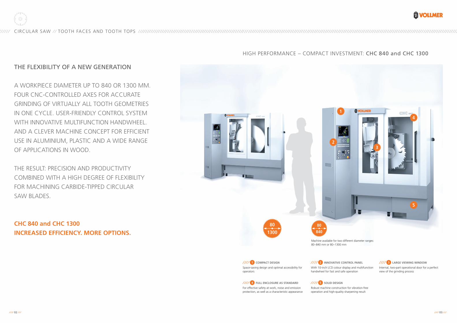
//// MAXIMUM FLEXIBILITYthanks to four CNC-controlled axes (B1, Z1, X1, V1)
//// TOOTH FACE MACHINING
//// TOOTH TOP MACHINING
Its high level of variability and functionality makes the CHC series the first choice in each case for the workshop-orient-ed sharpening of circular saw blades in the processing of al-uminium, plastic and, in particular, wood. Can be flexibly used by sharpening services, small batch manufacturers and, of course, saw mills. Thanks to the diagonally integrat-ed feed pawl with pneumatic lift, even chipper segments present no problem – even if these are screwed with or without a reinforcing ring onto the mounting devices man-ufactured specially for the purpose, often also with filler pieces in order to fill up the gaps in the body.
/// Wide-opening blade clamping mechanism for saws with collar or reinforcing ring
/// Optional second feed pawl for machining tooth pitches up to 180 mm
/// Optional hollow face grinding device for machining hollow face saws
/// APPLICATION
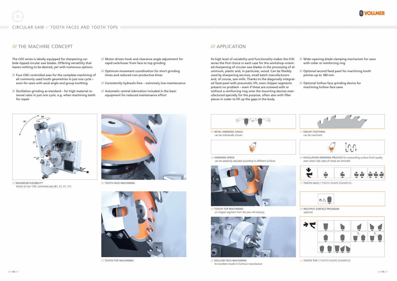
//// HOLLOW FACE MACHININGfor excellent results in furniture manufacture
//// OSCILLATION GRINDING PROCESS for outstanding surface finish quality even when high rates of metal are removed
//// MULTIPLE SURFACE PROGRAMoptional
//// GRINDING SPEEDcan be steplessly adjusted according to different surfaces
//// BEVEL GRINDING ANGLEcan be individually chosen
//// GROUP TOOTHINGcan be machined
//// TOOTH TOP // TOOTH SHAPE EXAMPLES
//// TOOTH FACE // TOOTH SHAPE EXAMPLES
//// TOOTH TOP MACHININGon chipper segment from the saw mill industry
04 05
80
840
1980
0
1900 0
1435 0
80
1300
1980
0
2360 0
1435 0
4
2
3
1
N E U
CIRCULAR SAW TOOTH FACES AND TOOTH TOPS
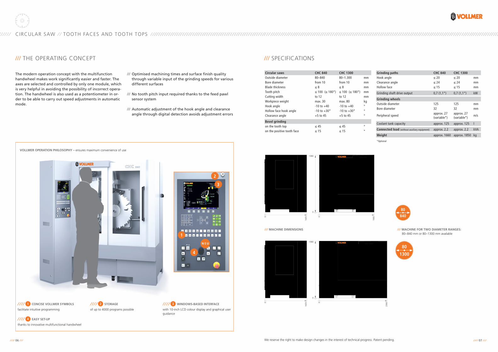
/// THE OPERATING CONCEPT
The modern operation concept with the multifunction handwheel makes work significantly easier and faster. The axes are selected and controlled by only one module, which is very helpful in avoiding the possibility of incorrect opera-tion. The handwheel is also used as a potentiometer in or-der to be able to carry out speed adjustments in automatic mode.
/// Optimised machining times and surface finish quality through variable input of the grinding speeds for various different surfaces
/// No tooth pitch input required thanks to the feed pawl sensor system
/// Automatic adjustment of the hook angle and clearance angle through digital detection avoids adjustment errors
VOLLMER OPERATION PHILOSOPHY – ensures maximum convenience of use
CONCISE VOLLMER SYMBOLS
facilitate intuitive programming
1 WINDOWS-BASED INTERFACE
with 10-inch LCD colour display and graphical user guidance
3
EASY SET-UP
thanks to innovative multifunctional handwheel
4
STORAGE
of up to 4000 programs possible
2
/// SPECIFICATIONS
Circular saws CHC 840 CHC 1300Outside diameter 80–840 80–1.300 mmBore diameter from 10 from 10 mmBlade thickness ≤ 8 ≤ 8 mmTooth pitch ≤ 100 (≤ 180*) ≤ 100 (≤ 180*) mmCutting width to 12 to 12 mmWorkpiece weight max. 30 max. 80 kgHook angle -10 to +40 -10 to +40 °Hollow face hook angle -10 to +30* -10 to +30* °Clearance angle +5 to 45 +5 to 45 °
Bevel grindingon the tooth top ≤ 45 ≤ 45 °on the positive tooth face ≤ 15 ≤ 15 °
Grinding paths CHC 840 CHC 1300Hook angle ≤ 20 ≤ 20 mmClearance angle ≤ 24 ≤ 24 mmHollow face ≤ 15 ≤ 15 mm
Grinding shaft drive output 0,7 (1,1*) 0,7 (1,1*) kW
Grinding wheelsOutside diameter 125 125 mmBore diameter 32 32 mm
Peripheral speedapprox. 27 (variable*)
approx. 27 (variable*)
m/s
Coolant tank capacity approx. 125 approx. 125 l
Connected load (without auxiliary equipment) approx. 2.2 approx. 2.2 kVA
Weight approx. 1660 approx. 1850 kg
*Optional
//// MACHINE FOR TWO DIAMETER RANGES: 80 – 840 mm or 80 – 1300 mm available
//// MACHINE DIMENSIONS
We reserve the right to make design changes in the interest of technical progress. Patent pending.06 07
www.vollmer-group.comVOLLMER WERKE Maschinenfabrik GmbHEhinger Straße 34 // D-88400 Biberach/Riß
Tel. +49 7351 5710 // Fax +49 7351 [email protected] www.vollmer-group.com
VOLLMER WERKE Maschinenfabrik GmbHEhinger Straße 34 // D-88400 Biberach/Riß
Tel. +49 7351 5710 // Fax +49 7351 [email protected]
743/
en/5
00/0
5.19
/Hol
zer
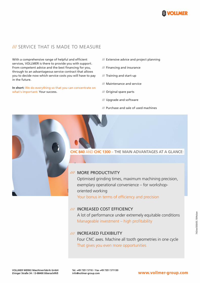
CHC 840 AND CHC 1300 – THE MAIN ADVANTAGES AT A GLANCE:
MORE PRODUCTIVITYOptimised grinding times, maximum machining precision, exemplary operational convenience – for workshop- oriented working Your bonus in terms of efficiency and precision
INCREASED COST EFFICIENCYA lot of performance under extremely equitable conditions Manageable investment – high profitability
INCREASED FLEXIBILITYFour CNC axes. Machine all tooth geometries in one cycle That gives you even more opportunities
With a comprehensive range of helpful and efficient services, VOLLMER is there to provide you with support. From competent advice and the best financing for you, through to an advantageous service contract that allows you to decide now which service costs you will have to pay in the future.
In short: We do everything so that you can concentrate on what's important: Your success.
/// SERVICE THAT IS MADE TO MEASURE
/// Extensive advice and project planning
/// Financing and insurance
/// Training and start-up
/// Maintenance and service
/// Original spare parts
/// Upgrade and software
/// Purchase and sale of used machines