Embed Size (px)
Citation preview

Cooper Industries Inc. Crouse-Hinds Division IF 1544 PO Box 4999, Rev 1 Syracuse, New York 13221 • U.S.A. New 01/08 Copyright© 2007, Cooper Industries, Inc.
CHB204 -2S, PB, X; 205-11S; 204-2S, PB; 208-2S; 304-2S; 305-2S Obstruction Lighting System IF 1544
Front Matter
Abstract This manual contains information and instructions for installing, operating and maintaining the CHB 204, 304, 205, 305, 207 and 208 Obstruction Lighting Systems.
Copyright Copyright © 2007, Cooper Crouse-Hinds, Syracuse, NY 13221
All rights reserved. Reproduction or use of any portion of this manual is prohibited without express written permission from Cooper Crouse-Hinds and/or its licenser.
Trademark Acknowledgements Cooper Crouse-Hinds is a registered trademark name.
All trademarks and product names mentioned are properties of their respective companies, and are recognized and acknowledged as such by Cooper Crouse-Hinds.
Applicable Specifications This equipment meets or exceeds requirements for an FAA Type L-856 and L-857.
Disclaimer While every effort has been made to ensure that the information in this manual is complete, accurate and up-to-date, Cooper Crouse-Hinds assumes no liability for damages resulting from any errors or omissions in this manual, or from the use of the information contained herein. Cooper Crouse-Hinds reserves the right to revise this manual without obligation to notify any person or organization of the revision.
In no event will Cooper Crouse-Hinds be liable for direct, indirect, special, incidental, or consequential damages arising out of the use of or the inability to use this manual.
SAVE THESE INSTRUCTIONS FOR FUTURE REFERENCE
Cooper Industries Inc. Crouse-Hinds Division IF 1544 PO Box 4999, Rev 1 Syracuse, New York 13221 • U.S.A. New 01/08 Copyright© 2007, Cooper Industries, Inc.
Warranty Cooper Crouse-Hinds warrants all components, under normal operating conditions, for 2 years.
Parts Replacement The use of parts or components, in this equipment, not manufactured or supplied by Cooper Crouse-Hinds voids the warranty and invalidates the third party testing laboratory certification which ensures compliance with FAA Advisory Circulars 150/5345-43E, 150/5345-51 and 150/4345-53B. The certification is valid as long as the system is maintained in accordance with FAA guidelines (FR doc. 04-13718 filed 6-16-04).
Personnel Hazard Warning
Dangerous Voltages Dangerous line voltages reside in certain locations in this equipment. Also, this equipment may generate dangerous voltages. Although Cooper Crouse-Hinds has incorporated every practical safety precaution, exercise extreme caution at all times when you expose circuits and components, and when you operate, maintain, or service this equipment.
Avoid Touching Live Circuits Avoid touching any component or any part of the circuitry while the equipment is operating. Do not change components or make adjustments inside the equipment with power on.
Dangerous Voltages Can Persist with Power Disconnected Under certain conditions, dangerous voltages can be present because capacitors can retain charges even after the power has been disconnected.
Protect yourself — always turn off the input (primary) power and wait for one minute for storage capacitors to drain their charge. Then check between the red and blue wires on the flashhead terminal block with a voltmeter for any residual charge before touching any circuit element or component.
Do Not Depend on Interlocks Never depend on interlocks alone to remove unsafe voltages. Always check circuits with a voltmeter. Under no circumstances remove or alter any safety interlock switch.
Cooper Industries Inc. Crouse-Hinds Division IF 1544 PO Box 4999, Rev 1 Syracuse, New York 13221 • U.S.A. New 01/08 Copyright© 2007, Cooper Industries, Inc.
Table of Contents CHB 204-2S,PB,X; 205-11S; 207-2S,PB; 208-2S; 304-2S; 305-2S..... Error! Bookmark not defined. Front Matter ............................................................................................................................... i
Abstract .................................................................................................................................. i Copyright ............................................................................................................................... i Trademark Acknowledgements ............................................................................................. i Applicable Specifications ...................................................................................................... i Disclaimer .............................................................................................................................. i Warranty ............................................................................................................................... ii Parts Replacement................................................................................................................. ii
Personnel Hazard Warning ....................................................................................................... ii Dangerous Voltages .............................................................................................................. ii Avoid Touching Live Circuits .............................................................................................. ii Dangerous Voltages Can Persist with Power Disconnected................................................. ii Do Not Depend on Interlocks ............................................................................................... ii
Table of Contents..................................................................................................................... iii List of Figures ........................................................................................................................... v Section 1 – Introduction and Operation .................................................................................... 1
System Controller ................................................................................................................. 1 Variations and Options ......................................................................................................... 1 Specifications........................................................................................................................ 1
Physical ............................................................................................................................. 1 Performance Characteristics ............................................................................................. 1
Operation............................................................................................................................... 2 Beacon/Power Converter .................................................................................................. 2 Catenary Operation (CHB 207, 208) ................................................................................ 2 Flash Modes ...................................................................................................................... 2 60/50 Hz Operation........................................................................................................... 2 Fixed Mode Operation ...................................................................................................... 2
Configuring PCB1 ................................................................................................................ 3 Section 2 - Mounting and Installation....................................................................................... 7
Unpacking ............................................................................................................................. 7 Tools ..................................................................................................................................... 7 Access ................................................................................................................................... 7
HAZARD WARNING...................................................................................................... 7 Beacon/Power Converter .................................................................................................. 7 Flashhead .......................................................................................................................... 7
Mounting............................................................................................................................... 7 Beacon Location ............................................................................................................... 8 Beacon Angle.................................................................................................................... 8 Controller Mounting ......................................................................................................... 8 PEC Mounting .................................................................................................................. 8
Wiring ................................................................................................................................... 8 Beacon Wiring .................................................................................................................. 9 Lightning Protection ......................................................................................................... 9

Cooper Industries Inc. Crouse-Hinds Division IF 1544 PO Box 4999, Rev 1 Syracuse, New York 13221 • U.S.A. New 01/08 Copyright© 2007, Cooper Industries, Inc.
Installation Checklist .......................................................................................................... 10 Section 3 — Maintenance and Troubleshooting..................................................................... 22
Safety .................................................................................................................................. 22 Preventive Maintenance...................................................................................................... 22 Storage ................................................................................................................................ 22 RFI Problems ...................................................................................................................... 22 Component Testing............................................................................................................. 23
Wiring and Cabling......................................................................................................... 23 Inspection........................................................................................................................ 23 Capacitors ....................................................................................................................... 23 C1 — High Intensity Capacitor Bank............................................................................. 23 C2 — Medium Intensity Capacitor................................................................................. 23 C3 — Low Intensity Capacitor ....................................................................................... 24 C4 — Tuning Capacitor.................................................................................................. 24 FT101 — Flashtube ........................................................................................................ 24 K1, K2 — Mode Relays, 24-volt DC Coil...................................................................... 24 K3 — Discharge Relay, 120 VAC Coil.......................................................................... 24 L1 — Burst Choke .......................................................................................................... 24 L2 — Flash Choke .......................................................................................................... 24 PCB1 — Timing and Trigger Board............................................................................... 24 R1A, R1B — Bleed Resistors......................................................................................... 24 PCB2 — HV Rectifier Board ......................................................................................... 24 R2A, R2B — Burst Resistors ......................................................................................... 24 T1 — Power Transformer............................................................................................... 24 PCB3 — Sense Module .................................................................................................. 25 T101 — Trigger Transformer ......................................................................................... 25 VR1 — Suppressor Assembly ........................................................................................ 25
Troubleshooting .................................................................................................................. 25 Component Removal and Replacement.............................................................................. 28
Removal & Replacement — General ............................................................................. 28 Section 4 – Recommended Spare & Replaceable Parts.......................................................... 32
Customer Service ................................................................................................................ 32 Ordering Parts ..................................................................................................................... 32 Beacon / Power Converter Parts ......................................................................................... 32 Flashhead Parts ................................................................................................................... 32 Returning Equipment – Return Material Authorization (RMA)......................................... 37
Return to Stock Policy .................................................................................................... 38 Appendix 1 – Programming the Timing and Trigger Board................................................... 39
Connecting the Handheld.................................................................................................... 39 Using the Programmer ........................................................................................................ 39
SETUP for Non S Versions ............................................................................................ 41 SETUP for S Versions .................................................................................................... 41 Parameters for Non S Versions....................................................................................... 41 Parameters for S Versions............................................................................................... 42 INFO ............................................................................................................................... 43 MODE CHANGE ........................................................................................................... 43
Appendix 2 - CHB 204SPB and 207SPB Primary Backup .................................................... 45 Operation............................................................................................................................. 45

Cooper Industries Inc. Crouse-Hinds Division IF 1544 PO Box 4999, Rev 1 Syracuse, New York 13221 • U.S.A. New 01/08 Copyright© 2007, Cooper Industries, Inc.
Installation........................................................................................................................... 45 Appendix 3 - CHB 204-2X and 204-2SX Extended Separation............................................. 48
Introduction and Operation ................................................................................................. 48 Mounting and Installation ................................................................................................... 48
Flashhead Wiring ............................................................................................................ 48 Securing the Cable .......................................................................................................... 48
Spare Parts (for 204-2X/204-2SX versions only)............................................................... 52
List of Figures Figure 1-1 – PCB1 (2904411) Timing and Trigger Board ....................................................... 4 Figure 1-3 – Typical 2-Tower 3-Tier Layout and Catenary Beacon Operation ....................... 6 Figure 2-1 – PC 204/207 Power Converter Mounting and Outline ........................................ 12 Figure 2-2 – FH 204 Flashhead Mounting and Outline.......................................................... 13 Figure 2-3 – CHB 205/208 Beacon Mounting and Outline.................................................... 14 Figure 2-4 – Wiring Overview of a System............................................................................ 15 Figure 2-5 – Junction Box, Three-Phase Installation Wiring ................................................. 16 Figure 2-6 – Single-Phase Installation Wiring for CH 204/207 ............................................. 17 Figure 2-7 – Single-Phase Installation Wiring for CH 205/208 ............................................. 18 Figure 2-8 – Optical Assembly Internal Wiring ..................................................................... 19 Figure 2-9 – PC 204/207 Power Converter Internal Wiring................................................... 20 Figure 2-10 – PC 205/208 Power Converter Internal Wiring................................................. 21 Figure 3-1 – Major Troubleshooting Symptoms .................................................................... 26 Figure 3-2 – Defective Component Locator Code.................................................................. 27 Figure 3-3 – Winding Directions ............................................................................................ 30 Figure 4-1 – Beacon / Power Converter Replacement Parts................................................... 33 Figure 4-2 – PC 204/207 Power Converter Component Locations ........................................ 34 Figure 4-3 – PC 205/208 Power Converter Component Locations ........................................ 35 Figure 4-4 – Flashhead Replacement Parts............................................................................. 36 Figure 4-5 – CHB 205 Optical Assembly, FH 204 Flash Component Locations................... 36 Figure A1-1 – DB9 Female..................................................................................................... 39 Figure A1-2 – Handheld Programmer .................................................................................... 39 Figure A2-1 – PC 204SPB / 207SPB Installation Wiring ...................................................... 46 Figure A2-2 – PC 204SPB / 207SPB Internal Wiring............................................................ 47 Figure A3-1 – PC 204-2X / 204-2SX Mid-Tower Installation Example................................ 49 Figure A3-2 – PC 204-2X / 204-2SX Ground Level Installation Example............................ 50 Figure A3-3 – PC 204-2X / 204-2SX Component Locations................................................. 51 Figure A3-4 – PC 204-2X / 204-2SX Internal Wiring ........................................................... 51


Cooper Industries Inc. Crouse-Hinds Division IF 1544 PO Box 4999, Rev 1 Syracuse, New York 13221 • U.S.A. New 01/08 Copyright© 2007, Cooper Industries, Inc.
Section 1 – Introduction and Operation
The CHB 204 High Intensity Beacon consists of an FH 204 Flashhead and a PC 204 Power Converter in separate enclosures.
The CHB 207 High Intensity Catenary Beacon consists of an FH 204 Flashhead and a PC 207 Power Converter in separate enclosures.
The CHB 205 High Intensity Beacon is a self-contained unit with an optical assembly mounted in the enclosure.
The CHB 208 High Intensity Catenary Beacon is a self-contained unit with an optical assembly mounted in the enclosure.
System Controller For standard (non-S) versions an CHC 140 system controller directs flash timing and intensity, and records and reports Beacon operating status. It enables either automatic or manual intensity control, and it continuously displays the flashing status of each Beacon. For further information, consult the CHC 140 System Controller Manual.
For S versions a CHC 121 system controller monitors the status and operating parameters of the lights. The lights can be interrogated by the controller, or remotely via a telephone line connected to the controller. The controller sends intensity information to the lights to make them operate in the correct mode. The controller sends and receives coded signals over a two-wire communications cable (COMM LINK).
Variations and Options The CHB304/305 (S) medium intensity systems operate in twilight and night modes only. In this case, wherever 204 and 205 appear in the manual substitute 304 and 305, respectively. Contact Customer Service at 1-800-821-5825 for a description of equipment variations and options.
Specifications
Physical PC 204/207 (H x W x D, Weight)
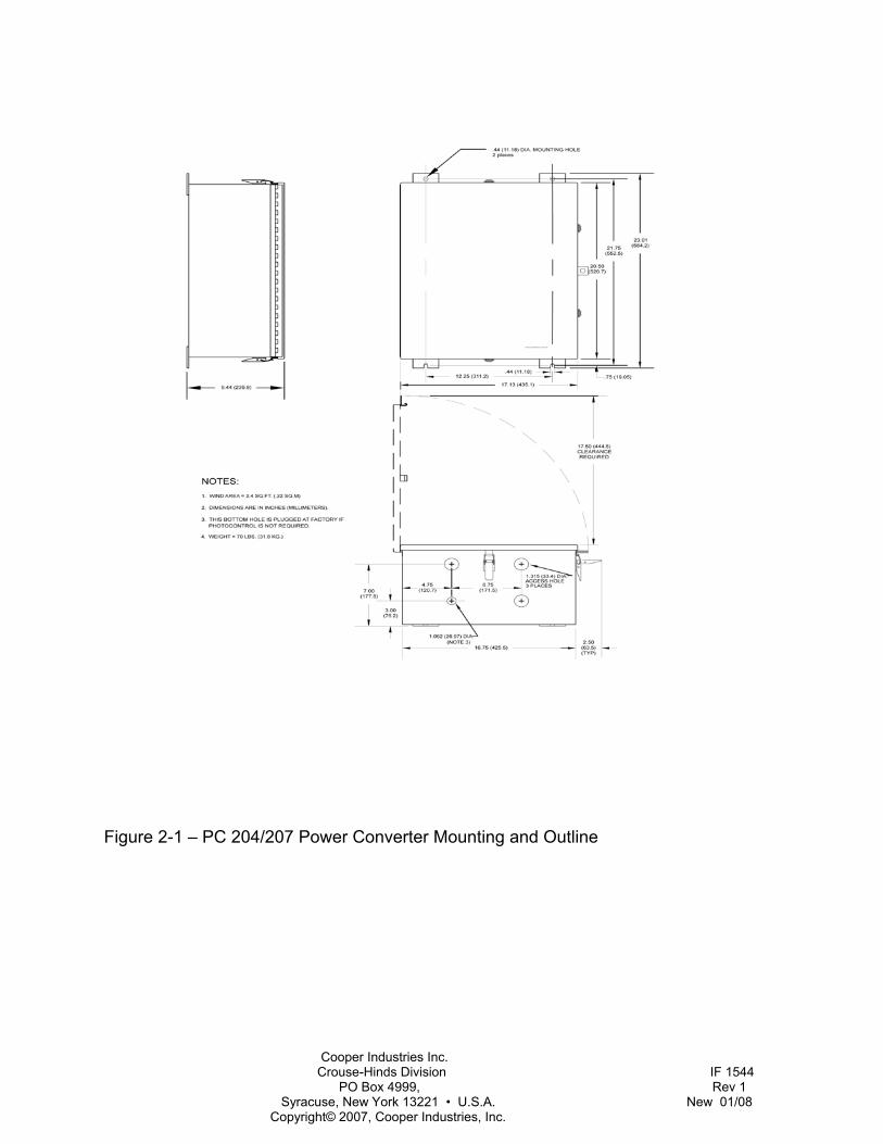
23 x 17.13 x 9.44 in., 70lbs. 584.2 x 435.1 x 239.8 mm, 31.8 kg Wind Area: 2.4 ft2, 0.22 m2
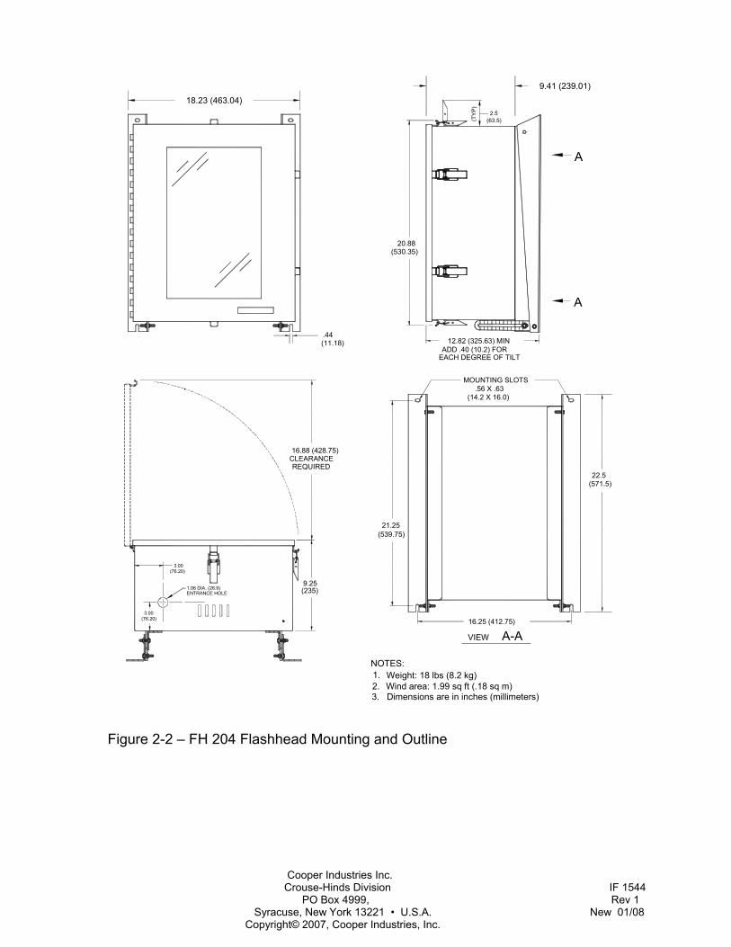
FH 204 (H x W x D, Weight) 23 x 18.6 x 12.8 in., 18lbs 584 x 472 x 325 mm, 8.2 kg Wind Area: 1.99 ft2, 0.18 m2
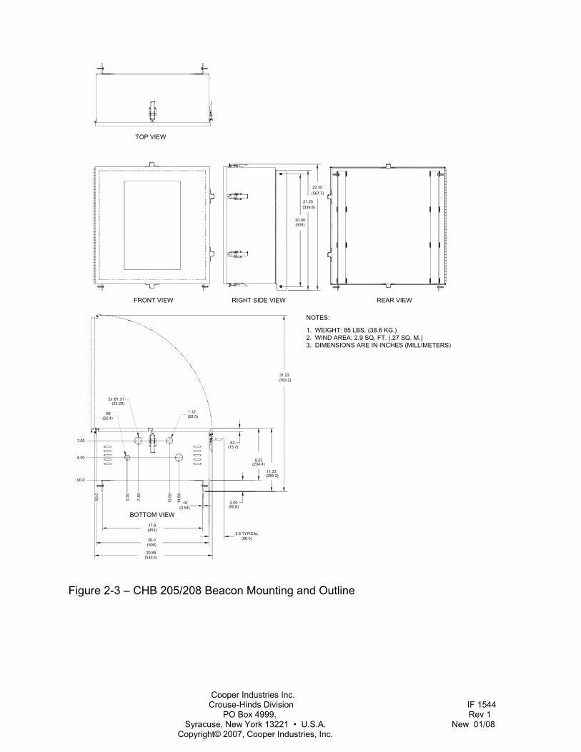
CHB 205/208 (H x W x D, Weight) 22.35 x 20.88 x 11.23 in., 85 lbs. 567.7 x 530.4 x 285.2 mm, 38.6 kg Wind Area: 2.9 ft2, 0.27 m2
Environmental Complies with FAA specifications in
AC 150/5345-43.
Performance Characteristics Application
CHB 204/205 L-856 CHB 207/208 L-857
Flash Intensity (nominal): Day (204/205) 270,000 ± 25%ECD Day (207/208) 140,000 ± 25%ECD Twilight 20,000 ± 25% ECD Night 2,000 ± 25% ECD Beam Spread Horizontal: 120º
Vertical: 3º

Cooper Industries Inc. Crouse-Hinds Division IF 1544 PO Box 4999, Rev 1 Syracuse, New York 13221 • U.S.A. New 01/08 Copyright© 2007, Cooper Industries, Inc.
Flash Rate CHB 204/205 40 flashes per min. CHB 207/208 60 flashes per min.
Electrical (factory pre-wired) AC Voltage
120-480 VAC ± 10%, 60 Hz 110-230 VAC ± 10%, 50 Hz
Volt-Amperes 600 peak Day 255W
Operation The controller determines the operating intensity of the structure lights, and then informs the Timing and Trigger Board (PCB1) in each beacon.
Beacon/Power Converter The beacon starts flashing when power is applied.
A pair of shielded conductors between the beacons and the controller carries the control and monitoring signals for an entire system. A beacon sends a flash confirmation signal to the controller for monitoring. Individual encoding identifies the beacon of origin, thus enabling all beacons in a system to individually report to the controller.
All beacons are capacitive discharge lights that use a xenon flashtube.
If the controller is disconnected, or fails, all beacons flash by default at high intensity.
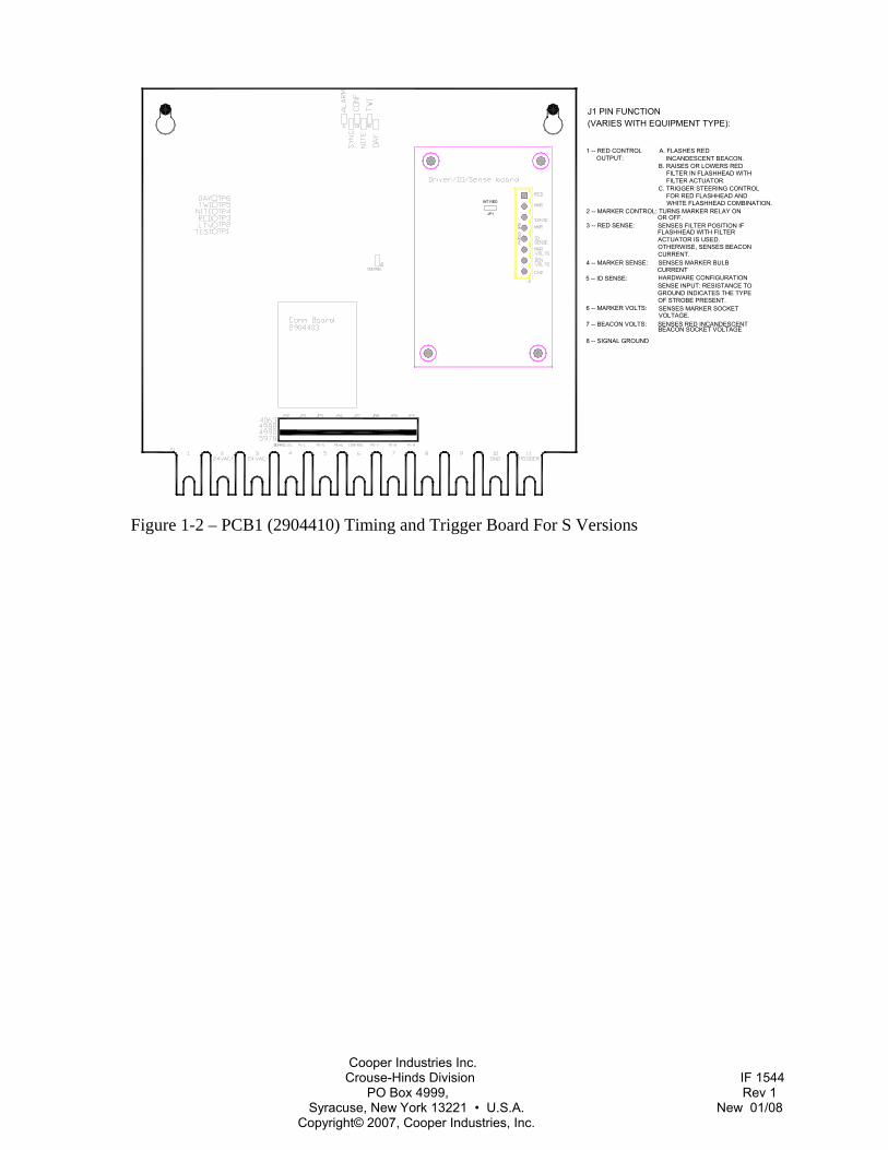
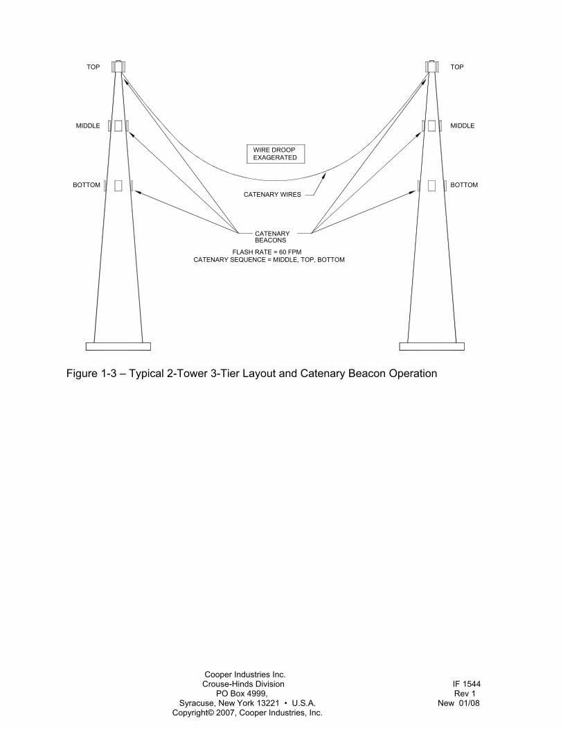
Catenary Operation (CHB 207, 208) High intensity lights for towers that support catenary wires provides the highest degree of visibility in daylight and night. Three levels (tiers) of sequentially flashing lights are required. One tier of lighting is required at the top, one tier at the midpoint, and one tier at the bottom.
The tier flash sequence is middle, top, bottom. All lights at the same tier flash
simultaneously. The catenary flash rate is 60 flashes per minute. See
Cooper Crouse-Hinds uses a standard format: it refers to the lowest level as Tier 1 and the most northerly facing light as beacon 1. Higher numbered beacons are placed around the structure in a North-East-South-West direction. Figure 1-3 shows a typical installation.
Flash Modes
Night At nightfall, the controller switches the beacon to night mode operation; the flashhead flashes at the night intensity of 2,000 ± 25% ECD.
Twilight At twilight, the controller switches the beacon to twilight mode operation; the flashhead flashes at the twilight intensity of 20,000 ± 25% ECD.
Day At daybreak, the controller switches the beacon to day mode operation; the flashhead flashes at the daylight intensity of 270,000 ± 25% ECD.
60/50 Hz Operation PCB1 can operate from either a 60Hz or a 50Hz power source.
Fixed Mode Operation The following table explains how to force the beacon to operate continuously at a fixed flash intensity (mode). Use these procedures to check operation at all three flash intensities. You can also use the handheld terminal to control the modes (see section 5).
Cooper Industries Inc. Crouse-Hinds Division IF 1544 PO Box 4999, Rev 1 Syracuse, New York 13221 • U.S.A. New 01/08 Copyright© 2007, Cooper Industries, Inc.
Intensity Procedure† DAY (High) Place a jumper between
Test Point 1 (TP1) labeled TEST and TP6 labeled DAY.
TWI (Twilight)
Place a jumper between Test Point 1 (TP1) labeled TEST and TP5 labeled TWI.
HITE (Low) Place a jumper between Test Point 1 (TP1) labeled TEST and TP4 labeled NITE.
LTV Factory use only. Causes continuous triggering. Do not use.
Be certain to remove all jumpers after checking the beacon.
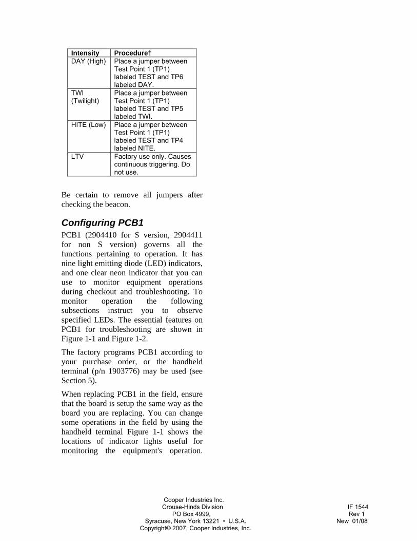
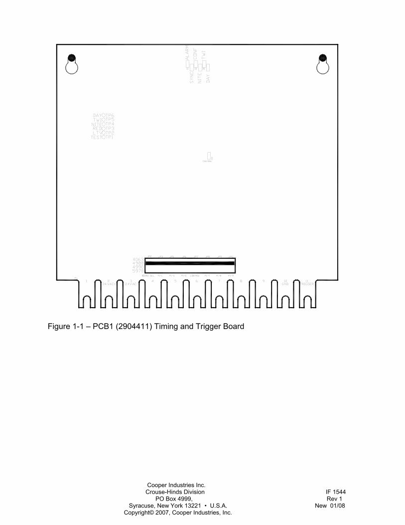
Configuring PCB1 PCB1 (2904410 for S version, 2904411 for non S version) governs all the functions pertaining to operation. It has nine light emitting diode (LED) indicators, and one clear neon indicator that you can use to monitor equipment operations during checkout and troubleshooting. To monitor operation the following subsections instruct you to observe specified LEDs. The essential features on PCB1 for troubleshooting are shown in Figure 1-1 and Figure 1-2.
The factory programs PCB1 according to your purchase order, or the handheld terminal (p/n 1903776) may be used (see Section 5).
When replacing PCB1 in the field, ensure that the board is setup the same way as the board you are replacing. You can change some operations in the field by using the handheld terminal Figure 1-1 shows the locations of indicator lights useful for monitoring the equipment's operation.
Cooper Industries Inc. Crouse-Hinds Division IF 1544 PO Box 4999, Rev 1 Syracuse, New York 13221 • U.S.A. New 01/08 Copyright© 2007, Cooper Industries, Inc.
Figure 1-1 – PCB1 (2904411) Timing and Trigger Board
Cooper Industries Inc. Crouse-Hinds Division IF 1544 PO Box 4999, Rev 1 Syracuse, New York 13221 • U.S.A. New 01/08 Copyright© 2007, Cooper Industries, Inc.
WHITE FLASHHEAD COMBINATION.
8 -- SIGNAL GROUND
7 -- BEACON VOLTS:
6 -- MARKER VOLTS:
5 -- ID SENSE:
4 -- MARKER SENSE: SENSES MARKER BULB
3 -- RED SENSE:
2 -- MARKER CONTROL: TURNS MARKER RELAY ON
OUTPUT:1 -- RED CONTROL A. FLASHES RED
SENSES RED INCANDESCENT
SENSES MARKER SOCKET
HARDWARE CONFIGURATION
VOLTAGE.
CURRENT
BEACON SOCKET VOLTAGE
OF STROBE PRESENT.GROUND INDICATES THE TYPE
SENSE INPUT: RESISTANCE TO
SENSES FILTER POSITION IF
CURRENT.OTHERWISE, SENSES BEACONACTUATOR IS USED.FLASHHEAD WITH FILTER
OR OFF.
FOR RED FLASHHEAD AND
FILTER ACTUATOR.FILTER IN FLASHHEAD WITH
INCANDESCENT BEACON.
C. TRIGGER STEERING CONTROL
B. RAISES OR LOWERS RED
(VARIES WITH EQUIPMENT TYPE):J1 PIN FUNCTION
INT RED
JP1
Figure 1-2 – PCB1 (2904410) Timing and Trigger Board For S Versions
Cooper Industries Inc. Crouse-Hinds Division IF 1544 PO Box 4999, Rev 1 Syracuse, New York 13221 • U.S.A. New 01/08 Copyright© 2007, Cooper Industries, Inc.
CATENARY WIRES
CATENARYBEACONS
TOP
MIDDLE
BOTTOMBOTTOM
MIDDLE
TOP
WIRE DROOPEXAGERATED
FLASH RATE = 60 FPMCATENARY SEQUENCE = MIDDLE, TOP, BOTTOM
Figure 1-3 – Typical 2-Tower 3-Tier Layout and Catenary Beacon Operation

Cooper Industries Inc. Crouse-Hinds Division IF 1544 PO Box 4999, Rev 1 Syracuse, New York 13221 • U.S.A. New 01/08 Copyright© 2007, Cooper Industries, Inc.
Section 2 - Mounting and Installation
Unpacking Inspect shipping cartons for signs of damage before opening. Check package contents against the packing list and inspect each item for visible damage, and promptly report damage claims to the freight handler.
Cooper Crouse-Hinds factory programs beacons for operation at particular locations, and marks the shipping containers accordingly on the outside. Cooper Crouse-Hinds refers to the lowest level as Tier 1 and the most northerly facing light as Beacon 1. Higher numbered beacons are placed around the structure in a North-East-South-West direction. Therefore, you must maintain the beacon’s identity according to the package identity of each beacon (for example, Beacon 1, Tier 1; Beacon 2, Tier 1; and so forth), and install it as called out on drawings.
Tools Although no special tools are necessary, the following hand tools are suggested for installation and maintenance:
• #1 Phillips-head screwdriver, 8-inch long shank
• #2 Phillips-head screwdriver • 3/16-in. flat blade screwdriver • 1/4-inch flat blade screwdriver • Medium slip-joint pliers • 8-in. or 10-in. adjustable wrench • Assorted nut drivers and combination
wrenches • Hand tools for electrical wiring • Triplett™ Model 630-NA VOM, or
equivalent analog volt-ohm meter, or a
digital meter with an averaging function.
Access
HAZARD WARNING Disconnect the primary power before opening the beacon or flashhead enclosures.
Beacon/Power Converter Latches secure the hinged cover of the power converter or the beacon. When you release these you can swing open the cover for access to the inside.
Flashhead Latches secure the hinged cover of the flashhead. When you release these you can swing open the cover for access to the inside.
Mounting Outline, mounting, and clearance dimensions for your equipment are shown in the following figures:
• Figure 2-1 – PC 204 or PC 207 Power Converter Mounting and Outline
• Figure 2-2 – FH 204 Flashhead Mounting and Outline
• Figure 2-3 – CHB 205 or CHB 208 Beacon Mounting and Outline
Cooper Industries Inc. Crouse-Hinds Division IF 1544 PO Box 4999, Rev 1 Syracuse, New York 13221 • U.S.A. New 01/08 Copyright© 2007, Cooper Industries, Inc.
Beacon Location FAA Guidelines for beacon placement are published in AC 70/7460-1. Avoid placing a beacon within a strong radio frequency (RF) field. For example, a beacon within four feet of a radiating FM antenna is likely to pick up electromagnetic interference (EMI) that could cause improper operation or damage. Place a beacon at an adequate distance from a powerful RF radiator. Contact the factory for instructions when you cannot avoid this situation.
Beacon Angle NOTE
Beacons (except AOL lights) are installed with specific elevation angles.
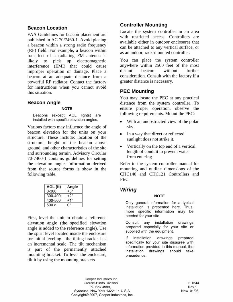
Various factors may influence the angle of beacon elevation for the units on your structure. These include: location of the structure, height of the beacon above ground, and other characteristics of the site and surrounding terrain. Advisory Circular 70-7460-1 contains guidelines for setting the elevation angle. Information derived from that source forms is show in the following table.
AGL (ft) Angle 0-300 +3° 300-400 +2° 400-500 +1° 500 > 0°
First, level the unit to obtain a reference elevation angle (the specified elevation angle is added to the reference angle). Use the spirit level located inside the enclosure for initial leveling—the tilting bracket has an incremental scale. The tilt mechanism is part of the permanently attached mounting bracket. To level the enclosure, tilt it by using the mounting brackets.
Controller Mounting Locate the system controller in an area with restricted access. Controllers are available either in outdoor enclosures that can be attached to any vertical surface, or as an indoor, rack-mounted controller.
You can place the system controller anywhere within 2500 feet of the most distant beacon without further consideration. Consult with the factory if a greater distance is necessary.
PEC Mounting You may locate the PEC at any practical distance from the system controller. To ensure proper operation, observe the following requirements. Mount the PEC:
• With an unobstructed view of the polar sky.
• In a way that direct or reflected sunlight does not strike it.
• Vertically on the top end of a vertical length of conduit to prevent water from entering.
Refer to the system controller manual for mounting and outline dimensions of the CHC140 and CHC121 Controllers and PEC.
Wiring NOTE
Only general information for a typical installation is presented here. Thus, more specific information may be needed for your site.
Consult any installation drawings prepared especially for your site or supplied with the equipment.
If installation drawings prepared specifically for your site disagree with information provided in this manual, the installation drawings should take precedence.
Cooper Industries Inc. Crouse-Hinds Division IF 1544 PO Box 4999, Rev 1 Syracuse, New York 13221 • U.S.A. New 01/08 Copyright© 2007, Cooper Industries, Inc.
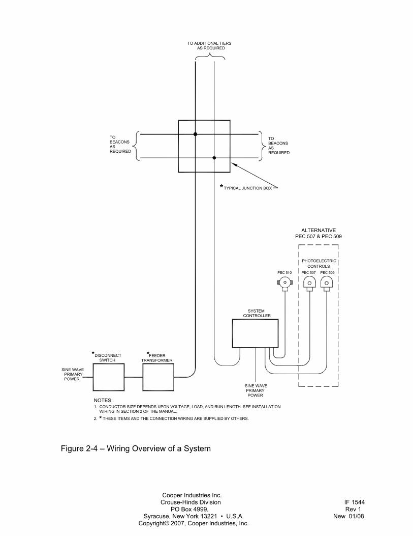
See Figure 2-4 – Wiring Overview of a System. System wiring consists of primary power and signal distribution wiring. Primary power is usually taken from a load center to the various items of equipment. Signal wiring is between the beacons and the system controller. Make connections to beacons at nearby junction boxes. Always position junction boxes below the beacons with drain holes facing downward.
Beacon Wiring Three-phase power often supplies large systems. However, the beacons are single-phase units that are connected from line-to-line (A-B, B-C, A-C). Therefore, phase differences occur between groups of beacons in the same three-phase system. In a three-phase system, phase A-C must supply the controller (not C-A) to allow the controller to be compatible with all beacons. Failure to ensure optimum phasing as described could result in intensity control problems.
Use circuit breakers or a safety switch with fuses for the primary power load center. Insulation should be rated at 600 VDC minimum. Wire size is a factor affected by the service voltage, the number of beacons in the system, and the length of the wire run to the beacons. To determine wire gauge, consider each beacon as a 400 volt-ampere load and do not permit the voltage drop caused by wire resistance to exceed 5% at any beacon. You may use this volt-ampere value to determine ratings for slow-acting fuses or circuit breakers for the system. For fast-acting fuses and a system feeder transformer (if used) consider a peak load of 600 volt-amperes for each beacon. CHCA recommends that you use National Electric Code guidelines for all primary wiring.
A label inside the beacon near the fuse block indicates the operating voltage and
frequency of your beacon. Two internal fuses are sized according to the operating voltage. When Line 2 is neutral, the factory replaces the F2 fuse with a jumper wire.
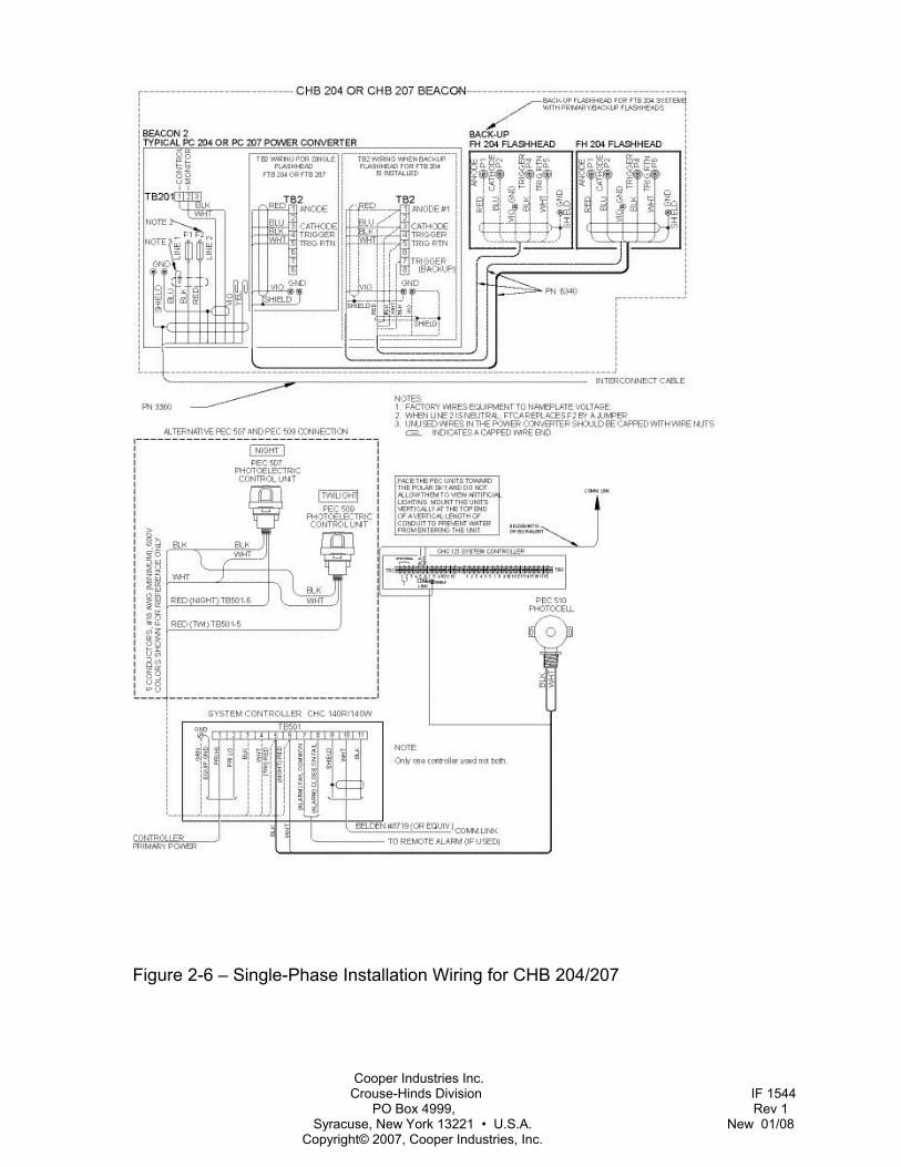
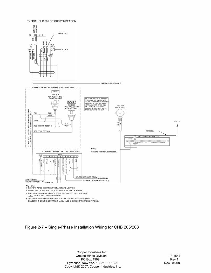
Make connections to distribution wiring at a nearby junction box. Consult the following installation wiring diagrams to guide you in wiring the equipment at your installation:
CAUTION
These figures are guidelines only. If they differ from the installation drawings for your site, use the site installation drawings.
Installation drawings in this manual are as follows:
• Figure 2-5 – Junction Box; Three-phase Installation Wiring
• Figure 2-6 – Single-Phase Installation Wiring for CHB 204 or 207
• Figure 2-7 – Single-Phase Installation Wiring for CHB 205 or 208
Lightning Protection Though ElectroFlash equipment is designed to withstand severe transient over-voltages, a lightning arresting system must be installed to prevent damage by lightning. Install a lightning arresting system to protect a light at the top of a mast or antenna. Transient suppressors from line-to-line and line-to-neutral are recommended at the primary power load center.
Cooper Industries Inc. Crouse-Hinds Division IF 1544 PO Box 4999, Rev 1 Syracuse, New York 13221 • U.S.A. New 01/08 Copyright© 2007, Cooper Industries, Inc.
Installation Checklist Complete the following steps before applying power to the lights.
1. Equipment Damage:
Inspect all equipment for damage.
2. Required Equipment:
Verify the received equipment against the packing list to ensure completeness.
3. Beacon/Power Converter Mounting:
Position and mount each unit correctly, allowing adequate clearance for opening the covers. Also, use the following guidelines:
• Ensure that the case is mounted upright, is water tight, and grounded.
• Check hardware inside the case to ensure that the mounting screws and nuts are tight.
• Ensure that only the bottom of the case has drain holes and that they are clear.
• Ensure that no holes are punched or drilled on the top surface of the case.
• Ensure that air can flow around the case.
• Mount the unit away from radio frequency interference (RFI).
4. Beacon/Power Converter Wiring:
Use the installation drawings and the following guidelines:
• Check for proper incoming service voltage.
• Wire each unit according to the instructions.
• In installations with multiple units, ensure that all units are wired to
the same phase. In installations with multiple tiers and three phase wiring, follow the phasing chart in the installation drawings, or site drawings.
• Check all electrical connections for tightness.
• Check all terminal strip connections for tightness.
• Ground the power converter/beacon using a bonding strap from the case leg to the structure.
5. Flashhead Mounting:
Ensure that the flashhead lens can be opened without striking other objects.
• Level and set the flashhead at the required elevation angle.
6. Flashhead Wiring:
• Ground the flashhead.
• Check the wiring of the flashhead cable to the flashhead.
• Secure the flashhead cable to the tower. Support and tape the flashhead cable to prevent its movement by the wind.
Cooper Industries Inc. Crouse-Hinds Division IF 1544 PO Box 4999, Rev 1 Syracuse, New York 13221 • U.S.A. New 01/08 Copyright© 2007, Cooper Industries, Inc.
7. Photocell:
• Locate photocell where it views unobstructed polar sky with no direct or reflected artificial lighting striking it.
• Mount the photocell vertically on the top end of a vertical length of conduit to prevent water from entering the unit.
• Ground the wire shield around the photocell wires, if one is present.
• After running the photocell wires, check for continuity and shorts.
After completing all the steps listed above, turn on the power and perform an operational checkout from procedures in Section 3 of this manual.
Cooper Industries Inc. Crouse-Hinds Division IF 1544 PO Box 4999, Rev 1 Syracuse, New York 13221 • U.S.A. New 01/08 Copyright© 2007, Cooper Industries, Inc.
Figure 2-1 – PC 204/207 Power Converter Mounting and Outline
Cooper Industries Inc. Crouse-Hinds Division IF 1544 PO Box 4999, Rev 1 Syracuse, New York 13221 • U.S.A. New 01/08 Copyright© 2007, Cooper Industries, Inc.
(76.20)3.00
3.00(76.20)
16.25 (412.75)
12.82 (325.63) MIN
NOTES:
(539.75)21.25
REQUIREDCLEARANCE16.88 (428.75)
(571.5)22.5
(235)9.25
1.06 DIA. (26.9)
(530.35)20.88
A
A
VIEW A-A
1. Weight: 18 lbs (8.2 kg)2.3. Dimensions are in inches (millimeters)
Wind area: 1.99 sq ft (.18 sq m)
(TY
P)
(63.5)2.5
ADD .40 (10.2) FOREACH DEGREE OF TILT
MOUNTING SLOTS.56 X .63
(14.2 X 16.0)
.44(11.18)
ENTRANCE HOLE
18.23 (463.04)
9.41 (239.01)
Figure 2-2 – FH 204 Flashhead Mounting and Outline
Cooper Industries Inc. Crouse-Hinds Division IF 1544 PO Box 4999, Rev 1 Syracuse, New York 13221 • U.S.A. New 01/08 Copyright© 2007, Cooper Industries, Inc.
2x Ø1.31
.62
9.23
11.23
2.00
TOP VIEW
FRONT VIEW
BOTTOM VIEW
RIGHT SIDE VIEW REAR VIEW
NOTES:
1. WEIGHT: 85 LBS. (38.6 KG.)2. WIND AREA: 2.9 SQ. FT. (.27 SQ. M.)3. DIMENSIONS ARE IN INCHES (MILLIMETERS)
(567.7)22.35
20.00
21.25(539.8)
(508)
(33.28)
(50.8)
(15.7)
(234.4)
(285.2)
31.23(793.2)
2.6 TYPICAL(66.0)20.0
(508)
17.8(453)
20.88(530.4)
00.0
5.50
7.50
13.0
0
14.6
8
00.0
4.00
7.00
1.12(28.5)
.88(22.4)
.10(2.54)
Figure 2-3 – CHB 205/208 Beacon Mounting and Outline
Cooper Industries Inc. Crouse-Hinds Division IF 1544 PO Box 4999, Rev 1 Syracuse, New York 13221 • U.S.A. New 01/08 Copyright© 2007, Cooper Industries, Inc.
PRIMARYPOWER
DISCONNECT SWITCH
FEEDER TRANSFORMER
SYSTEMCONTROLLER
PHOTOELECTRICCONTROLS
TYPICAL JUNCTION BOX
TOBEACONSASREQUIRED
ASREQUIRED
BEACONSTO
TO ADDITIONAL TIERSAS REQUIRED
PRIMARYPOWER
NOTES:1. CONDUCTOR SIZE DEPENDS UPON VOLTAGE, LOAD, AND RUN LENGTH. SEE INSTALLATION WIRING IN SECTION 2 OF THE MANUAL.
2. THESE ITEMS AND THE CONNECTION WIRING ARE SUPPLIED BY OTHERS.
**
*
PEC 507 PEC 509
SINE WAVE
SINE WAVE
ALTERNATIVEPEC 507 & PEC 509
*
PEC 510
Figure 2-4 – Wiring Overview of a System

Cooper Industries Inc. Crouse-Hinds Division IF 1544 PO Box 4999, Rev 1 Syracuse, New York 13221 • U.S.A. New 01/08 Copyright© 2007, Cooper Industries, Inc.
Figure 2-5 – Junction Box, Three-Phase Installation Wiring
Cooper Industries Inc. Crouse-Hinds Division IF 1544 PO Box 4999, Rev 1 Syracuse, New York 13221 • U.S.A. New 01/08 Copyright© 2007, Cooper Industries, Inc.
Figure 2-6 – Single-Phase Installation Wiring for CHB 204/207
Cooper Industries Inc. Crouse-Hinds Division IF 1544 PO Box 4999, Rev 1 Syracuse, New York 13221 • U.S.A. New 01/08 Copyright© 2007, Cooper Industries, Inc.
Figure 2-7 – Single-Phase Installation Wiring for CHB 205/208

Cooper Industries Inc. Crouse-Hinds Division IF 1544 PO Box 4999, Rev 1 Syracuse, New York 13221 • U.S.A. New 01/08 Copyright© 2007, Cooper Industries, Inc.
Figure 2-8 – Optical Assembly Internal Wiring
Cooper Industries Inc. Crouse-Hinds Division IF 1544 PO Box 4999, Rev 1 Syracuse, New York 13221 • U.S.A. New 01/08 Copyright© 2007, Cooper Industries, Inc.
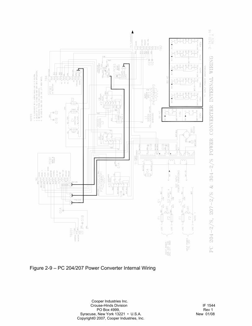
Figure 2-9 – PC 204/207 Power Converter Internal Wiring
Cooper Industries Inc. Crouse-Hinds Division IF 1544 PO Box 4999, Rev 1 Syracuse, New York 13221 • U.S.A. New 01/08 Copyright© 2007, Cooper Industries, Inc.
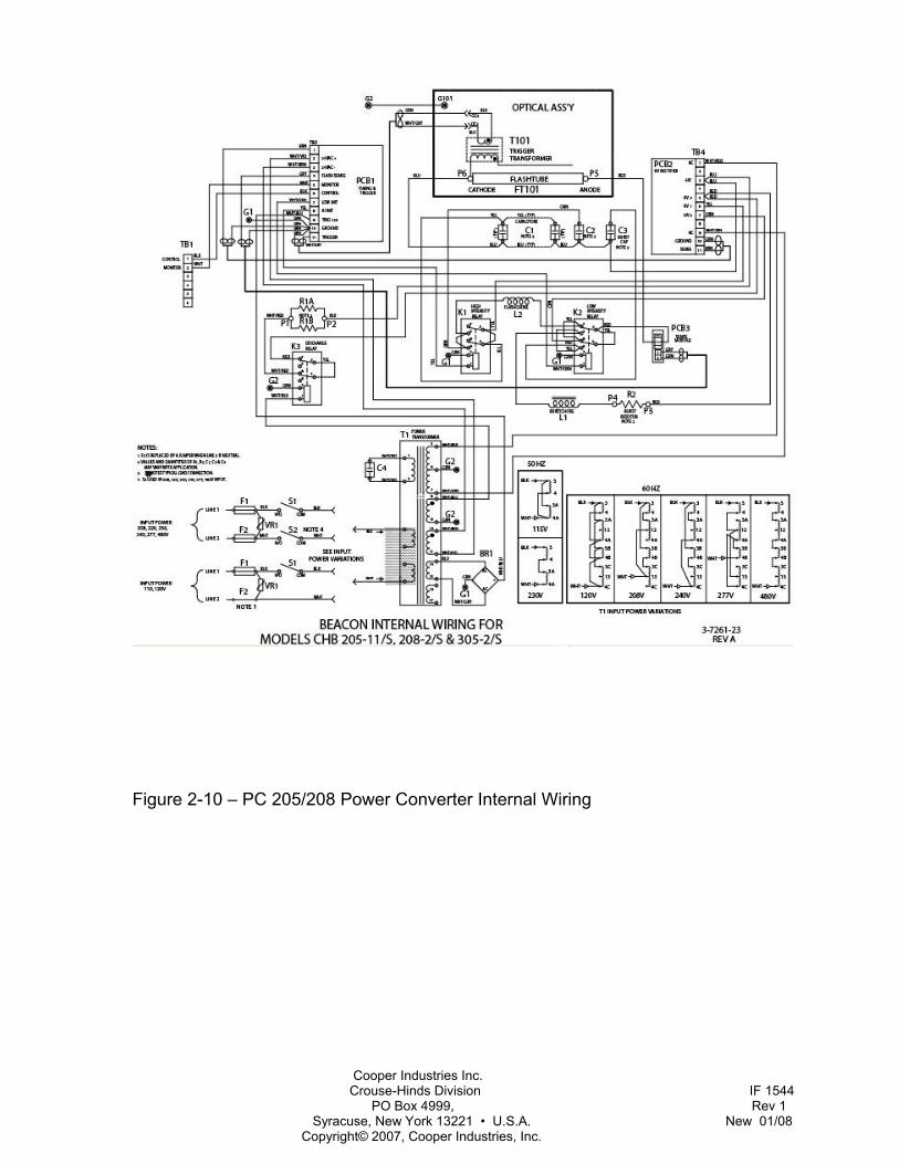
Figure 2-10 – PC 205/208 Power Converter Internal Wiring
Cooper Industries Inc. Crouse-Hinds Division IF 1544 PO Box 4999, Rev 1 Syracuse, New York 13221 • U.S.A. New 01/08 Copyright© 2007, Cooper Industries, Inc.
Section 3 — Maintenance and Troubleshooting
Safety HAZARD WARNING
Some procedures in this section may require making contact with electrical circuits. Read the warning on Page III.
Work safely, as follows:
• Remove rings and watches before opening the equipment.
• Shut off the equipment. • Remove the component or connect the
test instruments. • Replace the component. • Turn on the power and test the system. • Turn off the power and disconnect the
test equipment.
Preventive Maintenance Carry out the following inspection and cleaning procedures at least twice a year:
• Verify that moisture has not entered the equipment accidentally through gaskets or seals, or collected as condensation.
• Verify that all drain holes are clear. • Check terminal blocks and relays for
evidence of corrosion and electrical arcing. Clean or replace any component that shows evidence of high-voltage damage.
• Check flashtube connections for signs of pitting or arcing. Verify that anode and cathode connections are firmly tightened.
• Check all electrical connections for tightness and verify the absence of corrosion or electrical arcing.
• Clean the inside and outside surface of the glass with a non-abrasive glass cleaner.
Storage No special considerations are required for long-term storage of the equipment. Circuit boards, when not installed in the equipment, should be kept in antistatic bags or containers.
RFI Problems Radio frequency interference (RFI) can cause a light to flash intermittently, at the wrong rate, or at the wrong intensity. RFI can enter the light by way of any wire to or from the unit. For example:
• RFI on primary power wires could cause errors in flash rate and intensity.
• RFI on the control wire could cause a light to stay at night intensity.
• RFI on the PEC line could cause a light to stay at night intensity. RFI would not normally cause a light to stay at day/twilight intensity.
• Strong RFI could burn out PCB1 Timing and Trigger Board components.
The circuits are designed to reject or bypass RFI, but complete immunity cannot be guaranteed beforehand. It may be necessary after installation to add external filters or use other methods to reduce RFI entering the equipment.
Cooper Industries Inc. Crouse-Hinds Division IF 1544 PO Box 4999, Rev 1 Syracuse, New York 13221 • U.S.A. New 01/08 Copyright© 2007, Cooper Industries, Inc.
Component Testing The following procedures describe how to check most of the major electrical components. Always make resistance measurements with the power turned off. However, you must make voltage measurements with power applied. Thus, for your safety, perform all preliminary steps, such as connecting test leads or circuit jumpers, or disconnecting existing circuit connections, with the power turned off and storage capacitors discharged.
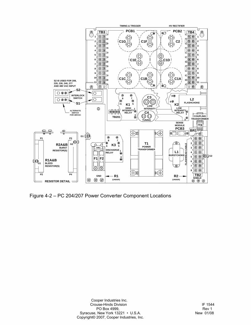
Refer to Figure 4-1, Figure 4-3, Figure , and Figure 4-4 for component layouts and locations.
Wiring and Cabling Wires or cables that move repeatedly will ultimately break. Ensure that all cables (the flashhead cable in particular) are securely fastened at short intervals to the structure or other supports.
Inspection Closely inspect the units and check the connections against the installation instructions. Also, a close inspection may reveal insulation breakdown, and overheated component, corrosion, loose connections, faulty relays, incorrect hookup, and so forth.
Capacitors Evaluate the condition of a capacitor with an analog volt-ohmmeter operating in the resistance mode. The following method assumes an instrument with a X100 resistance scale.
Place the meter leads across the terminals of an isolated (no electrical connections to other circuits) and fully discharged capacitor, and observe the subsequent needle movement.
If the capacitor is OK, the needle initially indicates zero ohms, but soon begins to
rise higher indicated values. A capacitor that is disconnected from other circuitry is defective if it does not exhibit this behavior. The length of time it takes the needle to reach the 1 megohm (about 65% of full-scale) reading is a measure of the capacitance. For example, the time is about 5 seconds for a 10 mfd capacitor; 10 seconds for a 20 mfd capacitor, and so forth.
Manually discharge the capacitor before repeating this measurement. This test may not detect a malfunction that occurs only at high voltage.
A bank of capacitors connected in parallel may be checked as a single unit. If a short circuit is indicated, the individual capacitors have to be disconnected and checked separately. A shorted capacitor is indicated if the resistance does not rise above zero after several seconds of measurement.
C1 — High Intensity Capacitor Bank The C1 main capacitor bank consists of several capacitors. Test these capacitors as described in Section Capacitors.
If the meter indicates a short circuit, you must isolate the individual capacitors and check them on at a time until you locate the defective capacitor.
C2 — Medium Intensity Capacitor Test C2 as described in Section Capacitors. Check the bank as a whole by placing the meter leads to the terminals of any C2 capacitor and pressing down the armature of the K3 discharge relay.
If a short circuit is indicated, you must isolate the capacitors and check them one at a time.
Cooper Industries Inc. Crouse-Hinds Division IF 1544 PO Box 4999, Rev 1 Syracuse, New York 13221 • U.S.A. New 01/08 Copyright© 2007, Cooper Industries, Inc.
C3 — Low Intensity Capacitor Test C3 as described in Section Capacitors. Remove all leads from one terminal cluster of this capacitor. The measured resistance across this capacitor should increase from zero to one megohm in approximately 1.5 seconds.
C4 — Tuning Capacitor Test C4 as described in Section Capacitors. Remove the lead from one terminal of this capacitor. The measured resistance across the capacitor should increase from zero to one megohm in approximately 1.5 seconds.
FT101 — Flashtube Visually inspect the flashtube for broken electrodes, cracked glass, and the solder connections of the pins. A darkened envelope does not necessarily mean the light output would be unacceptable. Before concluding that a faulty flashtube is responsible for an inadequate flash, first rule out other possible causes such as weak or absent discharge voltage or triggering pulses.
K1, K2 — Mode Relays, 24-volt DC Coil First remove PCB1. The resistance from TB3-8 and TB3-7 to TB3-10 or the chassis should be approximately 290 ohms.
K3 — Discharge Relay, 120 VAC Coil Disconnect one of the coil wires from the relay (terminal 1 or 2). The resistance across the relay coil should be approximately 290 ohms.
L1 — Burst Choke The measured resistance of this choke should be approximately 15 ohms.
L2 — Flash Choke The resistance of this coil should be zero ohms. An infinite reading indicates an open coil.
PCB1 — Timing and Trigger Board Replace this circuit board with one known to be in good condition. Be careful. For testing by substitution, the circuit board must have the same jumper configuration for JP12 through JP16 as the one being replaced in the unit. If the board is to remain in the unit, JP1 through JP11 must also be configured as the one being replaced.
R1A, R1B — Bleed Resistors The measured resistance of the discharge resistors in parallel should be 17,500 ohms.
PCB2 — HV Rectifier Board Replace this circuit board with one known to be in good condition.
R2A, R2B — Burst Resistors The measured resistance of the burst resistors in parallel should be 600 ohms.
T1 — Power Transformer Prepare to test this transformer by removing PCB1 and PCB2. Energize the unit and measure secondary winding voltages as described in the following table.
Test Points Voltage TB4-1 to TB4-9 900 - 1050 VAC TB3-9 to TB3-10 110 - 120 VAC TB3-2 to TB3-3 22- 26 VAC Across C4 550 to 600 VAC
If this AC voltage is substantially less than the specified minimum value, check the C4 tuning capacitor.
Cooper Industries Inc. Crouse-Hinds Division IF 1544 PO Box 4999, Rev 1 Syracuse, New York 13221 • U.S.A. New 01/08 Copyright© 2007, Cooper Industries, Inc.
PCB3 — Sense Module Replace this circuit board with one known to be in good condition.
T101 — Trigger Transformer The measured resistance of the flashtube cathode and trigger wire should be approximately 160 ohms. Check the potted secondary winding for evidence of high-voltage breakdown. Check the assembly screws for tightness and verify that the ferrite core is not fractured.
VR1 — Suppressor Assembly First remove one of the VR1 leads from the fuse block terminal. The resistance across VR1 on the x100K ohm scale should be infinite.
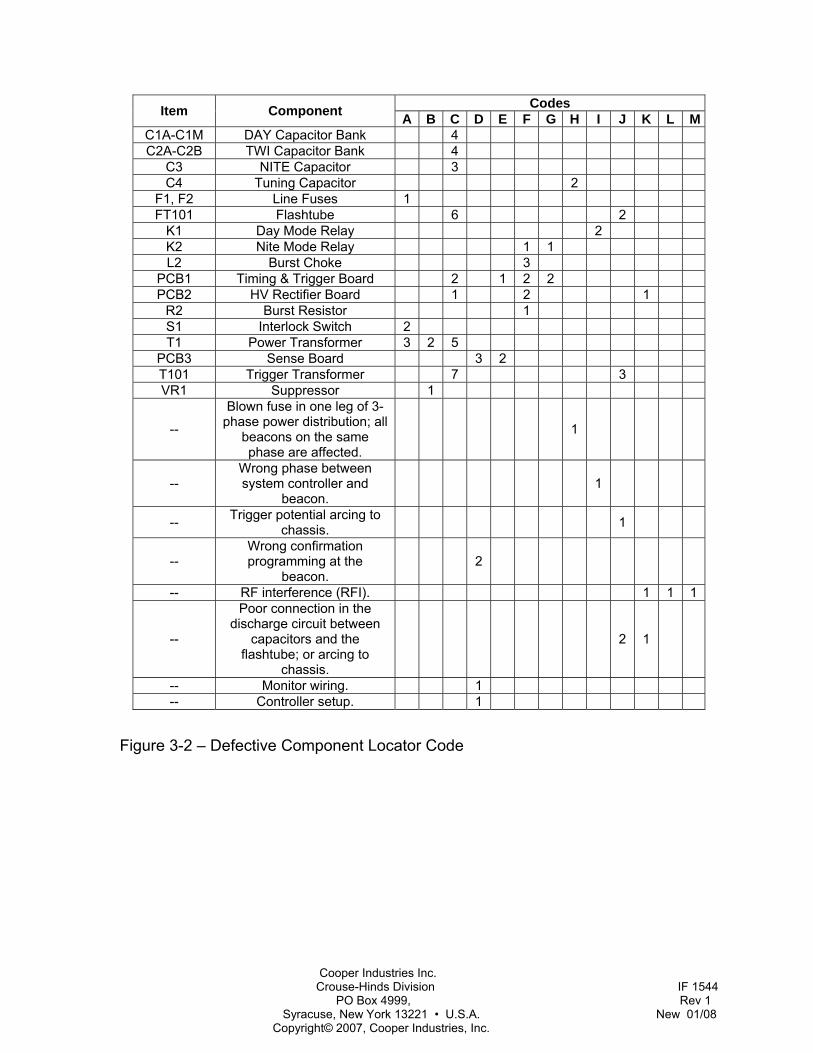
Troubleshooting Effective troubleshooting procedure, beginning with the observation of beacon behavior, often leads directly to a faulty component or other abnormal condition. Figure 3-1 – Major Troubleshooting Symptoms lists many of the symptoms that a malfunctioning beacon might exhibit. In Figure 3-2 – Defective Component Locator Code these symptoms are correlated with components, assemblies, or conditions that, if defective or abnormal, could cause the beacon to behave as observed.
For example, assume that the beacon does not flash at all but some of its circuits are still operating; that is, fuses are not blown, relays operate, and so forth. This behavior is symptom C in Table 3-2. Table 3-3 indicates that a defective timing and trigger board would most likely cause symptom C behavior. The next most likely cause would be a defective rectifier board. The third would be the NITE capacitor, and so forth. Each item in Table 3-3 is listed in the order of its likelihood of causing the failure.
Observe components carefully. Check for loose connections. Many times, components such as resistors and relays show signs of their failures. Resistors discolor when overheated. Relay contacts may become dirty, or pitted and corroded. Check relay armatures, to see if they function freely, by moving the armature by hand (with power off). Most components suspected of causing a problem can be checked by following the procedures in Section Component Testing.

Cooper Industries Inc. Crouse-Hinds Division IF 1544 PO Box 4999, Rev 1 Syracuse, New York 13221 • U.S.A. New 01/08 Copyright© 2007, Cooper Industries, Inc.
OBSERVED BEHAVIOR Flash Intensity Symptom
Code DAY TWI NITE Comments
A NO NO NO All circuits are dead. B NO NO NO Primary line fuse repeatedly blows. C NO NO NO Some circuits functioning. D OK OK OK No confirmation. E OK OK OK No DAY confirmation, but NITE OK. F OK OK NO G OK OK HIGH NITE too bright; ragged flash. H SKIPS OK OK I LOW OK HIGH J SKIPS SKIPS SKIPS K NO NO NO PCB2. L - - - Inconsistent and erratic flash. M NO NO NO No FAIL indication.
Figure 3-1 – Major Troubleshooting Symptoms
Cooper Industries Inc. Crouse-Hinds Division IF 1544 PO Box 4999, Rev 1 Syracuse, New York 13221 • U.S.A. New 01/08 Copyright© 2007, Cooper Industries, Inc.
Codes Item Component A B C D E F G H I J K L M
C1A-C1M DAY Capacitor Bank 4 C2A-C2B TWI Capacitor Bank 4
C3 NITE Capacitor 3 C4 Tuning Capacitor 2
F1, F2 Line Fuses 1 FT101 Flashtube 6 2
K1 Day Mode Relay 2 K2 Nite Mode Relay 1 1 L2 Burst Choke 3
PCB1 Timing & Trigger Board 2 1 2 2 PCB2 HV Rectifier Board 1 2 1
R2 Burst Resistor 1 S1 Interlock Switch 2 T1 Power Transformer 3 2 5
PCB3 Sense Board 3 2 T101 Trigger Transformer 7 3 VR1 Suppressor 1
--
Blown fuse in one leg of 3-phase power distribution; all
beacons on the same phase are affected.
1
-- Wrong phase between system controller and
beacon. 1
-- Trigger potential arcing to chassis. 1
-- Wrong confirmation programming at the
beacon. 2
-- RF interference (RFI). 1 1 1
--
Poor connection in the discharge circuit between
capacitors and the flashtube; or arcing to
chassis.
2 1
-- Monitor wiring. 1 -- Controller setup. 1
Figure 3-2 – Defective Component Locator Code
Cooper Industries Inc. Crouse-Hinds Division IF 1544 PO Box 4999, Rev 1 Syracuse, New York 13221 • U.S.A. New 01/08 Copyright© 2007, Cooper Industries, Inc.
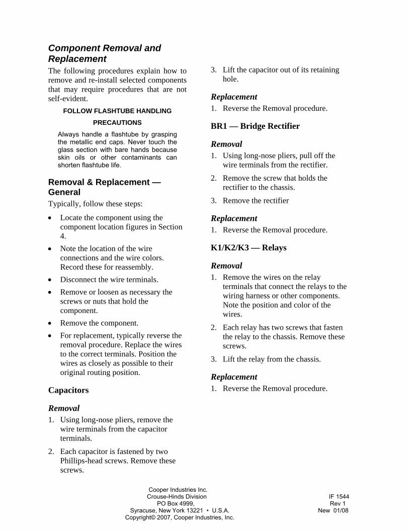
Component Removal and Replacement The following procedures explain how to remove and re-install selected components that may require procedures that are not self-evident.
FOLLOW FLASHTUBE HANDLING
PRECAUTIONS
Always handle a flashtube by grasping the metallic end caps. Never touch the glass section with bare hands because skin oils or other contaminants can shorten flashtube life.
Removal & Replacement — General Typically, follow these steps:
• Locate the component using the component location figures in Section 4.
• Note the location of the wire connections and the wire colors. Record these for reassembly.
• Disconnect the wire terminals. • Remove or loosen as necessary the
screws or nuts that hold the component.
• Remove the component. • For replacement, typically reverse the
removal procedure. Replace the wires to the correct terminals. Position the wires as closely as possible to their original routing position.
Capacitors
Removal 1. Using long-nose pliers, remove the
wire terminals from the capacitor terminals.
2. Each capacitor is fastened by two Phillips-head screws. Remove these screws.
3. Lift the capacitor out of its retaining hole.
Replacement 1. Reverse the Removal procedure.
BR1 — Bridge Rectifier
Removal 1. Using long-nose pliers, pull off the
wire terminals from the rectifier.
2. Remove the screw that holds the rectifier to the chassis.
3. Remove the rectifier
Replacement 1. Reverse the Removal procedure.
K1/K2/K3 — Relays
Removal 1. Remove the wires on the relay
terminals that connect the relays to the wiring harness or other components. Note the position and color of the wires.
2. Each relay has two screws that fasten the relay to the chassis. Remove these screws.
3. Lift the relay from the chassis.
Replacement 1. Reverse the Removal procedure.
Cooper Industries Inc. Crouse-Hinds Division IF 1544 PO Box 4999, Rev 1 Syracuse, New York 13221 • U.S.A. New 01/08 Copyright© 2007, Cooper Industries, Inc.
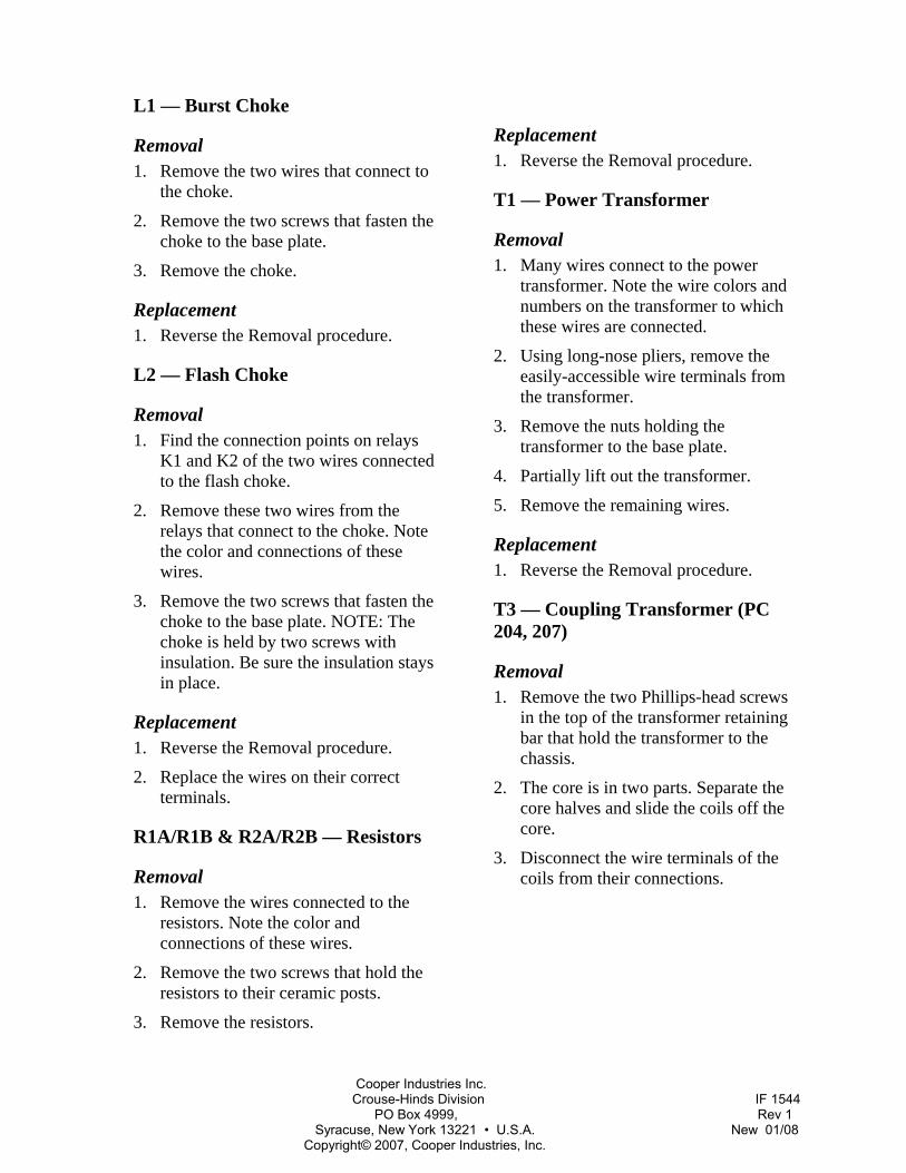
L1 — Burst Choke
Removal 1. Remove the two wires that connect to
the choke.
2. Remove the two screws that fasten the choke to the base plate.
3. Remove the choke.
Replacement 1. Reverse the Removal procedure.
L2 — Flash Choke
Removal 1. Find the connection points on relays
K1 and K2 of the two wires connected to the flash choke.
2. Remove these two wires from the relays that connect to the choke. Note the color and connections of these wires.
3. Remove the two screws that fasten the choke to the base plate. NOTE: The choke is held by two screws with insulation. Be sure the insulation stays in place.
Replacement 1. Reverse the Removal procedure.
2. Replace the wires on their correct terminals.
R1A/R1B & R2A/R2B — Resistors
Removal 1. Remove the wires connected to the
resistors. Note the color and connections of these wires.
2. Remove the two screws that hold the resistors to their ceramic posts.
3. Remove the resistors.
Replacement 1. Reverse the Removal procedure.
T1 — Power Transformer
Removal 1. Many wires connect to the power
transformer. Note the wire colors and numbers on the transformer to which these wires are connected.
2. Using long-nose pliers, remove the easily-accessible wire terminals from the transformer.
3. Remove the nuts holding the transformer to the base plate.
4. Partially lift out the transformer.
5. Remove the remaining wires.
Replacement 1. Reverse the Removal procedure.
T3 — Coupling Transformer (PC 204, 207)
Removal 1. Remove the two Phillips-head screws
in the top of the transformer retaining bar that hold the transformer to the chassis.
2. The core is in two parts. Separate the core halves and slide the coils off the core.
3. Disconnect the wire terminals of the coils from their connections.
Cooper Industries Inc. Crouse-Hinds Division IF 1544 PO Box 4999, Rev 1 Syracuse, New York 13221 • U.S.A. New 01/08 Copyright© 2007, Cooper Industries, Inc.
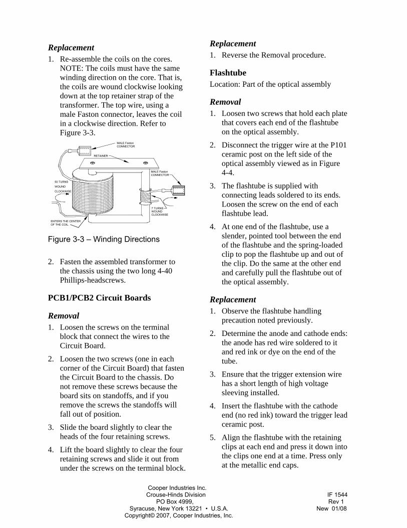
Replacement 1. Re-assemble the coils on the cores.
NOTE: The coils must have the same winding direction on the core. That is, the coils are wound clockwise looking down at the top retainer strap of the transformer. The top wire, using a male Faston connector, leaves the coil in a clockwise direction. Refer to Figure 3-3.
7 TURNSWOUNDCLOCKWISE
CLOCKWISE
WOUND
50 TURNS
ENTERS THE CENTEROF THE COIL.
MALE FastonCONNECTOR
RETAINER
MALE FastonCONNECTOR
Figure 3-3 – Winding Directions
2. Fasten the assembled transformer to the chassis using the two long 4-40 Phillips-headscrews.
PCB1/PCB2 Circuit Boards
Removal 1. Loosen the screws on the terminal
block that connect the wires to the Circuit Board.
2. Loosen the two screws (one in each corner of the Circuit Board) that fasten the Circuit Board to the chassis. Do not remove these screws because the board sits on standoffs, and if you remove the screws the standoffs will fall out of position.
3. Slide the board slightly to clear the heads of the four retaining screws.
4. Lift the board slightly to clear the four retaining screws and slide it out from under the screws on the terminal block.
Replacement 1. Reverse the Removal procedure.
Flashtube Location: Part of the optical assembly
Removal 1. Loosen two screws that hold each plate
that covers each end of the flashtube on the optical assembly.
2. Disconnect the trigger wire at the P101 ceramic post on the left side of the optical assembly viewed as in Figure 4-4.
3. The flashtube is supplied with connecting leads soldered to its ends. Loosen the screw on the end of each flashtube lead.
4. At one end of the flashtube, use a slender, pointed tool between the end of the flashtube and the spring-loaded clip to pop the flashtube up and out of the clip. Do the same at the other end and carefully pull the flashtube out of the optical assembly.
Replacement 1. Observe the flashtube handling
precaution noted previously.
2. Determine the anode and cathode ends: the anode has red wire soldered to it and red ink or dye on the end of the tube.
3. Ensure that the trigger extension wire has a short length of high voltage sleeving installed.
4. Insert the flashtube with the cathode end (no red ink) toward the trigger lead ceramic post.
5. Align the flashtube with the retaining clips at each end and press it down into the clips one end at a time. Press only at the metallic end caps.
Cooper Industries Inc. Crouse-Hinds Division IF 1544 PO Box 4999, Rev 1 Syracuse, New York 13221 • U.S.A. New 01/08 Copyright© 2007, Cooper Industries, Inc.
6. Attach the trigger wire (white insulation) at the ceramic post P101. Remove any excess wire and do not leave a tail extending from under the screw. Do not forcefully tighten the screw.
7. Attach the red anode wire to its connection directly above the tube mounting clip.
8. Attach the black cathode wire of the flashtube to the screw on the upper end of the plate on the left side of the optical assembly viewed as in Figure 4-4.
9. Reinstall each plate on each side of the flashtube and tighten the screws.
Flashtube Clips Location: Part of the optical assembly
Removal 1. Remove the flashtube as described in
Section Flashtube.
2. Remove two 8-32 screws from each flashtube clip plate.
Replacement 1. Reverse the Removal procedure. Be
sure that joining surfaces are clean. Tighten the screws firmly.
Trigger Transformer T101 Location: On the optical assembly
Removal 1. At the flashtube, remove the large
diameter white wire to the transformer secondary winding.
2. At a chassis ground screw remove the small wire to the transformer secondary winding.
3. Do not disconnect the primary winding wires. Remove the two 4-40 x 2-inch screws Phillips-head screws that hold the transformer assembly to the plate.
4. Note the orientation of the molded secondary winding with respect to fixed features on the plate because you must install its replacement with this same orientation.
5. Remove the outer half of the core and lift off the molded secondary winding. The primary winding remain hanging in place.
6. Remove the inner half of the core.
Replacement 1. Reassemble the primary and secondary
windings over the two halves of the core and attach the core to the bracket by means of the long screws. Do not overtighten.
2. Reattach the electrical wires. Refer to the electrical wiring diagram in Figure 2-11 to verify the connections.

Cooper Industries Inc. Crouse-Hinds Division IF 1544 PO Box 4999, Rev 1 Syracuse, New York 13221 • U.S.A. New 01/08 Copyright© 2007, Cooper Industries, Inc.
Section 4 – Recommended Spare & Replaceable Parts
Customer Service Customer Service: 1-866-764-5454
Facsimile: 315-477-5590
Shipping Address:
Cooper Crouse-Hinds P.O. Box 4999 Wolf & 7th North Street Syracuse, NY 13221
Ordering Parts To order spare or replacement parts, contact customer service at 1-866-764-5454.
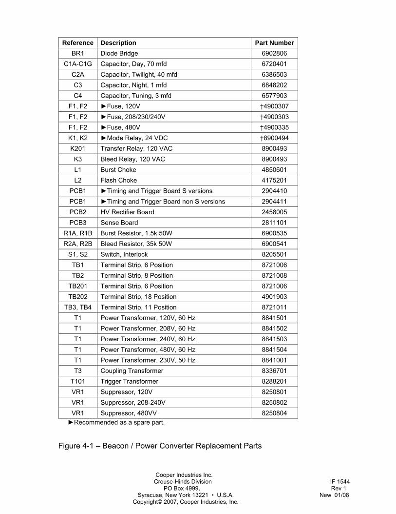
Beacon / Power Converter Parts Figure 4-1 Power Converter Major Replaceable Parts lists the major replaceable parts for the power converter.
Flashhead Parts Figure 4-4 lists the part numbers for the major replaceable parts
Cooper Industries Inc. Crouse-Hinds Division IF 1544 PO Box 4999, Rev 1 Syracuse, New York 13221 • U.S.A. New 01/08 Copyright© 2007, Cooper Industries, Inc.
Reference Description Part Number BR1 Diode Bridge 6902806
C1A-C1G Capacitor, Day, 70 mfd 6720401 C2A Capacitor, Twilight, 40 mfd 6386503 C3 Capacitor, Night, 1 mfd 6848202 C4 Capacitor, Tuning, 3 mfd 6577903
F1, F2 ►Fuse, 120V †4900307 F1, F2 ►Fuse, 208/230/240V †4900303 F1, F2 ►Fuse, 480V †4900335 K1, K2 ►Mode Relay, 24 VDC †8900494 K201 Transfer Relay, 120 VAC 8900493
K3 Bleed Relay, 120 VAC 8900493 L1 Burst Choke 4850601 L2 Flash Choke 4175201
PCB1 ►Timing and Trigger Board S versions 2904410 PCB1 ►Timing and Trigger Board non S versions 2904411 PCB2 HV Rectifier Board 2458005 PCB3 Sense Board 2811101
R1A, R1B Burst Resistor, 1.5k 50W 6900535 R2A, R2B Bleed Resistor, 35k 50W 6900541
S1, S2 Switch, Interlock 8205501 TB1 Terminal Strip, 6 Position 8721006 TB2 Terminal Strip, 8 Position 8721008
TB201 Terminal Strip, 6 Position 8721006 TB202 Terminal Strip, 18 Position 4901903
TB3, TB4 Terminal Strip, 11 Position 8721011 T1 Power Transformer, 120V, 60 Hz 8841501 T1 Power Transformer, 208V, 60 Hz 8841502 T1 Power Transformer, 240V, 60 Hz 8841503 T1 Power Transformer, 480V, 60 Hz 8841504 T1 Power Transformer, 230V, 50 Hz 8841001 T3 Coupling Transformer 8336701
T101 Trigger Transformer 8288201 VR1 Suppressor, 120V 8250801 VR1 Suppressor, 208-240V 8250802 VR1 Suppressor, 480VV 8250804
►Recommended as a spare part.
Figure 4-1 – Beacon / Power Converter Replacement Parts
Cooper Industries Inc. Crouse-Hinds Division IF 1544 PO Box 4999, Rev 1 Syracuse, New York 13221 • U.S.A. New 01/08 Copyright© 2007, Cooper Industries, Inc.
P2
G1
P1
RESISTOR DETAIL
P4
RESISTOR(S)
RESISTOR(S)BLEEDR1A&B
BURSTG2
P3
R2A&B
F1 F2
VR1
INTERLOCKSWITCH
ALTERNATE
FOR 480VACSWITCH
(UNDER)R1GND
7
5
1
3
8
6 K3DISCHARGERELAY
T3
TRANSFORMERCOUPLING
1
2
3
11
6
10
9
7
8
4
5
1
2
11
6
10
9
8
7
4
5
3
C1G
C1E C1D
C1F
L2FLASHCHOKEK2
LOWINTENSITY
RELAY
8
6
3
1
C3
C4
LOWINTENSITY
TUNINGTB201
T1POWER
TRANSFORMER
(UNDER)R2
BURSTCHOKEL1
BR1
SENSEMODULE
FLA
SHH
EAD
CA
BLE
2
3
4
5
6
7
8
1
TB2
TB4TB3
SHIELD
G2
G1
PCB2HV RECTIFIERTIMING & TRIGGER
PCB1
S1
S2
S2 IS USED FOR 208, 220, 230, 240, 277 AND 480 VAC INPUT
PCB3
6 5
3
1
8 7
K1HIGH
INTENSITYRELAY
C1C C1B
C2
C1A
Figure 4-2 – PC 204/207 Power Converter Component Locations
Cooper Industries Inc. Crouse-Hinds Division IF 1544 PO Box 4999, Rev 1 Syracuse, New York 13221 • U.S.A. New 01/08 Copyright© 2007, Cooper Industries, Inc.
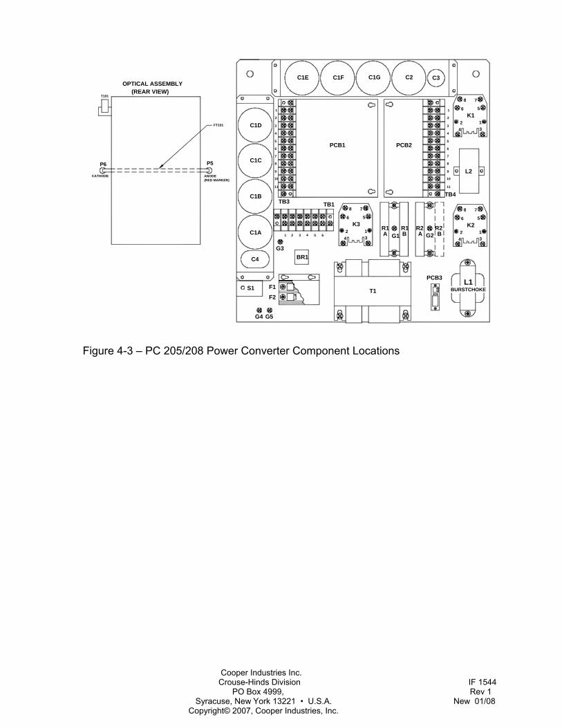
G4 G5
FT101
(RED MARKER)ANODECATHODE
T101(REAR VIEW)
OPTICAL ASSEMBLY
R2
8
S1
C4
F2
F1
G3
C1A
C1BTB3
1 32 4
11
10
9
G1
T1
65
TB1
AR1
BR1
C1D
C1C
3
7
6
5
4
2
1
C1E
PCB1 PCB2
C1F C1G C2
8
PCB3
TB4
G2
9
10
11
L2
3
4
5
6
7
1
2 K1
C3
BR1
P5P6
R2A B
1234
56
78
2 1K2
6 5
8 7
34
1234
K36 5
8 7
BURSTCHOKEL1
Figure 4-3 – PC 205/208 Power Converter Component Locations
Cooper Industries Inc. Crouse-Hinds Division IF 1544 PO Box 4999, Rev 1 Syracuse, New York 13221 • U.S.A. New 01/08 Copyright© 2007, Cooper Industries, Inc.
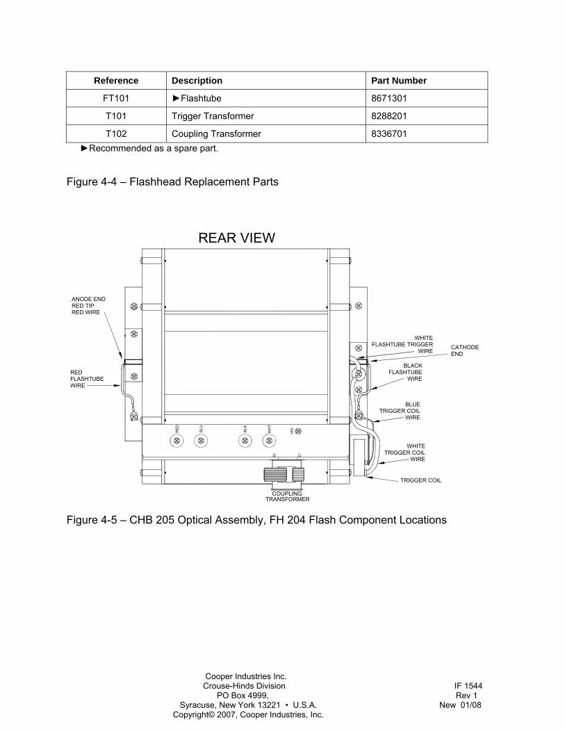
Reference Description Part Number
FT101 ►Flashtube 8671301
T101 Trigger Transformer 8288201
T102 Coupling Transformer 8336701 ►Recommended as a spare part.
Figure 4-4 – Flashhead Replacement Parts
RE
D
BLK
WH
T
BLU
COUPLINGTRANSFORMER
VIO
REAR VIEW
REDFLASHTUBEWIRE
BLACKFLASHTUBE
WIRE
WHITEFLASHTUBE TRIGGER
WIRE
TRIGGER COILBLUE
WIRE
TRIGGER COILWIRE
WHITE
TRIGGER COIL
ANODE ENDRED TIPRED WIRE
CATHODEEND
Figure 4-5 – CHB 205 Optical Assembly, FH 204 Flash Component Locations
Cooper Industries Inc. Crouse-Hinds Division IF 1544 PO Box 4999, Rev 1 Syracuse, New York 13221 • U.S.A. New 01/08 Copyright© 2007, Cooper Industries, Inc.
Returning Equipment – Return Material Authorization (RMA)
If a product purchased from Cooper Crouse-Hinds must be returned for any reason, please follow the procedure below:
NOTE: An RMA number must be requested from Cooper Crouse-Hinds prior to shipment of any product. No returned product will be processed without an RMA number. This number will be the only reference necessary for returning and getting information on the product’s progress.
1. To initiate an RMA, customers should call the Cooper Crouse-Hinds Customer Service Center at (866-764-5454) to receive technical assistance and a case number. The following information is required before a case number can be generated:
• Site Name/Number / FCC Registration number/ Call Letters or Airport Designator
• Site Owner (provide all that apply – owner, agent or subcontractor)
- Contractor Name
- Contractor Company
• Point of Contact Information: Name, Phone Number, Email Address, Fax Number and Cell Phone (or alternate phone number)
• Product’s Serial Number
• Product’s Model Number or part number
• Case Number (if previously given)
• Reason for call, with a full description of the reported issue
2. The case number will then serve as a precursor to receiving an RMA number if it is determined that the product or equipment should be returned. To expedite the RMA process, please provide:
• Return shipping method
• Purchase Order (if non-warranty repair)
• Shipping Address
• Bill To Address
• Any additional information to assist in resolving the issue or problem
3. A P.O. is required in advance for the replacement of product that may be under warranty. Flash will then, at its discretion issue a credit once the validity of the warranty has been determined.
4. A purchase order (P.O.) is also required in advance for all non-warranty repairs. NOTE: the purchase order is required prior to the issuance of the RMA number.
• If the P.O. number is available at the time of the call, an RMA number will be issued and the customer must then fax or email the P.O. with the RMA number as the reference, to ensure prompt processing.
Cooper Industries Inc. Crouse-Hinds Division IF 1544 PO Box 4999, Rev 1 Syracuse, New York 13221 • U.S.A. New 01/08 Copyright© 2007, Cooper Industries, Inc.
• If the P.O. number is NOT available at the time of the call, a Case Number will be given to the customer and should be referenced on the P.O. when faxed or emailed to RMA Rep.
• Cooper Crouse-Hinds will then, at its discretion repair or replace the defective product and return the product to the customer based on the shipping method selected.
• The customer may purchase a new product before sending in the existing product for repair. If Cooper Crouse-Hinds determines the existing product is still covered under warranty a credit will be issued to the customer for the new product.
5. After receiving the Cooper Crouse-Hinds RMA number, please adhere to the following packaging guidelines:
• All returned products should be packaged in a way to prevent damage in transit. Adequate packing should be provided taking into account the method of shipment. Cooper Crouse-Hinds will not be responsible for damaged items if product is not returned in appropriate packaging.
6. All packages should clearly display the RMA number on the outside of all RMA shipping containers. RMA products (exact items and quantity) should be returned to:
Cooper Crouse-Hinds Attn: RMA #XXX
1700 Blue Hills Drive, NE Roanoke, VA 24012
7. All RMA numbers:
• Are valid for 15 business days. Products received after may result in extra screening and delays.
• Must have all required information provided before a RMA number to be assigned.
Return to Stock Policy • Parts can be returned within 90 days of ship date and will be subject to a 20% restocking
fee. Product must: - Be in the original packaging
- Not be damaged
• After 90 days no parts can be returned
Cooper Industries Inc. Crouse-Hinds Division IF 1544 PO Box 4999, Rev 1 Syracuse, New York 13221 • U.S.A. New 01/08 Copyright© 2007, Cooper Industries, Inc.
Appendix 1 – Programming the Timing and Trigger Board
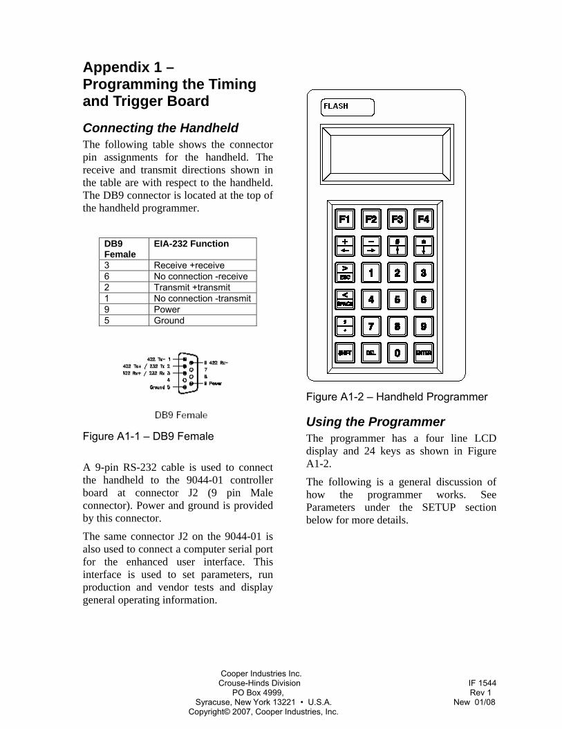
Connecting the Handheld The following table shows the connector pin assignments for the handheld. The receive and transmit directions shown in the table are with respect to the handheld. The DB9 connector is located at the top of the handheld programmer.
DB9 Female
EIA-232 Function
3 Receive +receive 6 No connection -receive 2 Transmit +transmit 1 No connection -transmit 9 Power 5 Ground
Figure A1-1 – DB9 Female
A 9-pin RS-232 cable is used to connect the handheld to the 9044-01 controller board at connector J2 (9 pin Male connector). Power and ground is provided by this connector.
The same connector J2 on the 9044-01 is also used to connect a computer serial port for the enhanced user interface. This interface is used to set parameters, run production and vendor tests and display general operating information.
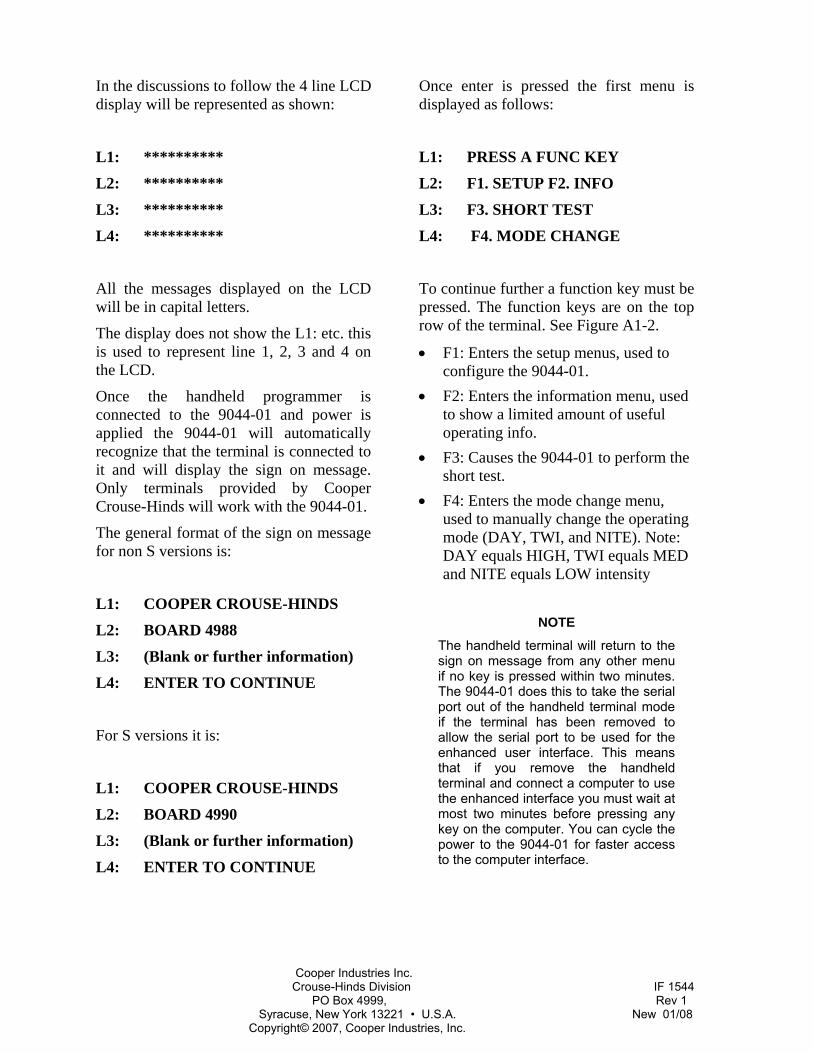
Figure A1-2 – Handheld Programmer
Using the Programmer The programmer has a four line LCD display and 24 keys as shown in Figure A1-2.
The following is a general discussion of how the programmer works. See Parameters under the SETUP section below for more details.
Cooper Industries Inc. Crouse-Hinds Division IF 1544 PO Box 4999, Rev 1 Syracuse, New York 13221 • U.S.A. New 01/08 Copyright© 2007, Cooper Industries, Inc.
In the discussions to follow the 4 line LCD display will be represented as shown:
L1: **********
L2: **********
L3: **********
L4: **********
All the messages displayed on the LCD will be in capital letters.
The display does not show the L1: etc. this is used to represent line 1, 2, 3 and 4 on the LCD.
Once the handheld programmer is connected to the 9044-01 and power is applied the 9044-01 will automatically recognize that the terminal is connected to it and will display the sign on message. Only terminals provided by Cooper Crouse-Hinds will work with the 9044-01.
The general format of the sign on message for non S versions is:
L1: COOPER CROUSE-HINDS
L2: BOARD 4988
L3: (Blank or further information)
L4: ENTER TO CONTINUE
For S versions it is:
L1: COOPER CROUSE-HINDS
L2: BOARD 4990
L3: (Blank or further information)
L4: ENTER TO CONTINUE
Once enter is pressed the first menu is displayed as follows:
L1: PRESS A FUNC KEY
L2: F1. SETUP F2. INFO
L3: F3. SHORT TEST
L4: F4. MODE CHANGE
To continue further a function key must be pressed. The function keys are on the top row of the terminal. See Figure A1-2.
• F1: Enters the setup menus, used to configure the 9044-01.
• F2: Enters the information menu, used to show a limited amount of useful operating info.
• F3: Causes the 9044-01 to perform the short test.
• F4: Enters the mode change menu, used to manually change the operating mode (DAY, TWI, and NITE). Note: DAY equals HIGH, TWI equals MED and NITE equals LOW intensity
NOTE
The handheld terminal will return to the sign on message from any other menu if no key is pressed within two minutes. The 9044-01 does this to take the serial port out of the handheld terminal mode if the terminal has been removed to allow the serial port to be used for the enhanced user interface. This means that if you remove the handheld terminal and connect a computer to use the enhanced interface you must wait at most two minutes before pressing any key on the computer. You can cycle the power to the 9044-01 for faster access to the computer interface.
Cooper Industries Inc. Crouse-Hinds Division IF 1544 PO Box 4999, Rev 1 Syracuse, New York 13221 • U.S.A. New 01/08 Copyright© 2007, Cooper Industries, Inc.
SETUP for Non S Versions The setup menu has the following format:
L1: SETUP
L2: 0-1-1
L3:
L4: OK NEXT BACK EXIT
The first line displays the current menu. The second line displays the current setup. The numbers correspond to the selected parameters. The third line is blank. The fourth line displays what functions the keys F1 thru F4 will perform if pressed; the words are spaced to be over the corresponding function key. So, to move to the next menu you would press F2 (NEXT).
• F1: OK- is used to enter data. • F2: NEXT- moves to the next item. • F3: BACK- moves to the previous
item. • F4: EXIT- exits the setup menu.
SETUP for S Versions The setup menu has the following format:
L1: SETUP
L2: DASH 10 T 1 B 1
L3:
L4: OK NEXT BACK EXIT
The first line displays the current menu. The second line displays the current setup. The numbers correspond to the dash number tier and beacon selected. The third line is blank. The fourth line displays what functions the keys F1 thru F4 will perform if pressed; the words are spaced to be over
the corresponding function key. So, to move to the next menu you would press F2 (NEXT).
• F1: OK- is used to enter data. • F2: NEXT- moves to the next item. • F3: BACK- moves to the previous
item. • F4: EXIT- exits the setup menu.
Parameters for Non S Versions Pressing the NEXT or BACK function key from the SETUP menu takes you to the parameters. The general format is:
L1: SETUP
L2: SYSTEM
L3: 0- Std. 1- Air. 2- Cat
L4: OK NEXT BACK EXIT
The currently selected option will have the cursor under it. For example:
“0-Std 1-Air 2-Cat” shows that the currently selected option for the parameter is one (1) which in this case means Standard system.
If the board to be configured is not in the Standard mode press 1 and press F1 (OK).
NOTE
Even if your board is configured for Standard mode you will need to press 1 and F1 to change the tier and beacon number.
Cooper Industries Inc. Crouse-Hinds Division IF 1544 PO Box 4999, Rev 1 Syracuse, New York 13221 • U.S.A. New 01/08 Copyright© 2007, Cooper Industries, Inc.
The display will change to:
L1: SETUP
L2: TIER # 1
L3: Enter TIER #
L4: OK NEXT BACK EXIT
Press the number keys to select the tier number you wish this board to be and then press F1 (OK). The Tier number displayed will change. The display will change to:
L1: SETUP
L2: BEACON # 1
L3: Enter Beacon #
L4: OK NEXT BACK EXIT
Press the number keys to select the beacon number you wish this board to be and then press F1 (OK). The Beacon number displayed will change. When complete, press NEXT. Be sure to write the numbers on the white space provided on the board.
If setting up a catenary system press 2 and F1 (OK).
NOTE
Even if your board is configured for Catenary mode you will need to press 2 and F1 to change the position.
The display will change to:
L1: SETUP
L2: CAT TIER
L3: 0-BOT. 1-MID. 2-TOP
L4: OK NEXT BACK EXIT
Press the number keys to select the catenary tier you wish this board to be and then press F1 (OK).
To change the Flash rate press NEXT until the LCD shows:
L1: SETUP
L2: FPM 1-60 2-30
L3: 3-20 4-100 5-120
L4: OK NEXT BACK EXIT
NOTE
Valid flash rates are 40fpm and 60 fpm for standard and catenary systems, respectively.
Then press the number corresponding to the desired flash rate and press F1 (OK)
Parameters for S Versions Pressing the NEXT or BACK function key from the SETUP menu takes you to the parameters. The general format is:
L1: SETUP
L2: DASH # 10
L3: Enter Dash #
L4: OK NEXT BACK EXIT
To change the dash number, enter a number and press F1 OK. Press NEXT to continue. Note: Dash numbers should only be programmed by trained Cooper Crouse-Hinds personnel or under the direction of same.

Cooper Industries Inc. Crouse-Hinds Division IF 1544 PO Box 4999, Rev 1 Syracuse, New York 13221 • U.S.A. New 01/08 Copyright© 2007, Cooper Industries, Inc.
The display will change to:
L1: SETUP
L2: TIER # 1
L3: Enter TIER #
L4: OK NEXT BACK EXIT
Press the number keys to select the tier number you wish this board to be and then press F1 (OK). The tier number displayed will change. When complete, press NEXT or BACK.
The display will change to:
L1: SETUP
L2: BEACON # 1
L3: Enter BEACON #
L4: OK NEXT BACK EXIT
Press the number keys to select the beacon number you wish this board to be and then press F1 (OK). The beacon number displayed will change. When you are done press NEXT, BACK or EXIT.
INFO The info menu has the following format for non S version:
L1: INFO
L2: BOARD 4988
L3:
L4: NEXT BACK EXIT
The info menu has the following format for S version:
L1: INFO
L2: BOARD 4990
L3:
L4: NEXT BACK EXIT
This menu is used to show a limited amount of information about the current 9044-01 operation and configuration.
The first line displays the current menu. The second and third lines display board information. The fourth line displays what functions the keys F2 thru F4 will perform if pressed; the words are spaced to be over the corresponding function key. So, to move to the next item you would press F2 (NEXT).
• F2: NEXT- moves to the next item. • F3: BACK- moves to the previous
item. • F4: EXIT- exits the setup menu. Items
like energy, trigger voltage, flash rate and operating mode are displayed.
MODE CHANGE The mode change menu has the following format:
L1: MODE CONTROL
L2: CURRENT DAY
L3:
L4: DAY TWI NITE EXIT

Cooper Industries Inc. Crouse-Hinds Division IF 1544 PO Box 4999, Rev 1 Syracuse, New York 13221 • U.S.A. New 01/08 Copyright© 2007, Cooper Industries, Inc.
• F1: DAY- Changes the mode to DAY. • F2: TWI- Changes the mode to TWI. • F3: NITE- Changes the mode to NITE. • F4: EXIT- exits the mode change
menu and returns the mode to automatic.
This menu item is used to manually change the operating modes and functions just like the test jumpers on the board.

Cooper Industries Inc. Crouse-Hinds Division IF 1544 PO Box 4999, Rev 1 Syracuse, New York 13221 • U.S.A. New 01/08 Copyright© 2007, Cooper Industries, Inc.
Appendix 2 - CHB 204SPB and 207SPB Primary Backup
Operation The 204SPB and 207SPB provide an extra trigger for the operation of a secondary flashhead as shown in Figure A2-1. The power converter operates the primary flashhead until a failure is detected. Once in alarm, the power converter will switch trigger to the backup flashhead and continue to operate normally.
Once in backup mode, the power converter will send a “Backup Mode” alarm to the CHC 121 Controller. This is intended to alert the operator that the primary has failed and the unit is operating in backup mode. In the event that both the primary and backup flashhead fail, the power converter will send a normal “Strobe Failure” alarm to the controller.
Installation The 204SPB and 207SPB are installed as described in Section 2 with the additional mounting and wiring of the backup flashhead. The internal wiring is shown in Figure A2-2 for reference.
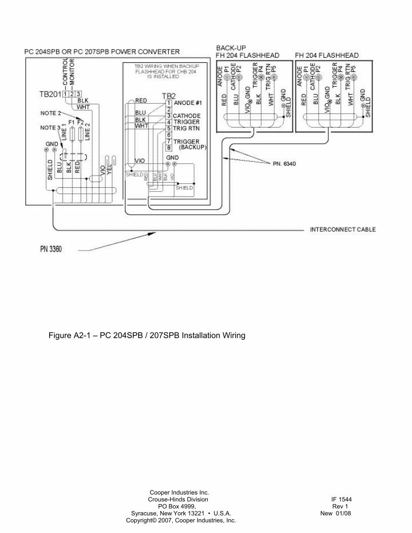
Cooper Industries Inc. Crouse-Hinds Division IF 1544 PO Box 4999, Rev 1 Syracuse, New York 13221 • U.S.A. New 01/08 Copyright© 2007, Cooper Industries, Inc.
Figure A2-1 – PC 204SPB / 207SPB Installation Wiring
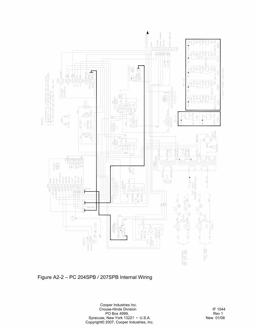
Cooper Industries Inc. Crouse-Hinds Division IF 1544 PO Box 4999, Rev 1 Syracuse, New York 13221 • U.S.A. New 01/08 Copyright© 2007, Cooper Industries, Inc.
Figure A2-2 – PC 204SPB / 207SPB Internal Wiring
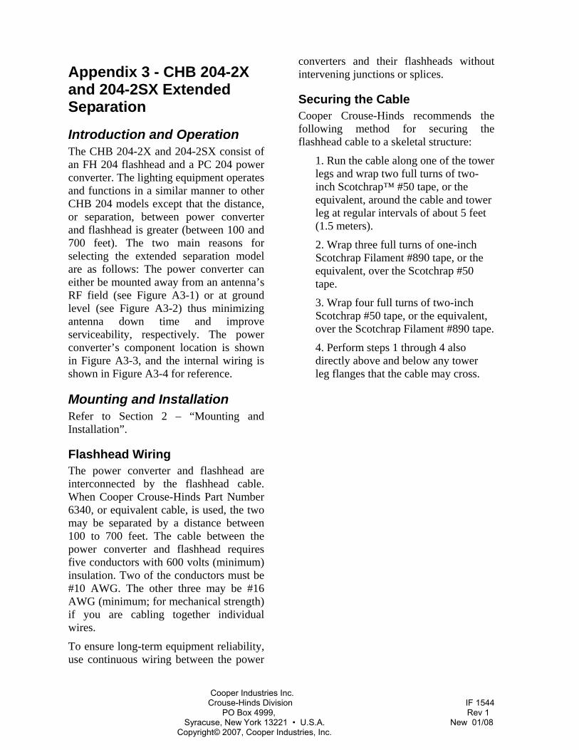
Cooper Industries Inc. Crouse-Hinds Division IF 1544 PO Box 4999, Rev 1 Syracuse, New York 13221 • U.S.A. New 01/08 Copyright© 2007, Cooper Industries, Inc.
Appendix 3 - CHB 204-2X and 204-2SX Extended Separation
Introduction and Operation The CHB 204-2X and 204-2SX consist of an FH 204 flashhead and a PC 204 power converter. The lighting equipment operates and functions in a similar manner to other CHB 204 models except that the distance, or separation, between power converter and flashhead is greater (between 100 and 700 feet). The two main reasons for selecting the extended separation model are as follows: The power converter can either be mounted away from an antenna’s RF field (see Figure A3-1) or at ground level (see Figure A3-2) thus minimizing antenna down time and improve serviceability, respectively. The power converter’s component location is shown in Figure A3-3, and the internal wiring is shown in Figure A3-4 for reference.
Mounting and Installation Refer to Section 2 – “Mounting and Installation”.
Flashhead Wiring The power converter and flashhead are interconnected by the flashhead cable. When Cooper Crouse-Hinds Part Number 6340, or equivalent cable, is used, the two may be separated by a distance between 100 to 700 feet. The cable between the power converter and flashhead requires five conductors with 600 volts (minimum) insulation. Two of the conductors must be #10 AWG. The other three may be #16 AWG (minimum; for mechanical strength) if you are cabling together individual wires.
To ensure long-term equipment reliability, use continuous wiring between the power
converters and their flashheads without intervening junctions or splices.
Securing the Cable Cooper Crouse-Hinds recommends the following method for securing the flashhead cable to a skeletal structure:
1. Run the cable along one of the tower legs and wrap two full turns of two-inch Scotchrap™ #50 tape, or the equivalent, around the cable and tower leg at regular intervals of about 5 feet (1.5 meters).
2. Wrap three full turns of one-inch Scotchrap Filament #890 tape, or the equivalent, over the Scotchrap #50 tape.
3. Wrap four full turns of two-inch Scotchrap #50 tape, or the equivalent, over the Scotchrap Filament #890 tape.
4. Perform steps 1 through 4 also directly above and below any tower leg flanges that the cable may cross.
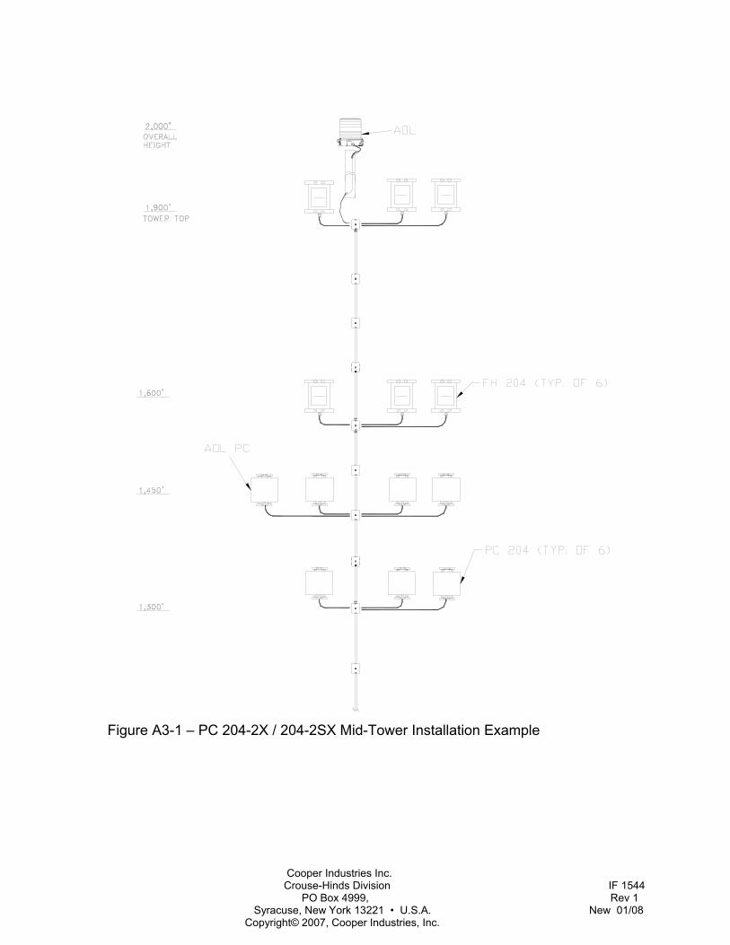
Cooper Industries Inc. Crouse-Hinds Division IF 1544 PO Box 4999, Rev 1 Syracuse, New York 13221 • U.S.A. New 01/08 Copyright© 2007, Cooper Industries, Inc.
Figure A3-1 – PC 204-2X / 204-2SX Mid-Tower Installation Example
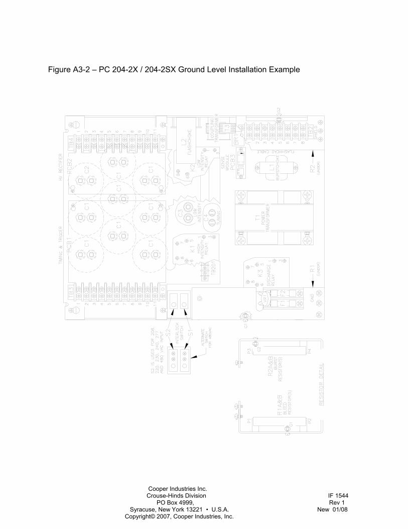
Cooper Industries Inc. Crouse-Hinds Division IF 1544 PO Box 4999, Rev 1 Syracuse, New York 13221 • U.S.A. New 01/08 Copyright© 2007, Cooper Industries, Inc.
Figure A3-2 – PC 204-2X / 204-2SX Ground Level Installation Example
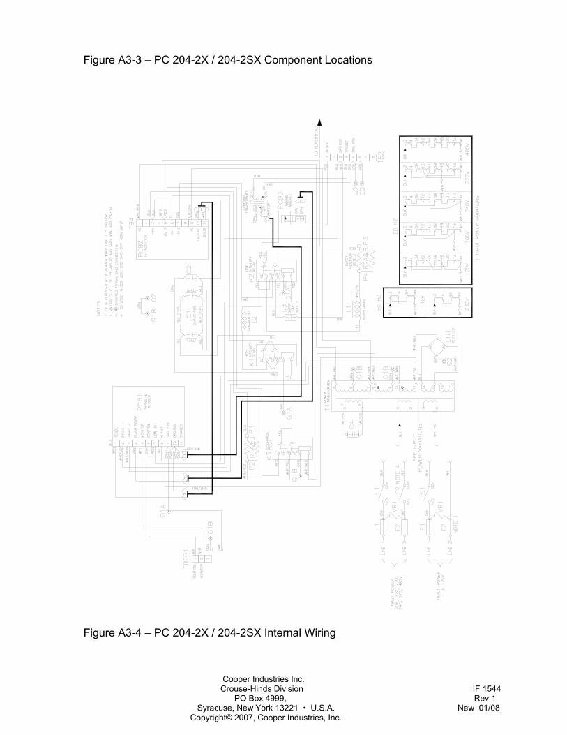
Cooper Industries Inc. Crouse-Hinds Division IF 1544 PO Box 4999, Rev 1 Syracuse, New York 13221 • U.S.A. New 01/08 Copyright© 2007, Cooper Industries, Inc.
Figure A3-3 – PC 204-2X / 204-2SX Component Locations
Figure A3-4 – PC 204-2X / 204-2SX Internal Wiring
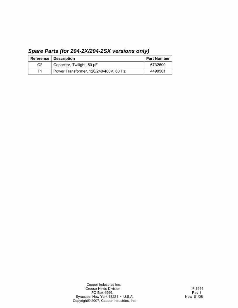
Cooper Industries Inc. Crouse-Hinds Division IF 1544 PO Box 4999, Rev 1 Syracuse, New York 13221 • U.S.A. New 01/08 Copyright© 2007, Cooper Industries, Inc.
Spare Parts (for 204-2X/204-2SX versions only) Reference Description Part Number
C2 Capacitor, Twilight, 50 µF 6732600 T1 Power Transformer, 120/240/480V, 60 Hz 4499501