Embed Size (px)
Citation preview

CHASSIS
1. MAJOR CHANGES.................................2. MOUNTING LOCATIONS (CHASSIS).....3. CHASSIS COMPONENT LAYOUT.........4. SUB FRAME AND STEERING GEAR BOX LAYOUT........................................5. FRONT SUSPENSION COMPONENT LAYOUT.................................................6. REAR SUSPENSION COMPONENT LAYOUT.................................................7. BRAKE SYSTEM AND ESP SYSTEM LAYOUT.................................................8. STEERING SYSTEM LAYOUT..............
GENERAL INSTRUCTIONS
1. GUIDELINES FOR SERVICE WORKS....2. JACK-UP POINTS..................................3. STANDARD BOLTS SPECIFICATIONS..
SPECIAL TOOLS AND EQUIPMENT
1. SPECIAL TOOLS...................................
222526
27
38
10
12
14
16
1820


01-30000-00
1. MAJOR CHANGES1) Gear Shift Lever and Cable (Manual Transaxle)
Gear shift lever bracket
Gear shift lever assembly
Old New
The gear shift lever bracket has been changed to adopt the premium console.
Gear shift cable assembly
Old New
The connection and socket to lever has been changed.

01-4
2) Steering Wheel Angle Sensor
SWAS: Steering Wheel Angle Sensor
Old New
The sensor has been changed due to newly adopted steering wheel heating system.The location of sensor connector and the pin arrangement of connector have been changed.
1.2.
Sensor connector Sensor connector

01-50000-00
3) Steering Wheel Heating SystemSteering wheel heating unit
Old New
The steering wheel heated wire and the heating unit are installed in the steering wheel assembly.
Lower main switch cluster
Old
New
The steering wheel heating switch has been added on the lower main switch cluster.
Specifications▶
Description Specification
Power consumption Below 95W
Rated voltage 12V
Operating voltage 9V~16V
Rated current 6±2.0A
Steering wheel heating unit
Steering wheel heating switch
01-6
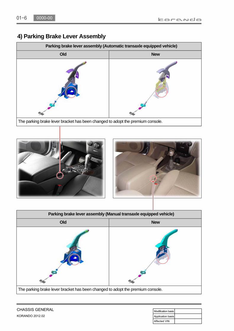
4) Parking Brake Lever AssemblyParking brake lever assembly (Automatic transaxle equipped vehicle)
Old New
The parking brake lever bracket has been changed to adopt the premium console.
Parking brake lever assembly (Manual transaxle equipped vehicle)
Old New
The parking brake lever bracket has been changed to adopt the premium console.


01-8
Fuse for vehicle with EPS
The vehicle with EPS has EPS fuse (80A) mounted to the positive (+) terminal of the battery not in the fuse box.
EPS unit
The ECU controls the electric power steering system depending on the driving conditions, based on the signals from the torque and angle sensor.
HECU (Hydraulic & Electronic Control Unit)
HECU for ABS HECU for EPS
The HECU (Hydraulic & Electronic Control Unit) determines the slip conditions of vehicle wheels by calculating each wheel's speed and the increment/decrement of speed based on the information detected by the sensors, and controls the pumping and boosting/reducing/keeping pressure by operating the valve and motor of HECU.
2. MOUNTING LOCATIONS (CHASSIS)
Moto
HU (Hydraulic Unit) ECU (Electronic Control Unit)
Moto
HU (Hydraulic Unit)
ECU (Electronic Control Unit)
Motor angle (8P)
Motor power (3P)
Torque angle sensor (8P)
Battery (2P)Connector to vehicle (8P)
Fuse for EPS
Steering wheel angle sensor (SWAS)
The steering wheel angle sensor is mounted between the steering column and the steering column shaft. It is commonly used by the ESP (Electronic Stability Program) system. And it receives signals of the steering wheel angle sensor from the ESP HECU (Hydraulic & Electronic Control Unit).

01-90000-00
G-sensor(4WD, ABS)
For the vehicle with the ABS, a speed difference between the wheels is not noticeable as all the wheels are slipping during abrupt braking. Therefore, the vehicle needs the speed information from other sensors other than the wheel speed sensor. The longitudinal acceleration sensor (G-sensor) is used for this case. It controls the ABS by using the signals from the sensor during abrupt braking and acceleration.
TCU unit
The transmission control unit (TCU) is installed under the driver seat, and controls the transmission. The TCU is operated by the ignition power supply and receives and processes the following information from the inner sensors through CAN buses.
E-coupling unit
The E-coupling unit is a control unit which determines the magnetic force by considering CAN signals (wheel speed, engine torque, pedal opening, ABS/ESP CAN signals, etc.) from other ECUs.
TGS Lever assembly
The TGS communicates with TCU (Transmission Control Unit), ECU, ESP HECU and instrument cluster to let the driver select the desired transmission gear and to maintain the desired driving condition. Also, the tip switch is installed on the lever knob and the steering wheel so that the driver select the gear manually when the shift lever is in "M".
Sensor cluster
The sensor cluster is linked to the sensors on the unit board and CAN interface. And they are housed in one case and mounted to the body.

01-10
3. CHASSIS COMPONENT LAYOUT
M11 6-speed A/T assembly
M11 6-speed automatic transmission is available as 4WD- and 2WD-type, and provides 6 speeds for forward travel and 1 reverse travel. It is also equipped with the torque converter with inner lock-up clutch and electronically controlled solenoid which controls all hydraulic functions.
PTU (Power Transfer Unit)
The PTU is a device that transfers the power generated from the engine to the rear axle through propeller shaft and E-coupling by changing the power flow direction by 90° in the front wheel drive type 4WD vehicle.
Rear axle assembly
The rear axle installed in this car is a removable axle, called IRDA (Independent Rear Differential Axle). The rear differential carrier is installed directly on the sub frame, and there is an independent suspension that allows each wheel on the same axle to move vertically independently of each other with the universal joint and the slip joint.
E-coupling control unit (E-Coupling ECU)
The E-coupling unit is a control unit which determines the magnetic force by considering CAN signals (wheel speed, engine torque, pedal opening, ABS/ESP CAN signals, etc.) from other ECUs.
Inhibitor switch
Torque converterOil pan
E-coupling side Rear axle side
Propeller shaft
1) 4WD Vehicle With Automatic Transmission

01-110000-00
M6LF1 manual transmission
M6LF1 manual transmission is a model modified from the one that used in other vehicle so that it can be applied to FF (Front engine-Front wheel driving) type vehicle, and has an axle in one piece. The engine torque and gear ratio of this transmission have been optimized to maximize driving performance. It provides 6 speeds for forward travel and 1 reverse travel.
Clutch assembly
M6LF1 manual transmission is a model modified from the one that used in other vehicle so that it can be applied to FF (Front engine-Front wheel driving) type vehicle, and has an axle in one piece. The engine torque and gear ratio of this transmission have been optimized to maximize driving performance. It provides 6 speeds for forward travel and 1 reverse travel.
The 2WD vehicle with manual transmission is a front wheel drive type vehicle that doesn't have PTU, propeller shaft, E-coupling and rear axle which are applied to 4WD vehicle. Its under structure is very simple.
Manual gear selector lever
Transmission side Control shaft assembly
Transaxle side Concentric slave assembly
Pressure plate
2) 2WD Vehicle With Manual Transmission
Clutch disc

01-12
Front sub frame with HPS type steering gear box assembly
The front sub frame consists of 4 body bush mountings and 2 transmission bush mountings which reduce the vibration from the powertrain and road, and also control the torque. And the frame is equipped with hydraulic pressure pipe of the HPS type steering gear box.
4. SUB FRAME AND STEERING GEAR BOX LAYOUT
Front sub frame with EPS type steering gear box assembly
This kind of front sub frame system has the same mounting structure with the frame with HPS. But the EPS type steering gear box has no hydraulic pressure pipe since it is driven by the electric motor.
Rear side
Front side
HPS type steering gear box assembly
Front sub frame assembly
Rear side
Front side
EPS type steering gear box assembly
Front sub frame assembly

01-130000-00
Rear sub frame assembly for 4WD
The rear sub frame for 4WD vehicle consists of 4 body (bush) mountings and 2 axle (direct) mountings which reduce the vibration from the powertrain and road, and also control the torque.
Rear side
Front side
Body mounting
Rear sub frame assembly for 2WD
The rear sub frame for 2WD vehicle functions in the same way as the one for 4WD vehicle, but the structure is different from the one for 4WD. It consists of 4 body (bush) mountings.
Body mounting
Body mounting Body mounting
Axle mounting
Front sideBody mounting Body mounting
Rear side Body mountingBody mounting
01-14
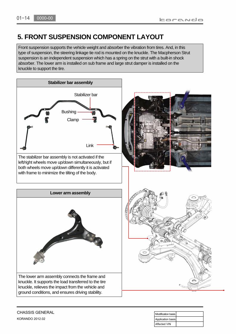
Stabilizer bar assembly
The stabilizer bar assembly is not activated if the left/right wheels move up/down simultaneously, but if both wheels move up/down differently it is activated with frame to minimize the tilting of the body.
5. FRONT SUSPENSION COMPONENT LAYOUTFront suspension supports the vehicle weight and absorber the vibration from tires. And, in this type of suspension, the steering linkage tie rod is mounted on the knuckle. The Macpherson Strut suspension is an independent suspension which has a spring on the strut with a built-in shock absorber. The lower arm is installed on sub frame and large strut damper is installed on the knuckle to support the tire.
Lower arm assembly
The lower arm assembly connects the frame and knuckle. It supports the load transferred to the tire knuckle, relieves the impact from the vehicle and ground conditions, and ensures driving stability.
Stabilizer bar
Bushing
Clamp
Link

01-150000-00
Front coil spring assembly
The coil spring is made by winding solid steel rod to form the coil shape. Its energy absorption rate per weight is higher than that of the leaf spring and it allows to absorb small vibration properly resulted in keeping the ride comforts. Therefore, it's difficult to make an effect on vibration damping because there is not any friction between coils.
Coil spring
Shock absorber assembly

01-16
6. REAR SUSPENSION COMPONENT LAYOUTMulti-link type suspension is the independent suspension. It provides good ride comfort and drivability by reducing the coil spring weight. Also, it increases the space for passenger compartment by lowering the floor.This type of suspension consists of multiple links such as trailing arm, upper arm, lower arm and track rod.
Shock absorber assembly
This vehicle uses the gas shock absorber. This relieves the vertical vibrations of vehicle to provide ride comforts, prevents the spring break, enhances drivability, and extends the life span of steering components.
Upper arm assembly
Upper arm is installed between knuckle and sub frame and controls the lateral load and vehicle height.
Trailing arm assembly
Trailing arm is installed between knuckle and vehicle body and controls the front and rear load.
Track rod assembly
Track rod is installed between knuckle and rear sub frame and controls and compensates the lateral load.
01-170000-00
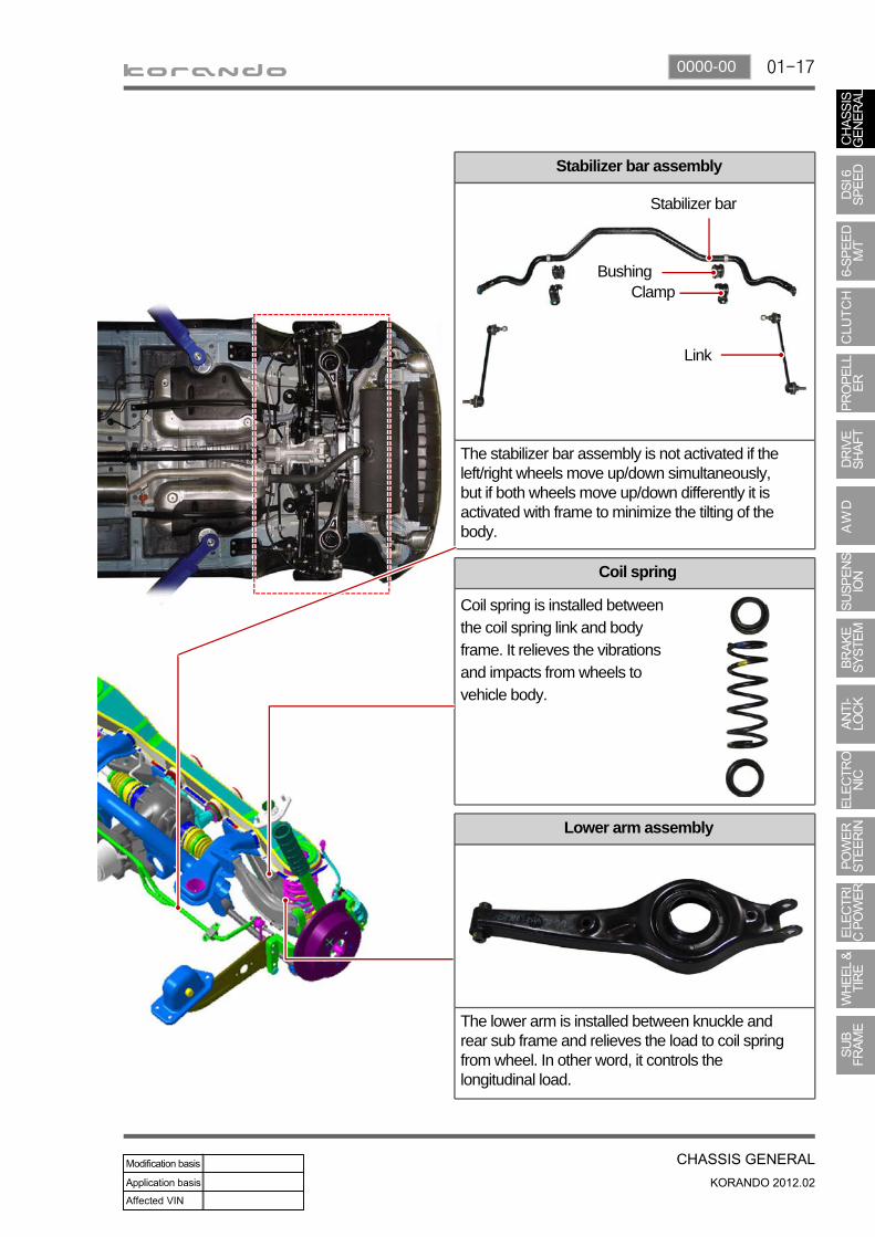
Stabilizer bar assembly
The stabilizer bar assembly is not activated if the left/right wheels move up/down simultaneously, but if both wheels move up/down differently it is activated with frame to minimize the tilting of the body.
Coil spring
Coil spring is installed between the coil spring link and body frame. It relieves the vibrations and impacts from wheels to vehicle body.
Lower arm assembly
The lower arm is installed between knuckle and rear sub frame and relieves the load to coil spring from wheel. In other word, it controls the longitudinal load.
Stabilizer bar
BushingClamp
Link
01-18
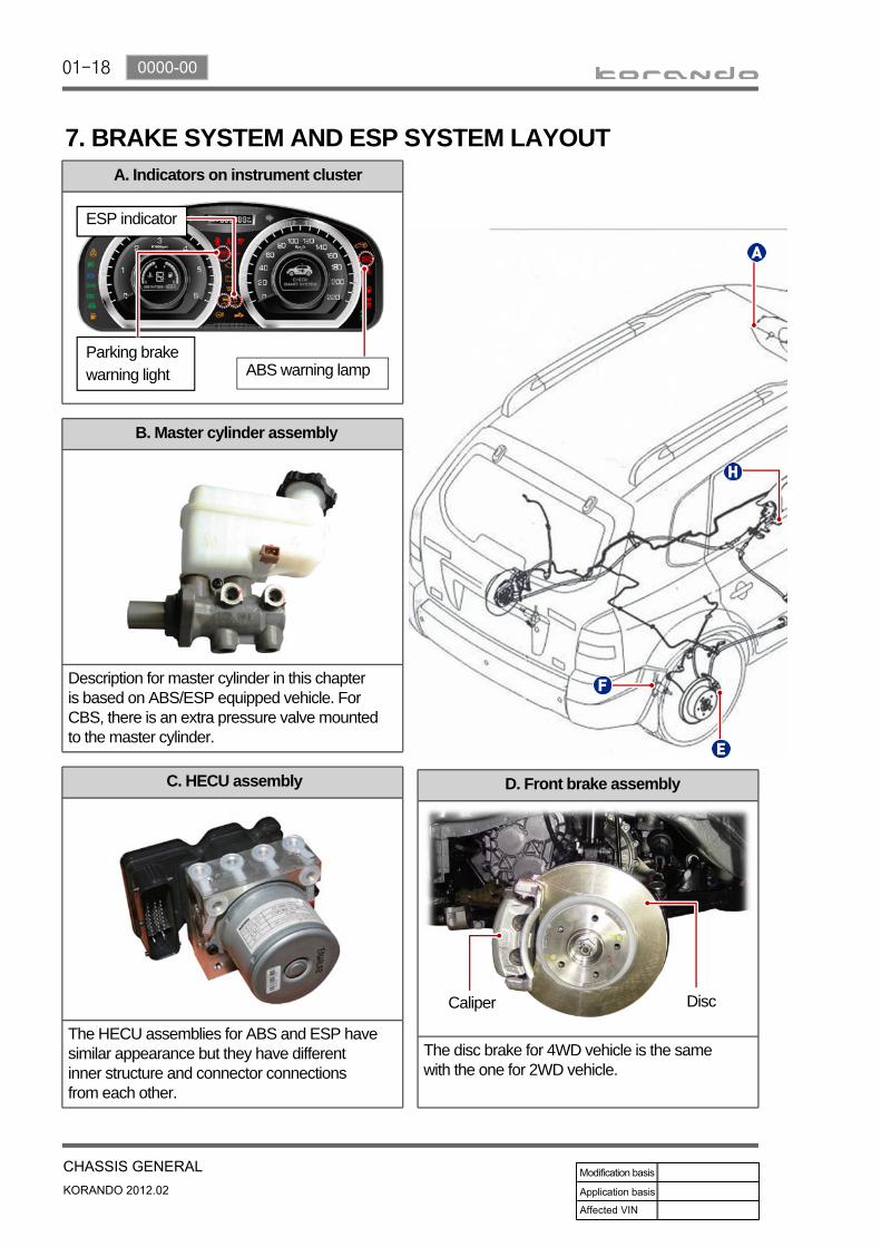
A. Indicators on instrument cluster
C. HECU assembly
The HECU assemblies for ABS and ESP have similar appearance but they have different inner structure and connector connections from each other.
D. Front brake assembly
The disc brake for 4WD vehicle is the same with the one for 2WD vehicle.
7. BRAKE SYSTEM AND ESP SYSTEM LAYOUT
B. Master cylinder assembly
Description for master cylinder in this chapter is based on ABS/ESP equipped vehicle. For CBS, there is an extra pressure valve mounted to the master cylinder.
Caliper Disc
Parking brake warning light ABS warning lamp
ESP indicator

01-190000-00
H. Parking brake
M/T A/T
The parking brake is the mechanical device to hold the vehicle. When pulling up the lever, the parking brake cable between the lever and the rear drum brake trailing shoe pulls the parking brake lining to contact to drum.
E. Rear brake assembly
The disc brake for 4WD vehicle has the same structure with the one for 2WD vehicle, but the appearance and knuckle shape is different from each other.
Caliper
G. Brake pedal
Disc
F. Parking brake
4WD and 2WD Front side
2WD Rear side
The wheel speed sensor for 4WD has the same structure and mounting location with the one for 2WD vehicle. But the rear side wheel speed sensor for 2WD vehicle has different sensor appearance and mounting status because the knuckle shape is different from the 4WD vehicle.

01-20
Steering gear box assembly
The steering gear box assembly consists of power cylinder and control valve. The power cylinder has a cylinder, piston and piston rod. The control valve directs the oil to one end face of the piston to enhance the steering force. There is a safety check valve which lets the driver steer manually when there is a malfunction in the hydraulic circuit.
8. STEERING SYSTEM LAYOUT1) HPS (Hydraulic Power Steering)The hydraulic pump is a vane type pump and consists of the flow control valve and pressure relief valve.
The oil reservoir sends the oil to the power steering pump and receives the oil from the power steering gear.
There is a shock absorber which is folded in the axial direction when the vehicle is crashed and a ignition switch assembly on the column shaft.
The lower shaft minimizes the torque change using a CV joint which has constant angular speed.
Tie rod endSteering cylinder Gear box Tie rod endHydraulic pipe
Column shaft
Lower shaft
Steering wheel assembly
Hydraulic pipe & hose

01-210000-00
ECU
The ECU controls the electric power steering system depending on the driving conditions, based on the signals from the torque and angle sensor.
2) EPS (Electric Power Steering)Fuse
The vehicle with EPS has EPS fuse (80A) mounted to the positive (+) terminal of the battery, and this fuse supplies power to the EPS unit directly..
Steering gear box assembly
When the driver turns the steering wheel, a torque is generated and the torque sensor and the steering angle sensor in the EPS system detect the rotation of the steering column to run the electric motor. At this time, the worm gear connected to the motor drives the helical gear mounted to the steering column to generate the assist torque for the steering column. This allows the driver to operate the steering wheel easier.
ECU
Tie rod end Tie rod endGear boxSteering cylinder
Steering wheel assembly
BLAC motor
Lower shaft
Column shaft
Colum shaft assembly
The column shaft assembly consists of BLAC motor, ECU, torque and angle sensors. The electric power steering (EPS) system uses the electric motor to assist the steering force. It functions independently regardless of whether the engine is running or not, unlike the existing hydraulic power steering.The lower shafts functions in the same way as the hydraulic type.

01-22
1. GUIDELINES FOR SERVICE WORKS1) For SafetyTo perform the service works easily ans safely, the service technicians must keep the proper working procedures and rules.This manual provides the useful instructions to the service technicians so that they can perform the servive works with standard working process, skills, tips in time.Please read this manual and follow the instructions carefully.
Signal words such as “WARNING”, “CAUTION” and “NOTE” have special meanings.
indicates information to assist maintenance and instructions.
However, above references and cautions cannot be inclusive measures, so should have habits of paying attentions and cautions based on common senses.
indicates a potentially hazardous situation which, if not avoided, may result in minor or moderate injury or property damage.
indicates a potentially hazardous situation which, if not avoided, could result in death or serious injury.

01-230000-00
3) General InstructionsBefore lifting up the vehicle with a lift, correctly support the lifting points.When using a jack, park the vehicle on a level ground and place the wheel chocks under the tires. Position the jack under the frame and lift up the vehicle and then support with chassis stand before service work.Make sure to disconnect the negative (-) cable from the battery to prevent any damage to electric systems.If you have to work on vehicle, cover the seats and floor with protection covers to avoid any damage and contamination.Brake fluid and anti-freeze can damage the painted surface of body. So carefully handle them during service work.To improve the efficiency of service work, use only recommended and specified tools.Use only Ssangyong genuine spare parts.Never reuse the cotter pin, gasket, O-ring, oil seal, lock washer and self-locking nut. Replace them with new ones. If reused, normal functions cannot be maintained.Store the disassembled parts as a set based on disassembly order and unit.Pay particular attention not to miss or mix the fasteners.If necessary, especially for inspection, clean the removed parts completely.Apply the oil or grease on the running and sliding surfeces before installation. Use the specified sealant and gasket to prevent leakage if necessary.Tighten the fasteners to the specified tightening torque.As a final stage of service work, check if the serviced system is working properly and the problem has been eliminated clearly.
(1)(2)
(3)
(4)
(5)
(6)(7)(8)
(9)(10)(11)(12)
(13)(14)
Remove the engine and transaxle as a set.
Manual transaxle: Transaxle can be separated after removing the front module (sub frame, engine and transaxle).Automatic transaxle: Transaxle can be separated after removing the sub frame.
-
-
2) EquipmentKorando is FF (Front Engine Front Drive) type vehicle, and engine and powertrain system are integrated into a module. Therefore, 2-post lift and general equipment are necessary when working on the engine and transmission.Major equipment: Engine and transmission jack, Engine stand, Engine crane, Transmission jack, Engine hanger
-
-
Engine stand
Engine crane

01-24
4) Basic Inspection(1) Horn operation
Listen for the horn sound when pressing the horn pad on the steering wheel.-
(2) Brake operationCheck if there is any abnormal noise, unusually long braking distance, or uneven braking force. If the brake warning lamp does not go out even after starting the engien or are flashing during driving, have the brake system checked immediately.Check the brake pipes and hoses for connection, oil leak, crack or interference after changing the position of tires. When replacing the tires, check the brake disc for surface condition and wear.Check the parking brake cable and brake operation. Shorten the checking interval if the parking brake is used frequently.
-
-
-
(3) Exhaust system Be aware to any changes in sound or smell from the exhaust system. These may be caused by leak or overheat. Have the exhaust system checked and repaired immediately.Inspect the exhaust system including catalytic converter. Inspect all the components and body frame near the exhaust system.
-
-
(4) TiresUnusual vibration of the steering wheel and seats or pulling to one side on the straight and level roads may indicates the uneven tire inflation pressure or poor wheel balance.
-
(5) Steering and suspension system Inspect the front and rear suspension and the steering system for damage, looseness or missing parts, signs of wear or lack of lubrication. Inspect the power steering line and the hoses for connection, leak, crack and chafing. Inspect the drive axle boot and seals for damage, tear or leak. Replace or repair the system if necessary.
-
(6) Engine oil Check the oil level when the engine is still warm and add the specified engine oil if necessary.-
(7) Coolant Check the coolant level in the coolant reservoir, coolant conditions (contamination, foreign material), and hoses for damage and leak. Replace or add the Ssangyong genuine coolant, if needed.
-
(8) Engine drive belt Check all drive belts on the engine for wear, crack and looseness. Retighten or replace the belt, if needed.
-

01-250000-00
2. JACK-UP POINTSStand jack-up points and installation status (front side)▶
Jack-up points for 2-post lift
Stand jack-up points and installation status (rear side)
Stand jack-up points and installation status (front side)
Jack-up points for 2-post lift
Installation status
Installation status
01-26
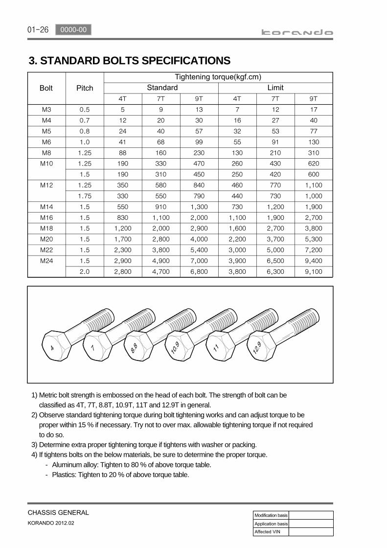
3. STANDARD BOLTS SPECIFICATIONS
Metric bolt strength is embossed on the head of each bolt. The strength of bolt can be classified as 4T, 7T, 8.8T, 10.9T, 11T and 12.9T in general.Observe standard tightening torque during bolt tightening works and can adjust torque to be proper within 15 % if necessary. Try not to over max. allowable tightening torque if not required to do so.Determine extra proper tightening torque if tightens with washer or packing.If tightens bolts on the below materials, be sure to determine the proper torque.
1)
2)
3)4)
Aluminum alloy: Tighten to 80 % of above torque table.Plastics: Tighten to 20 % of above torque table.
--
01-270000-00
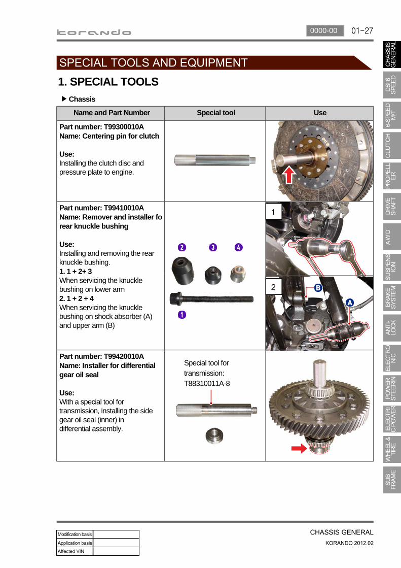
1. SPECIAL TOOLSChassis▶
1
2
Special tool for transmission:T88310011A-8
Name and Part Number Special tool Use
Part number: T99300010AName: Centering pin for clutch
Use:Installing the clutch disc and pressure plate to engine.
Part number: T99410010AName: Remover and installer forear knuckle bushing
Use:Installing and removing the rear knuckle bushing.1. 1 + 2+ 3When servicing the knuckle bushing on lower arm2. 1 + 2 + 4When servicing the knuckle bushing on shock absorber (A) and upper arm (B)
Part number: T99420010AName: Installer for differential gear oil seal
Use:With a special tool for transmission, installing the side gear oil seal (inner) in differential assembly.

01-28
1) Equipment for Engine Assembly
Name and Part Number Equipment Use
Name: Engine and transmission jack
Use:Heavy duty jack for removing the engine and transmission as a set
Name: Engine stand (1 ton or more)
Use:Fixing the removed engine or engine and transmission (transaxle).
Name: Engine crane (1 ton or more)
Use:Moving the engine module (including transaxle) to working area or on engine stand.

01-290000-00
2) Special Tools for Manual Transaxle
T88310011A-9
1
2
Name and Part Number Tool Use
Part number: T88310011A-16Name: Special tool set for manual transaxle
This tool set is designated for manual transaxle (WM6F1) and consists of 16
Part number T88310011A-1Name: Installer for gear
Use:With the bearing support (T88310011A-9), installing the gear and hub on each output shaft.
Part number T88310011A-2Name: Installer for oil seal andtaper roller bearing
Use:Installing the taper roller bearing (1) on input shaft and oil seal (2) on clutch housing.
01-30
1
2
3
T88310011A-8
T88310011A-8
T88310011A-8
T88310011A-8
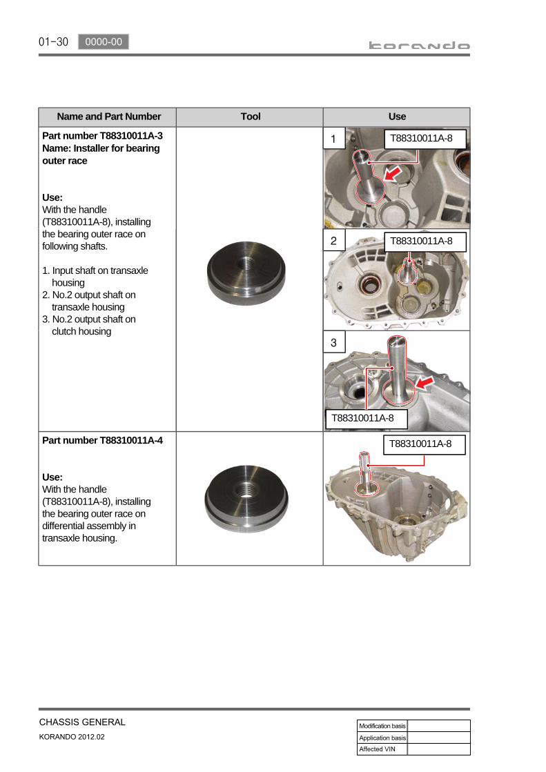
Name and Part Number Tool Use
Part number T88310011A-3Name: Installer for bearing outer race
Use:With the handle (T88310011A-8), installing the bearing outer race on following shafts.
1. Input shaft on transaxle housing2. No.2 output shaft on transaxle housing3. No.2 output shaft on clutch housing
Part number T88310011A-4
Use:With the handle (T88310011A-8), installing the bearing outer race on differential assembly in transaxle housing.

01-310000-00
1
2
T88310011A-8
T88310011A-8
T88310011A-8
T88310011A-8
Name and Part Number Tool Use
Part number T88310011A-5Name: Installer for bearing outer race
Use:With the handle (T88310011A-8), installing the bearing outer race on following shafts.
1. No.1 output shaft on clutch housing2. No.1 output shaft on transaxle housing
Part number T88310011A-6Name: Installer for bearing outer race
Use:With the handle (T88310011A-8), installing the front bearing outer race on differential assembly in clutch housing.
Part number T88310011A-7Name: Installer for bearing outer race
Use:With the handle (T88310011A-8), installing the bearing outer race on outer shaft in clutch housing.

01-32
T88310011A-9
Name and Part Number Tool Use
Part number T88310011A-8Name: Handle
Use:Installing the bearing outer race.
Part number T88310011A-9Name: Bearing support
Use:Supporting the shaft when installing the gear, hub bearing or input shaft bearing.
Part number T88310011A-10Name: Installer for taper rollerbearing
Use:With the bearing support (T88310011A-9), installing the taper roller bearing on each output shaft.
Part number T88310011A-11Name: Installer for taper rollerbearing on No.1 output shaft
Use:With the bearing support (T88310011A-9), installing the taper roller bearing No.1 output shaft (1st gear side).
01-330000-00
T88310011A-9
T88310011A-9
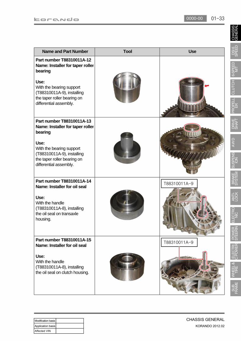
Name and Part Number Tool Use
Part number T88310011A-12Name: Installer for taper rollerbearing
Use:With the bearing support (T88310011A-9), installing the taper roller bearing on differential assembly.
Part number T88310011A-13Name: Installer for taper rollerbearing
Use:With the bearing support (T88310011A-9), installing the taper roller bearing on differential assembly.
Part number T88310011A-14Name: Installer for oil seal
Use:With the handle (T88310011A-8), installing the oil seal on transaxle housing.
Part number T88310011A-15Name: Installer for oil seal
Use:With the handle (T88310011A-8), installing the oil seal on clutch housing.
01-34
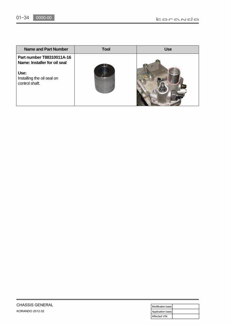
Name and Part Number Tool Use
Part number T88310011A-16Name: Installer for oil seal
Use:Installing the oil seal on control shaft.