Embed Size (px)
Citation preview
CHARMEC
stage 7
triennial report1 July 2012–30 June 2015
review1 July 1995–30 June 2012
plans1 July 2015–30 June 2018
Chalmers Railway Mechanics – a NUTEK/VINNOVA Competence CentreChalmers University of Technology
Mekaniska bromssystem - utveckling och utmaningar
Mechanical braking systems – development and challenges
Roger Lundén och Tore Vernersson
Chalmers / CHARMEC, Gothenburg, Sweden
Presentation at 19th Nordic Seminar on Railway Technology
in Luleå 14-15 September 2016
9/14/2016 Chalmers 2
Outline• History of braking
• General on friction brakes
• Illustrative examples
• Challenges
• Concluding remarks
9/14/2016 Chalmers 3
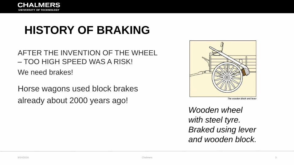
HISTORY OF BRAKING
Horse wagons used block brakes
already about 2000 years ago!
AFTER THE INVENTION OF THE WHEEL
– TOO HIGH SPEED WAS A RISK!
We need brakes!
Wooden wheel
with steel tyre.
Braked using lever
and wooden block.
9/14/2016 Chalmers 4
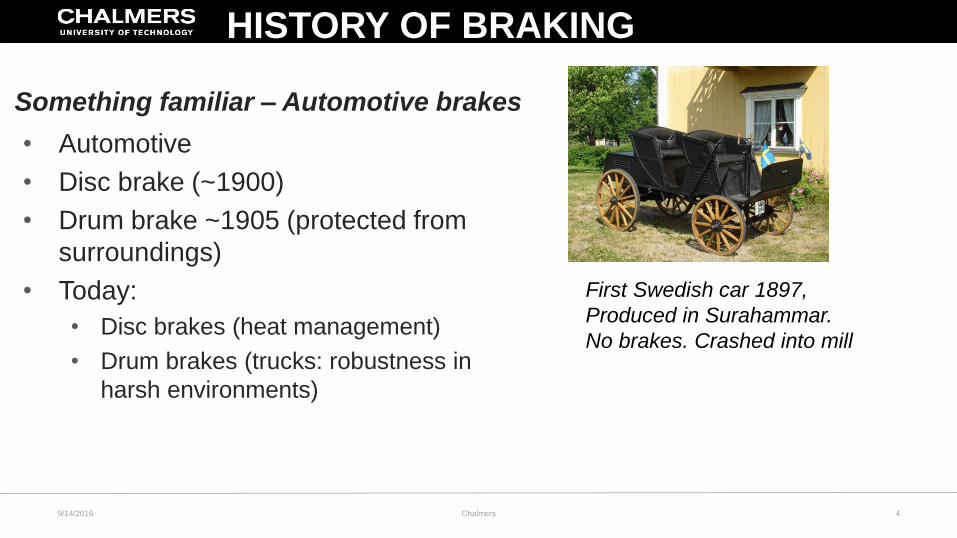
• Automotive
• Disc brake (~1900)
• Drum brake ~1905 (protected from
surroundings)
• Today:
• Disc brakes (heat management)
• Drum brakes (trucks: robustness in
harsh environments)
Something familiar – Automotive brakes
First Swedish car 1897,
Produced in Surahammar.
No brakes. Crashed into mill
HISTORY OF BRAKING
9/14/2016 Chalmers 5
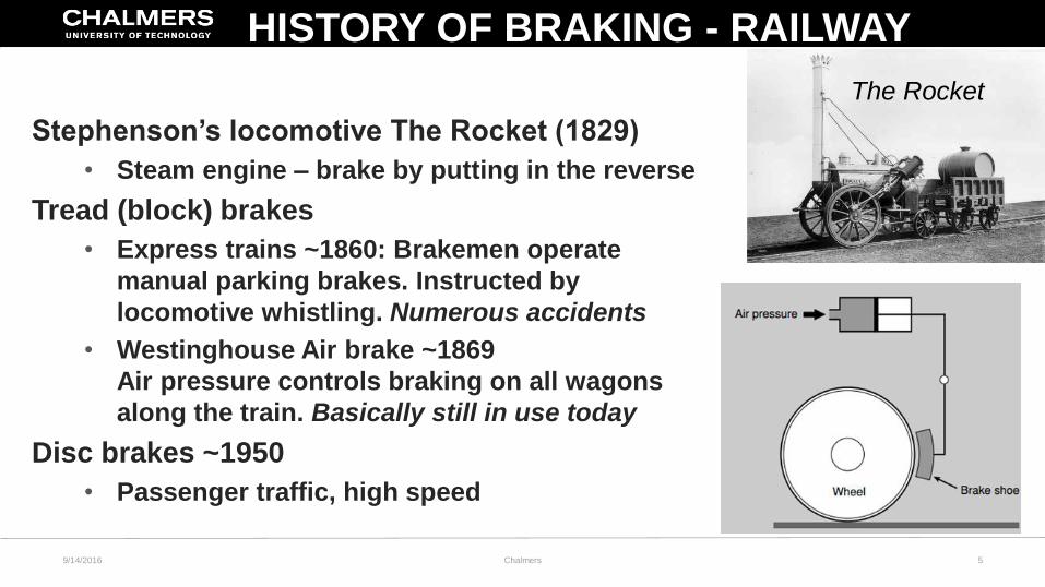
Stephenson’s locomotive The Rocket (1829)
• Steam engine – brake by putting in the reverse
Tread (block) brakes
• Express trains ~1860: Brakemen operate
manual parking brakes. Instructed by
locomotive whistling. Numerous accidents
• Westinghouse Air brake ~1869
Air pressure controls braking on all wagons
along the train. Basically still in use today
Disc brakes ~1950
• Passenger traffic, high speed
The Rocket
HISTORY OF BRAKING - RAILWAY
9/14/2016 Chalmers 6
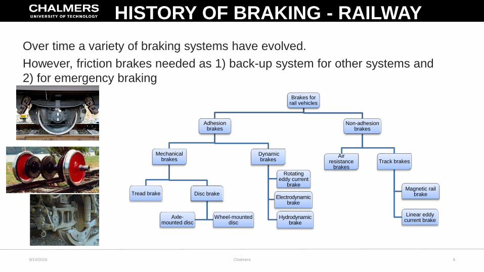
Over time a variety of braking systems have evolved.
However, friction brakes needed as 1) back-up system for other systems and
2) for emergency braking
Brakes for rail vehicles
Adhesion brakes
Mechanical brakes
Tread brake Disc brake
Axle-mounted disc
Wheel-mounted disc
Dynamic brakes
Hydrodynamicbrake
Electrodynamicbrake
Rotatingeddy current
brake
Non-adhesion brakes
Track brakes
Magnetic rail brake
Linear eddy current brake
Air resistance
brakes
HISTORY OF BRAKING - RAILWAY
9/14/2016 Chalmers 7
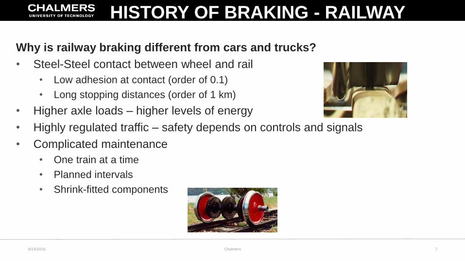
Why is railway braking different from cars and trucks?
• Steel-Steel contact between wheel and rail
• Low adhesion at contact (order of 0.1)
• Long stopping distances (order of 1 km)
• Higher axle loads – higher levels of energy
• Highly regulated traffic – safety depends on controls and signals
• Complicated maintenance
• One train at a time
• Planned intervals
• Shrink-fitted components
HISTORY OF BRAKING - RAILWAY
9/14/2016 Chalmers 8
GENERAL ON FRICTION BRAKES
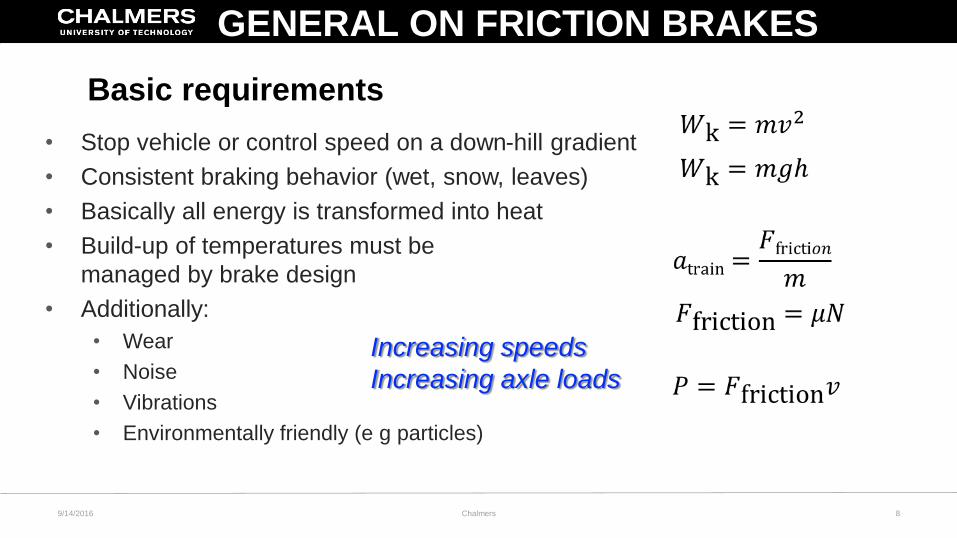
• Stop vehicle or control speed on a down-hill gradient
• Consistent braking behavior (wet, snow, leaves)
• Basically all energy is transformed into heat
• Build-up of temperatures must be
managed by brake design
• Additionally:
• Wear
• Noise
• Vibrations
• Environmentally friendly (e g particles)
Increasing speeds
Increasing axle loads
Basic requirements
9/14/2016 Chalmers 9
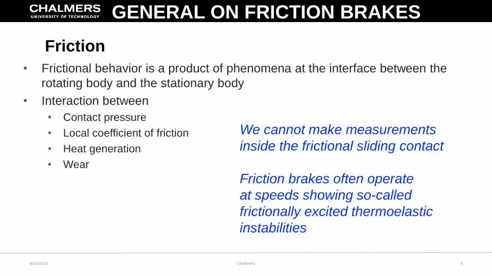
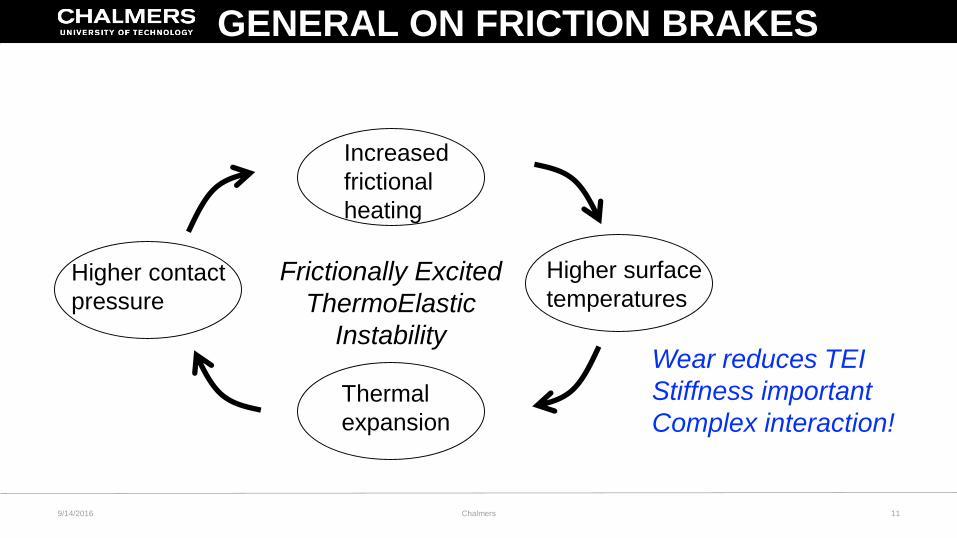
• Frictional behavior is a product of phenomena at the interface between the
rotating body and the stationary body
• Interaction between
• Contact pressure
• Local coefficient of friction
• Heat generation
• Wear
We cannot make measurements
inside the frictional sliding contact
Friction brakes often operate
at speeds showing so-called
frictionally excited thermoelastic
instabilities
GENERAL ON FRICTION BRAKES
Friction
9/14/2016 Chalmers 11
Higher contact
pressure
Increased
frictional
heating
Higher surface
temperatures
Thermal
expansion
Frictionally Excited
ThermoElastic
InstabilityWear reduces TEI
Stiffness important
Complex interaction!
GENERAL ON FRICTION BRAKES
9/14/2016 Chalmers 13
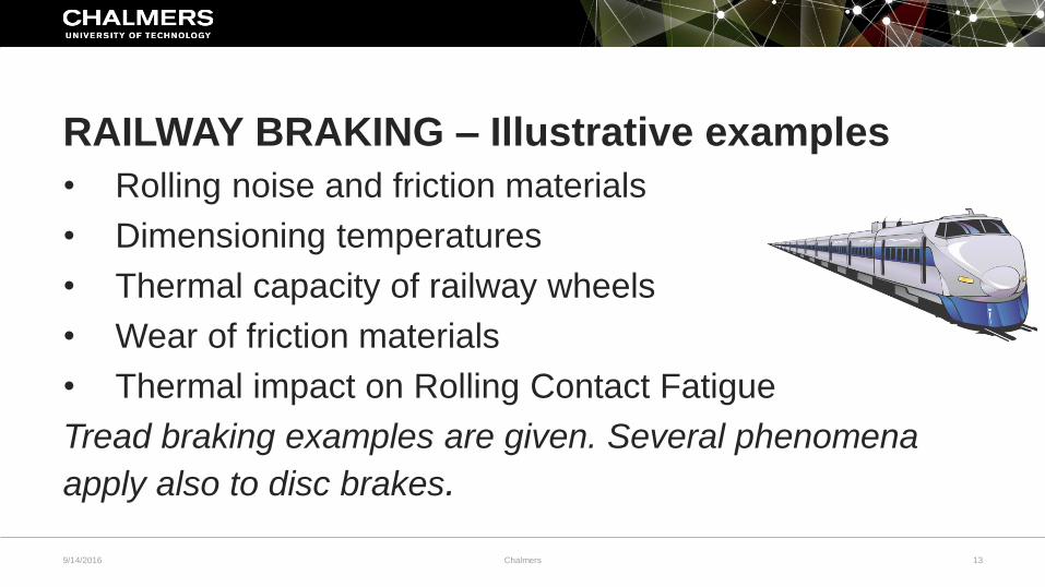
RAILWAY BRAKING – Illustrative examples
• Rolling noise and friction materials
• Dimensioning temperatures
• Thermal capacity of railway wheels
• Wear of friction materials
• Thermal impact on Rolling Contact Fatigue
Tread braking examples are given. Several phenomena
apply also to disc brakes.
14(28)
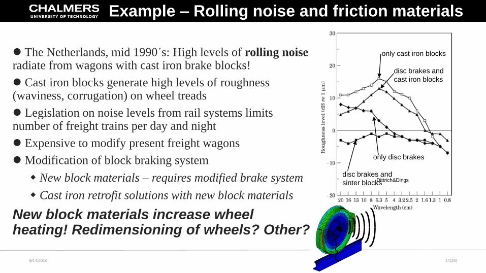
only cast iron blocks
disc brakes and
cast iron blocks
only disc brakes
disc brakes and
sinter blocks
The Netherlands, mid 1990´s: High levels of rolling noise radiate from wagons with cast iron brake blocks!
Cast iron blocks generate high levels of roughness (waviness, corrugation) on wheel treads
Legislation on noise levels from rail systems limits number of freight trains per day and night
Expensive to modify present freight wagons
Modification of block braking system
New block materials – requires modified brake system
Cast iron retrofit solutions with new block materials
New block materials increase wheel heating! Redimensioning of wheels? Other?
Dittrich&Dings
Example – Rolling noise and friction materials
9/14/2016
15(28)
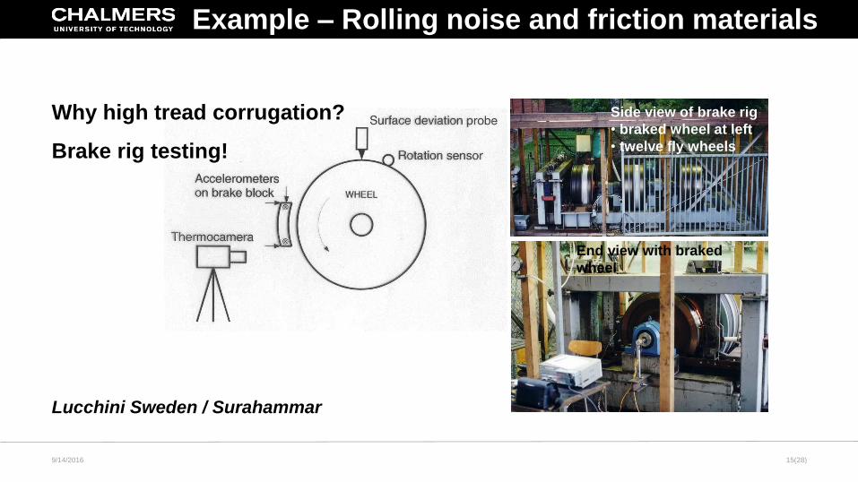
Why high tread corrugation?
Brake rig testing!
Lucchini Sweden / Surahammar
Side view of brake rig
• braked wheel at left
• twelve fly wheels
End view with braked
wheel
Example – Rolling noise and friction materials
9/14/2016
16(28)
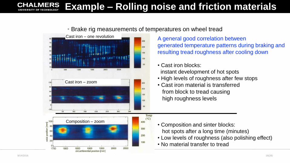
• Brake rig measurements of temperatures on wheel tread
A general good correlation between
generated temperature patterns during braking and
resulting tread roughness after cooling down
• Cast iron blocks:
instant development of hot spots
• High levels of roughness after few stops
• Cast iron material is transferred
from block to tread causing
high roughness levels
• Composition and sinter blocks:
hot spots after a long time (minutes)
• Low levels of roughness (also polishing effect)
• No material transfer to tread
Cast iron – one revolution
Composition – zoom
Cast iron – zoom
Example – Rolling noise and friction materials
9/14/2016
17(28)
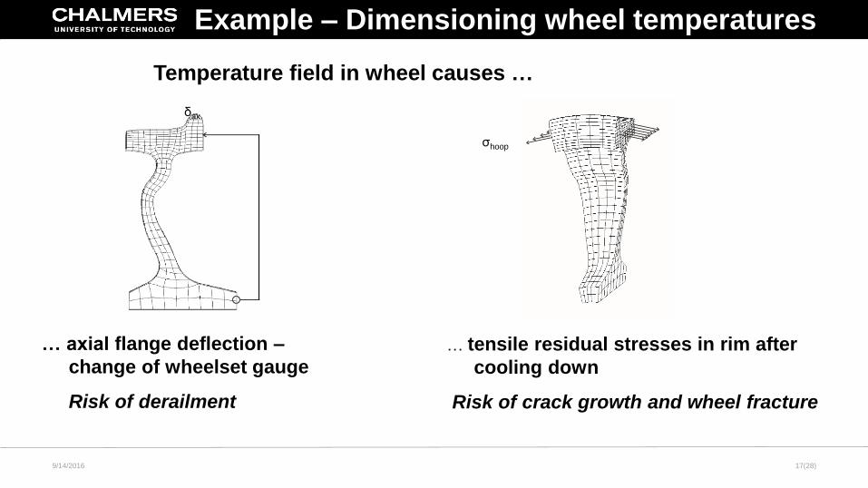
Temperature field in wheel causes …
δax
σhoop
… axial flange deflection –
change of wheelset gauge
Risk of derailment
… tensile residual stresses in rim after
cooling down
Risk of crack growth and wheel fracture
Example – Dimensioning wheel temperatures
9/14/2016
18(28)
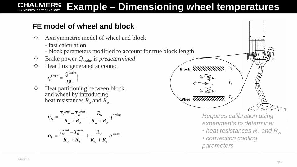
Axisymmetric model of wheel and block
- fast calculation- block parameters modified to account for true block length
Brake power Qbrake is predetermined
Heat flux generated at contact
Heat partitioning between block and wheel by introducingheat resistances Rb and Rw
)
2
1(1
b
brakebrake
tBL
FE model of wheel and block
qbrake
qw
qb R
b
R
w
Tc
Block
WheelTw
Tb
brake
bw
b
bw
contw
contb
w qRR
R
RR
TTq
brake
bw
w
bw
cont
b
cont
w
b qRR
R
RR
TTq
Requires calibration using
experiments to determine:
• heat resistances Rb and Rw
• convection cooling
parameters
Example – Dimensioning wheel temperatures
9/14/2016
19(28)
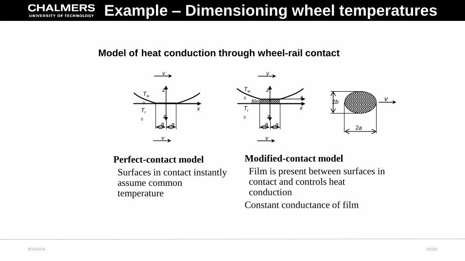
Model of heat conduction through wheel-rail contact
v
v
a
x
z
z
a
filmx
v
v
a
x
z
z
a
Tw
0
Tr
0
Tr
0
Tw
0
Perfect-contact model
Surfaces in contact instantly assume common temperature
Modified-contact model
Film is present between surfaces in contact and controls heat conduction
Constant conductance of film
2a
2bv
Example – Dimensioning wheel temperatures
9/14/2016
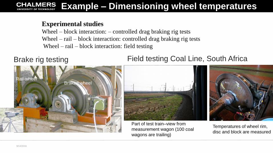
Experimental studiesWheel – block interaction: – controlled drag braking rig tests
Wheel – rail – block interaction: controlled drag braking rig tests
Wheel – rail – block interaction: field testing
Brake rig testing
Braked wheelRail-wheel
Field testing Coal Line, South Africa
Part of test train–view from
measurement wagon (100 coal
wagons are trailing)
Temperatures of wheel rim,
disc and block are measured
Example – Dimensioning wheel temperatures
9/14/2016
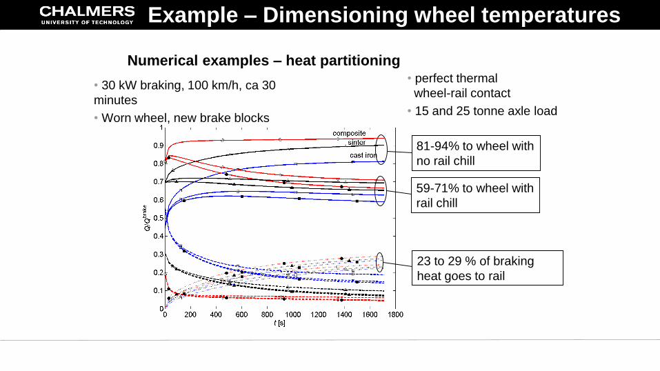
Numerical examples – heat partitioning
• 30 kW braking, 100 km/h, ca 30
minutes
• Worn wheel, new brake blocks
• perfect thermal
wheel-rail contact
• 15 and 25 tonne axle load
81-94% to wheel with
no rail chill
59-71% to wheel with
rail chill
23 to 29 % of braking
heat goes to rail
Example – Dimensioning wheel temperatures
9/14/2016 Chalmers 23
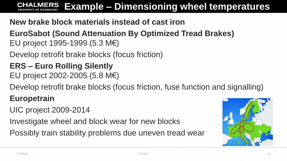
New brake block materials instead of cast iron
EuroSabot (Sound Attenuation By Optimized Tread Brakes)
EU project 1995-1999 (5.3 M€)
Develop retrofit brake blocks (focus friction)
ERS – Euro Rolling Silently
EU project 2002-2005 (5.8 M€)
Develop retrofit brake blocks (focus friction, fuse function and signalling)
Europetrain
UIC project 2009-2014
Investigate wheel and block wear for new blocks
Possibly train stability problems due uneven tread wear
Example – Dimensioning wheel temperatures
9/14/2016 Chalmers 24
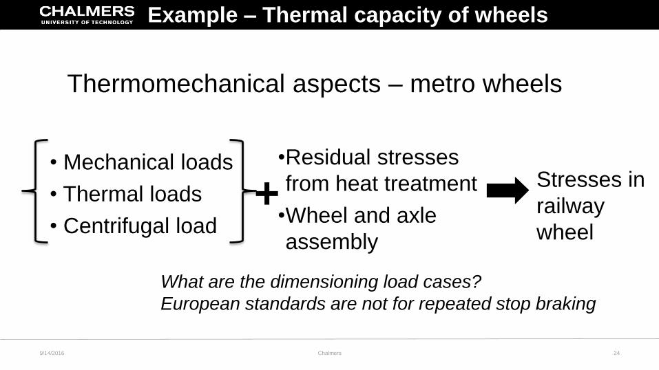
Thermomechanical aspects – metro wheels
• Mechanical loads
• Thermal loads
• Centrifugal load+
•Residual stresses
from heat treatment
•Wheel and axle
assembly
Stresses in
railway
wheel
What are the dimensioning load cases?
European standards are not for repeated stop braking
Example – Thermal capacity of wheels
9/14/2016 Chalmers 25
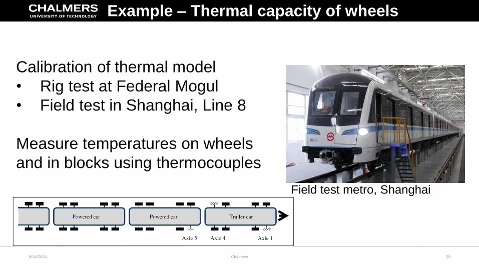
Calibration of thermal model
• Rig test at Federal Mogul
• Field test in Shanghai, Line 8
Measure temperatures on wheels
and in blocks using thermocouples
Field test metro, Shanghai
Example – Thermal capacity of wheels
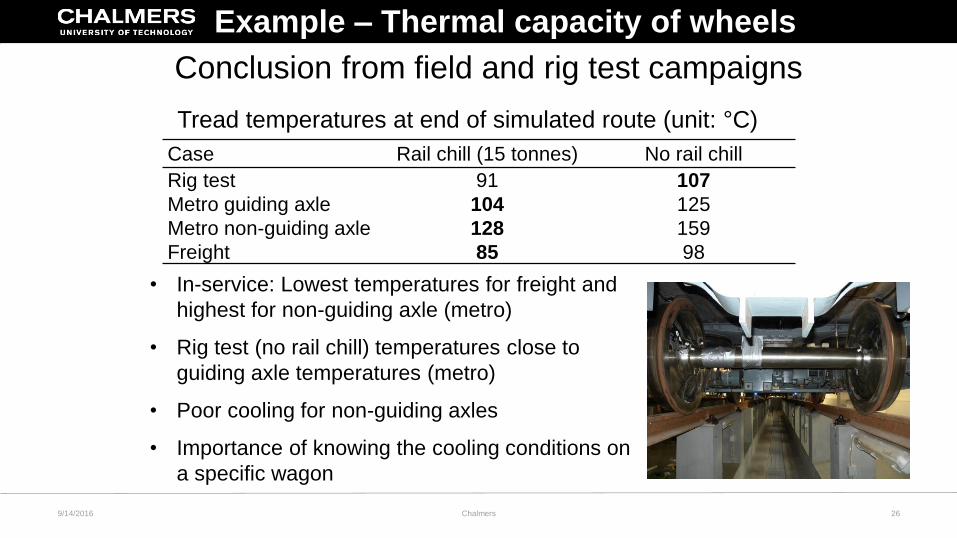
Conclusion from field and rig test campaigns
Case Rail chill (15 tonnes) No rail chill
Rig test 91 107
Metro guiding axle 104 125
Metro non-guiding axle 128 159
Freight 85 98
Tread temperatures at end of simulated route (unit: °C)
• In-service: Lowest temperatures for freight and
highest for non-guiding axle (metro)
• Rig test (no rail chill) temperatures close to
guiding axle temperatures (metro)
• Poor cooling for non-guiding axles
• Importance of knowing the cooling conditions on
a specific wagon
26
Example – Thermal capacity of wheels
9/14/2016 Chalmers
27
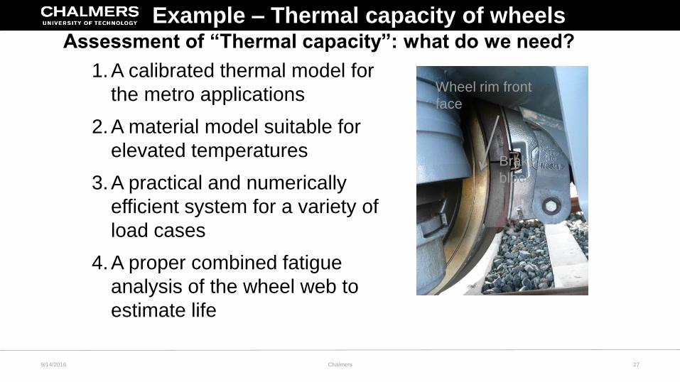
Assessment of “Thermal capacity”: what do we need?
1.A calibrated thermal model for
the metro applications
2.A material model suitable for
elevated temperatures
3.A practical and numerically
efficient system for a variety of
load cases
4.A proper combined fatigue
analysis of the wheel web to
estimate life
Brake
block
Wheel rim front
face
Example – Thermal capacity of wheels
9/14/2016 Chalmers
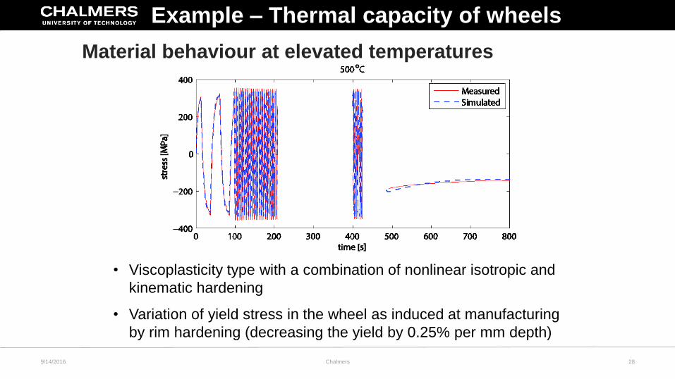
Material behaviour at elevated temperatures
28
• Viscoplasticity type with a combination of nonlinear isotropic and
kinematic hardening
• Variation of yield stress in the wheel as induced at manufacturing
by rim hardening (decreasing the yield by 0.25% per mm depth)
Example – Thermal capacity of wheels
9/14/2016 Chalmers
31
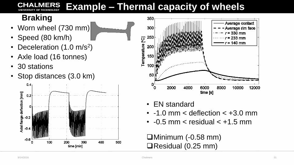
Thermomechanical results
• Worn wheel (730 mm)
• Speed (80 km/h)
• Deceleration (1.0 m/s2)
• Axle load (16 tonnes)
• 30 stations
• Stop distances (3.0 km)
• EN standard
• -1.0 mm < deflection < +3.0 mm
• -0.5 mm < residual < +1.5 mm
Minimum (-0.58 mm)
Residual (0.25 mm)
Example – Thermal capacity of wheelsBraking
9/14/2016 Chalmers
32
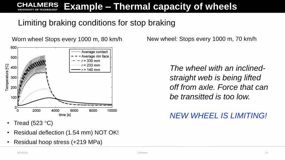
Limiting braking conditions for stop braking
New wheel: Stops every 1000 m, 70 km/hWorn wheel Stops every 1000 m, 80 km/h
• Tread (523 °C)
• Residual deflection (1.54 mm) NOT OK!
• Residual hoop stress (+219 MPa)
Example – Thermal capacity of wheels
The wheel with an inclined-
straight web is being lifted
off from axle. Force that can
be transitted is too low.
NEW WHEEL IS LIMITING!
9/14/2016 Chalmers
34
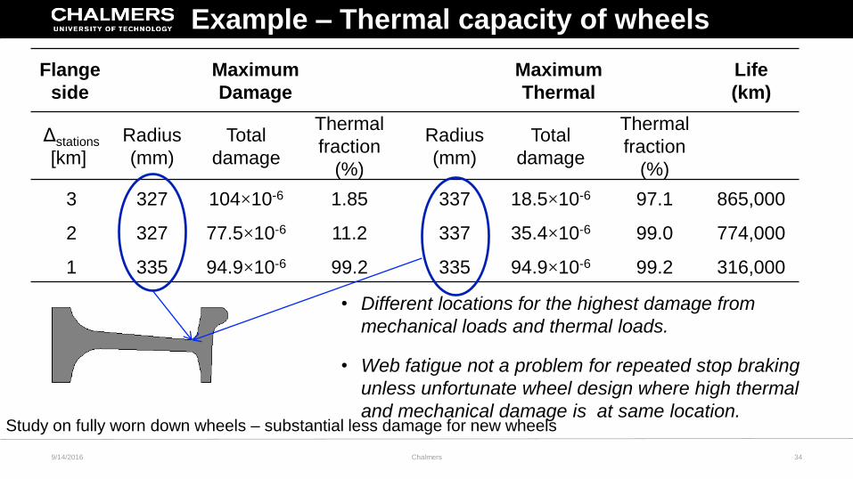
Damage evaluation
Flange
side
Maximum
Damage
Maximum
Thermal
Life
(km)
Δstations
[km]
Radius
(mm)
Total
damage
Thermal
fraction
(%)
Radius
(mm)
Total
damage
Thermal
fraction
(%)
3 327 104×10-6 1.85 337 18.5×10⁻⁶ 97.1 865,000
2 327 77.5×10⁻⁶ 11.2 337 35.4×10⁻⁶ 99.0 774,000
1 335 94.9×10⁻⁶ 99.2 335 94.9×10⁻⁶ 99.2 316,000
• Different locations for the highest damage from
mechanical loads and thermal loads.
• Web fatigue not a problem for repeated stop braking
unless unfortunate wheel design where high thermal
and mechanical damage is at same location.Study on fully worn down wheels – substantial less damage for new wheels
Example – Thermal capacity of wheels
9/14/2016 Chalmers
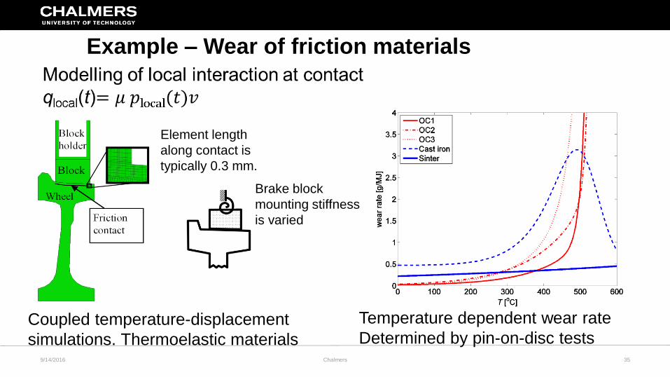
9/14/2016 Chalmers 35
Coupled temperature-displacement
simulations. Thermoelastic materials
Element length
along contact is
typically 0.3 mm.
Brake block
mounting stiffness
is varied
Temperature dependent wear rate
Determined by pin-on-disc tests
Example – Wear of friction materials
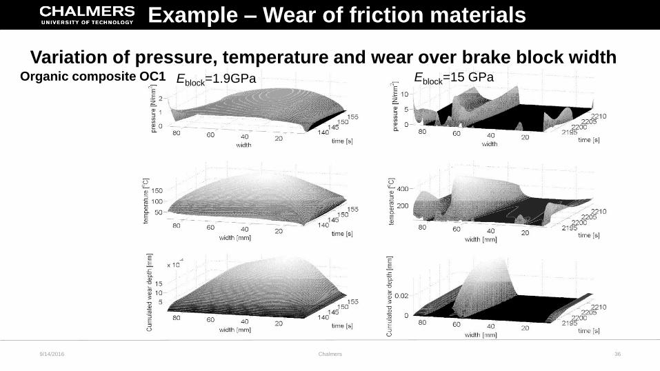
9/14/2016 Chalmers 36
Eblock=1.9GPa Eblock=15 GPaOrganic composite OC1
Example – Wear of friction materials
Variation of pressure, temperature and wear over brake block width
9/14/2016 Chalmers 38
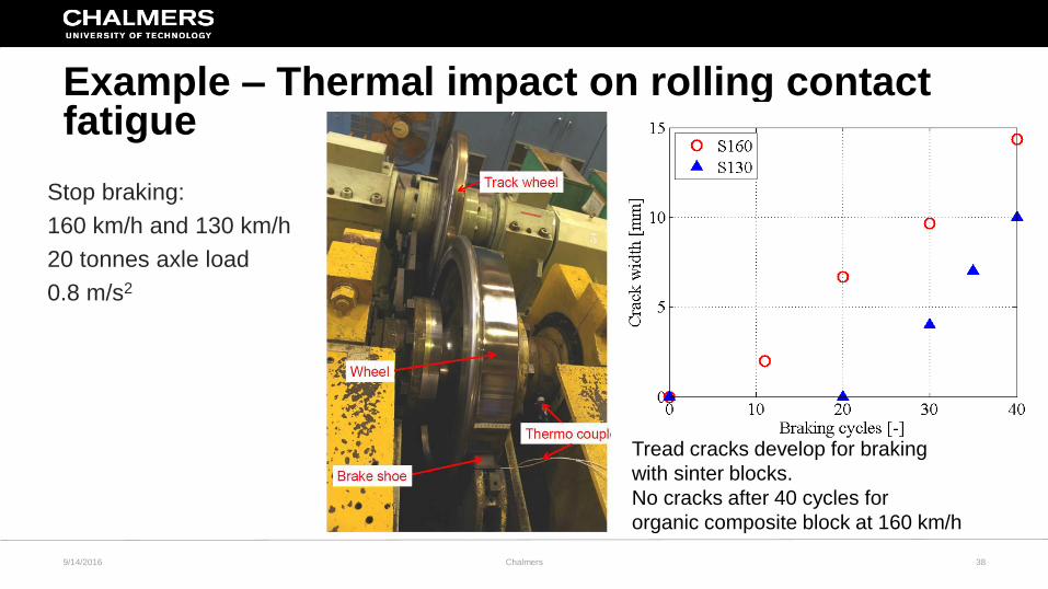
Example – Thermal impact on rolling contact fatigue
Stop braking:
160 km/h and 130 km/h
20 tonnes axle load
0.8 m/s2
Tread cracks develop for braking
with sinter blocks.
No cracks after 40 cycles for
organic composite block at 160 km/h
9/14/2016 Chalmers 39
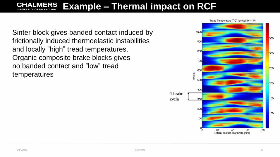
Sinter block gives banded contact induced by
frictionally induced thermoelastic instabilities
and locally ”high” tread temperatures.
Organic composite brake blocks gives
no banded contact and ”low” tread
temperatures
Example – Thermal impact on RCF
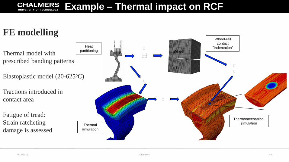
FE modelling
Thermal model with
prescribed banding patterns
Elastoplastic model (20-625oC)
Tractions introduced in
contact area
Fatigue of tread:
Strain ratcheting
damage is assessed
Heat
partitioning
Wheel-rail
contact
”Indentation”
Thermal
simulation
Thermomechanical
simulation
𝑇
𝑇𝑇𝑇𝑇
𝑇
𝑇
𝑇
𝑇
Wheel
Rail
Example – Thermal impact on RCF
9/14/2016 Chalmers 40
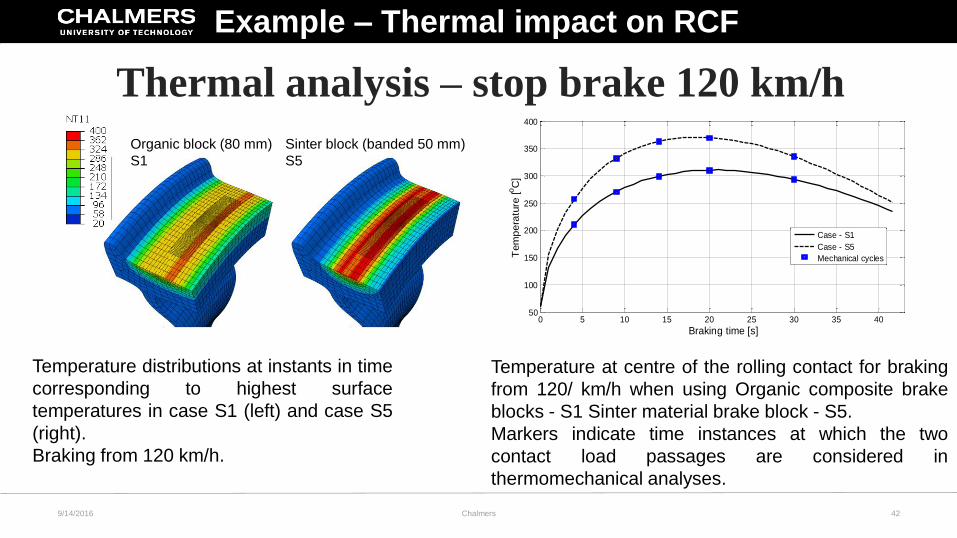
Thermal analysis – stop brake 120 km/h
0 5 10 15 20 25 30 35 4050
100
150
200
250
300
350
400
Braking time [s]
Tem
pe
ratu
re [
oC
]
Case - S1
Case - S5
Mechanical cycles
Temperature distributions at instants in time
corresponding to highest surface
temperatures in case S1 (left) and case S5
(right).
Braking from 120 km/h.
Temperature at centre of the rolling contact for braking
from 120/ km/h when using Organic composite brake
blocks - S1 Sinter material brake block - S5.
Markers indicate time instances at which the two
contact load passages are considered in
thermomechanical analyses.
Organic block (80 mm)
S1
Sinter block (banded 50 mm)
S5
Example – Thermal impact on RCF
9/14/2016 Chalmers 42
9/14/2016 Chalmers 45
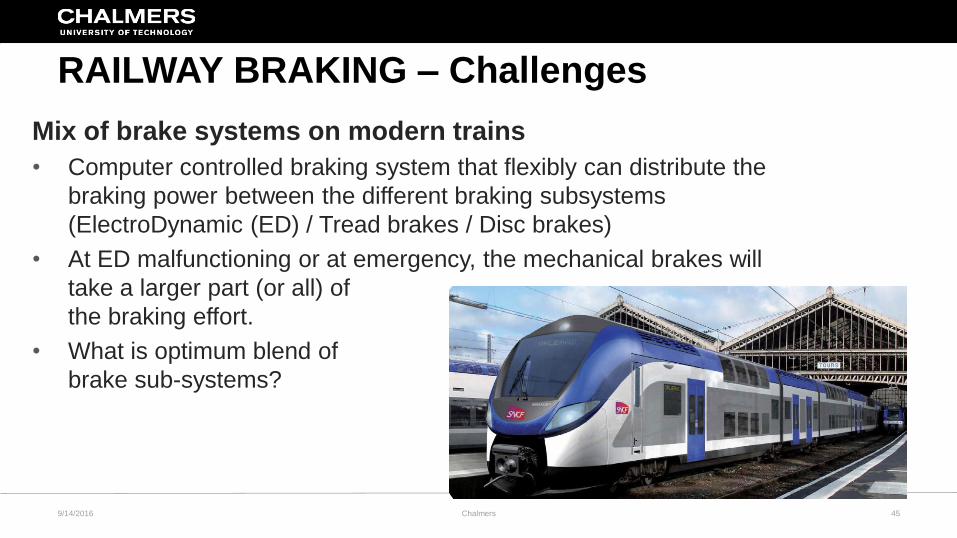
RAILWAY BRAKING – Challenges
Mix of brake systems on modern trains
• Computer controlled braking system that flexibly can distribute the
braking power between the different braking subsystems
(ElectroDynamic (ED) / Tread brakes / Disc brakes)
• At ED malfunctioning or at emergency, the mechanical brakes will
take a larger part (or all) of
the braking effort.
• What is optimum blend of
brake sub-systems?
9/14/2016 Chalmers 46
Assessment of ThermoMechanical Fatigue at high temperatures
Fatigue of wheel, treads, axle mounted brake discs and
wheel-mounted brake discs
• Material model calibration for TMF situation (not isothermally)
• Material models calibrated for multiaxial behavior
• Rate dependent material models
• Unified TMF criterion
RAILWAY BRAKING - CHALLENGES
9/14/2016 Chalmers 48
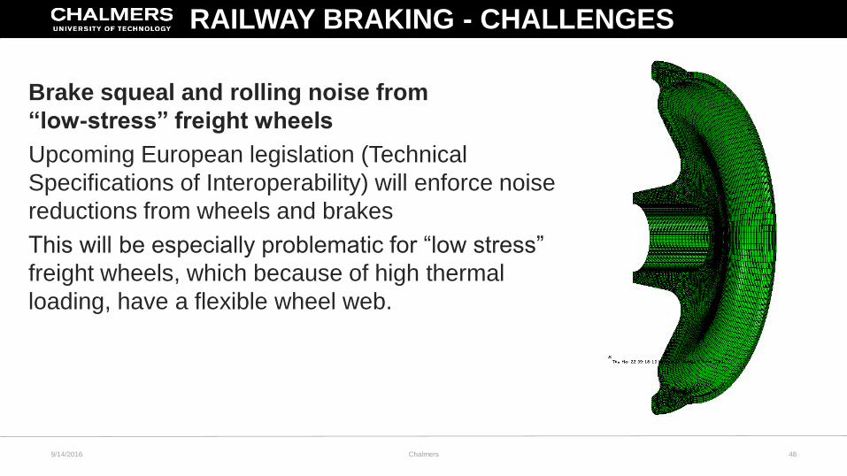
Brake squeal and rolling noise from
“low-stress” freight wheels
Upcoming European legislation (Technical
Specifications of Interoperability) will enforce noise
reductions from wheels and brakes
This will be especially problematic for “low stress”
freight wheels, which because of high thermal
loading, have a flexible wheel web.
RAILWAY BRAKING - CHALLENGES
9/14/2016 Chalmers 49
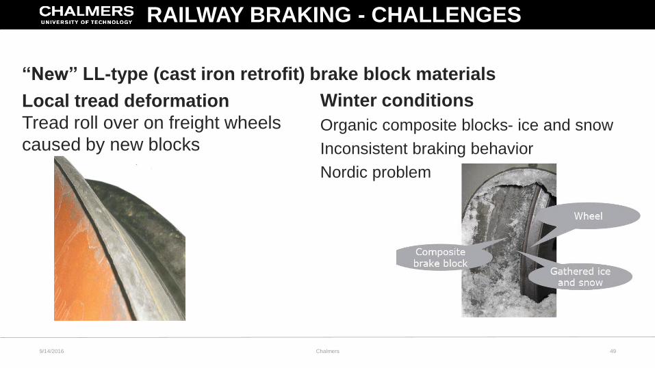
“New” LL-type (cast iron retrofit) brake block materials
Local tread deformation
Tread roll over on freight wheels
caused by new blocks
Winter conditions
Organic composite blocks- ice and snow
Inconsistent braking behavior
Nordic problem
RAILWAY BRAKING - CHALLENGES
9/14/2016 Chalmers 50
RAILWAY FRICTION BRAKING
Concluding remarks
• Interesting and challenging field
• Spans a several areas of research
• Always demands for higher speeds and / or axle loads
• Working in close collaboration with industry
• Enjoyable / Rewarding / Frustrating experimental work
mandatory