Embed Size (px)
Citation preview
a
CHARACTERIZATION OF THE MOLTEN SALT REACTOR EXPERIMENT FUEL AND FLUSH SALTS
David F. Williams Oak Ridge National Laboratory
Lockheed Marietta Energy Research Corp. P. 0. Box 2008
Oak Ridge, Tennessee 3783 1-6224 (423)574-5769
Frederick J. Peretz Central Engineering Services
Lockheed Marietta Energy Systems, Inc. P.O. Box 2008
Oak Ridge, Tennessee 3783 1-6050 (423)576-55 16
Prepared for Presentation at the 1996 American Nuclear Society (ANS)
published by A N S and distributed at the meeting. Meeting in Reno, Nevada, June 16-20, 1996. Proceedings will be
Based on work performed by the Environmental Restoration Program at Oak Ridge National Laboratory,
managed for the U. S . Department of Energy under contract DE-AC05-840R2 1400
with Lockheed Martin Energy Systems, Inc.
“The submitted manuscript has been authored by a contractor of the U.S. Government under contract DE-AC05-840R21400. Accordingly, the U.S. Government retains a nonexclusive, royalty-free license to publish or reproduce the published form of this contribution, or allow others to do so, for U.S. Government purposes”
D I S V
This report was prepared as an account of work sponsored by an agency of the United States Government. Neither the United States Government nor any agency thereof, nor any of their employees, makes any warranty, express or implied, or assumes any legal liability or responsi- bility for the accuracy, completeness, or usefulness of any information, apparatus, product, or process disclosed, or represents that its use would not infringe privately owned rights. Refer- ence herein to any specific commercial product, process, or service by trade name, trademark, manufacturer, or otherwise does not necessarily constitute or imply its endorsement, recom- mendation, or favoring by the United States Government or any agency thereof. The views and opinions of authors expressed herein do not necessarily state or reflect those of the United States Government or any a e n c y thereof.
DfSTRiBUTlON OF THIS ~~~~
DISCLAIMER
Portions of this document may be illegible in electronic image products. Images are produced from the best available original document.
CHARACTERIZATION OF THE MOLTEN SALT REACTOR EXPERIMENT FUEL AND FLUSH SALTS
David F. Williams Oak Ridge National Laboratory Lockheed Marietta Energy Research Corp. P.O. Box 2008 Oak Ridge, Tennessee 3783 1-6224 (423) 574-5769
ABSTRACT
Wise decisions about the handling and disposition of spent fuel from the Molten Salt Reactor Experiment (MSRE) must be based upon an understanding of the physical, chemical, and radiological properties of the frozen fuel and flush salts. These “static” properties can be inferred from the extensive documentation of process history maintained during reactor operation and the knowledge gained in laboratory development studies. Just as important as the description of the salt itself is an understanding of the dynamic processes which continue to transform the salt composition and govern its present and potential physicochemical behavior. A complete characterization must include a phenomenological characterization in addition to the typical summary of properties. This paper reports on the current state of characterization of the fuel and flush salts needed to support waste management decisions.
I. INTRODUCTION
The MSRE was a unique and highly successful scientific venture, and some background is required to put the disposition of its spent fuel in proper perspective. The section on the history of the MSRE fulfills the need to explain how we arrived at the present condition, and provides the basic scope and nature of the MSRE facility. Our present interest in the MSRE is driven by the need to devise a safe and effective plan for disposition of the fuel and flush salts. This motivation and the related salt disposition options are explored in section 111. The balance of the paper is devoted to description of the important characteristics of the MSRE fuel and flush salts, with special emphasis on those dynamic processes which may influence our choice of remediation path.
Frederick J. Peretz Central Engineering Services Lockheed Martin Energy Systems, Inc. P.O. Box 2008 Oak Ridge, Tennessee 3783 1-6050 (423) 576-5516
11. HISTORY OF THE MSRE
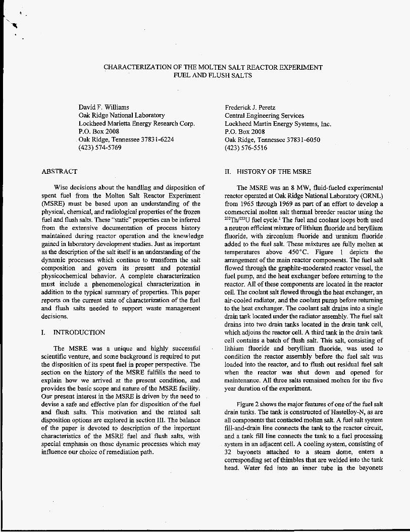
The MSRE was an 8 MW, fluid-fueled experimental reactor operated at Oak Ridge National Laboratory (ORNL) from 1965 through 1969 as part of an effort to develop a commercial molten salt thermal breeder reactor using the 232ThP33U fuel cycle.’ The fuel and coolant loops both used a neutron efficient mixture of lithium fluoride and beryllium fluoride, with zirconium fluoride and uranium fluoride added to the fuel salt. These mixtures are fully molten at temperatures above 450°C. Figure 1 depicts the arrangement of the main reactor components. The fuel salt flowed through the graphite-moderated reactor vessel, the fuel pump, and the heat exchanger before returning to the reactor. All of these components are located in the reactor cell. The coolant salt flowed through the heat exchanger, an air-cooled radiator, and the coolant pump before returning to the heat exchanger. The coolant salt drains into a single drain tank located under the radiator assembly. The fuel salt drains into two drain tanks located in the drain tank cell, which adjoins the reactor cell. A third tank in the drain tank cell contains a batch of flush salt. This salt, consisting of lithium fluoride and beryllium fluoride, was used to condition the reactor assembly before the fuel salt was loaded into the reactor, and to flush out residual fuel salt when the reactor was shut down and opened for maintenance. All three salts remained molten for the five year duration of the experiment.
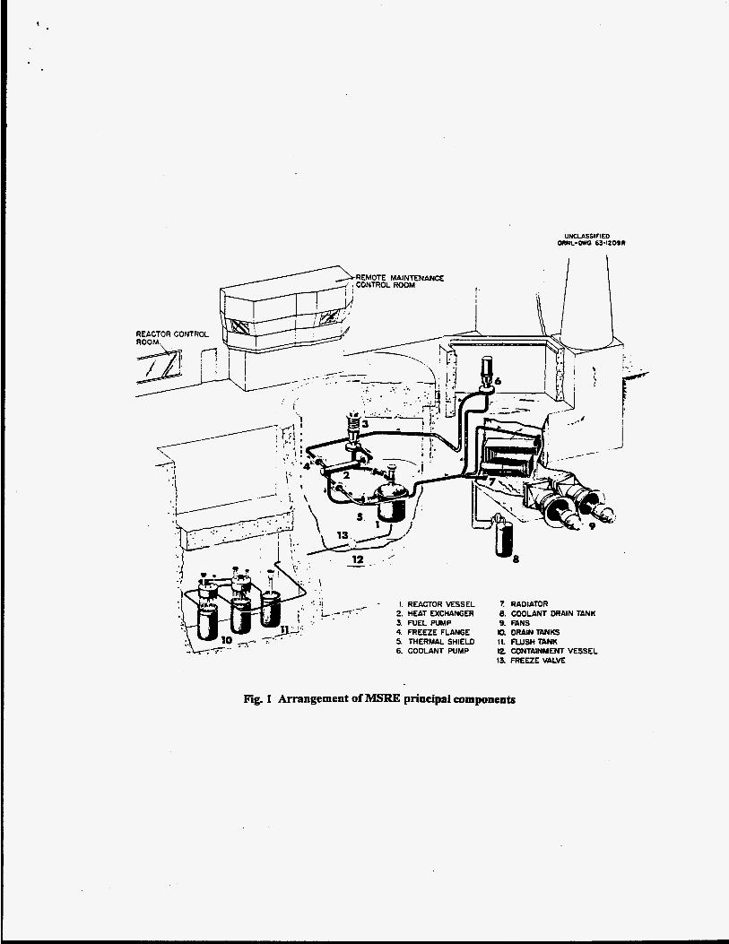
Figure 2 shows the major features of one of the fuel salt drain tanks. The tank is constructed of Hastelloy-N, as are all components that contacted molten salt. A fuel salt system fill-and-drain line connects the tank to the reactor circuit, and a tank fill line connects the tank to a fuel processing system in an adjacent cell. A cooling system, consisting of 32 bayonets attached to a steam dome, enters a corresponding set of thimbles that are welded into the tank head. Water fed into an inner tube in the bayonets
UNCLASSIFIEO ORNL-WG 63-l209R
1 RADIATOR 8. COOLANT DRAIN TANK 9. FANS 0. DRAINTANKS 11. RUSH TANK 12 CONTAINMENT VESSEL 13 FREEZE VAlVE
Fig. 1 Arrangement of MSRE principal components
INSPECTION, SAMPLER. AND LEVEL PROBE ACCESS r
TANK FILL LINE FUELSALTSmEM FILL AND DRAIN LINE
Fig. 2 Sketch of an MSRE fuel drain tank
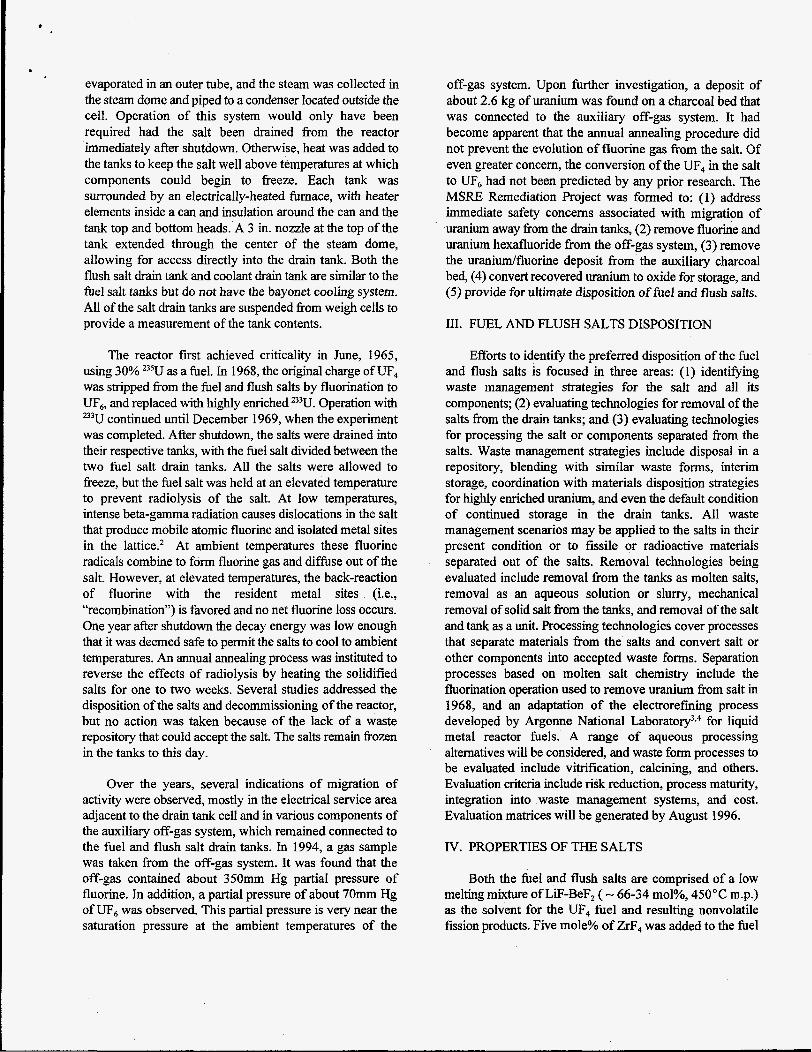
evaporated in an outer tube, and the steam was collected in the steam dome and piped to a condenser located outside the cell. Operation of this system would only have been required had the salt been drained from the reactor immediately after shutdown. Otherwise, heat was added to the tanks to keep the salt well above temperatures at which components could begin to freeze. Each tank was surrounded by an electrically-heated furnace, with heater elements inside a can and insulation around the can and the tank top and bottom heads. A 3 in. nozzle at the top of the tank extended through the center of the steam dome, allowing for access directly into the drain tank. Both the flush salt drain tank and coolant drain tank are similar to the fuel salt tanks but do not have the bayonet cooling system. All of the salt drain tanks are suspended fiom weigh cells to provide a measurement of the tank contents.
The reactor first achieved criticality in June, 1965, using 30% 235U as a fuel. In 1968, the original charge of UF, was stripped fiom the fuel and flush salts by fluorination to UF,, and replaced with highly enriched 233U. Operation with 233U continued until December 1969, when the experiment was completed. After shutdown, the salts were drained into their respective tanks, with the fuel salt divided between the two fuel salt drain tanks. All the salts were allowed to freeze, but the fuel salt was held at an elevated temperature to prevent radiolysis of the salt. At low temperatures, intense beta-gamma radiation causes dislocations in the salt that produce mobile atomic fluorine and isolated metal sites in the lattice? At ambient temperatures these fluorine radicals combine to form fluorine gas and diffuse out of the salt. However, at elevated temperatures, the back-reaction of fluorine with the resident metal sites (Le., “recombination”) is favored and no net fluorine loss occurs. One year after shutdown the decay energy was low enough that it was deemed safe to permit the salts to cool to ambient temperatures. An annual annealing process was instituted to reverse the effects of radiolysis by heating the solidified salts for one to two weeks. Several studies addressed the disposition of the salts and decommissioning of the reactor, but no action was taken because of the lack of a waste repository that could accept the salt. The salts remain frozen in the tanks to this day.
Over the years, several indications of migration of activity were observed, mostly in the electrical service area adjacent to the drain tank cell and in various components of the auxiliary off-gas system, which remained connected to the fuel and flush salt drain tanks. In 1994, a gas sample was taken from the off-gas system. It was found that the off-gas contained about 350mm Hg partial pressure of fluorine. In addition, a partial pressure of about 70mm Hg of uF6 was observed. This partial pressure is very near the saturation pressure at the ambient temperatures of the
off-gas system. Upon further investigation, a deposit of about 2.6 kg of uranium was found on a charcoal bed that was connected to the auxiliary off-gas system. It had become apparent that the annual annealing procedure did not prevent the evolution of fluorine gas from the salt. Of even greater concern, the conversion of the VF, in the salt to u F 6 had not been predicted by any prior research. The MSRE Remediation Project was formed to: (1) address immediate safety concerns associated with migration of uranium away from the drain tanks, (2) remove fluorine and uranium hexafluoride fiom the off-gas system, (3) remove the uranium/fluorine deposit from the auxiliary charcoal bed, (4) convert recovered uranium to oxide for storage, and (5) provide for ultimate disposition of fuel and flush salts.
111. FUEL AND FLUSH SALTS DISPOSITION
Efforts to identify the preferred disposition of the fuel and flush salts is focused in three areas: (1) identifying waste management strategies for the salt and all its components; (2) evaluating technologies for removal of the salts from the drain tanks; and (3) evaluating technologies for processing the salt or components separated from the salts. Waste management strategies include disposal in a repository, blending with similar waste forms, interim storage, coordination with materials disposition strategies for highly enriched uranium, and even the default condition of continued storage in the drain tanks. All waste management scenarios may be applied to the salts in their present condition or to fissile or radioactive materials separated out of the salts. Removal technologies being evaluated include removal fkom the tanks as molten salts, removal as an aqueous solution or slurry, mechanical removal of solid salt from the tanks, and removal of the salt and tank as a unit. Processing technologies cover processes that separate materials from the salts and convert salt or other components into accepted waste forms. Separation processes based on molten salt chemistry include the fluorination operation used to remove uranium from salt in 1968, and an adaptation of the electrorefining process developed by Argonne National Lab~ra tory~.~ for liquid metal reactor fuels. A range of aqueous processing alternatives will be considered, and waste form processes to be evaluated include vitrification, calcining, and others. Evaluation criteria include risk reduction, process maturity, integration into waste management systems, and cost. Evaluation matrices will be generated by August 1996.
IV. PROPERTIES OF THE SALTS
Both the fuel and flush salts are comprised of a low melting mixture of LiF-BeF, ( - 66-34 mol%, 450°C m.p.) as the solvent for the UF, fuel and resulting nonvolatile fission products. Five mole% of ZrF, was added to the fuel
.
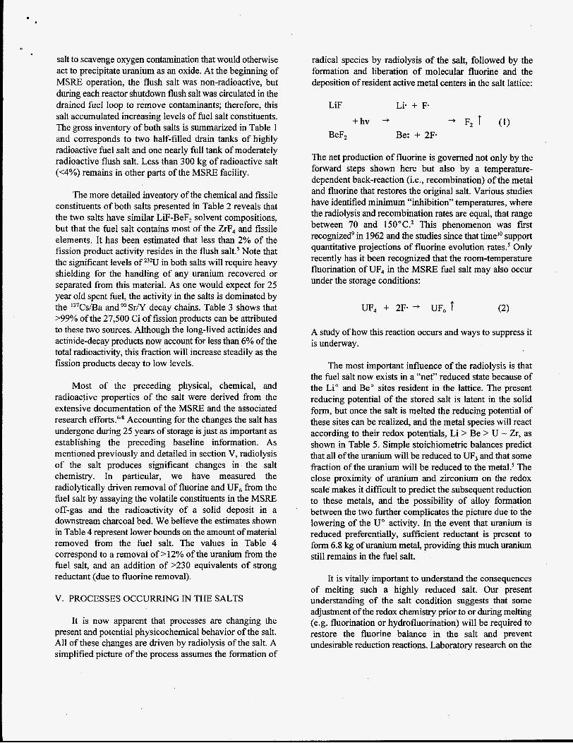
salt to scavenge oxygen contamination that would otherwise act to precipitate uranium as an oxide. At the beginning of MSRE operation, the flush salt was non-radioactive, but during each reactor shutdown flush salt was circulated in the drained fuel loop to remove contaminants; therefore, this salt accumulated increasing levels of fuel salt constituents. The gross inventory of both salts is summarized in Table 1 and corresponds to two half-filled drain tanks of highly radioactive fuel salt and one nearly full tank of moderately radioactive flush salt. Less than 300 kg of radioactive salt (<4%) remains in other parts of the MSRE facility.
The more detailed inventory of the chemical and fissile constituents of both salts presented in Table 2 reveals that the two salts have similar LiF-BeF, solvent compositions, but that the fuel salt contains most of the ZrF, and fissile elements. It has been estimated that less than 2% of the fission product activity resides in the flush salts Note that the significant levels of uzU in both salts will require heavy shielding for the handling of any uranium recovered or separated from this material. As one would expect for 25 year old spent fuel, the activity in the salts is dominated by the 137Cs/Ba and Sr/Y decay chains. Table 3 shows that >99% of the 27,500 Ci of fission products can be attributed to these two sources. Although the long-lived actinides and actinide-decay products now account for less than 6% of the total radioactivity, this fraction will increase steadily as the fission products decay to low levels.
Most of the preceding physical, chemical, and radioactive properties of the salt were derived from the extensive documentation of the MSRE and the associated research efforts.”* Accounting for the changes the salt has undergone during 25 years of storage is just as important as establishing the preceding baseline information. As mentioned previously and detailed in section V, radiolysis of the salt produces significant changes in the salt chemistry. In particular, we have measured the radiolytically driven removal of fluorine and UF, from the fuel salt by assaying the volatile constituents in the MSRE off-gas and the radioactivity of a solid deposit in a downstream charcoal bed. We believe the estimates shown in Table 4 represent lower bounds on the amount of material removed from the fuel salt. The values in Table 4 correspond to a removal of > 12% of the uranium from the fuel salt, and an addition of >230 equivalents of strong reductant (due to fluorine removal).
V. PROCESSES OCCURRING IN THE SALTS
It is now apparent that processes are changing the present and potential physicochemical behavior of the salt. All of these changes are driven by radiolysis of the salt. A simplified picture of the process assumes the formation of
radical species by radiolysis of the salt, followed by the formation and liberation of molecular fluorine and the deposition of resident active metal centers in the salt lattice:
LiF Lie + F.
+hv + + F2 1 (1) BeF, Be: + 2F-
The net production of fluorine is governed not only by the forward steps shown here but also by a temperature- dependent back-reaction (i.e., recombination) of the metal and fluorine that restores the original salt. Various studies have identified minimum “inhibition” temperatures, where the radiolysis and recombination rates are equal, that range between 70 and 150”C.2 This phenomenon was first recognizedg in 1962 and the studies since that timelo support quantitative projections of fluorine evolution rates.s Only recently has it been recognized that the room-temperature fluorination of UF, in the MSRE fuel salt may also occur under the storage conditions:
UF, + 2F* + UF, t
A study of how this reaction occurs and ways to suppress it is underway.
The most important influence of the radiolysis is that the fuel salt now exists in a “net” reduced state because of the Li” and Be” sites resident in the lattice. The present reducing potential of the stored salt is latent in the solid form, but once the salt is melted the reducing potential of these sites can be realized, and the metal species will react according to their redox potentials, Li > Be > U - Zr, as shown in Table 5 . Simple stoichiometric balances predict that all of the uranium will be reduced to UF, and that some fraction of the uranium will be reduced to the metal.5 The close proximity of uranium and zirconium on the redox scale makes it difficult to predict the subsequent reduction to these metals, and the possibility of alloy formation between the two further complicates the picture due to the lowering of the U” activity. In the event that uranium is reduced preferentially, sufficient reductant is present to form 6.8 kg of uranium metal, providing this much uranium still remains in the fuel salt.
It is vitally important to understand the consequences of melting such a highly reduced salt. Our present understanding of the salt condition suggests that some adjustment of the redox chemistry prior to or during melting (e.g. fluorination or hydrofluorination) will be required to restore the fluorine balance in the salt and prevent undesirable reduction reactions. Laboratory research on the
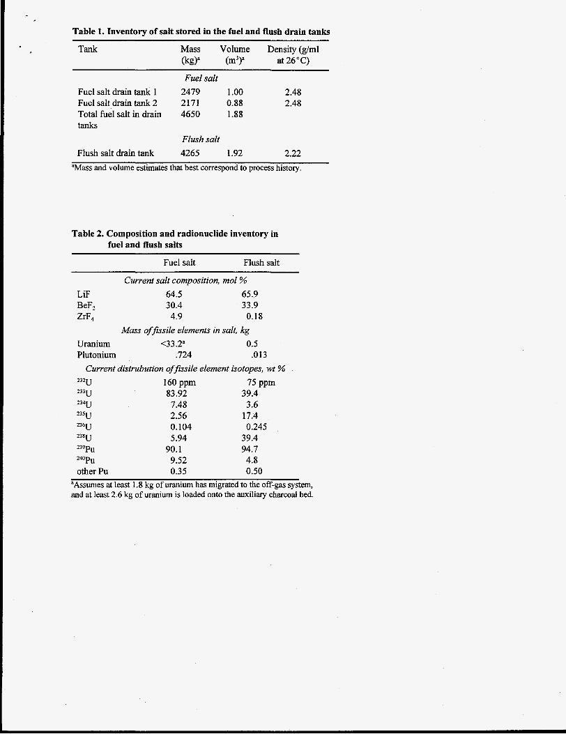
Table 1. Inventory of salt stored in the fuel and flush drain tanks
Tank Mass Volume Density (g/ml (kgY (m3>a at 26°C)
Fuel salt Fuel salt drain tank 1 2479 1 .oo 2.48 Fuel salt drain tank 2 2171 0.88 2.48 Total fuel salt in drain 4650 1.88 tanks
Flush salt Flush salt drain tank 4265 1.92 2.22
“Mass and volume estimates that best correspond to process history.
Table 2. Composition and radionuclide inventory in fuel and flush salts
Fuel salt Flush salt
Current salt composition, mol % LiF 64.5 65.9 BeF, 30.4 33.9 ZrF, 4.9 0.18
Mass ofJisiie elements in salt, kg Uranium <3 3.2“ 0.5 Plutonium .724 .013
Current distrubution ofJissile element isotopes, wt %
160 ppm 75 PPm 232u
233u 83.92 39.4 234u 7.48 3.6 2 3 5 u 2.56 17.4 236u 0.104 0.245 2 3 8 ~ 5.94 39.4 23% 90.1 94.7 240Pu 9.52 4.8 other Pu 0.35 0.50
aAssumes at least 1.8 kg of uranium has migrated to the off-gas system, and at least 2.6 kg of uranium is loaded onto the auxiliary charcoal bed.
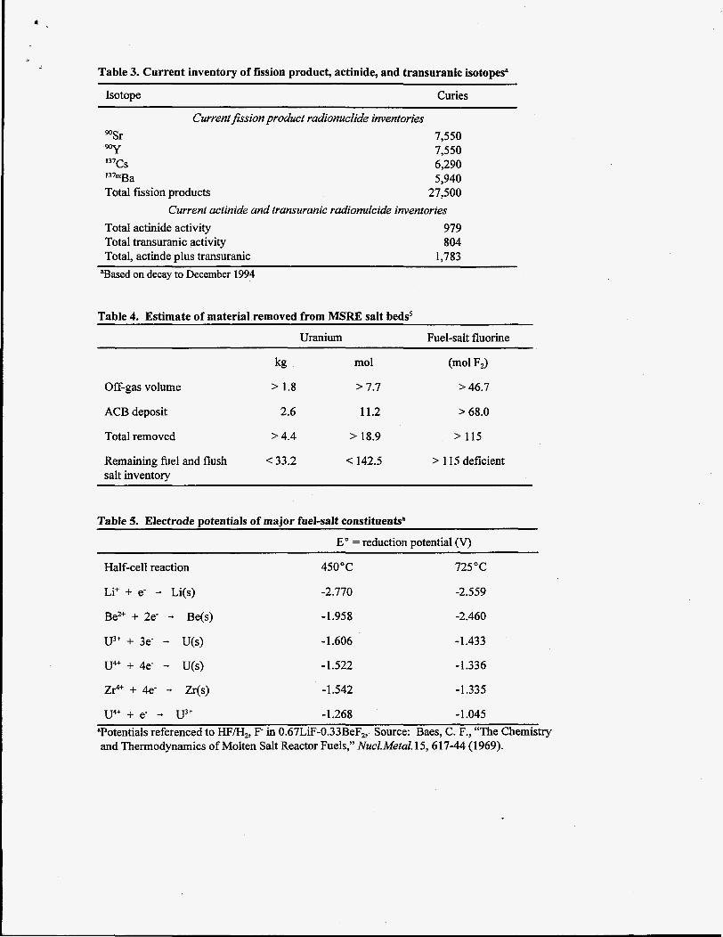
Table 3. Current inventory of fission product, actinide, and transuranic isotopes"
Isotope Curies
Current fission product radionuclide inventories "Sr 90Y I3'Cs
Total fission products I37mga
7,550 7,550 6,290 5,940
27,500 Current actinide and transuranic radionulciak inventories
Total actinide activity 979 Total transuranic activity 804 Total, actinde d u s transuranic 1.783
aBased on decay to December 1994
Table 4. Estimate of material removed from MSRE salt bedsS
Uranium Fuel-salt fluorine
Off-gas volume
ACB deposit 2.6 11.2 > 68.0
Total removed > 4.4 > 18.9 > 115
Remaining fuel and flush 33.2 < 142.5 > 115 deficient salt inventory
Table 5. Electrode potentials of major fuel-salt constituentsa
E" = reduction potential (V)
Half-cell reaction 450°C 725°C
Li' + e- - Li(s) -2.770 -2.559
Be2+ + 2e- - Be(s)
U3+ + 3e- - U(s)
-1.958 -2.460
- 1.606 -1.433
U4+ + 4e- - U(s) -1.522 -1.336
ZIA' + 4e- - Zr(s) -1.542 -1.335
u4+ + e- - U3f -1.268 -1.045 "Potentials referenced to HF/H,, F- in 0.67LiF-0.33BeF2, Source: Baes, C. F., "The Chemistry and Thermodynamics of Molten Salt Reactor Fuels," Nucl.Metul. 15,617-44 (1969).
chemistry of reduced fuel-salt simulant is starting and should help answer questions about how to meit the salt safely and effectively.
VI. SUMMARY
Evaluation of salt disposition alternatives requires a comprehensive understanding of the present condition of the fuel and flush salts. Past storage of the salts has been complicated by the generation and migration of F, and UF,. Because of the migration of fluorine, the salts are left in a net reducing condition. Although reaction rates are not significant at ambient temperatures, a set of reducing reactions will likely take place if the salts are heated to their melting points. In particular, it is expected that the lithium and beryllium metal sites in the salts will lead to the reduction of uranium from UF, to UF,, and eventually to uranium metal. A fm understanding of the present salt chemistry and the phenomena which occur during melting reduced salt is needed to devise a safe method for recovery of the salt as a liquid (i.e. without forming uranium metal). If a safe pathway for melting the salt cannot be established, then “molten” salt removal and processing technologies cannot be used. Likewise, a comprehensive definition of the radionuclides present in the salt is needed for the classification of waste forms. Finally, a f m understanding of the mechanisms and rates for the generation of F, and UF, is needed to evaluate continued storage of the salts either in their drain tanks or in new packages.
ACKNOWLEDGMENTS
This paper is based on work performed by the Environmental Restoration Program at Oak Ridge National Laboratory, managed for the U. S. Department of Energy under contract DE-AC05-840R2 1400 with Lockheed Martin Energy Systems.
REFERENCES
1. W.R. Grimes, “Molten Salt Reactor Chemistry,” Nuclear Applications in Technology, 8, 137 (Feb. 1970).
2. L. M Toth, and L. K. Felker, “Fluorine Generation by Gamma Radiolysis of a Fluoride Salt Mixture,” Radiat. Eff De$ Solids 112,201-10 (1990).
3. J. P. Ackerman, “Chemical Basis for Qrochemical Reprocessing of Nuclear Fuel,” Id. Eng. Chem. Res., 30, 141-45 (1990).
5. D. F. Williams, G. D. Del Cui, and L. M. Toth, A Descriptive M&l of the Molten Salt Remtor Experiment A$er Shutdown:ReviewoJFY1995Progr~, ONRLAM-13142, Oak Ridge National Laboratory, Oak Ridge (Jan, 1996).
6. R. E. Thoma, Chemical Aspects of MSRE Operations, ORNL-4658, Oak Ridge National Laboratory, pp. 58-65, 99-1 12, Oak Ridge (December 1971).
7. E. L. Compere, et al., Fission Product Behavior in the Molten Salt Reactor Experiment, ORNL-4865, Oak Ridge National Laboratory, Oak Ridge (Oct. 1975).
8. M. J. Bell, CaIculatedRadioactivi@ of the MSRE Fuelsalt, ORNL/TM-2970, Oak Ridge National Laboratory, Oak Ridge (May 1970).
9. F. F. Blankenship, et al., in Reactor Chemistry Division Annual Progress Reportfor the PeriodEnding Jan. 31,1963, ORNL-3417, Oak Ridge National Laboratory, 17-30, Oak Ridge (Apr. 1963).
10. P. N. Haubenreich, Fluorine Production andRecombination in Frozen UTR salts @er Reactor @ration, ORNwI1M-3 144, Oak Ridge National Laboratory, Oak Ridge (Sep. 1970).
4. R. D. Pierce, et al., “Progress in the Pyrochemical Processing of Spent Nuclear Fuels,” JO M, 45, no. 2,40-44, (Feb. 1993).