Embed Size (px)
Citation preview
Characterization of the Exradin W1 scintillator for use in radiotherapyP. Carrasco, N. Jornet, O. Jordi, M. Lizondo, A. Latorre-Musoll, T. Eudaldo, A. Ruiz, and M. Ribas Citation: Medical Physics 42, 297 (2015); doi: 10.1118/1.4903757 View online: http://dx.doi.org/10.1118/1.4903757 View Table of Contents: http://scitation.aip.org/content/aapm/journal/medphys/42/1?ver=pdfcov Published by the American Association of Physicists in Medicine Articles you may be interested in Accurate calibration of a polymer gel dosimeter with a plastic scintillation detector Med. Phys. 38, 2754 (2011); 10.1118/1.3578601 Evaluation of Al 2 O 3 : C optically stimulated luminescence (OSL) dosimeters for passive dosimetry of high-energy photon and electron beams in radiotherapy Med. Phys. 35, 260 (2008); 10.1118/1.2816106 Spectral discrimination of Čerenkov radiation in scintillating dosimeters Med. Phys. 32, 3000 (2005); 10.1118/1.2008487 Calibration of a scintillation dosemeter for beta rays using an extrapolation ionization chamber Med. Phys. 31, 1123 (2004); 10.1118/1.1709490 Noise in polymer gel measurements using MRI Med. Phys. 27, 1814 (2000); 10.1118/1.1287284
Characterization of the Exradin W1 scintillator for use in radiotherapyP. Carrasco,a) N. Jornet, O. Jordi, M. Lizondo, A. Latorre-Musoll, T. Eudaldo, A. Ruiz,and M. RibasServei de Radiofísica i Radioprotecció, Hospital de la Santa Creu i Sant Pau, Sant Antoni Maria Claret 167,Barcelona 08025, Spain
(Received 17 February 2014; revised 6 November 2014; accepted for publication 20 November 2014;published 23 December 2014)
Purpose: To evaluate the main characteristics of the Exradin W1 scintillator as a dosimeter and toestimate measurement uncertainties when used in radiotherapy.Methods: We studied the calibration procedure, energy and modality dependence, short-term repeat-ability, dose-response linearity, angular dependence, temperature dependence, time to reach thermalequilibrium, dose-rate dependence, water-equivalent depth of the effective measurement point, andlong-term stability. An uncertainty budget was derived for relative and absolute dose measurementsin photon and electron beams.Results: Exradin W1 showed a temperature dependence of −0.225% ◦C−1. The loss of sensitivitywith accumulated dose decreased with use. The sensitivity of Exradin W1 was energy independentfor high-energy photon and electron beams. All remaining dependencies of Exradin W1 were aroundor below 0.5%, leading to an uncertainty budget of about 1%. When a dual channel electrometer withautomatic trigger was not used, timing effects became significant, increasing uncertainties by oneorder of magnitude.Conclusions: The Exradin W1 response is energy independent for high energy x-rays and electronbeams, and only one calibration coefficient is needed. A temperature correction factor should beapplied to keep uncertainties around 2% for absolute dose measurements and around 1% for relativemeasurements in high-energy photon and electron beams. The Exradin W1 scintillator is an excellentalternative to detectors such as diodes for relative dose measurements. C 2015 American Associationof Physicists in Medicine. [http://dx.doi.org/10.1118/1.4903757]
Key words: scintillator dosimeter, radiation therapy measurements, dosimeter characterization
1. INTRODUCTION
The use of scintillation light is one of the oldest techniques onrecord to detect ionizing radiation,1 but it was not until 2013that a dosimeter based on a scintillator became commerciallyavailable. Scintillator materials may be organic or inorganic.Organic plastic scintillators are better than inorganic scintilla-tors for radiotherapy purposes because they are almost water-equivalent and they can be manufactured in small dimensions.The reason why these plastic scintillators were not used fordosimetry purposes in radiotherapy until recently was thatwithin the light fiber that guides the scintillation light to aphotodiode or a photomultiplier, some Cerenkov light is alsoproduced in the irradiated fiber. The amount of Cerenkovlight depends on the length of the irradiated fiber, thus lead-ing to a variable component that is not easy to quantify andeliminate.
One of the most widely used techniques to eliminate theCerenkov light component is the spectral method.2,3 Thismethod takes advantage of the fact that the scintillation lightspectrum differs from that of Cerenkov light. The former hasa maximum at a wavelength of 500–550 nm (green light) formany plastic scintillators while the latter decreases with thewavelength, and is mainly bluish. To reduce the Cerenkovlight component from the scintillation light, some prototypesin the literature divide the light beam in two by means of two
45◦ reflective dichroic color filters (green and blue) placed atthe end of the light fiber. The green filter selects the greenlight, where most of the scintillation light spectrum is located,and attenuates the blue light, which is mainly produced bythe Cerenkov effect. The blue filter attenuates the scintillationlight and allows the Cerenkov light pass through. Two photodi-odes then convert these light beams into electrical currents thatare integrated by a two-channel electrometer. Guillot et al.3
proposed a calibration method, based on the spectral method,that reduces the Cerenkov effect. The residual uncertainty ofthis calibration method is less than 0.7% for field sizes rangingfrom 7×7 cm2 to 40×40 cm2, an acceptable uncertainty formost dosimetry purposes in external beam radiotherapy.
Recently, a commercial plastic scintillator dosimeter be-came available. This commercial solution uses the spectraldiscrimination method to eliminate the Cerenkov light contam-ination and recommends the calibration method as proposedby Guillot et al.3
Although much has been published on the development andcharacterization of prototypes of PSDs over the last decade,4–8
there is as yet no independent publication from a customershowing the characteristics of the aforementioned commer-cial solution for radiotherapy purposes. This paper aims toevaluate the main characteristics of Exradin W1 scintillator asa dosimeter and to estimate measurement uncertainties whenused in radiotherapy.
297 Med. Phys. 42 (1), January 2015 0094-2405/2015/42(1)/297/8/$30.00 © 2015 Am. Assoc. Phys. Med. 297
298 Carrasco et al.: Characterization of Exradin W1 for radiotherapy 298
2. MATERIALS AND METHODS
We tested an Exradin W1 Scintillator connected to a two-channel SuperMAX electrometer, both devices from StandardImaging Inc., Middleton, WI. The scintillating fiber is basedon polystyrene.
This fiber is surrounded by an acrylonitrile butadiene sty-rene (ABS) plastic enclosure and a polymide stem. The sensi-tive volume of the Exradin W1 scintillator is approximately1 mm diameter by 3 mm long (0.0024 cm3), and the opticaloutput is guided to a photodiode by a clear optical fiber. Theelectrometer was set in triggered charge collection mode forchannel 1 (green light, mainly scintillation light). We used theautomatic start and stop trigger thresholds preconfigured asa default in the Supermax electrometer (start = 0.4 pA andstop = 0.2 pA). Channel 2 collected the signal from blue lightmainly produced by Cerenkov radiation. The electrometersoftware allows automatic correction of the Cerenkov effect.For this work, however, we recorded raw charges for bothchannels and we manually applied the correction to check howit was implemented. We investigated the calibration procedureand the dosimetric characteristics of Exradin W1 for energiesand modalities used for external beam radiotherapy. Thesecharacteristics were energy and modality dependence, short-term repeatability, dose–response linearity, angular depen-dence, temperature dependence, time to reach thermal equi-librium, dose-rate dependence, the water-equivalent depth ofthe effective measurement point, and long-term stability.
We derived A-type uncertainties from the standard devi-ation of series of measurements. Each measurement wasrepeated at least three times. As most tests were relative toa reference value, many uncertainties such as those presentin absolute dose calibration cancelled out. To account for B-type uncertainties, we assumed a uniform probability densityfunction and the associated standard deviation was the inter-val amplitude divided by (12)1/2 according to internationalrecommendations.9 We always included two sources of B-type uncertainties: first, all electrometer uncertainties statedin its calibration certificate and, second, the beam/measuringsystem stability. The latter was estimated from dose measure-ments in reference conditions before and after performingthe test. In specific tests such as the study of temperature
dependence, we accounted for additional B-type uncertainties,like the uncertainty in the temperature measurement. In thisspecific case, we performed two temperature measurements,one before and one after irradiating the scintillator. Addition-ally, we included the temperature uncertainty measurementfrom the thermometer calibration certificate. Standard uncer-tainty propagation was applied.
2.A. Calibration
We calibrated the Exradin W1 against a traceable iono-metric dosimetry system for a 6 MV x-ray beam (Clinac2100C/D, Varian Medical Systems, Palo Alto, CA). We per-formed dose measurements in reference conditions [field size10 × 10 cm2, source–surface distance (SSD) = 100 cm, z= 10 cm] following the IAEA TRS-398 Code of Practice10
using a NE2571 ionization chamber (Thermo Electron Co.,Waltham, MA) and an Inovision 35040 electrometer (FlukeBiomedical, Cleveland, OH) traceable to a secondary labora-tory.
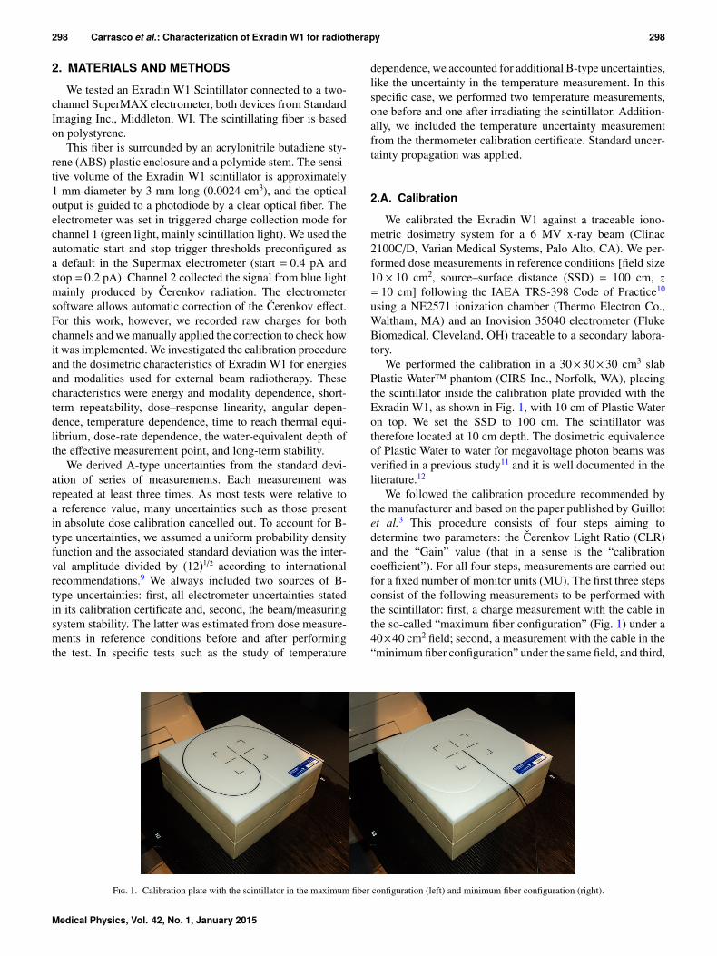
We performed the calibration in a 30×30×30 cm3 slabPlastic Water™ phantom (CIRS Inc., Norfolk, WA), placingthe scintillator inside the calibration plate provided with theExradin W1, as shown in Fig. 1, with 10 cm of Plastic Wateron top. We set the SSD to 100 cm. The scintillator wastherefore located at 10 cm depth. The dosimetric equivalenceof Plastic Water to water for megavoltage photon beams wasverified in a previous study11 and it is well documented in theliterature.12
We followed the calibration procedure recommended bythe manufacturer and based on the paper published by Guillotet al.3 This procedure consists of four steps aiming todetermine two parameters: the Cerenkov Light Ratio (CLR)and the “Gain” value (that in a sense is the “calibrationcoefficient”). For all four steps, measurements are carried outfor a fixed number of monitor units (MU). The first three stepsconsist of the following measurements to be performed withthe scintillator: first, a charge measurement with the cable inthe so-called “maximum fiber configuration” (Fig. 1) under a40×40 cm2 field; second, a measurement with the cable in the“minimum fiber configuration” under the same field, and third,
F. 1. Calibration plate with the scintillator in the maximum fiber configuration (left) and minimum fiber configuration (right).
Medical Physics, Vol. 42, No. 1, January 2015
299 Carrasco et al.: Characterization of Exradin W1 for radiotherapy 299
another measurement in the “minimum fiber configuration”but under a 10×10 cm2 field. We repeated each measurementfive times and we recorded the readings for both channels. Thefourth and last step is a dose measurement using an ionizationchamber at 10 cm depth under IAEA reference conditions.We measured the absorbed dose before and after measuringwith the scintillator, and the dose we used for the calibration(Dose10) was the average of the two measurements.
According to the manufacturer’s specifications, if we usesub-indices “1” and “2” for channels 1 and 2, respectively,sub-indices “max” and “min” for the maximum and minimumfiber configurations, sub-indices “10” and “40” for the 10×10and 40×40 cm2 fields, and R for the collected charge, then
CLR= (R1_max_40−R1_min_40)/(R2_max_40−R2_min_40), (1)
Gain=Dose10/(R1_min_10−R2_min_10∗CLR). (2)
Once these parameters are determined, the dose for anysituation can be calculated from the charges collected by thetwo channel electrometer (R1 and R2)
Dose = Gain · (R1−R2 ·CLR). (3)
As stated above, we compared the correction for Cerenkovradiation, that is implemented in the electrometer software,against our manual calculation.
2.B. Energy and modality dependence
We evaluated the energy and radiation modality depen-dence of the detector response for high energy photon andelectron beams delivered by a linear accelerator Clinac2100C/D. Table I specifies the beam quality indices for eachenergy and modality. To verify the energy and/or modalitydependence, we compared the dose measured by the scintil-lator to that measured by an ionometric system in referenceconditions.10 All chambers used in this work had calibrationcoefficients traceable to secondary laboratories for the beamenergies used. Table II specifies the reference conditionsaccording to our beam qualities.
Although Plastic Water is water-equivalent for high-energyphoton and electron beams within 0.5% in the absorbed dose,12
we performed dose measurements in water with a PTW MP3Waterphantom (PTW, Freiburg, Germany) to eliminate theuncertainty related to this slight non-water equivalence. Forhigh-energy photon beams, we used a PTW 30013 Waterproof
T I. Quality indices of the various modalities and energies studied for theenergy dependence test. These indices are TPR20,10 for high-energy x-rays,R50 (g cm−2) for high-energy electrons.
Modality Nominal energy TPR20,10 R50 (g cm−2)
High-energy x-rays 6 MV 0.665 —15 MV 0.761 —
Electrons 6 MeV — 2.4609 MeV — 3.686
12 MeV — 5.13816 MeV — 6.73320 MeV — 8.493
Farmer Chamber, while for electron beams we measuredthe dose with a NACP02 (IBA dosimetry, Schwarzenbruck,Germany) plane-parallel chamber. For consistency reasons,the value of Dose10 in Eq. (2) was replaced by the dosemeasured for 6 MV photons in water because all values inthis section referred to water.
We investigated whether the CLR value could depend onthe beam modality, the beam energy or the amount of opticalfiber lying close to the phantom. For electron beams, wewere unable to directly determine the CLR value using thecalibration plate because it is designed for a 40×40 cm2 fieldthat cannot be set in a Varian Clinac 2100 Linac (the maximumelectron applicator is 25×25 cm2). We explored three methodsto obtain CLRs. First, we placed the scintillator in thecalibration plate at the reference depth under a 25×25 cm2
electron field, and we increased the source–surface distanceup to SSD= 140 cm. At this distance, we achieved a field sizethat exceeded the phantom. Second, we set SSD = 100 cmand we followed the standard CLR determination procedure.At this distance, some parts of the fiber did not lie within thebeam at the maximum fiber configuration and, consequently,this setup was not expected to yield accurate results. However,it was included to clarify whether the precise value of the CLRcould be conditioned by the increased SSD to 140 cm. Third,we placed the scintillator in minimum fiber configuration andwe obtained the CLR value by comparing the output under the6×6 cm2 applicator to that under the 25×25 cm2 applicator.The sub-indices “min” and “max” in formula (1) in this thirdcase corresponded to the 6×6 cm2 and 25×25 cm2 applicators,respectively. We obtained CLRs for the most extreme electronenergies, 6 and 20 MeV, using the first method. We appliedthe second and third methods for 6 MeV electron beamsonly.
2.C. Short-term repeatability
We obtained short-term repeatability by irradiating theExradin W1 dosimeter 40 times in reference conditions for 6and 15 MV x-ray beams and evaluating the standard deviation.We performed three tests. For the first and third tests, wedelivered 100 MU (∼0.75 Gy) in each irradiation. For thesecond test, we gave only 20 MU (∼0.15 Gy) to see whetherthe dose value affected repeatability. The intention of the thirdtest was to show the effect of the recording method (manualversus automatic trigger in channel 1).
2.D. Dose-response linearity
We determined the linearity of the response with the dosein reference conditions for 6 and 15 MV x-ray beams fordoses between 0.15 and 6 Gy. We performed this test both forthe manual and for the automatic triggered collection modes.As any potential drift in the beam monitoring system wouldmask the results in this test, we used the NE2571 ionizationchamber to monitor the beam output, and hence to correct forsuch an effect. We placed this chamber in a Plastic Water slablocated beneath the scintillator with a 1 cm offset with respectto the beam axis.
Medical Physics, Vol. 42, No. 1, January 2015
300 Carrasco et al.: Characterization of Exradin W1 for radiotherapy 300
T II. Reference conditions for the present study. The Plastic Water phantom was used in Secs. 2.A, 2.C, 2.D,2.G, 2.H and 2.I. The water phantom was used in Sec. 2.B.
Modality Phantom SSD (cm) Depth (g cm−2) Field size (cm2)
High-energy photon beams Plastic water/Water 100 10 10 × 10High-energy electron beamsof 6, 9, 12, 16, and 20 MeV
Plastic water/Water 100 1.3, 2.1, 2.9, 3.9, and4.9, respectively
10 × 10
2.E. Angular dependence
We placed the scintillator at the Linac isocenter in air,within a 1.5 cm radius home-made cylindrical buildup capmade of bolus (Superflab, Mick Radiation Nuclear Instru-ments, Mount Vernon). This buildup cap has a central holeto insert the scintillator. From any angle, the beam always tra-versed 1.5 cm of a water-equivalent material before reachingthe scintillator. We irradiated the scintillator with this buildupcap every 30◦ under a 10×10 cm2 6 MV x-ray beam.
2.F. Temperature dependence and time to reachthermal equilibrium
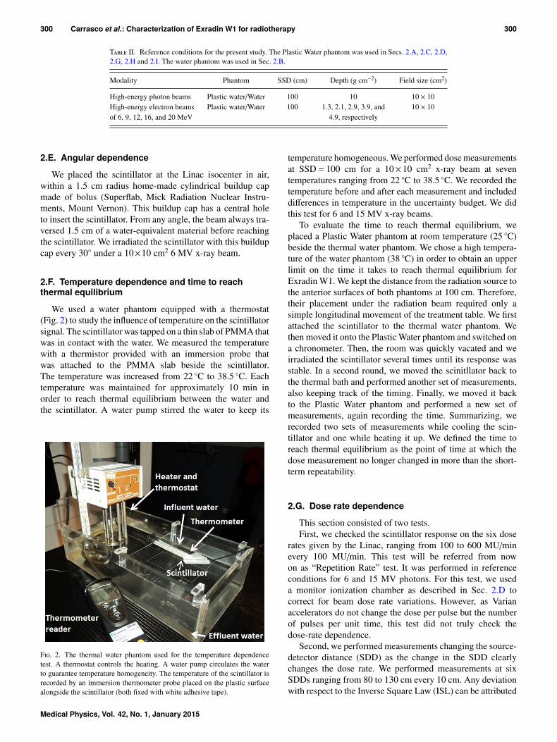
We used a water phantom equipped with a thermostat(Fig. 2) to study the influence of temperature on the scintillatorsignal. The scintillator was tapped on a thin slab of PMMA thatwas in contact with the water. We measured the temperaturewith a thermistor provided with an immersion probe thatwas attached to the PMMA slab beside the scintillator.The temperature was increased from 22 ◦C to 38.5 ◦C. Eachtemperature was maintained for approximately 10 min inorder to reach thermal equilibrium between the water andthe scintillator. A water pump stirred the water to keep its
F. 2. The thermal water phantom used for the temperature dependencetest. A thermostat controls the heating. A water pump circulates the waterto guarantee temperature homogeneity. The temperature of the scintillator isrecorded by an immersion thermometer probe placed on the plastic surfacealongside the scintillator (both fixed with white adhesive tape).
temperature homogeneous. We performed dose measurementsat SSD = 100 cm for a 10× 10 cm2 x-ray beam at seventemperatures ranging from 22 ◦C to 38.5 ◦C. We recorded thetemperature before and after each measurement and includeddifferences in temperature in the uncertainty budget. We didthis test for 6 and 15 MV x-ray beams.
To evaluate the time to reach thermal equilibrium, weplaced a Plastic Water phantom at room temperature (25 ◦C)beside the thermal water phantom. We chose a high tempera-ture of the water phantom (38 ◦C) in order to obtain an upperlimit on the time it takes to reach thermal equilibrium forExradin W1. We kept the distance from the radiation source tothe anterior surfaces of both phantoms at 100 cm. Therefore,their placement under the radiation beam required only asimple longitudinal movement of the treatment table. We firstattached the scintillator to the thermal water phantom. Wethen moved it onto the Plastic Water phantom and switched ona chronometer. Then, the room was quickly vacated and weirradiated the scintillator several times until its response wasstable. In a second round, we moved the scinitllator back tothe thermal bath and performed another set of measurements,also keeping track of the timing. Finally, we moved it backto the Plastic Water phantom and performed a new set ofmeasurements, again recording the time. Summarizing, werecorded two sets of measurements while cooling the scin-tillator and one while heating it up. We defined the time toreach thermal equilibrium as the point of time at which thedose measurement no longer changed in more than the short-term repeatability.
2.G. Dose rate dependence
This section consisted of two tests.First, we checked the scintillator response on the six dose
rates given by the Linac, ranging from 100 to 600 MU/minevery 100 MU/min. This test will be referred from nowon as “Repetition Rate” test. It was performed in referenceconditions for 6 and 15 MV photons. For this test, we useda monitor ionization chamber as described in Sec. 2.D tocorrect for beam dose rate variations. However, as Varianaccelerators do not change the dose per pulse but the numberof pulses per unit time, this test did not truly check thedose-rate dependence.
Second, we performed measurements changing the source-detector distance (SDD) as the change in the SDD clearlychanges the dose rate. We performed measurements at sixSDDs ranging from 80 to 130 cm every 10 cm. Any deviationwith respect to the Inverse Square Law (ISL) can be attributed
Medical Physics, Vol. 42, No. 1, January 2015
301 Carrasco et al.: Characterization of Exradin W1 for radiotherapy 301
to dose-rate dependence. On continuation, we refer to this testas the “ISL” test.
We performed the ISL test by placing the scintillator at theLinac isocenter in air with a buildup cap under a narrow beam(5×5 cm2). We investigated two buildup caps. First, we usedthe 1.5 cm radii cap made of bolus from Sec. 2.E for 6 MVx-ray beams only. This cap was not used for 15 MV as it didnot guarantee electron equilibrium for this energy. Second,we tried a 9.5 mm radius aluminium bronze alloy cap (5 cmwater equivalent thickness) for both 6 and 15 MV photons.As the uncertainty in the positioning of the detector under asmall field size at 80 cm has a direct impact on the result ofthis test, we performed two independent determinations andwe derived a positioning-related B-type uncertainty. This wasincluded in the reported uncertainty.
2.H. Water-equivalent depth of the effectivemeasurement point for x-ray beams
We placed the scintillator on the calibration plate and wemounted it onto a 12 cm slab phantom of Plastic Water toprovide backscatter. The SDD was set at 100 cm to the calibra-tion plate. Then, we measured TMRs for a 10×10 cm2 fieldfor 6 and 15 MV photon beams. We compared these TMRswith TMRs measured using the NACP chamber to estimatethe water-equivalent depth of the effective measurement pointof Exradin W1. Note that this geometry, with the scintillatoraxis perpendicular to the radiation beam, is not valid for fieldsizes less than 1.5×1.5 cm2.
2.I. Long-term stability
We derived long-term stability from the change in the cali-bration coefficient during the present study. The total accumu-lated dose was 127 kGy. We applied the temperature correc-tion factor obtained in Sec. 2.F.
2.J. Uncertainty budget
We defined an uncertainty budget including all depen-dencies except those we can correct (temperature effects andloss of sensitivity with accumulated dose). This overall uncer-tainty would therefore be the quadratic sum of these depen-dencies. We considered two scenarios: first, relative measure-ments considering the results of the previous tests and includ-ing the 0.7% maximum difference found by Guillot et al.3
to account for different field sizes; and second, referencedose measurements. For this second scenario, we included theuncertainties in dose calibration for the various modalities andenergies as detailed in TRS-398.10
3. RESULTS AND DISCUSSION3.A. Calibration
We verified that the electrometer software correction forCerenkov radiation was correctly implemented. The resultsof formulas (1) and (2) compared to the results from the
T III. Percentage differences between the dose measured using the scin-tillator calibrated at 6 MV x-rays and the dose measured using the ionizationchamber. The uncertainty is expressed with k = 1.
Modality Nominal energy Difference (%)
High-energy x-rays 6 MV —15 MV −0.2 ± 0.6
Electrons 6 MeV −0.5 ± 0.79 MeV −1.2 ± 0.6
12 MeV 0.5 ± 0.616 MeV −0.4 ± 0.620 MeV −0.2 ± 0.6
electrometer software were negligible (<0.06%) and due toelectrometer resolution.
3.B. Energy and modality dependence
Table III compares the dose measurements made by thescintillator with those made by the ionization chamber fordifferent modalities and energies. The third column showsthe percentage dose difference obtained using the calibrationcoefficient calculated for 6 MV x-rays without any furthercorrection. Differences were negligible taking into accountthe uncertainties with a coverage factor k = 2. We can affirmthat Exradin W1 shows an energy-independent response formegavoltage photon and electron beams. As the response ofthe scintillator was energy independent in this range, for allremaining sections except Sec. 2.H, we merged the data for 6MV and for 15 MV x-rays and we analyzed all data together.Any energy dependence is therefore also incorporated withinthe uncertainty budget.
Regarding CLR dependencies, for photon beams, changingthe length of the fiber exposed to scatter radiation had astrong impact on raw readings for both channels. However,this impact was not so strong on the CLR value, yieldinga standard deviation of only 0.5%. For all electron beams,CLRs obtained with the different methods and the differentenergies agreed within 0.9%. We used the average value of 15independent determinations (mostly for photon beams) andtook the 1.5% standard deviation from all CLR values intoaccount in its uncertainty.
As Table III shows, we obtained clinically acceptabledifferences (around or less than 1%) for high-energy x-raysand electron beams.
3.C. Short-term repeatability
Table IV shows the results when we performed an auto-matic triggered collection on channel 1. However, if thecollected charges were manually triggered, the result of thistest increased up to 0.40% ± 0.17% and 2.22% ± 0.17% for0.75 and 0.15 Gy, respectively. Due to the low currents, timingeffects are of paramount importance. We strongly recommenda dual electrometer with automatic triggered collection inorder to avoid the uncertainty related to poor repeatability thatbecomes unacceptable for dosimetry purposes at low doses.
Medical Physics, Vol. 42, No. 1, January 2015
302 Carrasco et al.: Characterization of Exradin W1 for radiotherapy 302
T IV. Main characteristics of Exradin W1. The uncertainty column includes all sources of uncertaintydescribed in Sec. 2 for each test, with the exception of temperature dependence and loss of sensitivity withaccumulated dose tests. For these tests, the statistical uncertainty in the slope of the least-square fit is shown. We
calculated the root-mean-square value (RMS) as RMS =
1/n�n
i=1 x2i
�, where “xi” are percentage deviations
from a reference value and i = 1 to n are all measurements within the corresponding test.
Test Result Uncertainty
Short-term repeatability (at 0.75 Gy) σ = 0.10% 0.07%Short-term repeatability (at 0.15 Gy) σ = 0.25% 0.05%Dose–response linearity RMS = 0.61% 0.20%Angular dependence RMS = 0.21% 0.07%Temperature dependence −0.225% ◦C−1 0.008% ◦C−1
Time to reach thermal equilibriuma 1 min 40 s 16 sRepetition rate dependence RMS = 0.53% 0.06%Deviation from ISL RMS = 0.38% 0.26%Loss of sensitivity with accumulated dose −0.28% kGy−1 (0–15 kGy)
−0.032% kGy−1 (15–127 kGy)0.06% kGy−1
0.018% kGy−1
aFor the conditions defined in Sec. 2.F.
The short-term repeatability obtained in this work was betterthan that reported by Lacroix et al.13 for an array of 29 plasticscintillator detectors embedded in a water-equivalent plasticsheet (0.8%), worse than that reported by Beddar et al.14 fora Bicron Co. BC-400 PSD (0.1%), and much lower than thatreported by Andersen et al.15 for a completely different kindof dosimeter like the Al2O3:C luminescence dosimetry system(1.3%).
3.D. Dose-response linearity
For most situations, the deviation from linearity was wellbelow 0.5%. However, there was a maximum deviation of−1.9% for a very low dose (0.075 Gy), leading to the RMSvalue shown in Table IV (0.61%). The result of this test withmanual triggered collection yielded worse results, reachingvalues as high as −10% for this very low dose. These effectsare also due to the timing effects. They can be avoided byincreasing the dose, and with an automatic trigger. An unex-pected finding, we observed when performing this test wasthat when environmental relative humidity levels were high(around 75%), leakage currents in the electrometer becamesignificant when measuring small doses. This value is consis-tent with the operating range given by the manufacturer16
(relative humidity between 20% and 80%).
3.E. Angular dependence
The maximum angular dependence was 0.34% ± 0.07%,only slightly larger than the RMS shown in Table IV. In thissection, the RMS value refers to percentage differences withrespect to the value measured at 0◦. The build-up cap used forthis test was home-made, adding an uncertainty of unknownmagnitude due to little flaws in its design. Consequently, theresult of this test must be taken as an upper limit. However,with the excellent result reported in Table IV, we can statethat Exradin W1 shows an almost isotropic response aroundits symmetry axis.
3.F. Temperature dependence and time to reachthermal equilibrium
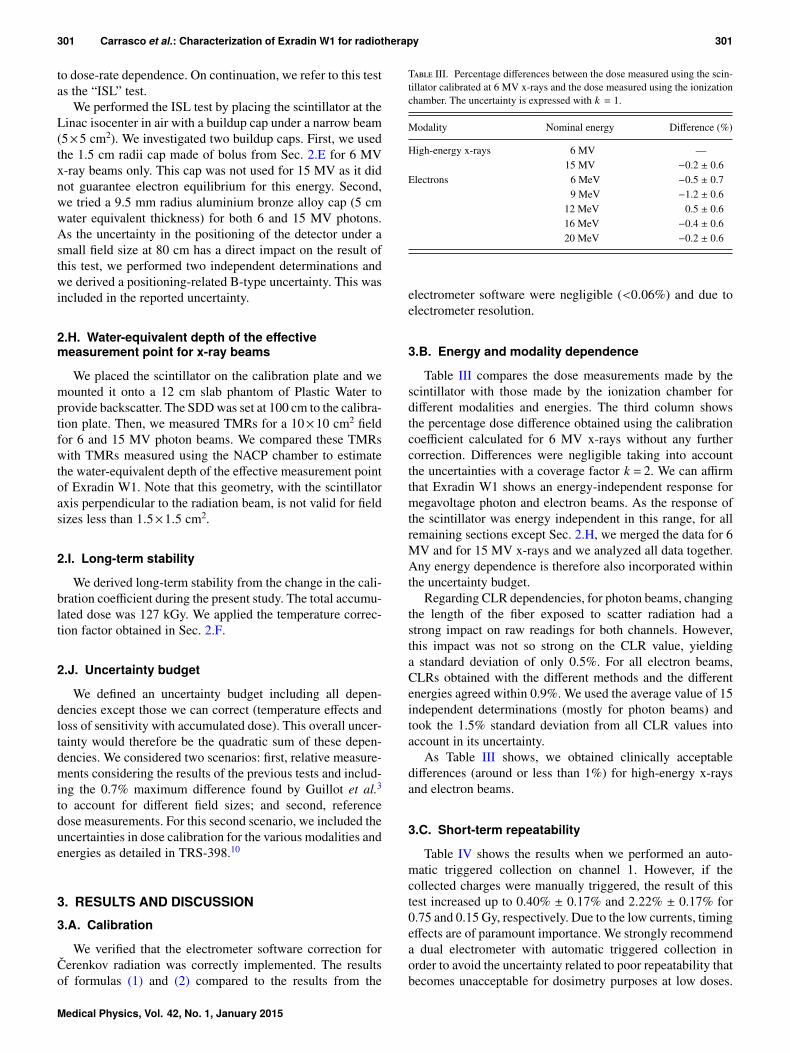
Temperature dependence is shown in Fig. 3 and summa-rized in Table IV. It is linear and almost of the same magnitudeas that observed for diodes17 but it has an opposite sign. Thedecrease in the light output was close to that obtained for aBCF-60 PSD (0.32% ◦C−1) by Wooton and Beddar.18 For abso-lute dose measurements, it should be included as a correctionfactor. Otherwise, the uncertainty would increase significantlyif the temperature was different from that at calibration, i.e., ina potential application for in-vivo dose measurements. Theresults of the present study confirm significant temperaturedependence, thus disagreeing with claims that PSDs responseis temperature independent19,20 and with the manufacturer’stechnical sheet.16
Figure 4 shows that after 40 s (the time to quickly leavethe treatment room and continue the irradiation), the readingdiffered 1% from the thermal equilibrium value, after 1 min,
F. 3. Temperature dependence of Exradin W1. The points in the graphrepresent the percentage dose difference measured for each temperature withrespect to that measured at 22 ◦C. The data show a linear behavior with acorrelation coefficient of 0.999. The slope of the fit is shown in Table V.
Medical Physics, Vol. 42, No. 1, January 2015
303 Carrasco et al.: Characterization of Exradin W1 for radiotherapy 303
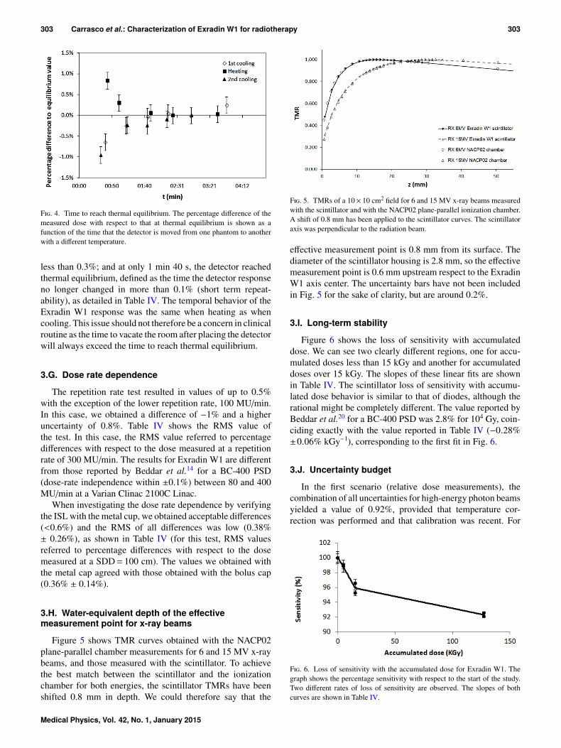
F. 4. Time to reach thermal equilibrium. The percentage difference of themeasured dose with respect to that at thermal equilibrium is shown as afunction of the time that the detector is moved from one phantom to anotherwith a different temperature.
less than 0.3%; and at only 1 min 40 s, the detector reachedthermal equilibrium, defined as the time the detector responseno longer changed in more than 0.1% (short term repeat-ability), as detailed in Table IV. The temporal behavior of theExradin W1 response was the same when heating as whencooling. This issue should not therefore be a concern in clinicalroutine as the time to vacate the room after placing the detectorwill always exceed the time to reach thermal equilibrium.
3.G. Dose rate dependence
The repetition rate test resulted in values of up to 0.5%with the exception of the lower repetition rate, 100 MU/min.In this case, we obtained a difference of −1% and a higheruncertainty of 0.8%. Table IV shows the RMS value ofthe test. In this case, the RMS value referred to percentagedifferences with respect to the dose measured at a repetitionrate of 300 MU/min. The results for Exradin W1 are differentfrom those reported by Beddar et al.14 for a BC-400 PSD(dose-rate independence within ±0.1%) between 80 and 400MU/min at a Varian Clinac 2100C Linac.
When investigating the dose rate dependence by verifyingthe ISL with the metal cup, we obtained acceptable differences(<0.6%) and the RMS of all differences was low (0.38%± 0.26%), as shown in Table IV (for this test, RMS valuesreferred to percentage differences with respect to the dosemeasured at a SDD= 100 cm). The values we obtained withthe metal cap agreed with those obtained with the bolus cap(0.36% ± 0.14%).
3.H. Water-equivalent depth of the effectivemeasurement point for x-ray beams
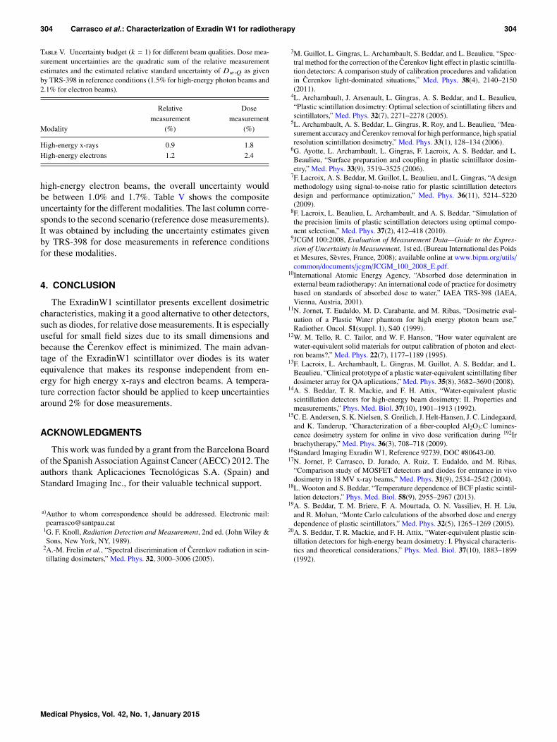
Figure 5 shows TMR curves obtained with the NACP02plane-parallel chamber measurements for 6 and 15 MV x-raybeams, and those measured with the scintillator. To achievethe best match between the scintillator and the ionizationchamber for both energies, the scintillator TMRs have beenshifted 0.8 mm in depth. We could therefore say that the
F. 5. TMRs of a 10× 10 cm2 field for 6 and 15 MV x-ray beams measuredwith the scintillator and with the NACP02 plane-parallel ionization chamber.A shift of 0.8 mm has been applied to the scintillator curves. The scintillatoraxis was perpendicular to the radiation beam.
effective measurement point is 0.8 mm from its surface. Thediameter of the scintillator housing is 2.8 mm, so the effectivemeasurement point is 0.6 mm upstream respect to the ExradinW1 axis center. The uncertainty bars have not been includedin Fig. 5 for the sake of clarity, but are around 0.2%.
3.I. Long-term stability
Figure 6 shows the loss of sensitivity with accumulateddose. We can see two clearly different regions, one for accu-mulated doses less than 15 kGy and another for accumulateddoses over 15 kGy. The slopes of these linear fits are shownin Table IV. The scintillator loss of sensitivity with accumu-lated dose behavior is similar to that of diodes, although therational might be completely different. The value reported byBeddar et al.20 for a BC-400 PSD was 2.8% for 104 Gy, coin-ciding exactly with the value reported in Table IV (−0.28%±0.06% kGy−1), corresponding to the first fit in Fig. 6.
3.J. Uncertainty budget
In the first scenario (relative dose measurements), thecombination of all uncertainties for high-energy photon beamsyielded a value of 0.92%, provided that temperature cor-rection was performed and that calibration was recent. For
F. 6. Loss of sensitivity with the accumulated dose for Exradin W1. Thegraph shows the percentage sensitivity with respect to the start of the study.Two different rates of loss of sensitivity are observed. The slopes of bothcurves are shown in Table IV.
Medical Physics, Vol. 42, No. 1, January 2015
304 Carrasco et al.: Characterization of Exradin W1 for radiotherapy 304
T V. Uncertainty budget (k = 1) for different beam qualities. Dose mea-surement uncertainties are the quadratic sum of the relative measurementestimates and the estimated relative standard uncertainty of Dw,Q as givenby TRS-398 in reference conditions (1.5% for high-energy photon beams and2.1% for electron beams).
Modality
Relativemeasurement
(%)
Dosemeasurement
(%)
High-energy x-rays 0.9 1.8High-energy electrons 1.2 2.4
high-energy electron beams, the overall uncertainty wouldbe between 1.0% and 1.7%. Table V shows the compositeuncertainty for the different modalities. The last column corre-sponds to the second scenario (reference dose measurements).It was obtained by including the uncertainty estimates givenby TRS-398 for dose measurements in reference conditionsfor these modalities.
4. CONCLUSION
The ExradinW1 scintillator presents excellent dosimetriccharacteristics, making it a good alternative to other detectors,such as diodes, for relative dose measurements. It is especiallyuseful for small field sizes due to its small dimensions andbecause the Cerenkov effect is minimized. The main advan-tage of the ExradinW1 scintillator over diodes is its waterequivalence that makes its response independent from en-ergy for high energy x-rays and electron beams. A tempera-ture correction factor should be applied to keep uncertaintiesaround 2% for dose measurements.
ACKNOWLEDGMENTS
This work was funded by a grant from the Barcelona Boardof the Spanish Association Against Cancer (AECC) 2012. Theauthors thank Aplicaciones Tecnológicas S.A. (Spain) andStandard Imaging Inc., for their valuable technical support.
a)Author to whom correspondence should be addressed. Electronic mail:[email protected]
1G. F. Knoll, Radiation Detection and Measurement, 2nd ed. (John Wiley &Sons, New York, NY, 1989).
2A.-M. Frelin et al., “Spectral discrimination of Cerenkov radiation in scin-tillating dosimeters,” Med. Phys. 32, 3000–3006 (2005).
3M. Guillot, L. Gingras, L. Archambault, S. Beddar, and L. Beaulieu, “Spec-tral method for the correction of the Cerenkov light effect in plastic scintilla-tion detectors: A comparison study of calibration procedures and validationin Cerenkov light-dominated situations,” Med. Phys. 38(4), 2140–2150(2011).
4L. Archambault, J. Arsenault, L. Gingras, A. S. Beddar, and L. Beaulieu,“Plastic scintillation dosimetry: Optimal selection of scintillating fibers andscintillators,” Med. Phys. 32(7), 2271–2278 (2005).
5L. Archambault, A. S. Beddar, L. Gingras, R. Roy, and L. Beaulieu, “Mea-surement accuracy and Cerenkov removal for high performance, high spatialresolution scintillation dosimetry,” Med. Phys. 33(1), 128–134 (2006).
6G. Ayotte, L. Archambault, L. Gingras, F. Lacroix, A. S. Beddar, and L.Beaulieu, “Surface preparation and coupling in plastic scintillator dosim-etry,” Med. Phys. 33(9), 3519–3525 (2006).
7F. Lacroix, A. S. Beddar, M. Guillot, L. Beaulieu, and L. Gingras, “A designmethodology using signal-to-noise ratio for plastic scintillation detectorsdesign and performance optimization,” Med. Phys. 36(11), 5214–5220(2009).
8F. Lacroix, L. Beaulieu, L. Archambault, and A. S. Beddar, “Simulation ofthe precision limits of plastic scintillation detectors using optimal compo-nent selection,” Med. Phys. 37(2), 412–418 (2010).
9JCGM 100:2008, Evaluation of Measurement Data—Guide to the Expres-sion of Uncertainty in Measurement, 1st ed. (Bureau International des Poidset Mesures, Sèvres, France, 2008); available online at www.bipm.org/utils/common/documents/jcgm/JCGM_100_2008_E.pdf.
10International Atomic Energy Agency, “Absorbed dose determination inexternal beam radiotherapy: An international code of practice for dosimetrybased on standards of absorbed dose to water,” IAEA TRS-398 (IAEA,Vienna, Austria, 2001).
11N. Jornet, T. Eudaldo, M. D. Carabante, and M. Ribas, “Dosimetric eval-uation of a Plastic Water phantom for high energy photon beam use,”Radiother. Oncol. 51(suppl. 1), S40 (1999).
12W. M. Tello, R. C. Tailor, and W. F. Hanson, “How water equivalent arewater-equivalent solid materials for output calibration of photon and elect-ron beams?,” Med. Phys. 22(7), 1177–1189 (1995).
13F. Lacroix, L. Archambault, L. Gingras, M. Guillot, A. S. Beddar, and L.Beaulieu, “Clinical prototype of a plastic water-equivalent scintillating fiberdosimeter array for QA aplications,” Med. Phys. 35(8), 3682–3690 (2008).
14A. S. Beddar, T. R. Mackie, and F. H. Attix, “Water-equivalent plasticscintillation detectors for high-energy beam dosimetry: II. Properties andmeasurements,” Phys. Med. Biol. 37(10), 1901–1913 (1992).
15C. E. Andersen, S. K. Nielsen, S. Greilich, J. Helt-Hansen, J. C. Lindegaard,and K. Tanderup, “Characterization of a fiber-coupled Al2O3:C lumines-cence dosimetry system for online in vivo dose verification during 192Irbrachytherapy,” Med. Phys. 36(3), 708–718 (2009).
16Standard Imaging Exradin W1, Reference 92739, DOC #80643-00.17N. Jornet, P. Carrasco, D. Jurado, A. Ruiz, T. Eudaldo, and M. Ribas,
“Comparison study of MOSFET detectors and diodes for entrance in vivodosimetry in 18 MV x-ray beams,” Med. Phys. 31(9), 2534–2542 (2004).
18L. Wooton and S. Beddar, “Temperature dependence of BCF plastic scintil-lation detectors,” Phys. Med. Biol. 58(9), 2955–2967 (2013).
19A. S. Beddar, T. M. Briere, F. A. Mourtada, O. N. Vassiliev, H. H. Liu,and R. Mohan, “Monte Carlo calculations of the absorbed dose and energydependence of plastic scintillators,” Med. Phys. 32(5), 1265–1269 (2005).
20A. S. Beddar, T. R. Mackie, and F. H. Attix, “Water-equivalent plastic scin-tillation detectors for high-energy beam dosimetry: I. Physical characteris-tics and theoretical considerations,” Phys. Med. Biol. 37(10), 1883–1899(1992).
Medical Physics, Vol. 42, No. 1, January 2015


![WHITEHALL - Isprava€¦ · BATH ROOM -2 W1 W1 W1 W1 W1 W1 D1 D1 D1 D1 5093 [16'-9"] DN. 6' W 2450 [8'] 2761 [9'-1"] 3714 [12'-2"] 10800 [35'-5"] 7679 [25'-2"] 1800 [5'-11"] 5316](https://img.pdfslide.us/doc/110x75/5f78627116e891416e53a754/whitehall-isprava-bath-room-2-w1-w1-w1-w1-w1-w1-d1-d1-d1-d1-5093-16-9.jpg)