Embed Size (px)
Citation preview

Research ArticleCharacterization of the Aerodynamic Ground Effect andIts Influence in Multirotor Control
Pedro Sanchez-Cuevas, Guillermo Heredia, and Anibal Ollero
Robotics, Vision and Control Group, University of Seville, Seville, Spain
Correspondence should be addressed to Guillermo Heredia; [email protected]
Received 14 February 2017; Revised 6 July 2017; Accepted 13 July 2017; Published 17 August 2017
Academic Editor: Kenneth M. Sobel
Copyright © 2017 Pedro Sanchez-Cuevas et al. This is an open access article distributed under the Creative Commons AttributionLicense, which permits unrestricted use, distribution, and reproduction in any medium, provided the original work is properlycited.
This paper analyzes the ground effect in multirotors, that is, the change in the thrust generated by the rotors when flying close tothe ground due to the interaction of the rotor airflow with the ground surface. This effect is well known in single-rotor helicoptersbut has been assumed erroneously to be similar for multirotors in many cases in the literature. In this paper, the ground effect formultirotors is characterized with experimental tests in several cases and the partial ground effect, a situation in which one or someof the rotors of the multirotor (but not all) are under the ground effect, is also characterized. The influence of the different cases ofground effect in multirotor control is then studied with several control approaches in simulation and validated with experimentsin a test bench and with outdoor flights.
1. Introduction
In the last years, there has been a growing interest inUnmanned Aerial Vehicles (UAVs) [1]. UAVs of differentsizes have been used in applications such as exploration,detection, precise localization, monitoring, and measuringthe evolution of natural disasters. However, in most ofthese applications, the aerial robots are mainly considered asplatforms for environment sensing. Then, the aerial robotsdo not modify the state of the environment and there are nophysical interactions between the UAV and the environment.Furthermore, the interactions between the UAVs themselvesare essentially information exchanges, without physical cou-plings between them.
Recently, the development of autonomous aerial robotswith integrated robotic manipulators is catching much inter-est in robotic research [2, 3]. These aerial manipulators [4–6], as they are usually known, extend the range of possibleapplications of UAVs. For instance, aerial manipulators canbe used for the inspection and maintenance of industrialplants and infrastructures [7], aerial power lines, andmovingobjects [8] and taking samples of material from areas that aredifficult to access.
Aerial robotic manipulation with multirotors usuallyinvolves flying near objects, structures, and other obstacles,for example, to grasp or manipulate objects that are on theground, over surfaces, near walls, or even under a surface.In all these cases, the multirotors will operate in hover orlow speed near these horizontal or vertical surfaces. Thispaper studies the control of multirotor platforms under theinfluence of close ground surfaces onmultirotors rotor thrust.Thus, for example, in the AEROARMS European project[9], aerial manipulators with multiple arms are used forinspection and maintenance in industrial settings and flyingclose to horizontal surfaces, and in the ARCAS Europeanproject [10], aerial robotic manipulation for assembly over asurface is considered (see Figure 1).
The wake of a rotorcraft can be greatly affected when therotor is close to obstacles that disturb its free development.Themost common of these effects is the one produced by theground surface. This phenomenon, usually known as groundeffect, is more pronounced in rotorcraft operating in hoverand low speed. For rotorcraft hovering close to the ground,the rotor wake must rapidly expand as it approaches thesurface, transitioning from the almost vertical downwash toradial outwash parallel to the ground. This alters the velocity
HindawiInternational Journal of Aerospace EngineeringVolume 2017, Article ID 1823056, 17 pageshttps://doi.org/10.1155/2017/1823056

2 International Journal of Aerospace Engineering
Figure 1: Structure assembly in the ARCAS project.
of the slipstream and the induced velocity, which then affectsthe rotor thrust and power. The ground effect in helicoptershas been well researched in literature [11, 12] and has beenstudied for take-off, landing, and hovering near the ground[13–15]. However, for multirotors, it has not received muchattention yet, although these platforms are being increasinglyused in multiple applications.
The influence of ground effect in helicopters has beenstudied through the use of an underlying aerodynamicmodelor empirically. A classical analytical model for the groundeffect is provided by [11], using potential flow with a singlesource to model the rotor airflow and the method of imagesto account for the ground effect. Other authors have providedempirical expressions for the rotor thrust increment inground effect for large [16] and small UAV helicopters [17].The model in [11] has been widely used because it has asimple analytical form and has been experimentally shownto accurately capture the relationship between rotor thrust inground effect and rotor height over the ground surface.
The ground effect in multirotors has received much lessattention. Several papers deal with the aerodynamic modelsof multirotors [18], which are used for navigation [19] or evenfor power control [20]. Disturbance observers have becomepopular in the last years for estimating external wrench inmultirotors [21, 22]. In most cases, it is assumed that theexternal disturbance source is unique, mainly contact forces[23, 24] or wind. In [25], the simultaneous online estimationof aerodynamic and contact forces is studied to discriminatebetween them and compute the wind velocity by means ofmodel inversion. However, disturbance observers have notbeen used for ground effect estimation.
The influence of ground effect has been considered inthe development of controllers for low-altitude flight in [26]using an adaptive controller and a height estimator that workswell in the experiments, although false measurement fromthe ultrasonic sensor can destabilize the system. A take-off and landing controller that uses an ant colony filter forestimation of the ground effect is presented in [27]. Thealgorithm is tested in simulation with PID and sliding modescontrollers, and in both cases the consideration of the groundeffect improves significantly the controller performance. In[28], a PID landing controller with a ground effect robustcompensator has been presented. The experimental testsshow that accounting for the ground effect improves the
controller behavior. Also, ground effect estimation using avision sensor to estimate distance to obstacles and learningfrom previous flights have also been proposed [29]. Adynamic controller for rotorcraft landing and hovering inground effect using feedback control based on flow fieldestimation has also been developed and tested in simulation[30].
However, in almost all cases, the model of the groundeffect in [11] is assumed or evaluated for a single rotor. Theonly experimental results that have been reported, makingexperiments with a small quadrotor flying in hover over theground at different heights [31] and using a test bench [32],suggest that the ground effect in multirotors may be largerthan predicted by [11], although the issue has not been furtheranalyzed.
This paper studies the influence of the ground effect inmultirotor control, considering the full multirotor and notonly an isolated rotor. Then, the effects of all the rotors ofthe multirotor being under the ground effect are analyzed.Furthermore, a phenomenon that we have called multirotorpartial ground effect is described and analyzed. It appearsonly in multirotors when flying close to surfaces or objectsin the environment, in situations where some of the rotorsexperiment the ground effect but not all. To the authors’knowledge, this is the first time that the aerodynamic partialground effect is reported in the literature.
A test bench has been built to determine experimentallythe influence of proximity to these surfaces of the individualrotors in a multirotor and of the whole multirotor. In thepaper, the results of these experiments are presented.
The organization of the rest of the paper is as follows:Section 2 presents the analysis of the ground effect for asingle rotor and the full multirotor and when only some ofthe rotors are under the ground effect, using experimentalresults in the test bench. Section 3 studies the implicationsof flying near surfaces for multirotor control, presentingsimulations of different control strategies in ground effect.These control strategies include a standard linear controller,whose behavior is used as baseline for comparison, and twocontrollers that consider the ground effect: a controller thatuses an external wrench disturbance observer for groundeffect estimation and a controller that estimates ground effectfrom the model of the environment. Section 4 presentsseveral experiments withmultirotors in a test stand and flying
International Journal of Aerospace Engineering 3
outdoors which show the ground effect and the performanceof the controllers.
2. The Ground Effect in Rotary Wing UAVs
2.1. Ground Effect for Single Rotor. As mentioned before, theground effect for single-rotor helicopters has been extensivelystudied in the literature [11–16]. When the rotor is under theground effect, there is an increment in the thrust generatedby the rotor for the same power, which is greater the closerthe rotor is to the ground. In general, the ground effect inhelicopters has been found to be significant when the rotoris at a vertical distance to the ground of up to one rotordiameter. A simple analytical model that is used to modelthe ground effect in helicopters uses potential flow with asingle source to model the rotor airflow and the method ofimages to model the ground effect (potential flow with themethod of images (PFI)) [11]. Other authors have presentedempirical expressions for the increment of rotor thrust inground effect which show similar results [16, 17], althoughthe PFI model in [11] has been widely used because it has asimple analytical form and has been experimentally shownto accurately capture the relationship between rotor thrust inground effect and rotor height over the ground surface.
The PFI model represents the rotor as a three-dimensional potential source, which has a strength of𝑠 = 𝑅2VIGE/4, where R is the radius of the rotor and VIGE isthe induced velocity at the rotor. The velocity potential of asource placed at (𝑥0, 𝑦0, 𝑧0) can be expressed as
𝜙 = − 𝑠√(𝑥 − 𝑥0)2 + (𝑦 − 𝑦0)2 + (𝑧 − 𝑧0)2 . (1)
The effect of the ground plane is modelled as a mirror-image source to enforce that the flow does not pass throughthe ground plane.Thus, placing two sources in 𝑥0 = 0, 𝑦0 = 0,and ±𝑧 and obtaining the ratio of air velocities in-ground-effect (IGE) and out-of-ground-effect (OGE), the followingexpression for the rotor thrust increment due to the groundeffect can be derived [11]:𝑇IGE𝑇OGE
= 11 − (𝑅/4𝑧)2 , (2)
where 𝑇OGE is the thrust generated by the rotor flying out ofthe ground effect, 𝑇IGE is the thrust when the rotor is underthe ground effect, 𝑅 is the radius of the rotor, and z is thevertical distance of the rotor to the ground.
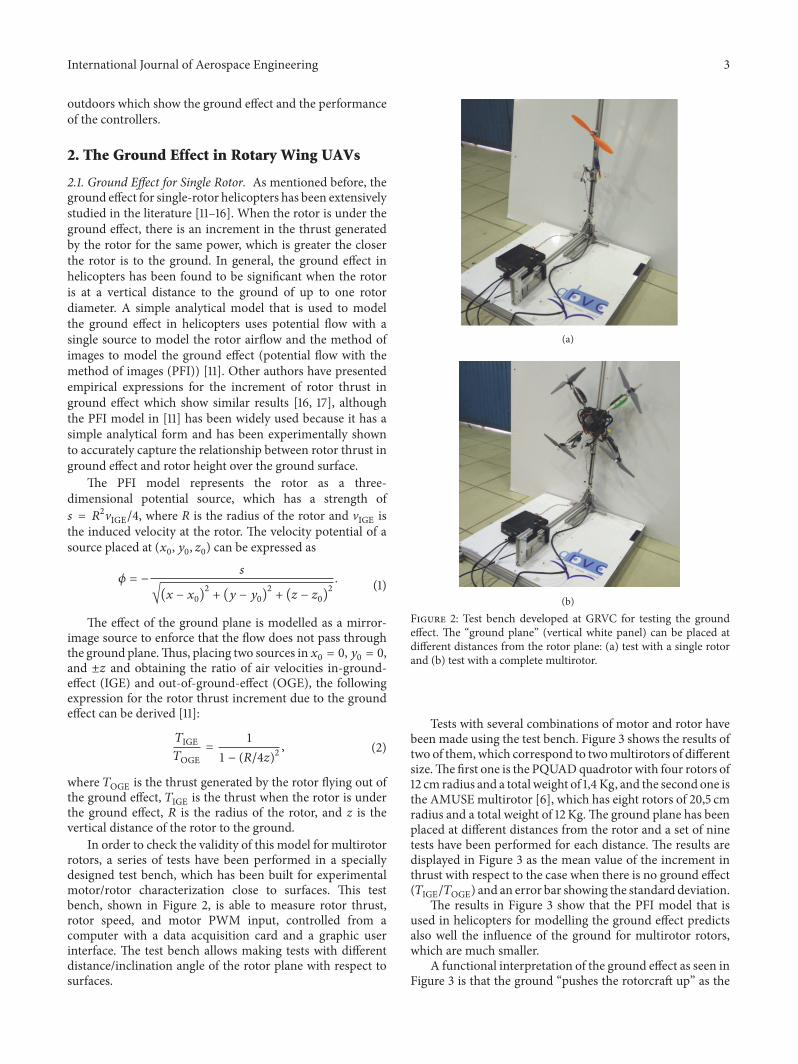
In order to check the validity of this model for multirotorrotors, a series of tests have been performed in a speciallydesigned test bench, which has been built for experimentalmotor/rotor characterization close to surfaces. This testbench, shown in Figure 2, is able to measure rotor thrust,rotor speed, and motor PWM input, controlled from acomputer with a data acquisition card and a graphic userinterface. The test bench allows making tests with differentdistance/inclination angle of the rotor plane with respect tosurfaces.
(a)
(b)Figure 2: Test bench developed at GRVC for testing the groundeffect. The “ground plane” (vertical white panel) can be placed atdifferent distances from the rotor plane: (a) test with a single rotorand (b) test with a complete multirotor.
Tests with several combinations of motor and rotor havebeen made using the test bench. Figure 3 shows the results oftwo of them,which correspond to twomultirotors of differentsize.The first one is the PQUADquadrotor with four rotors of12 cm radius and a total weight of 1,4 Kg, and the second one isthe AMUSEmultirotor [6], which has eight rotors of 20,5 cmradius and a total weight of 12 Kg.The ground plane has beenplaced at different distances from the rotor and a set of ninetests have been performed for each distance. The results aredisplayed in Figure 3 as the mean value of the increment inthrust with respect to the case when there is no ground effect(𝑇IGE/𝑇OGE) and an error bar showing the standard deviation.
The results in Figure 3 show that the PFI model that isused in helicopters for modelling the ground effect predictsalso well the influence of the ground for multirotor rotors,which are much smaller.
A functional interpretation of the ground effect as seen inFigure 3 is that the ground “pushes the rotorcraft up” as the

4 International Journal of Aerospace Engineering
Ground e�ect
1
1.05
1.1
1.15
1.2
1.25
T)'
%/T
/'%
31.5 2.5 3.50.5 1 2 4z/R
Figure 3: Ground effect for a single rotor: experimental andtheoretical results of the increment in the thrust generated by asingle rotor as a function of the distance to the ground plane. Blackdashes lines represent the results of the PFI model. Blue error baris the experimental result for PQUAD and orange error bar is theexperimental result for AMUSE.
rotor approaches the surface. For the same transmitted powerto the motor, the rotor develops more thrust caused only by
the presence of the ground,which deviates the airflow radiallyand parallel to the ground, generating new fields of velocityand pressure around the rotor.
2.2. Ground Effect for the Full Multirotor. Unlike helicoptersthat have a single main rotor, in multirotors, the presence ofmultiple coplanar rotors may induce different behavior withrespect to the single-rotor case, since the airflows from thedifferent rotors may interfere with each other. An analyticalmodel of the ground effect obtained using potential flow andthe method of images for a full multirotor has been derived,following the same assumptions of the PFI for a single rotorshown in the previous subsection. The potential flow modeluses one source located at the geometric center of each rotorand its corresponding image source to represent the groundboundary conditions. So, the four rotors and four imageswill be modelled, placing three dimensional sources in thesame way as the previous section. For the case of a quadrotorwith four coplanar rotors with a separation d from each rotoraxis to its adjacent rotor axes, the sources of the rotors andits images will be 𝜙1,5 : (0, 0, ±𝑧), 𝜙2,6 : (0, 𝑑, ±𝑧), 𝜙3,7 :(𝑑, 0, ±𝑧), and 𝜙4,8 : (𝑑, 𝑑, ±𝑧), where 𝜙𝑖,𝑖+4 represents thevelocity potentials of the rotor 𝑖 and its rotor image (𝑖 + 4).Thus, the resultant expression of the increment in thrust dueto the ground effect is the following:
𝑇IGE𝑇OGE= 11 − (𝑅/4𝑧)2 − 𝑅2 (𝑧/√(𝑑2 + 4𝑧2)3) − (𝑅2/2) (𝑧/√(2𝑑2 + 4𝑧2)3) . (3)
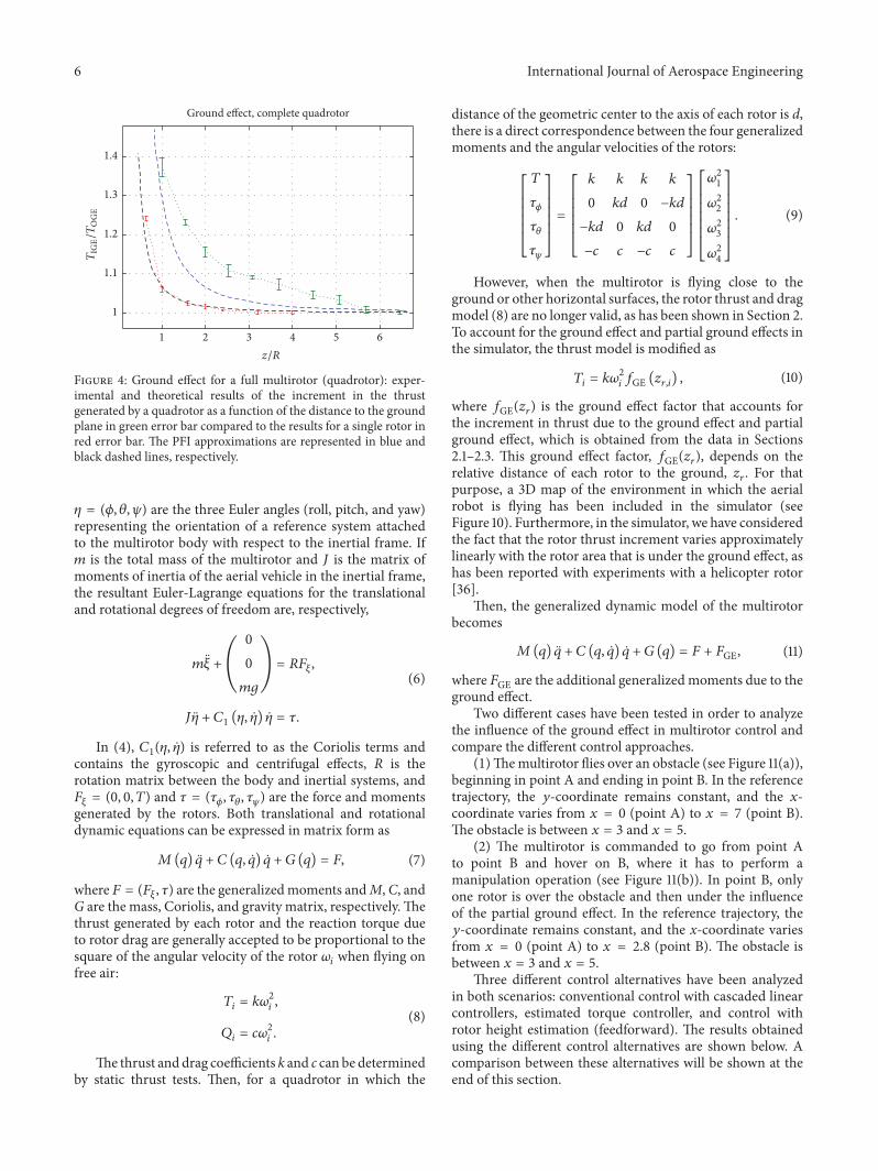
Figure 4 shows the increment in thrust for a quadrotordue to the ground effect with a dashed line and for a singlerotor with a solid line for comparison. It can be seen thatthe effect is significantly larger for a quadrotor due to theaerodynamic interference of the other rotors (the additionalterms in the denominator of (3)).
Furthermore, experimental tests with a full quadrotorhave also been performed using the test bench describedabove. In this case, the tests have been done with the PQUADquadrotor shown in Figure 2(b), and the results can be seenin Figure 4. Similar to the single-rotor case, five tests havebeen done at each distance to the ground, and the averagevalues are marked with a red circle and a blue error barrepresents the standard deviation. The experimental resultsin Figure 4 give values for the ground effect thrust increasewhich are significantly larger than the predicted ones withthe PFI quadrotor model (dashed line) and the results for asingle rotor. A possible explanation for this larger effect in thefull multirotor is what is known as the fountain effect, whicharises when a pair of rotors are flying close to the ground.This can lead to strong flow interactions of the slipstreamflow between the rotors. The airflow of each rotor splaysout radially in all directions when it encounters the groundplane, but in the area between the rotors it interacts withthe flow of the other rotor and the flow reverses back upthrough the rotors, impinging on the central part of the
quadrotor body, increasing the upward force acting on theaerial vehicle due to the ground effect. This effect has beenreported for tandem helicopters [33] and has been suggestedalso for quadrotors [32]. Figure 5 shows a CFD simulationthat illustrates this fountain effect. This simulation has beendone using a simplified model of a quadrotor hovering ata distance of 2R (with a rotor radius R of 12 cm for thesimulation) from the ground plane. The rotors have beenmodelled as a constant velocity source on the rotor area, thatis, the rotation of the propeller is not being simulated. Thevelocity of the constant velocity source is the mean valueof the airspeed measured experimentally under the rotorsof the PQUAD quadrotor flying in hover. The central partof the quadrotor body has been modelled with a solid box.Figure 5 shows the velocity field in a vertical plane cut alongthe quadrotor diagonal. It can be seen in this figure thatthe airflow coming out from the rotors, instead of spreadingparallel to the ground in all directions as in the outer part ofrotors 1 and 3, interacts with the ground and the central bodyin the central area between both rotors, forming a vortex ringthat causes the fountain effect with the increase of the thrustdue to the ground effect.
The PFI quadrotor model of (3) does not reproduce thebehavior observed in the experiments. Since it is very usefulto have a simplified model of the ground effect in multirotors

International Journal of Aerospace Engineering 5
that can be used for simulations and controller development,an additional term has been included in the equation toaccount for flow recirculation and the central body lift thatit generates. This additional term uses the velocity of the air
at the central point of the body and adjusts its influence withan empirical coefficient 𝐾𝑏, which takes a value close to 2 inthe experiments performed.Then the expression of the thrustincrement due to the ground effect takes the following form:
𝑇IGE𝑇OGE= 11 − (𝑅/4𝑧)2 − 𝑅2 (𝑧/√(𝑑2 + 4𝑧2)3) − (𝑅2/2) (𝑧/√(2𝑑2 + 4𝑧2)3) − 2𝑅2 (𝑧/√(𝑏2 + 4𝑧2)3)𝐾𝑏 , (4)
where b is the distance between two opposite rotor axes(diagonal) and 𝐾𝑏 is the empirical body lift coefficient.Figure 6 shows the thrust increment due to the ground effectgiven by the multirotor PFI with the body lift term, with𝐾𝑏 = 2. As can be seen in the figure, expression (4) matchesmore closely the experimental values.
As a conclusion, although the ground effect in multiro-tors (multiple coplanar rotors) has been assumed by mostresearchers to be the same as for helicopters (a single rotor)[18–29] and be significant up to distances to the ground of 2rotor radii, the results presented in this section show clearlythat this is not the case; the ground effect for multirotors ismuch larger, being significant for distances to the groundof up to 5 rotor radii. Although the PFI can be expandedto include the contributions of all the rotors of a quadrotor(see (3)), the addition of a body lift term with an empiricalcoefficient (see (4)) reproduces the experimental behaviorand can be used in simulations and controller development.
2.3. Partial Ground Effect. A new phenomenon that appearsin aerial manipulation with multirotors when approachingsome locations in the environment to manipulate objects iswhat we called multirotor partial ground effect. In the partialground effect (see Figure 7 for a quadrotor), which is uniquetomultirotors, themultirotor is flying in hover or at low speedin a situation inwhich only one or several of its rotors (but notall) are under the influence of the ground effect. In this situa-tion, rotor 3 in Figure 7 will experiment an increase in thrustΔ𝑇ge1 which will generate a disturbing moment𝑀ge1 whichtries to rotate themultirotor counterclockwise and thenmoveapart from the object because of the tilting. This effect mayinduce an important disturbance, and its implications inmultirotor control will be analyzed in the next sections.
If one of the rotors is under the ground effect, itscharacterization can be modelled as described in Section 2.1.However, the case when three of the rotors are close to ahorizontal surface under the ground effect will be different.For this case, a similar analysis to the full multirotor hasbeen made, including the PFI analytical model and theexperimental tests in the test bench with a quadrotor withonly three rotors switched on. The results are shown inFigure 8, where the ground effect is much larger than that fora single rotor and follows the same trend as that for the fullmultirotor, though with less intensity.
2.4. Response to Attitude Disturbances. Another consequenceof the ground effect which is also unique tomultirotors comes
from the way the rotor thrust forces vary with the distanceto the ground. In Figure 9, a multirotor hovering in groundeffect which experiments an attitude perturbation is shown.Since the increment in rotor thrust depends on the distanceof each rotor to the ground and each rotor has a different dis-tance (𝑧1 and 𝑧3 in Figure 9), a disturbancemoment𝑀ge2 willbe generatedwhich tries to rotate themultirotor opposing thedisturbance, and, thus, it is a stabilizing moment.
In practice, however, it has been found that for typicalattitude disturbances of about 5–10∘ this effect, althoughstabilizing, is not considerable unless the multirotor is veryclose to the ground, and then it is considered not significantfor controller development.
3. Influence of Proximity to Surfaces inMultirotor Control
This section analyzes the influence of flying close to surfaceson multirotor control. Partial ground effect is a specialphenomenon that appears only in multirotors when flyingclose to surfaces and can be defined as situations in whichonly some of the rotors (but not all) are under the groundeffect. We study the control of the partial ground effectbecause it is the most related to the practice of aerialmanipulation. The section includes a comparative study ofthe results obtained in simulation tests of different controlstrategies of a quadrotor model. The tests have been madesimulating that the multirotor is under the influence of theground effect and using the ground effect model presented inthe previous section.
3.1. Multirotor Dynamic Model. The dynamic model ofthe multirotor can be obtained using the Euler-Lagrangeformulation [34, 35]. This model is basically obtained byconsidering the multirotor as a rigid body evolving in 3Dspace and subject to one force (the total thrust generated byal the rotors) and threemoments generated by the differencesin speed and thrust of pairs of rotors. The dynamics of theelectric motors are relatively fast and therefore they will beneglected as well as the flexibility of the blades.
The generalized coordinates of the multirotor can bedefined as
𝑞 = (𝑥, 𝑦, 𝑧, 𝜙, 𝜃, 𝜓) , (5)
where 𝜉 = (𝑥, 𝑦, 𝑧) denote the position of the center ofmass of the multirotor relative to the inertial frame and
6 International Journal of Aerospace Engineering
Ground e�ect, complete quadrotor
1
1.1
1.2
1.3
1.4
T)'
%/T
/'%
3 6521 4z/R
Figure 4: Ground effect for a full multirotor (quadrotor): exper-imental and theoretical results of the increment in the thrustgenerated by a quadrotor as a function of the distance to the groundplane in green error bar compared to the results for a single rotor inred error bar. The PFI approximations are represented in blue andblack dashed lines, respectively.
𝜂 = (𝜙, 𝜃, 𝜓) are the three Euler angles (roll, pitch, and yaw)representing the orientation of a reference system attachedto the multirotor body with respect to the inertial frame. If𝑚 is the total mass of the multirotor and 𝐽 is the matrix ofmoments of inertia of the aerial vehicle in the inertial frame,the resultant Euler-Lagrange equations for the translationaland rotational degrees of freedom are, respectively,
𝑚 𝜉 + ( 00𝑚𝑔) = 𝑅𝐹𝜉,𝐽 𝜂 + 𝐶1 (𝜂, 𝜂) 𝜂 = 𝜏.
(6)
In (4), 𝐶1(𝜂, 𝜂) is referred to as the Coriolis terms andcontains the gyroscopic and centrifugal effects, R is therotation matrix between the body and inertial systems, and𝐹𝜉 = (0, 0, 𝑇) and 𝜏 = (𝜏𝜙, 𝜏𝜃, 𝜏𝜓) are the force and momentsgenerated by the rotors. Both translational and rotationaldynamic equations can be expressed in matrix form as
𝑀(𝑞) 𝑞 + 𝐶 (𝑞, 𝑞) 𝑞 + 𝐺 (𝑞) = 𝐹, (7)
where 𝐹 = (𝐹𝜉, 𝜏) are the generalizedmoments andM,C, andG are the mass, Coriolis, and gravity matrix, respectively.Thethrust generated by each rotor and the reaction torque dueto rotor drag are generally accepted to be proportional to thesquare of the angular velocity of the rotor 𝜔𝑖 when flying onfree air: 𝑇𝑖 = 𝑘𝜔2𝑖 ,𝑄𝑖 = 𝑐𝜔2𝑖 . (8)
The thrust and drag coefficients k and c can be determinedby static thrust tests. Then, for a quadrotor in which the
distance of the geometric center to the axis of each rotor is d,there is a direct correspondence between the four generalizedmoments and the angular velocities of the rotors:
[[[[[[
𝑇𝜏𝜙𝜏𝜃𝜏𝜓]]]]]]= [[[[[[
𝑘 𝑘 𝑘 𝑘0 𝑘𝑑 0 −𝑘𝑑−𝑘𝑑 0 𝑘𝑑 0−𝑐 𝑐 −𝑐 𝑐]]]]]][[[[[[[
𝜔21𝜔22𝜔23𝜔24]]]]]]]. (9)
However, when the multirotor is flying close to theground or other horizontal surfaces, the rotor thrust and dragmodel (8) are no longer valid, as has been shown in Section 2.To account for the ground effect and partial ground effects inthe simulator, the thrust model is modified as
𝑇𝑖 = 𝑘𝜔2𝑖 𝑓GE (𝑧𝑟,𝑖) , (10)
where 𝑓GE(𝑧𝑟) is the ground effect factor that accounts forthe increment in thrust due to the ground effect and partialground effect, which is obtained from the data in Sections2.1–2.3. This ground effect factor, 𝑓GE(𝑧𝑟), depends on therelative distance of each rotor to the ground, 𝑧𝑟. For thatpurpose, a 3D map of the environment in which the aerialrobot is flying has been included in the simulator (seeFigure 10). Furthermore, in the simulator, we have consideredthe fact that the rotor thrust increment varies approximatelylinearly with the rotor area that is under the ground effect, ashas been reported with experiments with a helicopter rotor[36].
Then, the generalized dynamic model of the multirotorbecomes 𝑀(𝑞) 𝑞 + 𝐶 (𝑞, 𝑞) 𝑞 + 𝐺 (𝑞) = 𝐹 + 𝐹GE, (11)
where 𝐹GE are the additional generalized moments due to theground effect.
Two different cases have been tested in order to analyzethe influence of the ground effect in multirotor control andcompare the different control approaches.(1)Themultirotor flies over an obstacle (see Figure 11(a)),beginning in point A and ending in point B. In the referencetrajectory, the 𝑦-coordinate remains constant, and the 𝑥-coordinate varies from 𝑥 = 0 (point A) to 𝑥 = 7 (point B).The obstacle is between 𝑥 = 3 and 𝑥 = 5.(2) The multirotor is commanded to go from point Ato point B and hover on B, where it has to perform amanipulation operation (see Figure 11(b)). In point B, onlyone rotor is over the obstacle and then under the influenceof the partial ground effect. In the reference trajectory, the𝑦-coordinate remains constant, and the x-coordinate variesfrom 𝑥 = 0 (point A) to 𝑥 = 2.8 (point B). The obstacle isbetween 𝑥 = 3 and 𝑥 = 5.
Three different control alternatives have been analyzedin both scenarios: conventional control with cascaded linearcontrollers, estimated torque controller, and control withrotor height estimation (feedforward). The results obtainedusing the different control alternatives are shown below. Acomparison between these alternatives will be shown at theend of this section.

International Journal of Aerospace Engineering 7
Rotor 1 Rotor 3Central body
Ground plane
Figure 5: CFD simulation of a quadrotor simplified model hovering in ground effect at a distance of 2R of the ground plane. The rotors havebeen modelled as a constant velocity source on the rotor area, with the mean velocity measured experimentally on the PQUAD quadrotorflying in hover.
Ground e�ect, complete quadrotor
63 80 521 4 7z/R
0.9
1
1.1
1.2
1.3
1.4
1.5
1.6
1.7
1.8
T)'
%/T
/'%
Figure 6: Ground effect for a full multirotor (quadrotor): exper-imental and theoretical results of the increment in the thrustgenerated by a quadrotor as a function of the distance to theground plane (green) compared to the results for a single rotor(red). Five experiments have been performed at each distance; theerror bar represents the standard deviation. PFI approximations arerepresented in the blue dashed line for quadrotor with body lift term(see (4)) and black dashed line for one rotor (see (2)).
3.2. Conventional Control. A standard control scheme withcascaded PID linear controllers in each channel has beenconsidered to analyze the response of the system to aconventional controller which does not take the ground effectinto account. This control scheme is widely used as baselinein multirotor autopilots [37], and it is a good referencefor the comparison with other methods. The multirotor ismoving forward along the x global axis and the yaw angle ismaintained constant in the simulations, and so the relevantvariables that are presented in the plots as a function of thetime are the pitch angle, 𝜃, and the global coordinate in thedirection of motion, 𝑥.
The results obtained in the simulation using the PIDcontroller in the two experiments are shown in Figure 12(case 1: flying over obstacle) and Figure 13 (case 2: hovering
T1
MA?1T3 + ΔTA?1
Figure 7: Multirotor under partial ground effect.
in partial ground effect). In the figures, a broken line has beenincluded to mark the x-coordinate of the final destinationof the multirotor (point B in both cases). Furthermore, thevalues of the x-coordinates that are over the obstacle arehighlighted with green background. Several simulations arepresented in each plot for comparison: “OGE,” which is thesimulation of the multirotor flying high above the obstacle,so that no ground effect is present, and two simulationsflying close to the obstacle (“IGE”) at two different heightsnormalized with the rotor radius R.
Figure 12 shows the evolution of the x-coordinate and thepitch angle for the first case: flying over an obstacle. It canbe observed that the ground effect disturbance produces atorque that affects the system in attitude and position. Thistorque is more significant when the vehicle is closer to theobstacle. In fact, the results for 𝑧/𝑅 = 2.0 show how thistorque pushed the vehicle away from the obstacle repeatedlyand it cannot fly over it with this controller.

8 International Journal of Aerospace Engineering
�ree rotors, ground e�ect
32 51 4z/R
1
1.05
1.1
1.15
1.2
1.25
T/T
/'%
Figure 8: Red error bar: experimental and theoretical results of theincrement in the thrust generated by three rotors as a function of thedistance to the ground plane. Black dashed line: theoretical resultsof the PFI method for a single rotor. Blue dashed line: theoreticalresults of the PFI method for three rotors.
T1
MA?2
T3 + ΔTA?2
z1z3
Figure 9: Response of a multirotor in ground effect to attitudedisturbance.
05
0.5
5
1
1.5
0
2
0−5 −5
Figure 10: Example of environment map for simulation.
In the second case (Figure 13), the multirotor tries tohover with only one rotor over the obstacle, but it is unableto do it in the 𝑥 reference and keeps flying in a maintainedoscillation going in and out of the ground effect.
The simulations presented in Figures 12 and 13 wereperformed with the quadrotor flying at a velocity of 0.2m/s.In order to assess the behavior at different translationalvelocities, the simulations have been done at a maximumspeed of 1m/s. Figure 14(a) shows the results of the hoveringin partial ground effect test case, and it can be seen thatthe behavior is similar to the one presented in Figure 13.Figure 14(b) shows the simulation of case 2: flying overobstacle. In this case, although there is a strong perturbationin the pitch angle, the inertia of themultirotormoving at 1m/sallows it to surpass the obstacle unlike when flying at 0.2m/s.Since moving at a slow speed is more restrictive and also ismore appropriate for aerial manipulation tasks, the rest of thesimulations will be done with the multirotor flying at 0.2m/s.
Other simulations have been done considering sensornoise. Figure 15 shows the simulation of the quadrotor incase 1: hovering in partial ground effect with a velocity of1m/s and 𝑧/𝑅 = 2. A normal distribution with a standarddeviation of 0.015 rad/s has been supposed for the noise inthe gyroscopes. It can be seen in Figure 15 that the presenceof noise in the sensors amplifies the oscillations, although thequalitative behavior is similar. In the rest of the paper, onlythe noise-free simulations will be presented.
3.3. Estimated Torque Controller. This control alternativeincludes a torque disturbance observer that is used to estimatethe torque induced by the partial ground effect, caused by thedifferent aerodynamic thrust generated by the rotors whenthe multirotor is in partial ground effect. Several approacheshave been used to estimate external force and torque distur-bances in multirotors [22–24, 38]. In this paper, a nonlineartorque disturbance observer has been implemented [24]. Ifthe multirotor dynamic equations are expressed in compactform (11), the nonlinear observer is able to estimate the forcesand torques due to the ground effect 𝐹GE:𝐹GE = 𝐿 (𝑞, 𝑞) (𝐹GE − 𝐹GE)
= −𝐿 (𝑞, 𝑞) 𝐹GE+ 𝐿 (𝑞, 𝑞) (𝑀 (𝑞) 𝑞 + 𝐶 (𝑞, 𝑞) 𝑞 + 𝐺 (𝑞) − 𝐹) ,(12)
where 𝐹GE is the vector of estimated force and torquedisturbances due to the ground effect and 𝐿(𝑞, 𝑞) is theobserver matrix that has to be designed in order to assureconvergence of the observer. Figure 16 shows the controlscheme of this strategy.
The results obtainedwith this control approach are shownin Figure 17 (flying over an obstacle) and Figure 18 (hoveringin partial ground effect). In these figures, it can be observedthat the obtained results are better than using a conventionalPID-based controller, as was expected.
In the first test case (as defined in Figure 11(a)), theresponse of the system is faster than with the baselinecontroller. Moreover, the multirotor is able to avoid being

International Journal of Aerospace Engineering 9
yb
zb
xb
yi
zi
xi
A
B
(a)
yb
zb
xb
yi
zi
xi
A
B
(b)
Figure 11: (a) Case 1: flying over an obstacle under the influence of the ground effect. (b) Case 2: hovering at a point with only one rotorunder the influence of ground effect.
x
ObstacleReferencex OGE
x IGE (z/R = 3.0)x IGE (z/R = 2.0)
4010 15 20 25 30 35 500 455Time (s)
0
2
4
6
8
x (m
)
4010 15 20 25 30 35 500 455Time (s)
OGE IGE (z/R = 3.0) IGE (z/R = 2.0)
−1
0
1
2
3
(∘
)
Figure 12: PID controller: flying over obstacle.
pushed away from the obstacle when 𝑧/𝑅 = 3.0, and it is ableto arrive to its destination at point B (𝑥 = 7) when it is flyingcloser to the obstacle at 𝑧/𝑅 = 2.0.
The results of simulations in the second case (Figure 18)show that this control alternative can eliminate the aggressiveoscillations in pitch angle.
OGE IGE (z/R = 3.0) IGE (z/R = 2.0)
−1
0
1
2
3
20 25 30 35 4015Time (s)
x
ObstacleReferencex OGE
x IGE (z/R = 3.0)x IGE (z/R = 2.0)
20 25 30 35 4015Time (s)
1.5
2
2.5
3
x (m
)(∘
)
Figure 13: PID controller: hovering in partial ground effect.
The estimated torque controller can improve the responseof the system because the disturbances are partially cancelledat the same time they are being produced.
3.4. Control with Rotor Height Estimation (Feedforward). Thelast alternative that has been studied is based on a feedforwardconcept. As has been seen in the previous sections, the ground

10 International Journal of Aerospace Engineering
x
15 20 25 30 35 40 5010 45Time (s)
0
1
2
3x
(m)
15 20 25 30 35 40 5010 45Time (s)
−2
0
2
4
(∘
)
(a)
x
0
2
4
6
8
x (m
)
15 20 25 30 35 40 45 5010Time (s)
−20246
15 20 25 30 35 40 5010 45Time (s)
(∘)
(b)
Figure 14: PID controller: velocity of 1m/s and 𝑧/𝑅 = 2. (a) Hovering in partial ground effect. (b) Flying over obstacle.
15 20 25 30 35 40 5010 45Time (s)
−20246
x
15 20 25 30 35 40 45 5010Time (s)
0
1
2
3
x (m
)(∘
)
Figure 15: PID controller: hovering in partial ground effect. Simu-lation with sensor noise.
Attitudecontroller Quadrotor
Disturbanceobserver
UAtt. ref. q
F'%
Figure 16: Estimated torque controller.
x
ObstacleReferencex OGE
x IGE (z/R = 3.0)x IGE (z/R = 2.0)
4010 15 20 25 30 35 500 455Time (s)
0
2
4
6
8
x (m
)
OGE IGE (z/R = 3.0) IGE (z/R = 2.0)
−1
0
1
2
3
4010 15 20 25 30 35 500 455Time (s)
(∘)
Figure 17: Estimated torque controller: flying over an obstacle.
effect torque disturbance is directly related to the relativedistance from the rotor to the ground or obstacle. Then, if wecan have an estimation of this relative distance, it is possibleto implement a feedforward control approach that allowscanceling the torque disturbance partially.The block diagramof this approach is represented in Figure 19.

International Journal of Aerospace Engineering 11
x
ObstacleReferencex OGE
x IGE (z/R = 3.0)x IGE (z/R = 2.0)
20 25 30 35 4015Time (s)
1.5
2
2.5
3
x (m
)
OGE IGE (z/R = 3.0) IGE (z/R = 2.0)
−1
0
1
2
3
20 25 30 35 4015Time (s)
(∘)
Figure 18: Estimated torque controller: hovering in partial groundeffect.
Attitudecontroller Quadrotor
Feedforward
UAtt. ref. q
Map/sensors
F'%
Figure 19: Control scheme of feedforward controller.
The results obtained in the simulation with the feedfor-ward controller in the two experiments are shown in Figures20 and 21. As can be seen in the Figures, the results are betterthan those obtained with the other control alternatives. Thisis because the torque disturbances can be anticipated, and themultirotor controller can compensate them largely.
It is important to mention that this strategy dependsheavily on the availability of an accurate environment mapand precise relative positioning with respect to the map.These errors can come from the estimation of themultirotor’srelative height with respect to the terrain (𝑧-error), althoughavailable sensors (i.e., laser altimeter or ultrasound rangesensor) allow for a relatively accurate height estimation andtheir effect will be a deviation of the predicted thrust increase
x
ObstacleReferencex OGE
x IGE (z/R = 3.0)x IGE (z/R = 2.0)
4010 15 20 25 30 35 500 455Time (s)
0
2
4
6
8
x (m
)
4010 15 20 25 30 35 500 455Time (s)
−1
0
1
2
OGE IGE (z/R = 3.0) IGE (z/R = 2.0)
(∘)
Figure 20: Feedforward controller: flying over obstacle.
ObstacleReferencex OGE
x IGE (z/R = 3.0)x IGE (z/R = 2.0)
x
20 25 30 35 4015Time (s)
1.5
2
2.5
3
x (m
)
OGE IGE (z/R = 3.0) IGE (z/R = 2.0)
−1
0
1
2
3
20 25 30 35 4015Time (s)
(∘
)
Figure 21: Feedforward controller: hovering in partial ground effect.
from the real one. Offset errors in the horizontal plane aremore common, since precise UAV positioning outdoors isstill a difficult task (small UAVs usually do not have cm-level
12 International Journal of Aerospace Engineering
15 20 25 30 35 40 5010 45Time (s)
−1
0
1
2
3
ObstacleReferencex IGE (z/R = 3.0)
Error of 5 =G in x-axis
15 20 25 30 35 40 5010 45Time (s)
0
1
2
3
x (m
)(∘
)
(a)
ObstacleReferencex IGE (z/R = 3.0)
Error of 15 =G in x-axis
0
2
4
6
8
x (m
)
4010 15 20 25 30 35 500 455Time (s)
−2
0
2
4
4010 15 20 25 30 35 500 455Time (s)
(∘)
(b)
Figure 22: Simulation of feedforward controller using maps with offset errors: (a) 5 cm error and (b) 15 cm error.
DGPS RTK receivers), and the effect of these errors is theprediction of a thrust increase when it does not exist.
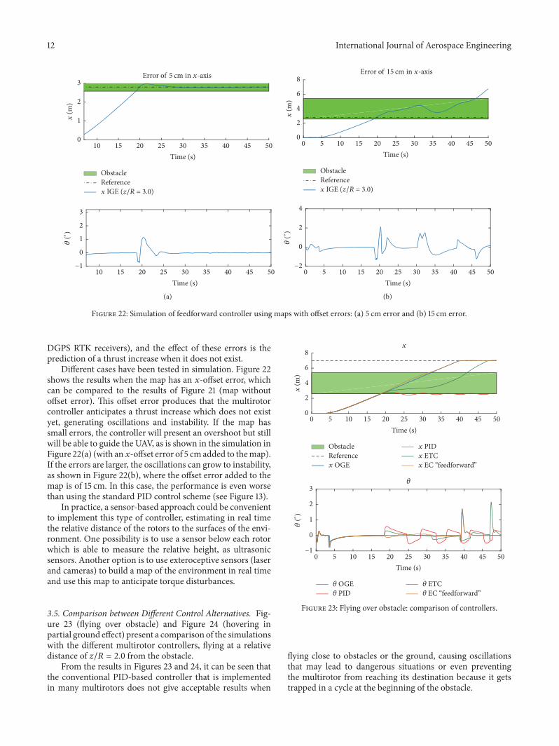
Different cases have been tested in simulation. Figure 22shows the results when the map has an 𝑥-offset error, whichcan be compared to the results of Figure 21 (map withoutoffset error). This offset error produces that the multirotorcontroller anticipates a thrust increase which does not existyet, generating oscillations and instability. If the map hassmall errors, the controller will present an overshoot but stillwill be able to guide the UAV, as is shown in the simulation inFigure 22(a) (with an𝑥-offset error of 5 cmadded to themap).If the errors are larger, the oscillations can grow to instability,as shown in Figure 22(b), where the offset error added to themap is of 15 cm. In this case, the performance is even worsethan using the standard PID control scheme (see Figure 13).
In practice, a sensor-based approach could be convenientto implement this type of controller, estimating in real timethe relative distance of the rotors to the surfaces of the envi-ronment. One possibility is to use a sensor below each rotorwhich is able to measure the relative height, as ultrasonicsensors. Another option is to use exteroceptive sensors (laserand cameras) to build a map of the environment in real timeand use this map to anticipate torque disturbances.
3.5. Comparison between Different Control Alternatives. Fig-ure 23 (flying over obstacle) and Figure 24 (hovering inpartial ground effect) present a comparison of the simulationswith the different multirotor controllers, flying at a relativedistance of 𝑧/𝑅 = 2.0 from the obstacle.
From the results in Figures 23 and 24, it can be seen thatthe conventional PID-based controller that is implementedin many multirotors does not give acceptable results when
ObstacleReferencex OGE
x PIDx ETCx EC “feedforward”
x
0
2
4
6
8
x (m
)
5 10 15 20 25 30 35 40 45 500Time (s)
EC “feedforward” OGE PID
ETC
5 10 15 20 25 30 35 40 45 500Time (s)
−1
0
1
2
3
(∘
)
Figure 23: Flying over obstacle: comparison of controllers.
flying close to obstacles or the ground, causing oscillationsthat may lead to dangerous situations or even preventingthe multirotor from reaching its destination because it getstrapped in a cycle at the beginning of the obstacle.

International Journal of Aerospace Engineering 13
ObstacleReferencex OGE
x PIDx ETCx EC “feedforward”
x
20 25 30 35 4015Time (s)
1.5
2
2.5
3
x (m
)
EC “feedforward” OGE PID
ETC
20 25 30 35 4015Time (s)
−1
0
1
2
3
(∘
)
Figure 24: Hovering in partial ground effect: comparison ofcontrollers.
With a detailed environment map, the feedforward con-troller will give better results, provided that the practicalimplementation issues are correctly addressed.
4. Experiments
Several experiments have beenmade to assess experimentallythe performance when themultirotor flies over an obstacle. Afirst set of experiments were done in a test bench in which themultirotor is allowed to rotate freely around one of the axes(pitch angle) (Figure 25(a)). The ground effect is introducedplacing a large plate under one of the rotors at differentdistances (Figure 25(b)), while the multirotor pitch angle iscontrolled by the cascaded PID controller.
Figure 26 shows the results of the experiment placing theground plate at 𝑧/𝑅 = 2 with both the PQUAD multirotorand the AMUSE aerial manipulator. The evolution of thepitch angle for both cases is presented in Figure 26 markingwith green background the case when the ground plate isplaced below one of the rotors. It can be seen that whenthe (partial) ground effect is present, the torque disturbanceinduces an increase in the pitch angle which is difficult tocorrect by the PID controller. Both experiments producedsimilar results; this is according to the experimental resultsobtained in Figure 3.
The next experiments were intended to demonstrate theviability of the control approaches presented in previoussections. A first test was performed implementing the feed-forward control scheme, in which the feedforward term wasactivated by a switch in the radio of the safety pilot. It can be
(a)
(b)
Figure 25: Experimental tests withmultirotors in the test bench: (a)the PQUAD and (b) the PQUAD with a ground plane.
seen in Figure 27 that when the feedforward controller wasnot activated (Figure 27(a)), the induced pitch perturbationis similar to the results in Figure 26. However, in Figure 27(b),the feedforward controller was tested using the switch in theradio and the controller could maintain the pitch angle stablywith much smaller variations.
A second test was performed, implementing the distur-bance observer presented in Section 3.2. Figure 28 shows thetime evolution of the pitch angle during the experiment. Asin previous experiments, the green background correspondsto the ground plate placed under one rotor. As can be seenin Figure 28, after placing the ground plate, the pitch anglebegins to increase, behaving similarly to the first experimentsin Figure 26, but right after that, the disturbance observer isable to estimate the external wrench and the controller caneffectively compensate it.
The last step in the experimental tests was to reproducehow the ground effect affects during a normal flight. Figure 29shows two images of the experiment: the first one in free flightand the second one when a ground plane is placed under oneof the rotors.
Figure 30 shows the evolution of the multirotor pitchangle and the reference during the experiment, in which themultirotor is being controlledwith the standardPID cascadedcontroller,markingwith green background the casewhenoneof the rotors is under the ground effect (partial ground effect).It can be seen that initially the response is similar to thetest bench experiments: the pitch angle suffers a perturbation

14 International Journal of Aerospace Engineering
Obstacler
6 842 10 120Time (s)
−1
0
1
2
3
4
5
(∘
)
(∘)(∘)
(a)
Obstacler
−2
−1
0
1
2
3
4
5
92 93 94 95 96 97 98 9991Time (s)
(∘)
(∘)(∘)
(b)
Figure 26: Experiments in the test bench: influence on the pitch angle of placing a ground plane under one of the rotors (green background).(a) Effect in the PQUADmultirotor. (b) Effect in the AMUSE multirotor.
Obstacler
82 84 86 88 9080Time (s)
−2
0
2
4
6
8
10
(∘
)
(∘)(∘)
(a)
Obstacler
92 94 96 98 10090Time (s)
−2
0
2
4
6
8
10
(∘
)
(∘)(∘)
(b)
Figure 27: Experiments in the test bench: variations of the quadrotor pitch angle when placing a ground plane under one of the rotors(green background): (a) with the standard PID controller (not compensating) and (b) when the compensation is implemented (feedforwardcontroller).
caused by the torque generated by the partial ground effect(different thrust forces of the same rotors for the same inputsignal). In this case, a perturbation appears in the oppositedirection when the partial ground effect disappears, whichwas present in some of the test bench experiments but withsmaller amplitude (see Figure 26(b) and Figure 27(a)). Thiscan be due to several factors of flying outdoors, for example,wind gusts or turbulences. It also can be explained becausethe quadrotor is attached to the test bench at two points inopposite arms of the quadrotor, allowing it to rotate around
the axis (see Figure 25), and the friction may dampen theoscillation.
5. Conclusions
This paper has shown the significance of the aerodynamicground effects on multirotor systems. The quantification ofthis effect is very relevant in applications involving flightvery close to surfaces as required in aerial manipulation.Thispaper has provided a precise characterization of the ground

International Journal of Aerospace Engineering 15
Obstacler
−4
−2
0
2
4
6
8
10
80 85 9075
(∘)(∘)
Figure 28: Experiments in the test bench: variations of the quadro-tor pitch angle when placing a ground plane under one of the rotors(green background).
(a)
(b)Figure 29: Partial ground effect tests with multirotor flying out-doors: (a)multirotor in free flight; (b)multirotor flying under partialground effect (the rotor at the right with a ground plane close to it).
Obstacler
−6−4−2
0246
256 258 260 262 264 266 268254Time (s)
(∘)
(∘)
Figure 30: Partial ground effect test with the multirotor in flight.
effect for multirotors in different situations, which has beenmodelled similar to single-rotor helicopters in many cases inthe literature. The ground effect has been shown to generatea stabilizing moment in multirotors due to the differences inheight over the ground of the different rotors. Moreover, theso-called partial ground effect, whenonly one rotor is over thesurface, has been studied.The paper has also shown by simu-lations and experiments which control strategies can be usedto compensate this effect. In future research, the dynamicground effect will be considered to complete these results.
Conflicts of Interest
The authors declare that they have no conflicts of interest.
Acknowledgments
This work has been supported by the AEROARMS project,funded by the European Commission under the H2020 Pro-gramme (H2020-2014-644271), the AEROMAIN (DPI2014-59383-C2-1-R) andAEROCROS (DPI2015-71524-R) projects,funded by the Spanish Ministerio de Economıa, Industriay Competitividad, and the FPU Programme, funded by theSpanish Ministerio de Educacion, Cultura y Deporte.
References
[1] K. P. Valavanis and G. J. Vachtsevanos,Handbook of UnmannedAerial Vehicles, Springer, 2015.
[2] M.Orsag, C. Korpela, andP.Oh, “Modeling and control ofMM-UAV:mobile manipulating unmanned aerial vehicle,” Journal ofIntelligent and Robotic Systems:Theory and Applications, vol. 69,no. 1-4, pp. 227–240, 2013.
[3] M. Fumagalli, R. Naldi, A. Macchelli et al., “Developing anaerial manipulator prototype: physical interaction with theenvironment,” IEEE Robotics and AutomationMagazine, vol. 21,no. 3, pp. 41–50, 2014.
[4] K. Kondak, A. Ollero, I. Maza et al., “Unmanned aerial sys-tems physically interacting with the environment: load trans-portation, deployment, and aerial manipulation,” Handbook ofUnmanned Aerial Vehicles, pp. 2755–2785, 2015.

16 International Journal of Aerospace Engineering
[5] S. Kim, H. Seo, and H. J. Kim, “Operating an unknown drawerusing an aerial manipulator,” in Proceedings of the 2015 IEEEInternational Conference on Robotics and Automation, ICRA2015, pp. 5503–5508, May 2015.
[6] G. Heredia, A. E. Jimenez-Cano, I. Sanchez et al., “Control ofa multirotor outdoor aerial manipulator,” in Proceedings of the2014 IEEE/RSJ International Conference on Intelligent Robotsand Systems, IROS 2014, pp. 3417–3422, September 2014.
[7] A. E. Jimenez-Cano, J. Braga, G. Heredia, and A. Ollero,“Aerial manipulator for structure inspection by contact fromthe underside,” in Proceedings of the IEEE/RSJ InternationalConference on Intelligent Robots and Systems, IROS 2015, pp.1879–1884, October 2015.
[8] H. Tsukagoshi, M. Watanabe, T. Hamada, D. Ashlih, and R.Iizuka, “Aerial manipulator with perching and door-openingcapability,” in Proceedings of the 2015 IEEE International Confer-ence on Robotics and Automation, ICRA 2015, pp. 4663–4668,May 2015.
[9] AEROARMS Project website, “Aerial Robotics CooperativeAssembly system,” http://www.arcas-project.eu.
[10] ARCAS Project website, http://www.aeroarms-project.eu.[11] I. Cheeseman and W. Bennett, “The effect of the ground on a
helicopter rotor in forward flight,” ARC R&M 3021, 1955.[12] E. A. Fradenburgh, “The helicopter and the ground effect
machine,” Journal of the American Helicopter Society, vol. 5, no.4, pp. 24–33, 1960.
[13] H. C. Curtiss Jr., M. Sun, W. F. Putman, and E. J. Hanker Jr.,“Rotor aerodynamics in ground effect at low advance ratios,”Journal of the American Helicopter Society, vol. 29, no. 1, pp. 48–55, 1984.
[14] T. E. Lee, J. G. Leishman, andM. Ramasamy, “Fluid dynamics ofinteracting blade tip vortices with a ground plane,” Journal of theAmerican Helicopter Society, vol. 55, no. 2, pp. 22005–2200516,2010.
[15] P. Tanner, A. Overmeyer, L. Jenkins, C. S. Yao, and S. Bartram,“Experimental investigation of rotorcraft outwash in groundeffect,” in Proceedings of the 71th Annual Forum of the AmericanHelicopter Society, pp. 1–26, 2015.
[16] J. S. Hayden, “Effect of the ground on helicopter hovering powerrequired,” in Proceedings of the AHS 32nd Forum, 1976.
[17] K. Nonaka and H. Sugizaki, “Integral sliding mode altitudecontrol for a smallmodel helicopterwith ground effect compen-sation,” in Proceedings of the 2011 American Control Conference,pp. 202–207, San Francisco, CA, June 2011.
[18] M. Bangura and R. Mahony, “Nonlinear dynamic modelingfor high performance control of a quadrotor,” in Proceedingsof the Australasian Conference on Robotics and Automation,Wellington, New Zealand, 2012.
[19] D. Abeywardena, Z. Wang, G. Dissanayake, S. L. Waslander,and S. Kodagoda, “Model-aided state estimation for quadrotormicro air vehicles amidst wind disturbances,” in Proceedings ofthe 2014 IEEE/RSJ International Conference on Intelligent Robotsand Systems, IROS 2014, pp. 4813–4818, September 2014.
[20] M. Bangura, H. Lim, H. J. Kim, and R. Mahony, “Aerodynamicpower control for multirotor aerial vehicles,” in Proceedingsof the 2014 IEEE International Conference on Robotics andAutomation, ICRA 2014, pp. 529–536, June 2014.
[21] C. D. McKinnon and A. P. Schoellig, “Unscented external forceand torque estimation for quadrotors,” in Proceedings of the2016 IEEE/RSJ International Conference on Intelligent Robotsand Systems, IROS 2016, pp. 5651–5657, October 2016.
[22] T. Tomic and S. Haddadin, “A unified framework for externalwrench estimation, interaction control and collision reflexes forflying robots,” in Proceedings of the 2014 IEEE/RSJ InternationalConference on Intelligent Robots and Systems, IROS 2014, pp.4197–4204, September 2014.
[23] F. Ruggiero, J. Cacace, H. Sadeghian, and V. Lippiello,“Impedance control of VToL UAVs with a momentum-basedexternal generalized forces estimator,” in Proceedings of the 2014IEEE International Conference on Robotics and Automation,ICRA 2014, pp. 2093–2099, June 2014.
[24] B. Yuksel, C. Secchi,H.H. Bulthoff, andA. Franchi, “Anonlinearforce observer for quadrotors and application to physicalinteractive tasks,” in Proceedings of the 2014 IEEE/ASME Inter-national Conference on Advanced Intelligent Mechatronics, AIM2014, pp. 433–440, July 2014.
[25] T. Tomic and S. Haddadin, “Simultaneous estimation of aero-dynamic and contact forces in flying robots: Applications tometric wind estimation and collision detection,” in Proceedingsof the 2015 IEEE International Conference on Robotics andAutomation, ICRA 2015, pp. 5290–5296, Seattle, USA,May 2015.
[26] N. Guenard, T. Hamel, and L. Eck, “Control laws for the teleoperation of an unmanned aerial vehicle known as an X4-flyer,”in Proceedings of the Proceeding of the IEEE/RSJ InternationalConference on Intelligent Robots and Systems (IROS ’06), pp.3249–3254, Beijing, China, October 2006.
[27] H. Nobahari and A. R. Sharifi, “Continuous ant colony filterapplied to online estimation and compensation of ground effectin automatic landing of quadrotor,” Engineering Applications ofArtificial Intelligence, vol. 32, pp. 100–111, 2014.
[28] L. Danjun, Z. Yan, S. Zongying, and L. Geng, “Autonomouslanding of quadrotor based on ground effect modelling,” inProceedings of the 34th Chinese Control Conference, CCC 2015,pp. 5647–5652, July 2015.
[29] J. Bartholomew, A. Calway, and W. Mayol-Cuevas, “Learningto predict obstacle aerodynamics from depth images for microair vehicles,” in Proceedings of the 2014 IEEE InternationalConference on Robotics and Automation, ICRA 2014, pp. 4967–4973, June 2014.
[30] C. Hooi, F. Lagor, and D. Paley, “Flow sensing for heightestimation and control of a rotor in ground effect: modelingand experimental results,” in Proceedings of the AHS 71st AnnualForum, Virginia Beach, USA, May 2015.
[31] C. Powers, D. Mellinger, A. Kushleyev, B. Kothmann, and V.Kumar, “Influence of aerodynamics and proximity effects inquadrotor flight,” in Experimental Robotics, vol. 88 of SpringerTracts in Advanced Robotics, pp. 289–302, Springer Interna-tional Publishing, Heidelberg, 2013.
[32] I. Sharf, M. Nahon, A. Harmat et al., “Ground effect experi-ments and model validation with Draganflyer X8 rotorcraft,” inProceedings of the 2014 International Conference on UnmannedAircraft Systems, ICUAS 2014, pp. 1158–1166, May 2014.
[33] D. A. Griffiths, S. Ananthan, and J. G. Leishman, “Predictionsof rotor performance in ground effect using a free-vortex wakemodel,” Journal of the American Helicopter Society, vol. 50, no.4, pp. 302–314, 2005.
[34] P. Castillo, R. Lozano, and A. Dzul, Modelling and Control ofMini-Flying Machines, Springer, 2005.
[35] R. Mahony, V. Kumar, and P. Corke, “Multirotor aerial vehicles:modeling, estimation, and control of quadrotor,” IEEE Roboticsand Automation Magazine, vol. 19, no. 3, pp. 20–32, 2012.
[36] J. W. Seo, B. E. Lee, B. S. Kang, S. J. Oh, and K. J. Yee, “Exper-imental study on the small-scale rotor hover performance in

International Journal of Aerospace Engineering 17
partial ground conditions,” Journal of the Korean Society forAeronautical & Space Sciences, vol. 38, no. 1, pp. 12–21, 2010.
[37] H. Lim, J. Park, D. Lee, and H. J. Kim, “Build your ownquadrotor: Open-source projects on unmanned aerial vehicles,”IEEE Robotics and Automation Magazine, vol. 19, no. 3, pp. 33–45, 2012.
[38] S. Bellens, J. De Schutter, and H. Bruyninckx, “A hybridpose/ wrench control framework for quadrotor helicopters,” inProceedings of the IEEE International Conference onRobotics andAutomation (ICRA), 2012.

RoboticsJournal of
Hindawi Publishing Corporationhttp://www.hindawi.com Volume 2014
Hindawi Publishing Corporationhttp://www.hindawi.com Volume 2014
Active and Passive Electronic Components
Control Scienceand Engineering
Journal of
Hindawi Publishing Corporationhttp://www.hindawi.com Volume 2014
International Journal of
RotatingMachinery
Hindawi Publishing Corporationhttp://www.hindawi.com Volume 2014
Hindawi Publishing Corporation http://www.hindawi.com
Journal of
Volume 201
Submit your manuscripts athttps://www.hindawi.com
VLSI Design
Hindawi Publishing Corporationhttp://www.hindawi.com Volume 201
Hindawi Publishing Corporationhttp://www.hindawi.com Volume 2014
Shock and Vibration
Hindawi Publishing Corporationhttp://www.hindawi.com Volume 2014
Civil EngineeringAdvances in
Acoustics and VibrationAdvances in
Hindawi Publishing Corporationhttp://www.hindawi.com Volume 2014
Hindawi Publishing Corporationhttp://www.hindawi.com Volume 2014
Electrical and Computer Engineering
Journal of
Advances inOptoElectronics
Hindawi Publishing Corporation http://www.hindawi.com
Volume 2014
The Scientific World JournalHindawi Publishing Corporation http://www.hindawi.com Volume 2014
SensorsJournal of
Hindawi Publishing Corporationhttp://www.hindawi.com Volume 2014
Modelling & Simulation in EngineeringHindawi Publishing Corporation http://www.hindawi.com Volume 2014
Hindawi Publishing Corporationhttp://www.hindawi.com Volume 2014
Chemical EngineeringInternational Journal of Antennas and
Propagation
International Journal of
Hindawi Publishing Corporationhttp://www.hindawi.com Volume 2014
Hindawi Publishing Corporationhttp://www.hindawi.com Volume 2014
Navigation and Observation
International Journal of
Hindawi Publishing Corporationhttp://www.hindawi.com Volume 2014
DistributedSensor Networks
International Journal of