Embed Size (px)
Citation preview
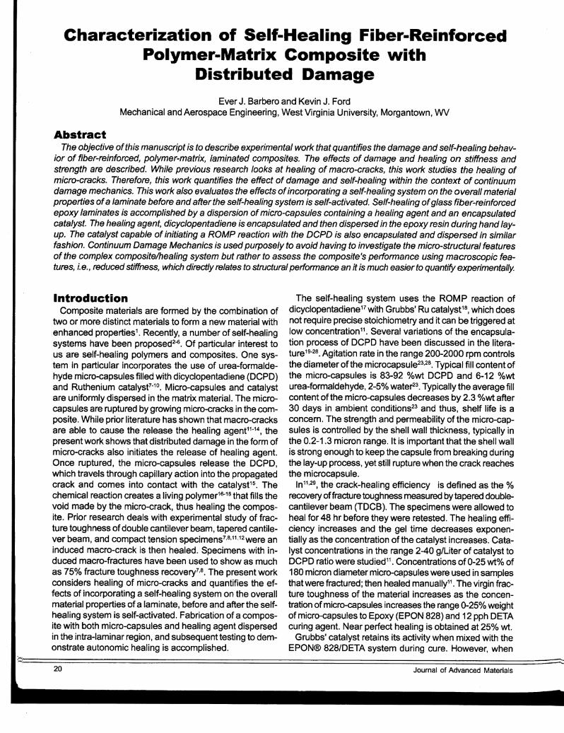
Characterization of Self-Healing Fiber-ReinforcedPolymer-Matrix Composite with
Distributed Damage
Ever J. Barbero and Kevin J. FordMechanical and Aerospace Engineering, West Virginia University, Morgantown, WV
AbstractTh.e objective ofthis manuscript is to describe experimental work that quantifies the damage and self-healing behav
ior of fiber-reinforced, polymer-matrix, laminated composites. The effects of damage and healing on stiffness andstrength are described. While previous research looks at healing of macro-cracks, this work studies the healing ofmicro-cracks. Therefore, this work quantifies the effect of damage and self-healing within the context of continuumdamage mechanics. This work also evaluates the effects of incorporating a self-healing system on the overall materialproperties ofa laminate before and after the self-healing system is self-activated. Self-healing ofglass fiber-reinforcedepoxy laminates is accomplished by a dispersion ofmicro-capsules containing a healing agent and an encapsulatedcatalyst. The healing agent, dicyclopentadiene is encapsulated and then dispersed in the epoxy resin during hand layup. The catalyst capable of initiating a ROMP reaction with the DCPD is also encapsulated and dispersed in similarfashion. Continuum Damage Mechanics is used purposely to avoid having to investigate the micro-structural featuresof the complex composite/healing system but rather to assess the composite's performance using macroscopic features, i.e., reduced stiffness, which directly relates to structural performance an it is much easier to quantify experimentally.
IntroductionComposite materials are formed by the combination of
two or more distinct materials to form a new material withenhanced properties1. Recently, a number of self-healingsystems have been proposed2-6. Of particular interest tous are self-healing polymers and composites. One system in particular incorporates the use of urea-formaldehyde micro-capsules filled with dicyclopentadiene (DCPD)and Ruthenium catalyst7-
10. Micro-capsules and catalystare uniformly dispersed in the matrix material. The microcapsules are ruptured by growing micro-cracks in the composite. While prior literature has shown that macro-cracksare able to cause the release the healing agent11-14, thepresent work shows that distributed damage in the form ofmicro-cracks also initiates the release of healing agent..Once ruptured, the micro-capsules release the DepO,which travels through capillary action into the propagatedcrack and comes into contact with the catalyst15. Thechemical reaction creates a living polymer16-18 that fiUs thevoid made by the micro-crack, thus healing the composite. Prior research deals with experimental study of fracture toughness of double cantilever beam, tapered cantilever beam, and compact tension specimens7,8,11,12 were aninduced macro-crack is then healed. Specimens with induced macro-fractures have been used to show as muchas 75°k fracture toughness recovery7,8. The present workconsiders healing of micro-cracks and quantifies the effects of incorporating a self-heating system on the overallmaterial properties of a laminate, before and after the selfhealing system is self-activated. Fabrication of a composite with both micro-capsules and healing agent dispersedin the intra-laminar region, and subsequent testing to demonstrate autonomic healing is accomplished.
The self-healing system uses the ROMP reaction ofdicyclopentadiene17 with Grubbs' Ru catalyst18, which doesnot require precise stoichiometry and it can be triggered atlow concentration11
• Several variations of the encapsulation process of DCPD have been discussed in the literature19
-28• Agitation rate in the range 200-2000 rpm controlsthe diameter of the microcapsule23,28. Typical fill content ofthe micro-capsules is 83-92 %wt DCPD and 6-12 °kwturea-formaldehyde, 2-5% water23 • Typically the average fillcontent of the micro-capsules decreases by 2.3 °A,wt after30 days in ambient conditions23 and thus, shelf life is aconcern. The strength and permeability of the micro-capsules is controlled by the shell wall thickness, typically inthe 0.2-1.3 micron range. It is important that the shell wallis strong enough to keep the capsule from breaking duringthe lay-up process, yet still rupture when the crack reachesthe microcapsule.
In11 ,29, the crack-healing efficiency is defined as the %recovery offracture toughness measured by tapered doublecantilever beam (TOCS). The specimens were allowed toheal for 48 hr before they were retested. The healing efficiency increases and the gel time decreases exponentially as the concentration of the catalyst increases. Catalyst concentrations in the range 2-40 g/Liter of catalyst toDCPD ratio were studied 11 • Concentrations of 0-25 wt% of180 micron diameter micro-capsules were used in samplesthat were fractured; then healed manually11. The virgin fracture toughness of the material increases as the concentration ofmicro-capsules increases the range 0-25°k weightof micro-capsules to Epoxy (EPON 828) and 12 pph DETAcuring agent. Near perfect healing is obtained at 25% wt.
Grubbs· catalyst retains its activity when mixed with theEPON® 828/DETA system during cure. However, when
~~;====================================================================================:=::::-20 Journal of Advanced Materials
mixed with the DETA curing agent alone the catalyst experiences rapid deactivation11 • Catalyst particle sizes inthe range 180-355 microns produce the highest healingefficiency out of a range 75-1000 micron studied11
• Thevirgin fracture toughness decreases and the healing efficiency increases as the concentration of the catalyst increases from 0-4 %wt of resin 11. This is due to the toughening effect of the foreign particles in the neat Epoxy. Maximum toughness reported in the literature may reach 1270t'<> of the neat epoxy toughness. Smaller micro-capsulesyield more toughening even at lowerconcentrations30
•
Larger micro-capsules yield greater efficiency.. While using 2.5 %wt catalyst and 10 %wt micro-capsules with sizesin the 180-460 micron range, the 460 micron micro-capsules yield the greatest healing efficiency11. The time forthe reaction of Grubbs' catalyst and the DCPD healingagent also plays an important role in the healing efficiencyof the specimen. Using 5-10 %wt of 180 microns diametermicro-capsules and 2.5 wt% catalyst, significant healingefficiencies develop after 25 min and steady-state valuesare reached after 10 hr11
•
Delamination healing between layers ofwoven composites is reported in12 , where the catalyzed healing agentwas manually injected into the delamination region. Alternatively, un-catalyzed healing agent was injected into thedelamination region of specimens that had only catalystembedded.
The rate of in-situ polymerization for self-activated materials must be fast to prevent diffusion of the monomer intothe matrix16• Since the healing system is a living polymerization, repeated healing can occur16• The healing efficiencyincreases with the time the specimen is allowed to healuntil a maximum efficiency is reached at 48 Hr15.
Since the catalyst does not disperse well in the epoxymatrix and Diethylenetriamine (DETA) severely degradesthe catalyst as the epoxy initially cures, the catalyst wasencapsulated in paraffin wax31 . DeB fracture toughnessafter healing with encapsulated catalyst loading in the range0-1.25 °/owt increases with catalyst loading up to 0.75 °kwt,reaching a healing efficiency of 93°/031 •
Other healing processes such as geological rock densification32
, self-healing healing of concrete33,34, and self-heal
ing healing of ceramic materials35,36 have been discussedin the literature. Some models for bone remodeling orwounded skin regeneration have been developed for relatively simple cases37-39• A constitutive model for compaction of crushed rock salt has been proposed in the thermodynamic framework32
•
Barbero et al.40 developed a Continuous Damage andHealing Mechanics (CDHM) model to predict the effects ofdamage and subsequent self-healing as a function of loadhistory. The damage portion of the model has been extensively identified and verified with data available in the literature41 •46• The self-healing portion of the models could notbe identified nor verified until now because lack of experimental data for laminates undergoing distributed damage(e.g., micro-cracking). Prior data exists only for fracturetoughness recovery due to healing of macro-cracks. There-
Volume 39, No.4, October 2007
fore, the objective of this manuscript is to describe experimental work that quantifies the damage and self-healingbehavior of fiber-reinforced, pOlymer-matrix, laminated composites subjected to micro-crack damage. The effects ofdamage, healing, damage hardening, and hardening recovery upon healing, are described. This work also evaluates the effects of incorporating a self-healing system onthe overall material properties of a laminate before and after the self-healing system is self-activated.
Materials and MethodsEthylene maleic anhydride (EMA) copolymer was ob
tained from Zeeland Chemicals. Dicyclopentadiene (DCPD),urea, ammonium chloride, formaldehyde, and sodium hydroxide were purchased from Fisher Scientific. Resorcinol, hydrochloric acid, and 1-octanol were purchased fromJ.T. Baker. K-type thermocouples and thermocouple readerwere purchased from OMEGA. A Eurostar power controlvisc digital mixer was purchased from IKA Works, INC. Athree-bladed, 63.5mm diameter low-shear mixing impellerwas purchased from Cole Parmer. All solvents and substance used for preparation of EMA solution, acid and basesolutions and 1-octanol were of analytical grade.Bis(tricyclohexylphosphine)benzylidine ruthenium (IV)dichloride (Grubbs' Ru catalyst) was purchased from Materia. A Gilson Performer III sieve shaker and sieves werepurchased from Gilson Company, Inc. Neutral activatedaluminum oxide and paraffin wax was purchased fromSigma Aldrich.
Samples were fabricated by hand lay-up and vacuumbagging of fiberglass/Epoxy with 52°/0 fiber volume fractionfor all systems. The addition of micro-capsules reducesthe matrix volume fraction only. The reinforcement contains 90°/0 of the fibers in the longitudinal direction and10% in the transverse direction in a non-woven, non-stitchedsystem, which is held together by a binding agent whendry. Various laminate stacking sequences (LSS) were fabricated including unidirectional [O]T' cross-ply [O)90s ' and[(0/90)]nI45/-45]s' where n is the number of (0/90) groups,including quasi-isotropic [0/90/45/-45]5' Unidirectional [O]Twere used to identify the model parameters (Tables 1 and2). All other laminate stacking sequences (LSS) were usedto verify the model prediction. The model is reported in40
•47
•
Samples were fabricated with and without the self healing system. Those with self heating contained encapsulated DCPD at 200/0wt of Epoxy and wax-encapsulatedcatalyst at 1.5 °,lc,wt of Epoxy. Vacuum bagging techniqueis used to consolidate the samples, which are cured atroom temperature for 24 Hr. Tensile ASTM D303948
, compressive SACMA-SRM-1 R-9449 , and shearASTM 0537950
specimens were cut from these samples.In order to observe the damage effects uncoupled from
the healing effects, three types of tests were conducted.Damage tests of unidirectional samples having no selfhealing were conducted to obtain baseline properties. Damage tests of unidirectional samples with self-healing system were conducted within a short period of time (two minutes or less at a loading rate of 0.05 in/min) without atlow-
21
[2]
[1 ]
-6
-52
-35
-12
-33
...34
-1.5
9.51
4.95
8.45
4.36
6.79
6.28
14.45
12.61
12.61
13.32
Coefficient
%reduction
w.r.t Table 1
of Variation (%)
Upon unloading, the subsequent loading modulus is equalto the last unloading modulus provided there is no healing.The modulus can be partially or totally recovered if thematerials is allowed to heal. The amount of healing is represented by h and the damage is reduced, or healed, to a
in terms of the unloading modulus Gl~ and the initial (undamaged) modulus 012 as
8.2
9.5
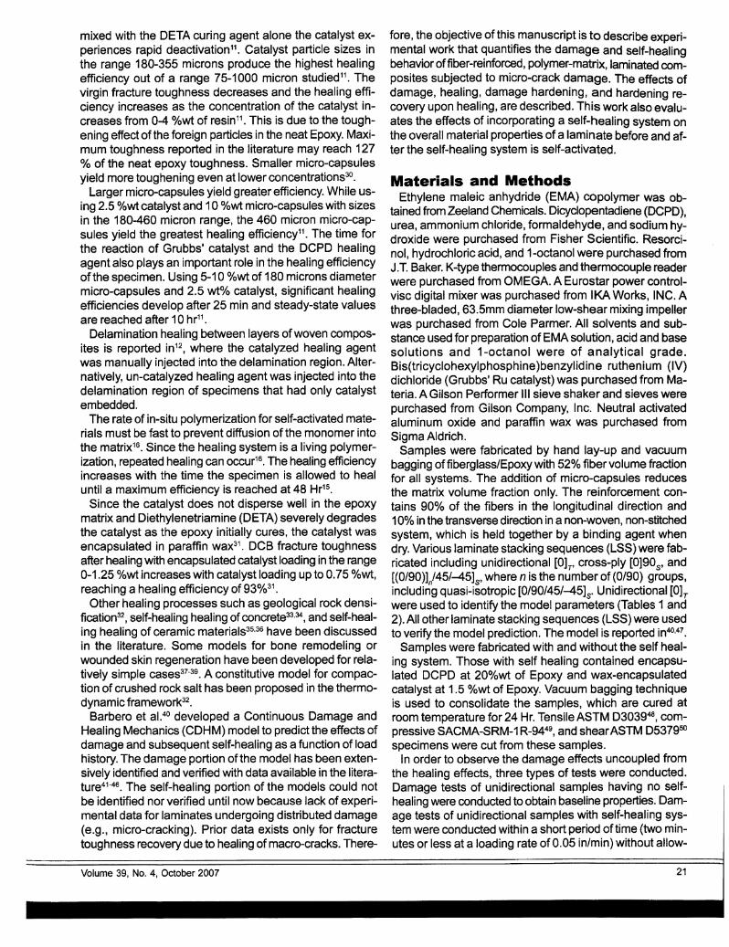
Unrecoverable (plastic) strain can beobserved upon unloading, but only after a threshold value of stress (Le.,the yield strength) or strain (Le., theyield strain) is reached during loading(Figure 3).
Even though plastic strain is accumulated, initially the unloading modulus remain unchanged and equal tothe loading modulus. For the unloading modulus to change, that is to decrease below the value of the initialloading modulus, damage must appear. Note that the word "unloading"is added for emphasis and becausethe reduction in modulus is first detected during unloading of the specimen. But off course the modulus reduction is permanent. A reduction ofthe unloading modulus with respectto the initial loading modulus can beobserved only after a threshold valueof stress (i.e., the damage thresholdstress) or strain (Le., the damagethreshold strain) is reached duringloading (Figure 4).
The threshold stress F6EP for appearance of unrecoverable (plastic) strain(Le., the yield strength), and thethreshold stress F6ED for appearanceof irreversible damage, are read fromthe loading portion of the 06(Y6) curve(Figure 1) with the aid of Figures 3and4.
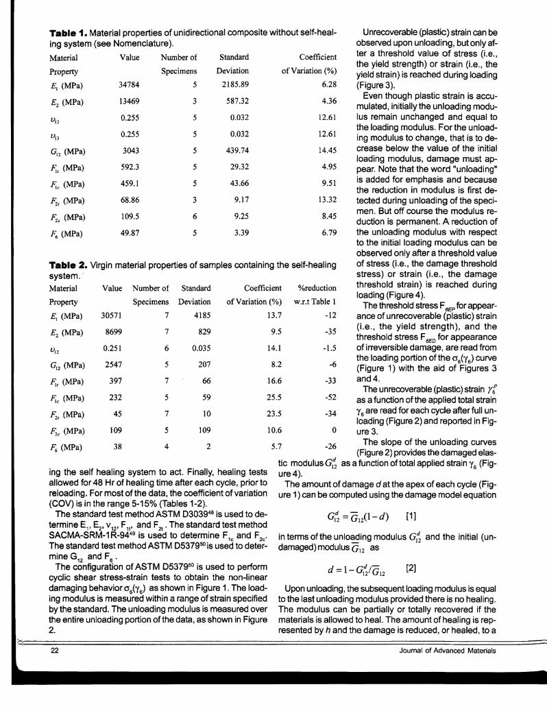
The unrecoverable (plastic) strain rtas a function of the applied total strain'Y6 are read for each cycle after full unloading (Figure 2) and reported in Fig-
10.6 0 ure 3.
5 7 -26 The slope of the unloading curves. (Figure 2) provides the damaged elas-tic modulus Gt; as a function of total applied strain Y6 (Figure 4).
The amount of damage d at the apex of each cycle (Figure 1) can be computed using the damage model equation
16.6
14.1
23.5
25.5
Coefficient
of Variation (0/0)
13.7
Standard
StandardNumber ofValue
Property Specimens Deviation
£1 (MPa) 34784 5 2185.89
£2 (MPa) 13469 3 587.32
u120.255 5 0.032
un 0.255 5 0.032
G12 (MPa) 3043 5 439.74
~l (MPa) 592.3 5 29.32
F;c (MPa) 459.1 5 43.66
F;t (MPa) 68.86 3 9.17
F;c (MPa) 109.5 6 9.25
~ (MPa) 49.87 5 3.39
Table 1. Material properties of unidirectional composite without self-healing system (see Nomenclature).
Material Value Number of
Property Specimens Deviation
E] (MPa) 30571 7 4185
£2 (MPa) 8699 7 829
V12 0.251 6 0.035
GI2 (MPa) 2547 5 207
~f (MPa) 397 7 66
F.c (MPa) 232 5 59
F;t (MPa) 45 7 10
F;c (MPa) 109 5 109
~ (MPa) 38 4 2
Table 2. Virgin material properties of samples containing the self-healingsystem..
Material
ing the self healing system to act. Finally, healing testsallowed for 48 Hr of healing time after each cycle, prior toreloading. For most of the data, the coefficient of variation(COV) is in the range 5-150/0 (Tables 1-2).
The standard test method ASTM 0303948 is used to determine E1J E2, V12 , F
1t, and F
2t• The standard test method
SACMA-SRM-1 R-9449 is used to determine F1c and F2e'
The standard test method ASTM 0537950 is used to determine G12 and F6 •
The configuration of ASTM D537950 is used to performcyclic shear stress-strain tests to obtain the non-lineardamaging behavior°6("(6) as shown in Figure 1. The loading modulus is measured within a range of strain specifiedby the standard. The unloading modulus is measured overthe entire unloading portion of the data, as shown in Figure2.
~~;;.=.===============================================================================================22 Journal of Advanced Materials
--Experimental data
-D-Loading G12=4.02 GPa
~.t}.~.~~~~.i~.~ G12=4.0S GPa
ASTM strain range
0.1 0.2 0.3 0.4 0.5 0.6 0.7 0.8 0.9
Shear Strain [%}
Figure 2. Determination of loading and unloading shearmodulus of unidirectional sample as per ASTM 05379.
60 30
50 25
l40 '(ij' 20no~ ~0 (I>0~ 30
(I)
~ 15en Ci5(ij<D Co§.i 20
Q)
~ 10 .
10·5
0-
0 2 3 4 5 6 70
0Shear strain [%]
Figure 1. Shear stress-strain behavior of unidirectional,neat specimen (no self-healing system). Loss of stiffnessand accumulation of plastic strain are evident.
newvalue6 ....----------------------r
The loading modulus is then
Gl~ = GI2(1- dh ) [4]
A definition for the efficiency lld of the healing system isproposed as
32.521.50.5
5
..... 4~c:.~
as3<.>
~a::: 2
[3]
[5]
where at and r~dare adjusted to fit the experimental dataas shown in Figure 4, with r~dbeing the damage thresholdstrain.
where ai, af, r~P are adjusted to fit the experi
mental data as shown in Figure 3, with r~P being theyield strain.
The reduction of shear modulus is modeled with the linear relationship
32.5
o Unloading ,: -Unloading trend :~ • Cycle 1 Loading :'.~ .f\I.~.~~~g~ . ...
Maximum Applied Strain [%]
5
4.5 .
«ra.. 4f2.f/J::s:g 3.50~
toG) 3 ...c.C/)
2.5
2
0 0.5
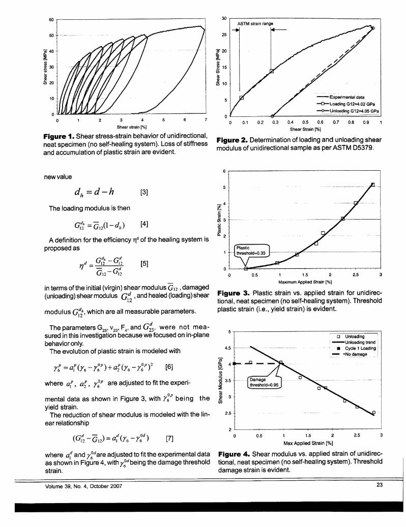
Figure 3. Plastic strain vs. applied strain for unidirectional, neat specimen (no self-healing system). Thresholdplastic strain (Le., yield strain) is evident.
1 1.5 2
Max Applied Strain [0/01
Figure 4. Shear modulus vs. applied strain of unidirectional, neat specimen (no self-healing system). Thresholddamage strain is evident.
[7]
in terms of the initial (virgin) shear modulus G12 ,damaged(unloading) shear modulus Gd ,and healed (loading) shear
12
modulus G~, which are all measurable parameters.
The parameters G23 , V23, F4 , and G;3 1 were not measured in this investigation because we focused on in-planebehavior only.
The evolution of plastic strain is modeled with
Volume 39, No.4, October 2007 23

90- 140
80· F2c =110MPaF2t=69 MPa (;i'120 --_.~..._.•._•....._-_. -_....... _.....~ .._... - ...
a.as 70 ------- ~CL
~en 100C/)
(I) 60 ~(I) w~ Q)
CiS 50· .~ 80Q) (J)
:as mc:
40 a.s E 60 _.Q) 0~
(.)
(1) 30 <D
in E2 = 13470 MPa ~ 40Q)c: .>~ 20 (I).... c:
as~ 20
10
0 0
0.00 0.25 0.50 0.75 1.00 1.25 0 2 4 6 8 10 12
Transverse tensile strain [%]
Figure 5. Transverse tensile stress-strain behavior of threeunidirectional, neat specimens (no self-healing system).Loss of stiffness is evident.
Effect on Initial PropertiesThe self healing system occupies space that otherwise
could be occupied by neat resin, which results in reduction of longitudinal, transverse, and shear stiffness. Material properties are reported in Table 1 for the unidirectionalcomposite without self-healing system and in Table 2 forthe composite with the self-healing system but not allowedto heal. Addition of micro-capsules results in a reductionof the longitudinal compressive strength but not of transverse compression strength. Furthermore. longitudinal tensile, transverse tensile, and shear strength are reduceddue to the presence of the micro-capsules. On the otherhand, dispersion of micro-capsules has a beneficial effecton fracture toughness, as reported in30
•
It can be seen in Table 2 that most properties are significantly degraded by the inclusion of the self-healing system. It must be noted that in this study the °A,wt of microcapsules and encapsulated catalyst were purposely setto high values in order to obtain noticeable and significanteffects of healing on the observed behavior. It remains for asubsequent study to optimize the tradeoff between knockdown of initial properties and self-healing recovery.
Damage EffectsIt is important to note that continuum damage mechan
ics (CDM), and by extension continuum damage-healingmechanics (CDHM40), does not attempt to identify the precise damage mechanisms that take place. Instead, damage is just a state variable that represents the loss of stiffness due to damage51
• In this manuscript, healing is simply damage recovery, which is equivalent to stiffness recove,y°.
Loss of stiffness due to damage is evident in all tensileand shear tests of unidirectional samples with or withoutembedded self healing, but it is more evident for transverse tensile (Figure 5) and shear loading (Figure 4). Theloss of stiffness during transverse tensile tests is shown inFigure 5 for the sample without self-healing system. Simi-
Transverse compressive strain [%]
Figure 6. Transverse compression stress-strain behavior of four unidirectional samples with self-healing system.Note the early loss of stiffness.
lar behavior is observed in the samples with self-healingsystem.
Transverse compression tests of unidirectional sampleswith self healing system show noticeable but not severeloss of stiffness at about one-third of the transverse compression strength (Figure 6).
Existence of damage and a damage threshold are demonstrated by the fact that measured unloading modulus isless than the loading modulus after the damage thresholdhas been reached (Figure 4). No loss of stiffness occurswhen the applied strain is less than the threshold. Afterthe threshold is reached, the loss of modulus is proportional to the applied strain. Since careful visual inspectionafter each loading cycle does not reveal appearance ofany macro-crack, the loss of modulus is attributed andmodeled as distributed damage.
Also noticeable in Figure 3 is the accumulation of unrecoverable (plastic) strain. While the physical, microstructural, and morphological mechanisms leading to plasticityin polymers are different than those leading to plasticity inmetals, from a phenomenological and modeling point ofview, unrecoverable deformations can be modeled with plasticity theory as long as the plastic strains are not associated to a reduction of the unloading modulus. The reduction of unloading modulus, which occurs independently ofthe plastic strain, can be accounted for by continuum damage mechanics. Each of these two phenomena have different thresholds for initiation and evolve with different rates.They are, however, coupled by the redistribution of stressthat both phenomena induce. In the model this is takeninto account by formulating the plasticity model in termsof effective stress computed by the damage model40.
Shear tests reveal marked non-linearity (Figure 1) reaching almost total loss of tangent stiffness prior to failure,which occurs at large values of shear strain. Unloadingsecant stiffness reveals marked loss of stiffness due todamage, which worsens during cyclic re-Ioading (Figure4). Also, unloading reveals significant plastic strains, ac-
24~~:,====================================================================================================::::::Journal of Advanced Materials
cumulating during cyclic re-Ioading (Figure 3). These effects are observed for both types of samples J with andwithout embedded self healing.
The unidirectional material without healing system has aplastic threshold r~P=0.330/0, which is lower than the dam-
age threshold r~d =0.950/0 . At first, the material accumu-
lates plastic strain without noticeable loss of unloadingmodulus. A typical loading-unloading cycle is depicted inFigure 2.
Healing EffectsWhen the material is allowed to heal for 48 Hr after each
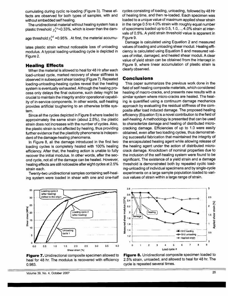
load-unload cycle, marked recovery of shear stiffness isobserved in subsequent shear loading (Figure 7). Repeatedloading-unloading-healing cycles reveal that the healingsystem is eventually exhausted. Although the healing process only delays the final outcome, such delay might becrucial to maintain the integrity and/or operational capability of in-service components. In other words, self-healingprovides artificial toughening to an otherwise brittle system.
Since all the cycles depicted in Figure 8 where loaded toapproximately the same strain (about 2.5%), the plasticstrain does not increases with the number of cycles. Also,the plastic strain is not affected by healing, thus providingfurther evidence that the plasticity phenomena is independent of the damage-healing phenomena.
In Figure 8, all the damage introduced in the first twoloading cycles is completely healed with 1000/0 healingefficiency. After that, the healing action is unable to fullyrecover the initial modulus. In other words, after the second cycle, not all of the damage can be healed. However,healing effects are still noticeable after eight cycles at 2.5°kstrain each.
Twenty-two unidirectional samples containing self-healing system were loaded in shear with one and one-half
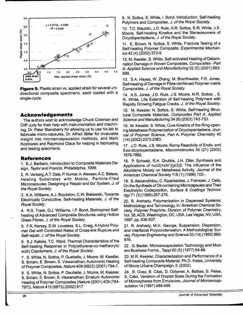
cycles consisting of loading, unloading, followed by 48 Hrof healing time, and then re-Ioaded. Each specimen wasloaded to a unique value of maximum applied shear strainin the range 0.5 to 4.0% strain with roughly equal numberof specimens loaded up to 0.5, 1.0, .. , 4.0ok strain at intervals of O.5ok. A yield strain threshold value is apparent inFigure 9.
Damage is calculated using Equation 2 and measuredvalues of loading and unloading shear moduli. Healing efficiency is calculated using Equation 5 and measured values of initial, damaged, and healed shear moduli. A clearvalue of yield strain can be obtained from the intercept inFigure 9, where linear accumulation of plastic strain isclearly observed.
ConclusionsThis paper summarizes the previous work done in the
field ofself-healing composite materials, which consideredhealing of macro-cracks, and presents new results with asimilar system where micro-cracks are healed. The healing is quantified using a continuum damage mechanicsapproach by evaluating the residual stiffness of the composite after load induced damage. The proposed healingefficiency (Equation 5) is a novel contribution to the field ofself-healing. A methodology is presented that can be usedto characterize damage and healing of distributed microcracking damage. Efficiencies of up to 1.0 were easilyobtained, even after two loading cycles, thus demonstrating successful fabrication that maintained the integrity ofthe encapsulated healing agent while allowing release ofthe healing agent under the action of distributed microcrack damage. Knockdown of nominal properties due tothe inclusion of the self-healing system were found to besignificant. The existence of a yield strain and a damagethreshold is demonstrated both by repeated cyclic loading-unloading of individual specimens and by single-cycleexperiments on a large sample population loaded to various values of strain within a large range of strain.
3
0.5
2.5
~·-,·2 c:
"eUi
·1.5 m~'"0
- 1 !Q.
<
2.8 ~...--:--------,----.-.--,--..---
2.6 .
Cii'a.. +(!) 2.4 .-.. IrJ) ,
.2 2.2::s
~ 2
tu~ 1.8U)
~ 1.6':::J(/)
m 1.4 T . -ll-G12 loading~ 1
1.2 +-1----~------ ~G12unloading:I -&- Applied str~~~
1 ..~--------------.-- 0
o 234 567 8 9
Load cycle #
Figure 8. Unidirectional composite specimen loaded to2.5% strain, unloaded, and allowed to heal for 48 hr. Thecycle is repeated several times.
4.03.53.01.5 2.0 2.5
Shear strain [°/0 ]
1.00.5
Loading cycle 2(after healing)shifted to the origin r--.....---
o . --..IiIo--.--_-- - ___'0.0
s·
35··
30
25 -
10 .
Figure 7. Unidirectional composite specimen allowed toheal for 48 hr. The modulus is recovered with efficiency0.983.
Volume 39, No.4, October 2007 25
3.0 ..----------------.., 9. N. Sattos, S. White, I. Bond, Introduction: Self-healingPolymers and Composites, J. of the Royal Society.
10. T.C. Mauldin, J.D. Rule, N.R. Sottos, S.R. White, J.S.Moore, Self-healing Kinetics and the Stereoisomers ofDicyclopentadiene, J. of the Royal Society.
11. E. Brown, N. Sottos, S. White, Fracture Testing of aSelf-healing Polymer Composite, Experimental Mechanics42 (4) (2002) 372-9.
12. M. Kessler, S. White, Self-activated Healing of Delamination Damage in Woven Composites, Composites - PartA: Applied Science and Manufacturing 32 (5) (2001) 683-
4.5 699.
13. S.A. Hayes, W. Zhang, M. Branthwaite, F.R. Jones,Self-healing of Damage in Fibre-reinforced Polymer..matrixComposites, J. of the Royal Society.
14. A.S. Jones, J.D. Rule, J.S. Moore, N.R. Sottos, , S.R. White, Life Extension of Self-healing Polymers withRapidly Growing Fatigue Cracks, J. of the Royal Society.
15. M. Kessler, N. Sottos, S. White, Setf-healing Struc-tural Composite Materials, Composites Part A: AppliedScience and Manufacturing 34 (8) (2003) 743-753.
16. M. Kessler, S. White, Cure Kinetics of the Ring-opening Metathesis Polymerization of Dicyclopentadiene, Journal of Polymer Science, Part A: Polymer Chemistry 40(14) (2002) 2373-2383.
17. J.D. Rule, J.S. Moore, Romp Reactivity of Endo- andExo-dicyclopentadiene, Macromolecules 35 (21) (2002)7878-7882.
18. P. Schwab, R.H. Grubbs, J.H. Ziller, Synthesis andApplications of rucI2(=chr')(pr3)2: The influence of theAlkylidene Moiety on Metathesis Activity, Journal of theAmerican Chemical Society 118 (1) (1996) 100-.
19. S.Alexandridou, C. Kiparissides, J. Fransaer, J. Celis,On the Synthesis of Oil-containing Microcapsules and TheirElectrolytic Codeposition, Surface & Coatings Technology71 (3) (1995)267-276.
20. R. Arshady, Polymerization in Dispersed Systems:Methodology and Terminology, In: American Chemical Society, Polymer Preprints, Division of Polymer Chemistry,Vol. 38, ACS, Washington, DC, USA, Las Vegas, NV, USA,1997, pp. 636-637.
21. R. Arshady, M.H. George, Suspension, Dispersion,and Interfacial Polycondensation, A Methodological Survey, PolymerEngineering and Science 33 (14) (1993) 865876.
22 . G. Baxter, Microencapsulation Technology and Modern Business Forms., Tappi 60 (5) (1977) 84-86.
23. M.R. Kessler, Characterization and Performance of aSelf-healing Composite Material, Ph.D. thesis, Universityof Illinois Urbana Champaign, II. (2002).
24. B. Ovez, B. Citak, D. Oztemel, A. Balbas, S. Pekar,S. Cakir, Variation of Droplet Sizes During the Formationof Microspheres from Emulsions, Journal of Microencapsulation 14 (1997)489-499.
4.03.5
<>
1.5 2.0 2.5 3.0
Max. applied shear strain (%)
y = O.5773x • 0.2498
R2 =0.94592.5
0.5
AcknowledgementsThe authors wish to acknowledge Chuck Coleman and
Cliff Judy for their help with instrumentation and machining, Dr. Peter Stansberry for allowing us to use his lab tofabricate micro-capsules, Dr. Alfred Stiller for invaluableinsight into microencapsulation methods, and MarkKozlowski and Raymond Claus for helping in fabricatingand testing specimens.
~.5 2.0eo~ 1.5 ..,.r:.o
~ 1.0coa:
Figure .9. Plastic strain vs. applied strain for several unidirectional composite specimens, each loaded with asingle-cycle.
References1. E.J. Barbero, Introduction to Composite Materials Design, Taylor and Francis, Philadelphia, 1999.
2. R. Verberg, A.T. Dale, P. Kumar, A. Alexeev, A.C. Balazs,Healing Substrates with Mobile, Particle-filledMicrocapsules: Designing a 'Repair and Go' System, J. ofthe Royal Society.
3. K.A. Williams, A.J. Boydston, C.W. Bielawski, TowardsElectrically Conductive, Self-healing Materials, J. of theRoyal Society.
4. R.S. Trask, G.J. Williams, I.P. Bond, Bioinspired Selfhealing of Advanced Composite Structures using HollowGlass Fibres, J. of the Royal Society.
5. F.R. Kersey, D.M. Loveless, S.L. Craig, A Hybrid Polymer Gel with Controlled Rates of Cross-link Rupture andSelf-repair, J. of the Royal Society.
6. S.J. Kalista, T.C. Ward, Thermal Characteristics of theSelf-healing Response in Poly(ethylene-co-methacrylicacid) Copolymers, J. of the Royal Society.
7. S. White, N. Sottas, P. Guebelle, J. Moore, M. Kessler,S. Sriram, E. Brown, S. Viswanathan, Autonomic Healingof Polymer Composites, Nature 409 (6822) (2001 ) 794-7.
8. S. White, N. Sottos, P. Geubelle, J. Moore, M. Kessler,S. Sriram s E. Brown, S. Viswanathan, Erratum: AutonomicHealing of Polymer Composites (Nature (2001) 409 (794797», Nature 415 (6873) (2002) 817.
~:'J.;:::.=================================================================================================26 Journal of Advanced Materials
-
-
25. H.S. Tan, T.H. Ng, H.K. Mahabadi, Interfacial POlymerization Encapsulation of a Viscous Pigment Mix - Emulsification Conditions and Particle-size Distribution, JournalofMicroencapsulation 8 (1991) 525-536.
26. C. Thies, Encyclopedia ofPolymer Science and Engineering J Vol. 9, 2nd Ed., Wiley, 1987, Ch. Microencapsulation.
27. N. Yan, P. Ni, M. Zhang, Preparation and Properties ofPolyurea Microcapsules with Nonionic Surfactant as Emulsifier, Journal ofMicroencapsulation 10 (1993) 375-383.
28. E.N. Brown, M.R. Kessler, N.R. Sottos, S.R. White, InSitu Poly(urea-formaldehyde) Microencapsulation ofDicyclopentadiene, Journal ofMicroencapsulation.
29. R. Wool, K. O'Connor, A Theory of Crack Healing inPolymers, Journal ofApplied Physics 52 (10) (1981) 595363.
30. E. Brown, S. White, N. Sottos, Microcapsule InducedToughening in a Self-healing Polymer Composite, JournalofMaterials Science 39 (5) (2004) 1703-10. .
31. J.D. Rule, E.N. Brown, N.R. Sottos, S.R. White, J.S.Moore, Wax-protected Catalyst Microspheres for EfficientSelf-healing Materials, Advanced Materials 17 (2) (2005)205-208.
32. S. Miao, M.L. Wang, H.l. Schreyer, Constitutive Models for Healing of Materials with Application to Compactionof Crushed Rock Salt, Journal of Engineering Mechanics121 (10) (1995) 1122-1129.
33. S. Jacobsen, J. Marchand, L. Boisvert, Effect ofCracking and Healing on Chloride Transport in ope Concrete,Cement and Concrete Research 26 (6) (1996) 869-881.
34. S. Jacobsen, E.J. Sellevold, Self Healing of HighStrength Concrete after Deterioration by FreezelThaw, Cement and Concrete Research 26 (1) (1996) 55-62.
35. W. Nakao, S. Mori, J. Nakamura, K. Takahashi, K.Ando, M. Yokouchi, Self-crack-healing Behavior of MullitelSIC Particle/SIC Whisker Multi-composites and Potentialuse for Ceramic Springs, Journal of the American CeramicSociety 89 (4) (2006) 1352-1357.
36. K. Ando, K. Furusawa, K. Takahashi, S. Sato, Crackhealing Ability of Structural Ceramics and a New Methodology to Guarantee the Structural Integrity using the Ability and Proof-test, Journal ofthe European Ceramic Society 25 (5) (2005) 549-58.
37. J. Adam, A Mathematical Model of Wound Healing inBone, in: Proceedings of the International Conference onMathematics and Engineering Techniques in Medicine andBiological Sciences. METMBS'OO, Vol. 1, CSREA Press Univ. Georgia, Las Vegas, NV, 2000, pp. 97-103.
38. J. Adam, A Simplified Model of Wound Healing (withParticular Reference to the Critical Size Defect), Mathematical and ComputerModelling 30(5-6)September (1999) 2332.
Volume 39, No.4, October 2007
39. A. Simpson, T.N. Gardner, M. Evans, J. Kenwright,Stiffness, Strength and Healing Assessment in DifferentBone Fractures - A Simple Mathematical Model, Injury31 (1 0, December) (2000) 777 - 781.
40. E.J. Barbero, F. Greco, P. Lonetti, Continuum Damage-healing Mechanics with Application to Self-healingComposites, International Journal ofDamage Mechanics14 (1) (2005) 51-81.
41. E.J. Barbero, L. De Vivo, Constitutive Model for ElasticDamage in Fiber-reinforced PMC Laminae, InternationalJournal ofDamage Mechanics 10 (1) (2001) 73-93.
42. E.J. Barbero, P. Lonetti, Damage Model for Composites Defined in Terms ofAvailable Data, Mechanics ofComposite Materials and Structures 8 (4) (2001) 299-315.
43. E.J. Barbero, P. Lonetti, An Inelastic Damage Modelfor Fiber Reinforced Laminates, Journal ofComposite Materials 36 (8) (2002) 941-962.
44. P. Lonetli, R. Zinno, F. Greco, E. J. Barbero, InterlaminarDamage Model for Polymer Matrix Composites, Journal ofComposite Materials 37 (16) (2003) 1485-1504.
45. P. Lonetti, E.J. Barbero, R. Zinno, F. Greco, Erratum:Interlaminar Damage Model for Polymer Matrix Composites (Journal ofComposite Materials 37: 16 (1485-1504»,Journal ofComposite Materials 38 (9) (2004) 799-800.
46. E. Barbero, P. Lonetti, K. Sikkil, Finite Element Continuum Damage Modeling of Plain Weave Reinforced Composites, Composites Part B: Engineering 37 (2-3) (2006)137-147.
47. E.J. Barbero, Self-healing Materials, Wiley, 2007, ChiModeling of Self-healing Mechanics.
48. ASTM, D3039 Standard Test Method for Tensile Properties of Polymer Matrix Composite Materials, ASTM 15.03.
49. SACMA, SACMA srm 1r-94, SACMA RecommendedTest Method for Compressive Properties of Oriented Fiberresin Composites, Suppliers ofAdvanced Composite Materials Association, Arlington, VA 22209. 1R.
50. ASTM, 05379 Standard Test Method for Shear Properties of Composite Materials by the V-notched BeamMethod, ASTM 15.03.
51. J. Lemaitre, J.-L. Chaboche, Phenomenological Approach of Damage Rupture, Journal de MecaniqueAppliquee 2 (3) (1978) 317-65.
27