Embed Size (px)
Citation preview
Aalborg Universitet
Characterization and Modelling of the Multiaxial Fatigue Response of Glass FibreReinforced Composite Materials
Glud, Jens Ammitzbøll
DOI (link to publication from Publisher):10.5278/vbn.phd.eng.00009
Publication date:2017
Document VersionPublisher's PDF, also known as Version of record
Link to publication from Aalborg University
Citation for published version (APA):Glud, J. A. (2017). Characterization and Modelling of the Multiaxial Fatigue Response of Glass Fibre ReinforcedComposite Materials. Aalborg Universitetsforlag. Ph.d.-serien for Det Ingeniør- og Naturvidenskabelige Fakultet,Aalborg Universitet https://doi.org/10.5278/vbn.phd.eng.00009
General rightsCopyright and moral rights for the publications made accessible in the public portal are retained by the authors and/or other copyright ownersand it is a condition of accessing publications that users recognise and abide by the legal requirements associated with these rights.
? Users may download and print one copy of any publication from the public portal for the purpose of private study or research. ? You may not further distribute the material or use it for any profit-making activity or commercial gain ? You may freely distribute the URL identifying the publication in the public portal ?
Take down policyIf you believe that this document breaches copyright please contact us at [email protected] providing details, and we will remove access tothe work immediately and investigate your claim.
Downloaded from vbn.aau.dk on: March 10, 2020

JENS G
LUD
C
HA
RA
CTER
IZATION
AN
D M
OD
ELLING
OF TH
E MU
LTIAXIA
L FATIGU
E RESPO
NSE O
F GLA
SS FIBR
E REIN
FOR
CED
CO
MPO
SITE MATER
IALS
CHARACTERIZATION AND MODELLING OF THE MULTIAXIAL FATIGUE RESPONSE OF GLASS FIBRE
REINFORCED COMPOSITE MATERIALS
BYJENS GLUD
DISSERTATION SUBMITTED 2017

CHARACTERIZATION AND
MODELLING OF THE MULTIAXIAL
FATIGUE RESPONSE OF GLASS
FIBRE REINFORCED COMPOSITE
MATERIALS
by
Jens Glud
Dissertation submitted
.
Thesis submitted: 08-05-2017
Principal Ph.D. supervisor: Associate Prof. Lars Christian Terndrup Overgaard,
Aalborg University
Ph.D. co-supervisor: Prof. Ole Thybo Thomsen,
University of Southampton,
Prof. Janice Marie Dulieu-Barton,
University of Southampton
Ph.D. committee: Prof. Stephen Ogin, University of Surrey
Assoc. Prof. Christian Berggreen, Technical University
of Denmark
Assoc. Prof. Jan Schjødt-Thomsen, Aalborg University
Ph.D. Series: Faculty of Engineering and Science, Aalborg
University
ISSN (online): 2446-1636ISBN (online): 978-87-7112-961-8
Published by:
Aalborg University Press
Skjernvej 4A, 2nd floor
DK – 9220 Aalborg Ø
Phone: +45 99407140
forlag.aau.dk
© Copyright by author
Printed in Denmark by Rosendahls, 2017
PREFACE
This Ph.D. thesis was submitted to the Faculty of Engineering and Science at
Aalborg University. The Ph.D. thesis presents the research carried out during the
course of a Ph.D. project at the Department for Mechanical and Manufacturing
Engineering at Aalborg University from September 2013 to September 2016. The
project has received sponsorship from Innovation Fund Denmark through the
Danish Centre for Composite Structures and Materials for Wind Turbines
(DCCSM). The support received is gratefully acknowledged.
The central part of the research conducted during the project period appears in four
papers, two papers have been published in international scientific journals with peer
review, whilst the two others were both undergoing review for possible publication
in international journals at the time of printing of this thesis. This thesis is
structured as an extended summary of these four papers to frame them in the
context of the Ph.D. project. This thesis includes (1) a general summary of and the
motivation for the research carried out and documented in the four papers, (2)
conclusions and (3) a discussion of future work. All the papers can be found in the
appendix chapters of this Ph.D. thesis.
The project has been supervised by Associate Professor Lars Christian Terndrup
Overgaard, Department of Mechanical and Manufacturing Engineering, Aalborg
University, Professor Ole Thybo Thomsen, affiliated with both the Department of
Mechanical and Manufacturing Engineering (AAU) and the Faculty of Engineering
and the Environment, University of Southampton and finally Professor Janice
Dulieu-Barton, from the Faculty of Engineering and the Environment, University of
Southampton. I would like to extend my sincere gratitude to all of my supervisors
for the excellent guidance and support I have received throughout the entire project
period.
Parts of the research in this Ph.D. project have been carried out during international
placements. I have spent four months at the University of Southampton, United
Kingdom, in the research group of Engineering Materials under the supervision of
Professor Janice Dulieu-Barton. Another four months were spent at the Department
of Management and Engineering at the University of Padova, Italy, under the
supervision of Professor Marino Quaresimin and Assistant Professor Paolo Carraro.
I am very grateful for the guidance, support and fruitful discussions during these
external collaborations.
My family and especially my wonderful girlfriend Marie-Louise have always
supported me during the project, for which I am very thankful.

Jens Glud, May 2017

3

5
ENGLISH SUMMARY
The main purpose of this Ph.D. project was to develop a physically based fatigue
model for intralaminar damage in glass-fibre reinforced polymer (GFRP) laminates
when subjected to multiaxial fatigue loading. An automated in-situ measurement
and post-processing method named Automatic Crack Counting (ACC) was
developed to monitor and analyse the layer-wise off-axis crack evolution in Multi-
Directional (MD) GFRP laminates. The method uses transilluminated white light
imaging and a digital camera to capture images of the crack evolution. An algorithm
was developed to automatically analyse these images. The outcome of this work is a
methodology that enables automatic layer-wise quantification of the off-axis crack
damage state, i.e. the number, length and location of initiated cracks, measured
throughout the fatigue test in a consistent and reliable manner (Paper #1).
The ACC method was complemented with in-situ measurements of the material
strain using lock-in Digital Image Correlation (DIC) and an extensometer to
measure the change in stiffness of a series of tested GFRP laminates. The full
experimental setup was used for monitoring fatigue tests of GFRP plies embedded in
a multidirectional laminate such that stable damage evolution was achieved.
Opposite to earlier observations with unstable propagation at the weakest material
point with a single crack growth, it was demonstrated how the high-temporal
resolution of ACC could be used to study the damage evolution with a level of detail
never before achieved. It was found that the number of cycles to crack initiation of
isolated cracks and the crack growth rate for a constant energy release rate exhibited
a large scatter for the tested GFRP material system. The Weibull distribution was
shown to accurately model the stochastic nature of crack initiation and growth. The
crack density was found to be a suitable damage measure for history dependent
effects in the form of variable amplitude loading. It was further established that the
compression-tension loading was less damaging than tension-tension loading for
identical load amplitude. Using the measured change in compliance from the lock-in
DIC and extensometer measurements, the micro-mechanical stiffness degradation
model called GLOB-LOC was found to slightly under-predict the stiffness change of
the damaged laminate when using ACC to measure the crack densities required as
input for the GLOB-LOC model (Paper #2).
The off-axis damage evolution in GFRP laminates is a multi-scale and hierarchical
process involving several length scales. The process consists of off-axis crack
initiation at the scale of the inter-fibre distance and off-axis propagation at the scale
of the overall structure. Efficient multi-scale stress analysis tools are needed to
model such a complicated process. In addition, reliable models, that describe the
damage evolution rate as function of the local stress state obtained from the
multiscale stress analysis tools are needed to predict the full damage evolution. In
literature, it was found that the experimentally observed crack propagation rate for
CHARACTERIZATION AND MODELLING OF THE MULTIAXIAL FATIGUE RESPONSE OF GLASS FIBRE REINFORCED COMPOSITE MATERIALS
6
off-axis cracks in MD laminates subjected to multiaxial-loading depend on the local
mode-mixity of the off-axis crack front. However, there have not been published any
physically based models suitable for predicting the influence of the local mode-
mixity on the crack propagation rate in open literature. Therefore, a physically based
crack propagation model has been developed along with a multi-scale approach used
to produce the model predictions in a computationally efficient manner. The
development of this model was carried out in collaboration with the research group
of Professor Marino Quaresimin at the University of Padova, Italy. The model
requires experimental data from two different mixed-mode loading conditions in
order to derive two Paris’ Law master curves for a given composite system. Based
on these master curves, the model is capable of predicting the crack growth rate for
the entire local mode-mixity range as long as friction does not play an important
role. The model has been shown to work for off-axis cracks in GFRP tubes and
delaminations in both GFRP and carbon-fibre reinforced polymer laminates (Paper
#3).
The ACC method from Paper #1, the conclusions from Paper #2 and the modelling
of off-axis crack propagation presented in Paper #3 enabled the development of a
physically based multiaxial fatigue model framework (Paper #4). The main
constituents used in the developed multiaxial fatigue model are the GLOB-LOC
model, a physically based multiaxial initiation criterion and the crack propagation
model from (Paper #3). The GLOB-LOC model was extended to predict the
variations in stress field between interacting off-axis cracks, in order to apply the
extended GLOB-LOC model for a complete range of crack densities in the
evaluation of multiaxial initiation and mixed mode propagation. The new physically
based model framework has been found to provide good predictions for the crack
density evolution in thick off-axis GFRP layers subjected to multiaxial fatigue.
7
DANSK RESUME
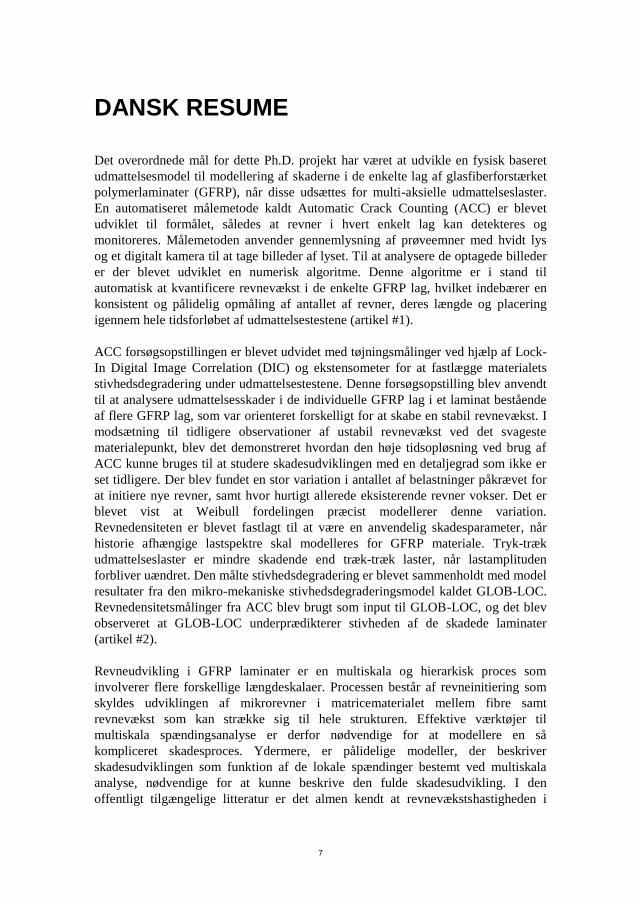
Det overordnede mål for dette Ph.D. projekt har været at udvikle en fysisk baseret
udmattelsesmodel til modellering af skaderne i de enkelte lag af glasfiberforstærket
polymerlaminater (GFRP), når disse udsættes for multi-aksielle udmattelseslaster.
En automatiseret målemetode kaldt Automatic Crack Counting (ACC) er blevet
udviklet til formålet, således at revner i hvert enkelt lag kan detekteres og
monitoreres. Målemetoden anvender gennemlysning af prøveemner med hvidt lys
og et digitalt kamera til at tage billeder af lyset. Til at analysere de optagede billeder
er der blevet udviklet en numerisk algoritme. Denne algoritme er i stand til
automatisk at kvantificere revnevækst i de enkelte GFRP lag, hvilket indebærer en
konsistent og pålidelig opmåling af antallet af revner, deres længde og placering
igennem hele tidsforløbet af udmattelsestestene (artikel #1).
ACC forsøgsopstillingen er blevet udvidet med tøjningsmålinger ved hjælp af Lock-
In Digital Image Correlation (DIC) og ekstensometer for at fastlægge materialets
stivhedsdegradering under udmattelsestestene. Denne forsøgsopstilling blev anvendt
til at analysere udmattelsesskader i de individuelle GFRP lag i et laminat bestående
af flere GFRP lag, som var orienteret forskelligt for at skabe en stabil revnevækst. I
modsætning til tidligere observationer af ustabil revnevækst ved det svageste
materialepunkt, blev det demonstreret hvordan den høje tidsopløsning ved brug af
ACC kunne bruges til at studere skadesudviklingen med en detaljegrad som ikke er
set tidligere. Der blev fundet en stor variation i antallet af belastninger påkrævet for
at initiere nye revner, samt hvor hurtigt allerede eksisterende revner vokser. Det er
blevet vist at Weibull fordelingen præcist modellerer denne variation.
Revnedensiteten er blevet fastlagt til at være en anvendelig skadesparameter, når
historie afhængige lastspektre skal modelleres for GFRP materiale. Tryk-træk
udmattelseslaster er mindre skadende end træk-træk laster, når lastamplituden
forbliver uændret. Den målte stivhedsdegradering er blevet sammenholdt med model
resultater fra den mikro-mekaniske stivhedsdegraderingsmodel kaldet GLOB-LOC.
Revnedensitetsmålinger fra ACC blev brugt som input til GLOB-LOC, og det blev
observeret at GLOB-LOC underprædikterer stivheden af de skadede laminater
(artikel #2).
Revneudvikling i GFRP laminater er en multiskala og hierarkisk proces som
involverer flere forskellige længdeskalaer. Processen består af revneinitiering som
skyldes udviklingen af mikrorevner i matricematerialet mellem fibre samt
revnevækst som kan strække sig til hele strukturen. Effektive værktøjer til
multiskala spændingsanalyse er derfor nødvendige for at modellere en så
kompliceret skadesproces. Ydermere, er pålidelige modeller, der beskriver
skadesudviklingen som funktion af de lokale spændinger bestemt ved multiskala
analyse, nødvendige for at kunne beskrive den fulde skadesudvikling. I den
offentligt tilgængelige litteratur er det almen kendt at revnevækstshastigheden i
CHARACTERIZATION AND MODELLING OF THE MULTIAXIAL FATIGUE RESPONSE OF GLASS FIBRE REINFORCED COMPOSITE MATERIALS
8
GFRP afhænger af revnefrontens lokale lastpåvirkning. Ingen fysisk baserede
modeller til at beskrive indflydelsen af lokal lastpåvirkning på revnevækst
hastigheden i GFRP laminater var tilgængelige i litteraturen. Derfor blev en sådan
fysisk model samt en multiskala tilgang til at evaluere modellen ved brug af
begrænsede computer ressourcer udviklet. Udviklingen af denne model blev
foretaget i samarbejde med Marino Quaresimins forskningsgruppe ved Universitetet
i Padova, Italien. Modellen kræver eksperimentelle data fra to forskellige måder at
laste revnefronten på, således to styrende regressionskurver af Paris’ Lov kan blive
udledt. Baseret på disse regressionskurver er modellen i stand til at forudsige
revnevækstshastigheden for hele spændet af mulige revnefrontslaster, så længe
friktion ikke spiller en væsentlig rolle. Det er blevet vist, hvorledes modellen virker
for både revner i de enkelte GFRP lag i rørgeometrier men også, hvorledes modellen
virker for delamineringer i GFRP- og kulfiberforstærket polymer laminater (artikel
#3).
ACC metoden fra artikel #1, konklusionerne draget i artikel #2 og modellen til at
forudsige hastigheden af revnevækst fra artikel #3 gjorde det muligt at udvikle den
fysisk baserede udmattelsesmodel som er præsenteret i artikel #4.
Hovedbestanddelene i denne model er GLOB-LOC modellen kombineret med en
multi-aksiel initieringsmodel fra litteraturen og revnevækst modellen fra artikel #3.
GLOB-LOC blev udvidet således at modellen kunne beskrive de variationer som
opstår i spændingsfeltet, når revner i GFRP lagene begynder at interagere. Dette var
nødvendigt for det valgte multi-aksielle initieringskriterie og den udviklede
revnevækst model kunne evalueres. Det er blevet demonstreret, hvorledes den fysisk
baserede udmattelsesmodel kan forudsige udviklingen af revnedensiteten i tykke
GFRP lag, når disse udsættes for multi-aksielle udmattelseslaster.

9
CHARACTERIZATION AND MODELLING OF THE MULTIAXIAL FATIGUE RESPONSE OF GLASS FIBRE REINFORCED COMPOSITE MATERIALS
10
PUBLICATIONS
Parts of the research conducted in this project have been published.
Papers published in international journals with peer review:
(Paper #1): Glud JA, Dulieu-Barton JM, Thomsen OT, Overgaard LCT.
Automated counting of off-axis tunnelling cracks using digital image
processing. Compos Sci Technol 2016;125:80–9.
doi:10.1016/j.compscitech.2016.01.019.
(Paper #2): Glud JA, Dulieu-Barton JM, Thomsen OT, Overgaard LCT.
Fatigue damage evolution in GFRP laminates with constrained off-axis
plies. Compos Part A Appl Sci Manuf 2017;95:359–69.
doi:10.1016/j.compositesa.2017.02.005.
Papers submitted to international journals with peer review:
(Paper #3): Glud JA, Carraro PA, Quaresimin M, Dulieu-Barton JM,
Thomsen OT, Overgaard LCT. A physically based model for off-axis
fatigue crack propagation in FRP composites. Submitted;Under Review.
Papers accepted by international journals with peer review:
(Paper #4): Glud JA, Dulieu-Barton JM, Thomsen OT, Overgaard LCT. A
stochastic multiaxial fatigue model for off-axis cracking in FRP laminates.
Accepted; International Journal of Fatigue.
Papers in international conferences with review:
Glud JA, Overgaard LCT, Dulieu-Barton JM, Thomsen OT. Intralaminar
fatigue characterization of GFRP laminate using lock-in DIC and TSA for
use in micro-mechanics based multiaxial fatigue model. 7th Int. Conf.
Compos. Test. Model Identif. (CompTest 2015), Getafe, Spain, 2015. (won
best student oral presentation award)
Glud JA, Dulieu-Barton JM, Thomsen OT, Overgaard LCT. Micro-
mechanical multiaxial fatigue model for crack density evolution and
stiffness degradation. 20th Int. Conf. Compos. Mater. (ICCM20),
Copenhagen, Denmark, 2015, p. 1204–1.
Glud JA, Dulieu-Barton JM, Thomsen OT, Overgaard LCT. A new white
light imaging approach for intralaminar fatigue characterisation of GFRP.
10th Int. Conf. Exp. Mech., (ICEM-10), Edinburgh, UK, 2015. (won
Young Stress Analysts award)
Glud JA, Dulieu-Barton JM, Thomsen OT, Overgaard LCT. Data rich
multiaxial fatigue characterisation of off-axis layers in GFRP laminates.
BSSM’s First Postgrad. Exp. Mech. Conf., Southampton, UK, 2015.
Glud JA, Dulieu-Barton JM, Thomsen OT, Overgaard LCT. Efficient
micro-mechanical multiaxial fatigue testing and modelling for GFRP
11
laminates. Eur. Conf. Compos. Mater., (ECCM-16), Munich, Germany,
2016.

13
TABLE OF CONTENTS
Chapter 1. Background and motivation ........................................................................... 15
1.1. Research objectives ....................................................................................... 17
1.2. Novelty .......................................................................................................... 18
1.3. Structure of thesis .......................................................................................... 19
Chapter 2. Experimental method to characterise fatigue damage evolution
(PAPER #1) ......................................................................................................................... 20
2.1. Test setup and image acquisition .................................................................. 22
2.2. The ACC methodology ................................................................................. 23
2.3. Validation ...................................................................................................... 26
2.4. Conclusions ................................................................................................... 28
Chapter 3. Quantifying the fatigue damage evolution in GFRP laminates
(Paper #2) ............................................................................................................................ 29
3.1. Material and experiment ............................................................................... 31
3.2. Analysis of crack density results ................................................................... 31
3.3. Analysis of crack initiation and crack growth ............................................... 36
3.4. Conclusions ................................................................................................... 40
Chapter 4. Micro-mechanical models for predicting stiffness degradation ................. 42
4.1. GLOB-LOC .................................................................................................. 43
4.2. Comparison with stiffness degradation measurement ................................... 45
4.3. Extending GLOB-LOC ................................................................................. 47
4.4. Conclusions ................................................................................................... 50
Chapter 5. A mixed-mode propagation model for off-axis cracks (PAPER #3) ........... 52
5.1. Model ............................................................................................................ 53
5.2. Results ........................................................................................................... 55
5.3. Conclusions ................................................................................................... 62
Chapter 6. A multiaxial fatigue model for off-axis crack evolution (PAPER #4) ......... 63
6.1. Model ............................................................................................................ 64
6.2. Results ........................................................................................................... 68
6.3. Conclusions ................................................................................................... 68
Chapter 7. Summary of scientific contributions .............................................................. 70
CHARACTERIZATION AND MODELLING OF THE MULTIAXIAL FATIGUE RESPONSE OF GLASS FIBRE REINFORCED COMPOSITE MATERIALS
14
Chapter 8. Future work ..................................................................................................... 72
Literature list ...................................................................................................................... 74
15
CHAPTER 1. BACKGROUND AND
MOTIVATION
Glass fibre reinforced polymers (GFRP) were invented during the 1940’s and when
compared to e.g. steel this can be considered to be a relatively new type of material.
It consists of glass fibres hold together by a matrix material made from polymers. A
rapid growth in the use of GFRP materials has been observed since its invention and
in 2014 95% of the world wide total production of FRP materials was GFRP [1].
GFRP laminates belong to a specific class of GFRP material where glass fabrics
made from continuous fibres are stacked on top of each other and impregnated by a
polymer resin to create a solid composite material. GFRP laminates are being used
increasingly in structural components where the strength to weight ratio is
important. Accurate models that can predict when the material fails are required to
fully utilise the strength to weight ratio of GFRP laminates.
To predict failure of GFRP laminates a wide range of models has been proposed for
quasi-static load cases. The world-wide-failure-exercise reviewed several of these
models [2] and from this review it was pointed out that even the best performing
models showed a poor predictive capability for several of the test cases.
Besides structural GFRP components susceptible to quasi-static failure, GFRP
laminates are also being used increasingly in structural components subjected to
fatigue loading. Examples of such components are modern wind turbine blades,
which utilise large amounts of GFRP laminate materials. The gravitational, inertial
and aerodynamic loads acting on a wind turbine blade are fatigue loads. Wind
turbine blades have a service life of more than 20 years, and are therefore subjected
to ultra-high cycle fatigue. The fatigue loading experienced by the GFRP laminates
is multiaxial and causes strength and stiffness degradation, which leads to a finite
lifetime of the blades. Modern wind turbine blades are so large that gravitational and
inertial loads have started to dominate more than aerodynamic loads [3]. This means
that wind turbine blades are now weight critical structures and therefore requires
accurate fatigue models to utilise the material in the most efficient manner and hence
save weight.
As for quasi-static loads, several models for predicting material failure of GFRP
laminates subjected to fatigue loading have been proposed. The vast majority of
these models are phenomenological and the most widely applied design methods
used in e.g. the wind turbine industry makes use of these phenomenological models
[4]. The phenomenological models currently proposed for GFRP laminates and the
phenomenological models used by standards [4–6] are highly inspired by empirical
models developed for metals. The models rely on stress versus life (S-N) diagrams
as proposed by A. Wöhler for steel and account for the influence of mean stress
CHARACTERIZATION AND MODELLING OF THE MULTIAXIAL FATIGUE RESPONSE OF GLASS FIBRE REINFORCED COMPOSITE MATERIALS
16
effects using constant life diagrams somewhat similar to the Goodman diagram
approach developed by J. Goodman for steel. This appears to be a questionable
approach considering the fact that the actual fatigue failure modes of the two types
of materials are not similar. In steel, it is commonly recognised that the fatigue crack
growth is explained by slip deformations of more than one slip plane which will
cause crack extension and leave visible striations on crack surfaces [7,8]. When the
crack reaches a critical length it becomes unstable resulting in a sudden catastrophic
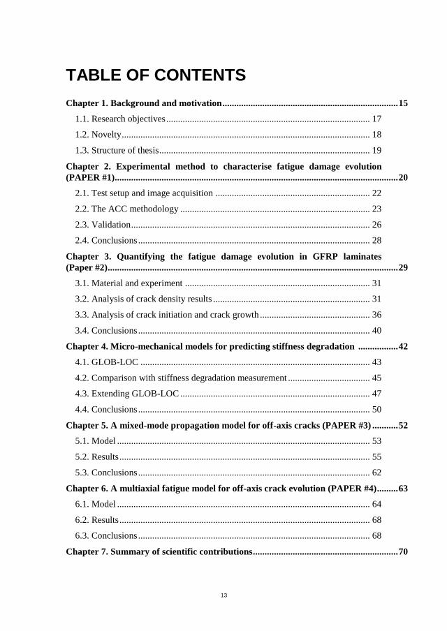
failure. Usually, the fatigue failure of GFRP laminates is not sudden as the material
steadily degrades due to a series of subcritical failure modes. These failure modes
and when they occur during the fatigue life of a GFRP laminate are schematically
illustrated in Figure 1.
Figure 1: Usual damage modes observed during fatigue loading of GFRP laminates
[9].
In GFRP laminates, the first damage mode usually takes the form of matrix cracking
(also known as off-axis cracks or Inter Fibre Failure (IFF)) tunnelling through the
laminate layers, followed by delamination and fibre breakage leading to ultimate
structural failure. Thus, the fatigue damage process of GFRP is very different from
the fatigue damage process in steel.
In a recent review of phenomenological fatigue models [10] for composite lamintes
it was found that all reviewed models for several load cases provided overly
conservative predictions and for several other load cases provided highly non-
conservative predictions. Therefore, Quaresimin et al. [10] have questioned the
general validity of the reviewed models and highlight the need for new and more
17
advanced models in order to use the materials in a more efficient manner.
Quaresimin et al. [10] stress that research within the field of fatigue of laminated
composites should move in the direction to improve the understanding of the
underlying damage mechanisms, and further to include these damage mechanisms
in future predictive models. The potential outcome of such an approach is envisaged
to be generally applicable models, which would limit the need for experimental
testing, provide enhanced information of the actual damage states within the
material, and finally provide better lifetime predictions. All of these outcomes may
help the composites industry in creating lighter, cheaper and more efficient
composite products.
Fatigue models for composite laminates, which incorporate actual damage
mechanisms, are still in their infant stage [11], since they are limited to simple
laminate configurations and restricted to simple fatigue load cases. The reason why
this branch of fatigue models are still in their infant stage despite their appealing
envisaged outcome could be explained by the limited amount of experimental
studies of actual damage mechanisms [12] and the fact that fatigue damage is a
complicated multi-scale and hierarchical process occurring at several different
length scales [13]. This, underpins the need for advancing both the experimental and
the modelling research fields in order to reach the ultimate goal of having models
capable of providing safe and reliable fatigue life predictions for composite
laminates.
1.1. RESEARCH OBJECTIVES
The overall objective of the Ph.D. project is to develop an improved understanding
of failure mechanisms in multi-directional GFRP laminates and to propose a fatigue
life prediction model for GFRP laminates, which models the actual fatigue damage
evolution process. This includes the following sub-goals of the research:
A new method to characterise multiaxial fatigue in GFRP laminates.
Experimental investigation of off-axis cracks in GFRP laminates under
multiaxial fatigue loading.
Physically based modelling of off-axis cracks in GFRP laminates and its
influence on the in-plane elastic properties of the damaged laminate.
The anticipated outcome is a multiaxial fatigue model capable of describing the
actual off-axis crack damage mechanisms in GFRP laminates and an efficient test
campaign strategy to fatigue characterise a GFRP material.
CHARACTERIZATION AND MODELLING OF THE MULTIAXIAL FATIGUE RESPONSE OF GLASS FIBRE REINFORCED COMPOSITE MATERIALS
18
The following chapters summarise the research conducted during this Ph.D. project
and the conclusions drawn based on the research.
1.2. NOVELTY
The research conducted during this Ph.D. project has provided several novel
contributions within the field of multiaxial fatigue testing and modelling of fatigue
damage in multidirectional GFRP laminates. The novelties are described in detail in
the four appended papers and can be summarised as follows:
A novel in-situ experimental technique named Automatic Crack Counting
(ACC) used to quantify fatigue damage in off-axis plies has been proposed.
The method employs transilluminated white light imaging and digital
image processing to automatically quantify the damage state. The in-situ
and automatic nature of the method results in a high temporal resolution of
the damage development in the tested laminates. (Paper #1)
The fatigue damage evolution in GFRP off-axis plies has been studied in
detail using the novel experimental technique, ACC (Paper #2). The tested
off-axis plies have been subjected to different fatigue loading conditions
taking into account both R-ratio effects and variable amplitude loading.
Several new conclusions about how fatigue damage develops in
multidirectional laminates have been drawn. The crack density was found
to be a suitable damage measure for a low-high sequence of variable
amplitude block loading. T-T loading results in a higher crack density than
is the case for C-T loading for the same load amplitude. The Weibull
distribution effectively models the stochastic nature of off-axis crack
initiation and growth and the shape parameter of the Weibull distribution is
independent of stress level and ply thickness. Furthermore, by using ACC
it has been shown how to efficiently derive material parameters, which
describe the off-axis crack damage evolution process.
A physically based multi-scale model for modelling the influence of mixed-
mode loading on the off-axis crack propagation rate under fatigue has been
proposed (Paper #3). The local stress state in front of off-axis cracks was
found to influence the observed microscopic damage modes responsible for
crack propagation. Equivalent energy release rates based on the stress state
associated with each of the observed damage modes were proposed. These
equivalent energy release rates were found to be applicable for establishing
two Paris’ Law master curves, which can be used to describe the crack
growth rate under different mixed-mode loading conditions.
A new stochastic multi-scale fatigue model for modelling the off-axis crack
evolution in multi-directional laminates has been developed (Paper #4).
19
The model is based on the GLOB-LOC [14] damage modelling framework,
which in this project has been extended, so the multi-scale stress state of
interacting cracks in the damaged plies can be accounted for. The model
only requires two different laminate configurations to be tested in fatigue to
calibrate the material parameters.
1.3. STRUCTURE OF THESIS
This Ph.D. thesis is based on four scientific papers, where Paper #1 and Paper #2
have been published in peer reviewed scientific journals and Paper #3 and Paper #4
have been submitted to peer reviewed scientific journals. The following chapters of
this thesis present an extended summary of the research conducted and describes
how the four papers are connected. The four papers are appended as annexes.
The extended summary is structured as follows:
Chapter 1: Background and motivation for the project along with novelty
claims and research objectives
Chapter 2: Summary of Paper #1, where a novel experimental method to
quantify the fatigue damage evolution in GFRP laminates is presented
Chapter 3: Summary of Paper #2, where the novel experimental method
from Paper #1 was used to study the damage evolution in an MD laminate
containing off-axis plies
Chapter 4: Benchmark of a state-of-the-art off-axis damage model against
experimental measurements (Paper #2) and extension of the same damage
model to include additional stress analysis capabilities (Paper #4)
Chapter 5: Summary of Paper #3, which describes the development of a
multiscale model to predict the crack growth rate of off-axis cracks under
mixed-mode fatigue loadings
Chapter 6: Summary of Paper #4, where a multiaxial fatigue model used to
predict the off-axis crack evolution in MD laminates is described
Chapter 7: Summary of scientific contributions
Chapter 8: Suggestions for future work
CHARACTERIZATION AND MODELLING OF THE MULTIAXIAL FATIGUE RESPONSE OF GLASS FIBRE REINFORCED COMPOSITE MATERIALS
20
CHAPTER 2. EXPERIMENTAL METHOD
TO CHARACTERISE FATIGUE
DAMAGE EVOLUTION (PAPER #1)
Many different types of intralaminar micro damage may evolve during the fatigue
life of laminated composites. One of the most common damage modes is
intralaminar matrix cracks in the laminate layers, which are through-the-thickness
(tunnelling) cracks in the matrix and fibre debonds propagating along the fibres.
These cracks are commonly called off-axis matrix cracks in the research community.
It is particularly important to predict the off-axis crack damage mode, since these
cracks promote other damage modes such as delamination and fibre breakage
[15,16] and are linked directly to the stiffness degradation observed in composite
laminates during fatigue loading [17–20]. However, widely accepted models for
predicting the off-axis crack evolution under either quasi-static or fatigue loading are
yet to be proposed. The third world-wide failure exercise [21] focuses on the ability
of currently existing models to predict off-axis crack evolution under quasi-static
loading and the exercise has yet to be concluded. Furthermore, for the case of
fatigue loading the need for such models is strongly emphasised in the recent review
of phenomenological fatigue models in [10].
Even though off-axis cracks has received significant attention in literature, most
experimental studies are limited with regard to their scope and coverage, and there is
no general consensus on how the off-axis crack evolution should be measured,
quantified and reported for laminated composites. Several different experimental
techniques have been reported successful in detecting and measuring the off-axis
crack evolution. These techniques include: thermoelastic stress analysis (TSA) [22],
digital image correlation (DIC) [23], acoustic emission [24], X-ray [25], X-ray
Computed Tomography (CT) [26], Ultrasonic C-scan [25], edge-examination [27]
and transilluminated white light imaging (TWLI) [15,18–20,28]. Each technique has
different capabilities when it comes to quantifying off-axis crack damage evolution.
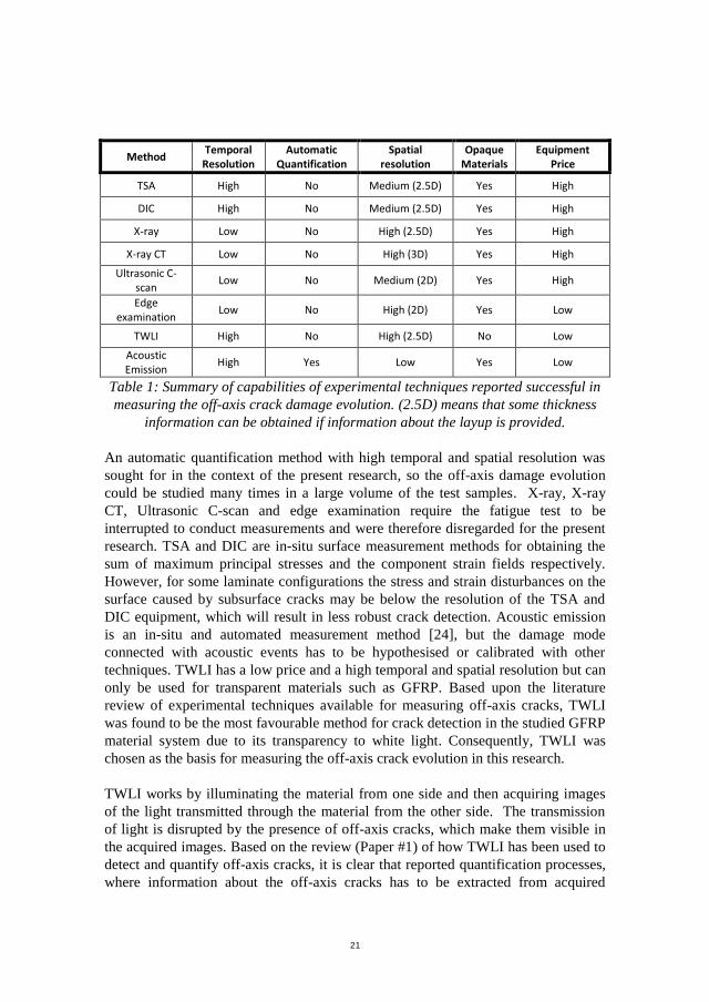
The different techniques are summarised in Table 1 according to a set of assessment
criteria that are deemed important for the characterisation of off-axis crack evolution
carried out in the present Ph.D. project.
21
Method Temporal
Resolution Automatic
Quantification Spatial
resolution Opaque
Materials Equipment
Price
TSA High No Medium (2.5D) Yes High
DIC High No Medium (2.5D) Yes High
X-ray Low No High (2.5D) Yes High
X-ray CT Low No High (3D) Yes High
Ultrasonic C-scan
Low No Medium (2D) Yes High
Edge examination
Low No High (2D) Yes Low
TWLI High No High (2.5D) No Low
Acoustic Emission
High Yes Low Yes Low
Table 1: Summary of capabilities of experimental techniques reported successful in
measuring the off-axis crack damage evolution. (2.5D) means that some thickness
information can be obtained if information about the layup is provided.
An automatic quantification method with high temporal and spatial resolution was
sought for in the context of the present research, so the off-axis damage evolution
could be studied many times in a large volume of the test samples. X-ray, X-ray
CT, Ultrasonic C-scan and edge examination require the fatigue test to be
interrupted to conduct measurements and were therefore disregarded for the present
research. TSA and DIC are in-situ surface measurement methods for obtaining the
sum of maximum principal stresses and the component strain fields respectively.
However, for some laminate configurations the stress and strain disturbances on the
surface caused by subsurface cracks may be below the resolution of the TSA and
DIC equipment, which will result in less robust crack detection. Acoustic emission
is an in-situ and automated measurement method [24], but the damage mode
connected with acoustic events has to be hypothesised or calibrated with other
techniques. TWLI has a low price and a high temporal and spatial resolution but can
only be used for transparent materials such as GFRP. Based upon the literature
review of experimental techniques available for measuring off-axis cracks, TWLI
was found to be the most favourable method for crack detection in the studied GFRP
material system due to its transparency to white light. Consequently, TWLI was
chosen as the basis for measuring the off-axis crack evolution in this research.
TWLI works by illuminating the material from one side and then acquiring images
of the light transmitted through the material from the other side. The transmission
of light is disrupted by the presence of off-axis cracks, which make them visible in
the acquired images. Based on the review (Paper #1) of how TWLI has been used to
detect and quantify off-axis cracks, it is clear that reported quantification processes,
where information about the off-axis cracks has to be extracted from acquired
CHARACTERIZATION AND MODELLING OF THE MULTIAXIAL FATIGUE RESPONSE OF GLASS FIBRE REINFORCED COMPOSITE MATERIALS
22
images, were manual and visual counting of cracks. The crack state generally
consists of many cracks, which are unevenly distributed in the region of interest [9,
26]. Therefore, manual and visual counting is labour intensive and difficult to do in
a consistent and reproducible manner. This limits the scope and size of studies and
leads to a relatively poor temporal resolution of the crack state. Moreover, the
material properties extracted from experimental tests and the drawn conclusion may
not be valid, if the crack counting is not done in a consistent manner due to human
mistakes in the counting process. It was therefore clear at the beginning of this Ph.D.
project that there is a great need for developing an automated approach to quantify
the crack state, so accurate and reproducible quantifications could be obtained in a
fast, reliable and efficient manner.
2.1. TEST SETUP AND IMAGE ACQUISITION
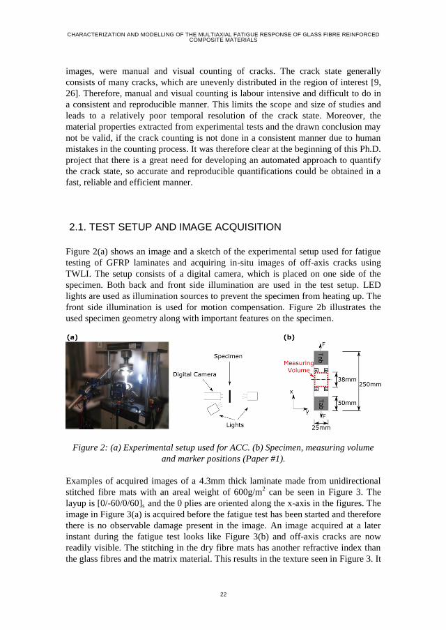
Figure 2(a) shows an image and a sketch of the experimental setup used for fatigue
testing of GFRP laminates and acquiring in-situ images of off-axis cracks using
TWLI. The setup consists of a digital camera, which is placed on one side of the
specimen. Both back and front side illumination are used in the test setup. LED
lights are used as illumination sources to prevent the specimen from heating up. The
front side illumination is used for motion compensation. Figure 2b illustrates the
used specimen geometry along with important features on the specimen.
Figure 2: (a) Experimental setup used for ACC. (b) Specimen, measuring volume
and marker positions (Paper #1).
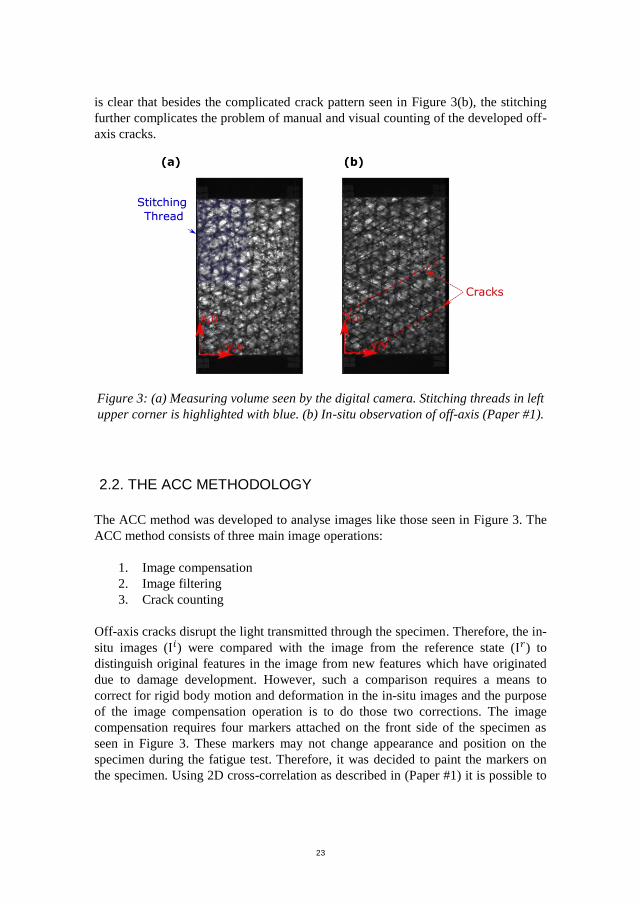
Examples of acquired images of a 4.3mm thick laminate made from unidirectional
stitched fibre mats with an areal weight of 600g/m2 can be seen in Figure 3. The
layup is [0/-60/0/60]s and the 0 plies are oriented along the x-axis in the figures. The
image in Figure 3(a) is acquired before the fatigue test has been started and therefore
there is no observable damage present in the image. An image acquired at a later
instant during the fatigue test looks like Figure 3(b) and off-axis cracks are now
readily visible. The stitching in the dry fibre mats has another refractive index than
the glass fibres and the matrix material. This results in the texture seen in Figure 3. It
23
is clear that besides the complicated crack pattern seen in Figure 3(b), the stitching
further complicates the problem of manual and visual counting of the developed off-
axis cracks.
Figure 3: (a) Measuring volume seen by the digital camera. Stitching threads in left
upper corner is highlighted with blue. (b) In-situ observation of off-axis (Paper #1).
2.2. THE ACC METHODOLOGY
The ACC method was developed to analyse images like those seen in Figure 3. The
ACC method consists of three main image operations:
1. Image compensation
2. Image filtering
3. Crack counting
Off-axis cracks disrupt the light transmitted through the specimen. Therefore, the in-
situ images (I𝑖) were compared with the image from the reference state (I𝑟) to
distinguish original features in the image from new features which have originated
due to damage development. However, such a comparison requires a means to
correct for rigid body motion and deformation in the in-situ images and the purpose
of the image compensation operation is to do those two corrections. The image
compensation requires four markers attached on the front side of the specimen as
seen in Figure 3. These markers may not change appearance and position on the
specimen during the fatigue test. Therefore, it was decided to paint the markers on
the specimen. Using 2D cross-correlation as described in (Paper #1) it is possible to
CHARACTERIZATION AND MODELLING OF THE MULTIAXIAL FATIGUE RESPONSE OF GLASS FIBRE REINFORCED COMPOSITE MATERIALS
24
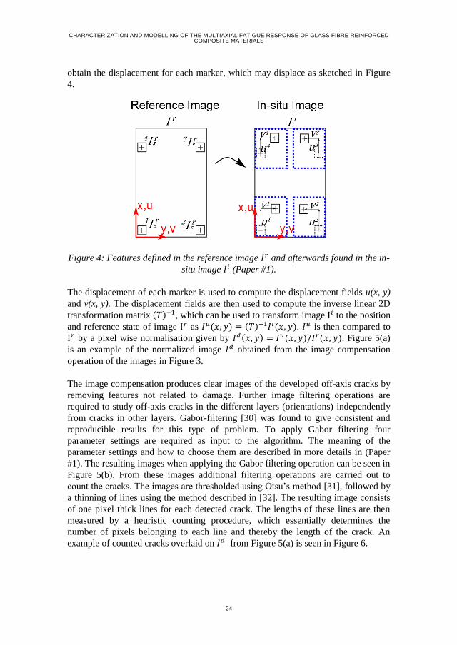
obtain the displacement for each marker, which may displace as sketched in Figure
4.
Figure 4: Features defined in the reference image 𝐼𝑟 and afterwards found in the in-
situ image 𝐼𝑖 (Paper #1).
The displacement of each marker is used to compute the displacement fields u(x, y)
and v(x, y). The displacement fields are then used to compute the inverse linear 2D
transformation matrix (𝑇)−1, which can be used to transform image I𝑖 to the position
and reference state of image I𝑟 as 𝐼𝑢(𝑥, 𝑦) = (𝑇)−1𝐼𝑖(𝑥, 𝑦). 𝐼𝑢 is then compared to
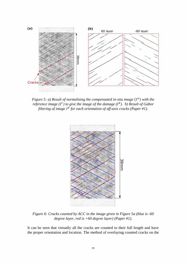
I𝑟 by a pixel wise normalisation given by 𝐼𝑑(𝑥, 𝑦) = 𝐼𝑢(𝑥, 𝑦)/𝐼𝑟(𝑥, 𝑦). Figure 5(a)
is an example of the normalized image 𝐼𝑑 obtained from the image compensation
operation of the images in Figure 3.
The image compensation produces clear images of the developed off-axis cracks by
removing features not related to damage. Further image filtering operations are
required to study off-axis cracks in the different layers (orientations) independently
from cracks in other layers. Gabor-filtering [30] was found to give consistent and
reproducible results for this type of problem. To apply Gabor filtering four
parameter settings are required as input to the algorithm. The meaning of the
parameter settings and how to choose them are described in more details in (Paper
#1). The resulting images when applying the Gabor filtering operation can be seen in
Figure 5(b). From these images additional filtering operations are carried out to
count the cracks. The images are thresholded using Otsu’s method [31], followed by
a thinning of lines using the method described in [32]. The resulting image consists
of one pixel thick lines for each detected crack. The lengths of these lines are then
measured by a heuristic counting procedure, which essentially determines the
number of pixels belonging to each line and thereby the length of the crack. An
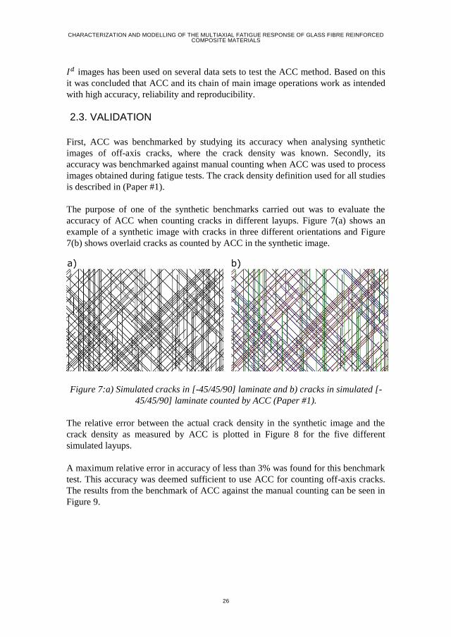
example of counted cracks overlaid on 𝐼𝑑 from Figure 5(a) is seen in Figure 6.
25
Figure 6: Cracks counted by ACC in the image given in Figure 5a (blue is -60
degree layer, red is +60 degree layer) (Paper #1).
It can be seen that virtually all the cracks are counted to their full length and have
the proper orientation and location. The method of overlaying counted cracks on the
Figure 5: a) Result of normalising the compensated in-situ image (𝐼𝑢) with the
reference image (𝐼𝑟) to give the image of the damage (𝐼𝑑). b) Result of Gabor
filtering of image 𝐼𝑑 for each orientation of off-axis cracks (Paper #1).
CHARACTERIZATION AND MODELLING OF THE MULTIAXIAL FATIGUE RESPONSE OF GLASS FIBRE REINFORCED COMPOSITE MATERIALS
26
𝐼𝑑 images has been used on several data sets to test the ACC method. Based on this
it was concluded that ACC and its chain of main image operations work as intended
with high accuracy, reliability and reproducibility.
2.3. VALIDATION
First, ACC was benchmarked by studying its accuracy when analysing synthetic
images of off-axis cracks, where the crack density was known. Secondly, its
accuracy was benchmarked against manual counting when ACC was used to process
images obtained during fatigue tests. The crack density definition used for all studies
is described in (Paper #1).
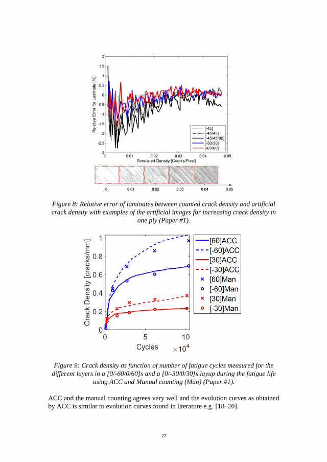
The purpose of one of the synthetic benchmarks carried out was to evaluate the
accuracy of ACC when counting cracks in different layups. Figure 7(a) shows an
example of a synthetic image with cracks in three different orientations and Figure
7(b) shows overlaid cracks as counted by ACC in the synthetic image.
Figure 7:a) Simulated cracks in [-45/45/90] laminate and b) cracks in simulated [-
45/45/90] laminate counted by ACC (Paper #1).
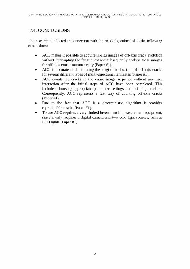
The relative error between the actual crack density in the synthetic image and the
crack density as measured by ACC is plotted in Figure 8 for the five different
simulated layups.
A maximum relative error in accuracy of less than 3% was found for this benchmark
test. This accuracy was deemed sufficient to use ACC for counting off-axis cracks.
The results from the benchmark of ACC against the manual counting can be seen in
Figure 9.
27
Figure 8: Relative error of laminates between counted crack density and artificial
crack density with examples of the artificial images for increasing crack density in
one ply (Paper #1).
Figure 9: Crack density as function of number of fatigue cycles measured for the
different layers in a [0/-60/0/60]s and a [0/-30/0/30]s layup during the fatigue life
using ACC and Manual counting (Man) (Paper #1).
ACC and the manual counting agrees very well and the evolution curves as obtained
by ACC is similar to evolution curves found in literature e.g. [18–20].
CHARACTERIZATION AND MODELLING OF THE MULTIAXIAL FATIGUE RESPONSE OF GLASS FIBRE REINFORCED COMPOSITE MATERIALS
28
2.4. CONCLUSIONS
The research conducted in connection with the ACC algorithm led to the following
conclusions:
ACC makes it possible to acquire in-situ images of off-axis crack evolution
without interrupting the fatigue test and subsequently analyse these images
for off-axis cracks automatically (Paper #1).
ACC is accurate in determining the length and location of off-axis cracks
for several different types of multi-directional laminates (Paper #1).
ACC counts the cracks in the entire image sequence without any user
interaction after the initial steps of ACC have been completed. This
includes choosing appropriate parameter settings and defining markers.
Consequently, ACC represents a fast way of counting off-axis cracks
(Paper #1).
Due to the fact that ACC is a deterministic algorithm it provides
reproducible results (Paper #1).
To use ACC requires a very limited investment in measurement equipment,
since it only requires a digital camera and two cold light sources, such as
LED lights (Paper #1).
29
CHAPTER 3. QUANTIFYING THE
FATIGUE DAMAGE EVOLUTION IN
GFRP LAMINATES (PAPER #2)
The increasing use of fibre reinforced polymer (FRP) laminates in the industry has
led to several experimental campaigns aimed at quantifying the fatigue damage
evolution in FRP laminates as function of the multiple factors (e.g. number of load
reversals, magnitude of amplitude stress, stress ratio, voids, fibre volume fraction
etc.) that influence the fatigue life of a laminated composite. Several studies have
been conducted to characterise UD laminates, see e.g. [33,34]. The characterisation
related to fatigue studies includes determination of constitutive properties (e.g.
𝐸11, 𝐸22, 𝐺12 and 𝜈12), strength properties (e.g. tensile and compressive strength
parallel and orthogonal to fibre direction as well as shear strength) and fatigue
properties (e.g. S-N curves for different stress ratios). By characterising UD
laminates it is possible to discard the influence of different layups. The derived
properties can then be regarded as material properties for the basic building block of
a MD laminate – the single UD ply. It is well established in the composite
community that classical laminate theory (CLT) [35] provides accurate predictions
of arbitrary layups based on information of UD constitutive properties. Several
researchers have proposed fatigue models based on derived constitutive, strength
and fatigue properties for UD plies as seen in e.g. the phenomenological models
reviewed in [10] and in the more advanced progressive damage models [36–39]. A
fundamental assumption in all of these models is that the fatigue properties derived
for the UD laminate are representative for the case when the UD laminate is
embedded in an MD laminate. The models then use stress based analysis from either
CLT analysis or FE analysis to predict when plies fail. The influence of ply failure
on overall performance of the laminate is then accounted for in the progressive
damage models by empirical degradation rules involving several non-measurable
empirical constants.
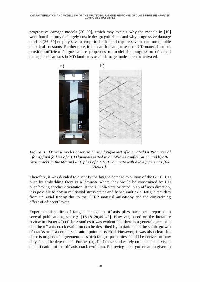
The fatigue damage evolution in MD laminates as reported in e.g. [15,18–20,40–42]
is different from that of derived fatigue properties from UD laminates. An example
of the damage mode observed in a UD laminate is shown in Figure 10(a). Unstable
propagation of a single crack occurs in a laminate consisting entirely of UD plies,
which is not accompanied by progressive stiffness degradation prior to final failure.
When constraining plies are present, as is the case for UD plies embedded in MD
laminates, initiation of several cracks and stable crack propagation (as shown in
Figure 10(b)) are observed. These damage mechanisms lead to a progressive
stiffness degradation of the laminate during the fatigue test. This contradicts the
fundamental assumption used in the phenomenological models [10] and in the
CHARACTERIZATION AND MODELLING OF THE MULTIAXIAL FATIGUE RESPONSE OF GLASS FIBRE REINFORCED COMPOSITE MATERIALS
30
progressive damage models [36–39], which may explain why the models in [10]
were found to provide largely unsafe design guidelines and why progressive damage
models [36–39] employ several empirical rules and require several non-measurable
empirical constants. Furthermore, it is clear that fatigue tests on UD material cannot
provide sufficient fatigue failure properties to model the progression of actual
damage mechanisms in MD laminates as all damage modes are not activated.
Figure 10: Damage modes observed during fatigue test of laminated GFRP material
for a) final failure of a UD laminate tested in an off-axis configuration and b) off-
axis cracks in the 60° and -60° plies of a GFRP laminate with a layup given as [0/-
60/0/60]s.
Therefore, it was decided to quantify the fatigue damage evolution of the GFRP UD
plies by embedding them in a laminate where they would be constrained by UD
plies having another orientation. If the UD plies are oriented in an off-axis direction,
it is possible to obtain multiaxial stress states and hence multiaxial fatigue test data
from uni-axial testing due to the GFRP material anisotropy and the constraining
effect of adjacent layers.
Experimental studies of fatigue damage in off-axis plies have been reported in
several publications, see e.g. [15,18–20,40–42]. However, based on the literature
review in (Paper #2) of these studies it was evident that there is a general agreement
that the off-axis crack evolution can be described by initiation and the stable growth
of cracks until a certain saturation point is reached. However, it was also clear that
there is no general agreement on which fatigue properties should be derived or how
they should be determined. Further on, all of these studies rely on manual and visual
quantification of the off-axis crack evolution. Following the argumentation given in
31
Chapter 2, this way of obtaining data may be influenced by human error and thereby
give biased results. Therefore, it was decided to use ACC for studying as well as
quantifying the fatigue damage evolution of the GFRP material.
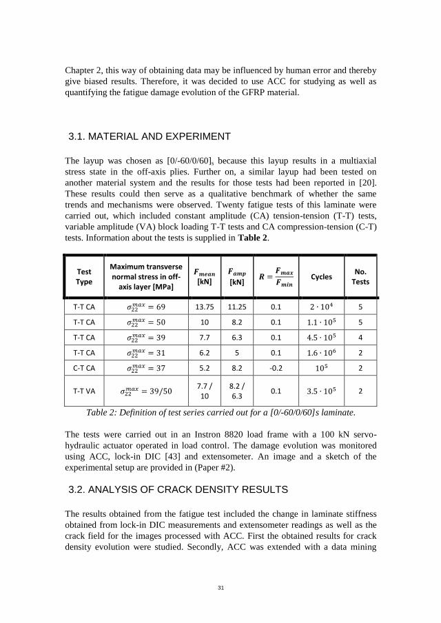
3.1. MATERIAL AND EXPERIMENT
The layup was chosen as [0/-60/0/60]s because this layup results in a multiaxial
stress state in the off-axis plies. Further on, a similar layup had been tested on
another material system and the results for those tests had been reported in [20].
These results could then serve as a qualitative benchmark of whether the same
trends and mechanisms were observed. Twenty fatigue tests of this laminate were
carried out, which included constant amplitude (CA) tension-tension (T-T) tests,
variable amplitude (VA) block loading T-T tests and CA compression-tension (C-T)
tests. Information about the tests is supplied in Table 2.
Test Type
Maximum transverse normal stress in off-
axis layer [MPa]
𝑭𝒎𝒆𝒂𝒏 [kN]
𝑭𝒂𝒎𝒑
[kN] 𝑹 =
𝑭𝒎𝒂𝒙
𝑭𝒎𝒊𝒏 Cycles
No. Tests
T-T CA 𝜎22𝑚𝑎𝑥 = 69 13.75 11.25 0.1 2 ∙ 104 5
T-T CA 𝜎22𝑚𝑎𝑥 = 50 10 8.2 0.1 1.1 ∙ 105 5
T-T CA 𝜎22𝑚𝑎𝑥 = 39 7.7 6.3 0.1 4.5 ∙ 105 4
T-T CA 𝜎22𝑚𝑎𝑥 = 31 6.2 5 0.1 1.6 ∙ 106 2
C-T CA 𝜎22𝑚𝑎𝑥 = 37 5.2 8.2 -0.2 105 2
T-T VA 𝜎22𝑚𝑎𝑥 = 39/50
7.7 / 10
8.2 / 6.3
0.1 3.5 ∙ 105 2
Table 2: Definition of test series carried out for a [0/-60/0/60]s laminate.
The tests were carried out in an Instron 8820 load frame with a 100 kN servo-
hydraulic actuator operated in load control. The damage evolution was monitored
using ACC, lock-in DIC [43] and extensometer. An image and a sketch of the
experimental setup are provided in (Paper #2).
3.2. ANALYSIS OF CRACK DENSITY RESULTS
The results obtained from the fatigue test included the change in laminate stiffness
obtained from lock-in DIC measurements and extensometer readings as well as the
crack field for the images processed with ACC. First the obtained results for crack
density evolution were studied. Secondly, ACC was extended with a data mining
CHARACTERIZATION AND MODELLING OF THE MULTIAXIAL FATIGUE RESPONSE OF GLASS FIBRE REINFORCED COMPOSITE MATERIALS
32
approach such that initiation and stable crack growth of the developed off-axis
cracks could be detected and quantified.
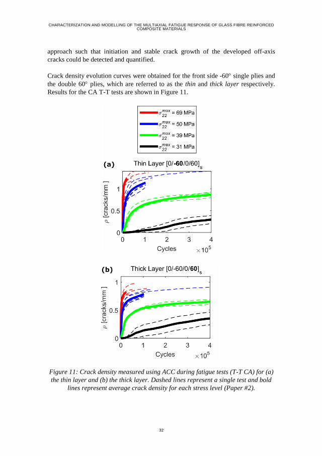
Crack density evolution curves were obtained for the front side -60 single plies and
the double 60 plies, which are referred to as the thin and thick layer respectively.
Results for the CA T-T tests are shown in Figure 11.
Figure 11: Crack density measured using ACC during fatigue tests (T-T CA) for (a)
the thin layer and (b) the thick layer. Dashed lines represent a single test and bold
lines represent average crack density for each stress level (Paper #2).
33
The results are consistent with the results reported in [20]. According to the idea of a
Characteristic Damage State (CDS) [44], there can only be one saturation value for a
particular layer. However, the slopes of the curves flatten, i.e. saturation, at a
different stress levels, even though a clear asymptotic saturation is not achieved.
Therefore a new terminology for this saturation value for each stress level was
adopted by referring to it as the ‘apparent saturation value’. The crack density
observed for the thick layer is lower than the crack density observed for the thin
layer. This occurs due to difference in the shielding effect as explained in (Paper
#2).
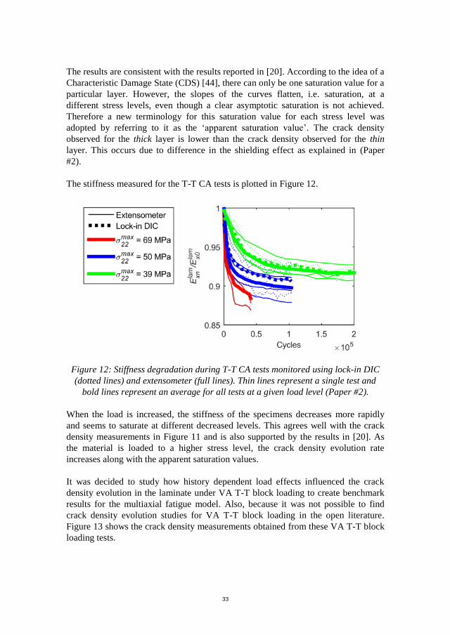
The stiffness measured for the T-T CA tests is plotted in Figure 12.
Figure 12: Stiffness degradation during T-T CA tests monitored using lock-in DIC
(dotted lines) and extensometer (full lines). Thin lines represent a single test and
bold lines represent an average for all tests at a given load level (Paper #2).
When the load is increased, the stiffness of the specimens decreases more rapidly
and seems to saturate at different decreased levels. This agrees well with the crack
density measurements in Figure 11 and is also supported by the results in [20]. As
the material is loaded to a higher stress level, the crack density evolution rate
increases along with the apparent saturation values.
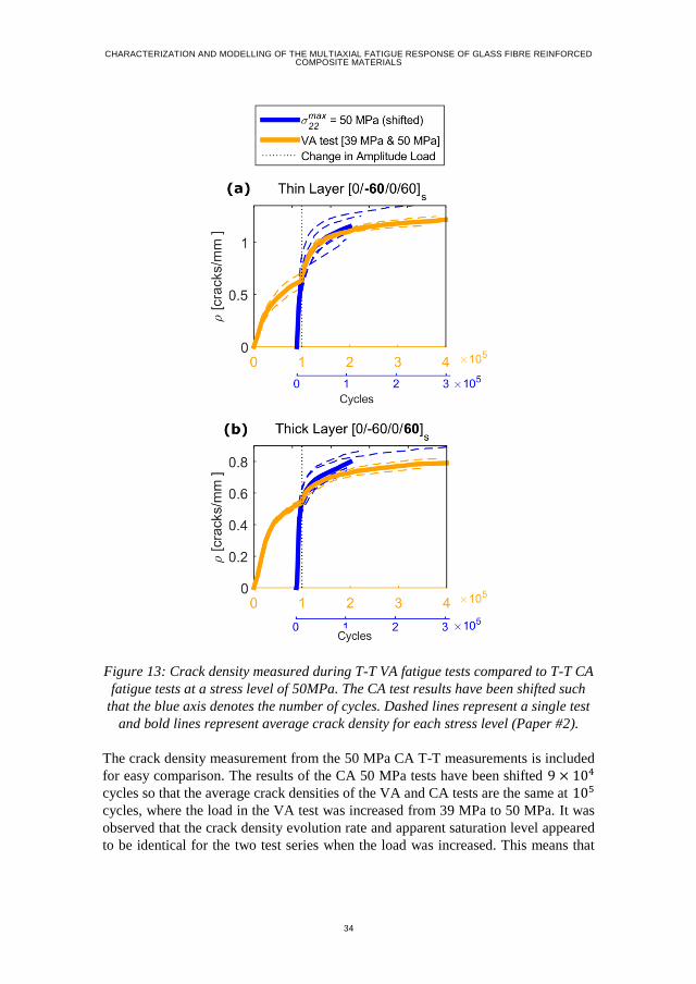
It was decided to study how history dependent load effects influenced the crack
density evolution in the laminate under VA T-T block loading to create benchmark
results for the multiaxial fatigue model. Also, because it was not possible to find
crack density evolution studies for VA T-T block loading in the open literature.
Figure 13 shows the crack density measurements obtained from these VA T-T block
loading tests.
CHARACTERIZATION AND MODELLING OF THE MULTIAXIAL FATIGUE RESPONSE OF GLASS FIBRE REINFORCED COMPOSITE MATERIALS
34
Figure 13: Crack density measured during T-T VA fatigue tests compared to T-T CA
fatigue tests at a stress level of 50MPa. The CA test results have been shifted such
that the blue axis denotes the number of cycles. Dashed lines represent a single test
and bold lines represent average crack density for each stress level (Paper #2).
The crack density measurement from the 50 MPa CA T-T measurements is included
for easy comparison. The results of the CA 50 MPa tests have been shifted 9 × 10⁴
cycles so that the average crack densities of the VA and CA tests are the same at 105
cycles, where the load in the VA test was increased from 39 MPa to 50 MPa. It was
observed that the crack density evolution rate and apparent saturation level appeared
to be identical for the two test series when the load was increased. This means that
35
crack density is a suitable damage measurement variable for defining load-history
dependent effects, and the VA effect may simply scale linearly.
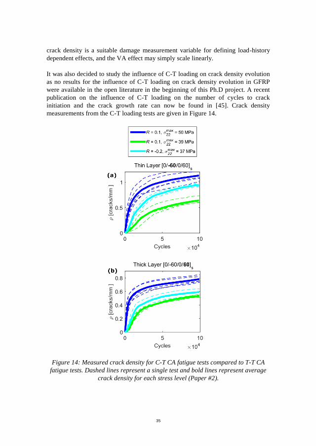
It was also decided to study the influence of C-T loading on crack density evolution
as no results for the influence of C-T loading on crack density evolution in GFRP
were available in the open literature in the beginning of this Ph.D project. A recent
publication on the influence of C-T loading on the number of cycles to crack
initiation and the crack growth rate can now be found in [45]. Crack density
measurements from the C-T loading tests are given in Figure 14.
Figure 14: Measured crack density for C-T CA fatigue tests compared to T-T CA
fatigue tests. Dashed lines represent a single test and bold lines represent average
crack density for each stress level (Paper #2).
CHARACTERIZATION AND MODELLING OF THE MULTIAXIAL FATIGUE RESPONSE OF GLASS FIBRE REINFORCED COMPOSITE MATERIALS
36
The 50 MPa CA T-T tests were subjected to the same load amplitude as the 37 MPa
C-T tests. Based on the results it was observed that T-T loading results in a higher
crack density evolution rate and apparent saturation value than C-T loading for the
same load amplitude. This is in agreement with results reported in [45].
3.3. ANALYSIS OF CRACK INITIATION AND CRACK GROWTH
The off-axis crack density evolution consists of initiation and steady-state crack
growth. ACC was extended to study these phenomena in more detail. The extension
consisted of a computer code, which could data mine the crack field test information
obtained from the ACC data acquisition method. The information extracted from the
crack field data was chosen to be initiation and crack growth rates for isolated off-
axis cracks. Isolated cracks refer to cracks, which have not felt the presence of other
cracks until it initiates and while it grows. When the tests are carried out in load
control, the stress at the location of the isolated cracks has not changed until the
crack initiates. Therefore, fatigue material properties can be directly derived from
data for initiation and crack growth of isolated cracks without imposing assumptions
on damage accumulation for varying load histories.
To determine when off-axis cracks could be considered as isolated a unit-cell Finite
Element (FE) model of the tested laminate was built. For a full description of the
model see (Paper #2). Using the unit-cell model, it was found, that off-axis cracks
could be considered isolated, as long as the location of crack initiation and the crack
front was distanced four times the layer thickness away from other cracks. Cycles to
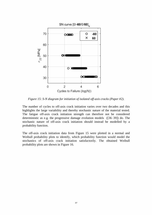
initiation of isolated cracks for the different CA stress levels are shown in Figure 15.
37
The number of cycles to off-axis crack initiation varies over two decades and this
highlights the large variability and thereby stochastic nature of the material tested.
The fatigue off-axis crack initiation strength can therefore not be considered
deterministic as e.g. the progressive damage evolution models ([36–39]) do. The
stochastic nature of off-axis crack initiation should instead be modelled by a
probability function.
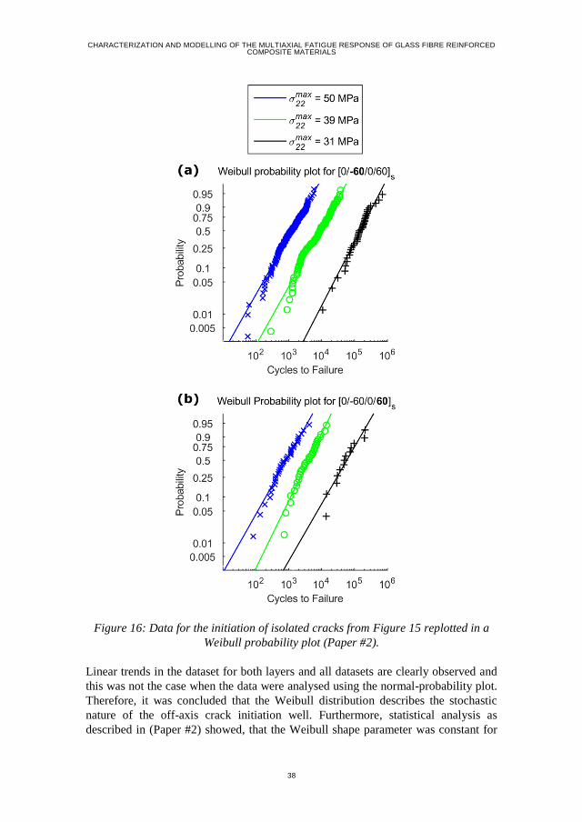
The off-axis crack initiation data from Figure 15 were plotted in a normal and
Weibull probability plots to identify, which probability function would model the
stochastics of off-axis crack initiation satisfactorily. The obtained Weibull
probability plots are shown in Figure 16.
Figure 15: S-N diagram for initiation of isolated off-axis cracks (Paper #2).
CHARACTERIZATION AND MODELLING OF THE MULTIAXIAL FATIGUE RESPONSE OF GLASS FIBRE REINFORCED COMPOSITE MATERIALS
38
Figure 16: Data for the initiation of isolated cracks from Figure 15 replotted in a
Weibull probability plot (Paper #2).
Linear trends in the dataset for both layers and all datasets are clearly observed and
this was not the case when the data were analysed using the normal-probability plot.
Therefore, it was concluded that the Weibull distribution describes the stochastic
nature of the off-axis crack initiation well. Furthermore, statistical analysis as
described in (Paper #2) showed, that the Weibull shape parameter was constant for
39
all tested stress levels and for both layers. The scale parameter was found to depend
on the stress level, and this relation could be modelled by the classical S-N power
law relationship given by:
𝑆 = 𝑆0𝑁𝑘 (1)
where S is the stress level (in this case chosen as 𝜎22𝑚𝑎𝑥), N is the number of cycles to
failure and 𝑆0 and k are empirical constants determined by fitting the S-N power law
to experimental data. As described in (Paper #2), this means that it is possible to
model the crack initiation process by a Weibull cumulative distribution function
given as:
𝑃𝑠(𝑥, 𝑆) = 1 − exp
(
−
[
𝑥
(𝑆𝑆0
)1/𝑘
] 𝛽
)
(2)
where 𝛽 is the Weibull shape parameter and 𝑥 is a stochastic variable with the unit
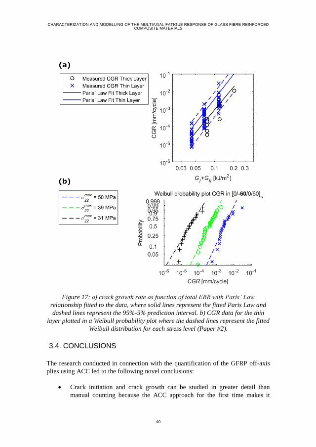
of number of cycles. The measured crack growth rates of isolated off-axis cracks
obtained from the data mining are plotted in Figure 17 as function of the calculated
Energy Release Rate (ERR).
Based on the results it is clear that the CGR increases with increasing ERR. This
relationship is commonly referred to as the Paris’ Law relationship and is given as
𝐶𝐺𝑅 = 𝐷 ∙ 𝐺𝑡𝑜𝑡𝑛 (3)
where 𝐺𝑡𝑜𝑡 is the total ERR and D and n are empirical constants determined by
fitting the Paris Law’ to the experimental data. A large variance in the data is
observed, and the magnitude of the variance is seen to be approximately the same as
found in [46]. The observed variance indicates that a single Paris’ Law relationship
is not sufficient to describe the physics of crack propagation. Therefore, the
measured Crack Growth Rates (CGR) were normalised using the fitted Paris Law
and the normalised data was analysed using normal and Weibull probability plots.
Based on this analysis it was found that the Weibull cumulative distribution function
given by
𝑃𝑐(𝐶𝐺𝑅, 𝐺𝑡𝑜𝑡) = 1 − exp(− [
𝐶𝐺𝑅
𝐷 ∙ 𝐺𝑡𝑜𝑡𝑛]
𝛽𝑐
) (4)
where 𝛽𝑐 is the Weibull shape parameter, was suitable for modelling the stochastic
nature of CGR. Furthermore, it was found that the Weibull shape parameter (𝛽𝑐)
was independent of the magnitude of the energy release rate.
CHARACTERIZATION AND MODELLING OF THE MULTIAXIAL FATIGUE RESPONSE OF GLASS FIBRE REINFORCED COMPOSITE MATERIALS
40
3.4. CONCLUSIONS
The research conducted in connection with the quantification of the GFRP off-axis
plies using ACC led to the following novel conclusions:
Crack initiation and crack growth can be studied in greater detail than
manual counting because the ACC approach for the first time makes it
Figure 17: a) crack growth rate as function of total ERR with Paris’ Law
relationship fitted to the data, where solid lines represent the fitted Paris Law and
dashed lines represent the 95%-5% prediction interval. b) CGR data for the thin
layer plotted in a Weibull probability plot where the dashed lines represent the fitted
Weibull distribution for each stress level (Paper #2).
41
feasible to detect and measure the crack evolution process throughout the
entire fatigue test with sufficient temporal resolution (Paper #2).
The crack density is a suitable damage measure for variable amplitude
block loading, and T-T loading results in a higher crack density evolution
rate and apparent saturation value than C-T loading for the same load
amplitude (Paper #2).
It is possible to efficiently derive the classical S-N relationship and Paris’
Law like curves from the data obtained using the ACC approach and by
fully accounting for crack interaction, so the nature and magnitude of the
stress is established at every measurement and material point throughout
the fatigue test providing an enhanced understanding of the causes of the
damage progression (Paper #2).
The Weibull distribution represents effectively the stochastic nature of
isolated off-axis crack initiation and crack growth rate, and the Weibull
parameters are derived directly, i.e. without resorting to inverse techniques,
using ACC due to the data rich nature of the measurement method (Paper
#2).
The shape parameter of the Weibull distribution is independent of the
applied stress and does not vary with ply thicknesses (Paper #2).
CHARACTERIZATION AND MODELLING OF THE MULTIAXIAL FATIGUE RESPONSE OF GLASS FIBRE REINFORCED COMPOSITE MATERIALS
42
CHAPTER 4. MICRO-MECHANICAL
MODELS FOR PREDICTING STIFFNESS
DEGRADATION
As shown in Chapter 3, the off-axis crack density evolution explains the stiffness
degradation observed during the fatigue tests. The stiffness of the MD laminate
decreases as the off-axis crack density increases. Furthermore, off-axis cracks result
in stress redistribution in the damaged MD laminate, where stress in adjacent layers
is increased and the stress in the damaged layer is decreased. The decrease of the
stress in the damaged layers results in a shielding effect. The shielding effect
impedes crack initiation and lowers the crack growth rate of propagating cracks. It is
therefore important to both predict the stiffness degradation of the laminate as this
can be used to assess if the overall structural requirements are met by the damaged
laminate and to accurately predict the shielding effect as this is needed to describe
the off-axis crack evolution process based on the derived fatigue evolution
parameters.
Correlating the off-axis crack density with the stiffness degradation of an arbitrary
MD laminate is essentially a 3D solid mechanics problem. In most cases, it is
difficult or impossible to obtain an accurate analytical solution for this. The problem
could be solved using FE based techniques but such an approach was disregarded as
it is computationally heavy. Several analytical models for predicting the stiffness
degradation based on the off-axis crack density have been proposed in the open
literature e.g. [14,47–50]. The proposed models use simplifying assumptions to
obtain predictions for the stiffness degradation of the laminate. Based on a literature
review of available models it was decided to use the well-developed GLOB-LOC
model [14,51–53]. The GLOB-LOC model was chosen because:
Applies to arbitrary laminates
Provide results for Crack Opening Displacement (COD) and Crack Sliding
Displacement (CSD), which are used to compute the Mode I and Mode II
ERRs according to the method described in [20]
Accounting for crack interaction in terms of COD as presented in [52]
Fast to compute
Extendable framework as utilised in Paper #4, where the following tools
have been developed and implemented in the model:
- Accounting for crack interaction in terms of CSD
- Recovery of the transverse normal stress and shear stress field between
off-axis cracks
43
4.1. GLOB-LOC
The GLOB-LOC model belongs to the class of Crack Faces Displacement (CFD)
models [48]. These types of models use the micro-mechanical theorem, which states
that the volume average linear strains for a given layer are equal to the boundary-
averaged linear strains:
𝐸𝑖𝑗 =
1
𝑉∫
1
2(𝑢𝑖𝑛𝑗 + 𝑢𝑗𝑛𝑖)𝑑𝑆
𝑆
(5)
where 𝐸𝑖𝑗 is the volume average strain tensor, V is the volume, S is the surface and
𝑢𝑖 is the displacement vector at the surface defined by the normal vector 𝑛𝑗. In the
following a plane stress state will be assumed and the influence of out-of-plane
transverse shear will be neglected. Therefore, only in plane strains are considered in
relation to (5). The boundary-averaged in-plane strains include both the macroscopic
laminate boundary surface and the internal off-axis crack surfaces. The boundary-
averaged strains therefore consist of two parts and the equality from (5) for the k’th
laminate layer can then be written as:
{𝜖11
𝜖22
��12
}
𝑘
= {
𝜖11
𝜖22
𝛾12
}
𝐿𝐴𝑀
+ {
𝛽11
𝛽22
2𝛽12
}
𝑘
(6)
where 𝜖��𝛽 is the volume average strains, 𝜖𝛼𝛽 denotes the strains at the laminate
boundary and 𝛽𝛼𝛽 denotes the Vakulenko-Kachanov tensor defined as:
𝛽𝛼𝛽 =
1
𝑉∫
1
2(𝑢𝛼𝑛𝛽 + 𝑢𝛽𝑛𝛼)𝑑𝑆
𝑠𝑐
(7)
where 𝑠𝑐 is the surface of internal crack faces. The volume average strains in (6) can
then be determined using volume averaged equilibrium conditions and the
constitutive relations for the material. The problem of determining the stiffness of
the damaged laminate then becomes a problem of determining 𝛽𝛼𝛽 for each layer
which is equivalent to determining the displacements of internal crack faces.
Figure 18 shows the geometry of a Representative Volume Element (RVE) with
global coordinate system and the local material coordinate system for the cracked
middle layer.
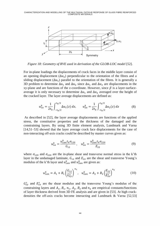
CHARACTERIZATION AND MODELLING OF THE MULTIAXIAL FATIGUE RESPONSE OF GLASS FIBRE REINFORCED COMPOSITE MATERIALS
44
For in-plane loadings the displacements of crack faces in the middle layer consist of
an opening displacement (Δ𝑢2) perpendicular to the orientation of the fibres and a
sliding displacement (Δ𝑢1) parallel to the orientation of the fibres. It is generally a
3D problem to determine Δ𝑢1 and Δ𝑢2 since Δ𝑢1 and Δ𝑢2 are displacements in the
xy-plane and are functions of the z-coordinate. However, since 𝛽 is a layer-surface-
average it is only necessary to determine Δ𝑢1 and Δ𝑢2 averaged over the height of
the cracked layer. The layer average displacements are defined as:
𝑢1𝑎
𝑘 =1
2𝑡𝑘∫ Δ𝑢1(𝑧)
𝑡𝑘/2
−𝑡𝑘/2
𝑑𝑧, 𝑢2𝑎𝑘 =
1
2𝑡𝑘∫ Δ𝑢2(𝑧)
𝑡𝑘/2
−𝑡𝑘/2
𝑑𝑧 (8)
As described in [52], the layer average displacements are functions of the applied
stress, the constitutive properties and the thickness of the damaged and the
constraining layers. By using 3D finite element analysis, Lundmark and Varna
[14,51–53] showed that the layer average crack face displacements for the case of
non-interacting off-axis cracks could be described by master curves given as:
𝑢1𝑎
𝑘 =𝑢1𝑎𝑛
𝑘 𝑡𝑘𝜎120
𝐺12
, 𝑢2𝑎𝑘 =
𝑢2𝑎𝑛𝑘 𝑡𝑘𝜎220
𝐸22
(9)
where 𝜎120 and 𝜎220 are the in-plane shear and transverse normal stress in the k’th
layer in the undamaged laminate, 𝐺12 and 𝐸22 are the shear and transverse Young’s
modulus of the k’th layer and 𝑢1𝑎𝑛𝑘 and 𝑢2𝑎𝑛
𝑘 are given as:
𝑢1𝑎𝑛
0 = 𝐴1 + 𝐵1 (𝐺12
𝐺𝑥𝑦𝑠
)
𝑛1
, 𝑢2𝑎𝑛0 = 𝐴2 + 𝐵2 (
𝐸22
𝐸𝑥𝑥𝑠
)𝑛2
(10)
𝐺𝑥𝑦𝑠 and 𝐸𝑥𝑥
𝑠 are the shear modulus and the transverse Young’s modulus of the
constraining layers and 𝐴1, 𝐵1, 𝑛1, 𝐴2, 𝐵2 and 𝑛2 are empirical constants/functions
of layer thickness derived from 3D FE analysis and are given in [53]. At high crack-
densities the off-axis cracks become interacting and Lundmark & Varna [52,53]
Figure 18: Geometry of RVE used in derivation of the GLOB-LOC model [52].
45
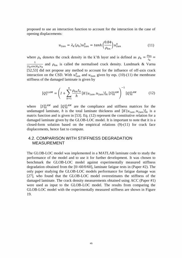
proposed to use an interaction function to account for the interaction in the case of
opening displacements:
𝑢2𝑎𝑛 = 𝜆𝑘(𝜌𝑘)𝑢2𝑎𝑛
0 = 𝑡𝑎𝑛ℎ (0.84
𝜌𝑘𝑛
)𝑢2𝑎𝑛0 (11)
where 𝜌𝑘 denotes the crack density in the k’th layer and is defined as 𝜌𝑘 =𝜌𝑘𝑛
𝑡𝑘=
1
2𝑙𝑘𝑠𝑖𝑛(𝜃𝑘)𝑡𝑘 and 𝜌𝑘𝑛 is called the normalised crack density. Lundmark & Varna
[52,53] did not propose any method to account for the influence of off-axis crack
interaction on the CSD. With 𝑢1𝑎𝑛0 and 𝑢2𝑎𝑛 given by eqs. (10)-(11) the membrane
stiffness of the damaged laminate is given by
[𝑄]𝐿𝐴𝑀 = (𝐼 + ∑𝜌𝑘𝑛𝑡𝑘
ℎ[𝐾(𝑢1𝑎𝑛, 𝑢2𝑎𝑛)]𝑘
𝑛
𝑘=1
[𝑆]0𝐿𝐴𝑀)
−1
[𝑄]0𝐿𝐴𝑀 (12)
where [𝑆]0𝐿𝐴𝑀 and [𝑄]0
𝐿𝐴𝑀 are the compliance and stiffness matrices for the
undamaged laminate, h is the total laminate thickness and [𝐾(𝑢1𝑎𝑛 , 𝑢2𝑎𝑛)]𝑘 is a
matrix function and is given in [53]. Eq. (12) represent the constitutive relation for a
damaged laminate given by the GLOB-LOC model. It is important to note that it is a
closed-form solution based on the empirical relations (9)-(11) for crack face
displacements, hence fast to compute.
4.2. COMPARISON WITH STIFFNESS DEGRADATION MEASUREMENT
The GLOB-LOC model was implemented in a MATLAB laminate code to study the
performance of the model and to use it for further development. It was chosen to
benchmark the GLOB-LOC model against experimentally measured stiffness
degradation obtained from the [0/-60/0/60]s laminate fatigue tests in (Paper #2). The
only paper studying the GLOB-LOC models performance for fatigue damage was
[27], who found that the GLOB-LOC model overestimates the stiffness of the
damaged laminate. The crack density measurements obtained using ACC (Paper #1)
were used as input to the GLOB-LOC model. The results from comparing the
GLOB-LOC model with the experimentally measured stiffness are shown in Figure
19.
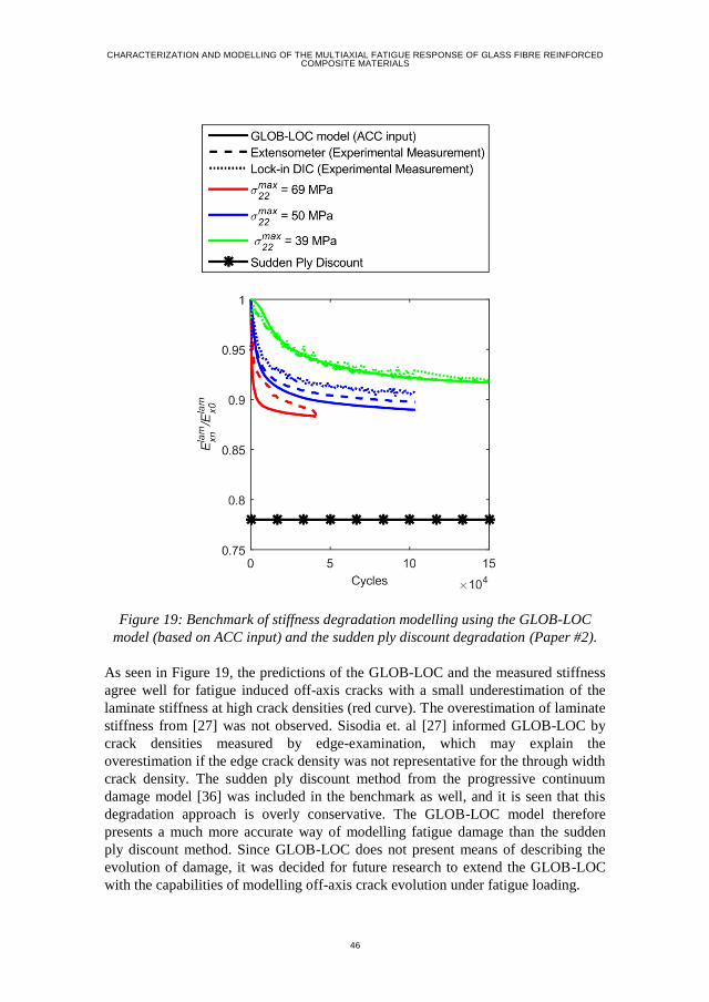
CHARACTERIZATION AND MODELLING OF THE MULTIAXIAL FATIGUE RESPONSE OF GLASS FIBRE REINFORCED COMPOSITE MATERIALS
46
Figure 19: Benchmark of stiffness degradation modelling using the GLOB-LOC
model (based on ACC input) and the sudden ply discount degradation (Paper #2).
As seen in Figure 19, the predictions of the GLOB-LOC and the measured stiffness
agree well for fatigue induced off-axis cracks with a small underestimation of the
laminate stiffness at high crack densities (red curve). The overestimation of laminate
stiffness from [27] was not observed. Sisodia et. al [27] informed GLOB-LOC by
crack densities measured by edge-examination, which may explain the
overestimation if the edge crack density was not representative for the through width
crack density. The sudden ply discount method from the progressive continuum
damage model [36] was included in the benchmark as well, and it is seen that this
degradation approach is overly conservative. The GLOB-LOC model therefore
presents a much more accurate way of modelling fatigue damage than the sudden
ply discount method. Since GLOB-LOC does not present means of describing the
evolution of damage, it was decided for future research to extend the GLOB-LOC
with the capabilities of modelling off-axis crack evolution under fatigue loading.
47
4.3. EXTENDING GLOB-LOC
Off-axis crack evolution in composite laminates is a multi-scale and hierarchical
process, involving several length scales [54]. Off-axis crack initiation results from
damage accumulation in the matrix material at the micro-scale, i.e. at the length
scale of the inter-fibre spacing [54]. Off-axis crack propagation is controlled by
micro-cracks in the matrix material ahead of the off-axis crack tip (Chapter 5 &
Paper #3). The damage evolution rate for off-axis crack initiation and propagation is
described by non-linear functions of the local stress state at the origin of damage (S-
N and Paris’ Law like relationships). In order to predict and model off-axis crack
initiation and propagation it is therefore necessary to accurately compute the stress
state at the location of the damage development.
GLOB-LOC in the form provided in [14,51–53] has some limitations, which make it
difficult to use for describing off-axis crack evolution. As GLOB-LOC is based on
volume and boundary averaging it is only possible to obtain stress/strain information
averaged over the entire volume of each layer. The stress in a damaged layer varies
between a stress free condition on the crack faces to a stress state equivalent to the
one in the undamaged laminate, if the material point under consideration is
distanced sufficiently far from off-axis cracks. Since the SN-relationship and the
Paris’ Law like relationship are non-linear it is not correct to use volume average
stresses/strains. Further on, the GLOB-LOC model does not provide a way to
account for CSD interaction at high intralaminar crack densities. CSD interaction is
important to take into consideration when accurately determining the local
multiaxial stress state and the local mixed-mode loading condition ([54], Paper #3).
It was therefore decided to extend GLOB-LOC in the present project with a way to
model CSD interaction and to obtain the variations in the stress field within a
damaged layer.
Parametric 3D FE analysis of a cross-ply laminate was carried out for the CSD
interaction. The COD and the CSD as function of the crack density were derived
from the model for different constraining layer thicknesses. The FE model used to
study the COD interaction was similar to the model given in [52] and the derived
results are given in Figure 20(a). The results from Figure 20(a) agree with the results
from [52], which thereby validate the FE-model developed in the current project.
The same model, but with CSD boundary Conditions as described in (Paper #4) was
then used to determine the CSD interaction function. The derived CSD as function
of crack density for different constraining layer thicknesses are shown in Figure
20(b). Based on these results it was found that the CSD when crack interaction was
presented can be modelled by:
𝑢1𝑎𝑛 = 𝜆𝑘(𝜌𝑘)𝑢1𝑎𝑛
0 = 𝑡𝑎𝑛ℎ (1.3
𝜌𝑘𝑛
) 𝑢1𝑎𝑛0 𝑓𝑜𝑟 𝜎22 > 0 (13)
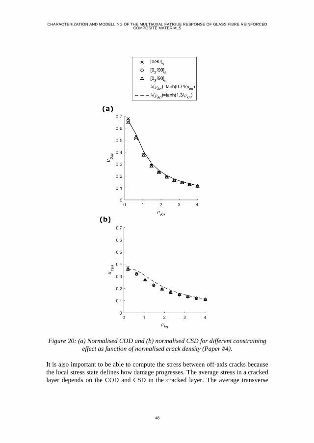
CHARACTERIZATION AND MODELLING OF THE MULTIAXIAL FATIGUE RESPONSE OF GLASS FIBRE REINFORCED COMPOSITE MATERIALS
48
It is also important to be able to compute the stress between off-axis cracks because
the local stress state defines how damage progresses. The average stress in a cracked
layer depends on the COD and CSD in the cracked layer. The average transverse
Figure 20: (a) Normalised COD and (b) normalised CSD for different constraining
effect as function of normalised crack density (Paper #4).
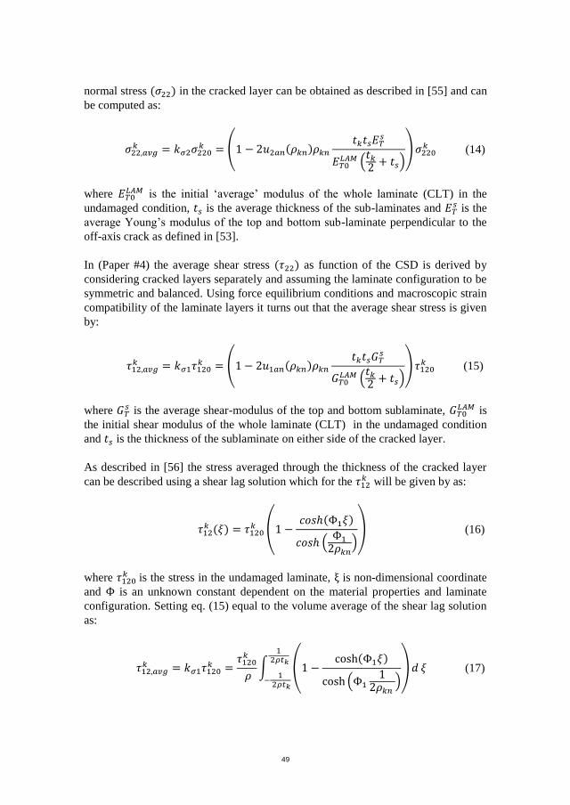
49
normal stress (𝜎22) in the cracked layer can be obtained as described in [55] and can
be computed as:
𝜎22,𝑎𝑣𝑔𝑘 = 𝑘𝜎2𝜎220
𝑘 = (1 − 2𝑢2𝑎𝑛(𝜌𝑘𝑛)𝜌𝑘𝑛
𝑡𝑘𝑡𝑠𝐸𝑇𝑠
𝐸𝑇0𝐿𝐴𝑀 (
𝑡𝑘2
+ 𝑡𝑠))𝜎220
𝑘 (14)
where 𝐸𝑇0𝐿𝐴𝑀 is the initial ‘average’ modulus of the whole laminate (CLT) in the
undamaged condition, 𝑡𝑠 is the average thickness of the sub-laminates and 𝐸𝑇𝑠 is the
average Young’s modulus of the top and bottom sub-laminate perpendicular to the
off-axis crack as defined in [53].
In (Paper #4) the average shear stress (𝜏22) as function of the CSD is derived by
considering cracked layers separately and assuming the laminate configuration to be
symmetric and balanced. Using force equilibrium conditions and macroscopic strain
compatibility of the laminate layers it turns out that the average shear stress is given
by:
𝜏12,𝑎𝑣𝑔𝑘 = 𝑘𝜎1𝜏120
𝑘 = (1 − 2𝑢1𝑎𝑛(𝜌𝑘𝑛)𝜌𝑘𝑛
𝑡𝑘𝑡𝑠𝐺𝑇𝑠
𝐺𝑇0𝐿𝐴𝑀 (
𝑡𝑘2
+ 𝑡𝑠)) 𝜏120
𝑘 (15)
where 𝐺𝑇𝑠 is the average shear-modulus of the top and bottom sublaminate, 𝐺𝑇0
𝐿𝐴𝑀 is
the initial shear modulus of the whole laminate (CLT) in the undamaged condition
and 𝑡𝑠 is the thickness of the sublaminate on either side of the cracked layer.
As described in [56] the stress averaged through the thickness of the cracked layer
can be described using a shear lag solution which for the 𝜏12𝑘 will be given by as:
𝜏12𝑘 (𝜉) = 𝜏120
𝑘 (1 −𝑐𝑜𝑠ℎ(Φ1𝜉)
𝑐𝑜𝑠ℎ (Φ1
2𝜌𝑘𝑛)) (16)
where 𝜏120𝑘 is the stress in the undamaged laminate, ξ is non-dimensional coordinate
and Φ is an unknown constant dependent on the material properties and laminate
configuration. Setting eq. (15) equal to the volume average of the shear lag solution
as:
𝜏12,𝑎𝑣𝑔𝑘 = 𝑘𝜎1𝜏120
𝑘 =𝜏120
𝑘
𝜌∫ (1 −
cosh(Φ1𝜉)
cosh (Φ11
2𝜌𝑘𝑛 ))𝑑
1 2𝜌𝑡𝑘
−1
2𝜌𝑡𝑘
𝜉 (17)
CHARACTERIZATION AND MODELLING OF THE MULTIAXIAL FATIGUE RESPONSE OF GLASS FIBRE REINFORCED COMPOSITE MATERIALS
50
then Φ1 is the only unknown parameter and can hence be determined. To validate
this approach the stresses were computed using the now modified GLOB-LOC
model and derived using the 3D FE unit-cell model as described in (Paper #4). The
results obtained from both models are shown in Figure 21.
It is clearly seen that the stress field is accurately recovered, which is needed to
compute the local damage evolution rate at different locations within the laminate
where off-axis cracks might initiate and propagate. Furthermore, it should be noted
that the results presented in this section also serve as a validation of the
implementation of the modified GLOB-LOC model.
4.4. CONCLUSIONS
The research conducted in connection with modelling the stiffness degradation using
the GLOB-LOC model led to the following conclusions:
The GLOB-LOC model slightly under predicts the stiffness of the degraded
laminate whereas the sudden ply discount policy under-predicts the
stiffness by a large margin indicating that the sudden ply discount approach
is not suitable for modelling fatigue damage (Paper #2).
The effect of crack interaction on the CSD at high intralaminar crack
densities can be accounted for by the interaction function in eq. (13) for
GFRP laminates with different constraining effects when no compressive
stresses are acting on the crack faces.
The GLOB-LOC model has been extended such that the varying stress field
within the damaged layer can be recovered from the volume average
properties obtained from the original GLOB-LOC model.
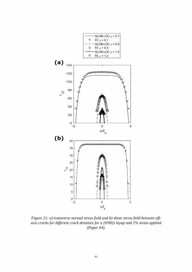
51
Figure 21: a) transverse normal stress field and b) shear stress field between off-
axis cracks for different crack densities for a [0/90]s layup and 1% strain applied
(Paper #4).
CHARACTERIZATION AND MODELLING OF THE MULTIAXIAL FATIGUE RESPONSE OF GLASS FIBRE REINFORCED COMPOSITE MATERIALS
52
CHAPTER 5. A MIXED-MODE
PROPAGATION MODEL FOR OFF-AXIS
CRACKS (PAPER #3)
Based on the successful validation and extension of GLOB-LOC, it was decided to
develop an off-axis crack damage evolution model using only the information
provided by the GLOB-LOC model. Recently, Carraro and Quaresimin [57]
developed a physically based multiaxial evolution model for off-axis crack initiation
based on damage modes observed on the micro-scale. Two different damage modes
were observed at the micro-scale, where one damage mode was a micro crack
parallel to the fibres and close to the interface and the other damage mode was a
shear cusp crack. Carraro and Quaresimin [57] proposed that the Local Hydrostatic
Stress (LHS) is responsible for the micro cracks parallel to the fibres, and the Local
Maximum Principal Stress (LMPS) is responsible for the shear cusp cracks. The
damage evolution rate as function of the stress level is based on an SN relationship
for each damage mode. This means that in order to use the model, the composite
material has to be fatigue tested in two different multiaxial stress conditions where
each damage mode is activated. Hence, the model requires a very limited
experimental campaign to characterise the material and it is physically based such
that it is generally applicable to different multiaxial stress states. It was decided to
use the model from [57] to predict and model the initiation of off-axis cracks, since
the model can be evaluated using information obtained from the GLOB-LOC model.
For the propagation part of the evolution process, the open literature was searched
for physically based models capable of predicting the CGR. The CGR depends on
the magnitude of the applied load, the geometry of the crack and the mode-mixity
[58]. The literature survey is given in (Paper #3), and from this survey it is clear that
no physical based models suitable for describing off-axis crack propagation under
mixed-mode loading conditions were available in the open literature. Prof. Marino
Quaresimin and his research group at the University of Padova were also searching
for a similar model for their research activities and therefore it was decided to
develop a model as a joint effort. The requirements for the model were defined to
be:
Physically based such that it describes the actual damage modes observed
in experiments.
Computationally efficient, meaning that it should be possible to evaluate
the model using only information provided by micro-mechanical models
(as e.g. the GLOB-LOC model).
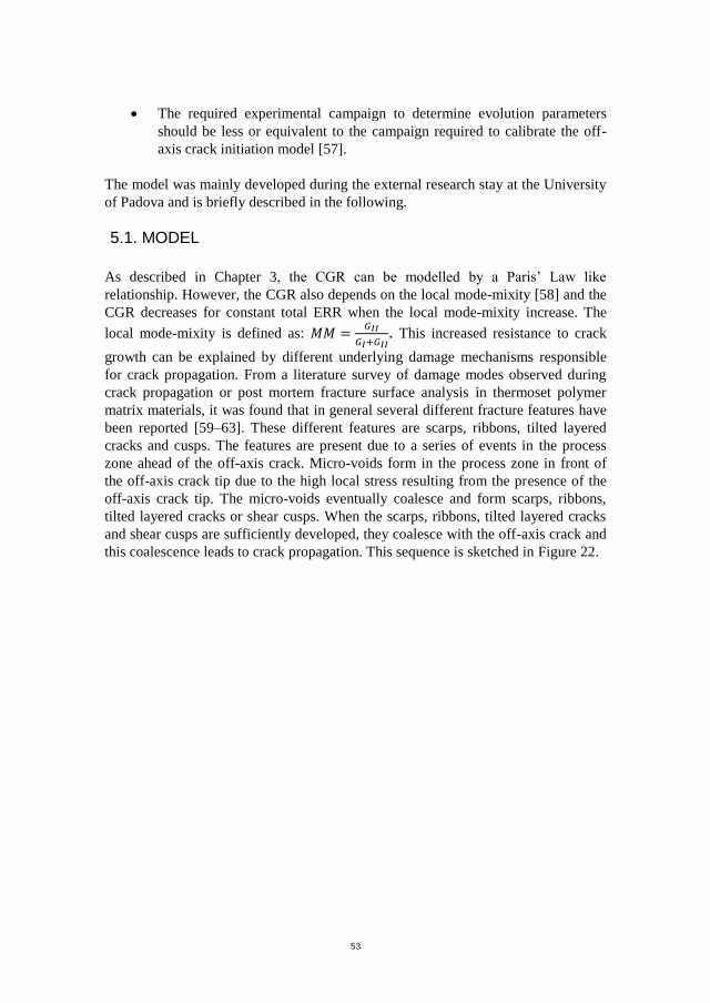
53
The required experimental campaign to determine evolution parameters
should be less or equivalent to the campaign required to calibrate the off-
axis crack initiation model [57].
The model was mainly developed during the external research stay at the University
of Padova and is briefly described in the following.
5.1. MODEL
As described in Chapter 3, the CGR can be modelled by a Paris’ Law like
relationship. However, the CGR also depends on the local mode-mixity [58] and the
CGR decreases for constant total ERR when the local mode-mixity increase. The
local mode-mixity is defined as: 𝑀𝑀 =𝐺𝐼𝐼
𝐺𝐼+𝐺𝐼𝐼. This increased resistance to crack
growth can be explained by different underlying damage mechanisms responsible
for crack propagation. From a literature survey of damage modes observed during
crack propagation or post mortem fracture surface analysis in thermoset polymer
matrix materials, it was found that in general several different fracture features have
been reported [59–63]. These different features are scarps, ribbons, tilted layered
cracks and cusps. The features are present due to a series of events in the process
zone ahead of the off-axis crack. Micro-voids form in the process zone in front of
the off-axis crack tip due to the high local stress resulting from the presence of the
off-axis crack tip. The micro-voids eventually coalesce and form scarps, ribbons,
tilted layered cracks or shear cusps. When the scarps, ribbons, tilted layered cracks
and shear cusps are sufficiently developed, they coalesce with the off-axis crack and
this coalescence leads to crack propagation. This sequence is sketched in Figure 22.
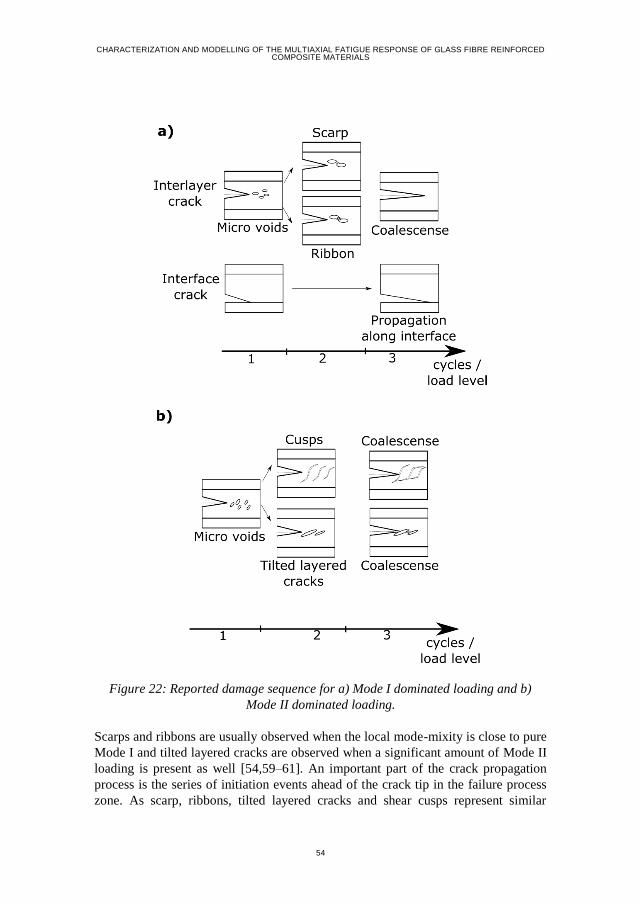
CHARACTERIZATION AND MODELLING OF THE MULTIAXIAL FATIGUE RESPONSE OF GLASS FIBRE REINFORCED COMPOSITE MATERIALS
54
Figure 22: Reported damage sequence for a) Mode I dominated loading and b)
Mode II dominated loading.
Scarps and ribbons are usually observed when the local mode-mixity is close to pure
Mode I and tilted layered cracks are observed when a significant amount of Mode II
loading is present as well [54,59–61]. An important part of the crack propagation
process is the series of initiation events ahead of the crack tip in the failure process
zone. As scarp, ribbons, tilted layered cracks and shear cusps represent similar
55
features as observed for off-axis crack initiation [57] and their occurrence is a result
of the local stress state in front of the crack, it was decided to use the magnitude of
the LHS and LMPS in the matrix in front of the off-axis as measures for describing
the off-axis CGR.
However, to compute the LHS and LMPS in the process zone represent a 3D multi-
scale problem, since the LHS and LMPS depends on the crack geometry, the
constraining effect of adjacent layers, the local mode-mixity and the micro-scale
geometry. Therefore, a part of (Paper #3) represents a multi-scale approach to obtain
the LHS and LMPS in the process zone based on information obtained from micro-
mechanical models. It is not known at which distance the off-axis cracks initiates,
and therefore the magnitude of LHS and LMPS controlling crack propagation are
formulated in terms of equivalent ERRs derived from the stress intensity factors
(SIFs) for the off-axis crack (Paper #3). The proposed equivalent ERRs are:
𝐺𝑒𝑞𝐿𝐻𝑆 = 𝐺𝐼= 𝑀𝑀 ⋅ 𝐺𝑡𝑜𝑡 (18)
𝐺𝑒𝑞𝐿𝑀𝑃𝑆 = (√𝑀𝑀 + √1 − 𝑀𝑀)
2⋅ (𝐺𝐼 + 𝐺𝐼𝐼)
= (√𝑀𝑀 + √1 − 𝑀𝑀)2⋅ (𝐺𝑡𝑜𝑡)
(19)
where 𝐺𝑡𝑜𝑡 and 𝑀𝑀 can be directly obtained from the GLOB-LOC model. The
equivalent ERRs from Eqs. (18) and (19) are used to derive two Paris’ Law
relationships for the tested material. The Paris’ Law relationships are used to predict
the CGRs for any local mode-mixity and failure mode. The Paris’ Law predicting
the highest CGR is used to predict the crack density. The transition between the
derived Paris’ Laws has been found to be in good agreement with the transition of
the observed damage modes on the microscopic scale (Paper #3), indicating that the
model is in agreement with the physical damage evolution. Further on, it should be
noted that the model does not require extensive testing to derive evolution
parameters, since the two required Paris’ Law curves can be derived from the same
tests used to derive the SN-curves required for the initiation model from [57].
5.2. RESULTS
To illustrate the general applicability of the physically based model several data sets
from the literature were analysed using Eqs. (18) and (19). (Paper #3) presents the
results from using the model on off-axis crack propagation data from [58] and data
for delamination in 0°/0° layer interfaces from [64,65]. The results from using the
model on off-axis crack propagation data from [58] are also shown in Figure 23,
where the crack propagation data is plotted in terms of 𝐺𝑡𝑜𝑡, 𝐺𝑒𝑞𝐿𝐻𝑆 and 𝐺𝑒𝑞
𝐿𝑀𝑃𝑆 and
Paris’ Law like relationships have been fitted to the data for Mode I (𝑀𝑀 =[0; 0.26]) and Mode II (𝑀𝑀 =]0.26; 1]) dominated propagation.
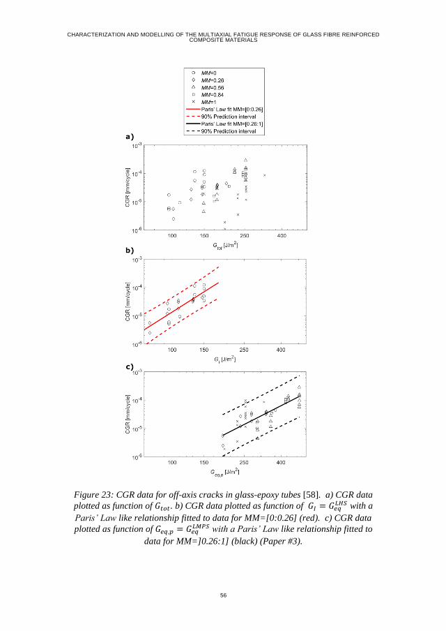
CHARACTERIZATION AND MODELLING OF THE MULTIAXIAL FATIGUE RESPONSE OF GLASS FIBRE REINFORCED COMPOSITE MATERIALS
56
Figure 23: CGR data for off-axis cracks in glass-epoxy tubes [58]. a) CGR data
plotted as function of 𝐺𝑡𝑜𝑡. b) CGR data plotted as function of 𝐺𝐼 = 𝐺𝑒𝑞𝐿𝐻𝑆 with a
Paris’ Law like relationship fitted to data for MM=[0:0.26] (red). c) CGR data
plotted as function of 𝐺𝑒𝑞,𝑝 = 𝐺𝑒𝑞𝐿𝑀𝑃𝑆 with a Paris’ Law like relationship fitted to
data for MM=]0.26:1] (black) (Paper #3).
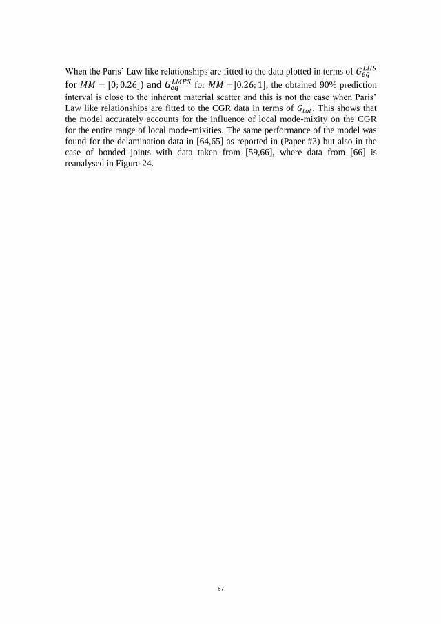
57
When the Paris’ Law like relationships are fitted to the data plotted in terms of 𝐺𝑒𝑞𝐿𝐻𝑆
for 𝑀𝑀 = [0; 0.26]) and 𝐺𝑒𝑞𝐿𝑀𝑃𝑆 for 𝑀𝑀 =]0.26; 1], the obtained 90% prediction
interval is close to the inherent material scatter and this is not the case when Paris’
Law like relationships are fitted to the CGR data in terms of 𝐺𝑡𝑜𝑡. This shows that
the model accurately accounts for the influence of local mode-mixity on the CGR
for the entire range of local mode-mixities. The same performance of the model was
found for the delamination data in [64,65] as reported in (Paper #3) but also in the
case of bonded joints with data taken from [59,66], where data from [66] is
reanalysed in Figure 24.
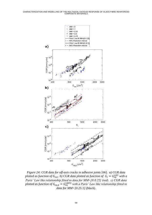
CHARACTERIZATION AND MODELLING OF THE MULTIAXIAL FATIGUE RESPONSE OF GLASS FIBRE REINFORCED COMPOSITE MATERIALS
58
Figure 24: CGR data for off-axis cracks in adhesive joints [66]. a) CGR data
plotted as function of 𝐺𝑡𝑜𝑡. b) CGR data plotted as function of 𝐺𝐼 = 𝐺𝑒𝑞𝐿𝐻𝑆 with a
Paris’ Law like relationship fitted to data for MM=[0:0.25] (red). c) CGR data
plotted as function of 𝐺𝑒𝑞,𝑝 = 𝐺𝑒𝑞𝐿𝑀𝑃𝑆 with a Paris’ Law like relationship fitted to
data for MM=]0.25:1] (black).
59
5.3. ACCOUNTING FOR THE STRESS RATIO INFLUENCE
Since crack propagation is a series of damage modes resembling those of initiation,
it is expected that changing the stress ratio will have the same influence on CGR as
shown for initiation. To model the influence of load ratio on the number of cycles to
off-axis crack initiation [67] proposed an empirical normalisation principle:
ψ =𝜎𝑎
𝜎𝑠 − 𝜎𝑚
=
1 − 𝑅2
𝜎𝑚𝑎𝑥
𝜎𝑠 −1 + 𝑅
2𝜎𝑚𝑎𝑥
=(1 − 𝑅)𝜎𝑚𝑎𝑥
2𝜎𝑠 − (1 + 𝑅)𝜎𝑚𝑎𝑥
(20)
where 𝜎𝑎 , 𝜎𝑚, 𝜎𝑚𝑎𝑥 and 𝜎𝑠 are the stress amplitude, the mean stress, the max stress
and the ultimate tensile strength, respectively, and the stress ratio is given by
𝑅 =𝜎𝑚𝑖𝑛
𝜎𝑚𝑎𝑥. In [68] it was demonstrated that if the stress measures used in Eq. (20)
were LHS and LMPS, it would collapse off-axis crack initiation for glass-epoxy
tubes from [45] into two master curves.
Assuming that a change in load ratio does not change the type of damage
mechanisms in the process zone of the off-axis crack, then Eq. (20) can be rewritten
in terms of 𝐾ℎ and 𝐾𝑝 (as defined in Paper #3). The modification of Eq. (20) is then
given as:
𝜑 =
𝐾𝑓𝑎 1
√2𝜋𝑟
𝐾𝑓𝑆 1
√2𝜋𝑟− 𝐾𝑓
𝑚 1
√2𝜋𝑟
=(1 − 𝑅𝑓)𝐾𝑓
𝑀𝑎𝑥
2𝐾𝑓𝑆 − (1 + 𝑅𝑓)𝐾𝑓
𝑀𝑎𝑥 (21)
where subscript f = h or p, 𝐾𝑓𝑆 is the equivalent SIF resulting in quasi static failure
and hence unstable crack growth and 𝑅𝑓 =𝐾𝑚𝑖𝑛
𝐾𝑚𝑎𝑥. Expressing Eq. (21) in terms of the
equivalent ERRs given in Eqs. (18)-(19) give:
φd =
(1 − 𝑅𝑐𝑑)√𝐺𝑚𝑎𝑥
𝑑
2√𝐺𝑞𝑑 − (1 + 𝑅𝑐
𝑑)√𝐺𝑚𝑎𝑥𝑑
(22)
where d=LHS or LMPS and 𝐺𝑚𝑎𝑥𝑑 is the maximum equivalent ERR for the active
damage mode that controls the crack propagation. The reference stress ratio
𝑅𝑐𝑑 =
√𝐺𝑚𝑖𝑛𝑑
√𝐺𝑚𝑎𝑥𝑑
for each unique damage mode d and 𝐺𝑞𝑑 is equivalent to the ERR
CHARACTERIZATION AND MODELLING OF THE MULTIAXIAL FATIGUE RESPONSE OF GLASS FIBRE REINFORCED COMPOSITE MATERIALS
60
required for unstable crack propagation for each damage mode. Relating 𝐺𝑞𝑑 directly
with the measured quasi-static ply strength is virtually impossible, since it would
require a precise knowledge about the initial conditions of the defect that initiates
the off-axis crack. Instead 𝐺𝑞𝑑 can be experimentally derived by defining the load at
which an off-axis crack with a length that gives a steady-state ERR starts to
propagate in an unstable manner. Data for e.g. 𝐺𝑞𝐿𝑀𝑃𝑆 is not available in [68], but the
static initiation strength of the material 𝜎𝑠𝐿𝑀𝑃𝑆 is provided. Assuming that increasing
the load in an undamaged laminate to 𝜎𝑠𝐿𝑀𝑃𝑆 leads to unstable crack propagation for
a crack length longer than the one required to reach the steady-state ERR, then
𝐺𝐶𝐺𝑅,𝑀𝑎𝑥𝐿𝑀𝑃𝑆 < 𝐺𝑞
𝐿𝑀𝑃𝑆 ≤ 𝐺𝑆,𝑀𝑎𝑥𝐿𝑀𝑃𝑆 (23)
where 𝐺𝐶𝐺𝑅,𝑀𝑎𝑥𝐿𝑀𝑃𝑆 is the maximum equivalent ERR where stable crack propagation is
observed and 𝐺𝑺,𝑀𝑎𝑥𝐿𝑀𝑃𝑆 is the maximum equivalent ERR at quasi-static crack initiation.
From the static strength reported in [68] 𝐺𝑺,𝑀𝑎𝑥𝐿𝑀𝑃𝑆 can be derived to 𝐺𝑺,𝑀𝑎𝑥
𝐿𝑀𝑃𝑆 =
1.37 𝑘𝐽/𝑚2. The highest value of 𝐺𝐶𝐺𝑅,𝑀𝑎𝑥𝐿𝑀𝑃𝑆 for the same material is found in tests of
the flat [0/502/0/-502]s laminate in [20] and from these data can be computed to
𝐺𝐶𝐺𝑅,𝑀𝑎𝑥𝐿𝑀𝑃𝑆 = 0.98 𝑘𝐽/𝑚2.
In [45] the same material as tested in [68] and [20] has been tested at different stress
ratios. The CGR data obtained from [45] for two different stress ratios is plotted in
Figure 25(a). The same data is plotted in Figure 25(b) and Figure 25(c) in terms of
φ𝐿𝑀𝑃𝑆 according to Eq. (22) using the assumption that 𝐺𝑞𝐿𝑀𝑃𝑆 = 𝐺𝑺,𝑀𝑎𝑥
𝐿𝑀𝑃𝑆 in Figure
25(b) and the assumption that 𝐺𝑞𝐿𝑀𝑃𝑆 = 𝐺𝐶𝐺𝑅,𝑀𝑎𝑥
𝐿𝑀𝑃𝑆 in Figure 25(c). The data points in
Figure 25(b) and Figure 25(c) are fitted with a Paris’ Law given by 𝐶GR = φ0𝐿𝑀𝑃𝑆 ⋅
(φLMPS)𝑛𝐿𝑀𝑃𝑆. As previously, the range of the prediction interval when 𝐺𝑞
𝐿𝑀𝑃𝑆 =
𝐺𝑺,𝑀𝑎𝑥𝐿𝑀𝑃𝑆 is similar to the scatter in the material data. This is not the case when
𝐺𝑞𝐿𝑀𝑃𝑆 = 𝐺𝐶𝐺𝑅,𝑀𝑎𝑥
𝐿𝑀𝑃𝑆 as seen in Figure 25(c), since the range of the prediction interval
is considerably wider than the scatter in the material data.
Therefore, it can be concluded that the empirical normalisation principle from [67]
in the modified version given in Eq. (22) can be used to model the influence of
varying stress ratio on the CGR of off-axis cracks if 𝐺𝑞𝐿𝑀𝑃𝑆 = 𝐺𝑺,𝑀𝑎𝑥
𝐿𝑀𝑃𝑆 for the material
tested, but importantly as 𝐺𝑞𝐿𝑀𝑃𝑆 was not determined with high accuracy it also
indicates that further investigations (and more tests) are needed to determine the
value of 𝐺𝑞𝐿𝑀𝑃𝑆 more accurately in order to generally validate the approach.
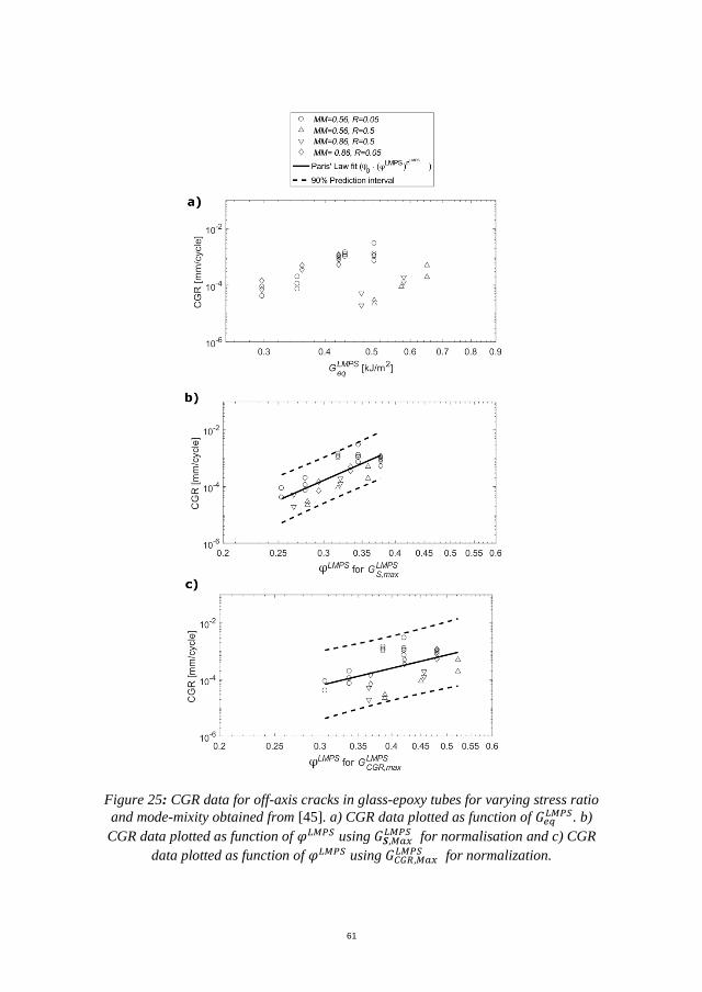
61
Figure 25: CGR data for off-axis cracks in glass-epoxy tubes for varying stress ratio
and mode-mixity obtained from [45]. a) CGR data plotted as function of 𝐺𝑒𝑞𝐿𝑀𝑃𝑆. b)
CGR data plotted as function of 𝜑𝐿𝑀𝑃𝑆 using 𝐺𝑺,𝑀𝑎𝑥𝐿𝑀𝑃𝑆 for normalisation and c) CGR
data plotted as function of 𝜑𝐿𝑀𝑃𝑆 using 𝐺𝐶𝐺𝑅,𝑀𝑎𝑥𝐿𝑀𝑃𝑆 for normalization.
CHARACTERIZATION AND MODELLING OF THE MULTIAXIAL FATIGUE RESPONSE OF GLASS FIBRE REINFORCED COMPOSITE MATERIALS
62
5.4. CONCLUSIONS
The research conducted in connection with modelling the mixed-mode crack
propagation under fatigue led to the following novel conclusions:
A novel physically based model for mixed-mode crack propagation in
composite materials has been established.
The local stress state in the failure process zone defines the type of damage
modes responsible for crack propagation.
The model is multi-scale and computationally efficient as it can be
evaluated using only the information available in micro-mechanical
models.
The derivation of evolution parameters requires the same test campaign as
used in the initiation model from [57], which means that only few tests are
needed to obtain evolution parameters describing the off-axis crack
evolution process.
63
CHAPTER 6. A MULTIAXIAL FATIGUE
MODEL FOR OFF-AXIS CRACK
EVOLUTION (PAPER #4)
In line with the overarching aim of the Ph.D. project, the last part of the project was
to develop a physically based multiaxial fatigue model for off-axis crack evolution.
At this instant in the project, an efficient material characterisation method had been
developed, the implementation of GLOB-LOC in an in-house code had been
validated, GLOB-LOC had been extended to provide necessary information about
the damaged laminate and lastly a physically based mixed-mode propagation model
had been proposed. All the constituents deemed necessary to propose a physically
based model of the off-axis crack evolution process were thereby in place.
Four models to predict off-axis crack evolution in composite laminates subjected to
fatigue loading have been identified in the open literature [68–71]. The models
proposed in [69–71] all describe off-axis crack evolution solely based on initiation
strength. Therefore, none of the models account for the influence of multiaxial loads
and the crack propagation aspect of the evolution process. Carraro [68] proposed an
off-axis evolution model considering both the initiation and propagation of off-axis
cracks. The model showed good agreement between the predicted and
experimentally measured crack density evolution. However, the model is
computationally expensive in terms of both memory and CPU-time as it is based on
a full Monte-Carlo simulation of the evolution process. Further on, some of the
parameters used in the model had to be determined from inverse modelling of the
crack density evolution curves, which questions whether the determined parameters
are material properties or ‘fitting’ parameters.
Therefore, it was decided to develop a new mechanistic model with the following
requirements guiding the development:
Use only physically based models for initiation, crack propagation and
damage description.
Capability of predicting crack density evolution in composite laminates
subjected to multiaxial loads at different load ratios.
Computationally efficient by adopting simplifying description of the crack
field.
CHARACTERIZATION AND MODELLING OF THE MULTIAXIAL FATIGUE RESPONSE OF GLASS FIBRE REINFORCED COMPOSITE MATERIALS
64
6.1. MODEL
As described in (Paper #2) the off-axis crack evolution process shows a
deterministic dependence on influencing factors such as stress level and constraining
effect, but the process is also stochastic. The deterministic influence of stress level
and stress ratio on initiation of off-axis cracks for each damage mode can be
described by a normalised SN-curve [57,68] given as
𝜓𝑑 = 𝜓0𝑑 ⋅ (𝑁𝑓𝑎𝑡)
𝑚𝑑
for d = LHS, LMPS
with 𝜓𝑑 =(1−𝑅𝑠
𝑑)𝜎𝑚𝑎𝑥𝑑
2𝜎𝑞𝑑−(1+𝑅𝑠
𝑑)𝜎𝑚𝑎𝑥𝑑 valid for 𝑅𝑠
𝑑 > 0
(24)
where 𝜎𝑞𝑑 is the static strengths, 𝑁𝑓𝑎𝑡 is the number of cycles to failure, 𝑅𝑠
𝑑 =𝜎𝑚𝑖𝑛
𝑑
𝜎𝑚𝑎𝑥𝑑
and 𝜓0𝑑 and 𝑚𝑑 are fitting parameters for the normalised SN Power law
relationships. The deterministic influence of stress level, stress ratio and
constraining effect on CGR for each propagation damage mode can be described by
a Paris like law (Paper #3) as:
𝐶𝐺𝑅𝑑 = 𝜑0𝑑 ⋅ (𝜑𝑑)𝑛𝑑
for d = LHS, LMPS
with 𝜑𝑑 =(1−𝑅𝑐
𝑑)√𝐺𝑚𝑎𝑥𝑑
2√𝐺𝑞𝑑−(1+𝑅𝑐
𝑑)√𝐺𝑚𝑎𝑥𝑑
valid for min (𝜎22) ≥ 0
(25)
where 𝐶𝐺𝑅𝑑 is the crack growth rate for a particular damage mode at the maximum
ERR loading and φ0𝑑 and 𝑛𝑑 are fitting parameters for the Paris’ Law relationships.
It should be noted that the normalisation in (26) has only been validated for 𝑅𝑠𝑑 > 0
and the normalisation in (27) has only been validated to work for situations where
crack faces remain stress free during the entire loading cycle, i.e. 𝜎22,𝑚𝑖𝑛 ≥ 0. The
stochastic nature of both crack initiation and crack growth are modelled using the
Weibull distributions. This result in two SN fields for initiation where the SN fields
for the initiation damage modes are given as:
𝑃𝑓𝑑(𝑁𝑓𝑎𝑡
𝑑 , 𝜎max𝑑 , 𝜎min
𝑑 ) = 1 − 𝑒𝑥𝑝
(
−
[
𝑁𝑓𝑎𝑡𝑑
(𝜓𝑑
𝜓0𝑑)
1
𝑚𝑑
] 𝛽𝑠
𝑑
)
for d = LHS, LMPS (26)
where 𝛽𝑠𝑑 is the Weibull shape parameters. In the same way for off-axis crack
propagation the crack growth fields are given as:
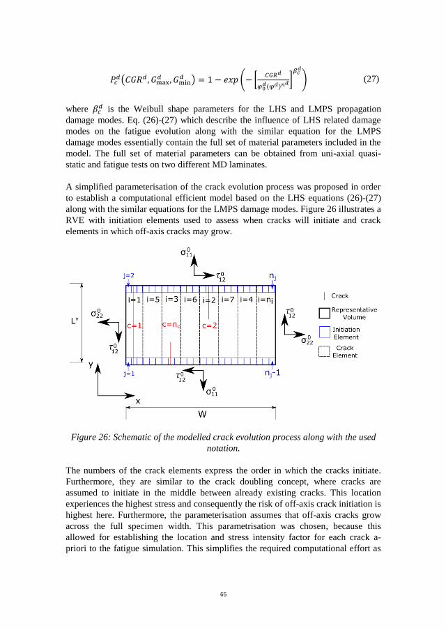
65
𝑃𝑐𝑑(𝐶𝐺𝑅𝑑 , 𝐺max
𝑑 , 𝐺min𝑑 ) = 1 − 𝑒𝑥𝑝 (− [
𝐶𝐺𝑅𝑑
𝜑0𝑑(φ𝑑)𝑛
𝑑]𝛽𝑐
𝑑
) (27)
where 𝛽𝑐𝑑 is the Weibull shape parameters for the LHS and LMPS propagation
damage modes. Eq. (26)-(27) which describe the influence of LHS related damage
modes on the fatigue evolution along with the similar equation for the LMPS
damage modes essentially contain the full set of material parameters included in the
model. The full set of material parameters can be obtained from uni-axial quasi-
static and fatigue tests on two different MD laminates.
A simplified parameterisation of the crack evolution process was proposed in order
to establish a computational efficient model based on the LHS equations (26)-(27)
along with the similar equations for the LMPS damage modes. Figure 26 illustrates a
RVE with initiation elements used to assess when cracks will initiate and crack
elements in which off-axis cracks may grow.
Figure 26: Schematic of the modelled crack evolution process along with the used
notation.
The numbers of the crack elements express the order in which the cracks initiate.
Furthermore, they are similar to the crack doubling concept, where cracks are
assumed to initiate in the middle between already existing cracks. This location
experiences the highest stress and consequently the risk of off-axis crack initiation is
highest here. Furthermore, the parameterisation assumes that off-axis cracks grow
across the full specimen width. This parametrisation was chosen, because this
allowed for establishing the location and stress intensity factor for each crack a-
priori to the fatigue simulation. This simplifies the required computational effort as

CHARACTERIZATION AND MODELLING OF THE MULTIAXIAL FATIGUE RESPONSE OF GLASS FIBRE REINFORCED COMPOSITE MATERIALS
66
the location does not need to be stored, and the stress intensity factors do not need to
be evaluated for each simulated cycle step.
The model should be evaluated through an iterative scheme and the flowchart for
simulation of an MD laminate is given in Figure 27.
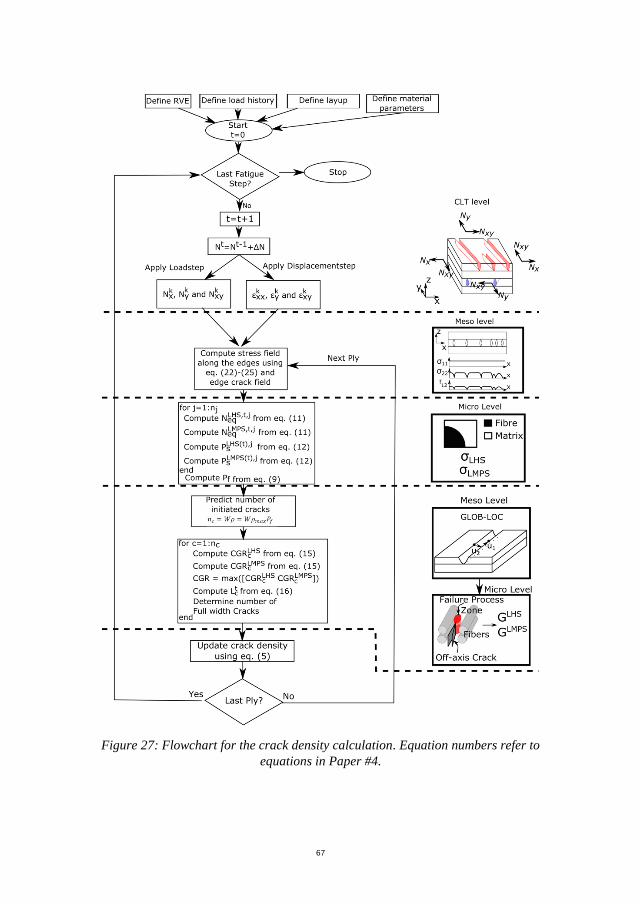
67
Figure 27: Flowchart for the crack density calculation. Equation numbers refer to
equations in Paper #4.
CHARACTERIZATION AND MODELLING OF THE MULTIAXIAL FATIGUE RESPONSE OF GLASS FIBRE REINFORCED COMPOSITE MATERIALS
68
6.2. RESULTS
Two different MD laminates were tested in order to obtain evolution parameters for
the LHS and LMPS damage modes. The obtained parameters are given in Table 3 in
(Paper#4). Using the determined parameters it was tested whether the model was
capable of predicting crack density evolution for another multiaxial stress state than
the ones from which the material parameters were determined. Further on, the
models applicability in terms of modelling the influence for VA block loading and a
change in stress ratio was also studied.
Comparison of model predictions with the measured crack density using ACC for
the thick layer in the [0/-60/0/60]s laminate tested in (Paper #2) is shown in Figure
28.
It is seen that model predictions agree well with the measured crack density.
Comparisons for the thin layer were not included, since the thin layer showed a
different crack evolution process, where cracks would not grow through the entire
width of the specimen. This violates the simplifying assumption used in the model
and consequently results in less accurate predictions.
6.3. CONCLUSIONS
The development of a multiaxial fatigue model for off-axis crack evolution resulted
in the following novel conclusions:
State-of-the-art physical based multiaxial fatigue models have been
combined into a multi-scale multiaxial fatigue model to predict off-axis
crack density evolution.
Material parameters to describe damage evolution for the LHS and LMPS
damage mechanisms have been derived using two different MD laminates
along with ACC.
The model has been shown to predict crack density evolution well for CA,
VA and C-T loading indicating that the modelling approach is successful at
modelling the different damage mechanisms leading to off-axis crack
propagation.
In its current form, the model is only capable of predicting crack density
evolution when cracks predominantly grow through the entire width of the
specimens. This is due to the simplified parametrisation used and this
parametrisation should therefore be improved in future versions, so more
generally applicable predictions can be made.
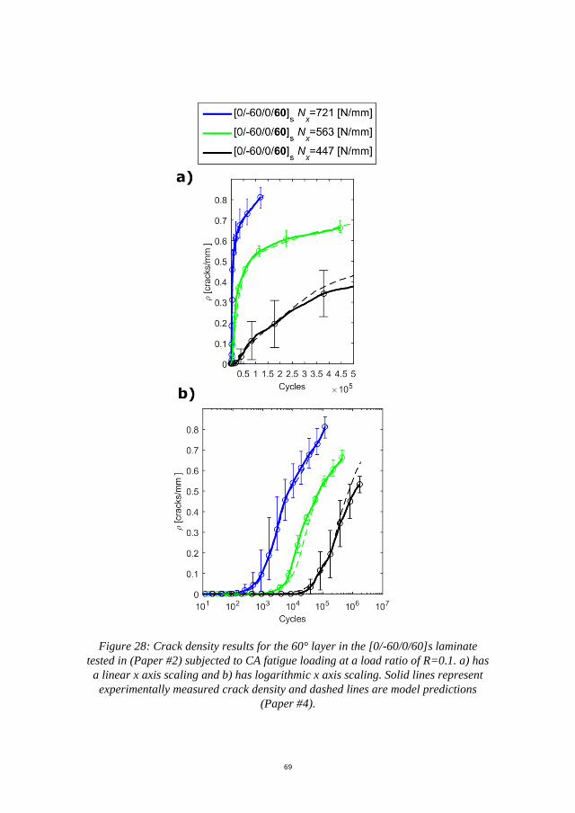
69
Figure 28: Crack density results for the 60° layer in the [0/-60/0/60]s laminate
tested in (Paper #2) subjected to CA fatigue loading at a load ratio of R=0.1. a) has
a linear x axis scaling and b) has logarithmic x axis scaling. Solid lines represent
experimentally measured crack density and dashed lines are model predictions
(Paper #4).
CHARACTERIZATION AND MODELLING OF THE MULTIAXIAL FATIGUE RESPONSE OF GLASS FIBRE REINFORCED COMPOSITE MATERIALS
70
CHAPTER 7. SUMMARY OF SCIENTIFIC
CONTRIBUTIONS
In this chapter, this Ph.D.’s main contributions and novelty of the work carried out
are highlighted. The contributions and novelty have been divided into knowledge
produced and methods developed.
(Paper #1) describes the first-ever method to automatically quantify off-axis cracks
in GFRP laminates. The method is called ACC, is non-destructive and eliminates the
manually and visually counting of off-axis cracks, which represents a labour
intensive and difficult task. The method therefore makes it possible to create better
direct comparison between test series and analyse more tests than was possible
before.
In the work of (Paper #2), ACC is combined with lock-in DIC and extensometer to
establish a method capable of assessing the damage in-situ in MD GFRP laminates.
This method is used to study the damage evolution in an MD laminate subjected to
CA T-T, CA C-T and VA T-T loading. This study led to an increased knowledge
about the damage evolution process as well as new methods to derive physically
based evolution parameters defining the off-axis crack evolution process. The new
knowledge included that crack density is a suitable damage measure for VA loading
and that T-T loading results in a higher crack density evolution rate and apparent
saturation value than C-T loading. Furthermore, the stochastic nature of off-axis
crack initiation and growth is accurately modelled by the Weibull distribution and
the shape-parameter of the Weibull distribution is constant for different stress levels.
The Weibull shape parameter therefore represents a material property needed to
model the off-axis crack evolution process. Additionally, new knowledge about the
performance of the GLOB-LOC model was obtained, where it was found that the
GLOB-LOC slightly under-predicts the stiffness of the degraded laminate but in
general can be considered accurate when compared to phenomenological approaches
like the sudden ply discount method.
(Paper #3) includes a reanalysis of observed and reported damage mechanisms
where epoxy is used to bond stiff constituents together. It was found that the same
two damage mechanisms have been observed and reported in numerous publications
for different epoxy material systems. From this knowledge, a physically based
model for mixed-mode crack propagation was proposed. The model predicts when
each of the two damage mechanisms occur and how they influence crack
propagation. The model is used to reanalyse crack growth data obtained from
literature and it was found that the model was capable of collapsing crack growth
data into one master curve for each of the two underlying damage mechanism.
Furthermore, the transition between master curves was predicted by the model to
71
occur at the same mode-mixity, where images of fracture surfaces reveal a shift in
damage mechanism. As the Ph.D. project focused on the modelling of off-axis
cracks, the work in (Paper #3) also included a new multi-scale modelling approach
to evaluate the physically mixed-mode crack propagation model in a computational
efficient manner.
The main contribution of the work presented in (Paper #4) is focused on method
development of a multi-scale multiaxial fatigue model for off-axis crack density
evolution. The model is based on a physically based model for off-axis crack
initiation obtained from literature, the mixed-mode propagation model from (Paper
#3) and the GLOB-LOC modelling framework. The work also includes an extension
of the GLOB-LOC model so additional information can be obtained from the model.
The additional information includes the influence of off-axis crack interaction on the
CSD and the ability to compute the varying stress field between off-axis cracks.
CHARACTERIZATION AND MODELLING OF THE MULTIAXIAL FATIGUE RESPONSE OF GLASS FIBRE REINFORCED COMPOSITE MATERIALS
72
CHAPTER 8. FUTURE WORK
As described in previous chapters, this Ph.D. project has solved problems in
measuring, quantifying and modelling the off-axis crack evolution process for
multiaxial fatigue loading. However, even though the present thesis establishes a
methodology to characterise a given GFRP material and uses this characterisation in
a modelling framework to predict the off-axis crack evolution, there still exist
several topics within the field of off-axis crack evolution that need further research.
The following list includes the main research gaps found at the completion of this
Ph.D. project.
Investigate whether the number of parameters needed in ACC can be
reduced in order to ease the use of the algorithm and study how changes in
the experimental setup (lighting conditions, camera alignment, specimen
thickness/transparency, resin, roving, fabric and stitching types etc.)
influence the counting.
In the study and determination of evolution parameters only isolated cracks
were considered. However, with the increased temporal resolution of the
crack evolution provided by ACC it would be interesting to study the
successive generation of non-isolated off-axis cracks. Such a study could
potentially provide further insight in how damage accumulates for VA
loading and which damage accumulation laws are applicable at the micro-
scale.
Both the initiation model used and the crack propagation model developed
in this research use a phenomenological approach to take into account the
load-ratio influence. For most composite structures (including wind turbine
blades), the load ratio does not remain constant during service. It is thus
clear, that there is a great need to gain further insight into how the load-
ratio influence the off-axis crack evolution and how to model it.
Since off-axis crack evolution is a hierarchical process involving several
different length scales, additional research is needed to clarify the influence
of the geometry of the test specimen/structure on the crack evolution
process in order to mature the methods for structural scale analysis.
It would be of great interest to composite manufactures to have models
capable of predicting ultimate structural failure, which is a feature not
included in the current model. Ultimate structural failure usually occurs as
a result of fibre failure in the laminate layers. The model proposed in this
Ph.D. project provides information on the load increase in the fibres when
off-axis cracks are present. It is not clear whether this information along
with SN-curves for fibre failure is sufficient to create accurate predictions
for fibre failure or if the off-axis crack evolution alters the damage process
in the fibres such that the fibre failure SN-curves no longer are applicable.

73
Additional research in clarifying the interaction between off-axis cracks
and fibre failure is therefore an important future research topic.
CHARACTERIZATION AND MODELLING OF THE MULTIAXIAL FATIGUE RESPONSE OF GLASS FIBRE REINFORCED COMPOSITE MATERIALS
74
LITERATURE LIST
[1] The European GRP market in 2016. Reinf Plast 2017;61:73–4.
doi:10.1016/j.repl.2017.01.026.
[2] Soden P., Kaddour A., Hinton M. Recommendations for designers and
researchers resulting from the world-wide failure exercise. Compos Sci
Technol 2004;64:589–604. doi:10.1016/S0266-3538(03)00228-8.
[3] Brondsted P, Nijssen RPL. Advances in wind turbine blade design and
materials. Woodhead Publishing; 2013.
[4] DNV-GL. DNVGL-ST-0376: Rotor blades for wind turbines. 2015.
[5] BSI. BS EN 61400-1 Wind Turbines - Design Requirements. 2005.
[6] Germanischer Lloyd. Guideline for the certification of wind turbines. 2003.
[7] Stevens RL, Fatemi A, Stephens RR, Fuchs HO. Metal fatigue in
engineering. 2nd ed. John Wiley & Sons, Inc; 2001.
[8] Schijve J. Fatigue of Structures and Materials. Secaucus, NJ, USA: Kluwer
Academic Publishers; 2001.
[9] Jamison, Russell D. Characterization and analysis of damage mechanisms in
tension-tension fatigue of graphite/epoxy laminates. vol. 1. ASTM
International; 1984.
[10] Quaresimin M, Susmel L, Talreja R. Fatigue behaviour and life assessment
of composite laminates under multiaxial loadings. Int J Fatigue 2010;32:2–
16. doi:10.1016/j.ijfatigue.2009.02.012.
[11] Degrieck J, Van Paepegem W. Fatigue damage modeling of fibre-reinforced
composite materials: Review. Appl Mech Rev 2001;54:279.
doi:10.1115/1.1381395.
[12] Quaresimin M. 50 th anniversary article: multiaxial fatigue testing of
composites: from the pioneers to future directions. Strain 2015;51:16–29.
doi:10.1111/str.12124.
[13] Talreja R. Multi-scale modeling in damage mechanics of composite
materials. J Mater Sci 2006;41:6800–12. doi:10.1007/s10853-006-0210-9.
[14] Lundmark P, Varna J. Constitutive relationships for laminates with ply
cracks in in-plane loading. Int J Damage Mech 2005;14:235–59.
doi:10.1177/1056789505050355.
[15] Wharmby A. Observations on damage development in fibre reinforced
polymer laminates under cyclic loading. Int J Fatigue 2003;25:437–46.
doi:10.1016/s0142-1123(02)00118-4.
APPENDIX A.
75
[16] Zangenberg J, Brondsted P, Gillespie JW. Fatigue damage propagation in
unidirectional glass fibre reinforced composites made of a non-crimp fabric.
J Compos Mater 2013;48:2711–27. doi:10.1177/0021998313502062.
[17] Tong J, Guild FJ, Ogin SL, Smith PA. Off-axis fatigue crack growth and the
associated energy release rate in composite laminates. Appl Compos Mater
1997;4:349–59. doi:10.1007/BF02481399.
[18] Wharmby AW, Ellyin F. Damage growth in constrained angle-ply laminates
under cyclic loading. Compos Sci Technol 2002;62:1239–47.
doi:10.1016/s0266-3538(02)00075-1.
[19] Adden S, Horst P. Stiffness degradation under fatigue in multiaxially loaded
non-crimped-fabrics. Int J Fatigue 2010;32:108–22.
doi:10.1016/j.ijfatigue.2009.02.002.
[20] Quaresimin M, Carraro PA, Mikkelsen LP, Lucato N, Vivian L, Brøndsted
P, et al. Damage evolution under cyclic multiaxial stress state: A
comparative analysis between glass/epoxy laminates and tubes. Compos Part
B Eng 2014;61:282–90. doi:10.1016/j.compositesb.2014.01.056.
[21] Kaddour A, Hinton M, Smith P, Li S. The background to the third world-
wide failure exercise. J Compos Mater 2013;47:2417–26.
doi:10.1177/0021998313499475.
[22] Emery TR, Dulieu-Barton JM. Thermoelastic Stress Analysis of damage
mechanisms in composite materials. Compos Part A Appl Sci Manuf
2010;41:1729–42. doi:10.1016/j.compositesa.2009.08.015.
[23] Battams G. The use of optical techniques to assess the damage tolerance of
composite materials, PhD dissertation. phdthesis. University of
Southampton, 2014.
[24] Li L, Lomov S V, Yan X, Carvelli V. Cluster analysis of acoustic emission
signals for 2D and 3D woven glass/epoxy composites. Compos Struct
2014;116:286–99. doi:10.1016/j.compstruct.2014.05.023.
[25] Guild FJ, Vrellos N, Drinkwater BW, Balhi N, Ogin SL, Smith PA. Intra-
laminar cracking in CFRP laminates: observations and modelling. J Mater
Sci 2006;41:6599–609. doi:10.1007/s10853-006-0199-0.
[26] Sket F, Enfedaque A, Alton C, González C, Molina-Aldareguia JM, Llorca
J. Automatic quantification of matrix cracking and fiber rotation by X-ray
computed tomography in shear-deformed carbon fiber-reinforced laminates.
Compos Sci Technol 2014;90:129–38.
doi:10.1016/j.compscitech.2013.10.022.
[27] Sisodia S, Gamstedt EK, Edgren F, Varna J. Effects of voids on quasi-static
and tension fatigue behaviour of carbon-fibre composite laminates. J
Compos Mater 2015;49:2137–48. doi:10.1177/0021998314541993.
CHARACTERIZATION AND MODELLING OF THE MULTIAXIAL FATIGUE RESPONSE OF GLASS FIBRE REINFORCED COMPOSITE MATERIALS
76
[28] Wolodko JD, Hoover JW, Ellyin F. Detection of transverse cracks in GFRP
composites using digital image processing. In: Ellyin F, Provan JW, editors.
Prog. Mech. Behav. Mater. (ICM8), vol 2 Mater. Prop., University of
Victoria, Departement of Mechanical Engineering; 1999, p. 483–7.
[29] Glud JA, Dulieu-Barton JM, Thomsen OT, Overgaard LCT. Automated
counting of off-axis tunnelling cracks using digital image processing.
Compos Sci Technol 2016;125:80–9.
doi:10.1016/j.compscitech.2016.01.019.
[30] Daugman JG. Uncertainty relation for resolution in space, spatial frequency,
and orientation optimized by two-dimensional visual cortical filters. JOSA
A 1985;2:1160–9.
[31] Otsu N. A threshold selection method from gray-level histograms. IEEE
Trans Syst Man Cybern 1979;9:62–6.
[32] Lam L, Lee SW, Suen C. Thinning methodologies: a comprehensive survey.
IEEE Trans Pattern Anal Mach Intell 1992;14:869–85.
[33] Nijssen R. Optidat - database reference document. Kluisgat 5 1771 MV
Wieringerwerf, the Netherlands: 2006.
[34] Mandell JF, Samborsky D. DOE / MSU composite material fatigue
database. 2009.
[35] Jones RM. Mechanics of Composite Materials. 2nd ed. Taylor & Francis
Group; 1999.
[36] Shokrieh MM, Lessard LB. Progressive fatigue damage modeling of
composite materials, Part I: Modeling. J Compos Mater 2000;34:1056–80.
doi:10.1177/002199830003401301.
[37] Eliopoulos EN, Philippidis TP. A progressive damage simulation algorithm
for GFRP composites under cyclic loading. Part I: Material constitutive
model. Compos Sci Technol 2011;71:742–9.
doi:10.1016/j.compscitech.2011.01.023.
[38] Kennedy CR, Brádaigh CMÓ, Leen SB. A multiaxial fatigue damage model
for fibre reinforced polymer composites. Compos Struct 2013;106:201–10.
doi:10.1016/j.compstruct.2013.05.024.
[39] Passipoularidis VA, Philippidis TP, Brondsted P. Fatigue life prediction in
composites using progressive damage modelling under block and spectrum
loading. Int J Fatigue 2011;33:132–44. doi:10.1016/j.ijfatigue.2010.07.011.
[40] Tong J, Guild FJ, Ogin SL, Smith PA. On matrix crack growth in quasi-
isotropic laminates - I. Experimental investigation. Compos Sci Technol
1997;57:1527–35. doi:10.1016/s0266-3538(97)00080-8.
APPENDIX A.
77
[41] Adden S, Horst P. Damage propagation in non-crimp fabrics under bi-axial
static and fatigue loading. Compos Sci Technol 2006;66:626–33.
doi:10.1016/j.compscitech.2005.07.034.
[42] Li C, Ellyin F, Wharmby A. On matrix crack saturation in composite
laminates. Compos Part B Eng 2003;34:473–80. doi:10.1016/S1359-
8368(03)00020-9.
[43] Fruehmann RK, Dulieu-Barton JM, Quinn S, Tyler JP. The use of a lock-in
amplifier to apply digital image correlation to cyclically loaded components.
Opt Lasers Eng 2015;68:149–59. doi:10.1016/j.optlaseng.2014.12.021.
[44] Reifsnider KL. Damage in composite materials: basic mechanisms,
accumulation, tolerance, and characterization. ASTM; 1982.
doi:10.1520/STP775-EB.
[45] Quaresimin M, Carraro PA, Maragoni L. Influence of load ratio on the
biaxial fatigue behaviour and damage evolution in glass/epoxy tubes under
tension–torsion loading. Compos Part A Appl Sci Manuf 2015;78:294–302.
doi:10.1016/j.compositesa.2015.08.009.
[46] Boniface L, Ogin SL. Application of the paris equation to the fatigue growth
of transverse ply cracks. J Compos Mater 1989;23:735–54.
doi:10.1177/002199838902300706.
[47] Singh C V, Talreja R. A synergistic damage mechanics approach for
composite laminates with matrix cracks in multiple orientations. Mech
Mater 2009;41:954–68. doi:10.1016/j.mechmat.2009.02.008.
[48] Carraro PA, Quaresimin M. A stiffness degradation model for cracked
multidirectional laminates with cracks in multiple layers. Int J Solids Struct
2015;58:34–51. doi:10.1016/j.ijsolstr.2014.12.016.
[49] Nairn JA, Mendels DA. On the use of planar shear-lag methods for stress-
transfer analysis of multilayered composites. Mech Mater 2001;33:335–62.
doi:10.1016/S0167-6636(01)00056-4.
[50] Hashin Z. Analysis of cracked laminates: a variational approach. Mech
Mater 1985;4:121–36. doi:10.1016/0167-6636(85)90011-0.
[51] Lundmark P, Varna J. Crack face sliding effect on stiffness of laminates
with ply cracks. Compos Sci Technol 2006;66:1444–54.
doi:10.1016/j.compscitech.2005.08.016.
[52] Lundmark P, Varna J. Stiffness reduction in laminates at high intralaminar
crack density: effect of crack interaction n.d.
doi:10.1177/1056789509351840.
[53] Varna J. Modelling mechanical performance of damaged laminates. J
Compos Mater 2013;47:2443–74. doi:10.1177/0021998312469241.
CHARACTERIZATION AND MODELLING OF THE MULTIAXIAL FATIGUE RESPONSE OF GLASS FIBRE REINFORCED COMPOSITE MATERIALS
78
[54] Quaresimin M, Carraro PA, Maragoni L. Early stage damage in off-axis
plies under fatigue loading. Compos Sci Technol 2016;128:147–54.
doi:10.1016/j.compscitech.2016.03.015.
[55] Varna J, Krasnikovs A, Kumar RS, Talreja R. A synergistic damage
mechanics approach to viscoelastic response of cracked cross-ply laminates.
Int J Damage Mech 2004;13:301–34. doi:10.1177/1056789504042457.
[56] Nairn JA, Hu S, Bark JS. A critical evaluation of theories for predicting
microcracking in composite laminates. J Mater Sci 1993;28:5099–111.
doi:10.1007/BF00361186.
[57] Carraro PA, Quaresimin M. A damage based model for crack initiation in
unidirectional composites under multiaxial cyclic loading. Compos Sci
Technol 2014;99:154–63. doi:10.1016/j.compscitech.2014.05.012.
[58] Quaresimin M, Carraro PA. Damage initiation and evolution in glass/epoxy
tubes subjected to combined tension-torsion fatigue loading. Int J Fatigue
2014;63:25–35. doi:10.1016/j.ijfatigue.2014.01.002.
[59] Carraro PA, Meneghetti G, Quaresimin M, Ricotta M. Crack propagation
analysis in composite bonded joints under mixed-mode (I+II) static and
fatigue loading: experimental investigation and phenomenological
modelling. J Adhes Sci Technol 2013;27:1179–96.
doi:10.1080/01694243.2012.735902.
[60] Bürger D, Rans CD, Benedictus R. Influence of fabric carrier on the fatigue
disbond behavior of metal-to-metal bonded interfaces. J Adhes 2013.
[61] Armanios E, Bucinell R, Wilson D, Asp L, Sjogren A, Greenhalgh E.
Delamination growth and thresholds in a carbon/epoxy composite under
fatigue loading. J Compos Technol Res 2001;23:55.
doi:10.1520/CTR10914J.
[62] Liu Z, Gibson RF, Newaz GM. The use of a modified mixed mode bending
test for characterization of mixed-mode fracture behavior of adhesively
bonded metal joints. J Adhes 2010;78:223–44.
doi:10.1080/00218460210408.
[63] Purslow D. Matrix fractography of fibre-reinforced epoxy composites.
Composites 1986;17:289–303. doi:10.1016/0010-4361(86)90746-9.
[64] Tanaka H, Tanaka K, Tsuji T, Katoh H. Mixed-mode (I+II) propagation of
delamination fatigue cracks in unidirectional graphite/epoxy laminates.
Trans Japan Soc Mech Eng Ser A 1999;65:1676–83.
doi:10.1299/kikaia.65.1676.
[65] Kenane M, Benzeggagh ML. Mixed-mode delamination fracture toughness
of unidirectional glass/epoxy composites under fatigue loading. Compos Sci
Technol 1997;57:597–605. doi:10.1016/S0266-3538(97)00021-3.
APPENDIX A. (PAPER #1)
79
[66] Bürger D. Mixed-mode fatigue disbond on metallic bonded joints, PhD
dissertation. Delft University of Technology, 2015.
[67] Kawai M, Suda H. Effects of Non-Negative Mean Stress on the Off-Axis
Fatigue Behavior of Unidirectional Carbon/Epoxy Composites at Room
Temperature. J Compos Mater 2004;38:833–54.
doi:10.1177/0021998304042477.
[68] Carraro PA. Multiaxial fatigue behaviour of composite materials:
characterisation and modelling. PhD dissertation. University of Padova,
2014.
[69] Sun Z, Daniel IM, Luo JJ. Modeling of fatigue damage in a polymer matrix
composite. Mater Sci Eng A 2003;361:302–11. doi:10.1016/S0921-
5093(03)00556-2.
[70] Huang Y. Stochastic damage evolution under static and fatigue loading in
composites with manufacturing defects. PhD dissertation. Texas A&M
University, 2012.
[71] Kahla H Ben, Varna J, Pupurs A. Microcracking in layers of composite
laminates in cyclic loading with tensile transverse stress component in
layers. 20th Int. Conf. Compos. Mater., 2015.

CHARACTERIZATION AND MODELLING OF THE MULTIAXIAL FATIGUE RESPONSE OF GLASS FIBRE REINFORCED COMPOSITE MATERIALS
80
Appendix A. (Paper #1)

APPENDIX B. (PAPER #2)
81
Appendix B. (Paper #2)

CHARACTERIZATION AND MODELLING OF THE MULTIAXIAL FATIGUE RESPONSE OF GLASS FIBRE REINFORCED COMPOSITE MATERIALS
82
Appendix C. (Paper #3)

APPENDIX D. (PAPER #4)
83
Appendix D. (Paper #4)

JENS G
LUD
C
HA
RA
CTER
IZATION
AN
D M
OD
ELLING
OF TH
E MU
LTIAXIA
L FATIGU
E RESPO
NSE O
F GLA
SS FIBR
E REIN
FOR
CED
CO
MPO
SITE MATER
IALS
ISSN (online): 2446-1636ISBN (online): 978-87-7112-961-8