Embed Size (px)
Citation preview

2004-04-23 IEEE L802.16-04/14
0
Project IEEE 802.16 Broadband Wireless Access Working Group <http://ieee802.org/16>
Title Characteristics of Wireless Metropolitan Area Networks – Follow up to contribution to ITU-R
DateSubmitted
2002-04-22
Source(s) José M. CostaNortel NetworksP.O. Box C-3511Ottawa, OntarioCANADA K1Y 4H7
Voice: +1 613 763-7574Fax: +1 613 [email protected]
Re: IEEE Contribution to ITU-R Joint Task Group 6-8-9, Document IEEE L802.16-04/11
Abstract This documents provides information about the results of the meeting of ITU-R JTG 6-8-9(Geneva, 22-26 March 2004), in particular the IEEE contribution on Characteristics of WirelessMetropolitan Area Networks.
Purpose For information of IEEE 802.16 and to propose that further details on Characteristics ofWireless Metropolitan Area Networks be provided to ITU-R JTG 6-8-9 by November 2004.
Notice This document has been prepared to assist IEEE 802.16. It is offered as a basis for discussion and isnot binding on the contributing individual(s) or organization(s). The material in this document issubject to change in form and content after further study. The contributor(s) reserve(s) the right toadd, amend or withdraw material contained herein.
Release The contributor grants a free, irrevocable license to the IEEE to incorporate material contained inthis contribution, and any modifications thereof, in the creation of an IEEE Standards publication; tocopyright in the IEEE’s name any IEEE Standards publication even though it may include portionsof this contribution; and at the IEEE’s sole discretion to permit others to reproduce in whole or inpart the resulting IEEE Standards publication. The contributor also acknowledges and accepts thatthis contribution may be made public by IEEE 802.16.
PatentPolicy andProcedures
The contributor is familiar with the IEEE 802.16 Patent Policy and Procedures<http://ieee802.org/16/ipr/patents/policy.html>, including the statement "IEEE standards may includethe known use of patent(s), including patent applications, provided the IEEE receives assurance fromthe patent holder or applicant with respect to patents essential for compliance with both mandatoryand optional portions of the standard." Early disclosure to the Working Group of patent informationthat might be relevant to the standard is essential to reduce the possibility for delays in thedevelopment process and increase the likelihood that the draft publication will be approved forpublication. Please notify the Chair <mailto:[email protected]> as early as possible, in writtenor electronic form, if patented technology (or technology under patent application) might beincorporated into a draft standard being developed within the IEEE 802.16 Working Group. TheChair will disclose this notification via the IEEE 802.16 web site<http://ieee802.org/16/ipr/patents/notices>.

2004-04-23 IEEE L802.16-04/14
1
Characteristics of Wireless Metropolitan Area Networks –Follow up to contribution to ITU-R
José M. CostaNortel Networks
1. Introduction
The purpose of this contribution is to provide a brief report of the results of the IEEE contribution to ITU-RJTG 6-8-9 (Document IEEE L802.16-04/11), which was well received by JTG 6-8-9.
It is also proposed that that further details on Characteristics of Wireless Metropolitan Area Networks beprovided to ITU-R JTG 6-8-9 by November 2004.
2. Highlights of ITU-R JTG 6-8-9
ITU-R Joint Task Group 6-8-9 (JTG 6-8-9) held its first meeting from 22 to 26 March 2004 in Geneva. Thepurpose of JTG 6-8-9 is to prepare draft CPM1 text on WRC-07 Agenda Item 1.92. Based on the inputcontributions, the work addressed four areas:
1. Characteristics of terrestrial systems
2. Electronic News Gathering (ENG issues)
3. Methodologies for sharing between space services and terrestrial services
4. Results of studies on sharing between Mobile Satellite Service (MSS) and Mobile Service (MS)components of IMT-2000.
The results are in the chairman’s report (ITU-R Doc. 6-8-9/26), which is available from the ITU web site forthose with a TIES3 userid. The following table summarizes the activities of JTG 6-8-9 and the documents ofthis group are available here:
http://www.itu.int/md/meetingdoc.asp?lang=e&type=sfolders&parent=R03-6.8.9-C
(IEEE 802.16 members without a TIES userid may ask the IEEE 802.16 ITU-R Liaison Officer4 for a copy ofdocuments required).
1 Conference Preparatory Meeting (CPM), a meeting held prior to a World Radiocommunication Conference (WRC).2 Agenda item 1.9 is “to review the technical, operational and regulatory provisions applicable to the use of the
band 2 500-2 690 MHz by space services in order to facilitate sharing with current and future terrestrial serviceswithout placing undue constraint on the services to which the band is allocated”.
3 http://www.itu.int/TIES/intro.html4 [email protected]

2004-04-23 IEEE L802.16-04/14
2
Ad-hoc group(Chairman)
Mandate Documents
AH-1 – Characteristics ofterrestrial systems
(Mr. R. Ferguson, USA)
Prepare a document listingcharacteristics of terrestrial FS and MSsystems.
6-8-9/12, 13, 14, 19, 20,21, 22
AH-2 – ENG issues
(Mr. M. Dupuis, CAN)
Review studies conducted by WP 6P(Doc. 6P/14) and determine elementsrelevant to JTG 6-8-9; prepare, ifnecessary, a liaison to WP 6P.
6-8-9/1 (6P/14), 2 (4B/6),4, 5, 8, 11
AH-3 – Methodologies forsharing between spaceservices and terrestrialservices
(Mme C. Ganne, France)
Review methodologies to determinewhich are applicable to various sharingsituations and prepare list of elementsthat need to be developed to completethe studies.
6-8-9/1 (6P/14 – Partdealing withmethodology), 2 (6S/346),2 (8F/915), 12, 19, 20, 22(Dealing withmethodology)
AH-4 – Results of studies onsharing between MSS andMS components of IMT-2000
(Mr. K. Kosaka, Japan)
Review results of studies conductedby SG 8 to determine if anyconclusions can be drawn with regardsto sharing between MSS and MS andassess need for further studies.Document any conclusive results, ifapplicable, as draft CPM text.
6-8-9/ 9, 10, 16(Section 2.1), 18, 22
The IEEE Contribution “Characteristics of Wireless Metropolitan Area Networks” (ITU-R Doc. 6-8-9/21):
was well received by JTG 6-8-9 and, together with other contributions on terrestrial systems characteristics,formed the basis for a Working Document on “Characteristics of terrestrial systems for consideration in studiesunder Agenda Item 1.9 of WRC-07” (Annex 3 to Doc. 6-8-9/26):
In the ITU-R Working Document, Section 4 on “Characteristics of Wireless Metropolitan Area Networks” isonly a placeholder for now. It is proposed that IEEE 802.16 provides text with characteristics of IEEE 802.16systems in the band 2500 – 2690 MHz, by extracting relevant material from the IEEE 802.16 standard and/or

2004-04-23 IEEE L802.16-04/14
3
providing characteristics of typical implementations. The characteristics of other terrestrial systems containedin the ITU-R Working Document may serve as guide for the type of information that is needed.
The second meeting of JTG 6-8-9 is tentatively scheduled for 17-21 January 2005 in Geneva, Switzerland, butthere is a chance that this may change within the time range December 2004 – January 2005. To be safe, acontribution from IEEE should be ready by November 2004.
IEEE 802.16 should prepare the material and work with IEEE 802.18 for final approval as an IEEE contributionand submission to ITU-R JTG 6-8-9.
3. Proposal
It is proposed that IEEE 802.16 gather information on parameters of typical IEEE 802.16 systems in the band2500-2690 MHz with a view of developing a future contribution to ITU-R.
____________________
DOCUMENT IN L80216-04_13.DOC 23.04.04 23.04.04
Received: 19 March 2004
Institute of Electrical and Electronics Engineers (IEEE)
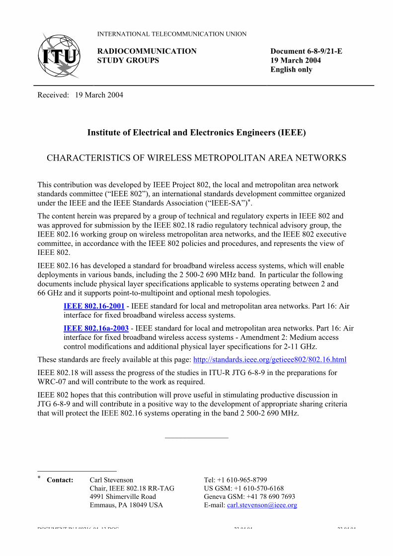
CHARACTERISTICS OF WIRELESS METROPOLITAN AREA NETWORKS
This contribution was developed by IEEE Project 802, the local and metropolitan area networkstandards committee (“IEEE 802”), an international standards development committee organizedunder the IEEE and the IEEE Standards Association (“IEEE-SA”)*.
The content herein was prepared by a group of technical and regulatory experts in IEEE 802 andwas approved for submission by the IEEE 802.18 radio regulatory technical advisory group, theIEEE 802.16 working group on wireless metropolitan area networks, and the IEEE 802 executivecommittee, in accordance with the IEEE 802 policies and procedures, and represents the view ofIEEE 802.
IEEE 802.16 has developed a standard for broadband wireless access systems, which will enabledeployments in various bands, including the 2 500-2 690 MHz band. In particular the followingdocuments include physical layer specifications applicable to systems operating between 2 and66 GHz and it supports point-to-multipoint and optional mesh topologies.
IEEE 802.16-2001 - IEEE standard for local and metropolitan area networks. Part 16: Airinterface for fixed broadband wireless access systems.
IEEE 802.16a-2003 - IEEE standard for local and metropolitan area networks. Part 16: Airinterface for fixed broadband wireless access systems - Amendment 2: Medium accesscontrol modifications and additional physical layer specifications for 2-11 GHz.
These standards are freely available at this page: http://standards.ieee.org/getieee802/802.16.html
IEEE 802.18 will assess the progress of the studies in ITU-R JTG 6-8-9 in the preparations forWRC-07 and will contribute to the work as required.
IEEE 802 hopes that this contribution will prove useful in stimulating productive discussion inJTG 6-8-9 and will contribute in a positive way to the development of appropriate sharing criteriathat will protect the IEEE 802.16 systems operating in the band 2 500-2 690 MHz.
________________
____________________* Contact: Carl Stevenson Tel: +1 610-965-8799
Chair, IEEE 802.18 RR-TAG US GSM: +1 610-570-61684991 Shimerville Road Geneva GSM: +41 78 690 7693Emmaus, PA 18049 USA E-mail: [email protected]
INTERNATIONAL TELECOMMUNICATION UNION
Document 6-8-9/21-E19 March 2004
RADIOCOMMUNICATIONSTUDY GROUPS
English only

DOCUMENT IN L80216-04_13.DOC 23.04.04 23.04.04
Source: Document 6-8-9/TEMP/4
Annex 3 to JTG 6-8-9 Chairman’s Report
CHARACTERISTICS OF TERRESTRIAL SYSTEMS FOR CONSIDERATION INSTUDIES UNDER AGENDA ITEM 1.9 OF WRC-07
Introduction
A list of terrestrial characteristics have been compiled below based on input documents received atthe first meeting of JTG 6-8-9. Input documents considered for this compilation are: 6-8-9/12, 13,14, 19, 20, 21, 22.
Characteristics for Terrestrial Systems
1 Fixed Station Equipment Characteristics
Point-to-point (P-P) FS systems (Source: Doc 6-8-9/12 (WP 9D))
Antenna diameter (m) 3 1.2
Maximum receive antenna gain (dBi) 36 28
Feeder loss (dB) 3 3
Noise figure (dB) 4 4
Elevation angle (degrees) 0 0
INTERNATIONAL TELECOMMUNICATION UNION
Annex 3 toDocument 6-8-9/26-E30 March 2004
RADIOCOMMUNICATIONSTUDY GROUPS
English only

- 2 -6-8-9/26(Annex 3)-E
DOCUMENT IN L80216-04_13.DOC 23.04.04 23.04.04
Hub-stations Receive Parameters of Point-to-Multipoint (P-MP) FS systems
Fixed base station receive parameters
Characteristics USA Doc 13 USA Doc 13 9D Doc 12 9D Doc 12 CAN Doc 20 CAN Doc 20
Cell size (km radius) 561 3-102
Antenna type Omni or sectored 120˚ sector Omnidirection Sectoral Omnidirection Sectoral
Max antenna gain (dBi) 19(including
feeder loss)
18(including
feeder loss)
10 15 13 17
Downtilt angle (˚) .5 1 0 0 0 0
Antenna height (m) HAAT3 1000 50
Polarization Linear Linear
Receiver noise figure (dB) 2.5 3 4 4 4 4
Receiver thermal noise(dBW/MHz)
-141.5 –141
Trigger for Sharing Studies(Isat/Nth) (dB)
-10 -10
Adjacent channelselectivity
FDD: varies 4
TDD: varies 4FDD: varies 4
TDD: varies 4
Feeder Loss 4 4 3 3
Beamwidth in elevation(degrees)
5 7
Beamwidth in Azimuth(degrees)
N/A 90 N/A 90
1) Rural areas.
2) Urban areas.
3) HAAT = Height Above Average Terrain
4) Varies by supplier.
- 3 -6-8-9/26(Annex 3)-E
DOCUMENT IN L80216-04_13.DOC 23.04.04 23.04.04
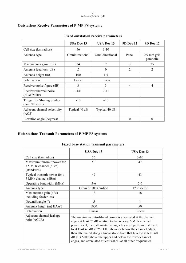
Outstations Receive Parameters of P-MP FS systems
Fixed outstation receive parameters
USA Doc 13 USA Doc 13 9D Doc 12 9D Doc 12
Cell size (km radius) 56 3-10
Antenna type Omnidirectional Omnidirectional Panel 0.9 mm gridparabolic
Max antenna gain (dBi) 24 7 17 25
Antenna feed loss (dB) .5 0 2 2
Antenna height (m) 100 1.5
Polarization Linear Linear
Receiver noise figure (dB) 3 3 4 4
Receiver thermal noise(dBW/MHz)
–141 -141
Trigger for Sharing Studies(Isat/Nth) (dB)
-10 –10
Adjacent channel selectivity(ACS)
Typical 40 dB Typical 40 dB
Elevation angle (degrees) 0 0
Hub-stations Transmit Parameters of P-MP FS systems
Fixed base station transmit parameters
USA Doc 13 USA Doc 13
Cell size (km radius) 56 3-10Maximum transmit power fora 5 MHz channel (dBm)(standards)
50 47
Typical transmit power for a5 MHz channel (dBm)
47 43
Operating bandwidth (MHz) 5-6 5-6Antenna type Omni or 180 Cardiod 120˚ sectorMax antenna gain (dBi)including feeder loss
13 18
Downtilt angle (˚) .5 1Antenna height (m) HAAT 1000 50Polarization Linear LinearAdjacent channel leakageratio (ACLR)
The maximum out-of-band power is attenuated at the channeledges at least 25 dB relative to the average 6 MHz channelpower level, then attenuated along a linear slope from that levelto at least 40 dB at 250 kHz above or below the channel edges,then attenuated along a linear slope from that level to at least 60dB at 3 MHz above the upper and below the lower channeledges, and attenuated at least 60 dB at all other frequencies.
- 4 -6-8-9/26(Annex 3)-E
DOCUMENT IN L80216-04_13.DOC 23.04.04 23.04.04
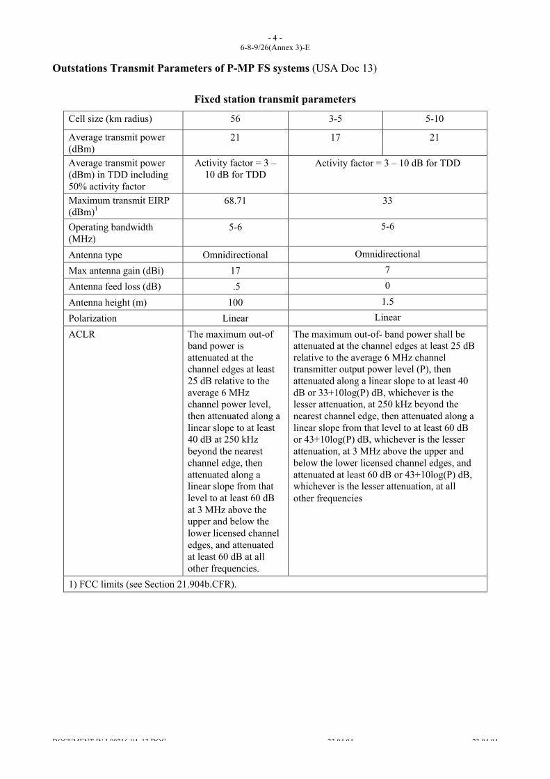
Outstations Transmit Parameters of P-MP FS systems (USA Doc 13)
Fixed station transmit parameters
Cell size (km radius) 56 3-5 5-10
Average transmit power(dBm)
21 17 21
Average transmit power(dBm) in TDD including50% activity factor
Activity factor = 3 –10 dB for TDD
Activity factor = 3 – 10 dB for TDD
Maximum transmit EIRP(dBm)1
68.71 33
Operating bandwidth(MHz)
5-6 5-6
Antenna type Omnidirectional Omnidirectional
Max antenna gain (dBi) 17 7
Antenna feed loss (dB) .5 0
Antenna height (m) 100 1.5
Polarization Linear Linear
ACLR The maximum out-ofband power isattenuated at thechannel edges at least25 dB relative to theaverage 6 MHzchannel power level,then attenuated along alinear slope to at least40 dB at 250 kHzbeyond the nearestchannel edge, thenattenuated along alinear slope from thatlevel to at least 60 dBat 3 MHz above theupper and below thelower licensed channeledges, and attenuatedat least 60 dB at allother frequencies.
The maximum out-of- band power shall beattenuated at the channel edges at least 25 dBrelative to the average 6 MHz channeltransmitter output power level (P), thenattenuated along a linear slope to at least 40dB or 33+10log(P) dB, whichever is thelesser attenuation, at 250 kHz beyond thenearest channel edge, then attenuated along alinear slope from that level to at least 60 dBor 43+10log(P) dB, whichever is the lesserattenuation, at 3 MHz above the upper andbelow the lower licensed channel edges, andattenuated at least 60 dB or 43+10log(P) dB,whichever is the lesser attenuation, at allother frequencies
1) FCC limits (see Section 21.904b.CFR).

- 5 -6-8-9/26(Annex 3)-E
DOCUMENT IN L80216-04_13.DOC 23.04.04 23.04.04
2 IMT-2000 Characteristics (Source: Report ITU-R M.2039, Doc 6-8-9/19)
TABLE 2
Characteristics of IMT-2000 mobile stations
IMT-2000 CDMA TDD(time-code)
Parameter IMT-2000 CDMADirect Spread
See [Ref. 1]
IMT-2000 CDMAMulti-Carrier1
1.28 Mchip/slow chip rate
See [Ref. 2]
3.84 Mchip/shigh chip rate
See [Ref. 2]
IMT-2000 TDMASingle-Carrier
IMT-2000FDMA/TDMA
(frequency-time)
See [Ref. 5]
Carrier spacing 5 MHz ±n _ 0.2 MHz
1.25 MHz (1X) 3.75 MHz (3X) 1.6 MHz ±n _ 0.2 MHz
5 MHz ±n _ 0.2 MHz
30 kHzSee [Ref. 14]
200 kHzSee [Ref. 7]
1.728 MHz
Duplex method FDD FDD FDD TDD TDD FDD FDD TDD
Transmitter power,dBm (typical)i
20 20 20 20 20 20 20 10
Transmitter power,dBm (maximum)
24 or 21 24 24 24 or 21 24 or 21 30See [Ref. 15]
30See [Ref. 8]
24
Antenna gain (dBi) 0 0 0 0 0 0 0 0
Antenna height (m) 1.5 1.5 1.5 1.5 1.5 1.5 1.5 1.5
Access techniques CDMAiii CDMA CDMA TDMA/CDMA TDMA/CDMA TDMASee [Ref. 15]
TDMAii MC/TDMAiv
Data rates supported Pedestrian:384 kbit/s,Vehicular:
144 kbit/s, Indoors:2 Mbit/s
Higher data rates upto 10 Mbit/s are
supported bytechnology
enhancements(HSDPA), See [Ref.
25]
Up to625.35 kbit/s onforward link and
up to 433.35kbit/s on reverse
linkHigher data ratesup to 2 457 kbit/sare supported by
technologyenhancements
(HRPD),See [Ref. 24]
Up to2 084.55 kbit/son forward link
and up to1 354.95 kbit/son reverse link
Pedestrian:384 kbit/s,Vehicular:
144 kbit/s, Indoors:2 Mbit/s
Higher data rates upto 2.8 Mbit/s are
supported bytechnology
enhancements(HSDPA),
See [Ref. 25]
Pedestrian:384 kbit/s,Vehicular:
144 kbit/s, Indoors:2 Mbit/s
Higher data rates upto 10.2 Mbit/s are
supported bytechnology
enhancements(HSDPA),
See [Ref. 25]
13.0 kbit/s (π/4DQPSK) 19.95kbit/s (8-PSK
downlink) 18.6kbit/s (8-PSK
uplink)
144 kbit/sSee [Ref. 9]384 kbit/s
1.152 Mbit/s32 kbit/s/ timeslot(> 2 Mbit/s withaggregated timeslots and 8 level
modulation)
- 6 -6-8-9/26(Annex 3)-E
DOCUMENT IN L80216-04_13.DOC 23.04.04 23.04.04
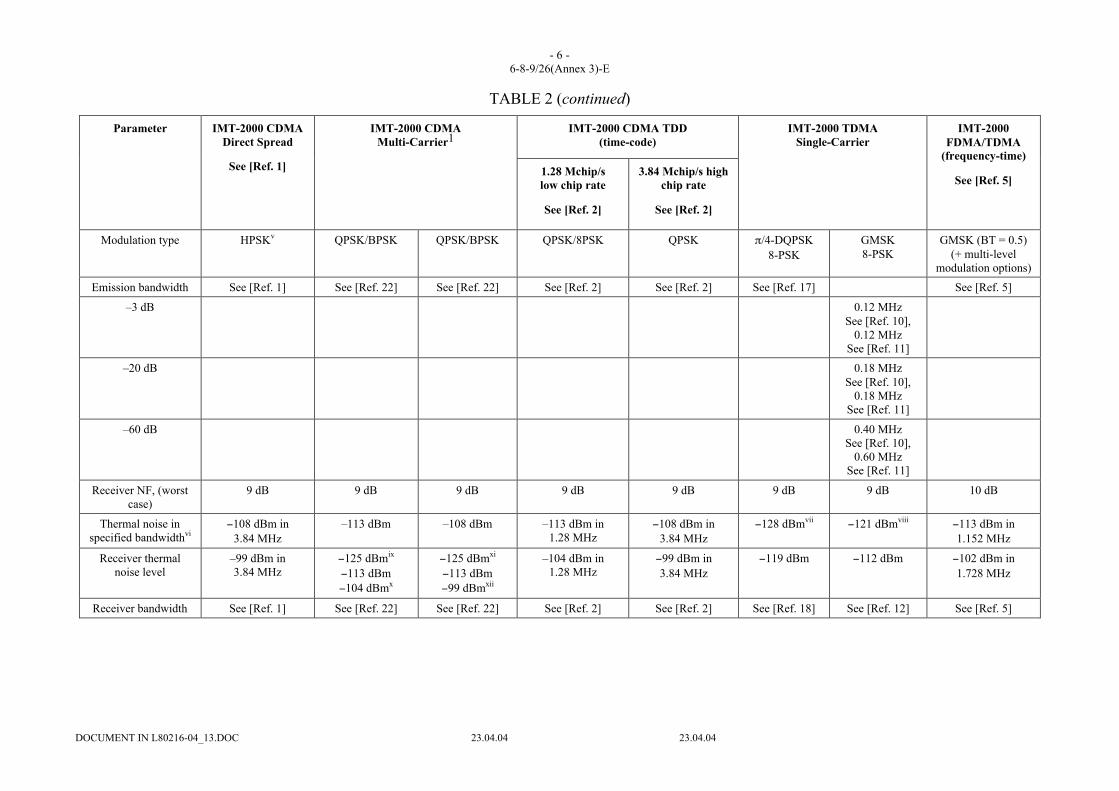
TABLE 2 (continued)
IMT-2000 CDMA TDD(time-code)
Parameter IMT-2000 CDMADirect Spread
See [Ref. 1]
IMT-2000 CDMAMulti-Carrier1
1.28 Mchip/slow chip rate
See [Ref. 2]
3.84 Mchip/s highchip rate
See [Ref. 2]
IMT-2000 TDMASingle-Carrier
IMT-2000FDMA/TDMA
(frequency-time)
See [Ref. 5]
Modulation type HPSKv QPSK/BPSK QPSK/BPSK QPSK/8PSK QPSK π/4-DQPSK8-PSK
GMSK8-PSK
GMSK (BT = 0.5)(+ multi-level
modulation options)
Emission bandwidth See [Ref. 1] See [Ref. 22] See [Ref. 22] See [Ref. 2] See [Ref. 2] See [Ref. 17] See [Ref. 5]
–3 dB 0.12 MHzSee [Ref. 10],
0.12 MHzSee [Ref. 11]
–20 dB 0.18 MHzSee [Ref. 10],
0.18 MHzSee [Ref. 11]
–60 dB 0.40 MHzSee [Ref. 10],
0.60 MHzSee [Ref. 11]
Receiver NF, (worstcase)
9 dB 9 dB 9 dB 9 dB 9 dB 9 dB 9 dB 10 dB
Thermal noise inspecified bandwidthvi
−108 dBm in3.84 MHz
–113 dBm –108 dBm –113 dBm in1.28 MHz
−108 dBm in3.84 MHz
−128 dBmvii −121 dBmviii −113 dBm in1.152 MHz
Receiver thermalnoise level
–99 dBm in3.84 MHz
−125 dBmix
−113 dBm−104 dBmx
−125 dBmxi
−113 dBm−99 dBmxii
–104 dBm in1.28 MHz
−99 dBm in3.84 MHz
−119 dBm −112 dBm −102 dBm in1.728 MHz
Receiver bandwidth See [Ref. 1] See [Ref. 22] See [Ref. 22] See [Ref. 2] See [Ref. 2] See [Ref. 18] See [Ref. 12] See [Ref. 5]

- 7 -6-8-9/26(Annex 3)-E
DOCUMENT IN L80216-04_13.DOC 23.04.04 23.04.04
TABLE 2 (continued)
IMT-2000 CDMA TDD(time-code)
Parameter IMT-2000 CDMADirect Spread
See [Ref. 1]
IMT-2000 CDMAMulti-Carrier1
1.28 Mchip/slow chip rate
See [Ref. 2]
3.84 Mchip/shigh chip rate
See [Ref. 2]
IMT-2000 TDMASingle-Carrier
IMT-2000FDMA/TDMA
(frequency-time)
See [Ref. 5]
–3 dB
–20 dB
–60 dB
Eb/No for Pe = 10−3 See [Ref. 22] Performance notavailable
7.8 dB 8.4 dB 11 dB (non-coherentdetection)
Receiver referencesensitivityxiii
Îor
−117 dBm in3.84 MHz
−104 dBm totalreceived power in
fully loadedsystem. Single
9 600 bit/s trafficchannel is at
–119.6 dBm inAWGN for 0.5%
FER
−99 dBm totalreceived power in
fully loadedsystem
Single 9 600 bit/straffic channel isat –119.6 dBm inAWGN for 0.5%
FER
–108 dBm in1.28 MHz
−105 dBm in3.84 MHz
−113 dBm See[Ref. 19]
−102 dBm See[Ref. 9]
–94 dBm typical(spec.: –86 dBm forspeech and generally
−83 dBm)
Interferencethresholdxiv
−105 dBm in3.84 MHz
−110 dBm in1.25 MHz
−105 dBm in3.75 MHz
–110 dBm in1.28 MHz
−105 dBm in3.84 MHz
No equivalent See [Ref. 13] −105 dBm typical(–97 dBm for
specification speech)
Transmitter ACLR See [Ref. 1] See [Ref. 22]xv See [Ref. 22]xvi See [Ref. 2] See [Ref. 2] See [Ref. 5]
1st adjacent channel 33 dB@ ± 5 MHz
31.6 dB@ ± 3.75 MHz
–33 dBc in3.84 MHz
@ ± 3.08 MHz
33 dB@ ± 1.6 MHz
33 dB@ ± 5 MHz
2nd adjacentchannel
43 dB@ ± 10 MHz
48.2 dB@ ± 8.75 MHz
–43 dBc in3.84 MHz
@ ± 8.08 MHz
43 dB@ ± 3.2 MHz
43 dB@ ± 10 MHz

- 8 -6-8-9/26(Annex 3)-E
DOCUMENT IN L80216-04_13.DOC 23.04.04 23.04.04
TABLE 2 (end)
IMT-2000 CDMA TDD(time-code)
Parameter IMT-2000 CDMADirect Spread
See [Ref. 1]
IMT-2000 CDMAMulti-Carrier1
1.28 Mchip/slow chip rate
See [Ref. 2]
3.84 Mchip/s highchip rate
See [Ref. 2]
IMT-2000 TDMASingle-Carrier
IMT-2000FDMA/TDMA
(frequency-time)
See [Ref. 5]
Transmitter spuriousemissions
See [Ref. 1] See [Ref. 22] See [Ref. 22] See [Ref. 2] See [Ref. 2] See [Ref. 5]
Receiver ACS 33 dB 64 dBxvii 50 dB 33 dB 33 dB
Receiver blockinglevels
See [Ref. 1] See [Ref. 22] See [Ref. 22] See [Ref. 2] See [Ref. 2] See [Ref. 5]
1 The IMT-2000 minimum performance requirements recorded here for IMT-2000 CDMA multicarrier are defined in the band class 6 (i.e. 2 GHz band) requirements in [Ref. 22]. This is alsorelevant to the technology enhancements (HRPD) requirements contained in [Ref. 24].
i May not be appropriate for all scenarios, for example when calculating aggregate interference from all users in a cell.
ii TDMA, comprising 8 timeslots (577 µs) per single TDMA frame (4.615 ms). For user packet data service, 1-4 timeslots per frame may be used by mobile stations having multi-slot classesthat do not require simultaneous transmission and reception, i.e. classes for which a duplexer is not required.
iii Desired signal at sensitivity, I/N = −6 dB for a 10% loss in range applicable to cases where interference effects a limited number of cells. In other cases, e.g. international coordination withBSS sound in the 2.5 GHz band a trigger value of I/N = −10 dB is appropriate.
iv Ten frequency channels with 24 time slots (32 kbit/s) per frame. The frame length is 10 ms.
v Hybrid Phase Shift Keying: a method peculiar to IMT-2000 CDMA Direct Spread in which the peak to average ratio is reduced in comparison to a QPSK signal by mixing the orthogonalvariable spreading factor (OSVF) with both information sources as real signals, i.e. those destined for I and Q modulation components, and then shifting one component by 90 degrees toproduce an equivalent imaginary signal and then utilizing gain control on the Q channel to preserve orthogonality.
vi 10Log(kTb) + 30 (dBm), where k = Boltzman’s constant = 1.38e-23, T = reference temperature = average Earth temperature = 277 K, b = noise equivalent bandwidth (Hz).
vii In the receiver bandwidth.
viii In the receiver bandwidth.
ix In bandwidth equal to data rate: for IMT-2000 CDMA multicarrier, values are given for 9 600 bit/s speech services and nominal supported rate (153.6 kbit/s) for data services.
x In the receiver bandwidth.
xi In bandwidth equal to data rate: for IMT-2000 CDMA multicarrier, values are given for 9 600 bit/s speech services and nominal supported rate (153.6 kbit/s) for data services.
xii In the receiver bandwidth.

- 9 -6-8-9/26(Annex 3)-E
DOCUMENT IN L80216-04_13.DOC 23.04.04 23.04.04
xiii For a 10−3 raw bit error rate, Îor, the received power spectral density (integrated in a bandwidth of (1 + _) times the chip rate and normalized to the chip rate) of the downlink signal asmeasured at the UE antenna connector.
xiv I/N = −6 dB for a 10% loss in range applicable to cases where interference effects a limited number of cells. In other cases, e.g. sharing with BSS (sound) in the 2 630-2 655 MHz band, avalue of I/N = –10 dB is appropriate.
xv Currently [Ref. 22], [Ref. 23] and [Ref. 24] do not contain explicit 1X mobile station or base station ACLR requirements. Nevertheless, the 1X spectrum emission limits described in[Ref. 22] already provide protection of adjacent channels. A lower bound for the effective ACLR can be calculated by integrating the maximum allowed 1X emissions over a 3.84 MHzintegration bandwidth centred at the specified frequency offset are considered. Results summarized in this Table are calculated by assuming a 24 dBm mobile station output power, and aone 43 dBm output power base station. The actual 1X ACLR value in practical implementations will be considerably better since the emission limits (i.e. flat mask, no slope) in the regionof the second adjacent channel do not realistically model a power amplifier emissions roll-off.
xvi The requirements at offsets of 3.08 and 8.08 MHz are equivalent to ACLR requirements of 33 and 43 dB from a 3X mobile station transmitter into a 3X or IMT-DS mobile stationreceiver offset by 5 and 10 MHz respectively. With regard to base stations, [Ref. 21] currently does not contain an explicit ACLR requirement for base stations. Nevertheless, the 1Xspectrum emission limits described in [Ref. 21] already provide protection of adjacent channels. A lower bound for the effective ACLR can be calculated by integrating the maximumallowed emissions of three neighbouring IMT-MC 1x channels over a 3.84 MHz integration bandwidth centred at the specified frequency offset. Results summarized in this Table areproduced assuming three adjacent 38 dBm output power 1X base stations; the aggregate output power over the 5 MHz of assigned channels is 43 dBm.
xvii The test equipment ACLR (i.e. in-band emissions contributions) effectively limits the mobile station ACS that can be tested.
- 10 -6-8-9/26(Annex 3)-E
DOCUMENT IN L80216-04_13.DOC 23.04.04 23.04.04
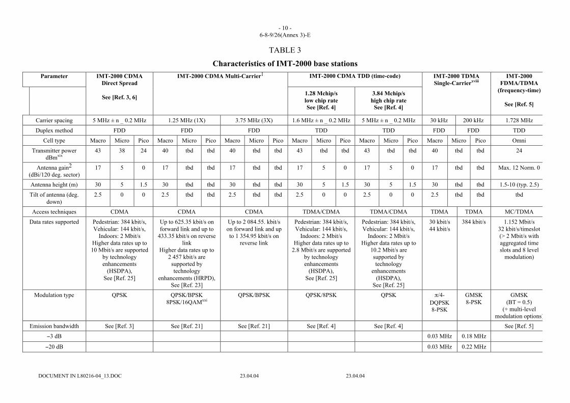
TABLE 3
Characteristics of IMT-2000 base stations
Parameter IMT-2000 CDMA TDD (time-code)IMT-2000 CDMADirect Spread
See [Ref. 3, 6]
IMT-2000 CDMA Multi-Carrier1
1.28 Mchip/slow chip rateSee [Ref. 4]
3.84 Mchip/shigh chip rate
See [Ref. 4]
IMT-2000 TDMASingle-Carrierxviii
IMT-2000FDMA/TDMA
(frequency-time)
See [Ref. 5]
Carrier spacing 5 MHz ± n _ 0.2 MHz 1.25 MHz (1X) 3.75 MHz (3X) 1.6 MHz ± n _ 0.2 MHz 5 MHz ± n _ 0.2 MHz 30 kHz 200 kHz 1.728 MHz
Duplex method FDD FDD FDD TDD TDD FDD FDD TDD
Cell type Macro Micro Pico Macro Micro Pico Macro Micro Pico Macro Micro Pico Macro Micro Pico Macro Micro Pico Omni
Transmitter powerdBmxix
43 38 24 40 tbd tbd 40 tbd tbd 43 tbd tbd 43 tbd tbd 40 tbd tbd 24
Antenna gain2
(dBi/120 deg. sector)17 5 0 17 tbd tbd 17 tbd tbd 17 5 0 17 5 0 17 tbd tbd Max. 12 Norm. 0
Antenna height (m) 30 5 1.5 30 tbd tbd 30 tbd tbd 30 5 1.5 30 5 1.5 30 tbd tbd 1.5-10 (typ. 2.5)
Tilt of antenna (deg.down)
2.5 0 0 2.5 tbd tbd 2.5 tbd tbd 2.5 0 0 2.5 0 0 2.5 tbd tbd tbd
Access techniques CDMA CDMA CDMA TDMA/CDMA TDMA/CDMA TDMA TDMA MC/TDMA
Data rates supported Pedestrian: 384 kbit/s,Vehicular: 144 kbit/s,
Indoors: 2 Mbit/sHigher data rates up to10 Mbit/s are supported
by technologyenhancements
(HSDPA),See [Ref. 25]
Up to 625.35 kbit/s onforward link and up to
433.35 kbit/s on reverselink
Higher data rates up to2 457 kbit/s are
supported bytechnology
enhancements (HRPD),See [Ref. 23]
Up to 2 084.55. kbit/son forward link and upto 1 354.95 kbit/s on
reverse link
Pedestrian: 384 kbit/s,Vehicular: 144 kbit/s,
Indoors: 2 Mbit/sHigher data rates up to
2.8 Mbit/s are supportedby technologyenhancements
(HSDPA),See [Ref. 25]
Pedestrian: 384 kbit/s,Vehicular: 144 kbit/s,
Indoors: 2 Mbit/sHigher data rates up to
10.2 Mbit/s aresupported bytechnology
enhancements(HSDPA),
See [Ref. 25]
30 kbit/s44 kbit/s
384 kbit/s 1.152 Mbit/s32 kbit/s/timeslot(> 2 Mbit/s withaggregated timeslots and 8 level
modulation)
Modulation type QPSK QPSK/BPSK8PSK/16QAMxxi
QPSK/BPSK QPSK/8PSK QPSK π/4-DQPSK8-PSK
GMSK8-PSK
GMSK(BT = 0.5)
(+ multi-levelmodulation options)
Emission bandwidth See [Ref. 3] See [Ref. 21] See [Ref. 21] See [Ref. 4] See [Ref. 4] See [Ref. 5]
−3 dB 0.03 MHz 0.18 MHz
−20 dB 0.03 MHz 0.22 MHz

- 11 -6-8-9/26(Annex 3)-E
DOCUMENT IN L80216-04_13.DOC 23.04.04 23.04.04
TABLE 3 (continued)
IMT-2000 CDMA TDD(time-code)
Parameter IMT-2000 CDMADirect Spread
See [Ref. 3, 6]
IMT-2000 CDMA Multi-Carrier1
1.28 Mchip/slow chip rateSee [Ref. 4]
3.84 Mchip/shigh chip rate
See [Ref. 4]
IMT-2000 TDMASingle-Carrierxviii
IMT-2000FDMA/TDMA
(frequency-time)
See [Ref. 5]
−60 dB 0.04 MHz 0.24 MHz
Receiver noisefigure (worst case)
5 dB for macro BS 5 dB 5 dB 7 dB for macro BS 5 dB for macro BS 5 dB 5 dB 10 dB
Receiver thermalnoise level
−103 dBm in 3.84MHz for macro BS
−129 dBm−117 dBmxxii
−108 dBmxxiii
−129 dBm−117 dBmxxiv
−103 dBmxxv
−106 dBm in 1.28MHz for macro BS
−103 dBm in 3.84MHz for macro BS
−125 dBmxxvi −117 dBmxxvii −103 dBm in1.152 MHz
Receiverbandwidth
< 5 MHz (See [Ref. 3]) See [Ref. 21] See [Ref. 21] < 1.6 MHz(See [Ref. 4])
< 5 MHz (See [Ref. 4]) See [Ref. 5]
−3 dB 0.03 MHz 0.18 MHz
−20 dB 0.04 MHz 0.25 MHz
−60 dB 0.09 MHz 0.58 MHz
Eb/No for Pe = 10−3 See [Ref. 3] See [Ref. 21] performance notavailable
7.8 dB 8.4 dB 11 dB (non-coherent detection)
Receiver referencesensitivityxxviii
−121 dBmxxix formacro BS
–111 dBm formicro BS
–107 dBm for pico BS
−119 dBm forfundamental channel in
AWGN
−119 dBm forfundamental channel in
AWGN
–110 dBm for macroand micro BS
–96 dBm for pico BS
−109 dBm for macroand micro BS
–95 dBm for pico BS
−117 dBm −108 dBm −94 typical(spec.: –86 dBmfor speech and
generally−83 dBm)
Interferencethreshold for
macro BS 1xxx
−109 dBm in3.84 MHz See notexxxi
−114 dBm in1.25 MHz
−109 dBm in3.75 MHz
–112 dBm in 1.28MHz
−109 dBm in3.84 MHz
−131 dBm −123 dBm −105 dBm typical(−97 dBm for
speech specificat.)
Transmitter ACLRfor macro/micro/
pico BS
See [Ref. 3, 6] See [Ref. 21]xv See [Ref. 21]xvi See [Ref. 4] See [Ref. 4]
1st adjacent 45 dB@ ± 5 MHz
50.8 dB@ ± 3.75 MHz
49.3 dB@ ± 5 MHz
40 dB@ ± 1.6 MHz
45 dB@ ± 5 MHz
2nd adjacent 50 dB@ ± 10 MHz
67.2 dB@ ± 8.75 MHz
62.2 dB@ ± 10 MHz
45 dB@ ± 3.2 MHz
55 dB@ ± 10 MHz
Transmitterspurious emissions
See [Ref. 3, 6] See [Ref. 21] See [Ref. 21] See [Ref. 4] See [Ref. 4]
Macro BS receiverACS (relative
ACS)
−52 dBm(46 dB)xxxi
–53 dBm –49 dBm −55 dBm(46 dB)xxxi
−52 dBm(46 dB)xxxi

- 12 -6-8-9/26(Annex 3)-E
DOCUMENT IN L80216-04_13.DOC 23.04.04 23.04.04
IMT-2000 CDMA TDD(time-code)
Parameter IMT-2000 CDMADirect Spread
See [Ref. 3, 6]
IMT-2000 CDMA Multi-Carrier1
1.28 Mchip/slow chip rateSee [Ref. 4]
3.84 Mchip/shigh chip rate
See [Ref. 4]
IMT-2000 TDMASingle-Carrierxviii
IMT-2000FDMA/TDMA
(frequency-time)
See [Ref. 5]
ACS)

- 13 -6-8-9/26(Annex 3)-E
DOCUMENT IN L80216-04_13.DOC 23.04.04 23.04.04
TABLE 3 (end)IMT-2000 CDMA TDD
(time-code)Parameter IMT-2000 CDMA
Direct SpreadSee [Ref. 3, 6]
IMT-2000 CDMA Multi-Carrier1
1.28 Mchip/slow chip rateSee [Ref. 4]
(3.84 Mchip/shigh chip rate)
See [Ref. 4]
IMT-2000 TDMASingle-Carrierxviii
IMT-2000FDMA/TDMA
(frequency-time)
See [Ref. 5]
Micro BS receiverACS (relative ACS)
−42 dBm(46 dB)xxxi
tbd Tbd −41 dBm(46 dB)xxxi
−38 dBm(46 dB)xxxii
Pico BS receiverACS (relative ACS)
–38 dBm(46 dB)xxxi
tbd Tbd –41 dBm(46 dB)xxxi
−38 dBm(46 dB)xxxi
Receiver blockinglevels
See [Ref. 3, 6] See [Ref. 21] See [Ref. 21] See [Ref. 4] See [Ref. 4]
1 The IMT-2000 minimum performance requirements recorded here for IMT-2000 CDMA multicarrier are defined in the band class 6 (i.e. 2 GHz band) requirements in [Ref. 21]. This is also relevant tothe technology enhancements (HRPD) requirements contained in [Ref. 23].
2 Feeder losses are not included in the values and should be considered in the sharing/compatibility issues.xviii IMT-2000 TDMA single carrier consists of three components: enhancements to the 30 kHz channels (designated as 136+) for advanced voice and data capabilities, a 200 kHz carrier component for
high speed data (384 kbit/s) accommodating high mobility (designated as 136HS outdoor), and a 1.6 MHz carrier component for very high speed data (2 Mbit/s) in low mobility applications (designatedas 136HS indoor). The combined result constitutes the IMT-2000 radio interface referred to as IMT-2000 TDMA single carrier.
xix May not be appropriate for all scenarios.xx The reference pattern is specified in Recommendation ITU-R F.1336-1 with (k = 0.2).xxi Both HRPD and IMT-2000 CDMA multicarrier revision C support 8PSK and 16QAM on the forward packet channel.xxii In bandwidth equal to data rate: for IMT-2000 CDMA multicarrier, values are given for 9 600 bit/s speech services and nominal supported rate for data services.xxiii In the receiver bandwidth.xxiv In bandwidth equal to data rate: for IMT-2000 CDMA multicarrier, values are given for 9 600 bit/s speech services and nominal supported rate for data services.xxv In the receiver bandwidth.xxvi In bandwidth equal to data rate: for IMT-2000 CDMA multicarrier, values are given for 9 600 bit/s speech services and nominal supported rate for data services.xxvii In bandwidth equal to data rate: for IMT-2000 CDMA multicarrier, values are given for 9 600 bit/s speech services and nominal supported rate for data services.xxviii For a 10−3 raw bit error rate, theoretical Eb/No.xxix The thermal noise figure for a WCDMA receiver is –108 dBm based on kTf where k is Boltzmann’s constant (1.38E-23), T is the temperature in Kelvin, and f is the bandwidth in Hertz. For a noise
figure of 4 dB (typical value for a base station receiver), the thermal noise becomes –104 dBm. However, receiver sensitivity depends on the service (i.e. voice, packet, etc.). For example, the voice(DTCH 32) sensitivity for the base station receiver is –121 dBm for BER < 0.001.
xxx I/N = −6 dB for a 10% loss in range applicable to cases where interference effects a limited number of cells. In other cases, e.g. sharing with BSS (sound) in the 2 630-2 655 MHz band a value ofI/N = –10 dB is appropriate.
xxxi The tolerable I/N thresholds are as follows: coordinated use (–6 dB), agreement trigger (–10 dB), licence exempt (–20 dB).xxxii The absolute ACS values are the test values as specified in 3GPP TS25.104 and TS 25.105. The following conversion formula: ACS_relative = ACS_test – Noise_floor – 10*log10(10M/10–1), can be
used to derive relative ACS values, Where M is the margin expressed in dB used in the ACS test, which is the useful signal level above the reference sensitivity level. For both IMT-2000 CDMA directspread and IMT-2000 CDMA TDD (time code), M = 6 dB. ACS relative values are often used in sharing studies.

- 14 -6-8-9/26(Annex 3)-E
DOCUMENT IN L80216-04_13.DOC 23.04.04 23.04.04
References (in Tables 2 and 3)
[1] 3GPP TS 25.101 v5.5.0 (2002-12) 3rd Generation Partnership Project; Technical SpecificationGroup Radio Access Networks; “UE Radio Transmission and Reception (FDD) (Release 5)”.
[2] 3GPP TS 25.102 v5.3.0 (2002-12): 3rd Generation Partnership Project; Technical SpecificationGroup Radio Access Networks; “UE Radio Transmission and Reception (TDD) (Release 5)”.
[3] 3GPP TS 25.104 v6.0.0 (2002-12): 3rd Generation Partnership Project; Technical SpecificationGroup Radio Access Networks; “BS Radio Transmission and Reception (FDD) (Release 6)”.
[4] 3GPP TS 25.105 v5.3.0 (2002-12): 3rd Generation Partnership Project; Technical SpecificationGroup Radio Access Networks; “BS Radio Transmission and Reception (TDD) (Release 5)”.
[5] Final Draft ETSI EN 300 175-2 v1.6.0 (2001-04): “Digital Enhanced Telecommunications (DECT)Common Interface (CI) part 2: Physical Layer”.
[6] 3GPP TR 25.951 v1.5.0 (2003-02): 3rd Generation Partnership Project; Technical SpecificationGroup Radio Access Networks, “FDD Base Station Classification (Release 6)”.
[7] TR45 technical specification, TIA/EIA-136-290); “RF Minimum performance requirements 136HSOutdoor and 136HS Indoor Bearers”, clause 2.
[8] TR45 technical specification, TIA/EIA-136-290; “RF Minimum performance requirements 136HSOutdoor and 136HS Indoor Bearers”, clause 4.1.1.2 refers to Power Class II mobile station.
[9] TR45 technical specification, TIA/EIA-136-290; “RF Minimum performance requirements 136HSOutdoor and 136HS Indoor Bearers”, clause 6.2 specifies data rates and reference sensitivity.Reference sensitivity listed for 144 kbit/s at a 10% block erasure rate (BLER).
[10] TR45 technical specification, TIA/EIA-136-290; “RF Minimum performance requirements 136HSOutdoor and 136HS Indoor Bearers”, Table A3a: Modulation and noise spectrum mask due toGMSK modulation. Measurement bandwidth is 30 kHz.
[11] TR45 technical specification, TIA/EIA-136-290; “RF Minimum performance requirements 136HSOutdoor and 136HS Indoor Bearers”, Table A3b: Modulation and noise spectrum mask due to8-PSK modulation. Measurement bandwidth is 30 kHz.
[12] TR45 technical specification, TIA/EIA-136-290; “RF Minimum performance requirements 136HSOutdoor and 136HS Indoor Bearers”, clause 5.1:
[13] TR45 technical specification, TIA/EIA-136-290; “RF Minimum performance requirements 136HSOutdoor and 136HS Indoor Bearers”, clause 6.3:
[14] TR45 technical specification, SP-4027-270b); “Mobile Station Minimum Performance”,Clause 2.3.1.3.1.
[15] TR45 technical specification, SP-4027-270b); “Mobile Station Minimum Performance”, Clause 1.4and Clause 3.2.2. Refers To Power Class Ii Mobile Station.
[16] TR45 technical specification, TIA/EIA 136-131; “Digital Traffic Channel Layer 1”, Clause 1.3.
[17] TR45 technical specification, SP-4027-270b; “Mobile Station Minimum Performance”,Clause 3.4.1.1.3.
[18] TR45 technical specification, SP-4027-270b; “Mobile Station Minimum Performance”,Clause 2.3.2.4.3:
[19] TR45 technical specification, SP-4027-270b; “Mobile Station Minimum Performance”,Clause 2.3.1.1.3.
[20] 3GPP TS 25.942; 3rd Generation Partnership Project; Technical Specification Group Radio AccessNetworks; “RF System Scenarios”, clause 4.1.1.2. Body loss expectation is that values are similarfor all technologies. Footnote retained for information purposes.
[21] TR45 technical specification, TIA-97-E; “Recommended minimum performance Standards forcdma2000® spread spectrum base stations”.

- 15 -6-8-9/26(Annex 3)-E
DOCUMENT IN L80216-04_13.DOC 23.04.04 23.04.04
[22] TR45 technical specification, TIA-98-E; “Recommended minimum performance Standards forcdma2000® spread spectrum mobile stations”.
[23] TR45 technical specification, TIA-864-E; “Recommended minimum performance Standards forcdma2000® High Rate Packet Data Access Network”.
[24] TR45 technical specification, TIA-866-E; “Recommended minimum performance Standards forcdma2000® High Rate Packet Data Access Terminal”.
[25] 3GPP TS 25.308 v5.4.0 (2003-03); 3rd Generation Partnership Project; Technical SpecificationGroup Radio Access Network; “High Speed Downlink Packet Access (HSDPA); Overalldescription; Stage 2 (Release 5)”.
IMT-2000 Characteristics (Source: Doc 20 (Canada))
IMT-2000 Mobile Station Characteristics
Maximum Noise Figure 9 dB
Noise Floor -135 dB(W/MHz)
Antenna Gain 0 dBi
Polarization Linear
I/N to be used as a trigger value for sharingstudies
-10 dB
IMT-2000 Base Station Characteristics
Typical Noise Figure 5 dB
Noise Floor -139 dB(W/MHz)
Feeder Loss 2 dB
Polarization Linear
Typical Antenna 120° Sector
Maximum Antenna Gain 18 dBi
Down-tilt Angle 2.5°
I/N to be used as a trigger value for sharingstudies
-10 dB

- 16 -6-8-9/26(Annex 3)-E
DOCUMENT IN L80216-04_13.DOC 23.04.04 23.04.04
3 Equipment characteristics for non-IMT-2000 mobile systems (Source: Doc 13 (USA))
Non-IMT-2000 mobile base station characteristics
Non-IMT-2000 mobile base station receive parameters
Cell size (km radius) 3-10
Antenna type 120˚ sector
Max antenna gain (dBi) includingfeeder loss
18
Downtilt angle (˚) 1
Antenna height (m) HAAT 50
Polarization Linear
Receiver noise figure (dB) 3
Receiver thermal noise (dBW/MHz) –141
Trigger for Sharing Studies(Isat/Nth) (dB)
-10
ACS FDD: varies *TDD: varies *
*Varies by supplier
TABLE 3.1.2
Non-IMT-2000 mobile base station transmit parameters
Cell size (km radius) 3-10Maximum transmit power fora 5 MHz channel (dBm)(standards)
47
Typical transmit power for a5 MHz channel (dBm)
43
Operating bandwidth (MHz) 5-6Antenna type 120˚ sectorMax antenna gain (dBi)including feeder loss
18
Downtilt angle (˚) 1Antenna height (m) HAAT 50Polarization Linear
- 17 -6-8-9/26(Annex 3)-E
DOCUMENT IN L80216-04_13.DOC 23.04.04 23.04.04
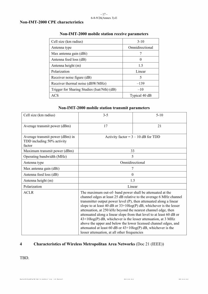
Non-IMT-2000 CPE characteristics
Non-IMT-2000 mobile station receive parameters
Cell size (km radius) 3-10
Antenna type Omnidirectional
Max antenna gain (dBi) 7
Antenna feed loss (dB) 0
Antenna height (m) 1.5
Polarization Linear
Receiver noise figure (dB) 5
Receiver thermal noise (dBW/MHz) –139
Trigger for Sharing Studies (Isat/Nth) (dB) –10
ACS Typical 40 dB
Non-IMT-2000 mobile station transmit parameters
Cell size (km radius) 3-5 5-10
Average transmit power (dBm) 17 21
Average transmit power (dBm) inTDD including 50% activityfactor
Activity factor = 3 – 10 dB for TDD
Maximum transmit power (dBm) 33
Operating bandwidth (MHz) 5
Antenna type Omnidirectional
Max antenna gain (dBi) 7
Antenna feed loss (dB) 0
Antenna height (m) 1.5
Polarization Linear
ACLR The maximum out-of- band power shall be attenuated at thechannel edges at least 25 dB relative to the average 6 MHz channeltransmitter output power level (P), then attenuated along a linearslope to at least 40 dB or 33+10log(P) dB, whichever is the lesserattenuation, at 250 kHz beyond the nearest channel edge, thenattenuated along a linear slope from that level to at least 60 dB or43+10log(P) dB, whichever is the lesser attenuation, at 3 MHzabove the upper and below the lower licensed channel edges, andattenuated at least 60 dB or 43+10log(P) dB, whichever is thelesser attenuation, at all other frequencies
4 Characteristics of Wireless Metropolitan Area Networks (Doc 21 (IEEE))
TBD.