Embed Size (px)
Citation preview
161© Ernst & Sohn Verlag für Architektur und technische Wissenschaften GmbH & Co. KG, Berlin · Steel Construction 2 (2009), No. 3
1 Introduction
After the Great Hanshin Earthquakethe number of base isolation applica-tions increased dramatically in Japan.Various structures with base isolationcan now be seen, e.g. hospitals, houses,bridges, even high-rise buildings. Nor-mally, those structures are speciallydesigned with enhanced resistanceagainst overturning so that tensiondoes not occur in isolator bearings.Depending upon the profile, thestrength of the seismic force or thedistance from the active fault, how-ever, there is a possibility that isolatorsmight be subjected to tension. Thelaminated rubber bearing that is mostoften used as an isolator in Japan isnow designed to sustain structuresunder some tension because it is ac-
other materials (carbon black filler,vulcanizing agent, or oil) and apply-ing heat and pressure, the molecularchains are connected to each other.The rubber then finally acquires itselastic property. There are two types ofrubber that are used for the laminatedelastomeric bearing. One is naturalrubber, which has an almost linearelastic behaviour and a superior creepresistance. However, it should not beexposed to the atmosphere becauseozone deteriorates this type of rubber.The other is high damping rubber,which is made from petroleum andexhibits non-linear behaviour, and itscharacteristics can be modified forspecific purposes by changing the ra-tio of the materials.
Rubber undergoes a molecularchange during deformation. As themolecular chains become more andmore parallel, it reaches the crystal-lization through which an increase inthe shear modulus and reinforcementof the net-like structure are obtained.This phase is still reversible; hence,when it is unloaded the material struc-ture returns to its irregular amorphouscondition. Further deformation stabi-lizes its crystal lattice and then thematerial reaches plasticity. Moreover,rubber materials exhibit a reductionin stiffness during the first few cyclesof cyclic loading. This phenomenon isgenerally referred to as the Mullinseffect. This mechanism is still not en-tirely clear, yet it is known to be relatedto the breakdown of the cross-linkingor the separation of the weak bond be-tween filler particles and long chains[1].
Shear stiffness increases whenthe compression is applied simulta-neously. This phenomenon dependson the shape factor. If the shape fac-tor (SF = loaded surface area/ free
Ingbert Mangerig*Toshihisa Mano
Characteristics of various elastomeric bearings in tensionIt has been a long time since seismic isolation was invented with the aim of protecting livesand structures against earthquakes. Seismic isolation is achieved by installing special bear-ings, so-called isolators, between the foundations of buildings or the piers of bridges and thesuperstructure. These isolators support the structure in the vertical direction and at thesame time allow horizontal movements during earthquakes so that the seismic force appliedto the superstructure can be much reduced. In Japan elastomeric bearings are often usedfor this purpose and existing seismic-isolated structures have demonstrated their effective-ness in the past. A number of research projects concerning elastomeric bearings have beencarried out and their performance with respect to compression and shear loads is well un-derstood. However, not much attention has been paid to their characteristics with respect totensile loads. In some design standards a certain degree of tension in rubber bearings is al-ready allowed to occur during earthquakes. This is inevitable since the ability of rubber tosustain tension was discovered and in seismic isolation applications in high-rise buildingsand bridges there is a possibility that isolators undergo tension due to the overturning mo-ment. There are, however, still many uncertainties; for instance, the influence of damage toor cavities within the rubber caused by tension, the interaction between the shapes and di-mensions of bearings and the tensile strength, and the influence of the out-of-plane defor-mation of flanges are not well understood. Currently, the Japanese design rules for bothbridges and buildings regulate the allowable tensile stress without distinguishing the type ofrubber, shapes or dimensions. This merely empirical value will need to be reconsidered.
Articles
knowledged that the rubber materialcan resist tension to a certain degree.If rubber is subjected to tension, cavi-ties (called “voids” in some literature)develop that may deteriorate its per-formance. Various research projectsregarding this aspect have been car-ried out, yet it did not seem to attractenough attention. Furthermore, eachof those studies concerns mainly aspecific type of material or shape. As aresult it is still not clear which factoris most influential for cavity propaga-tion or the change in the characteris-tics after cavities develop. In the follow-ing those research results are collectedand summarized in order to graspcomprehensibly the cavity propaga-tion mechanism and its influence onthe performance of elastomeric bear-ings.
2 Rubber characteristics
Rubber is a polymer material. By vul-canizing and mixing it with some
DOI: 10.1002/stco.200910020
Received 14 May 2009, accepted 25 June 2009* Corresponding author:[email protected]
surface area) is higher, then the inter-nal change in the material structure issmaller. Therefore, its influence onstrength and material damping islessened as well.
Rubber exhibits a considerablechange in stiffness at higher loadingspeeds. The faster the speed of loadapplication, the higher the stiffnessbecomes. This effect is normally smallin the case of a small strain ratio.
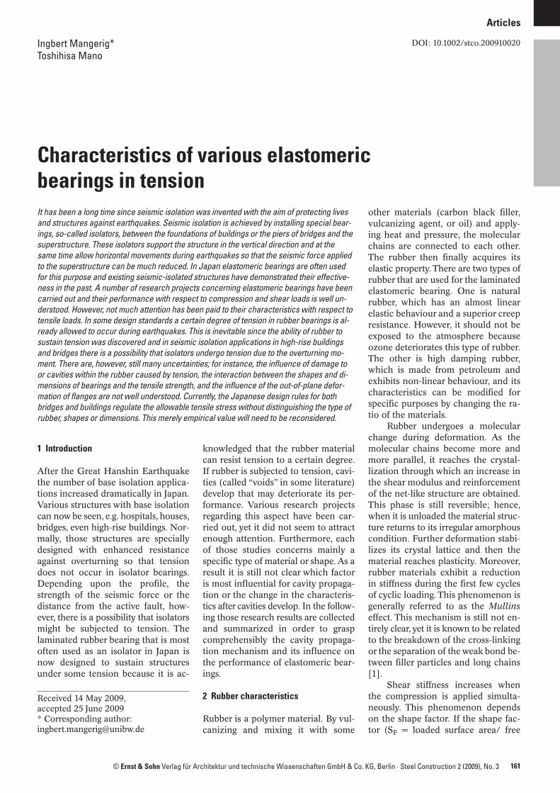
In the context of the tensile re-sistance of the rubber, one importantaspect is the development of cavities.This happens where the high hydro-static stress occurs. Therefore, whenan elastomeric bearing without a cen-tral hole is considered, those cavitiesare assumed to occur at the centre ofthe rubber disk and some experi-ments have confirmed this. Fig. 1shows the deformed shape of a rub-ber disk with the stress state at theedge and at the centre.
Pond [3] observed the cavitationprocess mechanism by way of a seriesof cyclic tensile loading tests. Two kindsof compounds were prepared. One was
162 Steel Construction 2 (2009), No. 3
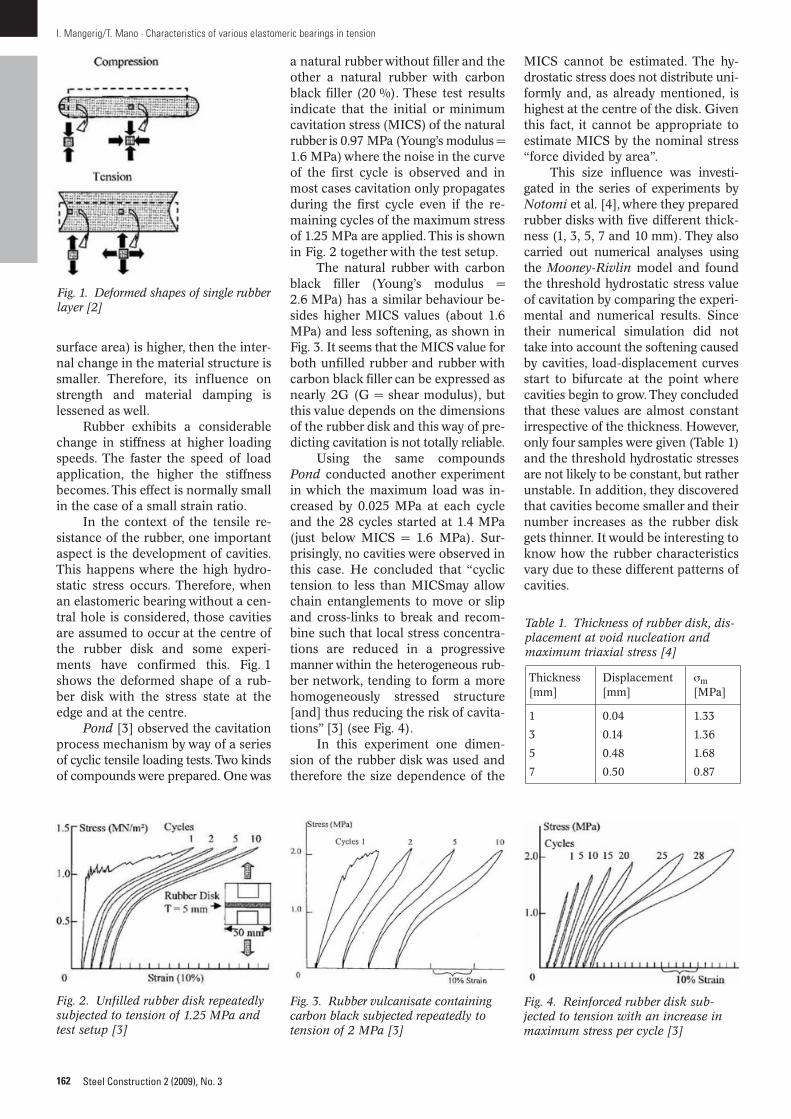
a natural rubber without filler and theother a natural rubber with carbonblack filler (20 %). These test resultsindicate that the initial or minimumcavitation stress (MICS) of the naturalrubber is 0.97 MPa (Young’s modulus =1.6 MPa) where the noise in the curveof the first cycle is observed and inmost cases cavitation only propagatesduring the first cycle even if the re-maining cycles of the maximum stressof 1.25 MPa are applied. This is shownin Fig. 2 together with the test setup.
The natural rubber with carbonblack filler (Young’s modulus =2.6 MPa) has a similar behaviour be-sides higher MICS values (about 1.6MPa) and less softening, as shown inFig. 3. It seems that the MICS value forboth unfilled rubber and rubber withcarbon black filler can be expressed asnearly 2G (G = shear modulus), butthis value depends on the dimensionsof the rubber disk and this way of pre-dicting cavitation is not totally reliable.
Using the same compoundsPond conducted another experimentin which the maximum load was in-creased by 0.025 MPa at each cycleand the 28 cycles started at 1.4 MPa(just below MICS = 1.6 MPa). Sur-prisingly, no cavities were observed inthis case. He concluded that “cyclictension to less than MICSmay allowchain entanglements to move or slipand cross-links to break and recom-bine such that local stress concentra-tions are reduced in a progressivemanner within the heterogeneous rub-ber network, tending to form a morehomogeneously stressed structure[and] thus reducing the risk of cavita-tions” [3] (see Fig. 4).
In this experiment one dimen-sion of the rubber disk was used andtherefore the size dependence of the
MICS cannot be estimated. The hy-drostatic stress does not distribute uni-formly and, as already mentioned, ishighest at the centre of the disk. Giventhis fact, it cannot be appropriate toestimate MICS by the nominal stress“force divided by area”.
This size influence was investi-gated in the series of experiments byNotomi et al. [4], where they preparedrubber disks with five different thick-ness (1, 3, 5, 7 and 10 mm). They alsocarried out numerical analyses usingthe Mooney-Rivlin model and foundthe threshold hydrostatic stress valueof cavitation by comparing the experi-mental and numerical results. Sincetheir numerical simulation did nottake into account the softening causedby cavities, load-displacement curvesstart to bifurcate at the point wherecavities begin to grow. They concludedthat these values are almost constantirrespective of the thickness. However,only four samples were given (Table 1)and the threshold hydrostatic stressesare not likely to be constant, but ratherunstable. In addition, they discoveredthat cavities become smaller and theirnumber increases as the rubber diskgets thinner. It would be interesting toknow how the rubber characteristicsvary due to these different patterns ofcavities.
I. Mangerig/T. Mano · Characteristics of various elastomeric bearings in tension
Fig. 1. Deformed shapes of single rubberlayer [2]
Fig. 2. Unfilled rubber disk repeatedlysubjected to tension of 1.25 MPa andtest setup [3]
Fig. 3. Rubber vulcanisate containingcarbon black subjected repeatedly totension of 2 MPa [3]
Fig. 4. Reinforced rubber disk sub-jected to tension with an increase inmaximum stress per cycle [3]
Table 1. Thickness of rubber disk, dis-placement at void nucleation andmaximum triaxial stress [4]
Thickness Displacement σm[mm] [mm] [MPa]
1 0.04 1.33
3 0.14 1.36
5 0.48 1.68
7 0.50 0.87
163Steel Construction 2 (2009), No. 3
3 How the cavities influence the rubber property
The isolator is mainly subjected tocompression and shear deformationand therefore the influence of thecavities on those properties of rubberis our main interest.
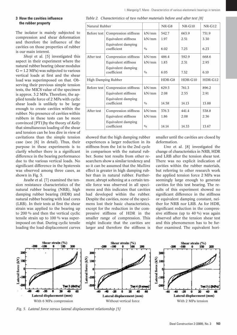
Shoji et al. [5] investigated thisaspect in their experiment where thenatural rubber bearing (shear modulusG = 1.2 MPa) was subjected to variousvertical loads at first and the shearload was superimposed on that. Ob-serving their previous simple tensiontests, the MICS value of the specimenis approx. 3.2 MPa. Therefore, the ap-plied tensile force of 2 MPa with cyclicshear loads is unlikely to be largeenough to create cavities within therubber. No presence of cavities withinrubbers in these tests can be moreconvinced [PT1]by the theory of Kellythat simultaneous loading of the shearand tension can be less dire in view ofcavitations than the simple tensioncase (see [6] in detail). Thus, theirpurpose in these experiments is toclarify whether there is a significantdifference in the bearing performancedue to the various vertical loads. Nosignificant difference in the hysteresiswas observed among three cases, asshown in Fig. 5.
Iwabe et al. [7] examined the ten-sion resistance characteristics of thenatural rubber bearing (NRB), highdamping rubber bearing (HDR) andnatural rubber bearing with lead cores(LRB). In their tests at first the shearstrain was applied to the bearing upto 200 % and then the vertical cyclictensile strain up to 100 % was super-imposed on that. During cyclic tensileloading the load-displacement curves
showed that the high damping rubberexperiences a larger reduction in itsstiffness from the 1st to the 2nd cyclein comparison with the natural rub-ber. Some test results from other re-searchers show a similar tendency andso it can be assumed that the Mullinseffect is greater in high damping rub-ber than in natural rubber. Further-more, abrupt softening at a certain ten-sile force was observed in all speci-mens and this indicates that cavitieshad developed within the rubber.Despite the cavities, none of the speci -mens lost their basic characteristics,except for the reduction in the com-pressive stiffness of HDR in thesmaller range of compression. Thismight indicate that the cavities arelarger and therefore the stiffness is
I. Mangerig/T. Mano · Characteristics of various elastomeric bearings in tension
Fig. 5. Lateral force versus lateral displacement relationship [5]
With 6 MPa compression Without vertical force With 2 MPa tension
smaller until the cavities are closed bydeformation.
Uno et al. [8] investigated thechange of characteristics in NRB, HDRand LRB after the tension shear test.There was no explicit indication ofcavities within the rubber materials,but referring to other research workthe applied tension force 2 MPa wasseemingly large enough to generatecavities for this test bearing. The re-sults of this experiment showed nosignificant difference in the stiffnessor equivalent damping constant, nei-ther for NRB nor LRB. As for HDR,significant reduction in the compres-sive stiffness (up to 40 %) was againobserved after the tension shear testand this phenomenon has to be fur-ther examined. The equivalent hori-
Table 2. Characteristics of two rubber materials before and after test [8]
Natural Rubber NR-G8 NR-G10 NR-G12
Before test Compression stiffness kN/mm 542.7 663.9 751.9
Equivalent stiffness kN/mm 1.97 2.51 3.30
Equivalent damping coefficient % 6.02 7.25 6.23
After test Compression stiffness kN/mm 486.4 592.9 668.6
Equivalent stiffness kN/mm 1.83 2.31 2.95
Equivalent damping coefficient % 6.05 7.32 6.10
High Damping Rubber HDR-G8 HDR-G10 HDR-G12
Before test Compression stiffness kN/mm 629.5 761.3 896.2
Equivalent stiffness kN/mm 2.08 2.55 2.91
Equivalent damping coefficient % 14.58 14.13 13.88
After test Compression stiffness kN/mm 376.3 441.4 538.8
Equivalent stiffness kN/mm 1.86 2.08 2.36
Equivalent damping coefficient % 14.14 14.33 13.67
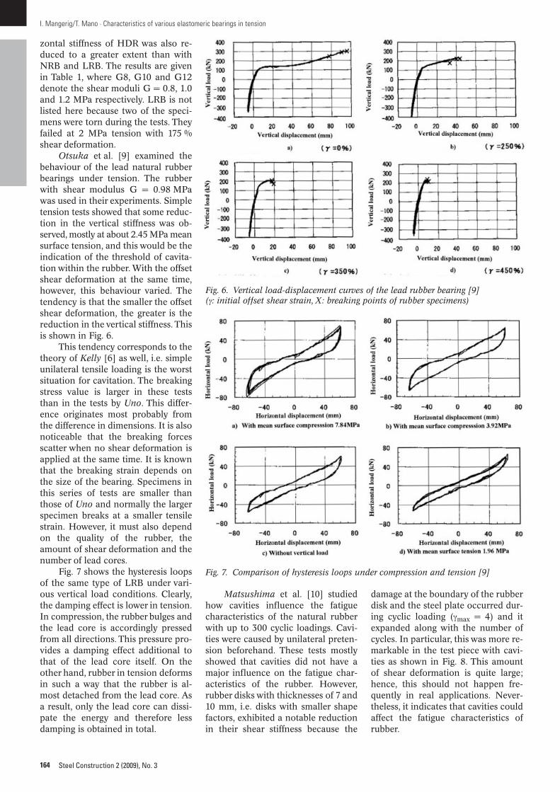
zontal stiffness of HDR was also re-duced to a greater extent than withNRB and LRB. The results are givenin Table 1, where G8, G10 and G12denote the shear moduli G = 0.8, 1.0and 1.2 MPa respectively. LRB is notlisted here because two of the speci-mens were torn during the tests. Theyfailed at 2 MPa tension with 175 %shear deformation.
Otsuka et al. [9] examined thebehaviour of the lead natural rubberbearings under tension. The rubberwith shear modulus G = 0.98 MPawas used in their experiments. Simpletension tests showed that some reduc-tion in the vertical stiffness was ob-served, mostly at about 2.45 MPa meansurface tension, and this would be theindication of the threshold of cavita-tion within the rubber. With the offsetshear deformation at the same time,however, this behaviour varied. Thetendency is that the smaller the offsetshear deformation, the greater is thereduction in the vertical stiffness. Thisis shown in Fig. 6.
This tendency corresponds to thetheory of Kelly [6] as well, i.e. simpleunilateral tensile loading is the worstsituation for cavitation. The breakingstress value is larger in these teststhan in the tests by Uno. This differ-ence originates most probably fromthe difference in dimensions. It is alsonoticeable that the breaking forcesscatter when no shear deformation isapplied at the same time. It is knownthat the breaking strain depends onthe size of the bearing. Specimens inthis series of tests are smaller thanthose of Uno and normally the largerspecimen breaks at a smaller tensilestrain. However, it must also dependon the quality of the rubber, theamount of shear deformation and thenumber of lead cores.
Fig. 7 shows the hysteresis loopsof the same type of LRB under vari-ous vertical load conditions. Clearly,the damping effect is lower in tension.In compression, the rubber bulges andthe lead core is accordingly pressedfrom all directions. This pressure pro-vides a damping effect additional tothat of the lead core itself. On theother hand, rubber in tension deformsin such a way that the rubber is al-most detached from the lead core. Asa result, only the lead core can dissi-pate the energy and therefore lessdamping is obtained in total.
164 Steel Construction 2 (2009), No. 3
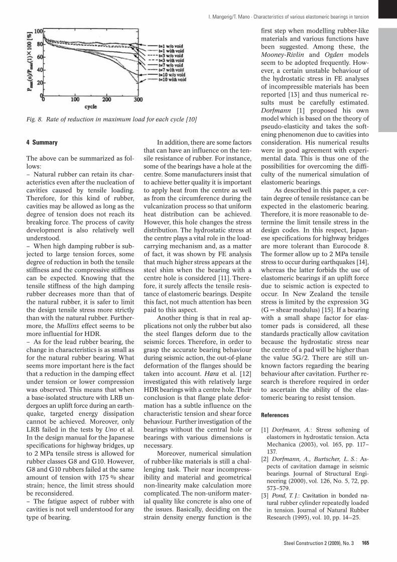
Matsushima et al. [10] studiedhow cavities influence the fatiguecharacteristics of the natural rubberwith up to 300 cyclic loadings. Cavi-ties were caused by unilateral preten-sion beforehand. These tests mostlyshowed that cavities did not have amajor influence on the fatigue char-acteristics of the rubber. However,rubber disks with thicknesses of 7 and10 mm, i.e. disks with smaller shapefactors, exhibited a notable reductionin their shear stiffness because the
damage at the boundary of the rubberdisk and the steel plate occurred dur-ing cyclic loading (γmax = 4) and it expanded along with the number ofcycles. In particular, this was more re-markable in the test piece with cavi-ties as shown in Fig. 8. This amountof shear deformation is quite large;hence, this should not happen fre-quently in real applications. Never-theless, it indicates that cavities couldaffect the fatigue characteristics ofrubber.
I. Mangerig/T. Mano · Characteristics of various elastomeric bearings in tension
Fig. 6. Vertical load-displacement curves of the lead rubber bearing [9](γ: initial offset shear strain, X: breaking points of rubber specimens)
Fig. 7. Comparison of hysteresis loops under compression and tension [9]
165Steel Construction 2 (2009), No. 3
4 Summary
The above can be summarized as fol-lows:– Natural rubber can retain its char-acteristics even after the nucleation ofcavities caused by tensile loading.Therefore, for this kind of rubber,cavities may be allowed as long as thedegree of tension does not reach itsbreaking force. The process of cavitydevelopment is also relatively wellunderstood.– When high damping rubber is sub-jected to large tension forces, somedegree of reduction in both the tensilestiffness and the compressive stiffnesscan be expected. Knowing that thetensile stiffness of the high dampingrubber decreases more than that ofthe natural rubber, it is safer to limitthe design tensile stress more strictlythan with the natural rubber. Further-more, the Mullins effect seems to bemore influential for HDR.– As for the lead rubber bearing, thechange in characteristics is as small asfor the natural rubber bearing. Whatseems more important here is the factthat a reduction in the damping effectunder tension or lower compressionwas observed. This means that whena base-isolated structure with LRB un-dergoes an uplift force during an earth-quake, targeted energy dissipationcannot be achieved. Moreover, onlyLRB failed in the tests by Uno et al.In the design manual for the Japanesespecifications for highway bridges, upto 2 MPa tensile stress is allowed forrubber classes G8 and G10. However,G8 and G10 rubbers failed at the sameamount of tension with 175 % shearstrain; hence, the limit stress shouldbe reconsidered.– The fatigue aspect of rubber withcavities is not well understood for anytype of bearing.
In addition, there are some factorsthat can have an influence on the ten-sile resistance of rubber. For instance,some of the bearings have a hole at thecentre. Some manufacturers insist thatto achieve better quality it is importantto apply heat from the centre as wellas from the circumference during thevulcanization process so that uniformheat distribution can be achieved.However, this hole changes the stressdistribution. The hydrostatic stress atthe centre plays a vital role in the load-carrying mechanism and, as a matterof fact, it was shown by FE analysisthat much higher stress appears at thesteel shim when the bearing with acentre hole is considered [11]. There-fore, it surely affects the tensile resis-tance of elastomeric bearings. Despitethis fact, not much attention has beenpaid to this aspect.
Another thing is that in real ap-plications not only the rubber but alsothe steel flanges deform due to theseismic forces. Therefore, in order tograsp the accurate bearing behaviourduring seismic action, the out-of-planedeformation of the flanges should betaken into account. Hara et al. [12]investigated this with relatively largeHDR bearings with a centre hole. Theirconclusion is that flange plate defor-mation has a subtle influence on thecharacteristic tension and shear forcebehaviour. Further investigation of thebearings without the central hole orbearings with various dimensions isnecessary.
Moreover, numerical simulationof rubber-like materials is still a chal-lenging task. Their near incompress-ibility and material and geometricalnon-linearity make calculation morecomplicated. The non-uniform mater-ial quality like concrete is also one ofthe issues. Basically, deciding on thestrain density energy function is the
first step when modelling rubber-likematerials and various functions havebeen suggested. Among these, theMooney-Rivlin and Ogden modelsseem to be adopted frequently. How-ever, a certain unstable behaviour ofthe hydrostatic stress in FE analysesof incompressible materials has beenreported [13] and thus numerical re-sults must be carefully estimated.Dorf mann [1] proposed his ownmodel which is based on the theory ofpseudo-elasticity and takes the soft-ening phenomenon due to cavities intoconsideration. His numerical resultswere in good agreement with experi-mental data. This is thus one of thepossibilities for overcoming the diffi-culty of the numerical simulation ofelastomeric bearings.
As described in this paper, a cer-tain degree of tensile resistance can beexpected in the elastomeric bearing.Therefore, it is more reasonable to de-termine the limit tensile stress in thedesign codes. In this respect, Japan-ese specifications for highway bridgesare more tolerant than Eurocode 8.The former allow up to 2 MPa tensilestress to occur during earthquakes [14],whereas the latter forbids the use ofelastomeric bearings if an uplift forcedue to seismic action is expected tooccur. In New Zealand the tensilestress is limited by the expression 3G(G = shear modulus) [15]. If a bearingwith a small shape factor for elas-tomer pads is considered, all thesestandards practically allow cavitationbecause the hydrostatic stress nearthe centre of a pad will be higher thanthe value 5G/2. There are still un-known factors regarding the bearingbehaviour after cavitation. Further re-search is therefore required in orderto ascertain the ability of the elas-tomeric bearing to resist tension.
References
[1] Dorfmann, A.: Stress softening ofelastomers in hydrostatic tension. ActaMechanica (2003), vol. 165, pp. 117–137.
[2] Dorfmann, A., Burtscher, L. S.: As-pects of cavitation damage in seismicbearings. Journal of Structural Engi-neering (2000), vol. 126, No. 5, 72, pp.573–579.
[3] Pond, T. J.: Cavitation in bonded na -tural rubber cylinder repeatedly loadedin tension. Journal of Natural RubberResearch (1995), vol. 10, pp. 14—25.
I. Mangerig/T. Mano · Characteristics of various elastomeric bearings in tension
Fig. 8. Rate of reduction in maximum load for each cycle [10]
[4] Notomi, M., Shimosaka, H., Shimoda,H., Suzuki, S., Yoshizwa, T.: Void Nu-cleation of Rubber Material for SeismicIsolation Due to tension Load. Trans-actions of the Japan Society of Me-chanical Engineers (2002), vol. 68, pp.744–749.
[5] Shoji, M., Saito, K.: Seismic perfor-mance of a laminated rubber bearingunder extreme shear deformation sub-jected tension or compression stress.11th Japan Earthquake Symposium2002, pp. 1725—1728.
[6] Kelly, M. J.: Tension Buckling inMultilayer Elastomeric Bearings. Jour-nal of Engineering Mechanics (2003),vol. 129, No. 12, pp. 1363–1368.
[7] Iwabe, N., Kani, N., Takayama, M.,Morita, K., Wada, A.: ExperimentalStudy on the Tension Capacity in theDisplaced Position of Elastomeric iso-lators Part 1 to 5. Annual Meeting Ar-chitectural Institute of Japan, Septem-ber 1999.
[8] Uno, Y., Sumimura, T. Kanai, H.: Re-search regarding the horizontal char-
166 Steel Construction 2 (2009), No. 3
acteristics of various elastomeric bear-ings under tension influence. JSCEJournal of Earthquake Engineering(2003), vol. 27, pp. 1–4.
[9] Otsuka, H., Kuriki, S., Ikenaga, M.: Ex-perimental Study on Ultimate Charac-teristics of Lead Rubber Bearing underTensile Force. Journal of Structural Engi-neering (2002), vol. 48A, pp. 843–850.
[10] Matsushima, C., Notomi, M., Shimo-saka, H., Shimoda, H., Suzuki, S., Yo shi -zawa T.: Low Cycle Fatigue by ShearLoad of Rubber Material for Base Iso-lation. Transactions of Annual Meetingof the Japan Society of Mechanical En-gineers (2004), vol. 1, pp. 123–124.
[11] Home page of M. Takayama:http://4menshin.net/news/index.html
[12] Fukayawa, K., Hara, T., Mochizuki,M., Tachibana, M., Tajima, J.: Experi-mental Study on Tensile Performanceand Shearing Performance under Ten-sile Force of High Damping RubberBearings Part 1 to 3. Annual MeetingArchitectural Institute of Japan (1998),pp. 1137–1142.
[13] Vinay, K. N.: A Numerical Study ofFinite Element Calculations for In-compressible Materials under AppliedBoundary Displacements. Master ofScience Thesis, Department of Me-chanical Engineering, University ofSas kat che wan, Canada, August 2006.
[14] NN.: Bearing support design guidefor highway bridges, Japan, 2004.
[15] Kelly, T. E.: Base Isolation of Struc-tures. Design Guidelines. Holmes Con-sulting Group Ltd, New Zealand, 2001.
Keywords: seismic isolation; elastomericbearing; tensile resistance; cavities
Authors:Prof. Dr.-Ing. Ingbert Mangerig, ToshihisaMano, Universität der Bundeswehr München,Institut für Konstruktiven Ingenieurbau, 85577 Neubiberg, Germany, [email protected]@[email protected]
I. Mangerig/T. Mano · Characteristics of various elastomeric bearings in tension