Embed Size (px)
Citation preview
CHARACTERISTICS OF POLYETHYLENE IMPREGNATED WITH VARIOUS GASESby
T. Kojima, M. Hanai, K. Yagi, K. Okusa, M. Aihara and K. HagaShowa Electric Wire & Cable Co., Ltd.
Tokyo, Japan
EXPERIMENTS AND RESULTS
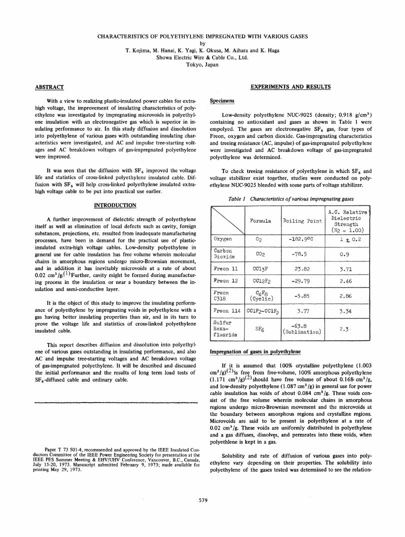
With a view to realizing plastic-insulated power cables for extra-high voltage, the improvement of insulating characteristics of poly-ethylene was investigated by impregnating microvoids in polyethyl-ene insulation with an electronegative gas which is superior in in-sulating performance to air. In this study diffusion and dissolutioninto polyethylene of various gases with outstanding insulating char-acteristics were investigated, and AC and impulse tree-starting volt-ages and AC breakdown voltages of gas-impregnated polyethylenewere improved.
It was seen that the diffusion with SF6 improved the voltagelife and statistics of cross-linked polyethylene insulated cable. Dif-fusion with SF6 will help cross-linked polyethylene insulated extra-high voltage cable to be put into practical use earlier.
INTRODUCTION
A further improvement of dielectric strength of polyethyleneitself as well as elimination of local defects such as cavity, foreignsubstances, projections, etc. resulted from inadequate manufacturingprocesses, have been in demand for the practical use of plastic-insulated extra-high voltage cables. Low-density polyethylene ingeneral use for cable insulation has free volume wherein molecularchains in amorphous regions undergo micro-Brownian movement,and in addition it has inevitably microvoids at a rate of about0.02 cm3 /g:M)Further, cavity might be formed during manufactur-ing process in the insulation or near a boundary between the in-sulation and semi-conductive layer.
It is the object of this study to improve the insulating perform-ance of polyethylene by impregnating voids in polyethylene with agas having better insulating properties than air, and in its turn toprove the voltage life and statistics of cross-linked polyethyleneinsulated cable.
This report describes diffusion and dissolution into polyethyl-ene of various gases outstanding in insulating performance, and alsoAC and impulse tree-starting voltages and AC breakdown voltageof gas-impregnated polyethylene. It will be described and discussedthe initial performance and the results of long term load tests ofSF6-diffused cable and ordinary cable.
Paper T 73 501-4, recommended and approved by the IEEE Insulated Con-ductors Committee of the IEEE Power Engineering Society for presentation at theIEEE PES Summer Meeting & EHV/UHV Conference, Vancouver, B.C., Canada,July 15-20, 1973. Manuscript submitted February 9, 1973; made available forprinting May 29, 1973.
Specimens
Low-density polyethylene NUC-9025 (density; 0.918 g/cm3)containing no antioxidant and gases as shown in Table 1 wereempolyed. The gases are electronegative SF6 gas, four types ofFreon, oxygen and carbon dioxide. Gas-impregnating characteristicsand treeing resistance (AC, impulse) of gas-impregnated polyethylenewere investigated and AC breakdown voltage of gas-impregnatedpolyethylene was determined.
To check treeing resistance of polyethylene in which SF6 andvoltage stabilizer exist together, studies were conducted on poly-ethylene NUC-9025 blended with some parts of voltage stabilizer.
Table I Characteristics of various impregnating gases
A.C. Relative
Formula Boiling Point Dielectric\________ (N2 = 1.00)
Oxygen 0 -182.9°C 1 i 0.2
CarbonDioxide C02 -78.5 09
Freon 11 CC13F 23.82 3.71
Freon 12 CCl2F2 -29.79 2.46
Freon C4F8 -.5280318 (Cyclic) 5.85 2.86
Freon 114 CClF2-CClF2 3.77 3.34
Sulfur -63.8Hiexa- SF6 (Suliatin) 2.3-fluoride(Sbiaon
Impregnation of gases in polyethylene
If it is assumed that 100% crystalline polyethylene (1.003cm3/g)(22)is free from free-volume, 100% amorphous polyethylene(1.171 cm3 /g)(2) should have free volume of about 0. 1681 cm3 /gand low-density polyethylene (1.087 cm3 /g) in general use for powercable insulation has voids of about 0.084 cm3 /g. These voids con-sist of the free volume wherein molecular chains in amorphousregions undergo micro-Brownian movement and the microvoids atthe boundary between amorphous regions and crystalline regions.Microvoids are said to be present in polyethylene at a rate of0.02 cm3/g. These voids are uniformly distributed in polyethyleneand a gas diffuses, dissolves, and penneates into these voids, whenpolyethlene is kept in a gas.
Solubility and rate of diffusion of various gases into poly-ethylene vary depending on their properties. The solubility intopolyethylene of the gases tested was determined to see the relation-
579
ABSTRACT
ship between the quantity of gas dissolved in polyethylene and theelectric properties of gas-impregnated polyethylene. Also, in orderto determine the- conditions for impregnating a gas into cableinsulation, the diffusion coefficient was obtained for some specificgases.
(1) Quantity of gas dissolved in polyethylene and solubility co-
efficient
Polyethylene specimens were placed in autoclaves to whichSF6 and Freon gases were introduced at pressures as shown inTable 2. The autoclaves were kept at 67°C and at 23°C, and were
opened at a certain interval of time to determine gravimetricallythe change of gas dissolution with time. One example of measure-
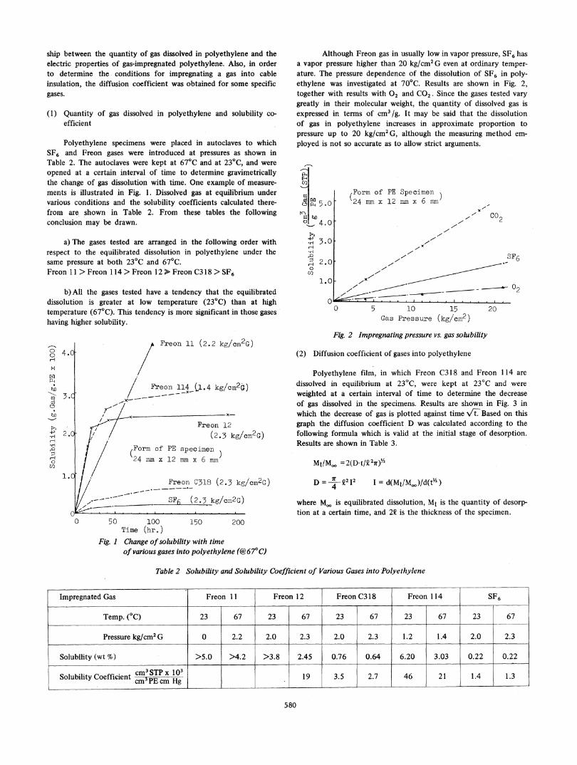
ments is illustrated in Fig. 1. Dissolved gas at equilibrium undervarious conditions and the solubility coefficients calculated there-from are shown in Table 2. From these tables the followingconclusion may be drawn.
a) The gases tested are arranged in the following order withrespect to the equilibrated dissolution in polyethylene under thesame pressure at both 23°C and 67°C.Freon 1 1 > Freon 114 > Freon l2 > Freon C318 > SF6
Although Freon gas in usually low in vapor pressure, SF6 hasa vapor pressure higher than 20 kg/cm2G even at ordinary temper-ature. The pressure dependence of the dissolution of SF6 in poly-ethylene was investigated at 70°C. Results are shown in Fig. 2,together with results with 02 and CO2. Since the gases tested vary
greatly in their molecular weight, the quantity of dissolved gas isexpressed in terms of cm3 /g. It may be said that the dissolutionof gas in polyethylene increases in approximate proportion topressure up to 20 kg/cm2G, although the measuring method em-
ployed is not so accurate as to allow strict arguments.
E-1u)_R
2
PA 5 .
r= wc) 4
_.-p 3.
2.0
CoU2
1.b) All the gases tested have a tendency that the equilibrated
dissolution is greater at low temperature (23°C) than at hightemperature (67°C). This tendency is more significant in those gases
having higher solubility.
.0
.0
.0
(Form of PE Specimen24 mm x 12 mm x 6 Inm
I'l7I
I'l
Co2
1-1", ~ ~~SF6
0 I-,
0 5 10 15Gas Pressure (kg/cm2)
20
Freon 11 (2.2 kg/cm2G)
Freon 114 _Cl4 kg/cm2G)
x-~ ~ ~ ~ ~ x
LK x-Freon 12
(2.3 kg/cm2G)
Form of PE specimen
24 mm x 12 mm x 6 mm
Freon C318 (2.3 kg/cn2G)
- Qv /In,z
0 50 100 150 200Time (hr. )
Fig. I Change ofsolubility with timeof various gases into polyethylene (@67°C)
Fig. 2 Impregnating pressure vs. gas solubility
(2) Diffusion coefficient of gases into polyethylene
Polyethylene film, in which Freon C318 and Freon 114 aredissolved in equilibrium at 23°C, were kept at 23°C and were
weighted at a certain interval of time to determine the decreaseof gas dissolved in the specimens. Results are shown in Fig. 3 inwhich the decrease of gas is plotted against time Vi7 Based on thisgraph the diffusion coefficient D was calculated according to thefollowing formula which is valid at the initial stage of desorption.Results are shown in Table 3.
Mt/M.o = 2(D-t/Q72r)V'
D-= ' 2212 1 = d(Mt/M.,)/d(t"2)where Moo is equilibrated dissolution, Mt is the quantity of desorp-tion at a certain time, and 2Q is the thickness of the specimen.
Table 2 Solubility and Solubility Coefficient of Various Gases into Polyethylene
580
4.C
04 -
@2.C
H
.,
*rl
Co
U22.1 .(
Impregnated Gas Freon I1 Freon 12 Freon C3 18 Freon I 14 SF6
Temp. (°C) 23 67 23 67 23 67 23 67 23 67
Pressure kg/cm2G 0 2.2 2.0 2.3 2.0 2.3 1.2 1.4 2.0 2.3
Solubility (wt %) >5.0 >4.2 >3.8 2.45 0.76 0.64 6.20 3.03 0.22 0.22
Solubility Coefficient cm3STPx 103 19 3.5 2.7 46 21 1.4 1.3cm 3PE cm Hg
bl"6 t2. 5 kg/cmzG;)
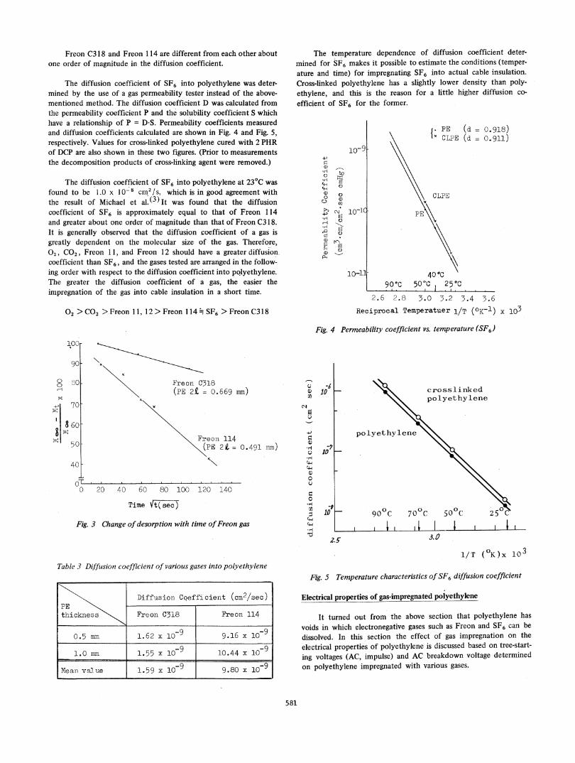
Freon C3 18 and Freon 1 14 are different from each other aboutone order of magnitude in the diffusion coefficient.
The diffusion coefficient of SF6 into polyethylene was deter-mined by the use of a gas permeability tester instead of the above-mentioned method. The diffusion coefficient D was calculated fromthe permeability coefficient P and the solubility coefficient S whichhave a relationship of P = D-S. Permeability coefficients measuredand diffusion coefficients calculated are shown in Fig. 4 and Fig. 5,respectively. Values for cross-linked polyethylene cured with 2 PHRof DCP are also shown in these two figures. (Prior to measurementsthe decomposition products of cross-linking agent were removed.)
The diffusion coefficient of SF6 into polyethylene at 23°C wasfound to be 1.0 x 10⁻⁸ cm.2/s, which is in good agreement withthe result of Michael et al. (3) It was found that the diffusioncoefficient of SF6 is approximately equal to that of Freon 114and greater about one order of magnitude than that of Freon C318.It is generally observed that the diffusion coefficient of a gas isgreatly dependent on the molecular size of the gas. Therefore,02, C02, Freon 11, and Freon 12 should have a greater diffusion.coefficient than SF6, and the gases tested are arranged in the follow-ing order with respect to the diffusion coefficient into pQlyethylene.The greater the diffusion coefficient of a gas, the easier theimpregnation of the gas into cable insulation in a short time.
02 > C02 >.Freon 1 1, 12 > Freon 1 14 SF6 > Freon C318
The temperature dependence of diffusion coefficient deter-mined for SF6 makes it possible to estimate the conditions (temper-ature and time) for impregnating SF6 into actual cable insulation.Cross-linked polyethylene has a slightly lower density than poly-ethylene, and this is the reason for a little higher diffusion co-
efflcient of SF6 for the former.
+D
' ) i--.HC.)
H\aCH61) o
a)
10-1-q
10-11
I. PE (d = 0.918)CxCLPE (d = 0.911)
CLPE
40°C90°C 50-% 25°C
i . .- .
2.6 2.8 3.0 3.2 3.4 3.6Reciprocal Temperatuer l/T (OK-') x 103
Fig. 4 Permeability coefficient vs. temperature (SF6)
Freon C318(PE 2t = 0.669 m)
Freon 114(PE 2i = 0.491 mm)
I--Q
.H
.H
61)
CD
0
r.
.re
-0
20 40 60 80 100 120 140
Time Ft( sec )
Fig. 3 Change ofdesorption with time ofFreon gas
-610
10
-110
crosslinkedpolyethylene
polyethylene
90°C90 C
.01 I3.0
Diffusion Coeffi cient (cm2/sec)PEthickness Freon C318 Freon 114
0.5 mm 1.62 x 10⁻⁹ 9.16 x 10⁻⁹
1.0 mn 1.55 x 10⁻⁹ 10.44 x 10⁻⁹
Mean) value 1.59 x 10 9.80 x 10
1/T (°K)x 103
Fig. 5 Temperature characteristics of SF6 diffusion coefficient
Electrical properties of gas-impregnated polyethylene
It turned out from the above section that polyethylene hasvoids in which electronegative gases such as Freon and SF6 can be
dissolved. In this section the effect of gas impregnation on theelectrical properties of polyethylene is discussed based on tree-start-
ing voltages (AC, impulse) and AC breakdown voltage determinedon polyethylene impregnated with various gases.
581
100
90 Kl
I-g 80
N,+P 70
8608Itg~ ;n~
40
0Lo
Table 3 Diffusion coefficient of various gases into polyethylene
Wr.L
(1) AC tree-starting voltage
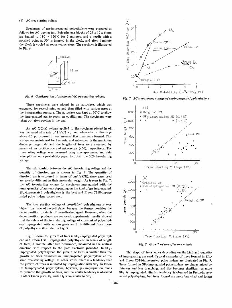
Specimens of gas-impregnated polyethylene were prepared asfollows for AC treeing test. Polyethylene blocks of 24 x 12 x 6 mmare heated to 110 - 120°C for 5 minutes, and a needle with apolished point at 300 is inserted in the block, and after 1 minutethe block is cooled at room temperature. The specimen is illustratedin Fig. 6.
a1)S
C.3'S
H0
*,D
.H
'C'Co
0L4-SH)
K>)
24 lmm
6 amn
1 2 mmun
Fig. 6 Configuration ofspecimen (AC tree-starting voltage)
30 h SF6
25 F
20 [
Ax"300 114-A Freon 12
Freon 11-
~~ ~ ~ C0215 L
10-r Originlal PE
0 i0 1 2 3 4 5
Gas Solubility (cmn3-STP/g PE)
Fig. 7 AC tree-starting voltage ofgas-impregnated polyethylene
These specimens were placed in an autoclave, which wasevacuated for several minutes and then filled with various gases atthe impregnating pressure. The autoclave was kept at 70°C to allowthe impregnated gas to reach an equilibrium. The specimens weretaken out after cooling in the gas.
An AC (5OHz) voltage applied to the specimen placed in oil.was increased at a rate of 1 kV/3 s., and wh;en electric dischargeabove 0.5 pc occurred it was assumed that trees were formed. Thisvoltage was maintained for 1 minute, and subsequently the maximumdischarge magnitude and the lengths of trees were measured bymeans of an oscilloscope and microscope (x60), respectively. Thetree-starting voltage was measured using nine specimens, and datawere plotted on a probability paper to obtain the 50% tree-startingvoltage.
The relationship between the AC tree-starting Voltage and thequantity of dissolved gas is shown in Fig. 7. The quantity ofdissolved gas is expressed in terms of cm3/g (PE), since gases usedare greatly different in their molecular weight. As is seen in Fig. 7,the AC tree-starting voltage for specimens impregnated with thesame quantity of gas vary depending on the kind of gas impregnated.SF6-impregnated polyethylene is the best and Freon C318-impreg-nated polyethylene comes next.
The tree starting voltage of cross-linked polyethylene is veryhigher than one of polyethylene, because the former contains thedecomposition products of cross-linking agent. However, when thedecomposition products are removed, experimental results showedthat the values of the tree starting voltage of cross-linked polyethyl-ene impregnated with various gases are little different from thoseof polyethylene illustrated in Fig. 7.
Fig. 8 shows the growth of trees in SF6-impregnated polyethyl-ene and Freon C318 impregnated polyethylene in terms of lengthof trees, 1 minute after tree occurrence, measured in the verticaldirection with respect to the plate electrode grounded. In SF6-impregnated polyethylene the growth of trees is smaller than thegrowth of trees estimated in unimpregnated polyethylene at thesame tree-starting voltage. In other words, there is a tendency thatthe growth of trees is inhibited -by impregnation with SF6. In FreonC318-impregnated polyethylene, however, gas impregnation tendsto promote the growth of trees, and the similar tendency is observedin other Freon gases. 02 and CO2 were similar to SF6.
582
1200 [
91,1000
-1-, 6,00ELOCD
C) 600a)
4q400
200
i)
(a)x Original PEo SF6 impregnated* I, I?
x7/xx,
,KI x
O
0
1200[
ba,
Q1)
$4
F'-
PE (O.6o57")
" (1.3 A)/I
I/A'
I''Original PE
0 00 0
o 0
10 20Tree Starting Voltage (Kv)
(b)x Original PEo C351-impregnated
it" .100[
800[
600[
400
200
0
30
PE (O.05c) ..*(1.17>) /A
0 A/7
7
10 20Tree Starting Voltage (Kv)
* AI/ Original PE
F4
30
Fig. 8 Growth of tree after one minute
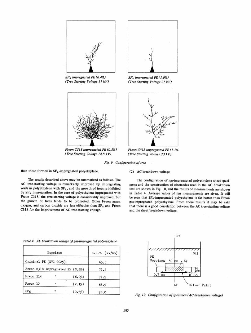
The shape of trees varies depending on the kind and quantityof impregnating gas used. Typical examples of trees formed in SF6-and Freon C318-impregnated polyethylene are illustrated in Fig. 9.Trees formed in SF6-impregnated polyethylene are characterized bythinness and less branching, and this becomes significant as more
SF6 is impregnated. Similar tendency is observed in Freon-impreg-nated polyethylene, but trees formed are more branched and longer
0/
0 00 ,0 Aa /
,xx/xXx
, x070
, r
SF6 impregnated PE (0. 4%o) SF6 impregnated PE (1.0%)(Tree Starting Voltage 17 kV) (Tree Starting Voltage 21 kV)
Freon C318 impregnated PE (0.5%) Freon C318 impregnated PE (1.1%o(Tree Stqrting Voltage 14.8 k V) (Tree Starting Voltage 23 kV)
Fig. 9 Configuration of tree
than those formed in SF6-impregnated polyethylene.
The results described above may be summarized as follows. TheAC tree-starting voltage is remarkably improved by impregnatingvoids in polyethylene with SF6, and the growth of trees is inhibitedby SF6 impregnation. In the case of polyethylene impregnated withFreon C318, the tree-starting voltage is considerably improved, butthe growth of trees tends to be promoted. Other Freon gases,oxygen, and carbon dioxide are less effective than SF6 and FreonC318 for the improvement of AC tree-starting voltage.
Table 4 AC breakdown voltage ofgas-impregnated polyethylene
Spacinen B. D. V. (kV/mrn)
Original PE (NVC 9025) 65.0
Freon C318 impregnated PE (0.5%) 71.8
Freon 114 6.(60%) 71.5
Freon 12 (2 1%) 68.5
SF6 (o.5F%) 98.0
(2) AC breakdown voltage
The configuration of gas-impregnated polyethylene sheet speci-mens and the construction of electrodes used in the AC breakdowntest are shown in Fig. 10, and the results of measurements are shownin Table 4. Average values of ten measurements are given. It willbe seen that SF6-impregnated polyethylene is far better than Freongas-impregnated polyethylene.' From these results it may be saidthat there is a good correlation between the AC tree-starting voltageand the sheet breakdown voltage.
HV
777777777z /'77'/ /Oil
PESpeciinen 30 mm Hg
0 7mn R 2.5
LV Silver Paint
Fig. 10 Configuration ofspecimen (AC breakdown voltage)
583
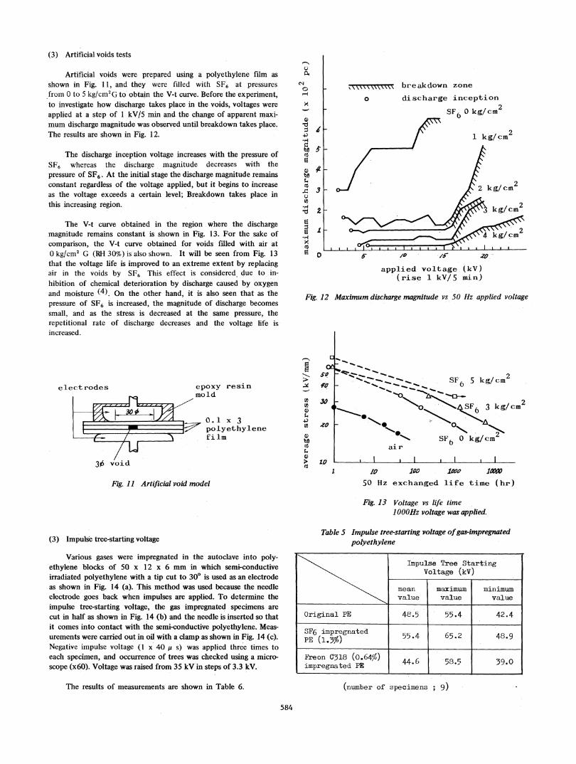
(3) Artificial voids tests
Artificial voids were prepared using a polyethylene film asshown in Fig. 11, and they were filled with SF6 at pressuresfrom 0 to 5 kg/cm2G to obtain the V-t curve. Before the experiment,to investigate how discharge takes place in the voids, voltages wereapplied at a step of I kV/S min and the change of apparent maxi-mum discharge magnitude was observed until breakdown takes place.The results are shown in Fig. 12.
The discharge inception voltage increases with the pressure ofSF6 whereas the discharge magnitude decreases with thepressure of SF6. At the initial stage the discharge magnitude remainsconstant regardless of the voltage applied, but it begins to increaseas the voltage exceeds a certain level; Breakdown takes place inthis increasing region.
The V-t curve obtained in the region where the dischargemagnitude remains constant is shown in Fig. 13. For the sake ofcomparison, the V-t curve obtained for voids filled with air at0 kg/cm2 G (RH 30%) is also shown. It will be seen from Fig. 13that the voltage life is improved to an extreme extent by replacingair in the voids by SF6 This effect is considered due to in-hibition of chemical deterioration by discharge caused by oxygenand moisture (4). On the other hand, it is also seen that as thepressure of SF6 is increased, the magnitude of discharge becomessmall, and as the stress is decreased at the same pressure, therepetitional rate of discharge decreases and the voltage life isincreased.
el(ectrodes epoxy resin___ ___ ___ ___ ___ ___ mold
O. l0.1 x 3I polyethyl
/r A Ifilm
3,6 void
0
04
4.)
S
x
,4)
.H
.0
,t
x
CZ
CD
U /I /5 .209.-applied voltage (kV)
(rise 1 kV/5 mn)
Fig. 12 Maximum discharge magnitude vs 50 Hz applied voltage
0!ot
30
_ .. SF6 5 kg/cm2ft..~% 6~
t~ ~ ~ N>o A SF6 3 kg!cm2
SFt, 0 kg/cm2air 6
l I
1 10
50 Hz
100 10boexchanged life time (hr)
-
I
U)In
4.)4U)0S
ene
Fig. 11 Artificial void model
Fig. 13 Voltage vs life timeI OOHz voltage was applied.
(3) Impulse tree-starting voltage
Various gases were impregnated in the autoclave into poly-ethylene blocks of 50 x 12 x 6 mm in which semi-conductiveirradiated polyethylene with a tip cut to 30° is used as an electrodeas shown in Fig. 14 (a). This method was used because the needleelectrode goes back when impulses are applied. To determine theimpulse tree-starting voltage, the gas impregnated specimens arecut in half as shown in Fig. 14 (b) and the needle is inserted so thatit comes into contact with the semi-conductive polyethylene. Meas-urements were carried out in oil with a clamp as shown in Fig. 14 (c).Negative impulse voltage (1 x 40 p s) was applied three times toeach specimen, and occurrence of trees was checked using a micro-scope (x60). Voltage was raised from 35 kV in steps of 3.3 kV.
The results of measurements are shown in Table 6.
Table S Impulse tree-starting voltage ofgas-impregnatedpolyethylene
Impulse Tree StartingVoltage (kV)
mean maximum minimumvalue value value
Original PE 48.5 55.4 42.4
SF6 impregnated(1.3%) 65.2 .48.9
Freon318(.64%) 44.6 58.5 39.0impregnated PE
(number of specimens ; 9)
584
I l
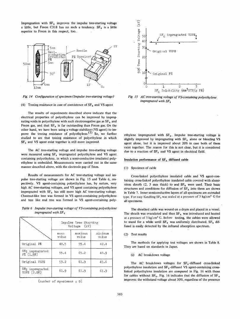
Impregnation with SF6 improves the impulse tree-starting voltagea little, but Freon C318 has no such a tendency. SF6 is a littlesuperior to Freon in this respect, too.
T-I I C , HV
12am
Fig. 14 Configuration ofspecimen (Impulse tree-starting voltage)
(4) Treeing resistance in case of coexistence of SF6 and VS agent
Q3
4< 5040
20a)
H+ 50
a)
Ed
0
SF impregnated VSPE
. Orga V
Origiiial VSPE
7'N Original PE
l1l 2 5
SF6 Solubility (cm3STP/g PE)
Fig. 15 AC tree-starting voltage of VS-containing polyethyleneimpregnated with SF6
The results of experiments described above indicate that theelectrical properties of polyethylene can be improved by impreg-nating voids in polyethylene with such electronegative gas as SF6 andFreon gas, and that SF6 is far outstanding than Freon gas. On theother hand, we have been using a voltage stabilizer (VS agent) to im-prove the treeing resistance of polyethylene.(5) So, we furtherstudied to see that treeing resistance of polyethylene in whichSF6 and VS agent exist together is still more improved.
The AC tree-starting voltage and impulse tree-starting voltagewere measured using SF6 impregnated polyethylene and VS agentcontaining polyethylene, in which a semi-conductive irradiated poly-ethylene is embedded. Measurements were carried -out in the samemanner described above, with the electrode gap of 5mm.
Results of measurements for AC tree-starting voltage and im-pulse tree-starting voltage are shown in Fig. 15 and Table 6, res-pectively. VS agent-containing polyethylene has, by nature, veryhigh AC tree-starting voltages, and VS agent containing polyethyleneimpregnated with SF6 has still more high AC tree-starting voltage.Chestnut-like tree was formed in VS agent-containing polyethyleneand tree like real tree was formed in VS agent-containing poly-
Table 6 Impulse tree-starting voltage of VS-containing polyethyleneimpregnated with SF6
Impulse Tree StartingVoltage (kV)
mean maximum minimumvalue value value
Original PE 48.5 55.4 42.4
SF6 impregnated 55.4 65.2 48.9PE (1.5%)
Original VSPE 55.2 61.9 45.6
SF6 impregnated 61.9 61.9 61.9
VSFE (2.0%)(number of specimens ;9)
ethylene impregnated with SF6. Impulse tree-starting voltage isslightly improved by impregnating with SF6 alone or blending VSagent alone, but it is improved about 20% in case both of themexist together. The reason for this is not clear, but it is considereddue to a reaction of SF6 and VS agent in electrical field.
Insulation performance of SF6 diffused cable
(1) Specimen of cable
Cross-linked polyethylene insulated cable and VS agent-con-taining cross-linked polyethylene insulated cable covered with alumi-nium sheath (2, 3 mm thick) to seal SF6 were used. Their basicstructures and conditions for diffusion of SF6 into them are shownin Table 7. Inner semiconductive layers of all specimens are extrudedtype. For easy handling SF6 was sealed at a pressure of 3 kg/cm2 G forall specimens.
The sheathed cable was wound on a drum and placed in a vessel.The sheath was evaculated and then SF6 was introduced and heatedat a pressure of 5 kg/cm2 G. Before testing, the cables were allowedto stand for a while until SF6 was uniformly distributed. SF6 dif-fused is easily detected by the infrared absorption spectrum.
(2) Test results
The methods for applying test voltages are shown in Table 8.They are based on standards in Japan.
(i) AC breakdown voltage
The AC breakdown voltages for SF6-diffused cross-linkedpolyethylene insulation and SF6-diffused VS agent-containifig cross-linked polyethylene insulation are compared in Fig. 16 with thosefor cables without SF6. Fig. 16 indicates that the diffusion of SF6improves the withstand voltage about 30%, regardless of the presence
585
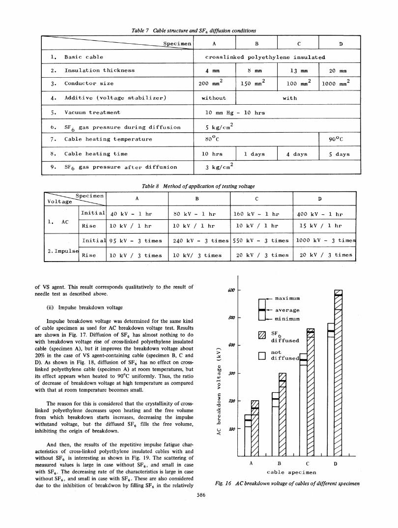
Table 7 Cable structure and SF6 diffusion conditions
m[m_nSpecimen A B C D
1. Basic cable crosslinked polyethylene insulated
2. Insulation thickness 4 mm 8 mm 13 mm 20 mm
2 u2 10 m2 23. Conductor size 200 mm 150 m 0 n 1000 mm2
4. Additive (voltage stabilizer) without with
5. Vacuum treatment 10 mm Hg - 10 hrs
6. SF6 gas pressure during diffusion 5 kg/cm27. Cable heating temperature 800C 90°C
8. Cable heating time 10 hrs 1 days 4 days 5 days
9. SF6 gas pressure after diffusion 3 kg/cm2
Table 8 Method ofapplication of testing voltage
pcimen A B C D
Initial' 4 kV- 1 hr 80 kV- 1 hr 160 kV- 1 hr 400kV- 1 hrI AC
Rise 10 kV/ 1 hr 10 kV/ 1 hr 10 kV / hr 15 kV/ 1 hr
Initial 95 kV - 3 times 240 kV - 3 times 550 kV - 3 times 1000 kV - 3 times
2. ImpulseL I ~Rise |1C kV /3 times |10 kV/ 3 times |20 kV /3 times |20 kV /3 times|
of VS agent. This result corresponds qualitatively to the result ofneedle test as described above.
(ii) Impulse breakdown voltage
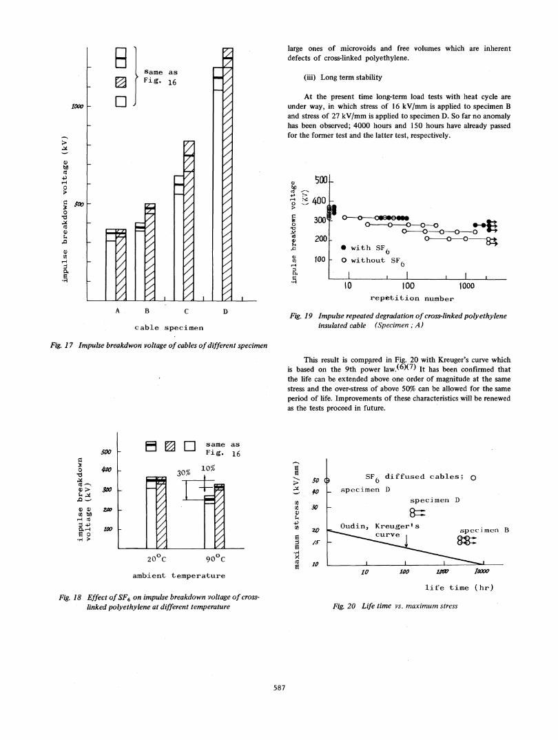
Impulse breakdown voltage was determined for the same kindof cable specimen as used for AC breakdown voltage test. Resultsare shown in Fig. 17. Diffusion of SF6 has almost nothing to dowith breakdown voltage rise of cross-linked polyethylene insulatedcable (specimen A), but it improves the breakdown voltage about20% in the case of VS agent-containing cable (specimen B, C andD). As shown in Fig. 18, diffusion of SF6 has no effect on cross-linked polyethylene cable (specimen A) at room temperatures, butits effect appears when heated to 90°C uniformly. Thus, the ratioof decrease of breakdown voltage at high temperature as comparedwith that at room temperature becomes small.
The reason for this is considered that the crystallinity of cross-linked polyethylene decreases upon heating and the free volumefrom which breakdown starts increases, decreasing the impulsewithstand voltage, but the diffused SF6 fills the free volume,inhibiting the origin of breakdown.
And then, the results of the repetitive impulse fatigue char-acteristics of cross-linked polyethylene insulated cables with andwithout SF6 is interesting as shown in Fig. 19. The scattering ofmeasured values is large in case without SF6, and small in casewith SF6. The decreasing rate of the characteristics is large in casewithout SF6, and small in case with SF6. These are also considereddue to the inhibition of breakdwon by filling SF6 in the relatively
--
C)
b0C
0
C)0
IdcX¢~
maximum
_- average
i minimum
SF6diffused
D notIJ di ffusedF
30o k
zx F
100 h
7
//////
F
r
//////////
////////44
4HA B C
cable specimen
Fig. 16 AC breakdown voltage of cables ofdifferent specimen
586
1-7,1-7
D
av .
-
=
same as-
2 Fig. 16
_ [0
A B
/
/
7-44./////////////////4/4444444444V
C D
cable specimen
large ones of microvoids and free volumes which are inherentdefects of cross-linked polyethylene.
(iii) Long term stability
At the present time long-term load tests with heat cycle areunder way, in which stress of 16 kV/mm is applied to specimen Band stress of 27 kV/mm is applied to specimen D. So far no anomalyhas been observed; 4000 hours and 150 hours have already passedfor the former test and the latter test, respectively.
w 500
X, 400
W 3000
4) 200s4IC
U)X 100
rE,Hr
I
O -O---O 0-0
O7 iO
w with Sr60 without SF,
I0l100 1000
repetition number
Fig. 19 Impulse repeated degradation of cross-linked polyethyleneinsulated cable (Specimen; A)
Fig. 17 Impulse breakdwon voltage of cables ofdifferent specimen
This result is comppred in Fig. 20 with Kreuger's curve whichis based on the 9th power law.(6)(7) It has been confirmed thatthe life can be extended above one order of magnitude at the same
stress and the over-stress of above 50% can be allowed for the same
period of life. Improvements of these characteristics will be renewedas the tests proceed in future.
0
*H
500
300
300
£0W
a
-I]
4-)
co
20°C 900Cambient temperature
Fig. 18 Effect ofSF6 on impulse breakdown voltage of cross-
linked polyethylene at different temperature
s0#0
30
zo
/10
10
SF6
specimen
Oudin, Kr
diffused cables; 0D
specimen D
-euger'sspecimen B
Lrve Ir
10 100 1ow lAW
life time (hr)
Fig. 20 Life time vs. maximum stress
587
1X0l
AV _
-
-)
4.)0
0-d
U)CU
0.i-
CONCLUSION
The solubility coefficient and diffusion coefficient of variousgases into polyethylene vary to a great extent depending on the typeof gas used. Usually, Freon gas except Freon C318 is easier toimpregnate than SF6. Although Freon C318 has a little greatersolubility coefficient than SF6, Freon C318 requires about 10 timesmore time than SF6 in order that an equilibrium is reached at acertain pressure, because Freon C3 18 has a small diffusion co-efficient.
AC tree-starting voltage and AC breakdown voltage of poly-ethylene are improved by impregnating such electronegative gas asFreon gas, SF6, etc. SF6 is particularly effective at the samequantity of impregnation, and Freon C318 comes next. SF6 im-pregnation inhibits the growth of trees in polyethylene, but Freongas impregnation promotes the growth of trees.
SF6 impregnation improves impulse tree-starting voltage onlya little, and Freon C318 makes almost no improvement. However,impulse tree-starting voltage is remarkably improved when SF6 andvoltage stabilizer (VS agent) exist together.
Now, it has been elucidated that SF6 is best as an impregnatinggas to improve the electrical properties of polyethylene.
By diffusing SF6 at 3 kg/cm2 GCinto cross-inked polyethylenecable insulation with VS agent, the AC breakdown voltage andimpulse breakdwon voltage can be improved 30% and 20%, res-pectively.
The impulse breakdwon voltage of cross-linked polyethylenein case diffused with SF6, is improved at high temperatures. Andthen, its decreasing rate of repetitive impulse fatigue characteristicsis remarkably improved.
It is inferred from the long-term load tests under way forSF6-diffused cross-linked polyethylene insulated high voltage powercable, that the life will be extended above one order of magnitudeat the same stress and the overstress of above 50% is allowed atthe same life, compared with Kreuger's V-t curve.
The SF6 diffusion system is not necessarily a satisfactorymeans, but it will promote cross-linked polyethylene insulated cablefor high voltage (275 kV class) to practical use. The use of sheathfor this class of cable is advantageous because the sheath can beused also as the return sheath in which short-circuit current mayrun to the extent of 50 kA.
REFERENCES
(1) S. Matsuoka, "Hypothesis of Voids in Semicrystalline Polymers,"J. Appl. Phys., Vol. 32, pp. 2334-2336, Nov. 1961.
(2) A.S. Michaels and H.J. Bixler, "Solubility of Gases in Poly-ethylene," J. Polymer Sci., Vol. 50, pp. 393-412, 1961.
(3) A.S. Michaels and H.J. Bixler, "Flow of Gases Through Poly-ethylene," J. Polymer Sci., Vol. 50, pp. 413-439, 1961.
(4) M. Sone, S. Kojima, A. Machida, Y. Toriyama, T. Henmi andT. Kihara, "Investigation of Generation Mechanism of AC Treeand Corona Degradation in Organic Insulator," Proc. of 5th onSymposium on Electrical Insulating Materials (IEE of Japan)1972.
(5) K. Kanazawa, H. Furuyama and I. Harashima, "Development ofVoltage Stabilized Cross-Linked Polyethylene Power Cable andTheir Accessories in Japan," IEEE Summer Power Meeting andEHV Conference, Paper No. 70 CP 555-PWR, 1970.
(6) F.H. Kreuger, "Endurance Tests with Polyethylene InsulatedCable," CIGRE 1968-Paper No. 21-02.
(7) J.M. Oudin and Ch. A. Flamand, "The Use of ThermoplasticInsulating Material in the Manufacture of DC and AC-Cables,"CIGRE 1962, paper No. 209.
ACKNOWLEDGEMENTS
We would like to acknowledge Mr. M. Morita for his helpfuldiscussion. We also express our gratitude to M. Okada, I. Kajiki andY. Ebinuma for their supply of useful advice and cooperation.
Discussion
R. B. Blodgett, (Anaconda Wire And Cable Company, New York, N.Y.10016): 1 would like to confirm that impregnation of polyethylenewith electronegative gases does improve electrical properties of poly-ethylene but, of course, at the price of increasing the complexity of thesystem. About ten years ago, the company with which I am associatedsubmitted to the Southern California Edison Company proving groundfor 69 kV cables, a cable insulated with polyethylene tapes and filledwith a mixture of electronegative gases. The wall thickness was sub-stantially less than that of a conventional low-pressure gas-filled paper-cable for the same voltage, but electrical properties were excellent.However, the cable failed in the proving ground apparently as the resultof a leak in the lead sheath.
It is also interesting to compare the permeability coefficient ofwater and its temperature dependence, as reported by Wilkins (1), tothe values for electronegative gases given in the subject paper. When thedata in Wilkins' Figure 5 are converted to the same units as those in theauthors' figure 4, the values tabulated below are obtained.
PERMEABILITY COEFFICIENT INCm3 - Cm/Cm22, SeC Cm Hg XlIfr8
50C 70C 90CEP 8.1 6.7 14.0XLP 4.4 3.8 7.8PE 2.2 2.6 5.2
Assumptions used in conversion were that:(1) Water vapor is ideal gas.(2) Effective cable diameter is one cm.(3) Vapor pressure equals zero in conductor interstices.These data show water vapor to have a ten-fold higher permeabil-
ity than electronegative gases. This is interesting in view of the fact thatwater has the lowest permeability of all the liquids studied by Bent &Pinsky.(2)
REFERENCES
(1) T 73 498-3, A Study of Treeing in Medium Voltage Power Cables"by W. E. Wilkins presented at the 1973 Summer Power Meeting.
(2) "Theoretical Investigation of the Mechanism of Transfer of Mate-rials Through Polyethylene" by H. A. Bent and J. Pinsky, WrightAir Development Center Technical Report 53-133 August 1955.
Manuscript received August 3, 1973.
T. Kojima, M. Hanai, K. Yagi, K. Okusa, M. Aihara, and K. Haga: Cer-tainly electrical properties of polyethylene are improved by -impreg-nating such electronegative gas as Freon gas, SF6 etc. SF6 is particularlyeffective at the same quantity of impregnation.
To turn SF6 diffused cross-linked polyethylene insulated highvoltage power cable to practical use, a manufacturing process for diffu-sion of SF6 and metal sheath to maintain SF6 are necessary. But diffu-
Manuscript received October 15, 1973.
588
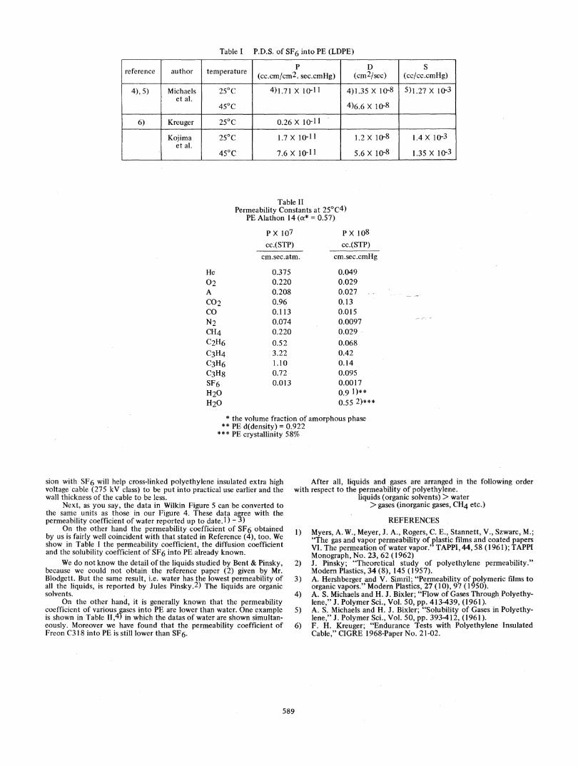
Table I P.D.S. of SF6 into PE (LDPE)
reference author temperature 2D(cc.cm/cm2. sec.cmHg) (cm2/sec) (cc/cc.cmHg)
4),5) Michaels 250C 4)1.71 X i0o1l1 4)1.35 X 1it8 5)1.27 X 1i03et al.
450C 4)6.6 X 10⁻⁸
6) Kreuger 250C 0.26 X 10- 11
Kojima 250C 1.7 X 10⁻¹¹ 1.2 X 10⁻⁸ 1.4 X 10⁻³et al.
450C 7.6 X 10⁻¹¹ 5.6 X 10⁻⁸ 1.35 X 1io3
Table IIPermeability Constants at 25°C4)
PE Alathon 14 (a* = 0.57)
P>X 107cc.(STP)
cm.sec.atm.
PX 108cc.(STP)
cm.sec.cmHg
He 0.375 0.04902 0.220 0.029A 0.208 0.027C02 0.96 0.13Co 0.113 0.015N2 0.074 0.0097CH4 0.220 0.029C2H6 0.52 0.068C3H4 3.22 0.42C3H6 1.10 0.14C3H8 0.72 0.095SF6 0.013 0.0017H20 0.9 1)**H20 0.55 2)***
* the volume fraction of amorphous phase** PE d(density) = 0.922
*** PE crystallinity 58%
sion with SF6 will help cross-linked polyethylene insulated extra highvoltage cable (275 kV class) to be put into practical use earlier and thewall thickness of the cable to be less.
Next, as you say, the data in Wilkin Figure 5 can be converted tothe same units as those in our Figure 4. These data agree with thepermeability coefficient of water reported up to date. 1) 3)
On the other hand the permeability coefficient of SF6 obtainedby us is fairly well coincident with that stated in Reference (4), too. Weshow in Table I the permeability coefficient, the diffusion coefficientand the solubility coefficient of SF6 into PE already known.
We do not know the detail of the liquids studied by Bent & Pinsky,because we could not obtain the reference paper (2) given by Mr.Blodgett. But the same result, i.e. water has the lowest permeability ofall the liquids, is reported by Jules Pinsky.2) The liquids are organicsolvents.
On the other hand, it is generally known that the permeabilitycoefficient of various gases into PE are lower than water. One exampleis shown in Table 11,4) in which the datas of water are shown simultan-eously. Moreover we have found that the permeability coefficient ofFreon C318 into PE is still lower than SF6.
After all, liquids and gases are arranged in the following orderwith respect to the permeability of polyethylene.
liquids (organic solvents) > water> gases (inorganic gases, CH4 etc.)
REFERENCES1) Myers, A. W., Meyer, J. A., Rogers, C. E., Stannett, V., Szwarc, M.;
"The gas and vapor permeability of plastic films and coated papersVI. The permeation of water vapor." TAPPI, 44,58 (1961); TAPPIMonograph, No. 23, 62 (1962)
2) J. Pinsky; "Theoretical study of polyethylene permeability."Modem Plastics, 34 (8), 145 (1957).
3) A. Hershberger and V. Simril; "Permeability of polymeric films toorganic vapors." Modern Plastics, 27 (10), 97 (1950).
4) A. S. Michaels and H. J. Bixler; "Flow of Gases Through Polyethy-lene," J. Polymer Sci., Vol. 50, pp. 413439, (1961).
5) A. S. Michaels and H. J. Bixler; "Solubility of Gases in Polyethy-lene," J. Polymer Sci., Vol. 50, pp. 393412, (1961).
6) F. H. Kreuger; "Endurance Tests with Polyethylene InsulatedCable," CIGRE 1968-Paper No. 21-02.
589