Embed Size (px)
Citation preview
Abstract—This paper investigates on the
characteristics of current when lightning strikes on the
conductor of transmission lines. The impedance of
multistory model based on the 115 kV transmission
tower is employed to simulate in EMTP/ATPDraw
program. The location of lightning strikes on the
conductor on transmission lines and the ground
resistance is varied. The characteristics of the peak
amplitudes and the first peak time of current waveform
are observed. The obtained results show that when
lightning striking occurs near the substation, the peak
amplitudes of current tend to increase with decreasing
distance between the substation and the lightning
location. In addition, the first peak time tends to
decrease with decreasing distance between the substation
and the lightning location, and its change will be very
useful in the development of lightning location scheme.
Index Terms— Lightning, Multistory model, EMTP,
Lightning location, Transmission line
I. INTRODUCTION
lectricity is becoming increasingly more important for
everyday life, and likewise, its demand by the
population and the economic growth. Most modern facilities
require power generated by electricity, facilities such as
school, hospital, entertainment sector, government
properties, and etc. Therefore, it is imperative that electricity
must be stably secured with the effective control systems and
transfer systems. These systems are installed in the form of
transmission system, and injected the power without
interruption. However, the complexity of transmission
network that injects the power into wide area may likely
cause the electrical failure or power outages due to,
specifically, the natural lightning striking on the transmission
network. This often leads to power outages in the power
system. In the literature, there are many research studies [1-
25] about lightning protection in power system.
A vertically grounded system that has a pure resistance of
5 Ohms (parameters of capacitance and inductance are
negligible) was discussed in [1]. The most frequent issues
with the power system were its shielding failures, which can
affect the stability of the system and the economy to a large
degree. Shielding of the lightning current with different
models was analyzed in [2]. Nowadays, there have been
many models which are used to approximate Shielding
Failure Flashover Rate (SFFOR) such as Suzuki’s model [3],
Borghetti’s model [4], Anderson’s model [5] (which is not
suitable to be considered), Eriksson’s model [6],
Armstrong’s model [7], Wagner’s model [8], and Mousa’s
model [9]. By considering in terms of performance and cost,
the electro-geometric model is the most active, while the
Eriksson’s model [6] is based on unrealistic assumptions.
Shielding Failure Rate (SFR) and SFFOR are both affected
by height. Most researches that only calculate the amplitude
of the current and samples used for analysis are insufficient.
The lightning current waveforms are used to demonstrate the
trend of current. It uses parameters such as the amplitude of
the current, front duration, and the rate of rise. These
parameters affect the overload as observed in power stations
[10]. The effect of systems with different polarity of
lightning and stimulation in the Alternative Transients
Program/Electromagnetic Transients Program (ATP/EMTP)
program was studied in [11]. The result examined how the
system was affected when lightning strikes on different
points of the system, such as the power pole, and various
segments of the overhead ground wires by using many
computer programs for simulation [12-16]. Although the
lightning protection was studied, but the behaviour of
current during the lightning strike is necessary to understand
variation of current waveforms before doing a decision
algorithm.
In this paper, the characteristic of the current waveforms
is analysis about the variation of current waveforms. The
lightning conditions will be simulated using ATP/EMTP due
to it is probably the simulator for transient phenomena of
electromagnetic [17-22]. The 115 kV Thailand’s
transmission system is considered for simulation. The
behaviour based on the peak amplitude current and the first
peak time, during the lightning striking on the conductor of
transmission line, are investigated. The location of lightning
and the resistance of ground transmission tower are varied
and compared.
P. Lertwanitrot, P. Kettranan, P. Itthisathienkul and A. Ngaopitakkul
Characteristics and Behaviour of Transient
Current during Lightning Strikes on
Transmission Tower
E
Manuscript received January 9, 2015
This work was supported in part from King Mongkut’s Institute of
Technology Ladkrabang Research fund, Thailand
Prailkanok Lertwanitrot, Patcharaporn Kettranan and Pimsiri
Itthisathienkul are with Faculty of Engineering, King Mongkut's
Institute of Technology Ladkrabang, Chalongkrung Road, Ladkrabang,
Bangkok 10520, Thailand ([email protected])
Atthapol Ngaopitakkul is with the Faculty of Engineering, King
Mongkut's Institute of Technology Ladkrabang, Chalongkrung Road,
Ladkrabang, Bangkok 10520, Thailand ([email protected])
Proceedings of the International MultiConference of Engineers and Computer Scientists 2015 Vol II, IMECS 2015, March 18 - 20, 2015, Hong Kong
ISBN: 978-988-19253-9-8 ISSN: 2078-0958 (Print); ISSN: 2078-0966 (Online)
IMECS 2015
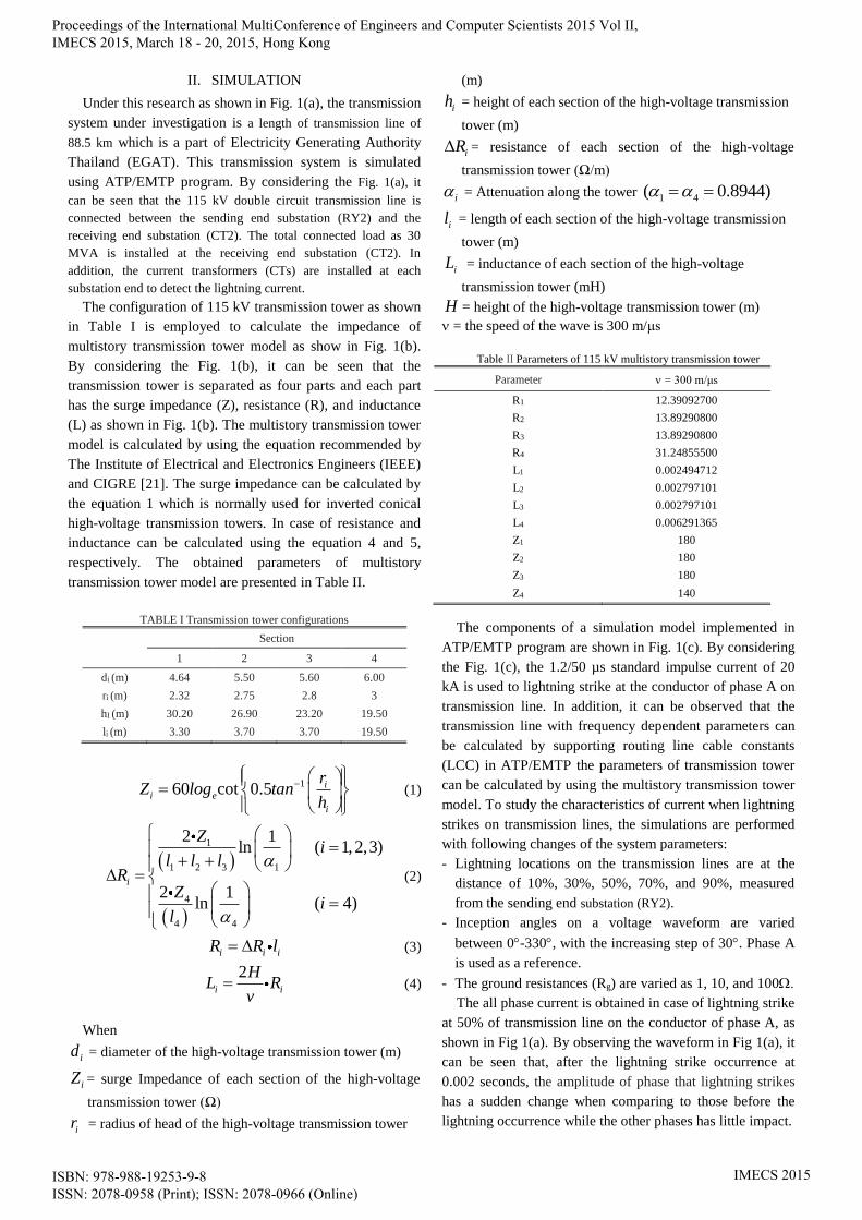
II. SIMULATION
Under this research as shown in Fig. 1(a), the transmission
system under investigation is a length of transmission line of
88.5 km which is a part of Electricity Generating Authority
Thailand (EGAT). This transmission system is simulated
using ATP/EMTP program. By considering the Fig. 1(a), it
can be seen that the 115 kV double circuit transmission line is
connected between the sending end substation (RY2) and the
receiving end substation (CT2). The total connected load as 30
MVA is installed at the receiving end substation (CT2). In
addition, the current transformers (CTs) are installed at each
substation end to detect the lightning current.
The configuration of 115 kV transmission tower as shown
in Table I is employed to calculate the impedance of
multistory transmission tower model as show in Fig. 1(b).
By considering the Fig. 1(b), it can be seen that the
transmission tower is separated as four parts and each part
has the surge impedance (Z), resistance (R), and inductance
(L) as shown in Fig. 1(b). The multistory transmission tower
model is calculated by using the equation recommended by
The Institute of Electrical and Electronics Engineers (IEEE)
and CIGRE [21]. The surge impedance can be calculated by
the equation 1 which is normally used for inverted conical
high-voltage transmission towers. In case of resistance and
inductance can be calculated using the equation 4 and 5,
respectively. The obtained parameters of multistory
transmission tower model are presented in Table II.
TABLE I Transmission tower configurations
Section
1 2 3 4
di (m) 4.64 5.50 5.60 6.00
ri (m) 2.32 2.75 2.8 3
hI (m) 30.20 26.90 23.20 19.50
li (m) 3.30 3.70 3.70 19.50
160 cot 0.5 i
i e
i
rZ log tan
h
(1)
1
1 2 3 1
4
4 4
2 1ln ( 1, 2,3)
2 1ln ( 4)
i
Zi
l l lR
Zi
l
(2)
i i iR R l (3)
2
i i
HL R
v (4)
When
id = diameter of the high-voltage transmission tower (m)
iZ = surge Impedance of each section of the high-voltage
transmission tower (Ω)
ir = radius of head of the high-voltage transmission tower
(m)
ih = height of each section of the high-voltage transmission
tower (m)
iR = resistance of each section of the high-voltage
transmission tower (Ω/m)
i = Attenuation along the tower 1 4( 0.8944)
il = length of each section of the high-voltage transmission
tower (m)
iL = inductance of each section of the high-voltage
transmission tower (mH)
H = height of the high-voltage transmission tower (m)
= the speed of the wave is 300 m/μs
Table II Parameters of 115 kV multistory transmission tower
Parameter = 300 m/μs
R1 12.39092700
R2 13.89290800
R3 13.89290800
R4 31.24855500
L1 0.002494712
L2 0.002797101
L3 0.002797101
L4 0.006291365
Z1 180
Z2 180
Z3 180
Z4 140
The components of a simulation model implemented in
ATP/EMTP program are shown in Fig. 1(c). By considering
the Fig. 1(c), the 1.2/50 µs standard impulse current of 20
kA is used to lightning strike at the conductor of phase A on
transmission line. In addition, it can be observed that the
transmission line with frequency dependent parameters can
be calculated by supporting routing line cable constants
(LCC) in ATP/EMTP the parameters of transmission tower
can be calculated by using the multistory transmission tower
model. To study the characteristics of current when lightning
strikes on transmission lines, the simulations are performed
with following changes of the system parameters:
- Lightning locations on the transmission lines are at the
distance of 10%, 30%, 50%, 70%, and 90%, measured
from the sending end substation (RY2).
- Inception angles on a voltage waveform are varied
between 0-330, with the increasing step of 30. Phase A
is used as a reference.
- The ground resistances (Rg) are varied as 1, 10, and 100.
The all phase current is obtained in case of lightning strike
at 50% of transmission line on the conductor of phase A, as
shown in Fig 1(a). By observing the waveform in Fig 1(a), it
can be seen that, after the lightning strike occurrence at
0.002 seconds, the amplitude of phase that lightning strikes
has a sudden change when comparing to those before the
lightning occurrence while the other phases has little impact.
Proceedings of the International MultiConference of Engineers and Computer Scientists 2015 Vol II, IMECS 2015, March 18 - 20, 2015, Hong Kong
ISBN: 978-988-19253-9-8 ISSN: 2078-0958 (Print); ISSN: 2078-0966 (Online)
IMECS 2015
RY2
115 kV
CT CT
115 kV
CT2
30 MVA
PF 0.8 lag
88.5 km
(a) One line diagram of the simulation circuit
l1
l2
l3
l4
d1
d2
d3
d4
Rg
Z4
R4 L4
Z3
R3 L3
Z2
R2 L2
Z1
R1 L1
(b) Multistory transmission tower model (c) Simulation circuit model in ATP
Fig 1. Component model implemented in ATP simulation
Proceedings of the International MultiConference of Engineers and Computer Scientists 2015 Vol II, IMECS 2015, March 18 - 20, 2015, Hong Kong
ISBN: 978-988-19253-9-8 ISSN: 2078-0958 (Print); ISSN: 2078-0966 (Online)
IMECS 2015
0 0.005 0.01 0.015 0.02 0.025 0.03-1.5
-1
-0.5
0
0.5
1x 10
4
Time(s)
Cu
rren
t(A
)
IRY2
(A)
ICT2
(A)
ICT2
(A) IRY2
(A)
0 0.005 0.01 0.015 0.02 0.025 0.03-1.5
-1
-0.5
0
0.5
1x 10
4
Time(s)
Cu
rren
t(A
)
IRY2
(A)
ICT2
(A)
ICT2
(A) IRY2
(A)
(a) lightning strike occurs at 10% of transmission line (b) lightning strike occurs at 30% of transmission line
0 0.005 0.01 0.015 0.02 0.025 0.03-1.5
-1
-0.5
0
0.5
1x 10
4
Time(s)
Cu
rren
t(A
)
IRY2
(A)
ICT2
(A)
IRY2
(A)ICT2
(A)
0 0.005 0.01 0.015 0.02 0.025 0.03-1.5
-1
-0.5
0
0.5
1x 10
4
Time(s)
Cu
rren
t(A
)
IRY2
(A)
ICT2
(A)
ICT2
(A) IRY2
(A)
(c) lightning strike occurs at 50% of transmission line (d) lightning strike occurs at 70% of transmission line
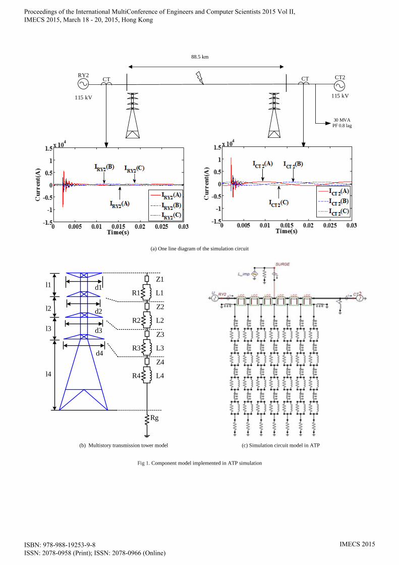
Fig. 2. Current Waveform for various lengths of the transmission lines that lightning strike occurs
III. RESULTS AND DISCUSSION
After simulating the lightning strikes when the
location of lightning is varied along the length of
transmission line, the example the current of phase A
waveforms at the each substation is illustrated in Fig.
2. By observing Fig. 2, the similarity between these
current waveforms can be seen obviously but the
amplitude and the first peak time in these figures can
be seen in Table III.
Table III Peak amplitude and first peak time of transient current for various
lengths of the transmission lines that lightning strike occurs
Location of
Lightning
Peak amplitude of Phase A (kA) First peak time (ms)
RY2 CT2 RY2 CT2
10% -12.710 8.022 2.033 2.280
30% -11.266 8.479 2.082 2.233
50% -9.819 9.470 2.158 2.158
70% -9.022 10.587 2.219 2.096
By carefully considering the Fig. 2(a) and Table III,
For the location of lightning strikes occurring at the 10% of
length of the transmission line, it is found that, during the
post-lightning condition at 2 ms, the amplitude of phase that
lightning strikes has a change of more than 5 times of a
normal condition and its change plays an important role in
the abnormal detection decision algorithm. Based on a
further behaviour of Table III, when location of lightning
strike on the transmission line is varied and inception angles
do not change, it is noticed that the peak amplitude of phase
that lightning strikes decrease when increasing distance
between the sending end substation and the lightning
location as shown in Table III. Since the impedance between
the sending end substation and the location of lightning
strike tend to increase. The peak amplitude current measure
at sending end of substation are decrease due to impedance
in transmission line. Moreover, the first peak time is also
considered when location of lightning strike on the
transmission line is varied. It is found that the first peak time
tends to increase when increasing distance between the
sending end substation and the lightning location. This
indicates that the first peak time can be beneficial for
locating the lightning strike on the transmission line.
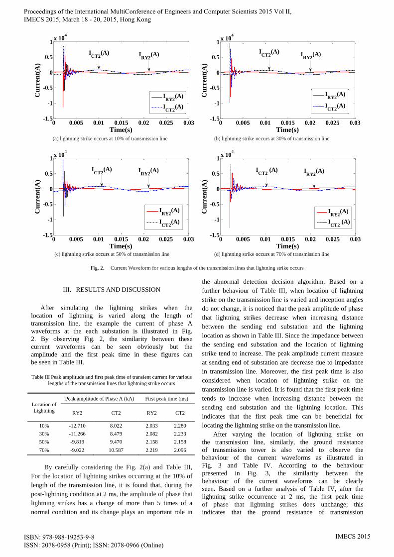
After varying the location of lightning strike on
the transmission line, similarly, the ground resistance
of transmission tower is also varied to observe the
behaviour of the current waveforms as illustrated in
Fig. 3 and Table IV. According to the behaviour
presented in Fig. 3, the similarity between the
behaviour of the current waveforms can be clearly
seen. Based on a further analysis of Table IV, after the
lightning strike occurrence at 2 ms, the first peak time
of phase that lightning strikes does unchange; this
indicates that the ground resistance of transmission
Proceedings of the International MultiConference of Engineers and Computer Scientists 2015 Vol II, IMECS 2015, March 18 - 20, 2015, Hong Kong
ISBN: 978-988-19253-9-8 ISSN: 2078-0958 (Print); ISSN: 2078-0966 (Online)
IMECS 2015
tower is treated as a no-impact, but the amplitude of
phase that lightning strikes has a little decrease when
increasing the ground resistance of transmission tower.
0 0.005 0.01 0.015 0.02 0.025 0.03-1.5
-1
-0.5
0
0.5
1
x 104
Time(s)
Cu
rren
t(A
)
Ground resistance 1 ohm
IRY2
ICT2
(a) ground resistance is 1 Ohm.
0 0.005 0.01 0.015 0.02 0.025 0.03-1.5
-1
-0.5
0
0.5
1
x 104
Time(s)
Cu
rren
t(A
)
Ground resistance 10 ohm
IRY2
ICT2
(b) ground resistance is 10 Ohms.
0 0.005 0.01 0.015 0.02 0.025 0.03-1.5
-1
-0.5
0
0.5
1
x 104
Time(s)
Cu
rren
t(A
)
Ground resistance 100 ohm
IRY2
ICT2
(c) ground resistance is 100 Ohm.
Fig. 3. Current Waveform for various ground resistances of the
transmission tower that lightning strike occurs.
TABLE IV Peak amplitude and first peak time of transient current for
various ground resistances of the transmission tower that lightning strike
occurs
Ground
Resistance (Ω) Peak amplitude of Phase A (kA) First peak time (ms)
RY2 CT2 RY2 CT2
1 -9.048 10.619 2.219 2.096
10 -9.021 10.587 2. 219 2.096
100 -8.825 10.364 2. 219 2.096
IV. CONCLUSION
In this paper, the characteristics of the peak amplitude
current and the first peak time obtained from the current
waveforms during lightning striking on the transmission
system have been analyzed the lightning has often struck on
the transmission system so it is necessary to understand
variation of current waveforms before doing decision
algorithm. The transmission system is chosen based on the
115 kV Thailand’s transmission and distribution system. The
current waveforms are obtained from transient simulator
using the EMTP/ATPDraw program. The LCC model is
used for calculating the transmission line with frequency
dependent parameters while the multistory model is used for
calculating the parameters of transmission tower. To study
the characteristics of current during lightning strike
occurrence on the transmission lines, the lightning location
and the ground resistance of transmission tower are varied.
By performing many simulations, it has been found that,
when location of lightning strike on the transmission line is
varied, the both amplitude and time have a change in
accordance with the location of lightning; its change plays
an important role in the abnormal detection decision
algorithm and lightning location algorithm. On the other
hand, when ground resistance of transmission tower is
varied, the amplitude only has a little change; this indicates
that the abnormal detection decision algorithm can be
beneficial. The further work will be development of the
lightning location algorithm using discrete wavelet
transform.
ACKNOWLEDGMENT
The authors wish to gratefully acknowledge financial
support for this research from the King Mongkut’s Institute
of Technology Ladkrabang Research fund, Thailand
REFERENCES
[1] L.Grcev, M. Popov, “On high-frequency circuit equivalents of a
vertical ground rod,” IEEE Trans. Power Del., vol. 20, no. 2, pp.
1598-1603, Apr. 2005.
[2] P. N. Mikropoulos and T. E. Tsovilis, “Estimation of the shielding
performance of overhead transmission lines: the effects of lightning
attachment model and lightning crest current distribution,” IEEE
Trans. Dielectr. Electr. Insul., vol. 19, no. 6, pp. 2155-2164, Dec.
2012.
[3] T. Suzuki, K. Miyake and T. Shindo, “Discharge path model in
model test of lightning strokes to tall mast,” IEEE Trans. Power App.
Syst., vol. PAS-100, pp. 3553-3562, Jul. 1981.
[4] A. Borghetti, C. A. Nucci, and M. Paolone, “Estimation of the
statistical distributions of lightning current parameters at ground level
from the data recorded by instrumented towers,” IEEE Trans. Power
Del., Vol. 19, pp. 1400-1409, Jul. 2004.
[5] J. G. Anderson, Transmission Line Reference Book – 345 kV and
Above, 2nd ed. Palo Alto, CA: Electric Power Research Institute,
1982, ch. 12
[6] A. J. Eriksson, “An improved electrogeometric model for
transmission line shielding analysis,” IEEE Trans. Power Del., Vol.
2, pp. 871-886, Jul. 1987.
[7] H. R. Armstrong and E. R. Whitehead, “Field and analytical studies
of transmission line shielding,” IEEE Trans. Power App. Syst., vol.
87, pp. 270-281, May 1968.
[8] C. F. Wagner and A. R. Hileman, “The lightning stroke-II,” AIEE
Trans. Power App. Syst., vol. 80, no. 3, pp. 622-642, Apr 1961.
Proceedings of the International MultiConference of Engineers and Computer Scientists 2015 Vol II, IMECS 2015, March 18 - 20, 2015, Hong Kong
ISBN: 978-988-19253-9-8 ISSN: 2078-0958 (Print); ISSN: 2078-0966 (Online)
IMECS 2015

[9] A. M. Mousa and K. D. Srivastava, “A revised electrogeometric
model for the termination of lightning strokes on ground objects,”
Int’l. Aerosp. Ground Conf. Lightning and Static Electricity,
Oklahoma City, OK, USA, pp. 324-352, 1988.
[10] Jun Takami, “Observational Results of Lightning Current on
Transmission Towers,” IEEE Trans. Power Del., vol. 22, no. 1, Jan
2007.
[11] L. Dellera and E. Garbagnati, “Lightning stroke simulation by means
of the leader progression model,” IEEE Trans. Power Del., Vol. 5,
no. 4, pp. 2009-2029, Oct 1990.
[12] J. He, Y. Tu, R. Zeng, J. B. Lee, S. H. Chang, and Z. Guan, “Numeral
analysis model for shielding failure of transmission line under
lightning stroke,” IEEE Trans. Power Del., Vol. 20, no. 2, pp. 815-
822, Apr 2005.
[13] B. Vahidi, M. Yahyaabadi, M. R. B. Tavakoli, and S. M. Ahadi,
“Leader progression analysis model for shielding failure computation
by using the charge simulation method,” IEEE Trans. Power Del.,
Vol. 23, no. 4, pp. 2201-2206, Oct 2008.
[14] B. Wei, Z. Fu, and H. Yuan “Analysis of lightning shielding failure
for 500- kV overhead transmission lines based on an improved leader
progression model”, IEEE Trans. Power Del., Vol. 24, no. 3, pp.
1433-1440, Jul 2009.
[15] M. R. B. Tavakoli and B. Vahidi, “Transmission-lines shielding
failure- rate calculation by means of 3-D leader progression models,”
IEEE Trans. Power Del., Vol. 26, no. 2 pp. 507-516, Mar 2011.
[16] Nattaya Klairuang, Witchuda Sopho, and Pisarn Densungnern,
“Lightning Performance Improvement of 22 kV Distribution Lines,”
Department of Electrical Engineering, Faculty of Engineering at
Sriracha, Kasetsart University Sriracha Campus
[17] Jordan C. A., “Lightning computation for transmission line with
overhead ground wires,” Gen. Elec. Rev., vol. 37, pp. 130-137, 1934.
[18] C.F. Wagner, A.R. Hileman, “A new approach to the calculation of
lightning performance of transmission line,” AIEE Trans., vol.79, no.
3 pp. 589-603, May 1960.
[19] Michael A. Sargent and Mat Darveniza, “Tower surge impedance,”
IEEE Trans. Power App. Syst., vol. PAS-88, no. 5, pp. 680-687, May
1969.
[20] Kohshi Okumura, “Surge Impedance of Transmission-line Towers: C.
A. Jordan’s Formula,” Elektrotehnički fakultet, 15, Sep 2010.
[21] A. Ametani, N. Nagaoka, T. Funabashi, N. Inoue, “Tower Structure
Effect on a Back-Flashover Phase,” Proc. of Int. Conf. on Power
Systems Transients (IPST’05), Paper No. IPST05 – 190, Montreal,
Canada, 19-23 June 2005.
[22] K.Fekete1, S. Nikolovski, G. Knezević, M. Stojkov, Z. Kovač,
“Simulation of Lightning Transients on 110 kV overhead-cable
transmission line using ATP-EMTP,” IEEE Mediterranean
Electrotechnical Conference, MELECON, 26-28 April 2010.
[23] C. Yao, H. Wu, Y. Long, Y. Mi, “A Novel Method to Locate a Fault
of Transmission Lines by Shielding Failure,” IEEE Trans. Dielectr.
Electr. Insul., vol. 21, no. 4, pp. 1573-1583, Aug 2014.
[24] “Estimating Lightning Performance of Transmission Lines II Updates
to Analytical models,” IEEE Working Group Report, 92 SM 453-1
PWRD.
[25] “Guide to Procedure for Estimating the Lightning Performance of
Transmission Lines,” CIGRE SC33-WG01 Report, Oct. 1991
BIOGRAPHIES
Prailkanok Lertwanitrot is currently a B.Eng.
candidate at the department of electrical engineering,
Faculty of Engineering, King Mongkut’s Institute of
Technology Ladkrabang. Her research interests are in
power system protection, lightning protection.
Patcharaporn kettranan is currently a B.Eng.
candidate at the department of electrical engineering,
Faculty of Engineering, King Mongkut’s Institute of
Technology Ladkrabang. Her research interests are in
power system protection, lightning protection.
Pimsiri itthisathienkul is currently a B.Eng.
candidate at the department of electrical engineering,
Faculty of Engineering, King Mongkut’s Institute of
Technology Ladkrabang. Her research interests are in
power system protection, lightning protection.
Atthapol Ngaopitakkul is currently a lecturer at the
department of electrical engineering, King
Mongkut’s Institute of Technology Laddrabang,
Bangkok, Thailand. His research interests are on
transmission systems and Protection Relay.
Proceedings of the International MultiConference of Engineers and Computer Scientists 2015 Vol II, IMECS 2015, March 18 - 20, 2015, Hong Kong
ISBN: 978-988-19253-9-8 ISSN: 2078-0958 (Print); ISSN: 2078-0966 (Online)
IMECS 2015


![[PPT]Direct – Current Motor Characteristics and … · Web viewDirect – Current Motor Characteristics and Applications Straight Shunt Motor Essentially a constant speed motor](https://img.pdfslide.us/doc/110x75/5add0e687f8b9a4a268d0073/pptdirect-current-motor-characteristics-and-viewdirect-current-motor.jpg)