Embed Size (px)
Citation preview
Metals 2012, 2, 122-135; doi:10.3390/met2020122
metalsISSN 2075-4701
www.mdpi.com/journal/metals/
Article
Characterisation and Mechanical Testing of Open Cell Al Foams Manufactured by Molten Metal Infiltration of Porous Salt Bead Preforms: Effect of Bead Size
Appichart Jinnapat and Andrew Kennedy *
Manufacturing Research Division, Faculty of Engineering, University of Nottingham,
Nottingham NG7 2RD, UK; E-Mail: [email protected]
* Author to whom correspondence should be addressed; E-Mail: [email protected];
Tel.: +44-115-9513744.
Received: 16 April 2012; in revised form: 17 May 2012 / Accepted: 28 May 2012 /
Published: 1 June 2012
Abstract: Preforms made from porous salt beads with different diameters (0.5–1.0, 1.4–2.0
and 2.5–3.1 mm) have been infiltrated with molten Al to produce porous structures using
pressure-assisted vacuum investment casting. Infiltration was incomplete for preforms with
high densities. At higher infiltration pressures, penetration of molten Al occurred into
beads of all sizes and was predicted using a simple model. The yield strength of the porous
structures increased with increasing density and decreasing pore (bead) size. Despite the
non-optimum distribution of metal in the porous structure, due to partial infiltration within
the beads, the magnitude and density dependence of the yield stress were comparable with
those for pure Al foams reported in similar studies. The structural efficiency was improved
for structures produced at lower infiltration pressure, where the metal is predominantly
distributed in the cell walls. The rate of salt dissolution from the preforms was high, in
particular for high density preforms, large beads and preforms infiltrated at low pressures,
owing to the ability of the porous beads to collapse as well as dissolve.
Keywords: porous metals; aluminium; liquid metal infiltration; mechanical testing
OPEN ACCESS

Metals 2012, 2 123
1. Introduction
Porous metals with open, connected cells are ideally suited to applications involving heat exchange
with a fluid which permeates the porous structure. The fraction of solid and the size of the pores in the
porous metal component are important not only for the thermal performance, but also the flow
behaviour of the fluid through it. For a given application, the structure of the porous metal must be
optimized to maximize its performance.
Infiltration processing offers a versatile and economical route to the production of porous metal
structures, where simple equipment is used and net shape can be obtained [1]. To do so involves four
steps: preparation of the leachable preform (usually NaCl for infiltration with Al); infiltration of
molten metal into the preform; solidification of the molten metal; and dissolution of the preform in a
solvent or water. The relative density of the foam can be controlled by varying the degree of
densification of the preform, most commonly by a combination of mechanical pressing and sintering,
where the resulting preform volume fraction is in the range of 0.64 to 0.9 [2]. The pore size is dictated
by the size of the leachable material.
Porous metals have been made using spherical space holders, manufactured by melting and in-flight
spheriodisation techniques [3] or by forming a paste made from fine salt particles mixed with flour and
water [4]. Porous metals with spherical pores have been found to be stronger and stiffer than their
counterparts with angular pores and this is especially marked for porous structures with small (75 μm)
pores. These structures with small pores are also significantly stronger than their counterparts with
large (400 μm) pores [2,3]. This difference in strength could not be completely accounted for by the
change in topology [2] and has been attributed to the formation of a hard, 100 nm thick, load-bearing
oxide layer on the cell surfaces during the salt leaching process. This oxide layer affects plastic flow in
the cell walls, the effect being marked for pore sizes below roughly 100 μm [5].
Previous studies by the authors [6,7] presented a process for the manufacture of porous spherical
beads by the disintegration, in oil, of a salt paste comprising fine salt powder, flour and water. The
work demonstrated how they can be used in the production of porous Al structures with a range of
solid fractions. Although only demonstrated for one bead size, the benefits of using porous beads
included the ability to infiltrate the preforms at low pressures, enabling production by simple and low
cost investment casting methods, the production of pores with good connectivity due to the efficient
packing of the spherical beads and, due to their porous nature, their rapid dissolution in warm water,
making the production of large components viable.
It was apparent from this study that infiltration of molten metal into the porous beads can occur,
particularly at higher infiltration pressures. As it is unlikely that this metal within the pores is load
bearing [3], it is unclear as to what effect this might have on their mechanical response. As an
extension to this previous work, this paper presents the structure and compressive mechanical
properties for porous Al made by the infiltration of preforms made from porous, spherical NaCl beads
with sizes ranging from 0.5 to 3.1 mm in diameter.
Metals 2012, 2 124
2. Results and Discussion
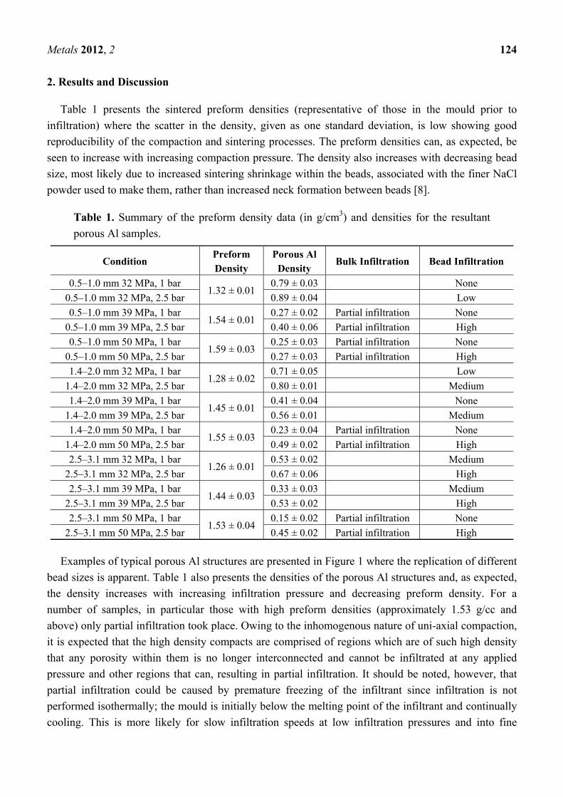
Table 1 presents the sintered preform densities (representative of those in the mould prior to
infiltration) where the scatter in the density, given as one standard deviation, is low showing good
reproducibility of the compaction and sintering processes. The preform densities can, as expected, be
seen to increase with increasing compaction pressure. The density also increases with decreasing bead
size, most likely due to increased sintering shrinkage within the beads, associated with the finer NaCl
powder used to make them, rather than increased neck formation between beads [8].
Table 1. Summary of the preform density data (in g/cm3) and densities for the resultant
porous Al samples.
Condition Preform Density
Porous Al Density
Bulk Infiltration Bead Infiltration
0.5–1.0 mm 32 MPa, 1 bar 1.32 ± 0.01
0.79 ± 0.03 None
0.5–1.0 mm 32 MPa, 2.5 bar 0.89 ± 0.04 Low
0.5–1.0 mm 39 MPa, 1 bar 1.54 ± 0.01
0.27 ± 0.02 Partial infiltration None
0.5–1.0 mm 39 MPa, 2.5 bar 0.40 ± 0.06 Partial infiltration High
0.5–1.0 mm 50 MPa, 1 bar 1.59 ± 0.03
0.25 ± 0.03 Partial infiltration None
0.5–1.0 mm 50 MPa, 2.5 bar 0.27 ± 0.03 Partial infiltration High
1.4–2.0 mm 32 MPa, 1 bar 1.28 ± 0.02
0.71 ± 0.05 Low
1.4–2.0 mm 32 MPa, 2.5 bar 0.80 ± 0.01 Medium
1.4–2.0 mm 39 MPa, 1 bar 1.45 ± 0.01
0.41 ± 0.04 None
1.4–2.0 mm 39 MPa, 2.5 bar 0.56 ± 0.01 Medium
1.4–2.0 mm 50 MPa, 1 bar 1.55 ± 0.03
0.23 ± 0.04 Partial infiltration None
1.4–2.0 mm 50 MPa, 2.5 bar 0.49 ± 0.02 Partial infiltration High
2.5–3.1 mm 32 MPa, 1 bar 1.26 ± 0.01
0.53 ± 0.02 Medium
2.5–3.1 mm 32 MPa, 2.5 bar 0.67 ± 0.06 High
2.5–3.1 mm 39 MPa, 1 bar 1.44 ± 0.03
0.33 ± 0.03 Medium
2.5–3.1 mm 39 MPa, 2.5 bar 0.53 ± 0.02 High
2.5–3.1 mm 50 MPa, 1 bar 1.53 ± 0.04
0.15 ± 0.02 Partial infiltration None
2.5–3.1 mm 50 MPa, 2.5 bar 0.45 ± 0.02 Partial infiltration High
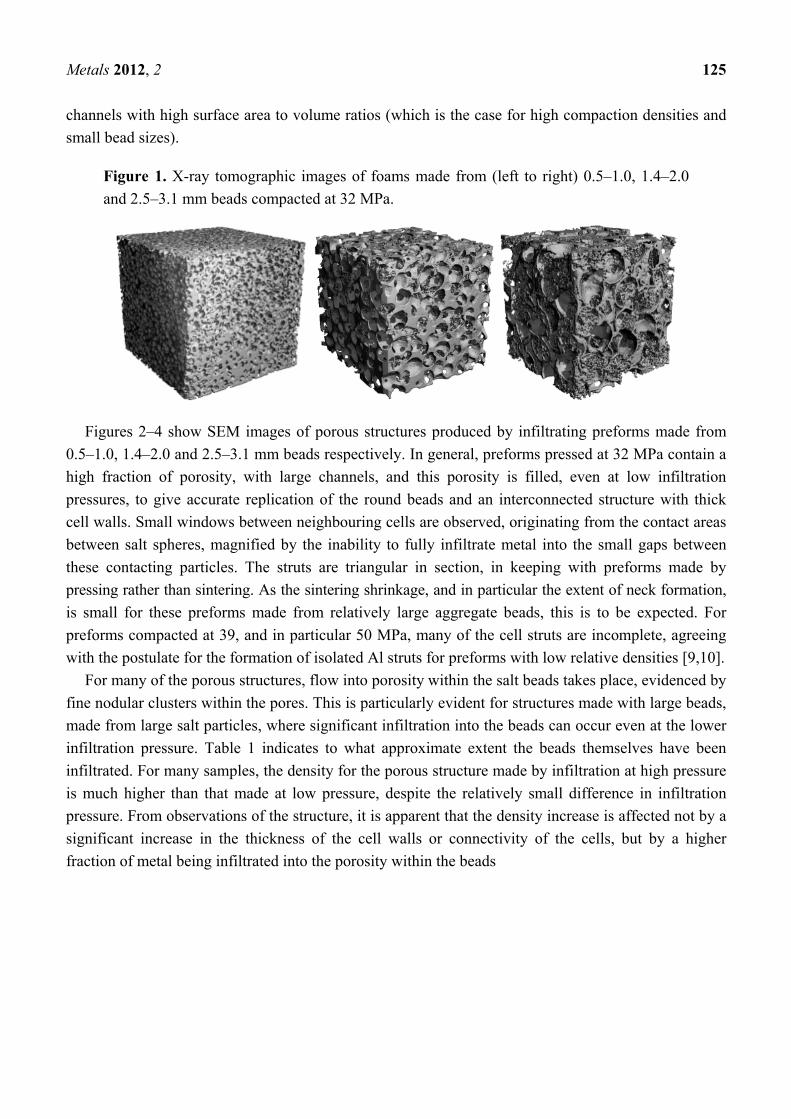
Examples of typical porous Al structures are presented in Figure 1 where the replication of different
bead sizes is apparent. Table 1 also presents the densities of the porous Al structures and, as expected,
the density increases with increasing infiltration pressure and decreasing preform density. For a
number of samples, in particular those with high preform densities (approximately 1.53 g/cc and
above) only partial infiltration took place. Owing to the inhomogenous nature of uni-axial compaction,
it is expected that the high density compacts are comprised of regions which are of such high density
that any porosity within them is no longer interconnected and cannot be infiltrated at any applied
pressure and other regions that can, resulting in partial infiltration. It should be noted, however, that
partial infiltration could be caused by premature freezing of the infiltrant since infiltration is not
performed isothermally; the mould is initially below the melting point of the infiltrant and continually
cooling. This is more likely for slow infiltration speeds at low infiltration pressures and into fine
Metals 2012, 2 125
channels with high surface area to volume ratios (which is the case for high compaction densities and
small bead sizes).
Figure 1. X-ray tomographic images of foams made from (left to right) 0.5–1.0, 1.4–2.0
and 2.5–3.1 mm beads compacted at 32 MPa.
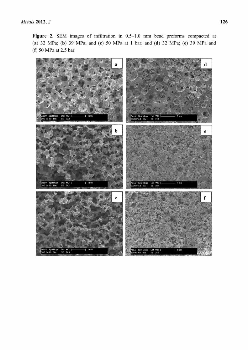
Figures 2–4 show SEM images of porous structures produced by infiltrating preforms made from
0.5–1.0, 1.4–2.0 and 2.5–3.1 mm beads respectively. In general, preforms pressed at 32 MPa contain a
high fraction of porosity, with large channels, and this porosity is filled, even at low infiltration
pressures, to give accurate replication of the round beads and an interconnected structure with thick
cell walls. Small windows between neighbouring cells are observed, originating from the contact areas
between salt spheres, magnified by the inability to fully infiltrate metal into the small gaps between
these contacting particles. The struts are triangular in section, in keeping with preforms made by
pressing rather than sintering. As the sintering shrinkage, and in particular the extent of neck formation,
is small for these preforms made from relatively large aggregate beads, this is to be expected. For
preforms compacted at 39, and in particular 50 MPa, many of the cell struts are incomplete, agreeing
with the postulate for the formation of isolated Al struts for preforms with low relative densities [9,10].
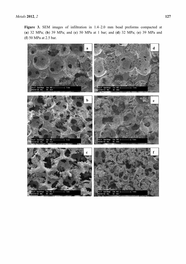
For many of the porous structures, flow into porosity within the salt beads takes place, evidenced by
fine nodular clusters within the pores. This is particularly evident for structures made with large beads,
made from large salt particles, where significant infiltration into the beads can occur even at the lower
infiltration pressure. Table 1 indicates to what approximate extent the beads themselves have been
infiltrated. For many samples, the density for the porous structure made by infiltration at high pressure
is much higher than that made at low pressure, despite the relatively small difference in infiltration
pressure. From observations of the structure, it is apparent that the density increase is affected not by a
significant increase in the thickness of the cell walls or connectivity of the cells, but by a higher
fraction of metal being infiltrated into the porosity within the beads
Metals 2012, 2 126
Figure 2. SEM images of infiltration in 0.5–1.0 mm bead preforms compacted at
(a) 32 MPa; (b) 39 MPa; and (c) 50 MPa at 1 bar; and (d) 32 MPa; (e) 39 MPa and
(f) 50 MPa at 2.5 bar.
a d
f
e
c
b
Metals 2012, 2 127
Figure 3. SEM images of infiltration in 1.4–2.0 mm bead preforms compacted at
(a) 32 MPa; (b) 39 MPa; and (c) 50 MPa at 1 bar; and (d) 32 MPa; (e) 39 MPa and
(f) 50 MPa at 2.5 bar.
a d
f
e
c
b
Metals 2012, 2 128
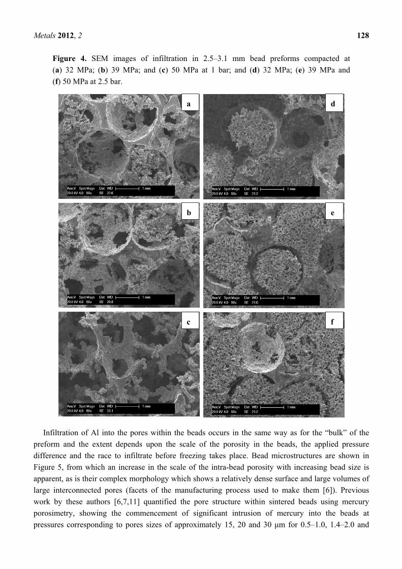
Figure 4. SEM images of infiltration in 2.5–3.1 mm bead preforms compacted at
(a) 32 MPa; (b) 39 MPa; and (c) 50 MPa at 1 bar; and (d) 32 MPa; (e) 39 MPa and
(f) 50 MPa at 2.5 bar.
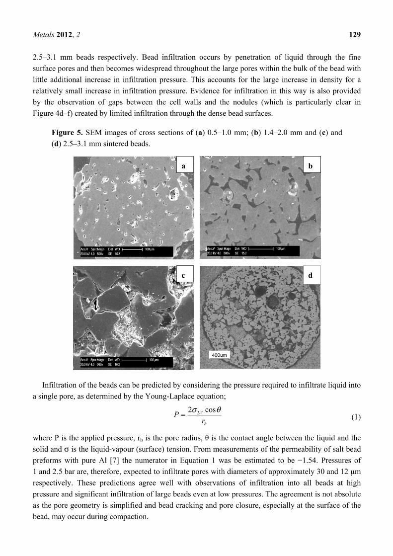
Infiltration of Al into the pores within the beads occurs in the same way as for the “bulk” of the
preform and the extent depends upon the scale of the porosity in the beads, the applied pressure
difference and the race to infiltrate before freezing takes place. Bead microstructures are shown in
Figure 5, from which an increase in the scale of the intra-bead porosity with increasing bead size is
apparent, as is their complex morphology which shows a relatively dense surface and large volumes of
large interconnected pores (facets of the manufacturing process used to make them [6]). Previous
work by these authors [6,7,11] quantified the pore structure within sintered beads using mercury
porosimetry, showing the commencement of significant intrusion of mercury into the beads at
pressures corresponding to pores sizes of approximately 15, 20 and 30 μm for 0.5–1.0, 1.4–2.0 and
a d
f
e
c
b
Metals 2012, 2 129
2.5–3.1 mm beads respectively. Bead infiltration occurs by penetration of liquid through the fine
surface pores and then becomes widespread throughout the large pores within the bulk of the bead with
little additional increase in infiltration pressure. This accounts for the large increase in density for a
relatively small increase in infiltration pressure. Evidence for infiltration in this way is also provided
by the observation of gaps between the cell walls and the nodules (which is particularly clear in
Figure 4d–f) created by limited infiltration through the dense bead surfaces.
Figure 5. SEM images of cross sections of (a) 0.5–1.0 mm; (b) 1.4–2.0 mm and (c) and
(d) 2.5–3.1 mm sintered beads.
Infiltration of the beads can be predicted by considering the pressure required to infiltrate liquid into
a single pore, as determined by the Young-Laplace equation;
h
LV
rP
θσ cos2= (1)
where P is the applied pressure, rh is the pore radius, θ is the contact angle between the liquid and the
solid and σ is the liquid-vapour (surface) tension. From measurements of the permeability of salt bead
preforms with pure Al [7] the numerator in Equation 1 was be estimated to be −1.54. Pressures of
1 and 2.5 bar are, therefore, expected to infiltrate pores with diameters of approximately 30 and 12 μm
respectively. These predictions agree well with observations of infiltration into all beads at high
pressure and significant infiltration of large beads even at low pressures. The agreement is not absolute
as the pore geometry is simplified and bead cracking and pore closure, especially at the surface of the
bead, may occur during compaction.
a
c
b
d
Metals 2012, 2 130
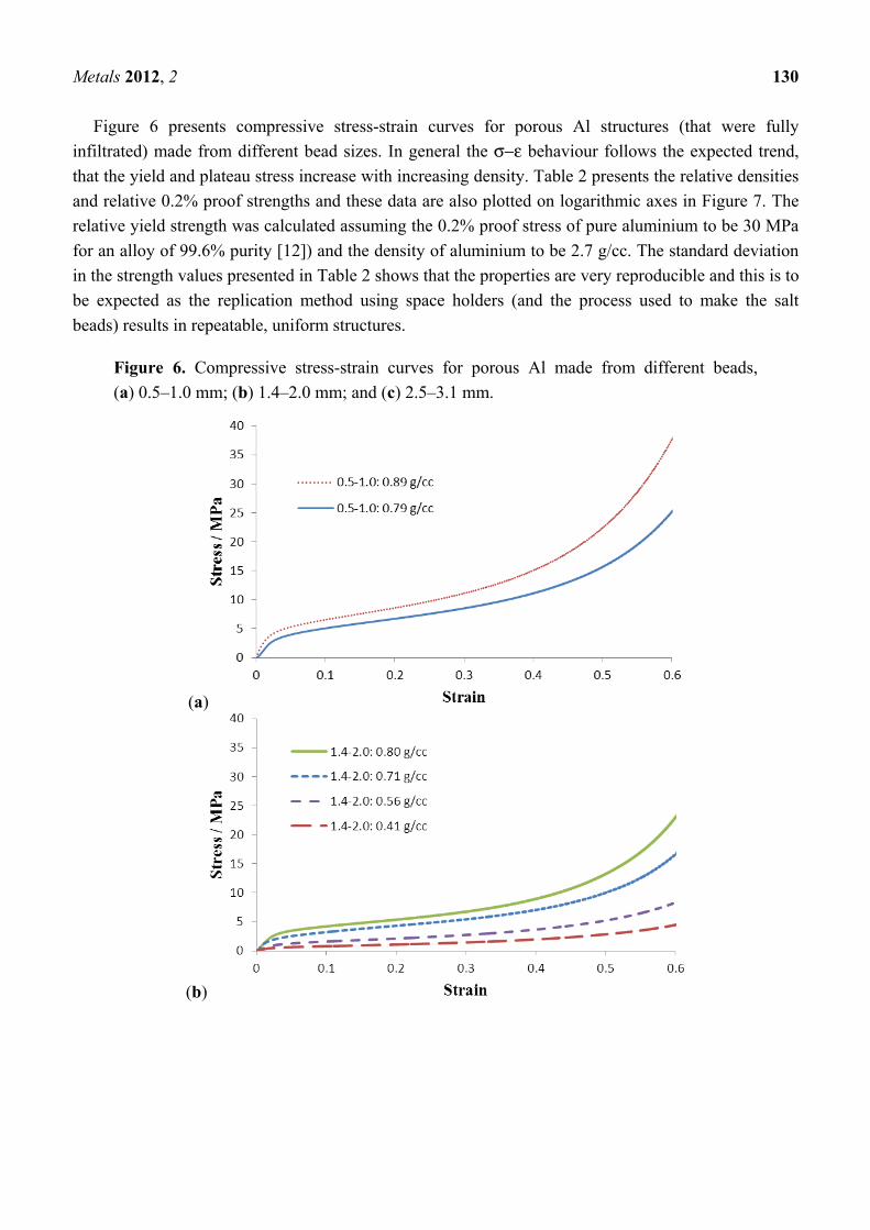
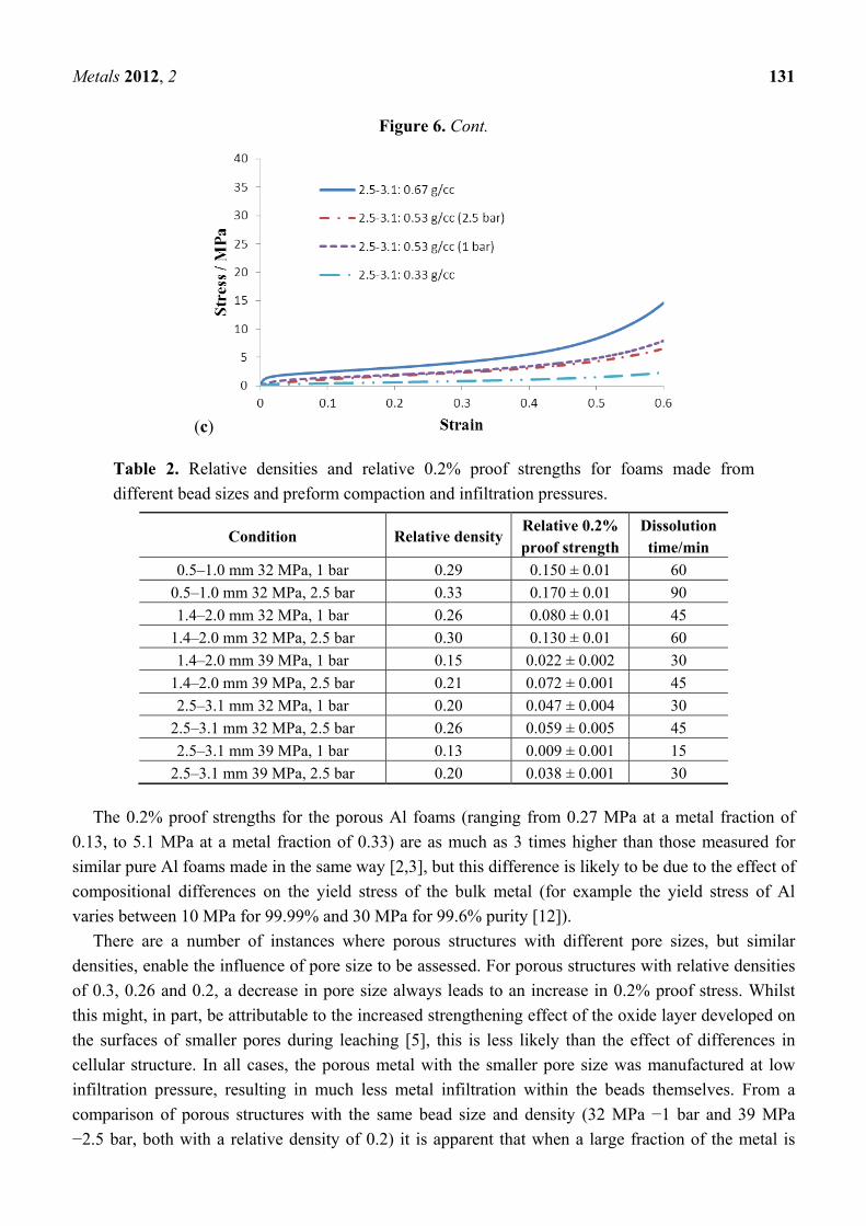
Figure 6 presents compressive stress-strain curves for porous Al structures (that were fully
infiltrated) made from different bead sizes. In general the σ−ε behaviour follows the expected trend,
that the yield and plateau stress increase with increasing density. Table 2 presents the relative densities
and relative 0.2% proof strengths and these data are also plotted on logarithmic axes in Figure 7. The
relative yield strength was calculated assuming the 0.2% proof stress of pure aluminium to be 30 MPa
for an alloy of 99.6% purity [12]) and the density of aluminium to be 2.7 g/cc. The standard deviation
in the strength values presented in Table 2 shows that the properties are very reproducible and this is to
be expected as the replication method using space holders (and the process used to make the salt
beads) results in repeatable, uniform structures.
Figure 6. Compressive stress-strain curves for porous Al made from different beads,
(a) 0.5–1.0 mm; (b) 1.4–2.0 mm; and (c) 2.5–3.1 mm.
(a)
(b)
Metals 2012, 2 131
Figure 6. Cont.
(c)
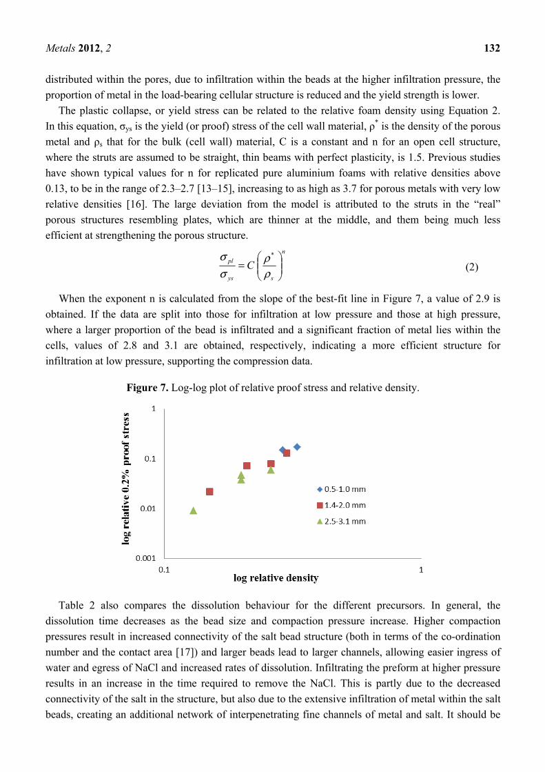
Table 2. Relative densities and relative 0.2% proof strengths for foams made from
different bead sizes and preform compaction and infiltration pressures.
Condition Relative density Relative 0.2% proof strength
Dissolution time/min
0.5–1.0 mm 32 MPa, 1 bar 0.29 0.150 ± 0.01 60
0.5–1.0 mm 32 MPa, 2.5 bar 0.33 0.170 ± 0.01 90
1.4–2.0 mm 32 MPa, 1 bar 0.26 0.080 ± 0.01 45
1.4–2.0 mm 32 MPa, 2.5 bar 0.30 0.130 ± 0.01 60
1.4–2.0 mm 39 MPa, 1 bar 0.15 0.022 ± 0.002 30
1.4–2.0 mm 39 MPa, 2.5 bar 0.21 0.072 ± 0.001 45
2.5–3.1 mm 32 MPa, 1 bar 0.20 0.047 ± 0.004 30
2.5–3.1 mm 32 MPa, 2.5 bar 0.26 0.059 ± 0.005 45
2.5–3.1 mm 39 MPa, 1 bar 0.13 0.009 ± 0.001 15
2.5–3.1 mm 39 MPa, 2.5 bar 0.20 0.038 ± 0.001 30
The 0.2% proof strengths for the porous Al foams (ranging from 0.27 MPa at a metal fraction of
0.13, to 5.1 MPa at a metal fraction of 0.33) are as much as 3 times higher than those measured for
similar pure Al foams made in the same way [2,3], but this difference is likely to be due to the effect of
compositional differences on the yield stress of the bulk metal (for example the yield stress of Al
varies between 10 MPa for 99.99% and 30 MPa for 99.6% purity [12]).
There are a number of instances where porous structures with different pore sizes, but similar
densities, enable the influence of pore size to be assessed. For porous structures with relative densities
of 0.3, 0.26 and 0.2, a decrease in pore size always leads to an increase in 0.2% proof stress. Whilst
this might, in part, be attributable to the increased strengthening effect of the oxide layer developed on
the surfaces of smaller pores during leaching [5], this is less likely than the effect of differences in
cellular structure. In all cases, the porous metal with the smaller pore size was manufactured at low
infiltration pressure, resulting in much less metal infiltration within the beads themselves. From a
comparison of porous structures with the same bead size and density (32 MPa −1 bar and 39 MPa
−2.5 bar, both with a relative density of 0.2) it is apparent that when a large fraction of the metal is
Metals 2012, 2 132
distributed within the pores, due to infiltration within the beads at the higher infiltration pressure, the
proportion of metal in the load-bearing cellular structure is reduced and the yield strength is lower.
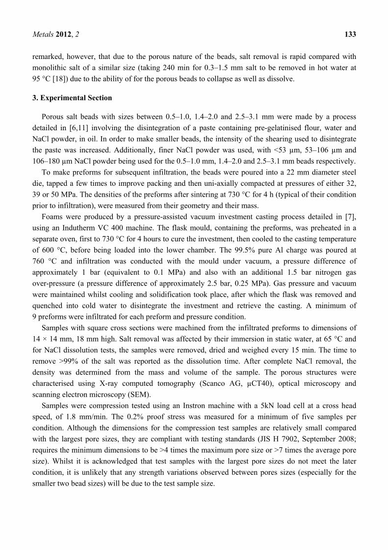
The plastic collapse, or yield stress can be related to the relative foam density using Equation 2.
In this equation, σys is the yield (or proof) stress of the cell wall material, ρ* is the density of the porous
metal and ρs that for the bulk (cell wall) material, C is a constant and n for an open cell structure,
where the struts are assumed to be straight, thin beams with perfect plasticity, is 1.5. Previous studies
have shown typical values for n for replicated pure aluminium foams with relative densities above
0.13, to be in the range of 2.3–2.7 [13–15], increasing to as high as 3.7 for porous metals with very low
relative densities [16]. The large deviation from the model is attributed to the struts in the “real”
porous structures resembling plates, which are thinner at the middle, and them being much less
efficient at strengthening the porous structure. n
sys
pl C
=
ρρ
σσ *
(2)
When the exponent n is calculated from the slope of the best-fit line in Figure 7, a value of 2.9 is
obtained. If the data are split into those for infiltration at low pressure and those at high pressure,
where a larger proportion of the bead is infiltrated and a significant fraction of metal lies within the
cells, values of 2.8 and 3.1 are obtained, respectively, indicating a more efficient structure for
infiltration at low pressure, supporting the compression data.
Figure 7. Log-log plot of relative proof stress and relative density.
Table 2 also compares the dissolution behaviour for the different precursors. In general, the
dissolution time decreases as the bead size and compaction pressure increase. Higher compaction
pressures result in increased connectivity of the salt bead structure (both in terms of the co-ordination
number and the contact area [17]) and larger beads lead to larger channels, allowing easier ingress of
water and egress of NaCl and increased rates of dissolution. Infiltrating the preform at higher pressure
results in an increase in the time required to remove the NaCl. This is partly due to the decreased
connectivity of the salt in the structure, but also due to the extensive infiltration of metal within the salt
beads, creating an additional network of interpenetrating fine channels of metal and salt. It should be
Metals 2012, 2 133
remarked, however, that due to the porous nature of the beads, salt removal is rapid compared with
monolithic salt of a similar size (taking 240 min for 0.3–1.5 mm salt to be removed in hot water at
95 °C [18]) due to the ability of for the porous beads to collapse as well as dissolve.
3. Experimental Section
Porous salt beads with sizes between 0.5–1.0, 1.4–2.0 and 2.5–3.1 mm were made by a process
detailed in [6,11] involving the disintegration of a paste containing pre-gelatinised flour, water and
NaCl powder, in oil. In order to make smaller beads, the intensity of the shearing used to disintegrate
the paste was increased. Additionally, finer NaCl powder was used, with <53 µm, 53–106 µm and
106–180 µm NaCl powder being used for the 0.5–1.0 mm, 1.4–2.0 and 2.5–3.1 mm beads respectively.
To make preforms for subsequent infiltration, the beads were poured into a 22 mm diameter steel
die, tapped a few times to improve packing and then uni-axially compacted at pressures of either 32,
39 or 50 MPa. The densities of the preforms after sintering at 730 °C for 4 h (typical of their condition
prior to infiltration), were measured from their geometry and their mass.
Foams were produced by a pressure-assisted vacuum investment casting process detailed in [7],
using an Indutherm VC 400 machine. The flask mould, containing the preforms, was preheated in a
separate oven, first to 730 °C for 4 hours to cure the investment, then cooled to the casting temperature
of 600 °C, before being loaded into the lower chamber. The 99.5% pure Al charge was poured at
760 °C and infiltration was conducted with the mould under vacuum, a pressure difference of
approximately 1 bar (equivalent to 0.1 MPa) and also with an additional 1.5 bar nitrogen gas
over-pressure (a pressure difference of approximately 2.5 bar, 0.25 MPa). Gas pressure and vacuum
were maintained whilst cooling and solidification took place, after which the flask was removed and
quenched into cold water to disintegrate the investment and retrieve the casting. A minimum of
9 preforms were infiltrated for each preform and pressure condition.
Samples with square cross sections were machined from the infiltrated preforms to dimensions of
14 × 14 mm, 18 mm high. Salt removal was affected by their immersion in static water, at 65 °C and
for NaCl dissolution tests, the samples were removed, dried and weighed every 15 min. The time to
remove >99% of the salt was reported as the dissolution time. After complete NaCl removal, the
density was determined from the mass and volume of the sample. The porous structures were
characterised using X-ray computed tomography (Scanco AG, µCT40), optical microscopy and
scanning electron microscopy (SEM).
Samples were compression tested using an Instron machine with a 5kN load cell at a cross head
speed, of 1.8 mm/min. The 0.2% proof stress was measured for a minimum of five samples per
condition. Although the dimensions for the compression test samples are relatively small compared
with the largest pore sizes, they are compliant with testing standards (JIS H 7902, September 2008;
requires the minimum dimensions to be >4 times the maximum pore size or >7 times the average pore
size). Whilst it is acknowledged that test samples with the largest pore sizes do not meet the later
condition, it is unlikely that any strength variations observed between pores sizes (especially for the
smaller two bead sizes) will be due to the test sample size.
Metals 2012, 2 134
4. Conclusions
Preforms made from porous salt beads with different diameters (0.5–1.0, 1.4–2.0 and 2.5–3.1 mm)
have been infiltrated with molten Al to produce porous structures using pressure-assisted vacuum
investment casting. Infiltration was incomplete for preforms with high densities. At higher infiltration
pressures, penetration of molten Al occurred into beads of all sizes. The infiltration behaviour within
the beads was predicted using a simple model.
The yield strength of the porous structures increased with increasing density and decreasing pore
(bead) size. Despite the non-optimum distribution of metal in the porous structure, due to partial
infiltration within the beads, the magnitude and density dependence of the yield stress were
comparable with those for pure Al foams reported in similar studies. The structural efficiency was
improved for structures produced at lower infiltration pressure, where the metal is predominantly
distributed in the cell walls.
The rate of salt dissolution from the preforms was high, in particular for high density preforms,
large beads and preforms infiltrated at low pressures, owing to the ability of the porous beads to
collapse as well as dissolve.
Acknowledgments
Appichart Jinnapat would like to thank the Royal Thai Air Force for financial support.
References
1 Sun, D.; Zhao, Y. Static and dynamic energy absorption of Al foams produced by the sintering
and dissolution process. Metal. Mater. Trans. B 2003, 34, 69–74.
2 Goodall, R.; Despois, J.F.; Marmottant, A.; Salvo, L.; Mortensen, A. The effect of preform
processing on replicated aluminium foam structure and mechanical properties. Scripta Mater.
2006, 54, 2069–2073.
3 Goodall, R.; Marmottant, A.; Salvo, L.; Mortensen, A. Spherical pore replicated microcellular
aluminium: Processing and influence on properties. Mater. Sci. Eng. A 2007, 465, 124–135.
4 Goodall, R.; Mortensen, A. Microcellular aluminium: Child’s play. Adv. Eng. Mater. 2007, 9,
951–954.
5 Diologent, F.; Goodall, R.; Mortensen, A. Surface oxide in replicated microcellular aluminium
and its influence on the plasticity size effect. Acta Mater. 2009, 57, 286–294.
6 Jinnapat, A.; Kennedy, A.R. The manufacture of spherical salt beads and their use as dissolvable
templates for the production of cellular solids via a powder metallurgy route. J. Alloys Compd.
2010, 499, 43–47.
7 Jinnapat, A.; Kennedy, A.R. The manufacture and characterization of aluminum foams made by
investment casting using dissolvable spherical sodium chloride bead performs. Metals 2011, 1,
49–64.
8 Goodall, R.; Despois, J.F.; Mortensen, A. Sintering of NaCl powder: Mechanisms and first stage
kinetics. J. Eur. Ceram. Soc. 2006, 26, 3487–3497.
Metals 2012, 2 135
9 Hao, G.; Han, F.; Li, W. Processing and mechanical properties of magnesium foams. J. Porous
Mater. 2009, 16, 251–256.
10 Zhao, Y.Y.; Sun, D.X. A novel sintering-dissolution process for manufacturing Al foams. Scripta
Mater. 2001, 44, 105–110.
11 Jinnapat, A. The Manufacture and Characterisation of Aluminium Foams Made by Investment
Casting Using Dissolvable Spherical Sodium Chloride Bead Performs. Ph.D. Thesis. University
of Nottingham, Nottingham, UK, September 2011.
12 Hatch, J.E. Aluminum: Properties and Physical Metallurgy; Aluminum Association Inc. and ASM
International: Metals Park, OH, USA, 1984.
13 San Marchi, C.; Mortensen, A. Deformation of open-cell aluminum foam. Acta Mater. 2001, 49,
3959–3969.
14 Despois, J.-F.; Mueller, R.; Mortensen, A. Uniaxial deformation of microcellular metals. Acta
Mater. 2006, 54, 4129–4142.
15 Diologent, F.; Combaz, E.; Laporte, V.; Goodall, R.; Weber, L.; Duc, F.; Mortensen, A.
Processing of Ag-Cu alloy foam by the replication process. Scripta Mater. 2009, 61, 351–354.
16 Amsterdam, E.; Goodall, R.; Mortensen, A.; Onck, P.R.; de Hosson, J.T.M. Fracture behavior of
low-density replicated aluminum alloy foams. Mater. Sci. Eng. A 2008, 496, 376–382.
17 Marmottant, A.; Salvo, L.; Martin, C.L.; Mortensen, A. Coordination measurements in compacted
NaCl irregular powders using X-ray microtomography. J. Eur. Ceram. Soc. 2008, 28, 2441–2449.
18 Zhao, Y.; Han, F.; Fung, T. Optimisation of compaction and liquid-state sintering in sintering and
dissolution process for manufacturing Al foams. Mater. Sci. Eng. A 2004, 364, 117–125.
© 2012 by the authors; licensee MDPI, Basel, Switzerland. This article is an open access article
distributed under the terms and conditions of the Creative Commons Attribution license
(http://creativecommons.org/licenses/by/3.0/).