Embed Size (px)
Citation preview

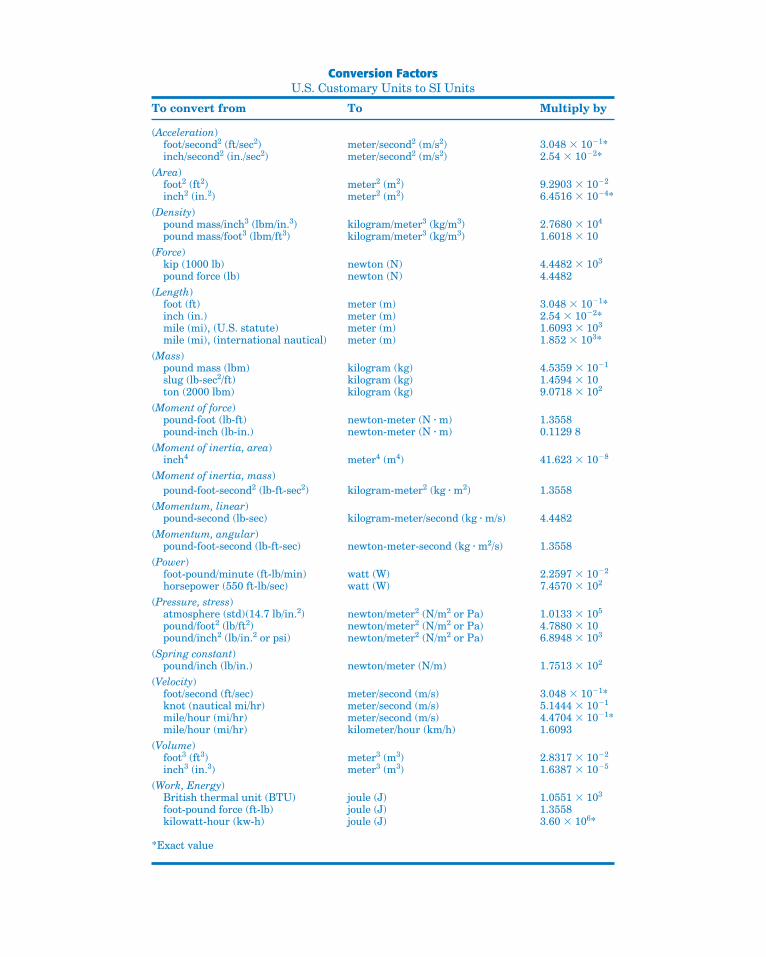
Conversion FactorsU.S. Customary Units to SI Units
To convert from To Multiply by
(Acceleration)foot/second2 (ft/sec2) meter/second2 (m/s2) 3.048 � 10�1*inch/second2 (in./sec2) meter/second2 (m/s2) 2.54 � 10�2*
(Area)foot2 (ft2) meter2 (m2) 9.2903 � 10�2
inch2 (in.2) meter2 (m2) 6.4516 � 10�4*(Density)
pound mass/inch3 (lbm/in.3) kilogram/meter3 (kg/m3) 2.7680 � 104
pound mass/foot3 (lbm/ft3) kilogram/meter3 (kg/m3) 1.6018 � 10(Force)
kip (1000 lb) newton (N) 4.4482 � 103
pound force (lb) newton (N) 4.4482(Length)
foot (ft) meter (m) 3.048 � 10�1*inch (in.) meter (m) 2.54 � 10�2*mile (mi), (U.S. statute) meter (m) 1.6093 � 103
mile (mi), (international nautical) meter (m) 1.852 � 103*(Mass)
pound mass (lbm) kilogram (kg) 4.5359 � 10�1
slug (lb-sec2/ft) kilogram (kg) 1.4594 � 10ton (2000 lbm) kilogram (kg) 9.0718 � 102
(Moment of force)pound-foot (lb-ft) newton-meter (N � m) 1.3558pound-inch (lb-in.) newton-meter (N � m) 0.1129 8
(Moment of inertia, area)inch4 meter4 (m4) 41.623 � 10�8
(Moment of inertia, mass)pound-foot-second2 (lb-ft-sec2) kilogram-meter2 (kg � m2) 1.3558
(Momentum, linear)pound-second (lb-sec) kilogram-meter/second (kg � m/s) 4.4482
(Momentum, angular)pound-foot-second (lb-ft-sec) newton-meter-second (kg � m2/s) 1.3558
(Power)foot-pound/minute (ft-lb/min) watt (W) 2.2597 � 10�2
horsepower (550 ft-lb/sec) watt (W) 7.4570 � 102
(Pressure, stress)atmosphere (std)(14.7 lb/in.2) newton/meter2 (N/m2 or Pa) 1.0133 � 105
pound/foot2 (lb/ft2) newton/meter2 (N/m2 or Pa) 4.7880 � 10pound/inch2 (lb/in.2 or psi) newton/meter2 (N/m2 or Pa) 6.8948 � 103
(Spring constant)pound/inch (lb/in.) newton/meter (N/m) 1.7513 � 102
(Velocity)foot/second (ft/sec) meter/second (m/s) 3.048 � 10�1*knot (nautical mi/hr) meter/second (m/s) 5.1444 � 10�1
mile/hour (mi/hr) meter/second (m/s) 4.4704 � 10�1*mile/hour (mi/hr) kilometer/hour (km/h) 1.6093
(Volume)foot3 (ft3) meter3 (m3) 2.8317 � 10�2
inch3 (in.3) meter3 (m3) 1.6387 � 10�5
(Work, Energy)British thermal unit (BTU) joule (J) 1.0551 � 103
foot-pound force (ft-lb) joule (J) 1.3558kilowatt-hour (kw-h) joule (J) 3.60 � 106*
*Exact value
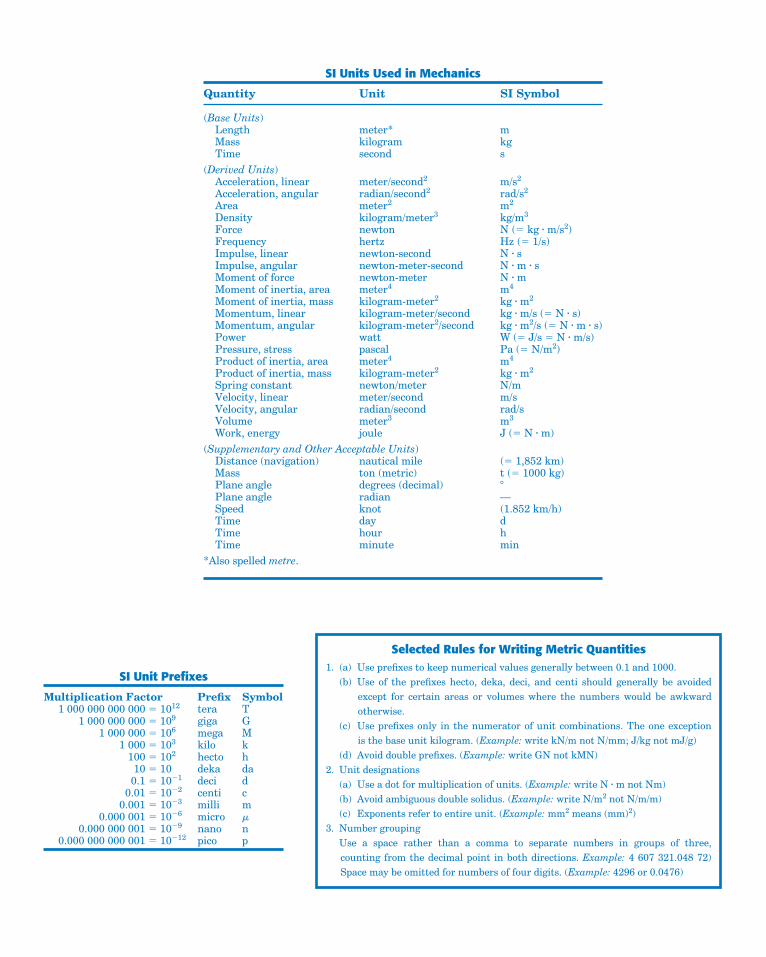
SI Units Used in Mechanics
Quantity Unit SI Symbol
(Base Units)Length meter* mMass kilogram kgTime second s
(Derived Units)Acceleration, linear meter/second2 m/s2
Acceleration, angular radian/second2 rad/s2
Area meter2 m2
Density kilogram/meter3 kg/m3
Force newton N (� kg � m/s2)Frequency hertz Hz (� 1/s)Impulse, linear newton-second N � sImpulse, angular newton-meter-second N � m � sMoment of force newton-meter N � mMoment of inertia, area meter4 m4
Moment of inertia, mass kilogram-meter2 kg � m2
Momentum, linear kilogram-meter/second kg � m/s (� N � s)Momentum, angular kilogram-meter2/second kg � m2/s (� N � m � s)Power watt W (� J/s � N � m/s)Pressure, stress pascal Pa (� N/m2)Product of inertia, area meter4 m4
Product of inertia, mass kilogram-meter2 kg � m2
Spring constant newton/meter N/mVelocity, linear meter/second m/sVelocity, angular radian/second rad/sVolume meter3 m3
Work, energy joule J (� N � m)(Supplementary and Other Acceptable Units)
Distance (navigation) nautical mile (� 1,852 km)Mass ton (metric) t (� 1000 kg)Plane angle degrees (decimal) �Plane angle radian —Speed knot (1.852 km/h)Time day dTime hour hTime minute min
*Also spelled metre.
SI Unit Prefixes
Multiplication Factor Prefix Symbol1 000 000 000 000 � 1012 tera T
1 000 000 000 � 109 giga G1 000 000 � 106 mega M
1 000 � 103 kilo k100 � 102 hecto h10 � 10 deka da
0.1 � 10�1 deci d0.01 � 10�2 centi c
0.001 � 10�3 milli m0.000 001 � 10�6 micro �
0.000 000 001 � 10�9 nano n0.000 000 000 001 � 10�12 pico p
Selected Rules for Writing Metric Quantities1. (a) Use prefixes to keep numerical values generally between 0.1 and 1000.
(b) Use of the prefixes hecto, deka, deci, and centi should generally be avoidedexcept for certain areas or volumes where the numbers would be awkwardotherwise.
(c) Use prefixes only in the numerator of unit combinations. The one exception is the base unit kilogram. (Example: write kN/m not N/mm; J/kg not mJ/g)
(d) Avoid double prefixes. (Example: write GN not kMN)2. Unit designations
(a) Use a dot for multiplication of units. (Example: write N � m not Nm)(b) Avoid ambiguous double solidus. (Example: write N/m2 not N/m/m)(c) Exponents refer to entire unit. (Example: mm2 means (mm)2)
3. Number groupingUse a space rather than a comma to separate numbers in groups of three,counting from the decimal point in both directions. Example: 4 607 321.048 72)Space may be omitted for numbers of four digits. (Example: 4296 or 0.0476)
xiv Chapter 5 Distributed Forces
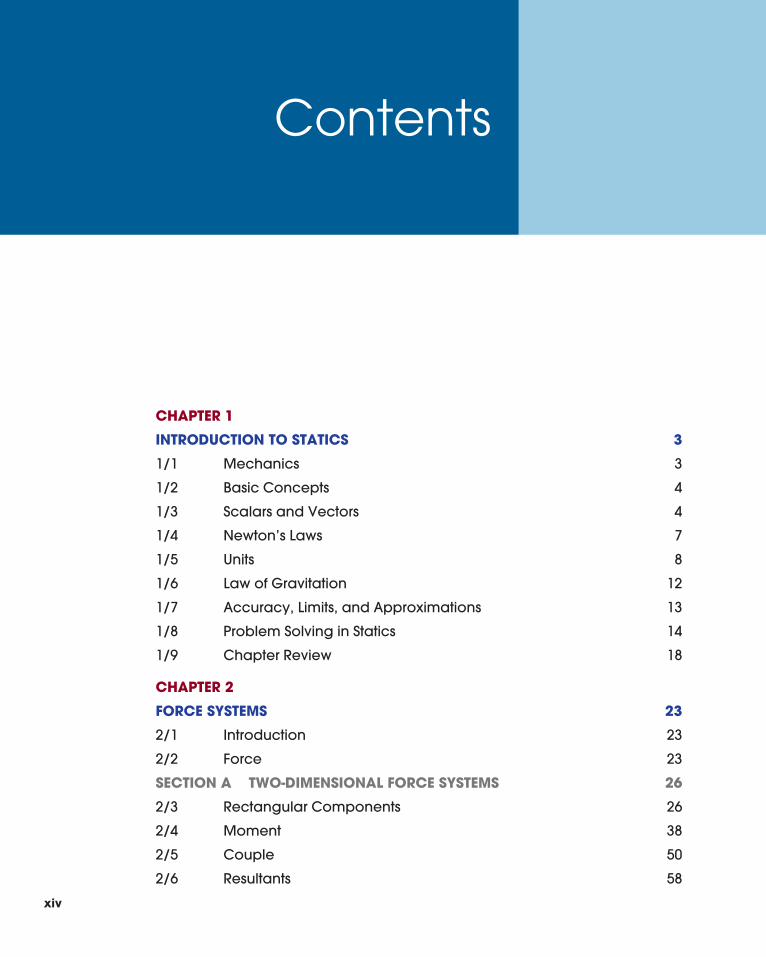
CHAPTER 1
INTRODUCTION TO STATICS 3
1/1 Mechanics 3
1/2 Basic Concepts 4
1/3 Scalars and Vectors 4
1/4 Newton’s Laws 7
1/5 Units 8
1/6 Law of Gravitation 12
1/7 Accuracy, Limits, and Approximations 13
1/8 Problem Solving in Statics 14
1/9 Chapter Review 18
CHAPTER 2
FORCE SYSTEMS 23
2/1 Introduction 23
2/2 Force 23
SECTION A TWO-DIMENSIONAL FORCE SYSTEMS 26
2/3 Rectangular Components 26
2/4 Moment 38
2/5 Couple 50
2/6 Resultants 58
Contents
xiv
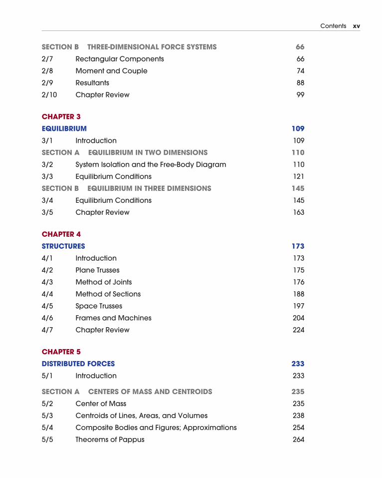
Contents xv
SECTION B THREE-DIMENSIONAL FORCE SYSTEMS 66
2/7 Rectangular Components 66
2/8 Moment and Couple 74
2/9 Resultants 88
2/10 Chapter Review 99
CHAPTER 3
EQUILIBRIUM 109
3/1 Introduction 109
SECTION A EQUILIBRIUM IN TWO DIMENSIONS 110
3/2 System Isolation and the Free-Body Diagram 110
3/3 Equilibrium Conditions 121
SECTION B EQUILIBRIUM IN THREE DIMENSIONS 145
3/4 Equilibrium Conditions 145
3/5 Chapter Review 163
CHAPTER 4
STRUCTURES 173
4/1 Introduction 173
4/2 Plane Trusses 175
4/3 Method of Joints 176
4/4 Method of Sections 188
4/5 Space Trusses 197
4/6 Frames and Machines 204
4/7 Chapter Review 224
CHAPTER 5
DISTRIBUTED FORCES 233
5/1 Introduction 233
SECTION A CENTERS OF MASS AND CENTROIDS 235
5/2 Center of Mass 235
5/3 Centroids of Lines, Areas, and Volumes 238
5/4 Composite Bodies and Figures; Approximations 254
5/5 Theorems of Pappus 264
SECTION B SPECIAL TOPICS 272
5/6 Beams—External Effects 272
5/7 Beams—Internal Effects 279
5/8 Flexible Cables 291
5/9 Fluid Statics 306
5/10 Chapter Review 325
CHAPTER 6
FRICTION 335
6/1 Introduction 335
SECTION A FRICTIONAL PHENOMENA 336
6/2 Types of Friction 336
6/3 Dry Friction 337
SECTION B APPLICATIONS OF FRICTION IN MACHINES 357
6/4 Wedges 357
6/5 Screws 358
6/6 Journal Bearings 368
6/7 Thrust Bearings; Disk Friction 369
6/8 Flexible Belts 377
6/9 Rolling Resistance 378
6/10 Chapter Review 387
CHAPTER 7
VIRTUAL WORK 397
7/1 Introduction 397
7/2 Work 397
7/3 Equilibrium 401
7/4 Potential Energy and Stability 417
7/5 Chapter Review 433
APPENDICES
APPENDIX A AREA MOMENTS OF INERTIA 441
A/1 Introduction 441
A/2 Definitions 442
xvi Contents
A/3 Composite Areas 456
A/4 Products of Inertia and Rotation of Axes 464
APPENDIX B MASS MOMENTS OF INERTIA 477
APPENDIX C SELECTED TOPICS OF MATHEMATICS 479
C/1 Introduction 479
C/2 Plane Geometry 479
C/3 Solid Geometry 480
C/4 Algebra 480
C/5 Analytic Geometry 481
C/6 Trigonometry 481
C/7 Vector Operations 482
C/8 Series 485
C/9 Derivatives 485
C/10 Integrals 486
C/11 Newton’s Method for Solving Intractable Equations 489
C/12 Selected Techniques for Numerical Integration 491
APPENDIX D USEFUL TABLES 495
Table D/1 Physical Properties 495
Table D/2 Solar System Constants 496
Table D/3 Properties of Plane Figures 497
Table D/4 Properties of Homogeneous Solids 499
INDEX 503
PROBLEM ANSWERS 507
Contents xvii
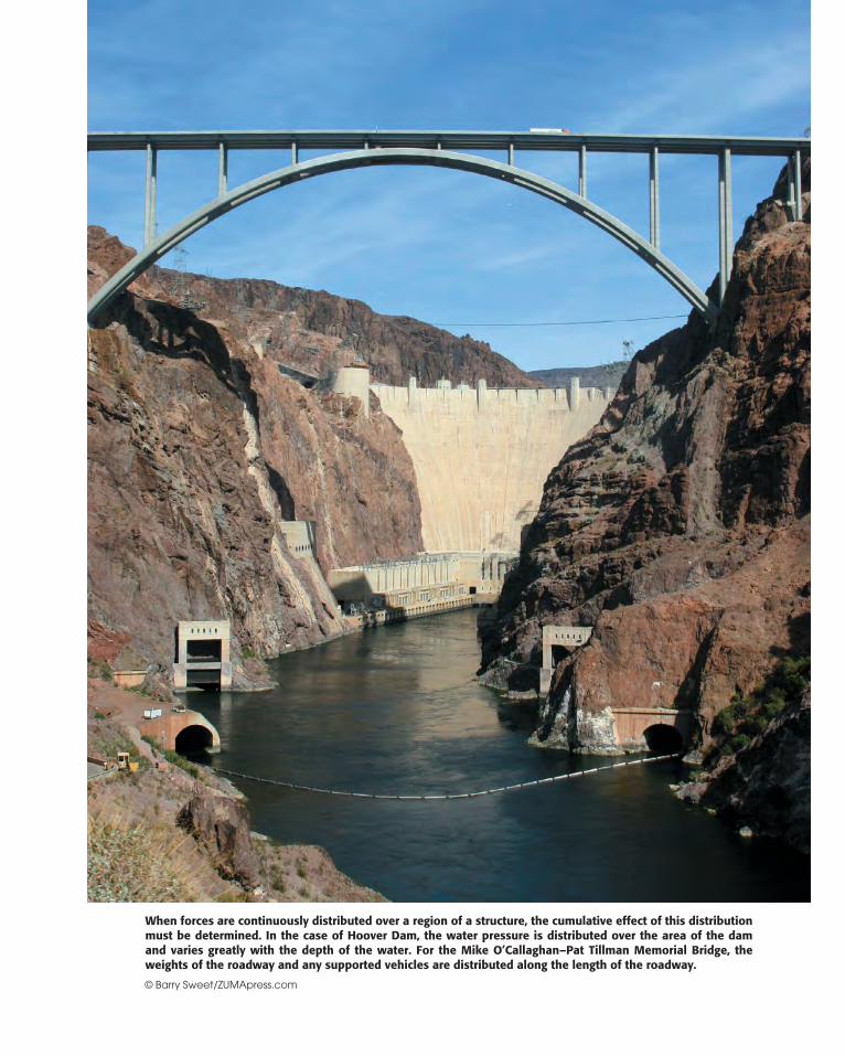
When forces are continuously distributed over a region of a structure, the cumulative effect of this distributionmust be determined. In the case of Hoover Dam, the water pressure is distributed over the area of the damand varies greatly with the depth of the water. For the Mike O’Callaghan–Pat Tillman Memorial Bridge, theweights of the roadway and any supported vehicles are distributed along the length of the roadway.
© Barry Sweet/ZUMApress.com

233
5/1 Introduction
Section A Centers of Mass and Centroids
5/2 Center of Mass
5/3 Centroids of Lines, Areas, and Volumes
5/4 Composite Bodies and Figures; Approximations
5/5 Theorems of Pappus
Section B Special Topics
5/6 Beams—External Effects
5/7 Beams—Internal Effects
5/8 Flexible Cables
5/9 Fluid Statics
5/10 Chapter Review
CHAPTER OUTLINE
55/1 Introduction
In the previous chapters we treated all forces as concentrated alongtheir lines of action and at their points of application. This treatmentprovided a reasonable model for those forces. Actually, “concentrated”forces do not exist in the exact sense, since every external force appliedmechanically to a body is distributed over a finite contact area, howeversmall.
The force exerted by the pavement on an automobile tire, for in-stance, is applied to the tire over its entire area of contact, Fig. 5/1a,which may be appreciable if the tire is soft. When analyzing the forcesacting on the car as a whole, if the dimension b of the contact area isnegligible compared with the other pertinent dimensions, such as thedistance between wheels, then we may replace the actual distributedcontact forces by their resultant R treated as a concentrated force. Eventhe force of contact between a hardened steel ball and its race in aloaded ball bearing, Fig. 5/1b, is applied over a finite though extremelysmall contact area. The forces applied to a two-force member of a truss,Fig. 5/1c, are applied over an actual area of contact of the pin againstthe hole and internally across the cut section as shown. In these andother similar examples we may treat the forces as concentrated whenanalyzing their external effects on bodies as a whole.
DistributedForces
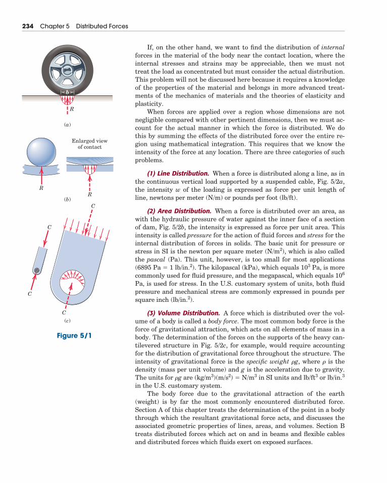
If, on the other hand, we want to find the distribution of internalforces in the material of the body near the contact location, where theinternal stresses and strains may be appreciable, then we must nottreat the load as concentrated but must consider the actual distribution.This problem will not be discussed here because it requires a knowledgeof the properties of the material and belongs in more advanced treat-ments of the mechanics of materials and the theories of elasticity andplasticity.
When forces are applied over a region whose dimensions are notnegligible compared with other pertinent dimensions, then we must ac-count for the actual manner in which the force is distributed. We dothis by summing the effects of the distributed force over the entire re-gion using mathematical integration. This requires that we know theintensity of the force at any location. There are three categories of suchproblems.
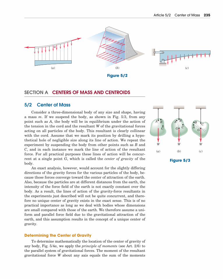
(1) Line Distribution. When a force is distributed along a line, as inthe continuous vertical load supported by a suspended cable, Fig. 5/2a,the intensity w of the loading is expressed as force per unit length ofline, newtons per meter (N/m) or pounds per foot (lb/ft).
(2) Area Distribution. When a force is distributed over an area, aswith the hydraulic pressure of water against the inner face of a sectionof dam, Fig. 5/2b, the intensity is expressed as force per unit area. Thisintensity is called pressure for the action of fluid forces and stress for theinternal distribution of forces in solids. The basic unit for pressure orstress in SI is the newton per square meter (N/m2), which is also calledthe pascal (Pa). This unit, however, is too small for most applications(6895 Pa � 1 lb/in.2). The kilopascal (kPa), which equals 103 Pa, is morecommonly used for fluid pressure, and the megapascal, which equals 106
Pa, is used for stress. In the U.S. customary system of units, both fluidpressure and mechanical stress are commonly expressed in pounds persquare inch (lb/in.2).
(3) Volume Distribution. A force which is distributed over the vol-ume of a body is called a body force. The most common body force is theforce of gravitational attraction, which acts on all elements of mass in abody. The determination of the forces on the supports of the heavy can-tilevered structure in Fig. 5/2c, for example, would require accountingfor the distribution of gravitational force throughout the structure. Theintensity of gravitational force is the specific weight �g, where � is thedensity (mass per unit volume) and g is the acceleration due to gravity.The units for �g are (kg/m3)(m/s2) � N/m3 in SI units and lb/ft3 or lb/in.3
in the U.S. customary system.The body force due to the gravitational attraction of the earth
(weight) is by far the most commonly encountered distributed force.Section A of this chapter treats the determination of the point in a bodythrough which the resultant gravitational force acts, and discusses theassociated geometric properties of lines, areas, and volumes. Section Btreats distributed forces which act on and in beams and flexible cablesand distributed forces which fluids exert on exposed surfaces.
234 Chapter 5 Distributed Forces
b
R
(a)
(b)
(b)
(c)
Enlarged viewof contact
R
C
C
C
C
R
Figure 5/1
SECTION A CENTERS OF MASS AND CENTROIDS
5/2 Center of MassConsider a three-dimensional body of any size and shape, having
a mass m. If we suspend the body, as shown in Fig. 5/3, from anypoint such as A, the body will be in equilibrium under the action ofthe tension in the cord and the resultant W of the gravitational forcesacting on all particles of the body. This resultant is clearly collinearwith the cord. Assume that we mark its position by drilling a hypo-thetical hole of negligible size along its line of action. We repeat theexperiment by suspending the body from other points such as B andC, and in each instance we mark the line of action of the resultantforce. For all practical purposes these lines of action will be concur-rent at a single point G, which is called the center of gravity of thebody.
An exact analysis, however, would account for the slightly differingdirections of the gravity forces for the various particles of the body, be-cause those forces converge toward the center of attraction of the earth.Also, because the particles are at different distances from the earth, theintensity of the force field of the earth is not exactly constant over thebody. As a result, the lines of action of the gravity-force resultants in the experiments just described will not be quite concurrent, and there-fore no unique center of gravity exists in the exact sense. This is of nopractical importance as long as we deal with bodies whose dimensionsare small compared with those of the earth. We therefore assume a uni-form and parallel force field due to the gravitational attraction of theearth, and this assumption results in the concept of a unique center ofgravity.
Determining the Center of GravityTo determine mathematically the location of the center of gravity of
any body, Fig. 5/4a, we apply the principle of moments (see Art. 2/6) tothe parallel system of gravitational forces. The moment of the resultantgravitational force W about any axis equals the sum of the moments
Article 5/2 Center of Mass 235
w
(a) (c)(b)
Figure 5/2
A B A
A
B BC
GC CG
W
(a) (b) (c)
W W
Figure 5/3
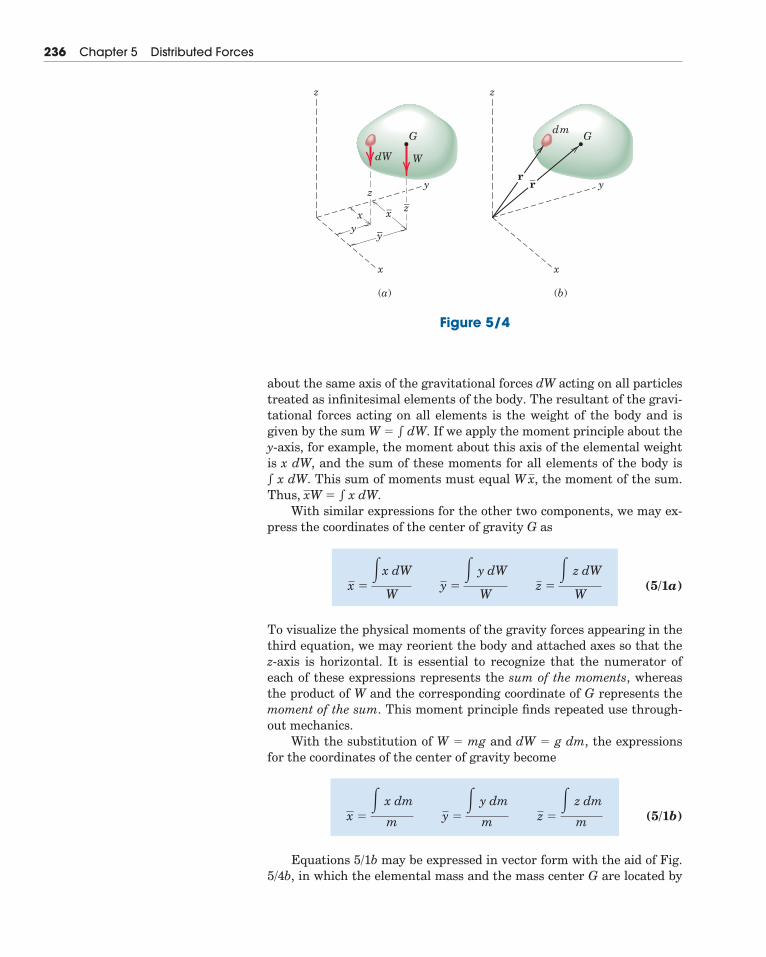
about the same axis of the gravitational forces dW acting on all particlestreated as infinitesimal elements of the body. The resultant of the gravi-tational forces acting on all elements is the weight of the body and isgiven by the sum W � dW. If we apply the moment principle about they-axis, for example, the moment about this axis of the elemental weightis x dW, and the sum of these moments for all elements of the body is x dW. This sum of moments must equal the moment of the sum.Thus, � x dW.
With similar expressions for the other two components, we may ex-press the coordinates of the center of gravity G as
(5/1a)
To visualize the physical moments of the gravity forces appearing in thethird equation, we may reorient the body and attached axes so that thez-axis is horizontal. It is essential to recognize that the numerator ofeach of these expressions represents the sum of the moments, whereasthe product of W and the corresponding coordinate of G represents themoment of the sum. This moment principle finds repeated use through-out mechanics.
With the substitution of W � mg and dW � g dm, the expressionsfor the coordinates of the center of gravity become
(5/1b)
Equations 5/1b may be expressed in vector form with the aid of Fig.5/4b, in which the elemental mass and the mass center G are located by
x �� x dm
m y �� y dm
m z �� z dm
m
x ��x dW
W y �
� y dW
W z �
� z dW
W
xWW x,
236 Chapter 5 Distributed Forces
x x
yy
z
zz_
z
dW
dm
W
G G
xy
y_
x_
rr_
(a) (b)
Figure 5/4
their respective position vectors r � xi � yj � zk and �
Thus, Eqs. 5/1b are the components of the single vector equation
(5/2)
The density � of a body is its mass per unit volume. Thus, the massof a differential element of volume dV becomes dm � � dV. If � is notconstant throughout the body but can be expressed as a function of thecoordinates of the body, we must account for this variation when calcu-lating the numerators and denominators of Eqs. 5/1b. We may thenwrite these expressions as
(5/3)
Center of Mass versus Center of GravityEquations 5/1b, 5/2, and 5/3 are independent of gravitational effects
since g no longer appears. They therefore define a unique point in thebody which is a function solely of the distribution of mass. This point iscalled the center of mass, and clearly it coincides with the center of grav-ity as long as the gravity field is treated as uniform and parallel.
It is meaningless to speak of the center of gravity of a body which isremoved from the gravitational field of the earth, since no gravitationalforces would act on it. The body would, however, still have its uniquecenter of mass. We will usually refer henceforth to the center of massrather than to the center of gravity. Also, the center of mass has a spe-cial significance in calculating the dynamic response of a body to unbal-anced forces. This class of problems is discussed at length in Vol. 2Dynamics.
In most problems the calculation of the position of the center ofmass may be simplified by an intelligent choice of reference axes. In gen-eral the axes should be placed so as to simplify the equations of theboundaries as much as possible. Thus, polar coordinates will be usefulfor bodies with circular boundaries.
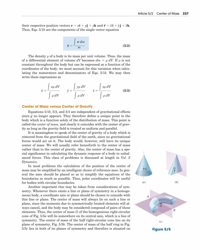
Another important clue may be taken from considerations of sym-metry. Whenever there exists a line or plane of symmetry in a homoge-neous body, a coordinate axis or plane should be chosen to coincide withthis line or plane. The center of mass will always lie on such a line orplane, since the moments due to symmetrically located elements will al-ways cancel, and the body may be considered composed of pairs of theseelements. Thus, the center of mass G of the homogeneous right-circularcone of Fig. 5/5a will lie somewhere on its central axis, which is a line ofsymmetry. The center of mass of the half right-circular cone lies on itsplane of symmetry, Fig. 5/5b. The center of mass of the half ring in Fig.5/5c lies in both of its planes of symmetry and therefore is situated on
x �� x� dV
� � dV y �
� y� dV
� � dV z �
� z� dV
� � dV
r �� r dm
m
xi � y j � z k.r
Article 5/2 Center of Mass 237
G
(a) (b)
(c)
G
A
B
G
Figure 5/5
line AB. It is easiest to find the location of G by using symmetry when itexists.
5/3 Centroids of Lines, Areas, and VolumesWhen the density � of a body is uniform throughout, it will be a
constant factor in both the numerators and denominators of Eqs. 5/3and will therefore cancel. The remaining expressions define a purelygeometrical property of the body, since any reference to its mass prop-erties has disappeared. The term centroid is used when the calculationconcerns a geometrical shape only. When speaking of an actual physicalbody, we use the term center of mass. If the density is uniform through-out the body, the positions of the centroid and center of mass are iden-tical, whereas if the density varies, these two points will, in general, notcoincide.
The calculation of centroids falls within three distinct categories,depending on whether we can model the shape of the body involved as aline, an area, or a volume.
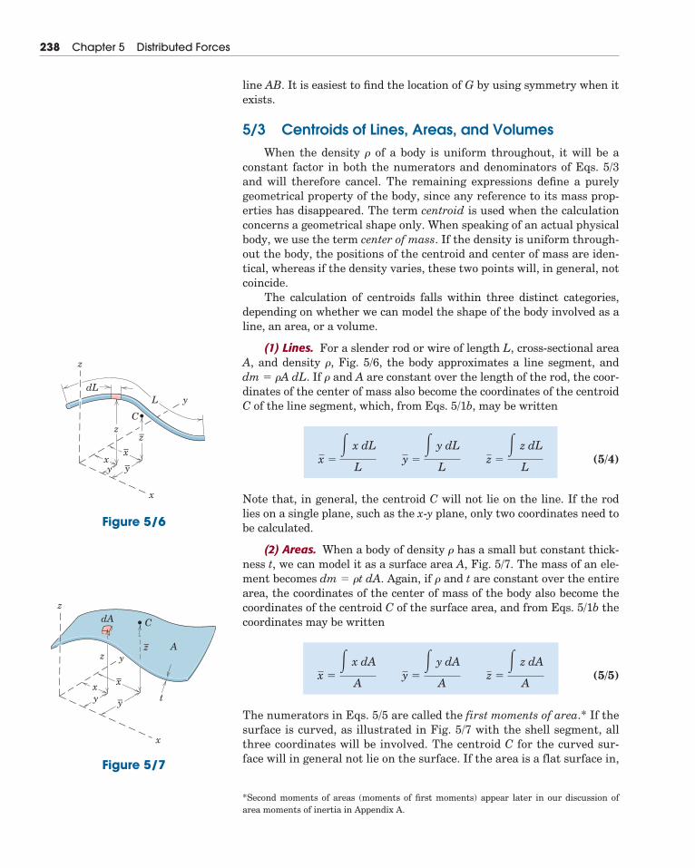
(1) Lines. For a slender rod or wire of length L, cross-sectional areaA, and density �, Fig. 5/6, the body approximates a line segment, and dm � �A dL. If � and A are constant over the length of the rod, the coor-dinates of the center of mass also become the coordinates of the centroidC of the line segment, which, from Eqs. 5/1b, may be written
(5/4)
Note that, in general, the centroid C will not lie on the line. If the rodlies on a single plane, such as the x-y plane, only two coordinates need tobe calculated.
(2) Areas. When a body of density � has a small but constant thick-ness t, we can model it as a surface area A, Fig. 5/7. The mass of an ele-ment becomes dm � �t dA. Again, if � and t are constant over the entirearea, the coordinates of the center of mass of the body also become thecoordinates of the centroid C of the surface area, and from Eqs. 5/1b thecoordinates may be written
(5/5)
The numerators in Eqs. 5/5 are called the first moments of area.* If thesurface is curved, as illustrated in Fig. 5/7 with the shell segment, allthree coordinates will be involved. The centroid C for the curved sur-face will in general not lie on the surface. If the area is a flat surface in,
x �� x dA
A y �
� y dA
A z �
� z dA
A
x �� x dL
L y �
� y dL
L z �
� z dL
L
238 Chapter 5 Distributed Forces
*Second moments of areas (moments of first moments) appear later in our discussion ofarea moments of inertia in Appendix A.
z
z
y
C
x
dL
x–
y–
z–
yx
L
Figure 5/6
z
z y
C
A
x
dA
x–
y–
z–
yx
t
Figure 5/7
say, the x-y plane, only the coordinates of C in that plane need to becalculated.
(3) Volumes. For a general body of volume V and density �, the ele-ment has a mass dm � � dV. The density � cancels if it is constant overthe entire volume, and the coordinates of the center of mass also becomethe coordinates of the centroid C of the body. From Eqs. 5/3 or 5/1b theybecome
(5/6)x �� x dV
V y �
� y dV
V z �
� z dV
V
Article 5/3 Centroids of Lines, Areas, and Volumes 239
y
y
z
x
x
y
x
(a)
(b)
dy
l
dy
dydx
y
r
Figure 5/8
KEY CONCEPTS
y
xx1
Figure 5/9
y
xdx
dy
y
Figure 5/10
Choice of Element for IntegrationThe principal difficulty with a theory often lies not in its concepts
but in the procedures for applying it. With mass centers and centroidsthe concept of the moment principle is simple enough; the difficult stepsare the choice of the differential element and setting up the integrals.The following five guidelines will be useful.
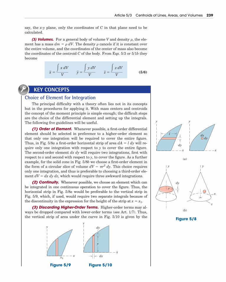
(1) Order of Element. Whenever possible, a first-order differentialelement should be selected in preference to a higher-order element sothat only one integration will be required to cover the entire figure.Thus, in Fig. 5/8a a first-order horizontal strip of area dA � l dy will re-quire only one integration with respect to y to cover the entire figure.The second-order element dx dy will require two integrations, first withrespect to x and second with respect to y, to cover the figure. As a furtherexample, for the solid cone in Fig. 5/8b we choose a first-order element inthe form of a circular slice of volume dV � �r2 dy. This choice requiresonly one integration, and thus is preferable to choosing a third-order ele-ment dV � dx dy dz, which would require three awkward integrations.
(2) Continuity. Whenever possible, we choose an element which canbe integrated in one continuous operation to cover the figure. Thus, thehorizontal strip in Fig. 5/8a would be preferable to the vertical strip inFig. 5/9, which, if used, would require two separate integrals because ofthe discontinuity in the expression for the height of the strip at x � x1.
(3) Discarding Higher-Order Terms. Higher-order terms may al-ways be dropped compared with lower-order terms (see Art. 1/7). Thus,the vertical strip of area under the curve in Fig. 5/10 is given by the
first-order term dA � y dx, and the second-order triangular area is discarded. In the limit, of course, there is no error.
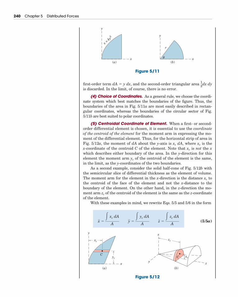
(4) Choice of Coordinates. As a general rule, we choose the coordi-nate system which best matches the boundaries of the figure. Thus, theboundaries of the area in Fig. 5/11a are most easily described in rectan-gular coordinates, whereas the boundaries of the circular sector of Fig.5/11b are best suited to polar coordinates.
(5) Centroidal Coordinate of Element. When a first- or second-order differential element is chosen, it is essential to use the coordinateof the centroid of the element for the moment arm in expressing the mo-ment of the differential element. Thus, for the horizontal strip of area inFig. 5/12a, the moment of dA about the y-axis is xc dA, where xc is the x-coordinate of the centroid C of the element. Note that xc is not the xwhich describes either boundary of the area. In the y-direction for thiselement the moment arm yc of the centroid of the element is the same,in the limit, as the y-coordinates of the two boundaries.
As a second example, consider the solid half-cone of Fig. 5/12b withthe semicircular slice of differential thickness as the element of volume.The moment arm for the element in the x-direction is the distance xc tothe centroid of the face of the element and not the x-distance to theboundary of the element. On the other hand, in the z-direction the mo-ment arm zc of the centroid of the element is the same as the z-coordinateof the element.
With these examples in mind, we rewrite Eqs. 5/5 and 5/6 in the form
(5/5a)x �� xc dA
A y �
� yc dA
A z �
� zc dA
A
12dx dy
240 Chapter 5 Distributed Forces
y
x
x = ky
2
(a)
y
x(b)
r
θ
Figure 5/11
y
x
xc
xcyc
zc
(a) (b)z
x
y
CC
Figure 5/12
and
(5/6a)
It is essential to recognize that the subscript c serves as a reminder thatthe moment arms appearing in the numerators of the integral expres-sions for moments are always the coordinates of the centroids of theparticular elements chosen.
At this point you should be certain to understand clearly the princi-ple of moments, which was introduced in Art. 2/4. You should recognizethe physical meaning of this principle as it is applied to the system ofparallel weight forces depicted in Fig. 5/4a. Keep in mind the equiva-lence between the moment of the resultant weight W and the sum (inte-gral) of the moments of the elemental weights dW, to avoid mistakes insetting up the necessary mathematics. Recognition of the principle ofmoments will help in obtaining the correct expression for the momentarm xc, yc, or zc of the centroid of the chosen differential element.
Keeping in mind the physical picture of the principle of moments,we will recognize that Eqs. 5/4, 5/5, and 5/6, which are geometric rela-tionships, are descriptive also of homogeneous physical bodies, becausethe density � cancels. If the density of the body in question is not con-stant but varies throughout the body as some function of the coordi-nates, then it will not cancel from the numerator and denominator ofthe mass-center expressions. In this event, we must use Eqs. 5/3 as ex-plained earlier.
Sample Problems 5/1 through 5/5 which follow have been carefullychosen to illustrate the application of Eqs. 5/4, 5/5, and 5/6 for calculat-ing the location of the centroid for line segments (slender rods), areas(thin flat plates), and volumes (homogeneous solids). The five integra-tion considerations listed above are illustrated in detail in these sampleproblems.
Section C/10 of Appendix C contains a table of integrals which in-cludes those needed for the problems in this and subsequent chapters. Asummary of the centroidal coordinates for some of the commonly usedshapes is given in Tables D/3 and D/4, Appendix D.
x �� xc dV
V y �
� yc dV
V z �
� zc dV
V
Article 5/3 Centroids of Lines, Areas, and Volumes 241
SAMPLE PROBLEM 5/1
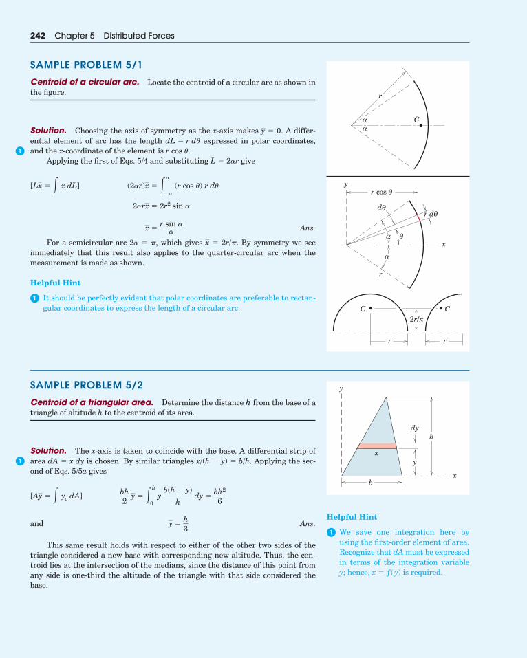
Centroid of a circular arc. Locate the centroid of a circular arc as shown inthe figure.
Solution. Choosing the axis of symmetry as the x-axis makes � 0. A differ-ential element of arc has the length expressed in polar coordinates,and the x-coordinate of the element is r cos �.
Applying the first of Eqs. 5/4 and substituting L � 2�r give
Ans.
For a semicircular arc 2� � �, which gives � 2r/�. By symmetry we seeimmediately that this result also applies to the quarter-circular arc when themeasurement is made as shown.
Helpful Hint
� It should be perfectly evident that polar coordinates are preferable to rectan-gular coordinates to express the length of a circular arc.
x
x �r sin �
�
2�rx � 2r2 sin �
(2�r)x � ��
�� (r cos �) r d�[Lx � � x dL]
dL � r d�
y
242 Chapter 5 Distributed Forces
r
αα
C
r
C C
x
yr cos θ
r dθdθ
α
α
θ
rr
2r/π
y
x
h
bx
y
dy
Helpful Hint
� We save one integration here byusing the first-order element of area.Recognize that dA must be expressedin terms of the integration variabley; hence, x � ƒ(y) is required.
SAMPLE PROBLEM 5/2
Centroid of a triangular area. Determine the distance from the base of atriangle of altitude h to the centroid of its area.
Solution. The x-axis is taken to coincide with the base. A differential strip ofarea dA � x dy is chosen. By similar triangles x/(h � y) � b/h. Applying the sec-ond of Eqs. 5/5a gives
and Ans.
This same result holds with respect to either of the other two sides of thetriangle considered a new base with corresponding new altitude. Thus, the cen-troid lies at the intersection of the medians, since the distance of this point fromany side is one-third the altitude of the triangle with that side considered thebase.
y �h3
bh2
y � �h
0y
b(h � y)
hdy �
bh2
6[Ay � � yc dA]
h
�
�
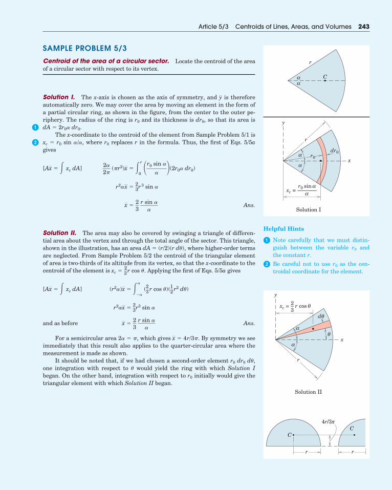
SAMPLE PROBLEM 5/3
Centroid of the area of a circular sector. Locate the centroid of the areaof a circular sector with respect to its vertex.
Solution I. The x-axis is chosen as the axis of symmetry, and is thereforeautomatically zero. We may cover the area by moving an element in the form ofa partial circular ring, as shown in the figure, from the center to the outer pe-riphery. The radius of the ring is r0 and its thickness is dr0, so that its area isdA � 2r0� dr0.
The x-coordinate to the centroid of the element from Sample Problem 5/1 isxc � r0 sin �/�, where r0 replaces r in the formula. Thus, the first of Eqs. 5/5agives
Ans.
Solution II. The area may also be covered by swinging a triangle of differen-tial area about the vertex and through the total angle of the sector. This triangle,shown in the illustration, has an area dA � (r/2)(r d�), where higher-order termsare neglected. From Sample Problem 5/2 the centroid of the triangular elementof area is two-thirds of its altitude from its vertex, so that the x-coordinate to thecentroid of the element is xc � cos �. Applying the first of Eqs. 5/5a gives
and as before Ans.
For a semicircular area 2� � �, which gives � 4r/3�. By symmetry we seeimmediately that this result also applies to the quarter-circular area where themeasurement is made as shown.
It should be noted that, if we had chosen a second-order element r0 dr0 d�,one integration with respect to � would yield the ring with which Solution Ibegan. On the other hand, integration with respect to r0 initially would give thetriangular element with which Solution II began.
x
x �23
r sin ��
r2�x �23r3 sin �
(r2�)x � ��
�� (23 r cos �)(12 r2 d�)[Ax � � xc dA]
23r
x �23
r sin ��
r2�x �23r3 sin �
2�2�
(�r2)x � � r
0�r0 sin �
� (2r0� dr0)[Ax � � xc dA]
y
Article 5/3 Centroids of Lines, Areas, and Volumes 243
C
r
αα
r
y
dr0
xr0α
α
αr0 sin
——–––α
xc =
Solution I
Helpful Hints
� Note carefully that we must distin-guish between the variable r0 andthe constant r.
� Be careful not to use r0 as the cen-troidal coordinate for the element.
x
r
y
αθ
dθ
α
CC
rr
π4r/3
xc = r cos θ2–3
Solution II
�
�
SAMPLE PROBLEM 5/4
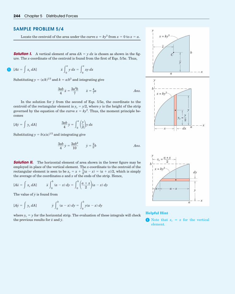
Locate the centroid of the area under the curve x � ky3 from x � 0 to x � a.
Solution I. A vertical element of area dA � y dx is chosen as shown in the fig-ure. The x-coordinate of the centroid is found from the first of Eqs. 5/5a. Thus,
Substituting y � (x/k)1/3 and k � a/b3 and integrating give
Ans.
In the solution for from the second of Eqs. 5/5a, the coordinate to the centroid of the rectangular element is where y is the height of the stripgoverned by the equation of the curve x � ky3. Thus, the moment principle be-comes
Substituting y � b(x/a)1/3 and integrating give
Ans.
Solution II. The horizontal element of area shown in the lower figure may beemployed in place of the vertical element. The x-coordinate to the centroid of therectangular element is seen to be xc � x � � (a � x)/2, which is simplythe average of the coordinates a and x of the ends of the strip. Hence,
The value of is found from
where yc � y for the horizontal strip. The evaluation of these integrals will checkthe previous results for and y.x
y �b
0 (a � x) dy � �b
0y(a � x) dy[Ay � � yc dA]
y
x �b
0 (a � x) dy � �b
0�a � x
2 (a � x) dy[Ax � � xc dA]
12(a � x)
3ab4
y �3ab2
10 y �
25b
3ab4
y � �a
0�y
2y dx[Ay � � yc dA]
yc � y/2,y
3ab4
x �3a2b
7 x �
47a
x �a
0y dx � �a
0xy dx[Ax � � xc dA]
244 Chapter 5 Distributed Forces
y
x = ky3
a
b
x
–x
–y
C
y
x = ky3
x a
y
b
xdx
yc =y–2
y
x = ky3
x
a
y
b
x
a – x
dy
xc =a + x––––
2
Helpful Hint
� Note that xc � x for the verticalelement.
�
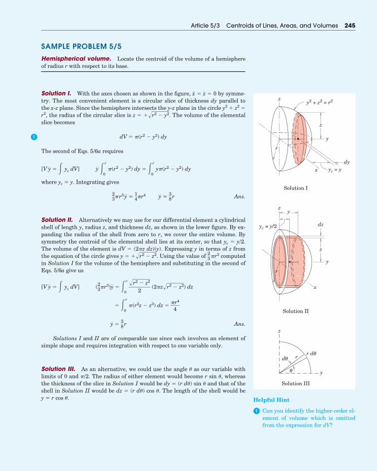
SAMPLE PROBLEM 5/5
Hemispherical volume. Locate the centroid of the volume of a hemisphereof radius r with respect to its base.
Solution I. With the axes chosen as shown in the figure, � � 0 by symme-try. The most convenient element is a circular slice of thickness dy parallel tothe x-z plane. Since the hemisphere intersects the y-z plane in the circle y2 � z2 �
r2, the radius of the circular slice is z � The volume of the elementalslice becomes
The second of Eqs. 5/6a requires
where yc � y. Integrating gives
Ans.
Solution II. Alternatively we may use for our differential element a cylindricalshell of length y, radius z, and thickness dz, as shown in the lower figure. By ex-panding the radius of the shell from zero to r, we cover the entire volume. Bysymmetry the centroid of the elemental shell lies at its center, so that yc � y/2.The volume of the element is dV � (2�z dz)(y). Expressing y in terms of z fromthe equation of the circle gives y � Using the value of computedin Solution I for the volume of the hemisphere and substituting in the second ofEqs. 5/6a give us
Ans.
Solutions I and II are of comparable use since each involves an element ofsimple shape and requires integration with respect to one variable only.
Solution III. As an alternative, we could use the angle � as our variable withlimits of 0 and �/2. The radius of either element would become r sin �, whereasthe thickness of the slice in Solution I would be dy � (r d�) sin � and that of theshell in Solution II would be dz � (r d�) cos �. The length of the shell would be y � r cos �.
y �38r
� � r
0�(r2z � z3) dz �
�r4
4
(23�r3)y � � r
0
�r2 � z2
2 (2�z�r2 � z2) dz[V y � � yc dV]
23 �r3��r2 � z2.
23�r3y �
14�r4 y �
38r
y � r
0�(r2 � y2) dy � � r
0y�(r2 � y2) dy[V y � � yc dV]
dV � �(r2 � y2) dy
��r2 � y2.
zx
Article 5/3 Centroids of Lines, Areas, and Volumes 245
z
y2 + z2 = r2
yc = y
y
xdy
dz
r
z
z
yc = y/2
y
y
r
y
z
r
x
r dθ
θ
dθ
Solution I
Solution II
Solution III
z
Helpful Hint
� Can you identify the higher-order el-ement of volume which is omittedfrom the expression for dV?
�
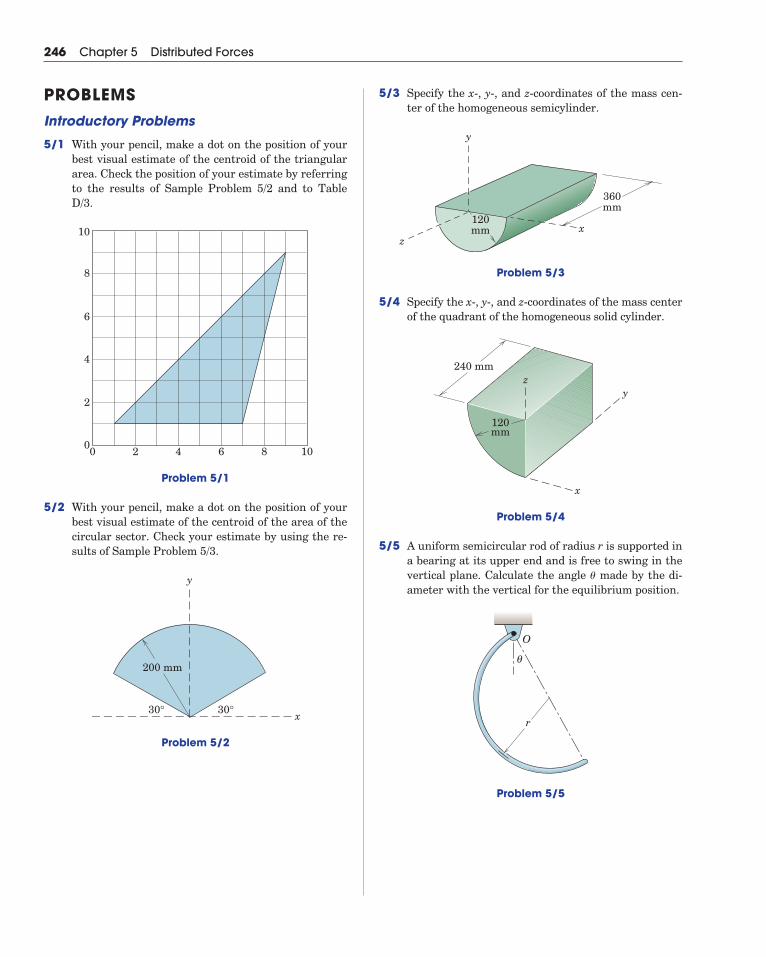
5/3 Specify the x-, y-, and z-coordinates of the mass cen-ter of the homogeneous semicylinder.
Problem 5/3
5/4 Specify the x-, y-, and z-coordinates of the mass centerof the quadrant of the homogeneous solid cylinder.
Problem 5/4
5/5 A uniform semicircular rod of radius r is supported ina bearing at its upper end and is free to swing in thevertical plane. Calculate the angle made by the di-ameter with the vertical for the equilibrium position.
Problem 5/5
r
θ
O
�
240 mmz
x
y
120mm
360mm
120mm
y
zx
246 Chapter 5 Distributed Forces
PROBLEMSIntroductory Problems
5/1 With your pencil, make a dot on the position of yourbest visual estimate of the centroid of the triangulararea. Check the position of your estimate by referringto the results of Sample Problem 5/2 and to TableD/3.
Problem 5/1
5/2 With your pencil, make a dot on the position of yourbest visual estimate of the centroid of the area of thecircular sector. Check your estimate by using the re-sults of Sample Problem 5/3.
Problem 5/2
y
30°30°
200 mm
x
0
2
4
6
8
10
0 2 4 6 8 10

5/6 Determine the y-coordinate of the centroid of the areaby direct integration.
Problem 5/6
5/7 Determine the y-coordinate of the centroid of theshaded area. Check your result for the special case
.
Problem 5/7
5/8 Determine the x- and y-coordinates of the centroid ofthe trapezoidal area.
Problem 5/8
xh
a
b
y
y
60°60°x
h
a
a � 0
R/2
y
x
R
Article 5/3 Problems 247
5/9 Determine the x- and y-coordinates of the centroid ofthe shaded area.
Problem 5/9
5/10 Determine the coordinates of the centroid of theshaded area.
Problem 5/10
5/11 Determine the coordinates of the centroid of theshaded area.
Problem 5/11
y
xa
b
y = b sinx—–
2aπ
y
a
b
x = ky2
x
x
y = 1 +x3—8
10
1
0 2
y
Representative Problems
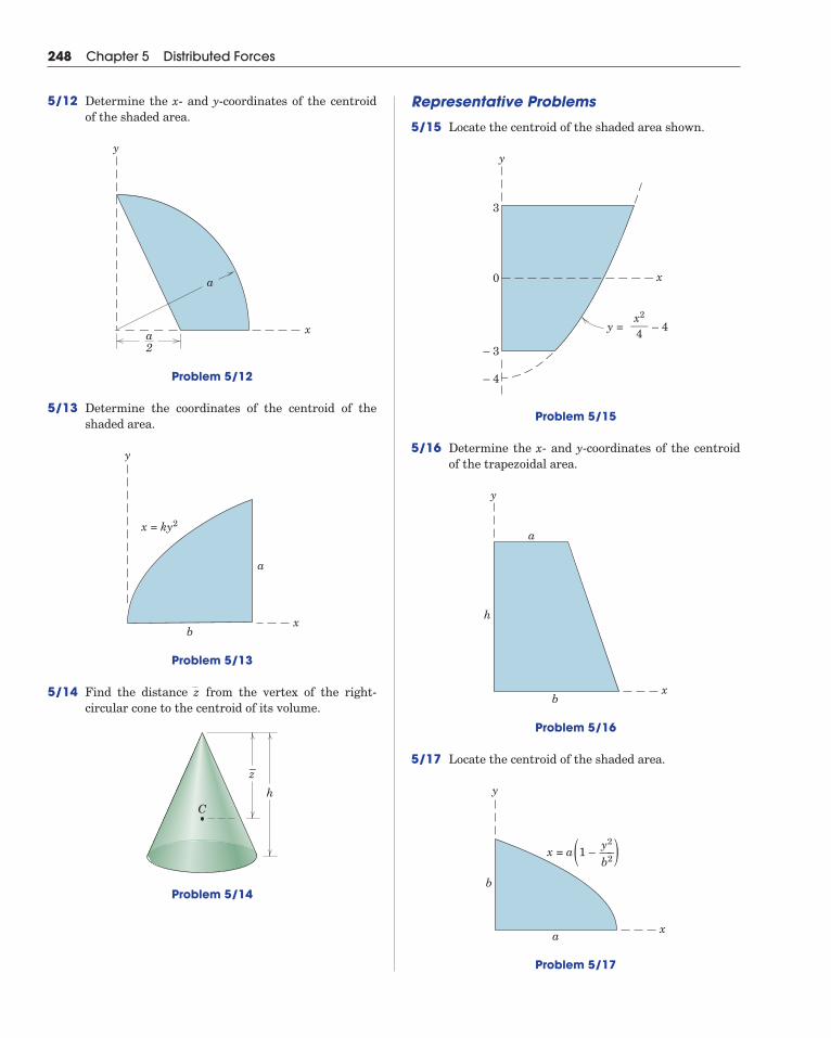
5/15 Locate the centroid of the shaded area shown.
Problem 5/15
5/16 Determine the x- and y-coordinates of the centroidof the trapezoidal area.
Problem 5/16
5/17 Locate the centroid of the shaded area.
Problem 5/17
xa
b
y
x = a 1 –( )y2—–b2
x
y
b
h
a
x
y
0
– 3
– 4
– 4y =
3
x2–––4
248 Chapter 5 Distributed Forces
5/12 Determine the x- and y-coordinates of the centroidof the shaded area.
Problem 5/12
5/13 Determine the coordinates of the centroid of theshaded area.
Problem 5/13
5/14 Find the distance from the vertex of the right-circular cone to the centroid of its volume.
Problem 5/14
Ch
z–
z
y
a
b
x = ky2
x
y
a2
x
a
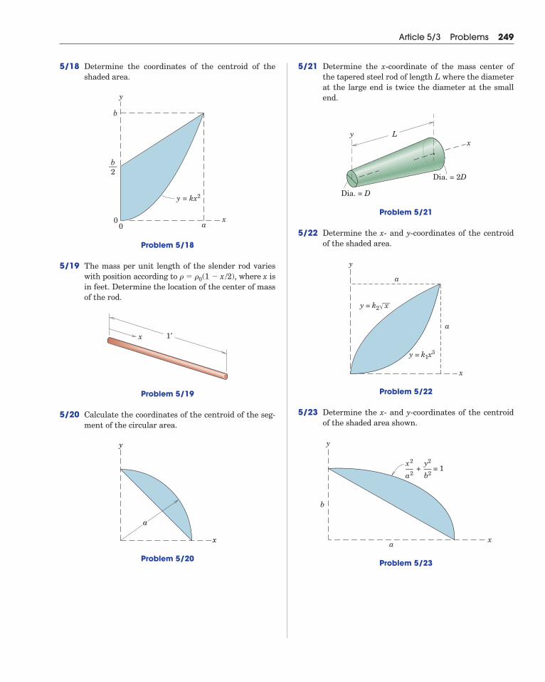
5/18 Determine the coordinates of the centroid of theshaded area.
Problem 5/18
5/19 The mass per unit length of the slender rod varieswith position according to , where x isin feet. Determine the location of the center of massof the rod.
Problem 5/19
5/20 Calculate the coordinates of the centroid of the seg-ment of the circular area.
Problem 5/20
y
x
a
x 1′
� � �0(1 � x/2)
0
b
0 a
y = kx2
x
y
b––2
Article 5/3 Problems 249
5/21 Determine the x-coordinate of the mass center ofthe tapered steel rod of length L where the diameterat the large end is twice the diameter at the smallend.
Problem 5/21
5/22 Determine the x- and y-coordinates of the centroidof the shaded area.
Problem 5/22
5/23 Determine the x- and y-coordinates of the centroidof the shaded area shown.
Problem 5/23
x
b
a
y
+ = 1x2—a2
y2—b2
y
x
a
a
y = k1x3
y = k2 x
xLy
Dia. = D
Dia. = 2D
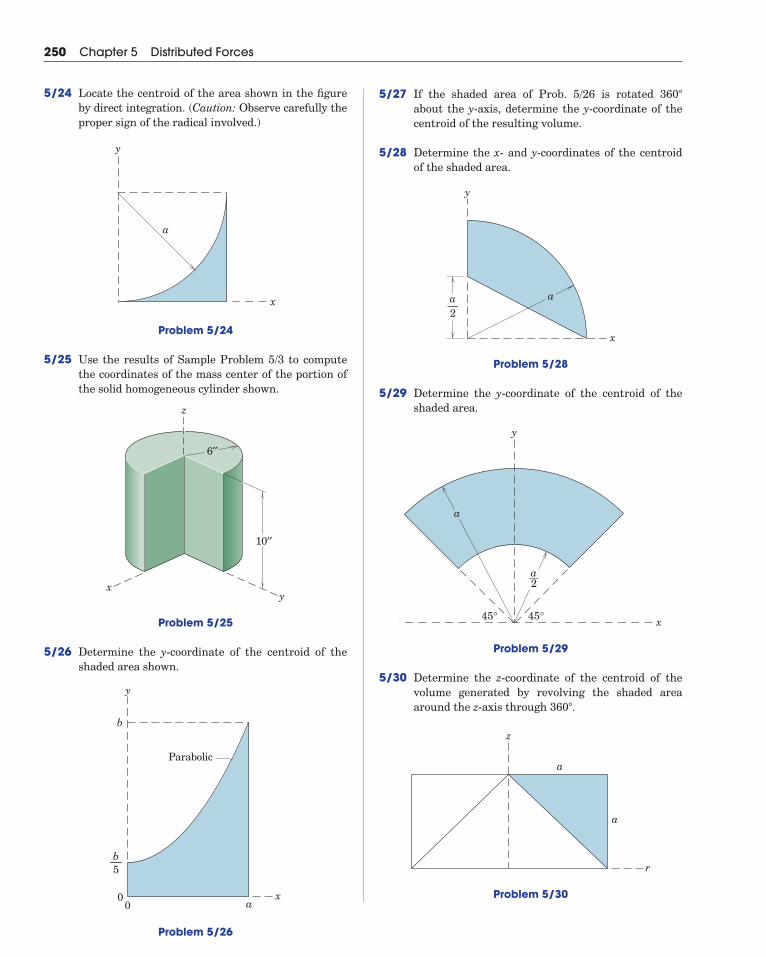
5/27 If the shaded area of Prob. 5/26 is rotated about the y-axis, determine the y-coordinate of thecentroid of the resulting volume.
5/28 Determine the x- and y-coordinates of the centroidof the shaded area.
Problem 5/28
5/29 Determine the y-coordinate of the centroid of theshaded area.
Problem 5/29
5/30 Determine the z-coordinate of the centroid of thevolume generated by revolving the shaded areaaround the z-axis through .
Problem 5/30
z
r
a
a
360�
y
x
a
a2
45°45°
x
y
a—2
a
360�
250 Chapter 5 Distributed Forces
5/24 Locate the centroid of the area shown in the figureby direct integration. (Caution: Observe carefully theproper sign of the radical involved.)
Problem 5/24
5/25 Use the results of Sample Problem 5/3 to computethe coordinates of the mass center of the portion ofthe solid homogeneous cylinder shown.
Problem 5/25
5/26 Determine the y-coordinate of the centroid of theshaded area shown.
Problem 5/26
0
b
0 ax
y
b––5
Parabolic
10′′
z
xy
6′′
y
x
a
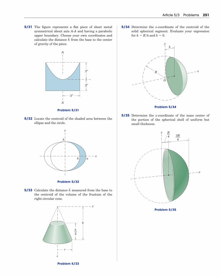
5/31 The figure represents a flat piece of sheet metalsymmetrical about axis A-A and having a parabolicupper boundary. Choose your own coordinates andcalculate the distance from the base to the centerof gravity of the piece.
Problem 5/31
5/32 Locate the centroid of the shaded area between theellipse and the circle.
Problem 5/32
5/33 Calculate the distance measured from the base tothe centroid of the volume of the frustum of theright-circular cone.
Problem 5/33
h
r
z
y
h—2
h
y
b
b ax
A
A
3′′
2′′
3′′
h
Article 5/3 Problems 251
5/34 Determine the x-coordinate of the centroid of thesolid spherical segment. Evaluate your expressionfor and .
Problem 5/34
5/35 Determine the x-coordinate of the mass center ofthe portion of the spherical shell of uniform butsmall thickness.
Problem 5/35
y
x
R—4 3R–—
4
y
x
O
h
R
h � 0h � R/4
5/39 Determine the y-coordinate of the centroid of thevolume generated by revolving the shaded area ofthe right triangle about the z-axis through asshown in the figure.
Problem 5/39
5/40 Determine the z-coordinate of the mass center of thehomogeneous quarter-spherical shell, which has aradius r.
Problem 5/40
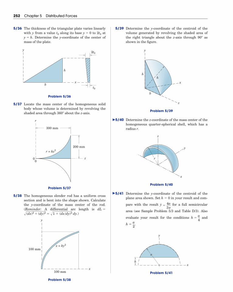
5/41 Determine the y-coordinate of the centroid of theplane area shown. Set in your result and com-
pare with the result for a full semicircular
area (see Sample Problem 5/3 and Table D/3). Also
evaluate your result for the conditions and
.
Problem 5/41
h
a
x
y
h �a2
h �a4
y �4a3�
h � 0
x
y
z
r
z
x
h
b
y
h
90�
252 Chapter 5 Distributed Forces
5/36 The thickness of the triangular plate varies linearlywith y from a value along its base to 2 at
. Determine the y-coordinate of the center ofmass of the plate.
Problem 5/36
5/37 Locate the mass center of the homogeneous solidbody whose volume is determined by revolving theshaded area through about the z-axis.
Problem 5/37
5/38 The homogeneous slender rod has a uniform crosssection and is bent into the shape shown. Calculatethe y-coordinate of the mass center of the rod. (Reminder: A differential arc length is
.)
Problem 5/38
100 mm
100 mm
y
x
x = ky2
�(dx)2 � (dy)2 � �1 � (dx/dy)2 dydL �
00 z
r
300 mm
200 mmr = kz3
360�
y
xb
h
t0
2t0
y � ht0y � 0t0
�
�
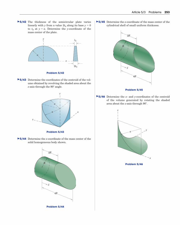
5/42 The thickness of the semicircular plate varies linearly with y from a value along its base to at Determine the y-coordinate of the mass center of the plate.
Problem 5/42
5/43 Determine the coordinates of the centroid of the vol-ume obtained by revolving the shaded area about thez-axis through the angle.
Problem 5/43
5/44 Determine the x-coordinate of the mass center of thesolid homogeneous body shown.
Problem 5/44
4R
2R
x
R
z
a
a x
y
90�
y
x
a
t0
2t0
y � a.t0
y � 02t0
Article 5/3 Problems 253
5/45 Determine the x-coordinate of the mass center of thecylindrical shell of small uniform thickness.
Problem 5/45
5/46 Determine the x- and y-coordinates of the centroidof the volume generated by rotating the shadedarea about the z-axis through .
Problem 5/46
z
ya
x
90�
4R
2R
x
R
�
�
�
�
�
5/4 Composite Bodies and Figures; Approximations
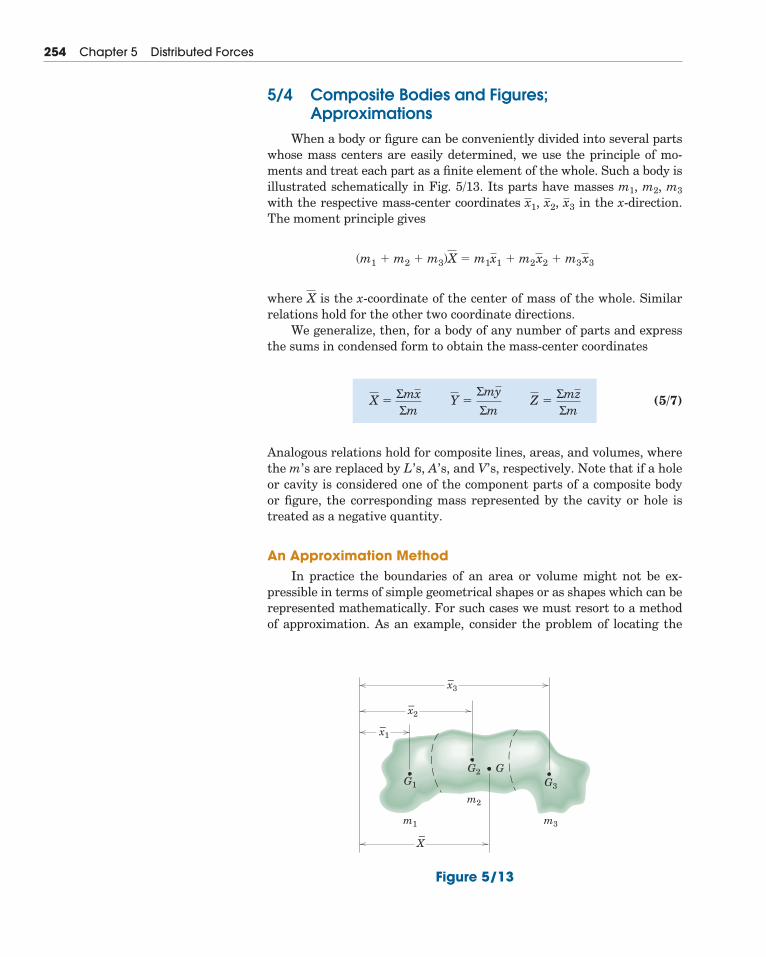
When a body or figure can be conveniently divided into several partswhose mass centers are easily determined, we use the principle of mo-ments and treat each part as a finite element of the whole. Such a body isillustrated schematically in Fig. 5/13. Its parts have masses m1, m2, m3
with the respective mass-center coordinates in the x-direction.The moment principle gives
where is the x-coordinate of the center of mass of the whole. Similarrelations hold for the other two coordinate directions.
We generalize, then, for a body of any number of parts and expressthe sums in condensed form to obtain the mass-center coordinates
(5/7)
Analogous relations hold for composite lines, areas, and volumes, wherethe m’s are replaced by L’s, A’s, and V’s, respectively. Note that if a holeor cavity is considered one of the component parts of a composite bodyor figure, the corresponding mass represented by the cavity or hole istreated as a negative quantity.
An Approximation MethodIn practice the boundaries of an area or volume might not be ex-
pressible in terms of simple geometrical shapes or as shapes which can berepresented mathematically. For such cases we must resort to a methodof approximation. As an example, consider the problem of locating the
X �ΣmxΣm
Y �ΣmyΣm
Z �ΣmzΣm
X
(m1 � m2 � m3)X � m1x1 � m2x2 � m3x3
x3x2,x1,
254 Chapter 5 Distributed Forces
– x3
– x2
–X
– x1
m1
m2
m3
G1
GG2G3
Figure 5/13
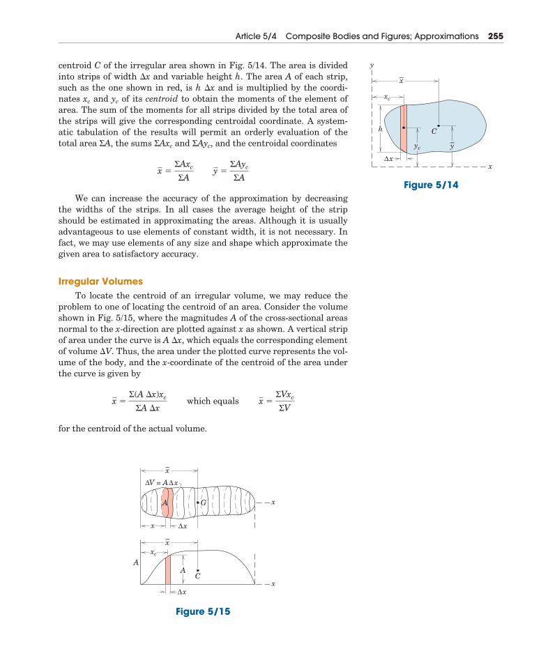
centroid C of the irregular area shown in Fig. 5/14. The area is dividedinto strips of width �x and variable height h. The area A of each strip,such as the one shown in red, is h �x and is multiplied by the coordi-nates xc and yc of its centroid to obtain the moments of the element ofarea. The sum of the moments for all strips divided by the total area ofthe strips will give the corresponding centroidal coordinate. A system-atic tabulation of the results will permit an orderly evaluation of thetotal area ΣA, the sums ΣAxc and ΣAyc, and the centroidal coordinates
We can increase the accuracy of the approximation by decreasingthe widths of the strips. In all cases the average height of the stripshould be estimated in approximating the areas. Although it is usuallyadvantageous to use elements of constant width, it is not necessary. Infact, we may use elements of any size and shape which approximate thegiven area to satisfactory accuracy.
Irregular VolumesTo locate the centroid of an irregular volume, we may reduce the
problem to one of locating the centroid of an area. Consider the volumeshown in Fig. 5/15, where the magnitudes A of the cross-sectional areasnormal to the x-direction are plotted against x as shown. A vertical stripof area under the curve is A �x, which equals the corresponding elementof volume �V. Thus, the area under the plotted curve represents the vol-ume of the body, and the x-coordinate of the centroid of the area underthe curve is given by
for the centroid of the actual volume.
x �Σ(A �x)xc
ΣA �x which equals x �
ΣVxc
ΣV
x �ΣAxc
ΣA y �
ΣAyc
ΣA
Article 5/4 Composite Bodies and Figures; Approximations 255
xc
yc
x
C
y
–x
–y
h
xΔ
Figure 5/14
–x
–x
A
x
G
C
x
xΔ
V = A xΔ Δ
xΔx
AA
xc
Figure 5/15
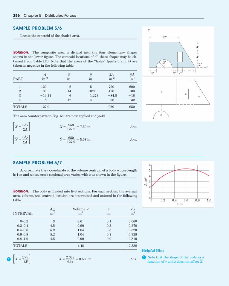
SAMPLE PROBLEM 5/6
Locate the centroid of the shaded area.
Solution. The composite area is divided into the four elementary shapesshown in the lower figure. The centroid locations of all these shapes may be ob-tained from Table D/3. Note that the areas of the “holes” (parts 3 and 4) aretaken as negative in the following table:
APART in.2 in. in. in.3 in.3
1 120 6 5 720 6002 30 14 10/3 420 1003 �14.14 6 1.273 �84.8 �184 �8 12 4 �96 �32
TOTALS 127.9 959 650
The area counterparts to Eqs. 5/7 are now applied and yield
Ans.
Ans.
SAMPLE PROBLEM 5/7
Approximate the x-coordinate of the volume centroid of a body whose lengthis 1 m and whose cross-sectional area varies with x as shown in the figure.
Solution. The body is divided into five sections. For each section, the averagearea, volume, and centroid location are determined and entered in the followingtable:
Aav Volume VINTERVAL m2 m3 m m4
0–0.2 3 0.6 0.1 0.0600.2–0.4 4.5 0.90 0.3 0.2700.4–0.6 5.2 1.04 0.5 0.5200.6–0.8 5.2 1.04 0.7 0.7280.8–1.0 4.5 0.90 0.9 0.810
TOTALS 4.48 2.388
Ans.X �2.3884.48
� 0.533 m�X �ΣV xΣV�
V xx
Y �650
127.9� 5.08 in.�Y �
ΣAy
ΣA�
X �959
127.9� 7.50 in.�X �
ΣAxΣA�
yAxAyx
256 Chapter 5 Distributed Forces
Helpful Hint
� Note that the shape of the body as afunction of y and z does not affect X.
�
x
y
12″
3″
3″ 2″ 2″
2″
5″
4″
4″
14
2
3
00
1
2
3
4
5
6
0.2 0.4x, m
A, m
2
0.6 0.8 1.0
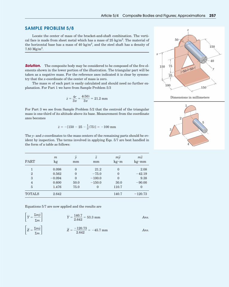
SAMPLE PROBLEM 5/8
Locate the center of mass of the bracket-and-shaft combination. The verti-cal face is made from sheet metal which has a mass of 25 kg/m2. The material ofthe horizontal base has a mass of 40 kg/m2, and the steel shaft has a density of7.83 Mg/m3.
Solution. The composite body may be considered to be composed of the five el-ements shown in the lower portion of the illustration. The triangular part will betaken as a negative mass. For the reference axes indicated it is clear by symme-try that the x-coordinate of the center of mass is zero.
The mass m of each part is easily calculated and should need no further ex-planation. For Part 1 we have from Sample Problem 5/3
For Part 3 we see from Sample Problem 5/2 that the centroid of the triangularmass is one-third of its altitude above its base. Measurement from the coordinateaxes becomes
The y- and z-coordinates to the mass centers of the remaining parts should be ev-ident by inspection. The terms involved in applying Eqs. 5/7 are best handled inthe form of a table as follows:
mPART kg mm mm
1 0.098 0 21.2 0 2.082 0.562 0 �75.0 0 �42.193 �0.094 0 �100.0 0 9.384 0.600 50.0 �150.0 30.0 �90.005 1.476 75.0 0 110.7 0
TOTALS 2.642 140.7 �120.73
Equations 5/7 are now applied and the results are
Ans.
Ans.Z ��120.73
2.642� �45.7 mm�Z �
ΣmzΣm�
Y �140.72.642
� 53.3 mm�Y �Σmy
Σm�
kg � mmkg � mmzmyzy
z � �[150 � 25 � 13(75)] � �100 mm
z �4r3�
�4(50)
3�� 21.2 mm
Article 5/4 Composite Bodies and Figures; Approximations 257
y
x
z
40
50 50
50
25
100
150 75
150
Dimensions in millimeters
150
1
2
3
4
5
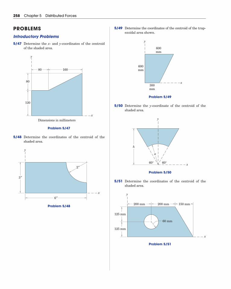
5/49 Determine the coordinates of the centroid of the trap-ezoidal area shown.
Problem 5/49
5/50 Determine the y-coordinate of the centroid of theshaded area.
Problem 5/50
5/51 Determine the coordinates of the centroid of theshaded area.
x
h
60°60°
a
y
x
600mm
600mm
300mm
y
258 Chapter 5 Distributed Forces
PROBLEMSIntroductory Problems
5/47 Determine the x- and y-coordinates of the centroidof the shaded area.
Problem 5/47
5/48 Determine the coordinates of the centroid of theshaded area.
Problem 5/48
3″
2″
6″
y
x
Dimensions in millimeters
80
80
120
160
y
x
x
125 mm
200 mm 200 mm
60 mm
150 mm
125 mm
y
Problem 5/51
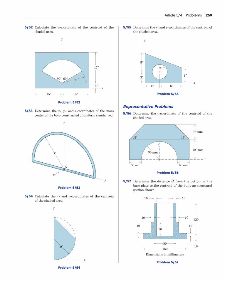
5/52 Calculate the y-coordinate of the centroid of theshaded area.
Problem 5/52
5/53 Determine the x-, y-, and z-coordinates of the masscenter of the body constructed of uniform slender rod.
Problem 5/53
5/54 Calculate the x- and y-coordinates of the centroid of the shaded area.
Problem 5/54
x
y
9"
z
y
x
O
r
60°
y
x
13″
17″
3″
15″ 15″
60°
Article 5/4 Problems 259
5/55 Determine the x- and y-coordinates of the centroid ofthe shaded area.
Problem 5/55
Representative Problems
5/56 Determine the y-coordinate of the centroid of theshaded area.
Problem 5/56
5/57 Determine the distance from the bottom of thebase plate to the centroid of the built-up structuralsection shown.
Problem 5/57
10 10
1010
10 10
1080
160
Dimensions in millimeters
120
50
H
x
60 mm
45° 45°
60 mm
75 mm
100 mm90 mm
y
y
x4′′
3′′
5′′
6′′
2′′
4′′
5/61 Determine the coordinates of the center of mass ofthe bracket, which is made from a plate of uniformthickness.
Problem 5/61
5/62 Determine the x-coordinate of the mass center ofthe homogeneous hemisphere with the smallerhemispherical portion removed.
Problem 5/62
y
x
z
R––2
R
80 mm
80 mm
40 mm
100 mm
z
y
x
260 Chapter 5 Distributed Forces
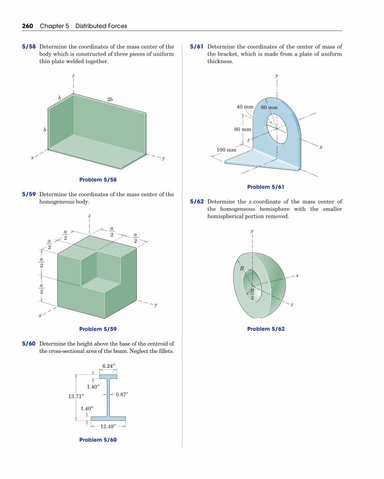
5/58 Determine the coordinates of the mass center of thebody which is constructed of three pieces of uniformthin plate welded together.
Problem 5/58
5/59 Determine the coordinates of the mass center of thehomogeneous body.
Problem 5/59
5/60 Determine the height above the base of the centroid ofthe cross-sectional area of the beam. Neglect the fillets.
Problem 5/60
6.24″
1.40″0.87″13.71″
1.40″
12.48″
z
y
x
a––2
a––2
a––2 a––
2a––2
a––2
b
b 2b
yx
z
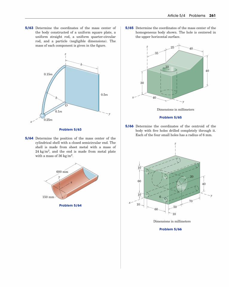
5/63 Determine the coordinates of the mass center of the body constructed of a uniform square plate, auniform straight rod, a uniform quarter-circularrod, and a particle (negligible dimensions). Themass of each component is given in the figure.
Problem 5/63
5/64 Determine the position of the mass center of thecylindrical shell with a closed semicircular end. Theshell is made from sheet metal with a mass of
, and the end is made from metal platewith a mass of .
Problem 5/64
150 mm
600 mm
y
x
36 kg /m224 kg /m2
b
0.5m
0.1m
0.25m
0.15m
y
x
z
O
b
Article 5/4 Problems 261
5/65 Determine the coordinates of the mass center of thehomogeneous body shown. The hole is centered inthe upper horizontal surface.
Problem 5/65
5/66 Determine the coordinates of the centroid of thebody with five holes drilled completely through it.Each of the four small holes has a radius of 6 mm.
Problem 5/66
x
z
y
Dimensions in millimeters
40
50
70
60
6
10
10
60
10
10
20
40
25 4035
Dimensions in millimeters
z
yx
30
40
10
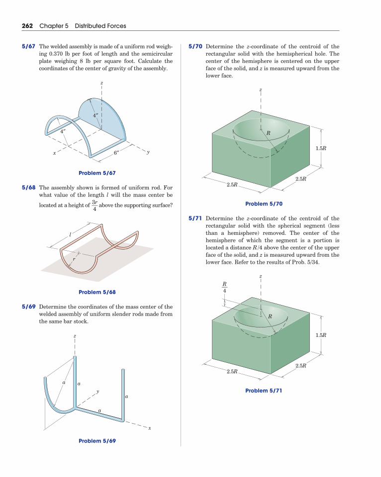
5/70 Determine the z-coordinate of the centroid of therectangular solid with the hemispherical hole. Thecenter of the hemisphere is centered on the upperface of the solid, and z is measured upward from thelower face.
Problem 5/70
5/71 Determine the z-coordinate of the centroid of therectangular solid with the spherical segment (lessthan a hemisphere) removed. The center of thehemisphere of which the segment is a portion is located a distance above the center of the upperface of the solid, and z is measured upward from thelower face. Refer to the results of Prob. 5/34.
Problem 5/71
z
1.5R
2.5R2.5R
R
R––4
R/4
z
1.5R
2.5R2.5R
R
262 Chapter 5 Distributed Forces
5/67 The welded assembly is made of a uniform rod weigh-ing 0.370 lb per foot of length and the semicircularplate weighing 8 lb per square foot. Calculate the coordinates of the center of gravity of the assembly.
Problem 5/67
5/68 The assembly shown is formed of uniform rod. Forwhat value of the length l will the mass center be
located at a height of above the supporting surface?
Problem 5/68
5/69 Determine the coordinates of the mass center of thewelded assembly of uniform slender rods made fromthe same bar stock.
Problem 5/69
a a
a
a
y
z
x
l
r
3r4
x y
z
4″
6″
4″
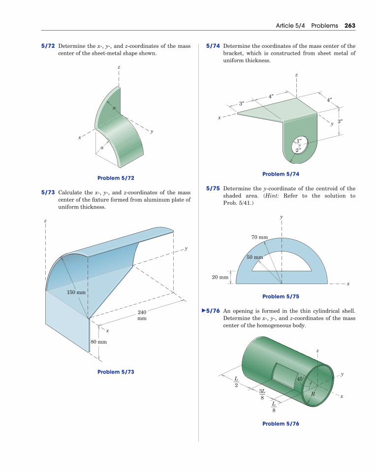
5/72 Determine the x-, y-, and z-coordinates of the masscenter of the sheet-metal shape shown.
Problem 5/72
5/73 Calculate the x-, y-, and z-coordinates of the masscenter of the fixture formed from aluminum plate ofuniform thickness.
Problem 5/73
80 mm
150 mm
240mm
y
z
x
y
z
x
a
a
Article 5/4 Problems 263
5/74 Determine the coordinates of the mass center of thebracket, which is constructed from sheet metal ofuniform thickness.
Problem 5/74
5/75 Determine the y-coordinate of the centroid of theshaded area. (Hint: Refer to the solution to Prob. 5/41.)
Problem 5/75
5/76 An opening is formed in the thin cylindrical shell.Determine the x-, y-, and z-coordinates of the masscenter of the homogeneous body.
Problem 5/76
z
x
y45°
R
L––8
3L––8
L––2
y
x20 mm
50 mm
70 mm
z
xy
2″
1″
3″
4″4″
3″
�
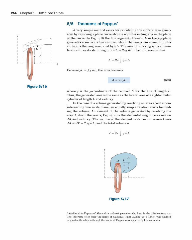
5/5 Theorems of Pappus*A very simple method exists for calculating the surface area gener-
ated by revolving a plane curve about a nonintersecting axis in the planeof the curve. In Fig. 5/16 the line segment of length L in the x-y planegenerates a surface when revolved about the x-axis. An element of thissurface is the ring generated by dL. The area of this ring is its circum-ference times its slant height or dA � 2�y dL. The total area is then
Because the area becomes
(5/8)
where is the y-coordinate of the centroid C for the line of length L.Thus, the generated area is the same as the lateral area of a right-circularcylinder of length L and radius
In the case of a volume generated by revolving an area about a non-intersecting line in its plane, an equally simple relation exists for find-ing the volume. An element of the volume generated by revolving thearea A about the x-axis, Fig. 5/17, is the elemental ring of cross sectiondA and radius y. The volume of the element is its circumference timesdA or dV � 2�y dA, and the total volume is
V � 2� � y dA
y.
y
A � 2�yL
yL � y dL,
A � 2� � y dL
264 Chapter 5 Distributed Forces
x
LdL
C
y
y y –
Figure 5/16
x
y
dA CA
yy–
Figure 5/17
*Attributed to Pappus of Alexandria, a Greek geometer who lived in the third century A.D.The theorems often bear the name of Guldinus (Paul Guldin, 1577–1643), who claimedoriginal authorship, although the works of Pappus were apparently known to him.
Because the volume becomes
(5/9)
where is the y-coordinate of the centroid C of the revolved area A.Thus, we obtain the generated volume by multiplying the generatingarea by the circumference of the circular path described by its centroid.
The two theorems of Pappus, expressed by Eqs. 5/8 and 5/9, are use-ful for determining areas and volumes of revolution. They are also usedto find the centroids of plane curves and plane areas when we know thecorresponding areas and volumes created by revolving these figuresabout a nonintersecting axis. Dividing the area or volume by 2� timesthe corresponding line segment length or plane area gives the distancefrom the centroid to the axis.
If a line or an area is revolved through an angle � less than 2�, wecan determine the generated surface or volume by replacing 2� by � inEqs. 5/8 and 5/9. Thus, the more general relations are
(5/8a)
and
(5/9a)
where � is expressed in radians.
V � �yA
A � �yL
y
V � 2�yA
yA � y dA,
Article 5/5 Theorems of Pappus 265
Another view of the Millau Viaduct in southern France, which appears onthe cover. Note that the full height of the pylons is obscured here.
© Y
an
n G
uic
ha
ou
a/S
up
erS
toc
k
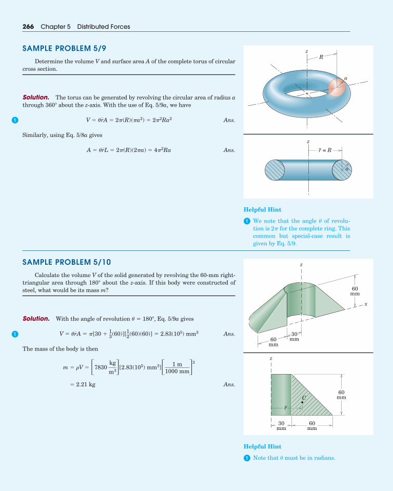
SAMPLE PROBLEM 5/9
Determine the volume V and surface area A of the complete torus of circularcross section.
Solution. The torus can be generated by revolving the circular area of radius athrough 360� about the z-axis. With the use of Eq. 5/9a, we have
Ans.
Similarly, using Eq. 5/8a gives
Ans.A � �rL � 2�(R)(2�a) � 4�2Ra
V � �rA � 2�(R)(�a2) � 2�2Ra2
266 Chapter 5 Distributed Forces
Helpful Hint
� We note that the angle � of revolu-tion is 2� for the complete ring. Thiscommon but special-case result isgiven by Eq. 5/9.
SAMPLE PROBLEM 5/10
Calculate the volume V of the solid generated by revolving the 60-mm right-triangular area through 180� about the z-axis. If this body were constructed ofsteel, what would be its mass m?
Solution. With the angle of revolution � � 180�, Eq. 5/9a gives
Ans.
The mass of the body is then
Ans.� 2.21 kg
m � �V � �7830kg
m3�[2.83(105) mm3]� 1 m1000 mm�
3
V � �rA � �[30 �13(60)][12(60)(60)] � 2.83(105) mm3
Helpful Hint
� Note that � must be in radians.
Rz
a
60mm
60mm
30mm
x
z
60mm
60mm
30mm
z
r–CC
z
r = R–
aa
�
�
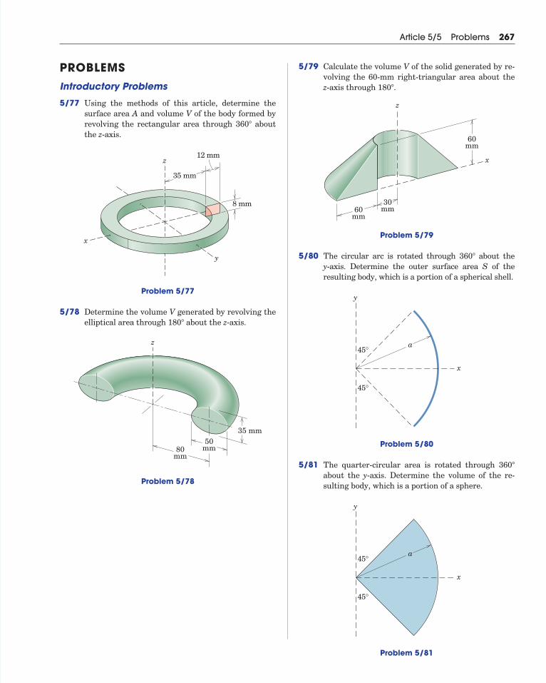
PROBLEMSIntroductory Problems
5/77 Using the methods of this article, determine thesurface area A and volume V of the body formed byrevolving the rectangular area through aboutthe z-axis.
Problem 5/77
5/78 Determine the volume V generated by revolving theelliptical area through about the z-axis.
Problem 5/78
50mm80
mm
35 mm
z
180�
z
x
y
8 mm
35 mm
12 mm
360�
Article 5/5 Problems 267
5/79 Calculate the volume V of the solid generated by re-volving the 60-mm right-triangular area about thez-axis through .
Problem 5/79
5/80 The circular arc is rotated through about the y-axis. Determine the outer surface area S of the resulting body, which is a portion of a spherical shell.
Problem 5/80
5/81 The quarter-circular area is rotated through about the y-axis. Determine the volume of the re-sulting body, which is a portion of a sphere.
Problem 5/81
x
y
45°
45°
a
360�
x
y
45°
45°
a
360�
60mm
60mm
30mm
x
z
180�
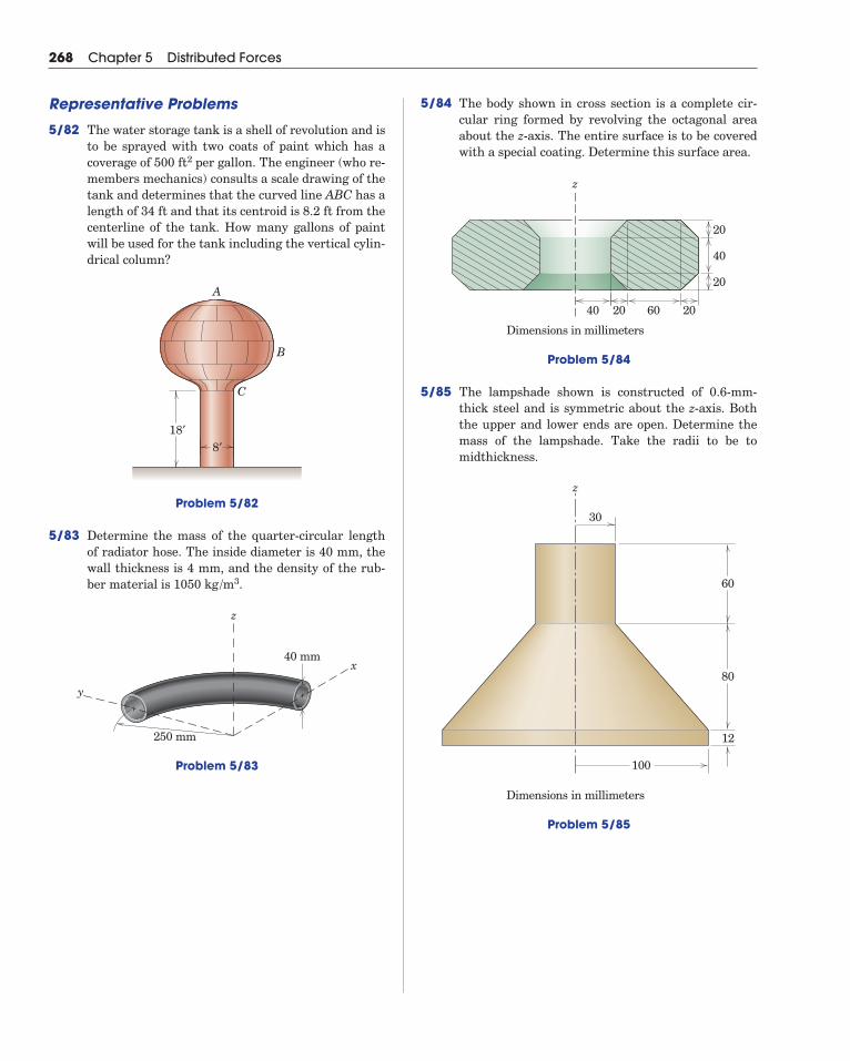
5/84 The body shown in cross section is a complete cir-cular ring formed by revolving the octagonal areaabout the z-axis. The entire surface is to be coveredwith a special coating. Determine this surface area.
Problem 5/84
5/85 The lampshade shown is constructed of 0.6-mm-thick steel and is symmetric about the z-axis. Boththe upper and lower ends are open. Determine themass of the lampshade. Take the radii to be tomidthickness.
Problem 5/85
z
60
30
80
100
12
Dimensions in millimeters
z
60 20
20
20
40
2040
Dimensions in millimeters
268 Chapter 5 Distributed Forces
Representative Problems
5/82 The water storage tank is a shell of revolution and isto be sprayed with two coats of paint which has acoverage of per gallon. The engineer (who re-members mechanics) consults a scale drawing of thetank and determines that the curved line ABC has alength of and that its centroid is from thecenterline of the tank. How many gallons of paintwill be used for the tank including the vertical cylin-drical column?
Problem 5/82
5/83 Determine the mass of the quarter-circular lengthof radiator hose. The inside diameter is 40 mm, thewall thickness is 4 mm, and the density of the rub-ber material is .
Problem 5/83
z
x
y
250 mm
40 mm
1050 kg /m3
18′
A
B
C
8′
8.2 ft34 ft
500 ft2
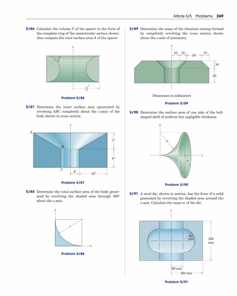
5/86 Calculate the volume V of the spacer in the form ofthe complete ring of the semicircular section shown.Also compute the total surface area A of the spacer.
Problem 5/86
5/87 Determine the inner surface area (generated by revolving ABC completely about the z-axis) of thebody shown in cross section.
Problem 5/87
5/88 Determine the total surface area of the body gener-ated by revolving the shaded area through about the x-axis.
Problem 5/88
x
y
r
360�
4′′ 12′′
7′′
8′′
A
z
B
C
z
1––2 ″1
3––4 ″
Article 5/5 Problems 269
5/89 Determine the mass of the titanium casting formedby completely revolving the cross section shownabout the z-axis of symmetry.
Problem 5/89
5/90 Determine the surface area of one side of the bell-shaped shell of uniform but negligible thickness.
Problem 5/90
5/91 A steel die, shown in section, has the form of a solidgenerated by revolving the shaded area around thez-axis. Calculate the mass m of the die.
Problem 5/91
60 mm
60mm
160 mm
200mm
z
a
z
x
a
z
Dimensions in millimeters
20
20
10
101010
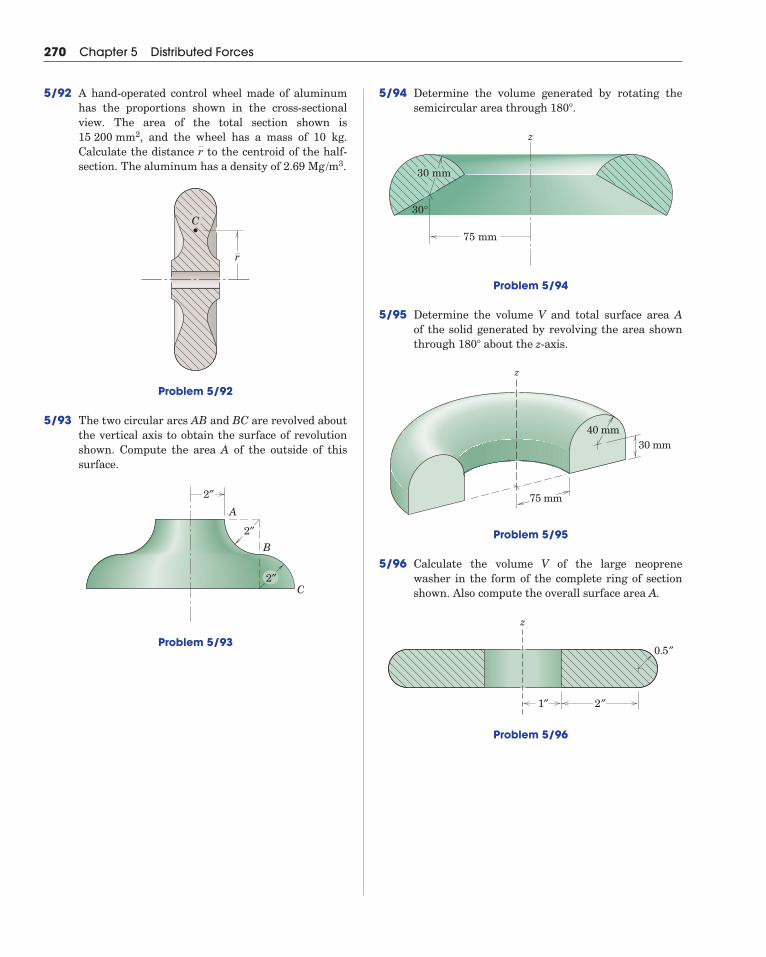
5/94 Determine the volume generated by rotating thesemicircular area through .
Problem 5/94
5/95 Determine the volume V and total surface area Aof the solid generated by revolving the area shownthrough about the z-axis.
Problem 5/95
5/96 Calculate the volume V of the large neoprenewasher in the form of the complete ring of sectionshown. Also compute the overall surface area A.
Problem 5/96
z
0.5″
1″ 2″
40 mm30 mm
z
75 mm
180�
75 mm
z
30°
30 mm
180�
270 Chapter 5 Distributed Forces
5/92 A hand-operated control wheel made of aluminumhas the proportions shown in the cross-sectionalview. The area of the total section shown is
, and the wheel has a mass of 10 kg.Calculate the distance to the centroid of the half-section. The aluminum has a density of .
Problem 5/92
5/93 The two circular arcs AB and BC are revolved aboutthe vertical axis to obtain the surface of revolutionshown. Compute the area A of the outside of thissurface.
Problem 5/93
2″
A
B
C
2″
2″
r
CC
2.69 Mg /m3r
15 200 mm2
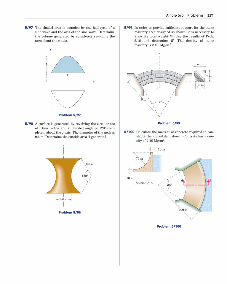
5/97 The shaded area is bounded by one half-cycle of asine wave and the axis of the sine wave. Determinethe volume generated by completely revolving thearea about the x-axis.
Problem 5/97
5/98 A surface is generated by revolving the circular arcof 0.8-m radius and subtended angle of 120 com-pletely about the z-axis. The diameter of the neck is0.6 m. Determine the outside area A generated.
Problem 5/98
120°
0.8 m
z
0.6 m
�
x
y
b
ac
Article 5/5 Problems 271
5/99 In order to provide sufficient support for the stonemasonry arch designed as shown, it is necessary toknow its total weight W. Use the results of Prob.5/16 and determine W. The density of stone masonry is .
Problem 5/99
5/100 Calculate the mass m of concrete required to con-struct the arched dam shown. Concrete has a den-sity of .
Problem 5/100
A
60°
200 m
A
70 m
10 m
10 mSection A-A
2.40 Mg /m3
2 m
2 m
60°8 m
r
1.5 m
2.40 Mg /m 3
272 Chapter 5 Distributed Forces
SECTION B SPECIAL TOPICS
5/6 Beams—External EffectsBeams are structural members which offer resistance to bending
due to applied loads. Most beams are long prismatic bars, and the loadsare usually applied normal to the axes of the bars.
Beams are undoubtedly the most important of all structural mem-bers, so it is important to understand the basic theory underlyingtheir design. To analyze the load-carrying capacities of a beam wemust first establish the equilibrium requirements of the beam as awhole and any portion of it considered separately. Second, we must es-tablish the relations between the resulting forces and the accompany-ing internal resistance of the beam to support these forces. The firstpart of this analysis requires the application of the principles of stat-ics. The second part involves the strength characteristics of the mater-ial and is usually treated in studies of the mechanics of solids or themechanics of materials.
This article is concerned with the external loading and reactions act-ing on a beam. In Art. 5/7 we calculate the distribution along the beamof the internal force and moment.
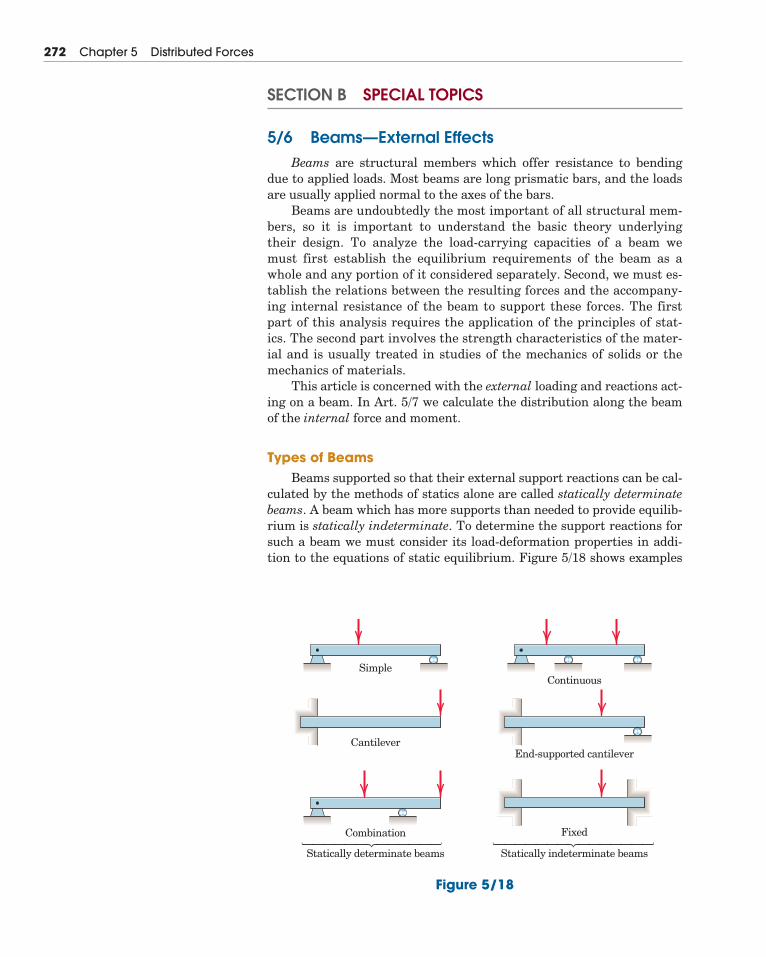
Types of BeamsBeams supported so that their external support reactions can be cal-
culated by the methods of statics alone are called statically determinatebeams. A beam which has more supports than needed to provide equilib-rium is statically indeterminate. To determine the support reactions forsuch a beam we must consider its load-deformation properties in addi-tion to the equations of static equilibrium. Figure 5/18 shows examples
Simple
Cantilever
Continuous
Combination
Statically determinate beams Statically indeterminate beams
End-supported cantilever
Fixed⎫⎪⎪⎪⎪⎪⎬⎪⎪⎪⎪⎪⎭ ⎫⎪⎪⎪⎪⎪⎪⎬⎪⎪⎪⎪⎪⎪⎭
Figure 5/18
of both types of beams. In this article we will analyze statically determi-nate beams only.
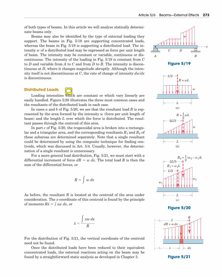
Beams may also be identified by the type of external loading theysupport. The beams in Fig. 5/18 are supporting concentrated loads,whereas the beam in Fig. 5/19 is supporting a distributed load. The in-tensity w of a distributed load may be expressed as force per unit lengthof beam. The intensity may be constant or variable, continuous or dis-continuous. The intensity of the loading in Fig. 5/19 is constant from Cto D and variable from A to C and from D to B. The intensity is discon-tinuous at D, where it changes magnitude abruptly. Although the inten-sity itself is not discontinuous at C, the rate of change of intensity dw/dxis discontinuous.
Distributed LoadsLoading intensities which are constant or which vary linearly are
easily handled. Figure 5/20 illustrates the three most common cases andthe resultants of the distributed loads in each case.
In cases a and b of Fig. 5/20, we see that the resultant load R is rep-resented by the area formed by the intensity w (force per unit length ofbeam) and the length L over which the force is distributed. The resul-tant passes through the centroid of this area.
In part c of Fig. 5/20, the trapezoidal area is broken into a rectangu-lar and a triangular area, and the corresponding resultants R1 and R2 ofthese subareas are determined separately. Note that a single resultantcould be determined by using the composite technique for finding cen-troids, which was discussed in Art. 5/4. Usually, however, the determi-nation of a single resultant is unnecessary.
For a more general load distribution, Fig. 5/21, we must start with adifferential increment of force dR � w dx. The total load R is then thesum of the differential forces, or
As before, the resultant R is located at the centroid of the area underconsideration. The x-coordinate of this centroid is found by the principleof moments � xw dx, or
For the distribution of Fig. 5/21, the vertical coordinate of the centroidneed not be found.
Once the distributed loads have been reduced to their equivalentconcentrated loads, the external reactions acting on the beam may befound by a straightforward static analysis as developed in Chapter 3.
x �� xw dx
R
Rx
R � � w dx
Article 5/6 Beams—External Effects 273
A
x
w
C D
B
Figure 5/19
L/2R = wL
L
(a)
2L/3
L
(b)
R = wL1–2
L/2
L
(c)
R1 = w1L2L/3
R2 = (w2 – w1)L1–2
w1
w
w
w2
Figure 5/20
– R
dxx
dR = wdxx
w
Figure 5/21
SAMPLE PROBLEM 5/11
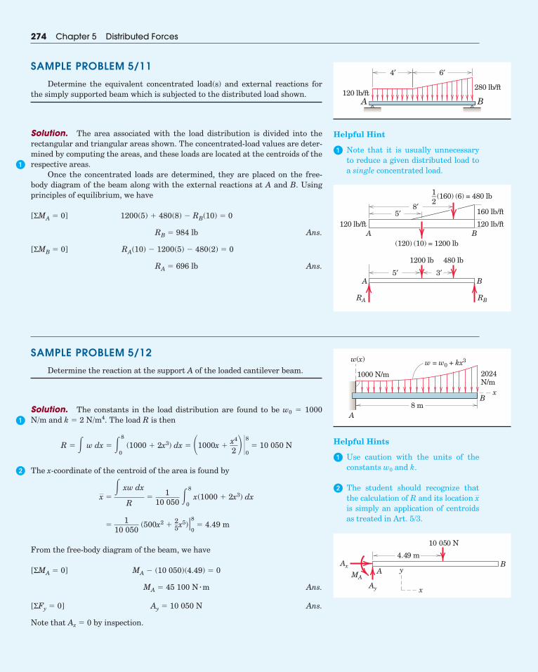
Determine the equivalent concentrated load(s) and external reactions forthe simply supported beam which is subjected to the distributed load shown.
Solution. The area associated with the load distribution is divided into therectangular and triangular areas shown. The concentrated-load values are deter-mined by computing the areas, and these loads are located at the centroids of therespective areas.
Once the concentrated loads are determined, they are placed on the free-body diagram of the beam along with the external reactions at A and B. Usingprinciples of equilibrium, we have
Ans.
Ans.RA � 696 lb
RA(10) � 1200(5) � 480(2) � 0[ΣMB � 0]
RB � 984 lb
1200(5) � 480(8) � RB(10) � 0[ΣMA � 0]
274 Chapter 5 Distributed Forces
A8 m
B
w(x)
1000 N/m 2024N/m
x
w = w0 + kx3
5′8′
120 lb/ft 120 lb/ft
160 lb/ft
(120) (10) = 1200 lb
(160) (6) = 480 lb
1200 lb 480 lb
5′A
RA RB
A B
B3′
1–2
A B
4′ 6′
120 lb/ft280 lb/ft
4.49 m
Ay
AAx B
MA
10 050 N
y
x
Helpful Hint
� Note that it is usually unnecessaryto reduce a given distributed load toa single concentrated load.
SAMPLE PROBLEM 5/12
Determine the reaction at the support A of the loaded cantilever beam.
Solution. The constants in the load distribution are found to be w0 � 1000N/m and k � 2 N/m4. The load R is then
The x-coordinate of the centroid of the area is found by
From the free-body diagram of the beam, we have
Ans.
Ans.
Note that Ax � 0 by inspection.
Ay � 10 050 N[ΣFy � 0]
MA � 45 100 N � m
MA � (10 050)(4.49) � 0[ΣMA � 0]
�1
10 050 (500x2 �
25x5)�8
0� 4.49 m
x �� xw dx
R�
110 050
�8
0x(1000 � 2x3) dx
R � � w dx � �8
0 (1000 � 2x3) dx � �1000x �
x4
2 �80 � 10 050 N Helpful Hints
� Use caution with the units of theconstants w0 and k.
� The student should recognize thatthe calculation of R and its location is simply an application of centroidsas treated in Art. 5/3.
x
�
�
�
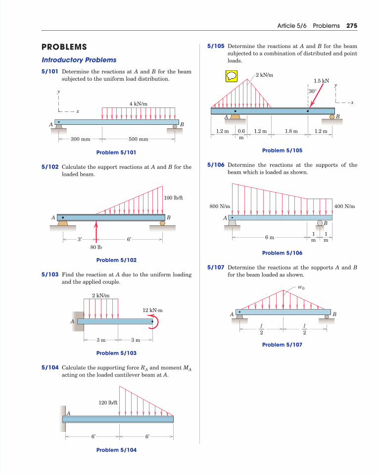
PROBLEMSIntroductory Problems
5/101 Determine the reactions at A and B for the beamsubjected to the uniform load distribution.
Problem 5/101
5/102 Calculate the support reactions at A and B for theloaded beam.
Problem 5/102
5/103 Find the reaction at A due to the uniform loadingand the applied couple.
Problem 5/103
5/104 Calculate the supporting force and moment acting on the loaded cantilever beam at A.
Problem 5/104
A
6′
120 lb/ft
6′
MARA
A
2 kN/m
12 kN.m
3 m 3 m
3′
A B
6′80 lb
100 lb/ft
4 kN/m
300 mm
A B
500 mm
y
x
Article 5/6 Problems 275
5/105 Determine the reactions at A and B for the beamsubjected to a combination of distributed and pointloads.
Problem 5/105
5/106 Determine the reactions at the supports of thebeam which is loaded as shown.
Problem 5/106
5/107 Determine the reactions at the supports A and Bfor the beam loaded as shown.
Problem 5/107
A B
w0
l––2
l––2
6 m1m
1m
AB
800 N/m 400 N/m
A B
1.5 kN2 kN/m
30°
1.2 m 0.6m
1.2 m 1.8 m 1.2 m
x
y
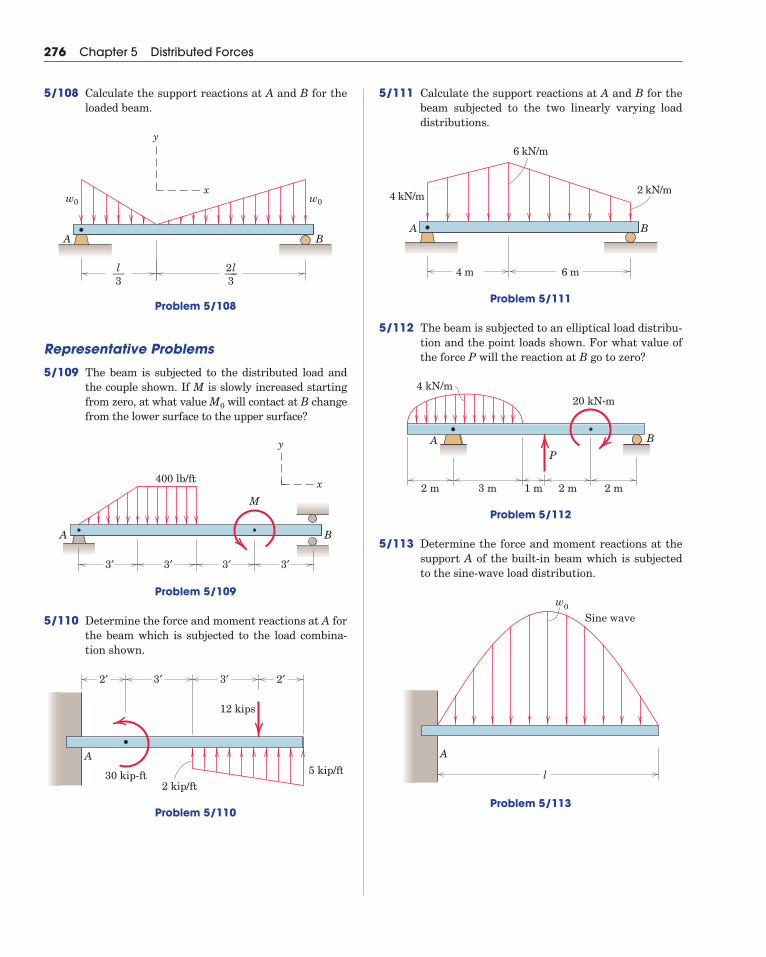
5/111 Calculate the support reactions at A and B for thebeam subjected to the two linearly varying loaddistributions.
Problem 5/111
5/112 The beam is subjected to an elliptical load distribu-tion and the point loads shown. For what value ofthe force P will the reaction at B go to zero?
Problem 5/112
5/113 Determine the force and moment reactions at thesupport A of the built-in beam which is subjectedto the sine-wave load distribution.
Problem 5/113
A
w0
Sine wave
l
A
4 kN/m20 kN·m
2 m2 m2 m 1 m3 m
B
P
A
4 kN/m 2 kN/m
6 kN/m
6 m4 m
B
276 Chapter 5 Distributed Forces
5/108 Calculate the support reactions at A and B for theloaded beam.
Problem 5/108
Representative Problems
5/109 The beam is subjected to the distributed load andthe couple shown. If M is slowly increased startingfrom zero, at what value will contact at B changefrom the lower surface to the upper surface?
Problem 5/109
5/110 Determine the force and moment reactions at A forthe beam which is subjected to the load combina-tion shown.
Problem 5/110
5 kip/ftA
30 kip-ft2 kip/ft
12 kips
2′ 2′3′ 3′
A B
y
x
3′ 3′ 3′
M
3′
400 lb/ft
M0
A B
w0w0
2l–––3
l––3
y
x
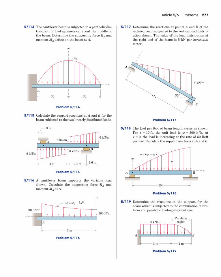
5/114 The cantilever beam is subjected to a parabolic dis-tribution of load symmetrical about the middle ofthe beam. Determine the supporting force andmoment acting on the beam at A.
Problem 5/114
5/115 Calculate the support reactions at A and B for thebeam subjected to the two linearly distributed loads.
Problem 5/115
5/116 A cantilever beam supports the variable loadshown. Calculate the supporting force andmoment at A.
Problem 5/116
A
w = w0 + kx2
w
x500 N/m
6 m
900 N/m
MA
RA
A
B
6 kN/m3 kN/m
3 kN/m6 kN/m
4 m 2.4 m 1.6 m
0.8 m
A
w0
w
x
l/2 l/2
MA
RA
Article 5/6 Problems 277
5/117 Determine the reactions at points A and B of theinclined beam subjected to the vertical load distrib-ution shown. The value of the load distribution atthe right end of the beam is 5 kN per horizontalmeter.
Problem 5/117
5/118 The load per foot of beam length varies as shown.For , the unit load is . At
, the load is increasing at the rate of 50 per foot. Calculate the support reactions at A and B.
Problem 5/118
5/119 Determine the reactions at the support for thebeam which is subjected to the combination of uni-form and parabolic loading distributions.
Problem 5/119
A B
8 kN/mParabolic
region
3 m 2 m
A Bx
ww = k1x – k2 x2
w
10′
lb /ftx � 0w � 300 lb /ftx � 10 ft
A
B
5 kN/m
4 m 30°
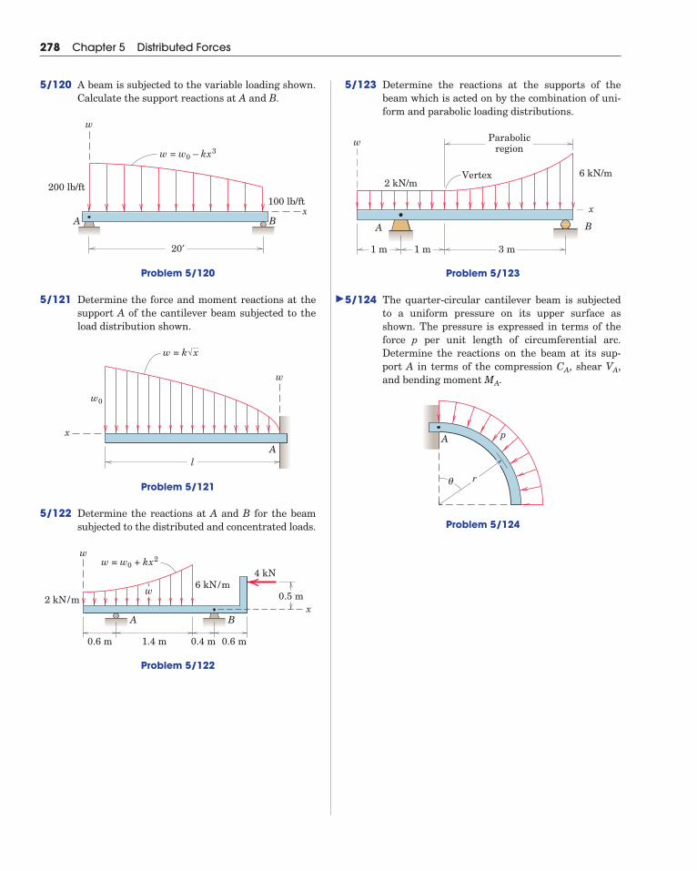
5/123 Determine the reactions at the supports of thebeam which is acted on by the combination of uni-form and parabolic loading distributions.
Problem 5/123
5/124 The quarter-circular cantilever beam is subjectedto a uniform pressure on its upper surface asshown. The pressure is expressed in terms of theforce p per unit length of circumferential arc.Determine the reactions on the beam at its sup-port A in terms of the compression , shear ,and bending moment .
Problem 5/124
θ r
A p
MA
VACA
A B
2 kN/m6 kN/m
1 m 1 m 3 m
Parabolicregion
w
x
Vertex
278 Chapter 5 Distributed Forces
5/120 A beam is subjected to the variable loading shown.Calculate the support reactions at A and B.
Problem 5/120
5/121 Determine the force and moment reactions at thesupport A of the cantilever beam subjected to theload distribution shown.
Problem 5/121
5/122 Determine the reactions at A and B for the beamsubjected to the distributed and concentrated loads.
Problem 5/122
4 kN6 kN/m
w = w0 + kx2
2 kN/m
0.6 m 1.4 m 0.4 m 0.6 m
BA
w
x0.5 mw
w
x
w = k x
w0
lA
A B
w = w0 – kx3
w
x100 lb/ft
20′
200 lb/ft
�
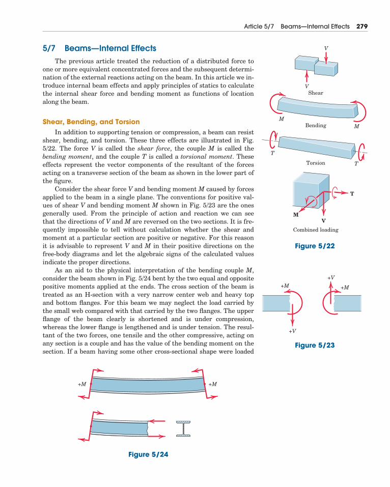
5/7 Beams—Internal EffectsThe previous article treated the reduction of a distributed force to
one or more equivalent concentrated forces and the subsequent determi-nation of the external reactions acting on the beam. In this article we in-troduce internal beam effects and apply principles of statics to calculatethe internal shear force and bending moment as functions of locationalong the beam.
Shear, Bending, and TorsionIn addition to supporting tension or compression, a beam can resist
shear, bending, and torsion. These three effects are illustrated in Fig.5/22. The force V is called the shear force, the couple M is called thebending moment, and the couple T is called a torsional moment. Theseeffects represent the vector components of the resultant of the forcesacting on a transverse section of the beam as shown in the lower part ofthe figure.
Consider the shear force V and bending moment M caused by forcesapplied to the beam in a single plane. The conventions for positive val-ues of shear V and bending moment M shown in Fig. 5/23 are the onesgenerally used. From the principle of action and reaction we can seethat the directions of V and M are reversed on the two sections. It is fre-quently impossible to tell without calculation whether the shear andmoment at a particular section are positive or negative. For this reasonit is advisable to represent V and M in their positive directions on thefree-body diagrams and let the algebraic signs of the calculated valuesindicate the proper directions.
As an aid to the physical interpretation of the bending couple M,consider the beam shown in Fig. 5/24 bent by the two equal and oppositepositive moments applied at the ends. The cross section of the beam istreated as an H-section with a very narrow center web and heavy topand bottom flanges. For this beam we may neglect the load carried bythe small web compared with that carried by the two flanges. The upperflange of the beam clearly is shortened and is under compression,whereas the lower flange is lengthened and is under tension. The resul-tant of the two forces, one tensile and the other compressive, acting onany section is a couple and has the value of the bending moment on thesection. If a beam having some other cross-sectional shape were loaded
Article 5/7 Beams—Internal Effects 279
V
V
M
T
T
MV
T
M
Shear
Bending
Torsion
Combined loading
Figure 5/22
+M +M
+V
+V
Figure 5/23
+M +M
Figure 5/24

in the same way, the distribution of force over the cross section wouldbe different, but the resultant would be the same couple.
Shear-Force and Bending-Moment DiagramsThe variation of shear force V and bending moment M over the
length of a beam provides information necessary for the design analysisof the beam. In particular, the maximum magnitude of the bending mo-ment is usually the primary consideration in the design or selection of abeam, and its value and position should be determined. The variationsin shear and moment are best shown graphically, and the expressionsfor V and M when plotted against distance along the beam give theshear-force and bending-moment diagrams for the beam.
The first step in the determination of the shear and moment rela-tions is to establish the values of all external reactions on the beam byapplying the equations of equilibrium to a free-body diagram of thebeam as a whole. Next, we isolate a portion of the beam, either to theright or to the left of an arbitrary transverse section, with a free-bodydiagram, and apply the equations of equilibrium to this isolated portionof the beam. These equations will yield expressions for the shear force Vand bending moment M acting at the cut section on the part of the beamisolated. The part of the beam which involves the smaller number offorces, either to the right or to the left of the arbitrary section, usuallyyields the simpler solution.
We should avoid using a transverse section which coincides with thelocation of a concentrated load or couple, as such a position represents apoint of discontinuity in the variation of shear or bending moment. Fi-nally, it is important to note that the calculations for V and M on eachsection chosen should be consistent with the positive convention illus-trated in Fig. 5/23.
General Loading, Shear, and Moment RelationshipsFor any beam with distributed loads we can establish certain gen-
eral relationships which will aid greatly in the determination of theshear and moment distributions along the beam. Figure 5/25 representsa portion of a loaded beam, where an element dx of the beam is isolated.The loading w represents the force per unit length of beam. At the loca-tion x the shear V and moment M acting on the element are drawn intheir positive directions. On the opposite side of the element where the
280 Chapter 5 Distributed Forces
w = ƒ(x)
w w
x dx
dx
V
MV + dV
M + dM
Figure 5/25
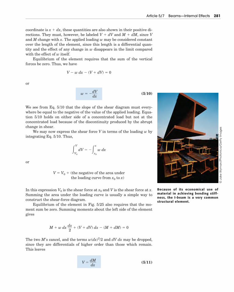
coordinate is x � dx, these quantities are also shown in their positive di-rections. They must, however, be labeled V � dV and M � dM, since Vand M change with x. The applied loading w may be considered constantover the length of the element, since this length is a differential quan-tity and the effect of any change in w disappears in the limit comparedwith the effect of w itself.
Equilibrium of the element requires that the sum of the verticalforces be zero. Thus, we have
or
(5/10)
We see from Eq. 5/10 that the slope of the shear diagram must every-where be equal to the negative of the value of the applied loading. Equa-tion 5/10 holds on either side of a concentrated load but not at theconcentrated load because of the discontinuity produced by the abruptchange in shear.
We may now express the shear force V in terms of the loading w byintegrating Eq. 5/10. Thus,
or
In this expression V0 is the shear force at x0 and V is the shear force at x.Summing the area under the loading curve is usually a simple way toconstruct the shear-force diagram.
Equilibrium of the element in Fig. 5/25 also requires that the mo-ment sum be zero. Summing moments about the left side of the elementgives
The two M’s cancel, and the terms w(dx)2/2 and dV dx may be dropped,since they are differentials of higher order than those which remain.This leaves
(5/11)V �dMdx
M � w dx dx2
� (V � dV) dx � (M � dM) � 0
the loading curve from x0 to x)V � V0 � (the negative of the area under
�V
V0
dV � ��x
x0
w dx
w � �dVdx
V � w dx � (V � dV) � 0
Because of its economical use ofmaterial in achieving bending stiff-ness, the I-beam is a very commonstructural element.
Article 5/7 Beams—Internal Effects 281
© J
ake
Wym
an
/Ph
oto
nic
a/G
ett
y Im
ag
es
which expresses the fact that the shear everywhere is equal to the slopeof the moment curve. Equation 5/11 holds on either side of a concen-trated couple but not at the concentrated couple because of the disconti-nuity caused by the abrupt change in moment.
We may now express the moment M in terms of the shear V by inte-grating Eq. 5/11. Thus,
or
In this expression M0 is the bending moment at x0 and M is the bend-ing moment at x. For beams where there is no externally applied mo-ment M0 at x0 � 0, the total moment at any section equals the areaunder the shear diagram up to that section. Summing the area underthe shear diagram is usually the simplest way to construct the mo-ment diagram.
When V passes through zero and is a continuous function of x withdV/dx � 0, the bending moment M will be a maximum or a minimum,since dM/dx � 0 at such a point. Critical values of M also occur when Vcrosses the zero axis discontinuously, which occurs for beams underconcentrated loads.
We observe from Eqs. 5/10 and 5/11 that the degree of V in x is onehigher than that of w. Also M is of one higher degree in x than is V. Con-sequently, M is two degrees higher in x than w. Thus for a beam loadedby w � kx, which is of the first degree in x, the shear V is of the seconddegree in x and the bending moment M is of the third degree in x.
Equations 5/10 and 5/11 may be combined to yield
(5/12)
Thus, if w is a known function of x, the moment M can be obtained bytwo integrations, provided that the limits of integration are properlyevaluated each time. This method is usable only if w is a continuousfunction of x.*
When bending in a beam occurs in more than a single plane, wemay perform a separate analysis in each plane and combine the resultsvectorially.
d2Mdx2
� �w
M � M0 � (area under the shear diagram from x0 to x)
�M
M0
dM � �x
x0
V dx
282 Chapter 5 Distributed Forces
*When w is a discontinuous function of x, it is possible to introduce a special set of expres-sions called singularity functions which permit writing analytical expressions for shear V andmoment M over an interval which includes discontinuities. These functions are not discussedin this book.
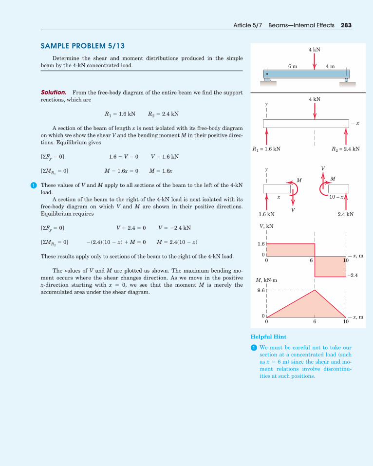
SAMPLE PROBLEM 5/13
Determine the shear and moment distributions produced in the simplebeam by the 4-kN concentrated load.
Solution. From the free-body diagram of the entire beam we find the supportreactions, which are
A section of the beam of length x is next isolated with its free-body diagramon which we show the shear V and the bending moment M in their positive direc-tions. Equilibrium gives
These values of V and M apply to all sections of the beam to the left of the 4-kNload.
A section of the beam to the right of the 4-kN load is next isolated with itsfree-body diagram on which V and M are shown in their positive directions.Equilibrium requires
These results apply only to sections of the beam to the right of the 4-kN load.
The values of V and M are plotted as shown. The maximum bending mo-ment occurs where the shear changes direction. As we move in the positive x-direction starting with x � 0, we see that the moment M is merely theaccumulated area under the shear diagram.
�(2.4)(10 � x) � M � 0 M � 2.4(10 � x)[ΣMR2� 0]
V � 2.4 � 0 V � �2.4 kN[ΣFy � 0]
M � 1.6x � 0 M � 1.6x[ΣMR1� 0]
1.6 � V � 0 V � 1.6 kN[ΣFy � 0]
R1 � 1.6 kN R2 � 2.4 kN
Article 5/7 Beams—Internal Effects 283
�
4 kN
6 m 4 m
4 kNy
y
x
V
V
M M
10 – x
x
R1 = 1.6 kN R2 = 2.4 kN
1.6 kN
1.6
0
0
9.6
0 6
2.4 kN
V, kN
M, kN·m–2.4
10
1060
x, m
x, m
Helpful Hint
� We must be careful not to take oursection at a concentrated load (suchas x � 6 m) since the shear and mo-ment relations involve discontinu-ities at such positions.
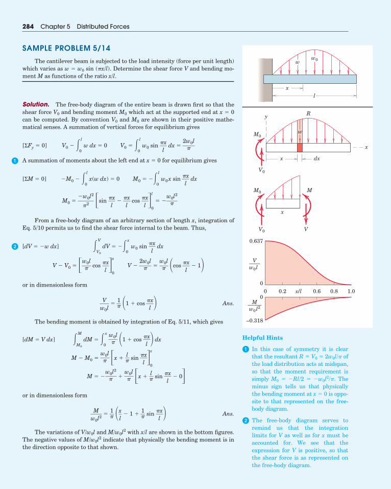
SAMPLE PROBLEM 5/14
The cantilever beam is subjected to the load intensity (force per unit length)which varies as w � w0 sin (�x/l). Determine the shear force V and bending mo-ment M as functions of the ratio x/l.
Solution. The free-body diagram of the entire beam is drawn first so that theshear force V0 and bending moment M0 which act at the supported end at x � 0can be computed. By convention V0 and M0 are shown in their positive mathe-matical senses. A summation of vertical forces for equilibrium gives
A summation of moments about the left end at x � 0 for equilibrium gives
From a free-body diagram of an arbitrary section of length x, integration ofEq. 5/10 permits us to find the shear force internal to the beam. Thus,
or in dimensionless form
Ans.
The bending moment is obtained by integration of Eq. 5/11, which gives
or in dimensionless form
Ans.
The variations of V/w0l and M/w0l2 with x/l are shown in the bottom figures.The negative values of M/w0l2 indicate that physically the bending moment is inthe direction opposite to that shown.
Mw0l2
�1� �x
l� 1 � 1
� sin �xl
M � �w0l2
� �w0l� �x �
l� sin �x
l� 0�
M � M0 �w0l� �x �
l� sin �x
l �x
0
�M
M0
dM � �x
0
w0l� �1 � cos �x
l dx[dM � V dx]
Vw0l
�1� �1 � cos �x
l
V � V0 � �w0l� cos �x
l �x
0
V �2w0l
� �w0l� �cos �x
l� 1
�V
V0
dV � ��x
0w0 sin �x
ldx[dV � �w dx]
M0 ��w0l2
�2 �sin �xl
��xl
cos �xl �
l
0
� �w0l2
�
�M0 � � l
0x(w dx) � 0 M0 � �� l
0w0x sin �x
ldx[ΣM � 0]
V0 � � l
0w dx � 0 V0 � � l
0w0 sin �x
ldx �
2w0l�[ΣFy � 0]
284 Chapter 5 Distributed Forces
x
ww0
l
w
R
x
y
x
x
dx
M0
V0
M0
V0
M
V
0.637
0
0
–0.318
V——w0l
M——–w0 l2
0.20 0.6 0.8 1.0x/l
Helpful Hints
� In this case of symmetry it is clearthat the resultant R � V0 � 2w0l/� ofthe load distribution acts at midspan,so that the moment requirement issimply M0 � �Rl/2 � �w0l2/�. Theminus sign tells us that physicallythe bending moment at x � 0 is oppo-site to that represented on the free-body diagram.
� The free-body diagram serves to remind us that the integration limits for V as well as for x must beaccounted for. We see that the expression for V is positive, so thatthe shear force is as represented onthe free-body diagram.
�
�
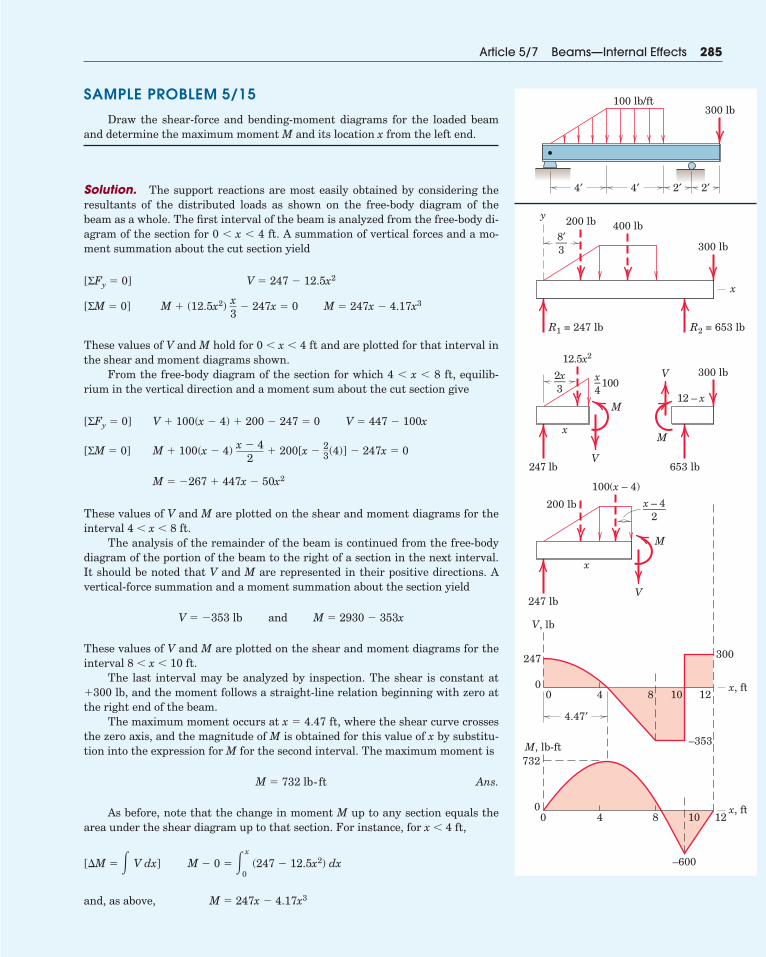
SAMPLE PROBLEM 5/15
Draw the shear-force and bending-moment diagrams for the loaded beamand determine the maximum moment M and its location x from the left end.
Solution. The support reactions are most easily obtained by considering theresultants of the distributed loads as shown on the free-body diagram of thebeam as a whole. The first interval of the beam is analyzed from the free-body di-agram of the section for 0 � x � 4 ft. A summation of vertical forces and a mo-ment summation about the cut section yield
These values of V and M hold for 0 � x � 4 ft and are plotted for that interval inthe shear and moment diagrams shown.
From the free-body diagram of the section for which 4 � x � 8 ft, equilib-rium in the vertical direction and a moment sum about the cut section give
These values of V and M are plotted on the shear and moment diagrams for theinterval 4 � x � 8 ft.
The analysis of the remainder of the beam is continued from the free-bodydiagram of the portion of the beam to the right of a section in the next interval.It should be noted that V and M are represented in their positive directions. Avertical-force summation and a moment summation about the section yield
These values of V and M are plotted on the shear and moment diagrams for theinterval 8 � x � 10 ft.
The last interval may be analyzed by inspection. The shear is constant at�300 lb, and the moment follows a straight-line relation beginning with zero atthe right end of the beam.
The maximum moment occurs at x � 4.47 ft, where the shear curve crossesthe zero axis, and the magnitude of M is obtained for this value of x by substitu-tion into the expression for M for the second interval. The maximum moment is
Ans.
As before, note that the change in moment M up to any section equals thearea under the shear diagram up to that section. For instance, for x � 4 ft,
and, as above, M � 247x � 4.17x3
M � 0 � �x
0 (247 � 12.5x2) dx[�M � � V dx]
M � 732 lb-ft
V � �353 lb and M � 2930 � 353x
M � �267 � 447x � 50x2
M � 100(x � 4) x � 42
� 200[x �23(4)] � 247x � 0[ΣM � 0]
V � 100(x � 4) � 200 � 247 � 0 V � 447 � 100x[ΣFy � 0]
M � (12.5x2) x3
� 247x � 0 M � 247x � 4.17x3[ΣM � 0]
V � 247 � 12.5x2[ΣFy � 0]
Article 5/7 Beams—Internal Effects 285
100 lb/ft300 lb
4′ 4′ 2′ 2′
300 lb
400 lb200 lb8′––3
2x––3
x – 4––––2
x–4
y
x
x, ft
R1 = 247 lb R2 = 653 lb
300 lb
653 lb
12.5x2
100
x
247 lbV
M
M
V
247 lb
V, lb
M, lb-ft
200 lb
V
M
12 – x
100(x – 4)
x
x, ft
4.47′
0 4
4 8
8 10
10 12
120
247
732
00
300
–353
–600
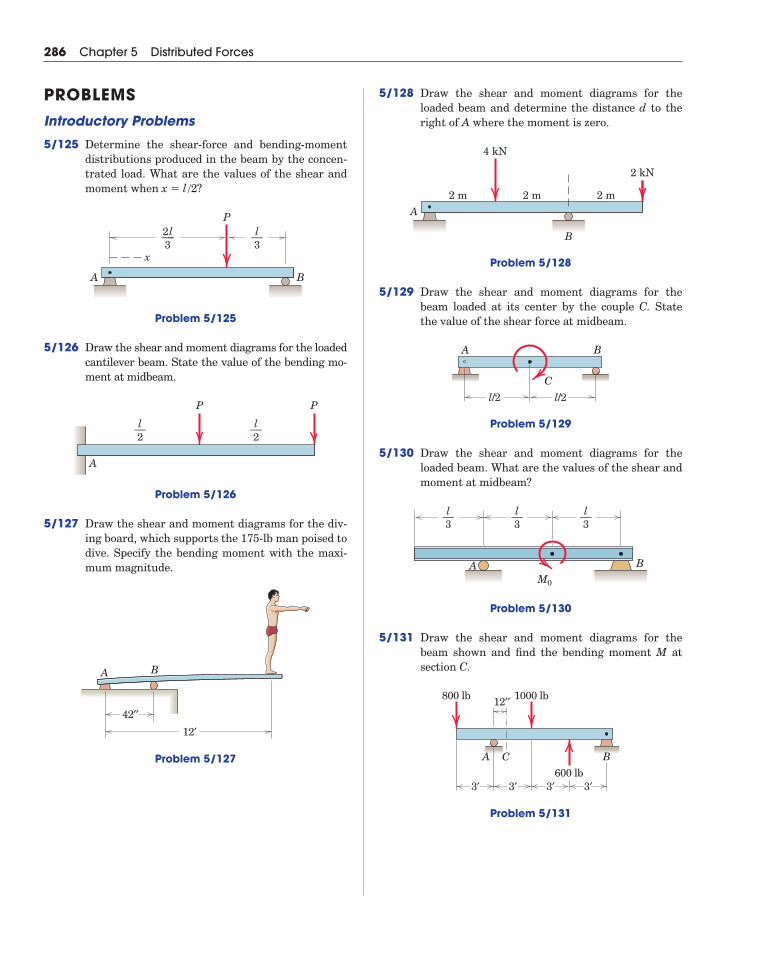
5/128 Draw the shear and moment diagrams for theloaded beam and determine the distance d to theright of A where the moment is zero.
Problem 5/128
5/129 Draw the shear and moment diagrams for thebeam loaded at its center by the couple C. Statethe value of the shear force at midbeam.
Problem 5/129
5/130 Draw the shear and moment diagrams for theloaded beam. What are the values of the shear andmoment at midbeam?
Problem 5/130
5/131 Draw the shear and moment diagrams for thebeam shown and find the bending moment M atsection C.
Problem 5/131
A
3′
C B
3′
12′′800 lb 1000 lb
3′ 3′600 lb
A BM0
l––3
l––3
l––3
A
C
B
l/2 l/2
A
B
4 kN
2 kN
2 m 2 m 2 m
286 Chapter 5 Distributed Forces
PROBLEMSIntroductory Problems
5/125 Determine the shear-force and bending-momentdistributions produced in the beam by the concen-trated load. What are the values of the shear andmoment when
Problem 5/125
5/126 Draw the shear and moment diagrams for the loadedcantilever beam. State the value of the bending mo-ment at midbeam.
Problem 5/126
5/127 Draw the shear and moment diagrams for the div-ing board, which supports the 175-lb man poised todive. Specify the bending moment with the maxi-mum magnitude.
Problem 5/127
BA
42′′
12′
l––2
l––2
PP
A
x
A B
P2l–––3
l––3
x � l /2?
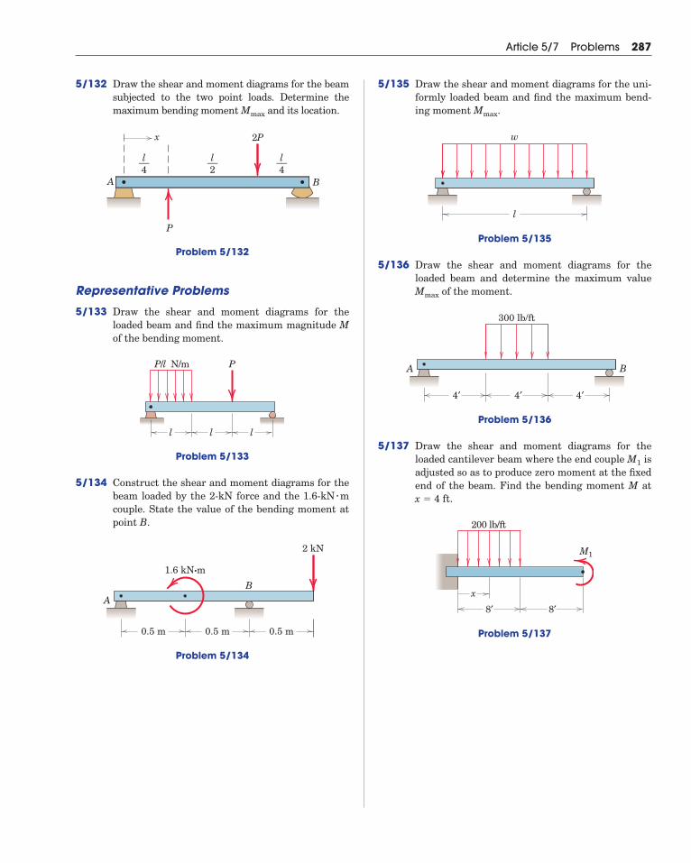
5/132 Draw the shear and moment diagrams for the beamsubjected to the two point loads. Determine themaximum bending moment and its location.
Problem 5/132
Representative Problems
5/133 Draw the shear and moment diagrams for theloaded beam and find the maximum magnitude Mof the bending moment.
Problem 5/133
5/134 Construct the shear and moment diagrams for thebeam loaded by the 2-kN force and the 1.6-kN mcouple. State the value of the bending moment atpoint B.
Problem 5/134
A
B
2 kN
0.5 m 0.5 m 0.5 m
1.6 kN·m
�
l
P/l N/m P
ll
A
x
B
2P
P
l––4
l––2
l––4
Mmax
Article 5/7 Problems 287
5/135 Draw the shear and moment diagrams for the uni-formly loaded beam and find the maximum bend-ing moment .
Problem 5/135
5/136 Draw the shear and moment diagrams for theloaded beam and determine the maximum value
of the moment.
Problem 5/136
5/137 Draw the shear and moment diagrams for theloaded cantilever beam where the end couple isadjusted so as to produce zero moment at the fixedend of the beam. Find the bending moment M at
.
Problem 5/137
200 lb/ft
M1
8′ 8′
x
x � 4 ft
M1
300 lb/ft
4′4′4′
A B
Mmax
w
l
Mmax
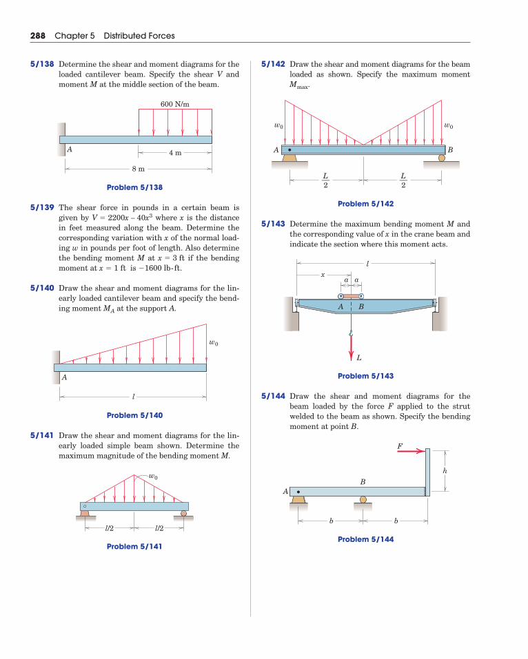
5/142 Draw the shear and moment diagrams for the beamloaded as shown. Specify the maximum moment
.
Problem 5/142
5/143 Determine the maximum bending moment M andthe corresponding value of x in the crane beam andindicate the section where this moment acts.
Problem 5/143
5/144 Draw the shear and moment diagrams for thebeam loaded by the force F applied to the strutwelded to the beam as shown. Specify the bendingmoment at point B.
Problem 5/144
AB
b b
h
F
L
a ax
l
A B
A B
w0w0
L––2
L––2
Mmax
288 Chapter 5 Distributed Forces
5/138 Determine the shear and moment diagrams for theloaded cantilever beam. Specify the shear V andmoment M at the middle section of the beam.
Problem 5/138
5/139 The shear force in pounds in a certain beam isgiven by where x is the distancein feet measured along the beam. Determine thecorresponding variation with x of the normal load-ing w in pounds per foot of length. Also determinethe bending moment M at if the bendingmoment at is .
5/140 Draw the shear and moment diagrams for the lin-early loaded cantilever beam and specify the bend-ing moment at the support A.
Problem 5/140
5/141 Draw the shear and moment diagrams for the lin-early loaded simple beam shown. Determine themaximum magnitude of the bending moment M.
Problem 5/141
l/2 l/2
w0
A
l
w0
MA
�1600 lb-ftx � 1 ft x � 3 ft
V � 2200x – 40x3
600 N/m
8 m
4 mA
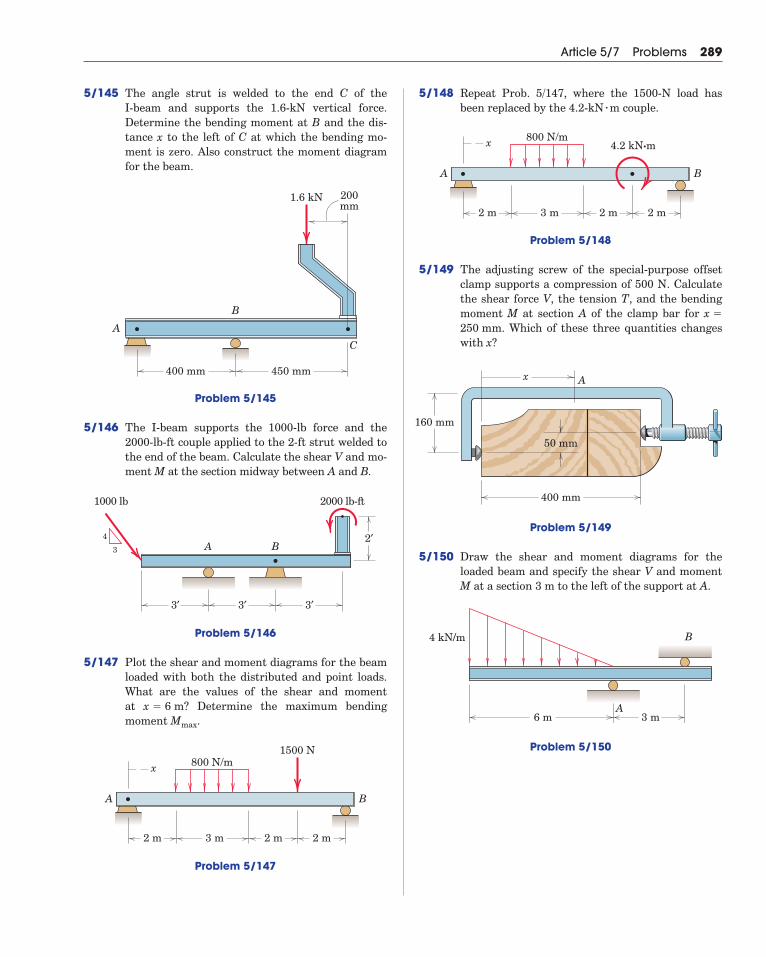
5/145 The angle strut is welded to the end C of the I-beam and supports the 1.6-kN vertical force. Determine the bending moment at B and the dis-tance x to the left of C at which the bending mo-ment is zero. Also construct the moment diagramfor the beam.
Problem 5/145
5/146 The I-beam supports the 1000-lb force and the2000-lb-ft couple applied to the 2-ft strut welded tothe end of the beam. Calculate the shear V and mo-ment M at the section midway between A and B.
Problem 5/146
5/147 Plot the shear and moment diagrams for the beamloaded with both the distributed and point loads.What are the values of the shear and moment at Determine the maximum bending moment .
Problem 5/147
A B
800 N/m1500 N
x
2 m 2 m2 m3 m
Mmax
x � 6 m?
3′
BA
2000 lb-ft1000 lb
3′ 3′
2′3
4
A
B
C
450 mm400 mm
200mm
1.6 kN
Article 5/7 Problems 289
5/148 Repeat Prob. 5/147, where the 1500-N load hasbeen replaced by the 4.2-kN m couple.
Problem 5/148
5/149 The adjusting screw of the special-purpose offsetclamp supports a compression of 500 N. Calculatethe shear force V, the tension T, and the bendingmoment M at section A of the clamp bar for
. Which of these three quantities changeswith x?250 mm
x �
A B
800 N/m4.2 kN·mx
2 m 2 m2 m3 m
�
50 mm
x A
400 mm
160 mm
Problem 5/149
5/150 Draw the shear and moment diagrams for theloaded beam and specify the shear V and momentM at a section 3 m to the left of the support at A.
Problem 5/150
3 m6 m
4 kN/m
A
B
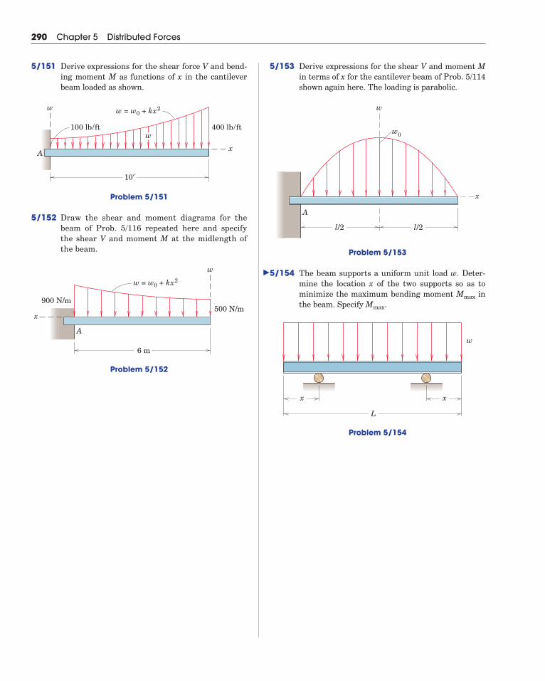
5/153 Derive expressions for the shear V and moment Min terms of x for the cantilever beam of Prob. 5/114shown again here. The loading is parabolic.
Problem 5/153
5/154 The beam supports a uniform unit load w. Deter-mine the location x of the two supports so as tominimize the maximum bending moment inthe beam. Specify .
Problem 5/154
L
w
x x
Mmax
Mmax
A
w0
w
x
l/2 l/2
290 Chapter 5 Distributed Forces
5/151 Derive expressions for the shear force V and bend-ing moment M as functions of x in the cantileverbeam loaded as shown.
Problem 5/151
5/152 Draw the shear and moment diagrams for thebeam of Prob. 5/116 repeated here and specifythe shear V and moment M at the midlength ofthe beam.
Problem 5/152
A
w = w0 + kx2
w
x500 N/m
6 m
900 N/m
400 lb/ft100 lb/ft
10′
A
w
x
w = w0 + kx2
w
�
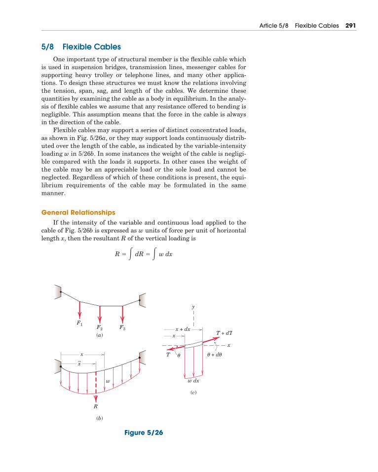
5/8 Flexible CablesOne important type of structural member is the flexible cable which
is used in suspension bridges, transmission lines, messenger cables forsupporting heavy trolley or telephone lines, and many other applica-tions. To design these structures we must know the relations involvingthe tension, span, sag, and length of the cables. We determine thesequantities by examining the cable as a body in equilibrium. In the analy-sis of flexible cables we assume that any resistance offered to bending isnegligible. This assumption means that the force in the cable is alwaysin the direction of the cable.
Flexible cables may support a series of distinct concentrated loads,as shown in Fig. 5/26a, or they may support loads continuously distrib-uted over the length of the cable, as indicated by the variable-intensityloading w in 5/26b. In some instances the weight of the cable is negligi-ble compared with the loads it supports. In other cases the weight ofthe cable may be an appreciable load or the sole load and cannot beneglected. Regardless of which of these conditions is present, the equi-librium requirements of the cable may be formulated in the samemanner.
General RelationshipsIf the intensity of the variable and continuous load applied to the
cable of Fig. 5/26b is expressed as w units of force per unit of horizontallength x, then the resultant R of the vertical loading is
R � � dR � � w dx
Article 5/8 Flexible Cables 291
w dx
F1 F2 F3
(a)
(b)
(c)
–x
x
x + dxT + dT
T
x
y
x
w
R
θ + dθ θ
Figure 5/26
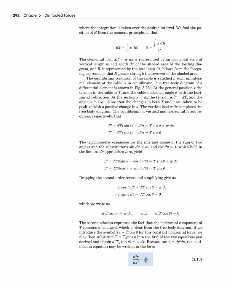
where the integration is taken over the desired interval. We find the po-sition of R from the moment principle, so that
The elemental load dR � w dx is represented by an elemental strip ofvertical length w and width dx of the shaded area of the loading dia-gram, and R is represented by the total area. It follows from the forego-ing expressions that R passes through the centroid of the shaded area.
The equilibrium condition of the cable is satisfied if each infinitesi-mal element of the cable is in equilibrium. The free-body diagram of adifferential element is shown in Fig. 5/26c. At the general position x thetension in the cable is T, and the cable makes an angle � with the hori-zontal x-direction. At the section x � dx the tension is T � dT, and theangle is � � d�. Note that the changes in both T and � are taken to bepositive with a positive change in x. The vertical load w dx completes thefree-body diagram. The equilibrium of vertical and horizontal forces re-quires, respectively, that
The trigonometric expansion for the sine and cosine of the sum of twoangles and the substitutions sin d� � d� and cos d� � 1, which hold inthe limit as d� approaches zero, yield
Dropping the second-order terms and simplifying give us
which we write as
The second relation expresses the fact that the horizontal component ofT remains unchanged, which is clear from the free-body diagram. If weintroduce the symbol T0 � T cos � for this constant horizontal force, wemay then substitute T � T0/cos � into the first of the two equations justderived and obtain d(T0 tan �) � w dx. Because tan � � dy/dx, the equi-librium equation may be written in the form
(5/13)d2y
dx2�
wT0
d(T sin �) � w dx and d(T cos �) � 0
�T sin � d� � dT cos � � 0
T cos � d� � dT sin � � w dx
(T � dT)(cos � � sin � d�) � T cos �
(T � dT)(sin � � cos � d�) � T sin � � w dx
(T � dT) cos (� � d�) � T cos �
(T � dT) sin (� � d�) � T sin � � w dx
Rx � � x dR x �� x dR
R
292 Chapter 5 Distributed Forces
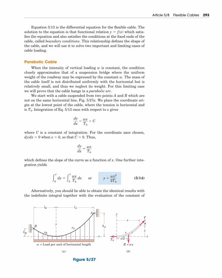
Equation 5/13 is the differential equation for the flexible cable. Thesolution to the equation is that functional relation y � ƒ(x) which satis-fies the equation and also satisfies the conditions at the fixed ends of thecable, called boundary conditions. This relationship defines the shape ofthe cable, and we will use it to solve two important and limiting cases ofcable loading.
Parabolic CableWhen the intensity of vertical loading w is constant, the condition
closely approximates that of a suspension bridge where the uniformweight of the roadway may be expressed by the constant w. The mass ofthe cable itself is not distributed uniformly with the horizontal but isrelatively small, and thus we neglect its weight. For this limiting casewe will prove that the cable hangs in a parabolic arc.
We start with a cable suspended from two points A and B which arenot on the same horizontal line, Fig. 5/27a. We place the coordinate ori-gin at the lowest point of the cable, where the tension is horizontal andis T0. Integration of Eq. 5/13 once with respect to x gives
where C is a constant of integration. For the coordinate axes chosen,dy/dx � 0 when x � 0, so that C � 0. Thus,
which defines the slope of the curve as a function of x. One further inte-gration yields
(5/14)
Alternatively, you should be able to obtain the identical results withthe indefinite integral together with the evaluation of the constant of
�y
0dy � �x
0
wxT0
dx or y �wx2
2T0
dydx
�wxT0
dydx
�wxT0
� C
Article 5/8 Flexible Cables 293
yB
A
sB
sAhA
lA
w = Load per unit of horizontal length
(a)
R = wx
(b)
yhB
lB
xs
x/2T0
y
θx
T
x
Figure 5/27
integration. Equation 5/14 gives the shape of the cable, which we see is avertical parabola. The constant horizontal component of cable tensionbecomes the cable tension at the origin.
Inserting the corresponding values x � lA and y � hA in Eq. 5/14gives
The tension T is found from a free-body diagram of a finite portion ofthe cable, shown in Fig. 5/27b. From the Pythagorean theorem
Elimination of T0 gives
(5/15)
The maximum tension occurs where x � lA and is
(5/15a)
We obtain the length sA of the cable from the origin to point A by in-tegrating the expression for a differential length ds �
Thus,
Although we can integrate this expression in closed form, for computa-tional purposes it is more convenient to express the radical as a conver-gent series and then integrate it term by term. For this purpose we usethe binomial expansion
which converges for x2 � 1. Replacing x in the series by (wx/T0)2 and set-ting n � give the expression
(5/16)
This series is convergent for values of hA/lA � which holds for mostpractical cases.
The relationships which apply to the cable section from the origin topoint B can be easily obtained by replacing hA, lA, and sA by hB, lB, andsB, respectively.
12,
� lA�1 �23 �
hA
lA2
�25 �
hA
lA4
� � � ��
sA � � lA
0�1 �
w2x2
2T0
2�
w4x4
8T0
4� � � � dx
12
(1 � x)n � 1 � nx �n(n � 1)
2!x2 �
n(n � 1)(n � 2)3!
x3 � � � �
� sA
0ds � � lA
0�1 � (dy/dx)2 dx � � lA
0�1 � (wx/T0)2 dx
�(dx)2 � (dy)2.
Tmax � wlA�1 � (lA/2hA)2
T � w�x2 � (lA
2/2hA)2
T � �T0
2 � w2x2
T0 �wlA
2
2hA so that y � hA(x/lA)2
294 Chapter 5 Distributed Forces
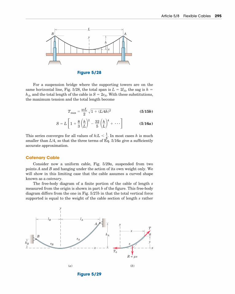
For a suspension bridge where the supporting towers are on thesame horizontal line, Fig. 5/28, the total span is L � 2lA, the sag is h �
hA, and the total length of the cable is S � 2sA. With these substitutions,the maximum tension and the total length become
(5/15b)
(5/16a)
This series converges for all values of h/L � In most cases h is muchsmaller than L/4, so that the three terms of Eq. 5/16a give a sufficientlyaccurate approximation.
Catenary CableConsider now a uniform cable, Fig. 5/29a, suspended from two
points A and B and hanging under the action of its own weight only. Wewill show in this limiting case that the cable assumes a curved shapeknown as a catenary.
The free-body diagram of a finite portion of the cable of length smeasured from the origin is shown in part b of the figure. This free-bodydiagram differs from the one in Fig. 5/27b in that the total vertical forcesupported is equal to the weight of the cable section of length s rather
14.
S � L �1 �83 �h
L2
�325 �h
L4
� � � ��Tmax �
wL2
�1 � (L/4h)2
Article 5/8 Flexible Cables 295
y
h
x
LB A
Figure 5/28
B
A
y
sB
sA
hA
lA
(a) (b)
yhB
lB
xs
T0
y
θx
T
R = sμ
x
Figure 5/29
than the load distributed uniformly with respect to the horizontal. If thecable has a weight � per unit of its length, the resultant R of the load isR � �s, and the incremental vertical load w dx of Fig. 5/26c is replacedby � ds. With this replacement the differential relation, Eq. 5/13, for thecable becomes
(5/17)
Because s � ƒ(x, y), we must change this equation to one containingonly the two variables.
We may substitute the identity (ds)2 � (dx)2 � (dy)2 to obtain
(5/18)
Equation 5/18 is the differential equation of the curve (catenary) formedby the cable. This equation is easier to solve if we substitute p � dy/dxto obtain
Integrating this equation gives us
The constant C is zero because dy/dx � p � 0 when x � 0. Substitutingp � dy/dx, changing to exponential form, and clearing the equation ofthe radical give
where the hyperbolic function* is introduced for convenience. The slopemay be integrated to obtain
The integration constant K is evaluated from the boundary conditionx � 0 when y � 0. This substitution requires that K � �T0/�, andhence,
(5/19)y �T0� �cosh
�xT0
� 1
y �T0� cosh
�xT0
� K
dydx
�e�x/T0 � e��x/T0
2� sinh
�xT0
ln (p � �1 � p2) ��
T0x � C
dp
�1 � p2�
�
T0dx
d2ydx2
��
T0 �1 � �dydx
2
d2y
dx2�
�
T0
dsdx
296 Chapter 5 Distributed Forces
*See Arts. C/8 and C/10, Appendix C, for the definition and integral of hyperbolic functions.
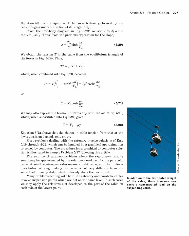
Equation 5/19 is the equation of the curve (catenary) formed by thecable hanging under the action of its weight only.
From the free-body diagram in Fig. 5/29b we see that dy/dx �
tan � � �s/T0. Thus, from the previous expression for the slope,
(5/20)
We obtain the tension T in the cable from the equilibrium triangle ofthe forces in Fig. 5/29b. Thus,
which, when combined with Eq. 5/20, becomes
or
(5/21)
We may also express the tension in terms of y with the aid of Eq. 5/19,which, when substituted into Eq. 5/21, gives
(5/22)
Equation 5/22 shows that the change in cable tension from that at thelowest position depends only on �y.
Most problems dealing with the catenary involve solutions of Eqs.5/19 through 5/22, which can be handled by a graphical approximationor solved by computer. The procedure for a graphical or computer solu-tion is illustrated in Sample Problem 5/17 following this article.
The solution of catenary problems where the sag-to-span ratio issmall may be approximated by the relations developed for the paraboliccable. A small sag-to-span ratio means a tight cable, and the uniformdistribution of weight along the cable is not very different from thesame load intensity distributed uniformly along the horizontal.
Many problems dealing with both the catenary and parabolic cablesinvolve suspension points which are not on the same level. In such caseswe may apply the relations just developed to the part of the cable oneach side of the lowest point.
T � T0 � �y
T � T0 cosh �xT0
T2 � T0
2�1 � sinh2 �xT0 � T0
2 cosh2 �xT0
T2 � �2s2 � T0
2
s �T0� sinh
�xT0
Article 5/8 Flexible Cables 297
In addition to the distributed weightof the cable, these tramway carsexert a concentrated load on thesuspending cable.
© S
usa
na
Ca
rva
lho
/Fo
tolia
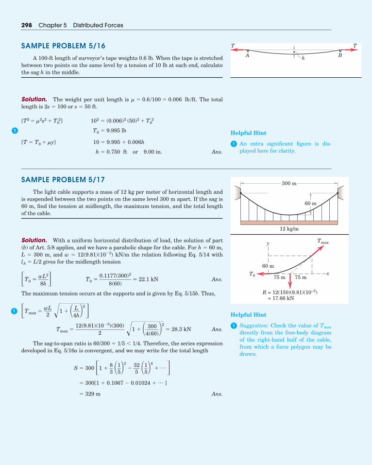
SAMPLE PROBLEM 5/17
The light cable supports a mass of 12 kg per meter of horizontal length andis suspended between the two points on the same level 300 m apart. If the sag is60 m, find the tension at midlength, the maximum tension, and the total lengthof the cable.
Solution. With a uniform horizontal distribution of load, the solution of part(b) of Art. 5/8 applies, and we have a parabolic shape for the cable. For h � 60 m,L � 300 m, and w � 12(9.81)(10�3) kN/m the relation following Eq. 5/14 with lA � L/2 gives for the midlength tension
Ans.
The maximum tension occurs at the supports and is given by Eq. 5/15b. Thus,
Ans.
The sag-to-span ratio is 60/300 � 1/5 � 1/4. Therefore, the series expressiondeveloped in Eq. 5/16a is convergent, and we may write for the total length
Ans.� 329 m
� 300[1 � 0.1067 � 0.01024 � … ]
S � 300 �1 �83 �1
52
�325 �1
54
� …�
Tmax �12(9.81)(10�3)(300)
2 �1 � � 3004(60)
2� 28.3 kN
�Tmax �wL2 �1 � � L
4h2�
T0 �0.1177(300)2
8(60)� 22.1 kN�T0 �
wL2
8h �
298 Chapter 5 Distributed Forces
60 m
300 m
12 kg/m
75 m 75 mxT0
R = 12(150)(9.81)(10–3) = 17.66 kN
Tmaxy
60 m
�Helpful Hint
� Suggestion: Check the value of Tmax
directly from the free-body diagramof the right-hand half of the cable,from which a force polygon may bedrawn.
SAMPLE PROBLEM 5/16
A 100-ft length of surveyor’s tape weights 0.6 lb. When the tape is stretchedbetween two points on the same level by a tension of 10 lb at each end, calculatethe sag h in the middle.
Solution. The weight per unit length is The totallength is or
[ ]
[ ]
in. Ans.h � 0.750 ft or 9.00
10 � 9.995 � 0.006hT � T0 � �y
T0 � 9.995 lb
102 � (0.006)2 (50)2 � T02T2 � �2s2 � T0
2
s � 50 ft.2s � 100� � 0.6 /100 � 0.006 lb /ft.
� Helpful Hint
� An extra significant figure is dis-played here for clarity.
h
T T
BA
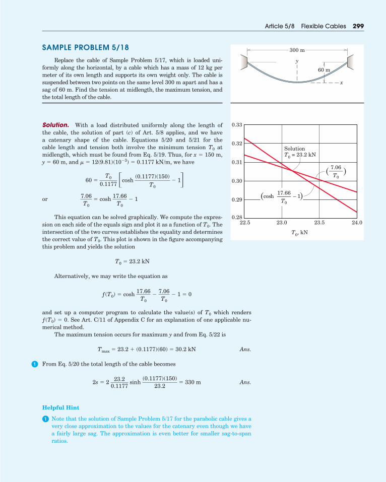
Article 5/8 Flexible Cables 299
�
SAMPLE PROBLEM 5/18
Replace the cable of Sample Problem 5/17, which is loaded uni-formly along the horizontal, by a cable which has a mass of 12 kg permeter of its own length and supports its own weight only. The cable issuspended between two points on the same level 300 m apart and has asag of 60 m. Find the tension at midlength, the maximum tension, andthe total length of the cable.
Solution. With a load distributed uniformly along the length ofthe cable, the solution of part (c) of Art. 5/8 applies, and we havea catenary shape of the cable. Equations 5/20 and 5/21 for thecable length and tension both involve the minimum tension T0 atmidlength, which must be found from Eq. 5/19. Thus, for x � 150 m,y � 60 m, and � � 12(9.81)(10�3) � 0.1177 kN/m, we have
or
This equation can be solved graphically. We compute the expres-sion on each side of the equals sign and plot it as a function of T0. Theintersection of the two curves establishes the equality and determinesthe correct value of T0. This plot is shown in the figure accompanyingthis problem and yields the solution
Alternatively, we may write the equation as
and set up a computer program to calculate the value(s) of T0 which renders ƒ(T0) � 0. See Art. C/11 of Appendix C for an explanation of one applicable nu-merical method.
The maximum tension occurs for maximum y and from Eq. 5/22 is
Ans.
From Eq. 5/20 the total length of the cable becomes
Ans.
Helpful Hint
� Note that the solution of Sample Problem 5/17 for the parabolic cable gives avery close approximation to the values for the catenary even though we havea fairly large sag. The approximation is even better for smaller sag-to-spanratios.
2s � 2 23.20.1177
sinh (0.1177)(150)
23.2� 330 m
Tmax � 23.2 � (0.1177)(60) � 30.2 kN
ƒ(T0) � cosh 17.66T0
�7.06T0
� 1 � 0
T0 � 23.2 kN
7.06T0
� cosh 17.66T0
� 1
60 �T0
0.1177 �cosh(0.1177)(150)
T0� 1�
60 m
300 m
x
y
0.33
SolutionT0 = 23.2 kN
T0, kN
0.32
0.31
0.30
0.29
0.28
7.06——–
T0
22.5 23.0 23.5 24.0
cosh – 117.66——–
T0( (
((
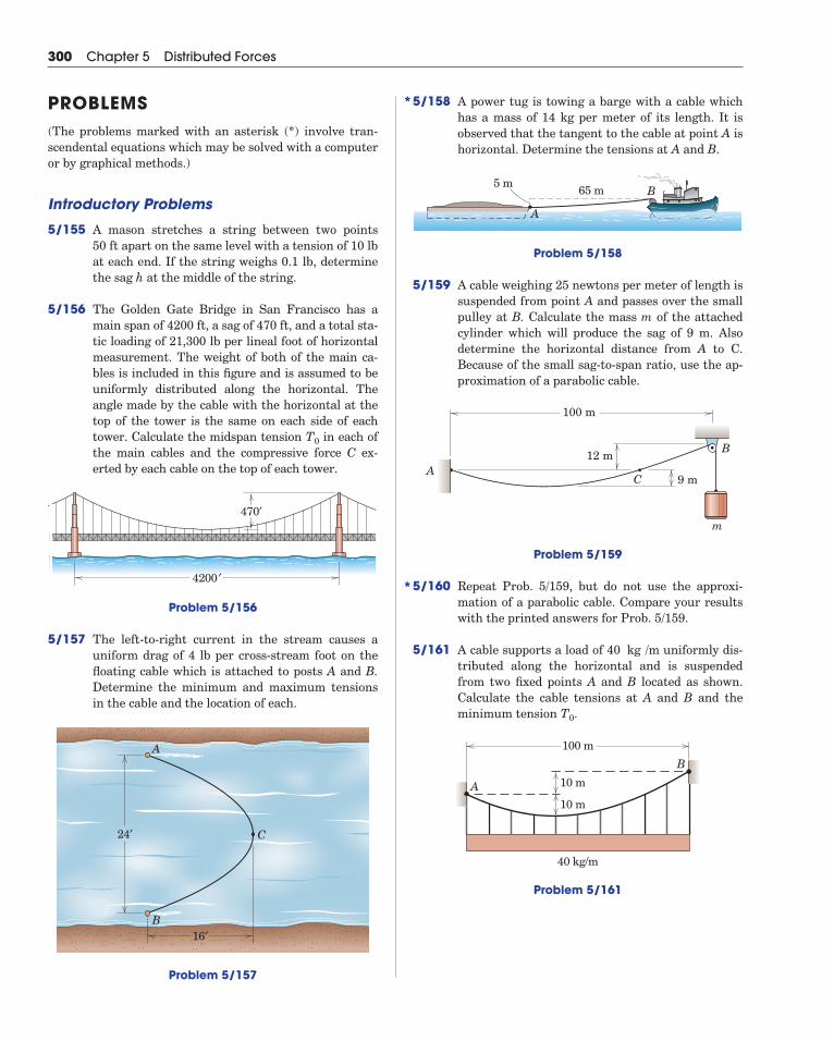
5/158 A power tug is towing a barge with a cable whichhas a mass of 14 kg per meter of its length. It is observed that the tangent to the cable at point A ishorizontal. Determine the tensions at A and B.
Problem 5/158
5/159 A cable weighing 25 newtons per meter of length issuspended from point A and passes over the smallpulley at B. Calculate the mass m of the attachedcylinder which will produce the sag of 9 m. Also determine the horizontal distance from A to C. Because of the small sag-to-span ratio, use the ap-proximation of a parabolic cable.
Problem 5/159
5/160 Repeat Prob. 5/159, but do not use the approxi-mation of a parabolic cable. Compare your resultswith the printed answers for Prob. 5/159.
5/161 A cable supports a load of uniformly dis-tributed along the horizontal and is suspendedfrom two fixed points A and B located as shown.Calculate the cable tensions at A and B and theminimum tension .
Problem 5/161
100 m
40 kg/m
10 m
10 m
A
B
T0
40 kg /m
100 m
12 m
9 mA
B
C
m
5 m65 m
A
B
300 Chapter 5 Distributed Forces
PROBLEMS(The problems marked with an asterisk (*) involve tran-scendental equations which may be solved with a computeror by graphical methods.)
Introductory Problems
5/155 A mason stretches a string between two points 50 ft apart on the same level with a tension of 10 lbat each end. If the string weighs 0.1 lb, determinethe sag h at the middle of the string.
5/156 The Golden Gate Bridge in San Francisco has amain span of 4200 ft, a sag of 470 ft, and a total sta-tic loading of 21,300 lb per lineal foot of horizontalmeasurement. The weight of both of the main ca-bles is included in this figure and is assumed to beuniformly distributed along the horizontal. Theangle made by the cable with the horizontal at thetop of the tower is the same on each side of eachtower. Calculate the midspan tension in each ofthe main cables and the compressive force C ex-erted by each cable on the top of each tower.
Problem 5/156
5/157 The left-to-right current in the stream causes auniform drag of 4 lb per cross-stream foot on thefloating cable which is attached to posts A and B.Determine the minimum and maximum tensionsin the cable and the location of each.
Problem 5/157
16′
24′ C
A
B
4200 ′
470′
T0
*
*
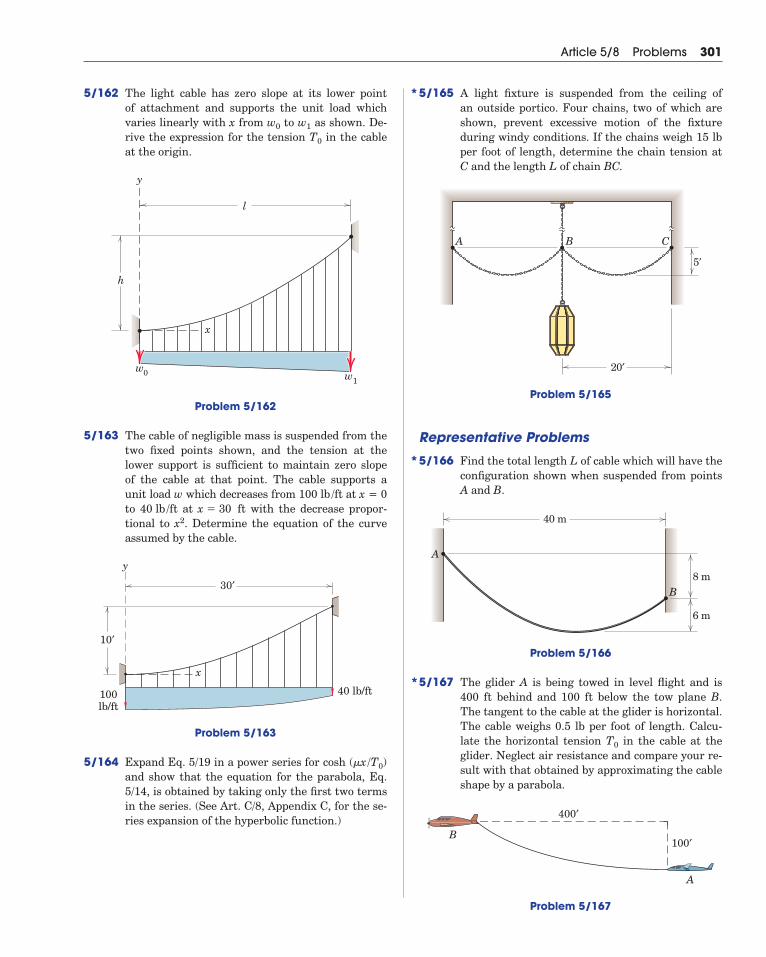
5/162 The light cable has zero slope at its lower point of attachment and supports the unit load whichvaries linearly with x from to as shown. De-rive the expression for the tension in the cableat the origin.
Problem 5/162
5/163 The cable of negligible mass is suspended from thetwo fixed points shown, and the tension at thelower support is sufficient to maintain zero slopeof the cable at that point. The cable supports aunit load w which decreases from at x = 0to at with the decrease propor-tional to . Determine the equation of the curveassumed by the cable.
Problem 5/163
5/164 Expand Eq. 5/19 in a power series for cosh and show that the equation for the parabola, Eq.5/14, is obtained by taking only the first two termsin the series. (See Art. C/8, Appendix C, for the se-ries expansion of the hyperbolic function.)
(�x/T0)
30′
10′
x
y
40 lb/ft100lb/ft
x2x � 30 ft40 lb /ft
100 lb /ft
h
x
y
w0 w1
l
T0
w1w0
Article 5/8 Problems 301
5/165 A light fixture is suspended from the ceiling of an outside portico. Four chains, two of which areshown, prevent excessive motion of the fixtureduring windy conditions. If the chains weigh 15 lbper foot of length, determine the chain tension atC and the length L of chain BC.
Problem 5/165
Representative Problems
5/166 Find the total length L of cable which will have theconfiguration shown when suspended from pointsA and B.
Problem 5/166
5/167 The glider A is being towed in level flight and is400 ft behind and 100 ft below the tow plane B.The tangent to the cable at the glider is horizontal.The cable weighs 0.5 lb per foot of length. Calcu-late the horizontal tension in the cable at theglider. Neglect air resistance and compare your re-sult with that obtained by approximating the cableshape by a parabola.
Problem 5/167
100′
A
400′
B
T0
40 m
8 m
6 m
B
A
B CA
5′
20′
*
*
*
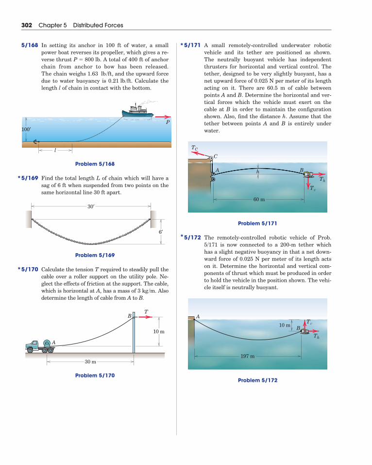
5/171 A small remotely-controlled underwater roboticvehicle and its tether are positioned as shown. The neutrally buoyant vehicle has independentthrusters for horizontal and vertical control. Thetether, designed to be very slightly buoyant, has anet upward force of 0.025 N per meter of its lengthacting on it. There are 60.5 m of cable betweenpoints A and B. Determine the horizontal and ver-tical forces which the vehicle must exert on thecable at B in order to maintain the configurationshown. Also, find the distance h. Assume that thetether between points A and B is entirely underwater.
Problem 5/171
5/172 The remotely-controlled robotic vehicle of Prob.5/171 is now connected to a 200-m tether whichhas a slight negative buoyancy in that a net down-ward force of 0.025 N per meter of its length actson it. Determine the horizontal and vertical com-ponents of thrust which must be produced in orderto hold the vehicle in the position shown. The vehi-cle itself is neutrally buoyant.
Problem 5/172
197 m
10 m
A
BTv
Th
h BA
C
Tv
Th
TC
60 m
302 Chapter 5 Distributed Forces
5/168 In setting its anchor in 100 ft of water, a smallpower boat reverses its propeller, which gives a re-verse thrust . A total of 400 ft of anchorchain from anchor to bow has been released.The chain weighs , and the upward forcedue to water buoyancy is . Calculate thelength l of chain in contact with the bottom.
0.21 lb /ft1.63 lb /ft
P � 800 lb
P
l
100′
Problem 5/168
5/169 Find the total length L of chain which will have asag of 6 ft when suspended from two points on thesame horizontal line 30 ft apart.
Problem 5/169
5/170 Calculate the tension T required to steadily pull thecable over a roller support on the utility pole. Ne-glect the effects of friction at the support. The cable,which is horizontal at A, has a mass of . Alsodetermine the length of cable from A to B.
Problem 5/170
10 m
30 m
B
A
T
3 kg /m
30′
6′
*
*
*
*
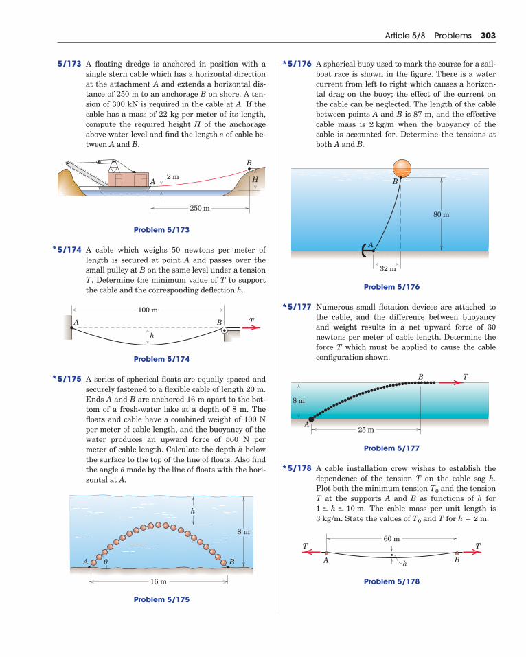
5/173 A floating dredge is anchored in position with asingle stern cable which has a horizontal directionat the attachment A and extends a horizontal dis-tance of 250 m to an anchorage B on shore. A ten-sion of 300 kN is required in the cable at A. If thecable has a mass of 22 kg per meter of its length,compute the required height H of the anchorageabove water level and find the length s of cable be-tween A and B.
Article 5/8 Problems 303
5/176 A spherical buoy used to mark the course for a sail-boat race is shown in the figure. There is a watercurrent from left to right which causes a horizon-tal drag on the buoy; the effect of the current onthe cable can be neglected. The length of the cablebetween points A and B is 87 m, and the effectivecable mass is when the buoyancy of thecable is accounted for. Determine the tensions atboth A and B.
Problem 5/176
5/177 Numerous small flotation devices are attached tothe cable, and the difference between buoyancyand weight results in a net upward force of 30newtons per meter of cable length. Determine theforce T which must be applied to cause the cableconfiguration shown.
Problem 5/177
5/178 A cable installation crew wishes to establish thedependence of the tension T on the cable sag h.Plot both the minimum tension and the tensionT at the supports A and B as functions of h for
. The cable mass per unit length is. State the values of and T for h = 2 m.
Problem 5/178
60 m
h
T T
BA
T03 kg /m1 � h � 10 m
T0
25 m
8 m
B
A
T
32 m
B
A
80 m
2 kg /m
*
*
*
*
*
A
B
250 m
2 m H
Problem 5/173
5/174 A cable which weighs 50 newtons per meter oflength is secured at point A and passes over thesmall pulley at B on the same level under a tensionT. Determine the minimum value of T to supportthe cable and the corresponding deflection h.
Problem 5/174
5/175 A series of spherical floats are equally spaced andsecurely fastened to a flexible cable of length 20 m.Ends A and B are anchored 16 m apart to the bot-tom of a fresh-water lake at a depth of 8 m. Thefloats and cable have a combined weight of 100 Nper meter of cable length, and the buoyancy of thewater produces an upward force of 560 N permeter of cable length. Calculate the depth h belowthe surface to the top of the line of floats. Also findthe angle made by the line of floats with the hori-zontal at A.
Problem 5/175
h
A B
8 m
16 m
θ
�
100 m
A B T
h
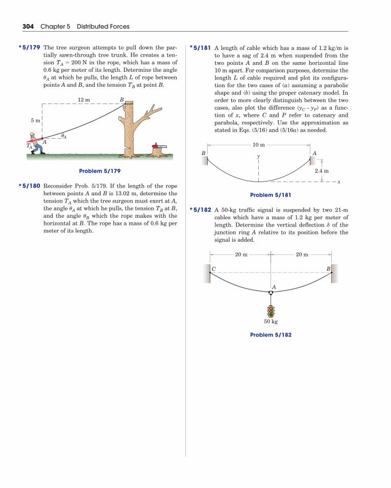
5/181 A length of cable which has a mass of isto have a sag of 2.4 m when suspended from thetwo points A and B on the same horizontal line 10 m apart. For comparison purposes, determine thelength L of cable required and plot its configura-tion for the two cases of (a) assuming a parabolicshape and (b) using the proper catenary model. Inorder to more clearly distinguish between the twocases, also plot the difference as a func-tion of x, where C and P refer to catenary andparabola, respectively. Use the approximation asstated in Eqs. (5/16) and (5/16a) as needed.
Problem 5/181
5/182 A 50-kg traffic signal is suspended by two 21-m cables which have a mass of 1.2 kg per meter oflength. Determine the vertical deflection of thejunction ring A relative to its position before thesignal is added.
Problem 5/182
C B
A
20 m 20 m
50 kg
�
10 m
x
2.4 m
y AB
(yC – yP)
1.2 kg /m
304 Chapter 5 Distributed Forces
5/179 The tree surgeon attempts to pull down the par-tially sawn-through tree trunk. He creates a ten-sion in the rope, which has a mass of0.6 kg per meter of its length. Determine the angle
at which he pulls, the length L of rope betweenpoints A and B, and the tension at point B.
Problem 5/179
5/180 Reconsider Prob. 5/179. If the length of the ropebetween points A and B is 13.02 m, determine thetension which the tree surgeon must exert at A,the angle at which he pulls, the tension at B,and the angle which the rope makes with thehorizontal at B. The rope has a mass of 0.6 kg permeter of its length.
�B
TB�A
TA
5 m
12 m
TAA
B
Aθ
TB
�A
TA � 200 N
*
*
*
*
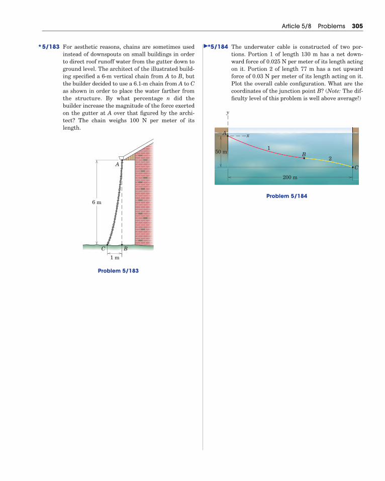
5/183 For aesthetic reasons, chains are sometimes usedinstead of downspouts on small buildings in orderto direct roof runoff water from the gutter down toground level. The architect of the illustrated build-ing specified a 6-m vertical chain from A to B, butthe builder decided to use a 6.1-m chain from A to Cas shown in order to place the water farther fromthe structure. By what percentage n did thebuilder increase the magnitude of the force exertedon the gutter at A over that figured by the archi-tect? The chain weighs 100 N per meter of itslength.
Problem 5/183
6 m
1 m
C
A
B
Article 5/8 Problems 305
5/184 The underwater cable is constructed of two por-tions. Portion 1 of length 130 m has a net down-ward force of 0.025 N per meter of its length actingon it. Portion 2 of length 77 m has a net upwardforce of 0.03 N per meter of its length acting on it.Plot the overall cable configuration. What are thecoordinates of the junction point B? (Note: The dif-ficulty level of this problem is well above average!)
Problem 5/184
200 m
50 m1
2
A
B
C
x
y
* *�
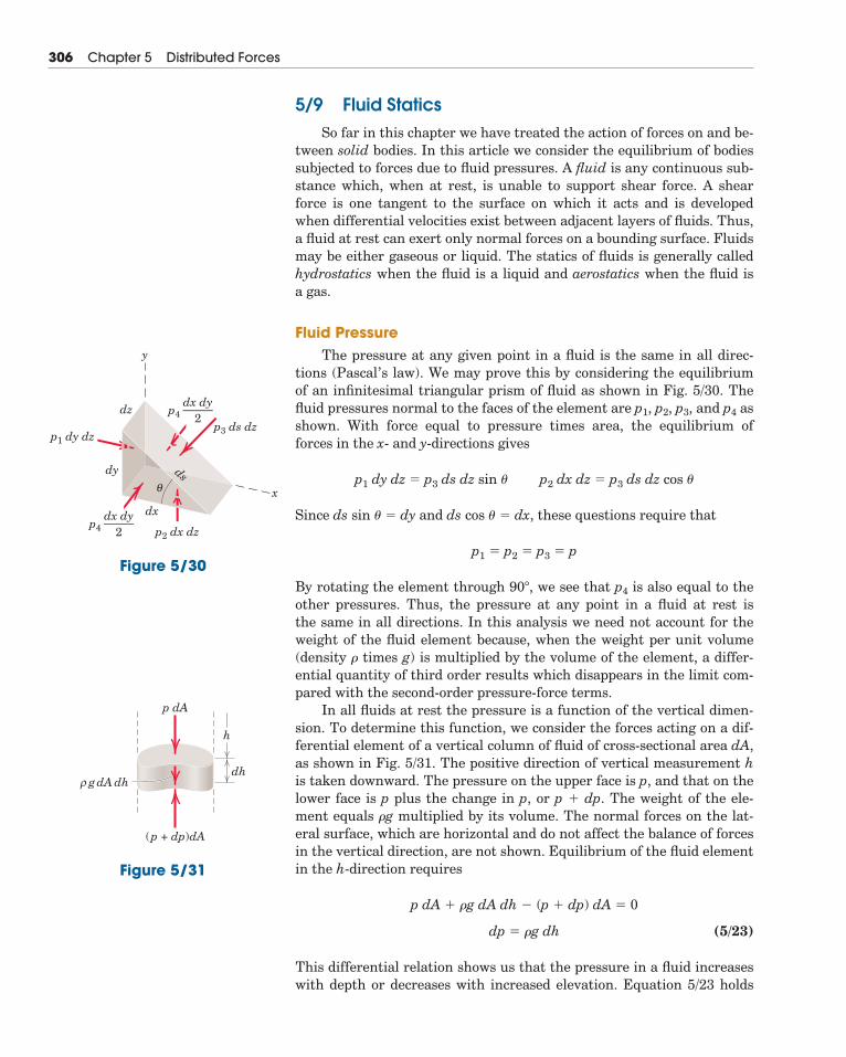
5/9 Fluid StaticsSo far in this chapter we have treated the action of forces on and be-
tween solid bodies. In this article we consider the equilibrium of bodiessubjected to forces due to fluid pressures. A fluid is any continuous sub-stance which, when at rest, is unable to support shear force. A shearforce is one tangent to the surface on which it acts and is developedwhen differential velocities exist between adjacent layers of fluids. Thus,a fluid at rest can exert only normal forces on a bounding surface. Fluidsmay be either gaseous or liquid. The statics of fluids is generally calledhydrostatics when the fluid is a liquid and aerostatics when the fluid is a gas.
Fluid PressureThe pressure at any given point in a fluid is the same in all direc-
tions (Pascal’s law). We may prove this by considering the equilibriumof an infinitesimal triangular prism of fluid as shown in Fig. 5/30. Thefluid pressures normal to the faces of the element are p1, p2, p3, and p4 asshown. With force equal to pressure times area, the equilibrium offorces in the x- and y-directions gives
Since ds sin � � dy and ds cos � � dx, these questions require that
By rotating the element through 90�, we see that p4 is also equal to theother pressures. Thus, the pressure at any point in a fluid at rest is the same in all directions. In this analysis we need not account for theweight of the fluid element because, when the weight per unit volume(density � times g) is multiplied by the volume of the element, a differ-ential quantity of third order results which disappears in the limit com-pared with the second-order pressure-force terms.
In all fluids at rest the pressure is a function of the vertical dimen-sion. To determine this function, we consider the forces acting on a dif-ferential element of a vertical column of fluid of cross-sectional area dA,as shown in Fig. 5/31. The positive direction of vertical measurement his taken downward. The pressure on the upper face is p, and that on thelower face is p plus the change in p, or p � dp. The weight of the ele-ment equals �g multiplied by its volume. The normal forces on the lat-eral surface, which are horizontal and do not affect the balance of forcesin the vertical direction, are not shown. Equilibrium of the fluid elementin the h-direction requires
(5/23)
This differential relation shows us that the pressure in a fluid increaseswith depth or decreases with increased elevation. Equation 5/23 holds
dp � �g dh
p dA � �g dA dh � (p � dp) dA � 0
p1 � p2 � p3 � p
p1 dy dz � p3 ds dz sin � p2 dx dz � p3 ds dz cos �
306 Chapter 5 Distributed Forces
dz
dx
dy ds
p4
p1 dy dz
dx dy——–
2
p4dx dy——–
2
p3 ds dz
p2 dx dz
θ
y
x
Figure 5/30
dh
h
p dA
g dA dh
(p + dp)dA
ρ
Figure 5/31
for both liquids and gases, and agrees with our common observations ofair and water pressures.
Fluids which are essentially incompressible are called liquids, andfor most practical purposes we may consider their density � constant forevery part of the liquid.* With � a constant, integration of Eq. 5/23 gives
(5/24)
The pressure p0 is the pressure on the surface of the liquid where h � 0.If p0 is due to atmospheric pressure and the measuring instrumentrecords only the increment above atmospheric pressure,† the measure-ment gives what is called gage pressure. It is computed from p � �gh.
The common unit for pressure in SI units is the kilopascal (kPa),which is the same as a kilonewton per square meter (103 N/m2). In com-puting pressure, if we use Mg/m3 for �, m/s2 for g, and m for h, then theproduct �gh gives us pressure in kPa directly. For example, the pressureat a depth of 10 m in fresh water is
In the U.S. customary system, fluid pressure is generally expressedin pounds per square inch (lb/in.2) or occasionally in pounds per squarefoot (lb/ft2). Thus, at a depth of 10 ft in fresh water the pressure is
Hydrostatic Pressure on Submerged Rectangular SurfacesA body submerged in a liquid, such as a gate valve in a dam or the
wall of a tank, is subjected to fluid pressure acting normal to its surfaceand distributed over its area. In problems where fluid forces are appre-ciable, we must determine the resultant force due to the distribution ofpressure on the surface and the position at which this resultant acts.For systems open to the atmosphere, the atmospheric pressure p0 actsover all surfaces and thus yields a zero resultant. In such cases, then, weneed to consider only the gage pressure p � �gh, which is the incrementabove atmospheric pressure.
Consider the special but common case of the action of hydrostaticpressure on the surface of a rectangular plate submerged in a liquid.Figure 5/32a shows such a plate 1-2-3-4 with its top edge horizontal andwith the plane of the plate making an arbitrary angle � with the verticalplane. The horizontal surface of the liquid is represented by the x-y�plane. The fluid pressure (gage) acting normal to the plate at point 2 is
p � �gh � �62.4 lbft3� 1
1728ft3
in.3(120 in.) � 4.33 lb/in.2
� 98.1 kN/m2 � 98.1 kPa
p � �gh � �1.0Mg
m3�9.81 ms2(10 m) � 98.1�103 kg � m
s21
m2
p � p0 � �gh
Article 5/9 Fluid Statics 307
*See Table D/1, Appendix D, for table of densities.†Atmospheric pressure at sea level may be taken to be 101.3 kPa or 14.7 lb/in.2
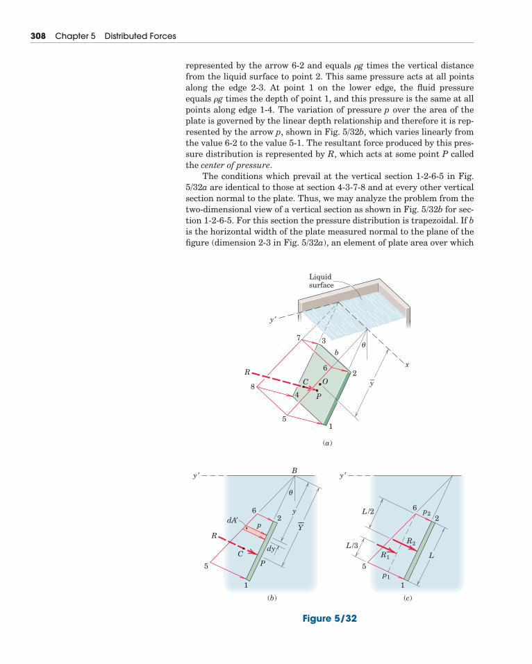
represented by the arrow 6-2 and equals �g times the vertical distancefrom the liquid surface to point 2. This same pressure acts at all pointsalong the edge 2-3. At point 1 on the lower edge, the fluid pressureequals �g times the depth of point 1, and this pressure is the same at allpoints along edge 1-4. The variation of pressure p over the area of theplate is governed by the linear depth relationship and therefore it is rep-resented by the arrow p, shown in Fig. 5/32b, which varies linearly fromthe value 6-2 to the value 5-1. The resultant force produced by this pres-sure distribution is represented by R, which acts at some point P calledthe center of pressure.
The conditions which prevail at the vertical section 1-2-6-5 in Fig.5/32a are identical to those at section 4-3-7-8 and at every other verticalsection normal to the plate. Thus, we may analyze the problem from thetwo-dimensional view of a vertical section as shown in Fig. 5/32b for sec-tion 1-2-6-5. For this section the pressure distribution is trapezoidal. If bis the horizontal width of the plate measured normal to the plane of thefigure (dimension 2-3 in Fig. 5/32a), an element of plate area over which
308 Chapter 5 Distributed Forces
y ′
Liquidsurface
O
bθ
P
B
R
CP
p
y
dy
dA′
CR
8
51
(a)
(b) (c)
2
37
6
4
y–
x
y ′
y ′
θ
2 26
5p1
R1
R2
p2
11
6
5L
L /3
L /2
Y––
Figure 5/32
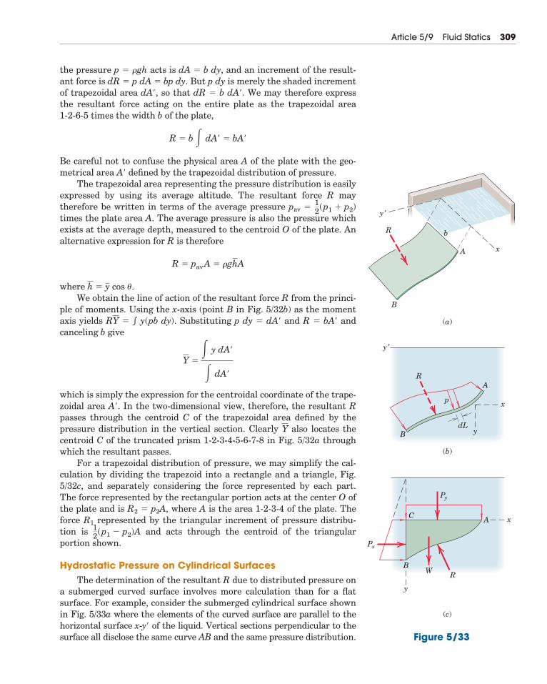
the pressure p � �gh acts is dA � b dy, and an increment of the result-ant force is dR � p dA � bp dy. But p dy is merely the shaded incrementof trapezoidal area dA�, so that dR � b dA�. We may therefore expressthe resultant force acting on the entire plate as the trapezoidal area1-2-6-5 times the width b of the plate,
Be careful not to confuse the physical area A of the plate with the geo-metrical area A� defined by the trapezoidal distribution of pressure.
The trapezoidal area representing the pressure distribution is easilyexpressed by using its average altitude. The resultant force R maytherefore be written in terms of the average pressure pav �
times the plate area A. The average pressure is also the pressure whichexists at the average depth, measured to the centroid O of the plate. Analternative expression for R is therefore
where � cos �.We obtain the line of action of the resultant force R from the princi-
ple of moments. Using the x-axis (point B in Fig. 5/32b) as the momentaxis yields � y(pb dy). Substituting p dy � dA� and R � bA� andcanceling b give
which is simply the expression for the centroidal coordinate of the trape-zoidal area A�. In the two-dimensional view, therefore, the resultant Rpasses through the centroid C of the trapezoidal area defined by thepressure distribution in the vertical section. Clearly also locates thecentroid C of the truncated prism 1-2-3-4-5-6-7-8 in Fig. 5/32a throughwhich the resultant passes.
For a trapezoidal distribution of pressure, we may simplify the cal-culation by dividing the trapezoid into a rectangle and a triangle, Fig.5/32c, and separately considering the force represented by each part.The force represented by the rectangular portion acts at the center O ofthe plate and is R2 � p2A, where A is the area 1-2-3-4 of the plate. Theforce R1 represented by the triangular increment of pressure distribu-tion is and acts through the centroid of the triangular portion shown.
Hydrostatic Pressure on Cylindrical SurfacesThe determination of the resultant R due to distributed pressure on
a submerged curved surface involves more calculation than for a flatsurface. For example, consider the submerged cylindrical surface shownin Fig. 5/33a where the elements of the curved surface are parallel to thehorizontal surface x-y� of the liquid. Vertical sections perpendicular to thesurface all disclose the same curve AB and the same pressure distribution.
12(p1 � p2)A
Y
Y �� y dA�
� dA�
RY
yh
R � pavA � �ghA
12(p1 � p2)
R � b � dA� � bA�
Article 5/9 Fluid Statics 309
dL
R
B
(a)
(b)
B
AR
p
xA
b
y ′
y ′
y
x
R
(c)
BW
AC
Py
Px
y
x
Figure 5/33
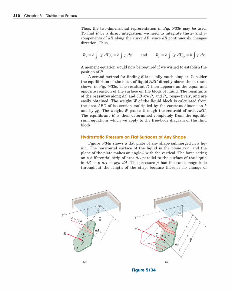
Thus, the two-dimensional representation in Fig. 5/33b may be used. To find R by a direct integration, we need to integrate the x- and y-components of dR along the curve AB, since dR continuously changesdirection. Thus,
A moment equation would now be required if we wished to establish theposition of R.
A second method for finding R is usually much simpler. Considerthe equilibrium of the block of liquid ABC directly above the surface,shown in Fig. 5/33c. The resultant R then appears as the equal andopposite reaction of the surface on the block of liquid. The resultantsof the pressures along AC and CB are Py and Px, respectively, and areeasily obtained. The weight W of the liquid block is calculated fromthe area ABC of its section multiplied by the constant dimension band by �g. The weight W passes through the centroid of area ABC.The equilibrant R is then determined completely from the equilib-rium equations which we apply to the free-body diagram of the fluidblock.
Hydrostatic Pressure on Flat Surfaces of Any ShapeFigure 5/34a shows a flat plate of any shape submerged in a liq-
uid. The horizontal surface of the liquid is the plane x-y�, and theplane of the plate makes an angle � with the vertical. The force actingon a differential strip of area dA parallel to the surface of the liquid is dR � p dA � �gh dA. The pressure p has the same magnitudethroughout the length of the strip, because there is no change of
Rx � b � (p dL)x � b � p dy and Ry � b � (p dL)y � b � p dx
310 Chapter 5 Distributed Forces
y ′
x
y
O
P
(a) (b)
RdA
A
θ
y ′
xy
p
x
O
dyP
C
R
θ
y–
Y––
hp = ghρ h–
Figure 5/34
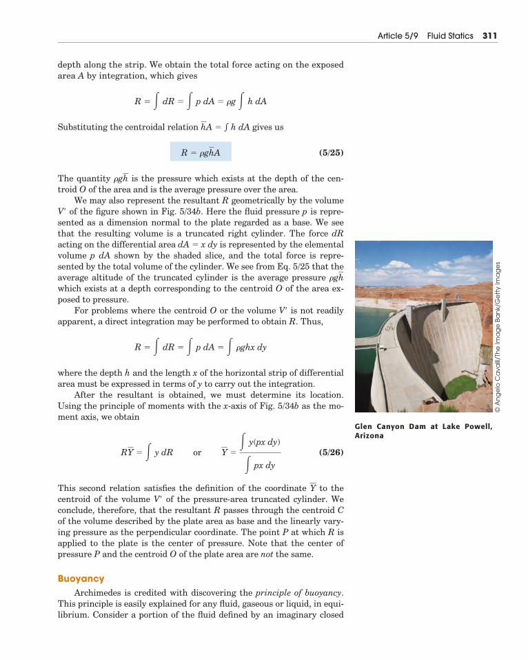
depth along the strip. We obtain the total force acting on the exposedarea A by integration, which gives
Substituting the centroidal relation � gives us
(5/25)
The quantity is the pressure which exists at the depth of the cen-troid O of the area and is the average pressure over the area.
We may also represent the resultant R geometrically by the volumeV� of the figure shown in Fig. 5/34b. Here the fluid pressure p is repre-sented as a dimension normal to the plate regarded as a base. We seethat the resulting volume is a truncated right cylinder. The force dRacting on the differential area dA � x dy is represented by the elementalvolume p dA shown by the shaded slice, and the total force is repre-sented by the total volume of the cylinder. We see from Eq. 5/25 that theaverage altitude of the truncated cylinder is the average pressure which exists at a depth corresponding to the centroid O of the area ex-posed to pressure.
For problems where the centroid O or the volume V� is not readilyapparent, a direct integration may be performed to obtain R. Thus,
where the depth h and the length x of the horizontal strip of differentialarea must be expressed in terms of y to carry out the integration.
After the resultant is obtained, we must determine its location.Using the principle of moments with the x-axis of Fig. 5/34b as the mo-ment axis, we obtain
(5/26)
This second relation satisfies the definition of the coordinate to thecentroid of the volume V� of the pressure-area truncated cylinder. Weconclude, therefore, that the resultant R passes through the centroid Cof the volume described by the plate area as base and the linearly vary-ing pressure as the perpendicular coordinate. The point P at which R isapplied to the plate is the center of pressure. Note that the center ofpressure P and the centroid O of the plate area are not the same.
BuoyancyArchimedes is credited with discovering the principle of buoyancy.
This principle is easily explained for any fluid, gaseous or liquid, in equi-librium. Consider a portion of the fluid defined by an imaginary closed
Y
RY � � y dR or Y �� y(px dy)
� px dy
R � � dR � � p dA � � �ghx dy
�gh
�gh
R � �ghA
h dAhA
R � � dR � � p dA � �g � h dA
Article 5/9 Fluid Statics 311
Glen Canyon Dam at Lake Powell,Arizona
© A
ng
elo
Ca
valli
/Th
e Im
ag
e B
an
k/G
ett
y Im
ag
es
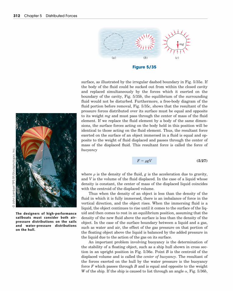
surface, as illustrated by the irregular dashed boundary in Fig. 5/35a. Ifthe body of the fluid could be sucked out from within the closed cavityand replaced simultaneously by the forces which it exerted on theboundary of the cavity, Fig. 5/35b, the equilibrium of the surroundingfluid would not be disturbed. Furthermore, a free-body diagram of thefluid portion before removal, Fig. 5/35c, shows that the resultant of thepressure forces distributed over its surface must be equal and oppositeto its weight mg and must pass through the center of mass of the fluidelement. If we replace the fluid element by a body of the same dimen-sions, the surface forces acting on the body held in this position will beidentical to those acting on the fluid element. Thus, the resultant forceexerted on the surface of an object immersed in a fluid is equal and op-posite to the weight of fluid displaced and passes through the center ofmass of the displaced fluid. This resultant force is called the force ofbuoyancy
(5/27)
where � is the density of the fluid, g is the acceleration due to gravity,and V is the volume of the fluid displaced. In the case of a liquid whosedensity is constant, the center of mass of the displaced liquid coincideswith the centroid of the displaced volume.
Thus when the density of an object is less than the density of thefluid in which it is fully immersed, there is an imbalance of force in thevertical direction, and the object rises. When the immersing fluid is aliquid, the object continues to rise until it comes to the surface of the liq-uid and then comes to rest in an equilibrium position, assuming that thedensity of the new fluid above the surface is less than the density of theobject. In the case of the surface boundary between a liquid and a gas,such as water and air, the effect of the gas pressure on that portion ofthe floating object above the liquid is balanced by the added pressure inthe liquid due to the action of the gas on its surface.
An important problem involving buoyancy is the determination ofthe stability of a floating object, such as a ship hull shown in cross sec-tion in an upright position in Fig. 5/36a. Point B is the centroid of thedisplaced volume and is called the center of buoyancy. The resultant ofthe forces exerted on the hull by the water pressure is the buoyancyforce F which passes through B and is equal and opposite to the weightW of the ship. If the ship is caused to list through an angle �, Fig. 5/36b,
F � �gV
312 Chapter 5 Distributed Forces
The designers of high-performancesailboats must consider both air-pressure distributions on the sailsand water-pressure distributionson the hull.
© J
oh
n L
am
be
rt T
IPS
RF/
Sto
ckp
ho
top
ro, I
nc
.
(a) (b) (c)
mg
Figure 5/35
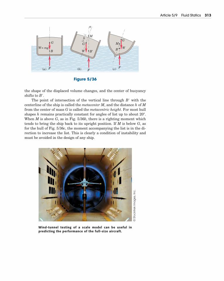
Article 5/9 Fluid Statics 313
Wind-tunnel testing of a scale model can be useful inpredicting the performance of the full-size aircraft.
© S
toc
ktre
k Im
ag
es,
Inc
.
F
G
BW = mg
GG
M
M
α
h
WW B′B′
FF(a) (b) (c)
Figure 5/36
the shape of the displaced volume changes, and the center of buoyancyshifts to B�.
The point of intersection of the vertical line through B� with thecenterline of the ship is called the metacenter M, and the distance h of Mfrom the center of mass G is called the metacentric height. For most hullshapes h remains practically constant for angles of list up to about 20�.When M is above G, as in Fig. 5/36b, there is a righting moment whichtends to bring the ship back to its upright position. If M is below G, asfor the hull of Fig. 5/36c, the moment accompanying the list is in the di-rection to increase the list. This is clearly a condition of instability andmust be avoided in the design of any ship.
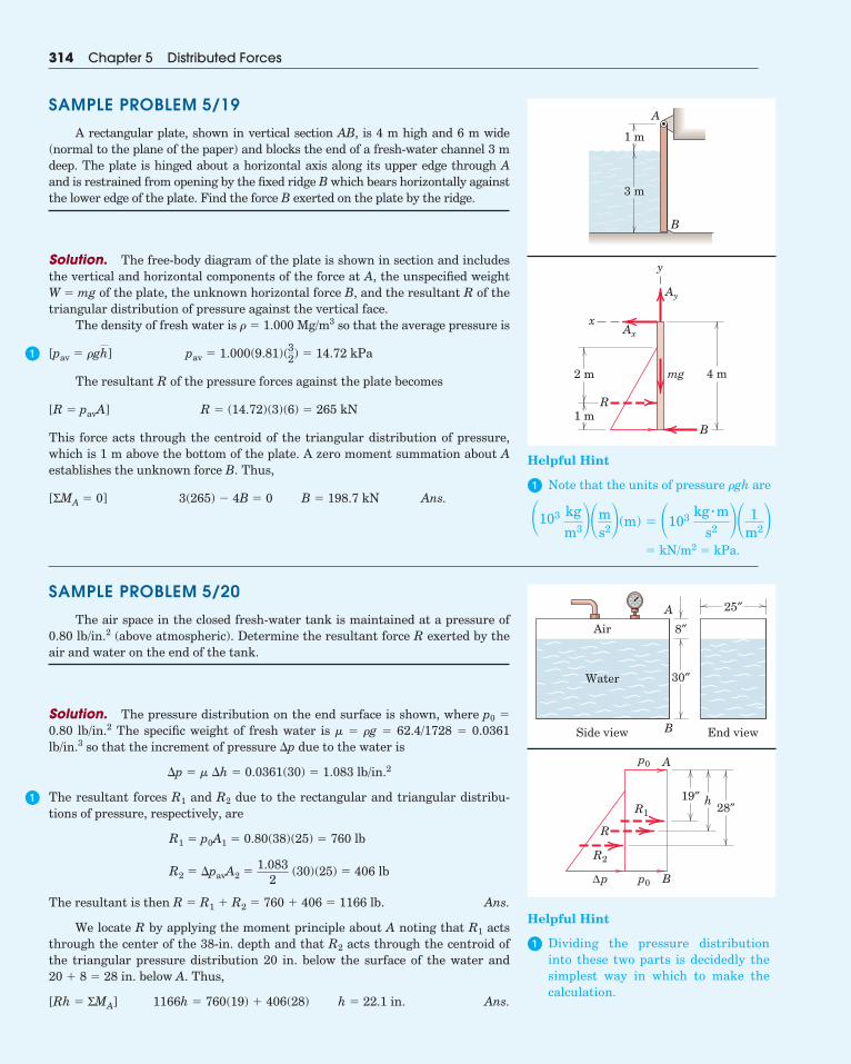
314 Chapter 5 Distributed Forces
SAMPLE PROBLEM 5/19
A rectangular plate, shown in vertical section AB, is 4 m high and 6 m wide(normal to the plane of the paper) and blocks the end of a fresh-water channel 3 mdeep. The plate is hinged about a horizontal axis along its upper edge through Aand is restrained from opening by the fixed ridge B which bears horizontally againstthe lower edge of the plate. Find the force B exerted on the plate by the ridge.
Solution. The free-body diagram of the plate is shown in section and includesthe vertical and horizontal components of the force at A, the unspecified weightW � mg of the plate, the unknown horizontal force B, and the resultant R of thetriangular distribution of pressure against the vertical face.
The density of fresh water is � � 1.000 Mg/m3 so that the average pressure is
The resultant R of the pressure forces against the plate becomes
This force acts through the centroid of the triangular distribution of pressure,which is 1 m above the bottom of the plate. A zero moment summation about Aestablishes the unknown force B. Thus,
Ans.3(265) � 4B � 0 B � 198.7 kN[ΣMA � 0]
R � (14.72)(3)(6) � 265 kN[R � pavA]
pav � 1.000(9.81)(32) � 14.72 kPa[pav � �gh]
SAMPLE PROBLEM 5/20
The air space in the closed fresh-water tank is maintained at a pressure of0.80 lb/in.2 (above atmospheric). Determine the resultant force R exerted by theair and water on the end of the tank.
Solution. The pressure distribution on the end surface is shown, where p0 �
0.80 lb/in.2 The specific weight of fresh water is � � �g � 62.4/1728 � 0.0361lb/in.3 so that the increment of pressure �p due to the water is
The resultant forces R1 and R2 due to the rectangular and triangular distribu-tions of pressure, respectively, are
Ans.
We locate R by applying the moment principle about A noting that R1 actsthrough the center of the 38-in. depth and that R2 acts through the centroid ofthe triangular pressure distribution 20 in. below the surface of the water and 20 � 8 � 28 in. below A. Thus,
Ans.1166h � 760(19) � 406(28) h � 22.1 in.[Rh � ΣMA]
The resultant is then R � R1 � R2 � 760 � 406 � 1166 lb.
R2 � �pavA2 �1.083
2 (30)(25) � 406 lb
R1 � p0A1 � 0.80(38)(25) � 760 lb
�p � � �h � 0.0361(30) � 1.083 lb/in.2
1 m
B
A
3 m
Ay
y
2 m
R
mg 4 m
Axx
B1 m
Side view
Air
Water
B
A 25″
8″
30″
End view
Bp0
p0
R1
R2
R
Δp
A
19″ h28″
Helpful Hint
� Dividing the pressure distributioninto these two parts is decidedly thesimplest way in which to make thecalculation.
�
�
Helpful Hint
� Note that the units of pressure �gh are
� kN/m2 � kPa.
�103 kgm3�m
s2(m) � �103 kg � ms2 � 1
m2
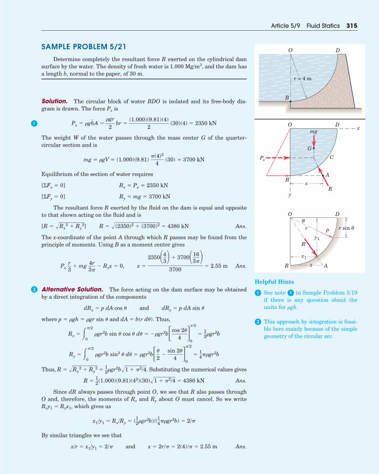
SAMPLE PROBLEM 5/21
Determine completely the resultant force R exerted on the cylindrical damsurface by the water. The density of fresh water is 1.000 Mg/m3, and the dam hasa length b, normal to the paper, of 30 m.
Solution. The circular block of water BDO is isolated and its free-body dia-gram is drawn. The force Px is
The weight W of the water passes through the mass center G of the quarter-circular section and is
Equilibrium of the section of water requires
The resultant force R exerted by the fluid on the dam is equal and oppositeto that shown acting on the fluid and is
Ans.
The x-coordinate of the point A through which R passes may be found from theprinciple of moments. Using B as a moment center gives
Ans.
Alternative Solution. The force acting on the dam surface may be obtainedby a direct integration of the components
where p � �gh � �gr sin � and dA � b(r d�). Thus,
Thus, R � � Substituting the numerical values gives
Ans.
Since dR always passes through point O, we see that R also passes throughO and, therefore, the moments of Rx and Ry about O must cancel. So we writeRxy1 � Ryx1, which gives us
By similar triangles we see that
Ans.x/r � x1/y1 � 2/� and x � 2r/� � 2(4)/� � 2.55 m
x1/y1 � Rx/Ry � (12�gr2b)/(14��gr2b) � 2/�
R �12(1.000)(9.81)(42)(30)�1 � �2/4 � 4380 kN
12�gr2b�1 � �2/4.�Rx
2 � Ry
2
Ry � ��/2
0�gr2b sin2 � d� � �gr2b��
2�
sin 2�
4 ��/2
0
�14��gr2b
Rx � ��/2
0�gr2b sin � cos � d� � ��gr2b�cos 2�
4 ��/2
0
�12�gr2b
dRx � p dA cos � and dRy � p dA sin �
Pxr3
� mg 4r3�
� Ryx � 0, x �
2350�43 � 3700�16
3�3700
� 2.55 m
R � �(2350)2 � (3700)2 � 4380 kN[R � �Rx
2 � Ry
2]
Ry � mg � 3700 kN[ΣFy � 0]
Rx � Px � 2350 kN[ΣFx � 0]
mg � �gV � (1.000)(9.81) �(4)2
4 (30) � 3700 kN
Px � �ghA ��gr2
br �(1.000)(9.81)(4)
2 (30)(4) � 2350 kN
Article 5/9 Fluid Statics 315
r = 4 m
B
O D
x
y
x
D
G
C
A
R
B
Px
Omg
x
D
r p
θr sin θ
A
R
B
x1
y1
O
�
�Helpful Hints
� See note � in Sample Problem 5/19if there is any question about theunits for
� This approach by integration is feasi-ble here mainly because of the simplegeometry of the circular arc.
�gh.
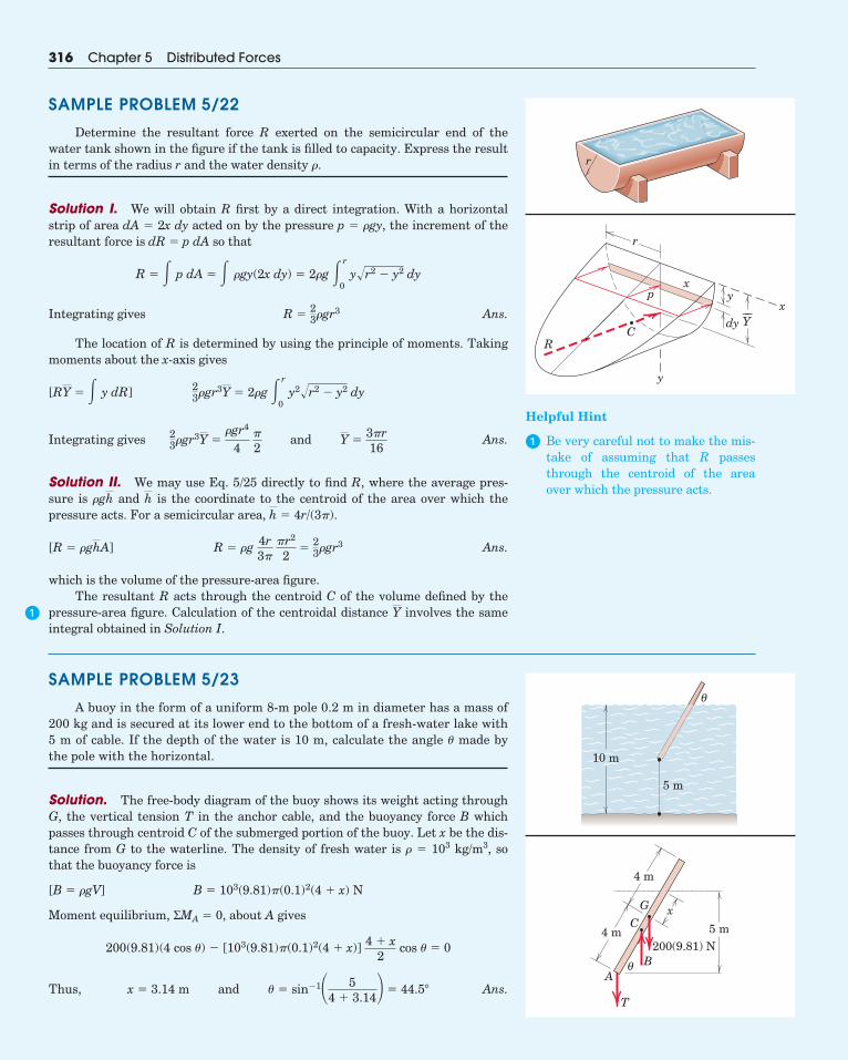
SAMPLE PROBLEM 5/22
Determine the resultant force R exerted on the semicircular end of thewater tank shown in the figure if the tank is filled to capacity. Express the resultin terms of the radius r and the water density �.
Solution I. We will obtain R first by a direct integration. With a horizontalstrip of area dA � 2x dy acted on by the pressure p � �gy, the increment of theresultant force is dR � p dA so that
Integrating gives Ans.
The location of R is determined by using the principle of moments. Takingmoments about the x-axis gives
Integrating gives Ans.
Solution II. We may use Eq. 5/25 directly to find R, where the average pres-sure is and is the coordinate to the centroid of the area over which thepressure acts. For a semicircular area, � 4r/(3�).
Ans.
which is the volume of the pressure-area figure.The resultant R acts through the centroid C of the volume defined by the
pressure-area figure. Calculation of the centroidal distance involves the sameintegral obtained in Solution I.
Y
R � �g 4r3�
�r2
2�
23�gr3[R � �ghA]
hh�gh
23�gr3Y �
�gr4
4�2
and Y �3�r16
23�gr3Y � 2�g � r
0y2�r2 � y2 dy[RY � � y dR]
R �23�gr3
R � � p dA � � �gy(2x dy) � 2�g � r
0y�r2 � y2 dy
316 Chapter 5 Distributed Forces
SAMPLE PROBLEM 5/23
A buoy in the form of a uniform 8-m pole 0.2 m in diameter has a mass of200 kg and is secured at its lower end to the bottom of a fresh-water lake with5 m of cable. If the depth of the water is 10 m, calculate the angle � made bythe pole with the horizontal.
Solution. The free-body diagram of the buoy shows its weight acting throughG, the vertical tension T in the anchor cable, and the buoyancy force B whichpasses through centroid C of the submerged portion of the buoy. Let x be the dis-tance from G to the waterline. The density of fresh water is � � 103 kg/m3, sothat the buoyancy force is
Moment equilibrium, ΣMA � 0, about A gives
Thus, Ans.x � 3.14 m and � � sin�1� 54 � 3.14 � 44.5�
200(9.81)(4 cos �) � [103(9.81)�(0.1)2(4 � x)] 4 � x2
cos � � 0
B � 103(9.81)�(0.1)2(4 � x) N[B � �gV]
r
y
xy
dy
x
r
p
CR
Y––
�
Helpful Hint
� Be very careful not to make the mis-take of assuming that R passesthrough the centroid of the areaover which the pressure acts.
θ
10 m
5 m
x
4 m
AB
T
4 m
C
G
5 m200(9.81) N
θ
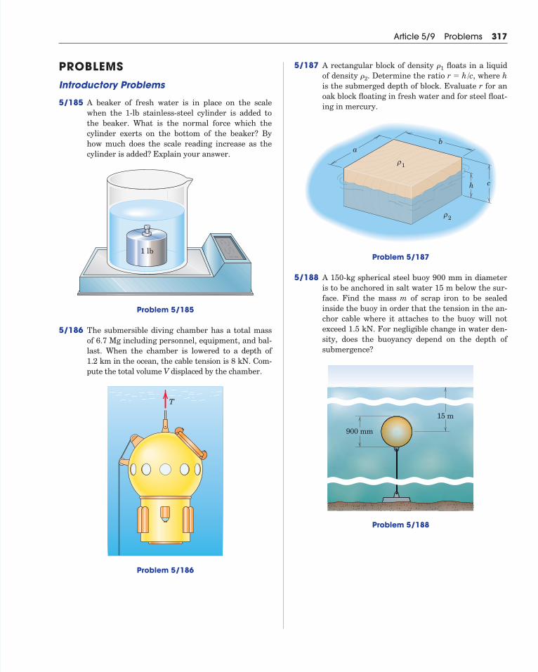
PROBLEMSIntroductory Problems
5/185 A beaker of fresh water is in place on the scalewhen the 1-lb stainless-steel cylinder is added tothe beaker. What is the normal force which thecylinder exerts on the bottom of the beaker? Byhow much does the scale reading increase as thecylinder is added? Explain your answer.
Problem 5/185
5/186 The submersible diving chamber has a total massof 6.7 Mg including personnel, equipment, and bal-last. When the chamber is lowered to a depth of 1.2 km in the ocean, the cable tension is 8 kN. Com-pute the total volume V displaced by the chamber.
Problem 5/186
T
1 lb
Article 5/9 Problems 317
5/187 A rectangular block of density floats in a liquidof density . Determine the ratio , where his the submerged depth of block. Evaluate r for anoak block floating in fresh water and for steel float-ing in mercury.
Problem 5/187
5/188 A 150-kg spherical steel buoy 900 mm in diameteris to be anchored in salt water 15 m below the sur-face. Find the mass m of scrap iron to be sealed inside the buoy in order that the tension in the an-chor cable where it attaches to the buoy will notexceed 1.5 kN. For negligible change in water den-sity, does the buoyancy depend on the depth ofsubmergence?
Problem 5/188
900 mm
15 m
ab
ρ1
ρ2
ch
r � h/c�2
�1
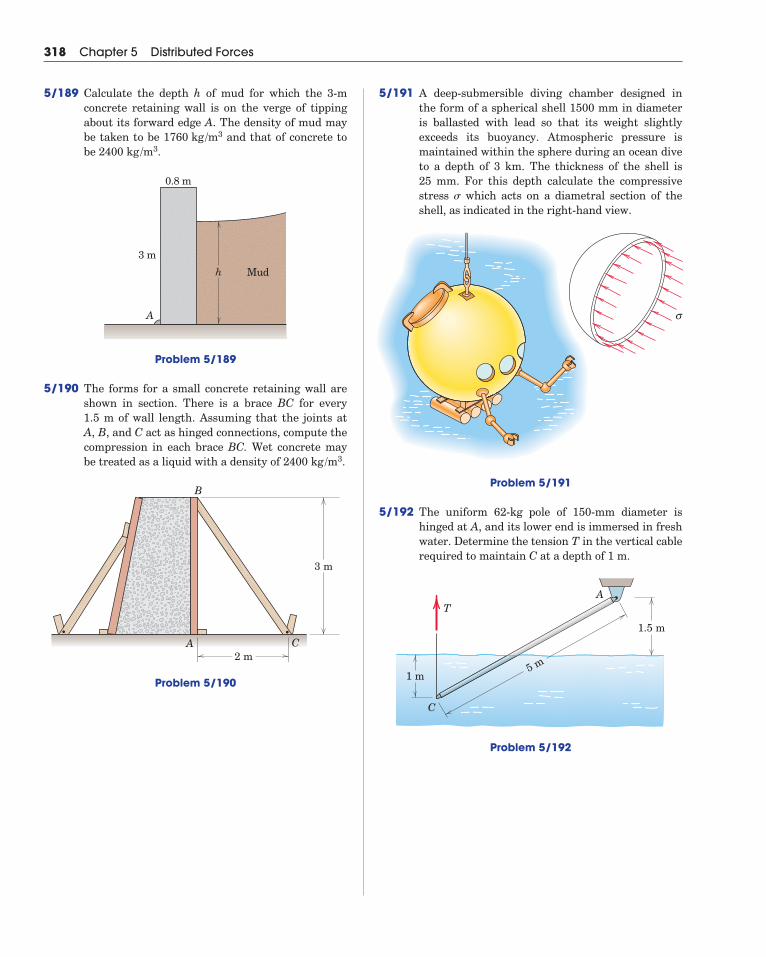
5/191 A deep-submersible diving chamber designed inthe form of a spherical shell 1500 mm in diameteris ballasted with lead so that its weight slightly exceeds its buoyancy. Atmospheric pressure ismaintained within the sphere during an ocean diveto a depth of 3 km. The thickness of the shell is 25 mm. For this depth calculate the compressivestress which acts on a diametral section of theshell, as indicated in the right-hand view.
Problem 5/191
5/192 The uniform 62-kg pole of 150-mm diameter ishinged at A, and its lower end is immersed in freshwater. Determine the tension T in the vertical cablerequired to maintain C at a depth of 1 m.
Problem 5/192
5 m1 m
1.5 m
C
AT
σ
318 Chapter 5 Distributed Forces
5/189 Calculate the depth h of mud for which the 3-mconcrete retaining wall is on the verge of tippingabout its forward edge A. The density of mud maybe taken to be and that of concrete tobe .
Problem 5/189
5/190 The forms for a small concrete retaining wall areshown in section. There is a brace BC for every 1.5 m of wall length. Assuming that the joints atA, B, and C act as hinged connections, compute thecompression in each brace BC. Wet concrete maybe treated as a liquid with a density of .
Problem 5/190
3 m
2 mA
B
C
2400 kg /m3
h Mud
3 m
0.8 m
A
2400 kg /m31760 kg /m3
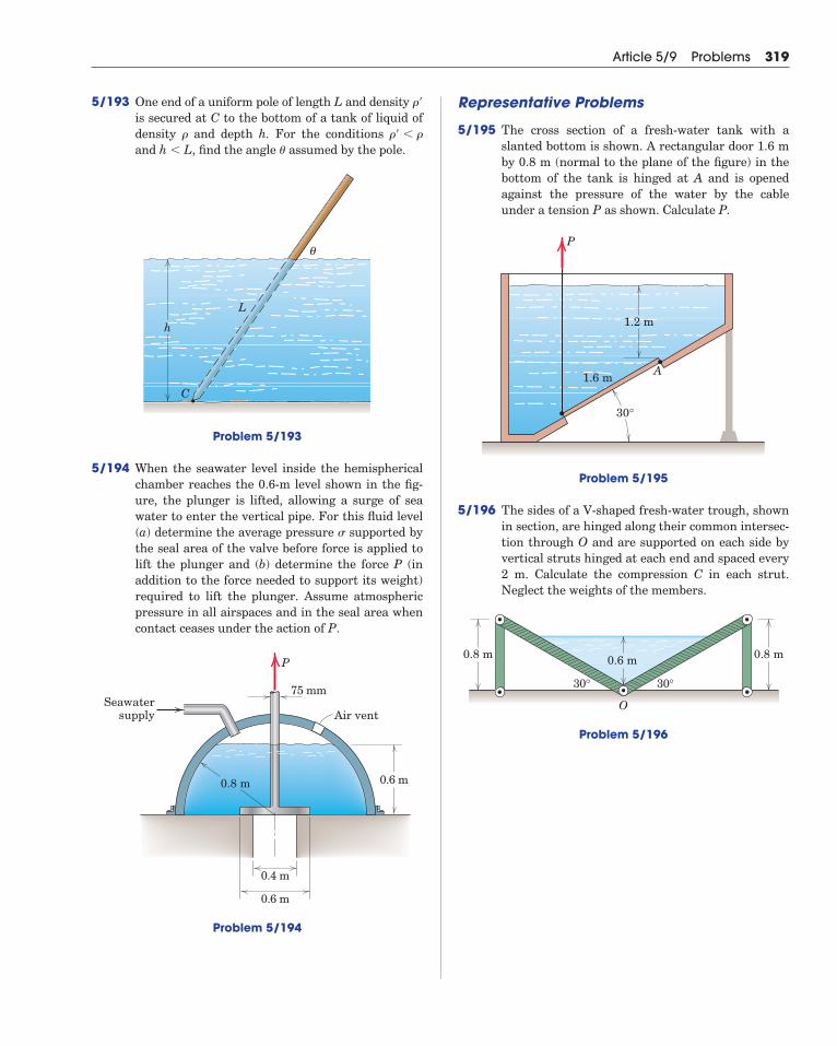
5/193 One end of a uniform pole of length L and density is secured at C to the bottom of a tank of liquid ofdensity and depth h. For the conditions and , find the angle assumed by the pole.
Problem 5/193
5/194 When the seawater level inside the hemisphericalchamber reaches the 0.6-m level shown in the fig-ure, the plunger is lifted, allowing a surge of seawater to enter the vertical pipe. For this fluid level(a) determine the average pressure supported bythe seal area of the valve before force is applied tolift the plunger and (b) determine the force P (inaddition to the force needed to support its weight)required to lift the plunger. Assume atmosphericpressure in all airspaces and in the seal area whencontact ceases under the action of P.
Problem 5/194
Seawatersupply Air vent
P
0.8 m
75 mm
0.4 m
0.6 m
0.6 m
C
L
θ
h
�h � L�� � ��
��
Article 5/9 Problems 319
Representative Problems
5/195 The cross section of a fresh-water tank with aslanted bottom is shown. A rectangular door 1.6 mby 0.8 m (normal to the plane of the figure) in thebottom of the tank is hinged at A and is openedagainst the pressure of the water by the cableunder a tension P as shown. Calculate P.
Problem 5/195
5/196 The sides of a V-shaped fresh-water trough, shownin section, are hinged along their common intersec-tion through O and are supported on each side byvertical struts hinged at each end and spaced every2 m. Calculate the compression C in each strut. Neglect the weights of the members.
Problem 5/196
0.8 m 0.6 m
30° 30°
O
0.8 m
P
1.2 m
1.6 m A
30°
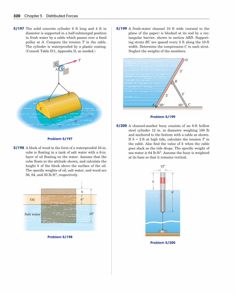
5/199 A fresh-water channel 10 ft wide (normal to theplane of the paper) is blocked at its end by a rec-tangular barrier, shown in section ABD. Support-ing struts BC are spaced every 2 ft along the 10-ftwidth. Determine the compression C in each strut.Neglect the weights of the members.
Problem 5/199
5/200 A channel-marker buoy consists of an 8-ft hollowsteel cylinder 12 in. in diameter weighing 180 lband anchored to the bottom with a cable as shown.If at high tide, calculate the tension T inthe cable. Also find the value of h when the cablegoes slack as the tide drops. The specific weight ofsea water is . Assume the buoy is weightedat its base so that it remains vertical.
Problem 5/200
12″
8′
h
64 lb /ft3
h � 2 ft
2′
2′
2′
A
B
C
D
60° 60°
320 Chapter 5 Distributed Forces
5/197 The solid concrete cylinder 6 ft long and 4 ft in diameter is supported in a half-submerged positionin fresh water by a cable which passes over a fixedpulley at A. Compute the tension T in the cable.The cylinder is waterproofed by a plastic coating.(Consult Table D/1, Appendix D, as needed.)
Problem 5/197
5/198 A block of wood in the form of a waterproofed 16-in.cube is floating in a tank of salt water with a 6-in.layer of oil floating on the water. Assume that thecube floats in the attitude shown, and calculate theheight h of the block above the surface of the oil.The specific weights of oil, salt water, and wood are56, 64, and , respectively.
Problem 5/198
Oil
Salt water
h
6″
16″
50 lb /ft3
A
T
6′
2′
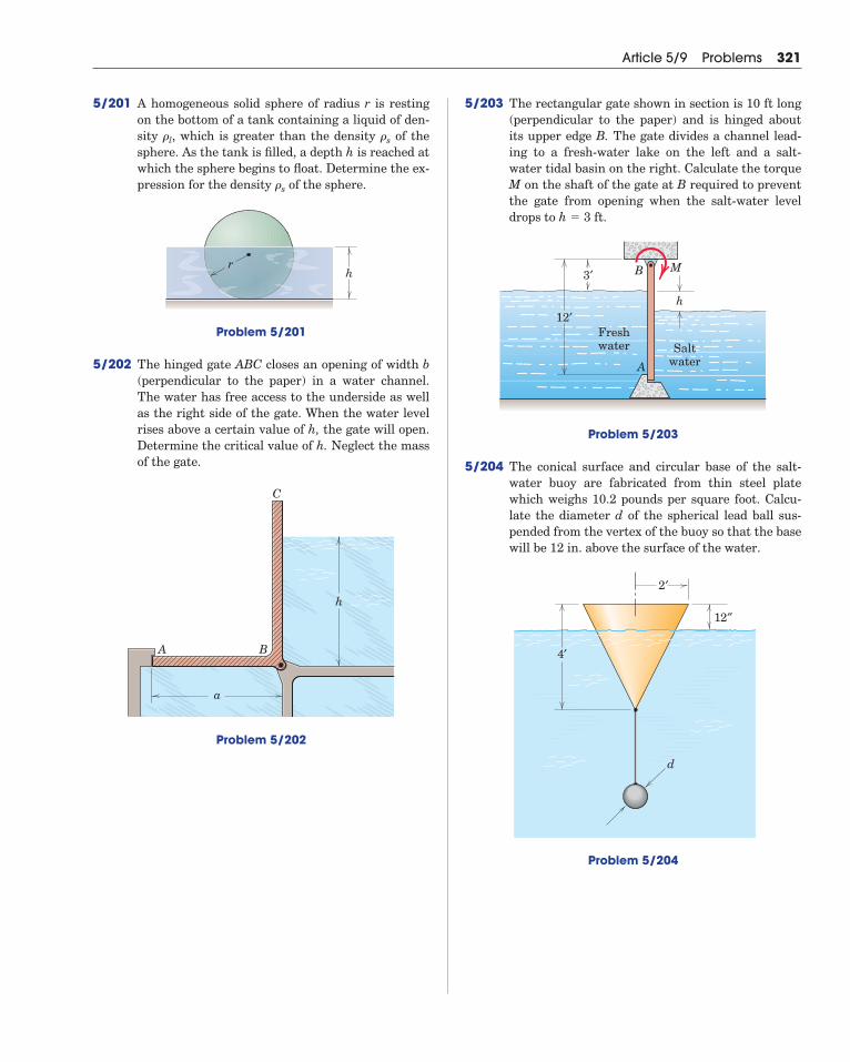
5/201 A homogeneous solid sphere of radius r is restingon the bottom of a tank containing a liquid of den-sity , which is greater than the density of thesphere. As the tank is filled, a depth h is reached atwhich the sphere begins to float. Determine the ex-pression for the density of the sphere.
Problem 5/201
5/202 The hinged gate ABC closes an opening of width b(perpendicular to the paper) in a water channel.The water has free access to the underside as wellas the right side of the gate. When the water levelrises above a certain value of h, the gate will open.Determine the critical value of h. Neglect the massof the gate.
Problem 5/202
a
h
C
A B
hr
�s
�s�l
Article 5/9 Problems 321
5/203 The rectangular gate shown in section is 10 ft long(perpendicular to the paper) and is hinged aboutits upper edge B. The gate divides a channel lead-ing to a fresh-water lake on the left and a salt-water tidal basin on the right. Calculate the torqueM on the shaft of the gate at B required to preventthe gate from opening when the salt-water leveldrops to .
Problem 5/203
5/204 The conical surface and circular base of the salt-water buoy are fabricated from thin steel platewhich weighs 10.2 pounds per square foot. Calcu-late the diameter d of the spherical lead ball sus-pended from the vertex of the buoy so that the basewill be 12 in. above the surface of the water.
Problem 5/204
4′
d
12″
2′
12′
3′ B M
A
h
Saltwater
Freshwater
h � 3 ft
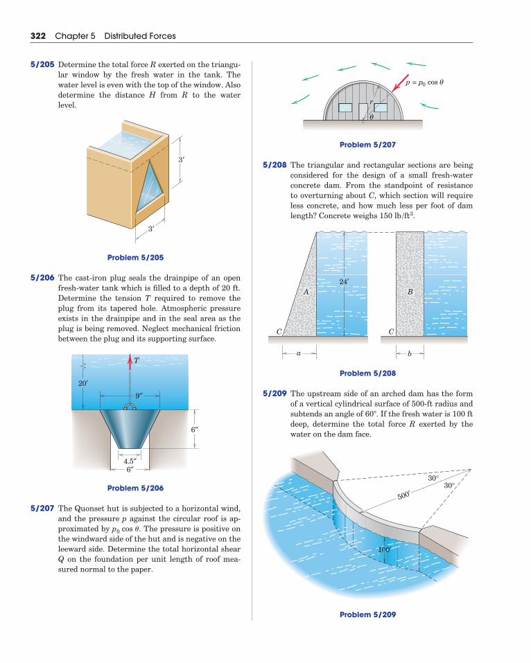
Problem 5/207
5/208 The triangular and rectangular sections are beingconsidered for the design of a small fresh-waterconcrete dam. From the standpoint of resistance to overturning about C, which section will requireless concrete, and how much less per foot of damlength? Concrete weighs .
Problem 5/208
5/209 The upstream side of an arched dam has the formof a vertical cylindrical surface of 500-ft radius andsubtends an angle of . If the fresh water is 100 ftdeep, determine the total force R exerted by thewater on the dam face.
Problem 5/209
60�
ba
C C
A B24′
150 lb /ft3
θ
r
θp = p0 cos
500′30°
30°
100′
322 Chapter 5 Distributed Forces
5/205 Determine the total force R exerted on the triangu-lar window by the fresh water in the tank. Thewater level is even with the top of the window. Alsodetermine the distance H from R to the waterlevel.
Problem 5/205
5/206 The cast-iron plug seals the drainpipe of an openfresh-water tank which is filled to a depth of 20 ft.Determine the tension T required to remove theplug from its tapered hole. Atmospheric pressureexists in the drainpipe and in the seal area as theplug is being removed. Neglect mechanical frictionbetween the plug and its supporting surface.
Problem 5/206
5/207 The Quonset hut is subjected to a horizontal wind,and the pressure p against the circular roof is ap-proximated by . The pressure is positive onthe windward side of the hut and is negative on theleeward side. Determine the total horizontal shearQ on the foundation per unit length of roof mea-sured normal to the paper.
p0 cos �
T
9″
6″4.5″
6″
20′
3′
3′
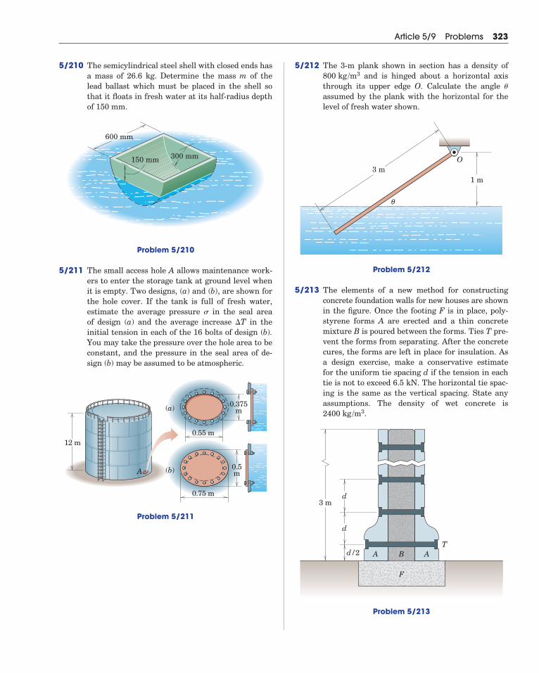
5/210 The semicylindrical steel shell with closed ends hasa mass of 26.6 kg. Determine the mass m of thelead ballast which must be placed in the shell sothat it floats in fresh water at its half-radius depthof 150 mm.
Problem 5/210
5/211 The small access hole A allows maintenance work-ers to enter the storage tank at ground level whenit is empty. Two designs, (a) and (b), are shown forthe hole cover. If the tank is full of fresh water, estimate the average pressure in the seal area of design (a) and the average increase in theinitial tension in each of the 16 bolts of design (b).You may take the pressure over the hole area to beconstant, and the pressure in the seal area of de-sign (b) may be assumed to be atmospheric.
Problem 5/211
0.375m
0.5m
12 m0.55 m
0.75 m
(b)A
(a)
�T
600 mm
300 mm150 mm
Article 5/9 Problems 323
5/212 The 3-m plank shown in section has a density ofand is hinged about a horizontal axis
through its upper edge O. Calculate the angle assumed by the plank with the horizontal for thelevel of fresh water shown.
Problem 5/212
5/213 The elements of a new method for constructingconcrete foundation walls for new houses are shownin the figure. Once the footing F is in place, poly-styrene forms A are erected and a thin concretemixture B is poured between the forms. Ties T pre-vent the forms from separating. After the concretecures, the forms are left in place for insulation. Asa design exercise, make a conservative estimate for the uniform tie spacing d if the tension in eachtie is not to exceed 6.5 kN. The horizontal tie spac-ing is the same as the vertical spacing. State anyassumptions. The density of wet concrete is
.
Problem 5/213
d
d
d/2 A AT
B
F
3 m
2400 kg /m3
3 m1 m
O
θ
�
800 kg /m3
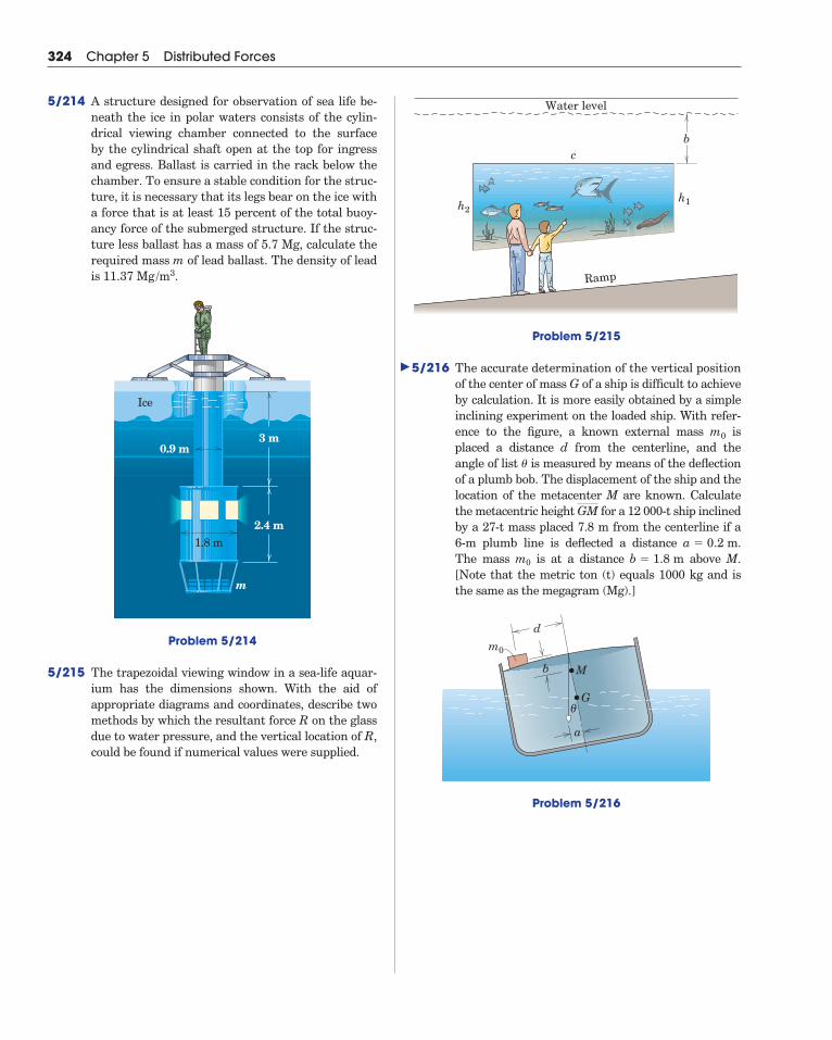
Problem 5/215
5/216 The accurate determination of the vertical positionof the center of mass G of a ship is difficult to achieveby calculation. It is more easily obtained by a simpleinclining experiment on the loaded ship. With refer-ence to the figure, a known external mass isplaced a distance d from the centerline, and theangle of list is measured by means of the deflectionof a plumb bob. The displacement of the ship and thelocation of the metacenter M are known. Calculatethe metacentric height for a 12 000-t ship inclinedby a 27-t mass placed 7.8 m from the centerline if a6-m plumb line is deflected a distance .The mass m0 is at a distance above M.[Note that the metric ton (t) equals 1000 kg and isthe same as the megagram (Mg).]
Problem 5/216
b
a
θ
d
m0
M
G
b � 1.8 ma � 0.2 m
GM
�
m0
bc
Ramp
h1h2
Water level
324 Chapter 5 Distributed Forces
5/214 A structure designed for observation of sea life be-neath the ice in polar waters consists of the cylin-drical viewing chamber connected to the surface by the cylindrical shaft open at the top for ingressand egress. Ballast is carried in the rack below thechamber. To ensure a stable condition for the struc-ture, it is necessary that its legs bear on the ice witha force that is at least 15 percent of the total buoy-ancy force of the submerged structure. If the struc-ture less ballast has a mass of 5.7 Mg, calculate therequired mass m of lead ballast. The density of leadis .
Problem 5/214
5/215 The trapezoidal viewing window in a sea-life aquar-ium has the dimensions shown. With the aid of appropriate diagrams and coordinates, describe twomethods by which the resultant force R on the glassdue to water pressure, and the vertical location of R,could be found if numerical values were supplied.
2.4 m
0.9 m
1.8 m
Ice
m
3 m
11.37 Mg /m3
�
5/10 Chapter ReviewIn Chapter 5 we have studied various common examples of forces
distributed throughout volumes, over areas, and along lines. In all theseproblems we often need to determine the resultant of the distributedforces and the location of the resultant.
Finding Resultants of Distributed ForcesTo find the resultant and line of action of a distributed force:
1. Begin by multiplying the intensity of the force by the appropriateelement of volume, area, or length in terms of which the intensity isexpressed. Then sum (integrate) the incremental forces over the re-gion involved to obtain their resultant.
2. To locate the line of action of the resultant, use the principle of mo-ments. Evaluate the sum of the moments, about a convenient axis,of all of the increments of force. Equate this sum to the moment ofthe resultant about the same axis. Then solve for the unknown mo-ment arm of the resultant.
Gravitational ForcesWhen force is distributed throughout a mass, as in the case of gravi-
tational attraction, the intensity is the force of attraction �g per unit ofvolume, where � is the density and g is the gravitational acceleration.For bodies whose density is constant, we saw in Section A that �g can-cels when the moment principle is applied. This leaves us with a strictlygeometric problem of finding the centroid of the figure, which coincideswith the mass center of the physical body whose boundary defines thefigure.
1. For flat plates and shells which are homogeneous and have constantthickness, the problem becomes one of finding the properties of anarea.
2. For slender rods and wires of uniform density and constant crosssection, the problem becomes one of finding the properties of a linesegment.
Integration of Differential RelationshipsFor problems which require the integration of differential relation-
ships, keep in mind the following considerations.
1. Select a coordinate system which provides the simplest descriptionof the boundaries of the region of integration.
2. Eliminate higher-order differential quantities whenever lower-order differential quantities will remain.
3. Choose a first-order differential element in preference to a second-order element and a second-order element in preference to a third-order element.
Article 5/10 Chapter Review 325

4. Whenever possible, choose a differential element which avoids dis-continuities within the region of integration.
Distributed Forces in Beams, Cables, and FluidsIn Section B we used these guidelines along with the principles of
equilibrium to solve for the effects of distributed forces in beams, cables,and fluids. Remember that:
1. For beams and cables the force intensity is expressed as force perunit length.
2. For fluids the force intensity is expressed as force per unit area, orpressure.
Although beams, cables, and fluids are physically quite different applica-tions, their problem formulations share the common elements citedabove.
326 Chapter 5 Distributed Forces
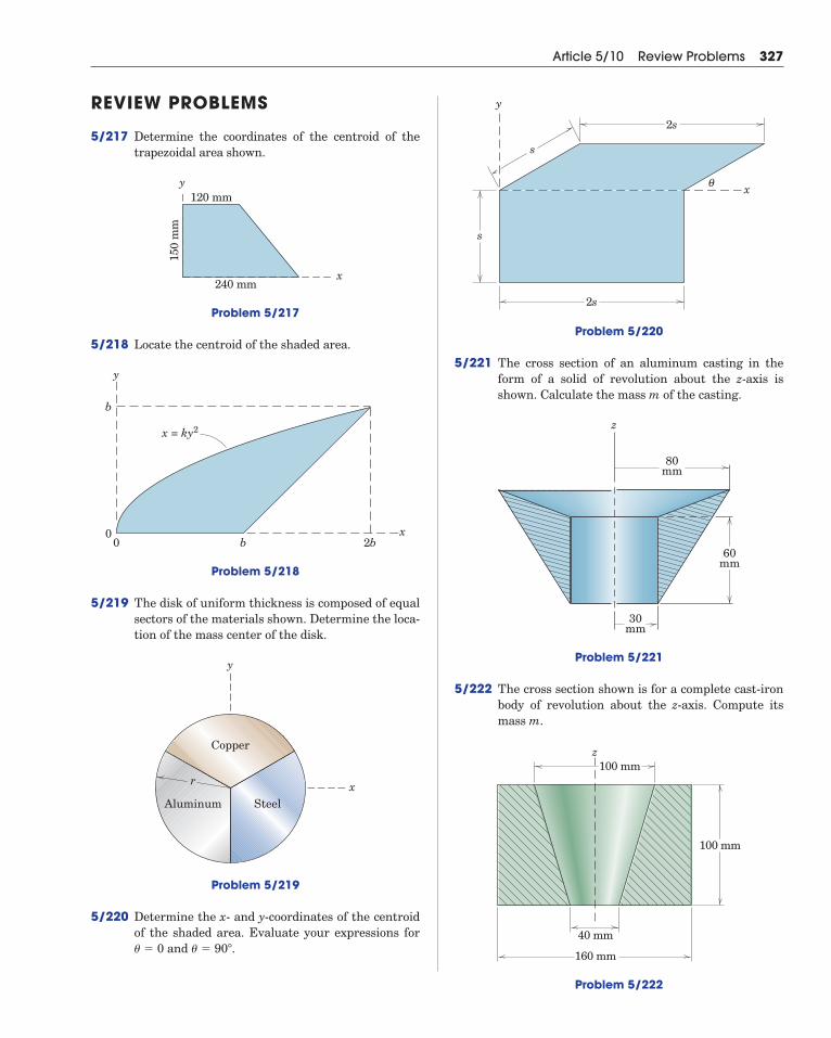
REVIEW PROBLEMS
5/217 Determine the coordinates of the centroid of thetrapezoidal area shown.
Problem 5/217
5/218 Locate the centroid of the shaded area.
Problem 5/218
5/219 The disk of uniform thickness is composed of equalsectors of the materials shown. Determine the loca-tion of the mass center of the disk.
Problem 5/219
5/220 Determine the x- and y-coordinates of the centroidof the shaded area. Evaluate your expressions for
and .� � 90�� � 0
r
y
xAluminum Steel
Copper
0
b
0 b 2b
x = ky2
x
y
x240 mm
120 mmy
150
mm
Article 5/10 Review Problems 327
Problem 5/220
5/221 The cross section of an aluminum casting in theform of a solid of revolution about the z-axis isshown. Calculate the mass m of the casting.
Problem 5/221
5/222 The cross section shown is for a complete cast-ironbody of revolution about the z-axis. Compute itsmass m.
Problem 5/222
100 mm
40 mm
100 mm
160 mm
z
30mm
80mm
60mm
z
2s
θ
s
s
2s
x
y
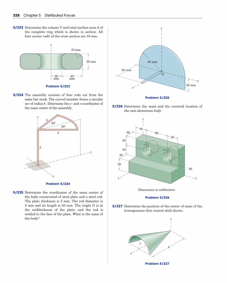
Problem 5/225
5/226 Determine the mass and the centroid location ofthe cast-aluminum body.
Problem 5/226
5/227 Determine the position of the center of mass of thehomogeneous thin conical shell shown.
Problem 5/227
z
r
x
h
z
x y
30
30
30
24
24
6030
30
30
Dimensions in millimeters
x
50 mm
z
y
O
20 mm
40 mm
328 Chapter 5 Distributed Forces
5/223 Determine the volume V and total surface area A ofthe complete ring which is shown in section. Allfour corner radii of the cross section are 10 mm.
Problem 5/223
5/224 The assembly consists of four rods cut from thesame bar stock. The curved member forms a circulararc of radius b. Determine the y- and z-coordinates ofthe mass center of the assembly.
Problem 5/224
5/225 Determine the coordinates of the mass center ofthe body constructed of steel plate and a steel rod.The plate thickness is 2 mm. The rod diameter is4 mm and its length is 50 mm. The origin O is atthe midthickness of the plate, and the rod iswelded to the face of the plate. What is the mass ofthe body?
z
30°30°
x
y
b
b
b
20mm
40mm
z
30 mm
10 mm
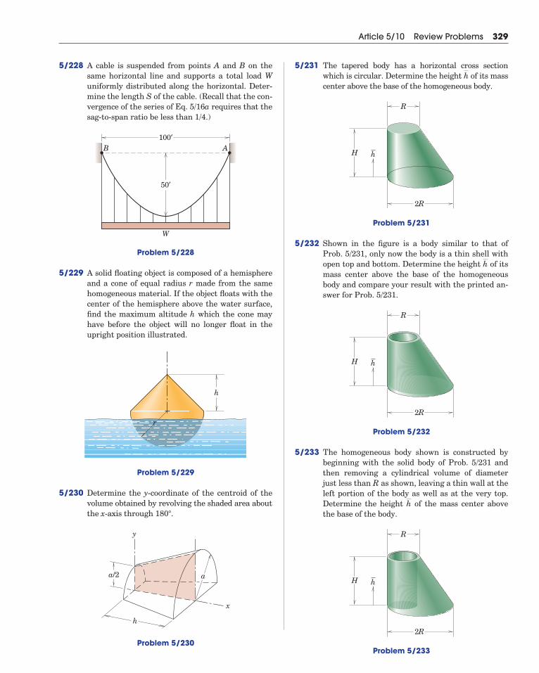
5/228 A cable is suspended from points A and B on thesame horizontal line and supports a total load Wuniformly distributed along the horizontal. Deter-mine the length S of the cable. (Recall that the con-vergence of the series of Eq. 5/16a requires that thesag-to-span ratio be less than 1/4.)
Problem 5/228
5/229 A solid floating object is composed of a hemisphereand a cone of equal radius r made from the samehomogeneous material. If the object floats with thecenter of the hemisphere above the water surface,find the maximum altitude h which the cone mayhave before the object will no longer float in theupright position illustrated.
Problem 5/229
5/230 Determine the y-coordinate of the centroid of thevolume obtained by revolving the shaded area aboutthe x-axis through .
Problem 5/230
y
aa/2
x
h
180�
r
h
B
W
100′
50′
A
Article 5/10 Review Problems 329
5/231 The tapered body has a horizontal cross sectionwhich is circular. Determine the height of its masscenter above the base of the homogeneous body.
Problem 5/231
5/232 Shown in the figure is a body similar to that ofProb. 5/231, only now the body is a thin shell withopen top and bottom. Determine the height of itsmass center above the base of the homogeneousbody and compare your result with the printed an-swer for Prob. 5/231.
Problem 5/232
5/233 The homogeneous body shown is constructed bybeginning with the solid body of Prob. 5/231 andthen removing a cylindrical volume of diameterjust less than R as shown, leaving a thin wall at theleft portion of the body as well as at the very top.Determine the height of the mass center abovethe base of the body.
Problem 5/233
2R
R
H h
h
2R
R
H h
h
2R
R
H h
h
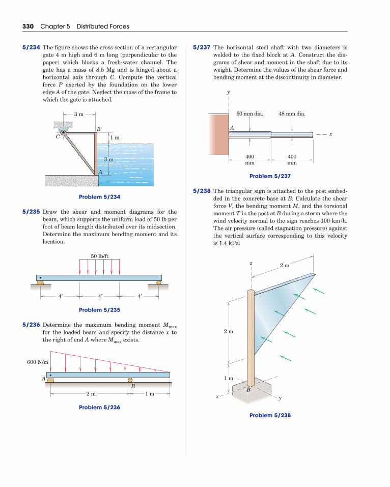
5/237 The horizontal steel shaft with two diameters iswelded to the fixed block at A. Construct the dia-grams of shear and moment in the shaft due to itsweight. Determine the values of the shear force andbending moment at the discontinuity in diameter.
Problem 5/237
5/238 The triangular sign is attached to the post embed-ded in the concrete base at B. Calculate the shearforce V, the bending moment M, and the torsionalmoment T in the post at B during a storm where thewind velocity normal to the sign reaches 100 .The air pressure (called stagnation pressure) againstthe vertical surface corresponding to this velocityis 1.4 kPa.
Problem 5/238
2 m
1 m
2 m
Bx y
z
km /h
400mm
400mm
60 mm dia. 48 mm dia.
y
xA
330 Chapter 5 Distributed Forces
5/234 The figure shows the cross section of a rectangulargate 4 m high and 6 m long (perpendicular to thepaper) which blocks a fresh-water channel. Thegate has a mass of 8.5 Mg and is hinged about ahorizontal axis through C. Compute the verticalforce P exerted by the foundation on the loweredge A of the gate. Neglect the mass of the frame towhich the gate is attached.
Problem 5/234
5/235 Draw the shear and moment diagrams for thebeam, which supports the uniform load of 50 lb perfoot of beam length distributed over its midsection.Determine the maximum bending moment and itslocation.
Problem 5/235
5/236 Determine the maximum bending moment for the loaded beam and specify the distance x tothe right of end A where exists.
Problem 5/236
2 m 1 m
600 N/m
AB
Mmax
Mmax
4′ 4′ 4′
50 lb/ft
3 m
3 m
1 m
B
A
C
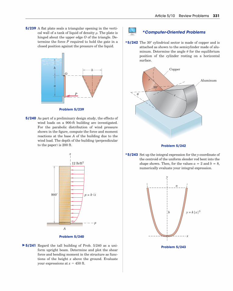
5/239 A flat plate seals a triangular opening in the verti-cal wall of a tank of liquid of density . The plate ishinged about the upper edge O of the triangle. De-termine the force P required to hold the gate in aclosed position against the pressure of the liquid.
Problem 5/239
5/240 As part of a preliminary design study, the effects ofwind loads on a 900-ft building are investigated.For the parabolic distribution of wind pressureshown in the figure, compute the force and momentreactions at the base A of the building due to thewind load. The depth of the building (perpendicularto the paper) is 200 ft.
Problem 5/240
5/241 Regard the tall building of Prob. 5/240 as a uni-form upright beam. Determine and plot the shearforce and bending moment in the structure as func-tions of the height x above the ground. Evaluateyour expressions at .x � 450 ft
900′
x
p
A
12 lb/ft2
p = k x
Ob
h
a
P
�
Article 5/10 Review Problems 331
*Computer-Oriented Problems
5/242 The cylindrical sector is made of copper and isattached as shown to the semicylinder made of alu-minum. Determine the angle for the equilibriumposition of the cylinder resting on a horizontal surface.
Problem 5/242
5/243 Set up the integral expression for the y-coordinate ofthe centroid of the uniform slender rod bent into theshape shown. Then, for the values a = 2 and b = 8,numerically evaluate your integral expression.
Problem 5/243
y
y = k|x|3
x
b
a
θ
r
30°
Copper
r
Aluminum
�
30�
�
*
*
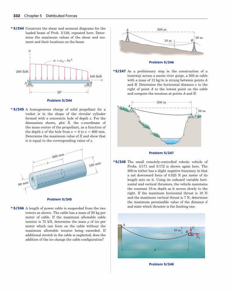
Problem 5/246
5/247 As a preliminary step in the construction of atramway across a scenic river gorge, a 505-m cablewith a mass of is strung between points Aand B. Determine the horizontal distance x to theright of point A to the lowest point on the cableand compute the tensions at points A and B.
Problem 5/247
5/248 The small remotely-controlled robotic vehicle ofProbs. 5/171 and 5/172 is shown again here. The200-m tether has a slight negative buoyancy in thata net downward force of 0.025 N per meter of itslength acts on it. Using its onboard variable hori-zontal and vertical thrusters, the vehicle maintainsthe constant 10-m depth as it moves slowly to theright. If the maximum horizontal thrust is 10 Nand the maximum vertical thrust is 7 N, determinethe maximum permissible value of the distance dand state which thruster is the limiting one.
Problem 5/248
d
10 m
A
BTv
Th
500 m
50 mA
B
12 kg /m
10 m
200 mA
B30 m
332 Chapter 5 Distributed Forces
5/244 Construct the shear and moment diagrams for theloaded beam of Prob. 5/120, repeated here. Deter-mine the maximum values of the shear and mo-ment and their locations on the beam.
Problem 5/244
5/245 A homogeneous charge of solid propellant for arocket is in the shape of the circular cylinderformed with a concentric hole of depth x. For thedimensions shown, plot , the x-coordinate of the mass center of the propellant, as a function ofthe depth x of the hole from x = 0 to x = 600 mm.Determine the maximum value of and show thatit is equal to the corresponding value of x.
Problem 5/245
5/246 A length of power cable is suspended from the twotowers as shown. The cable has a mass of 20 kg permeter of cable. If the maximum allowable cabletension is 75 kN, determine the mass of ice permeter which can form on the cable without themaximum allowable tension being exceeded. If additional stretch in the cable is neglected, does theaddition of the ice change the cable configuration?
�
600 mm
90 mm
180 mmx
X
X
A B
w = w0 – kx3
w
x100 lb/ft
20′
200 lb/ft
*
*
*
*
*

This page intentionally left blank
Large changes in tension can occur when a line is wrapped around a fixed cylinder.
© STOCK4B-RoyaltyFree/Image Source
335
6/1 Introduction
Section A Frictional Phenomena
6/2 Types of Friction
6/3 Dry Friction
Section B Applications of Friction in Machines
6/4 Wedges
6/5 Screws
6/6 Journal Bearings
6/7 Thrust Bearings; Disk Friction
6/8 Flexible Belts
6/9 Rolling Resistance
6/10 Chapter Review
CHAPTER OUTLINE
6Friction
6/1 IntroductionIn the preceding chapters we have usually assumed that the forces
of action and reaction between contacting surfaces act normal to thesurfaces. This assumption characterizes the interaction between smoothsurfaces and was illustrated in Example 2 of Fig. 3/1. Although thisideal assumption often involves only a relatively small error, there aremany problems in which we must consider the ability of contacting sur-faces to support tangential as well as normal forces. Tangential forcesgenerated between contacting surfaces are called friction forces andoccur to some degree in the interaction between all real surfaces. When-ever a tendency exists for one contacting surface to slide along anothersurface, the friction forces developed are always in a direction to opposethis tendency.
In some types of machines and processes we want to minimize theretarding effect of friction forces. Examples are bearings of all types,power screws, gears, the flow of fluids in pipes, and the propulsion ofaircraft and missiles through the atmosphere. In other situations wewish to maximize the effects of friction, as in brakes, clutches, beltdrives, and wedges. Wheeled vehicles depend on friction for both start-ing and stopping, and ordinary walking depends on friction between theshoe and the ground.
Friction forces are present throughout nature and exist in all ma-chines no matter how accurately constructed or carefully lubricated. Amachine or process in which friction is small enough to be neglected issaid to be ideal. When friction must be taken into account, the machineor process is termed real. In all cases where there is sliding motion be-tween parts, the friction forces result in a loss of energy which is dissi-pated in the form of heat. Wear is another effect of friction.
SECTION A FRICTIONAL PHENOMENA
6/2 Types of FrictionIn this article we briefly discuss the types of frictional resistance en-
countered in mechanics. The next article contains a more detailed ac-count of the most common type of friction, dry friction.
(a) Dry Friction. Dry friction occurs when the unlubricated surfacesof two solids are in contact under a condition of sliding or a tendency toslide. A friction force tangent to the surfaces of contact occurs both dur-ing the interval leading up to impending slippage and while slippagetakes place. The direction of this friction force always opposes the mo-tion or impending motion. This type of friction is also called Coulombfriction. The principles of dry or Coulomb friction were developedlargely from the experiments of Coulomb in 1781 and from the work ofMorin from 1831 to 1834. Although we do not yet have a comprehensivetheory of dry friction, in Art. 6/3 we describe an analytical model suffi-cient to handle the vast majority of problems involving dry friction. Thismodel forms the basis for most of this chapter.
(b) Fluid Friction. Fluid friction occurs when adjacent layers in afluid (liquid or gas) are moving at different velocities. This motioncauses frictional forces between fluid elements, and these forces dependon the relative velocity between layers. When there is no relative veloc-ity, there is no fluid friction. Fluid friction depends not only on the ve-locity gradients within the fluid but also on the viscosity of the fluid,which is a measure of its resistance to shearing action between fluid lay-ers. Fluid friction is treated in the study of fluid mechanics and will notbe discussed further in this book.
(c) Internal Friction. Internal friction occurs in all solid materialswhich are subjected to cyclical loading. For highly elastic materials therecovery from deformation occurs with very little loss of energy due tointernal friction. For materials which have low limits of elasticity andwhich undergo appreciable plastic deformation during loading, a consid-erable amount of internal friction may accompany this deformation.The mechanism of internal friction is associated with the action of sheardeformation, which is discussed in references on materials science. Be-cause this book deals primarily with the external effects of forces, wewill not discuss internal friction further.
336 Chapter 6 Friction
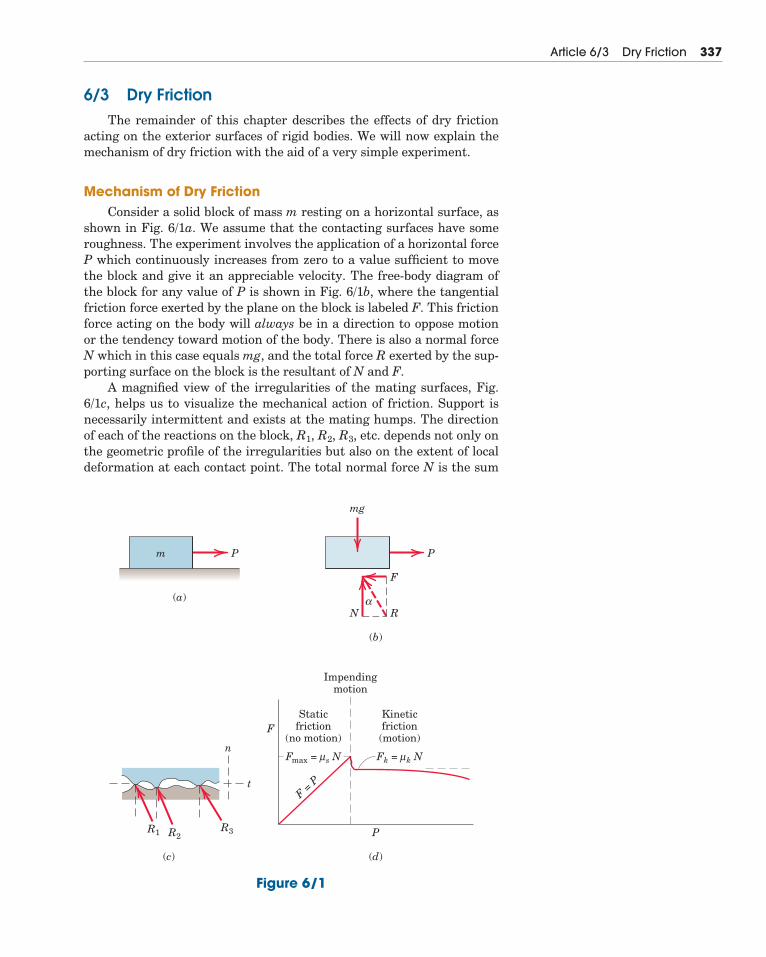
6/3 Dry FrictionThe remainder of this chapter describes the effects of dry friction
acting on the exterior surfaces of rigid bodies. We will now explain themechanism of dry friction with the aid of a very simple experiment.
Mechanism of Dry FrictionConsider a solid block of mass m resting on a horizontal surface, as
shown in Fig. 6/1a. We assume that the contacting surfaces have someroughness. The experiment involves the application of a horizontal forceP which continuously increases from zero to a value sufficient to movethe block and give it an appreciable velocity. The free-body diagram ofthe block for any value of P is shown in Fig. 6/1b, where the tangentialfriction force exerted by the plane on the block is labeled F. This frictionforce acting on the body will always be in a direction to oppose motionor the tendency toward motion of the body. There is also a normal forceN which in this case equals mg, and the total force R exerted by the sup-porting surface on the block is the resultant of N and F.
A magnified view of the irregularities of the mating surfaces, Fig.6/1c, helps us to visualize the mechanical action of friction. Support isnecessarily intermittent and exists at the mating humps. The directionof each of the reactions on the block, R1, R2, R3, etc. depends not only onthe geometric profile of the irregularities but also on the extent of localdeformation at each contact point. The total normal force N is the sum
Article 6/3 Dry Friction 337
Pm P
F
αRN
mg
(a)
(c)
t
n
F
F = P
Fmax = s Nμ Fk = k Nμ
R1 R3R2
(b)
P
Staticfriction
(no motion)
Kineticfriction(motion)
Impendingmotion
(d)
Figure 6/1
of the n-components of the R’s, and the total frictional force F is thesum of the t-components of the R’s. When the surfaces are in relativemotion, the contacts are more nearly along the tops of the humps, andthe t-components of the R’s are smaller than when the surfaces are atrest relative to one another. This observation helps to explain the well-known fact that the force P necessary to maintain motion is generallyless than that required to start the block when the irregularities aremore nearly in mesh.
If we perform the experiment and record the friction force F as afunction of P, we obtain the relation shown in Fig. 6/1d. When P iszero, equilibrium requires that there be no friction force. As P is in-creased, the friction force must be equal and opposite to P as long asthe block does not slip. During this period the block is in equilibrium,and all forces acting on the block must satisfy the equilibrium equa-tions. Finally, we reach a value of P which causes the block to slip andto move in the direction of the applied force. At this same time thefriction force decreases slightly and abruptly. It then remains essen-tially constant for a time but then decreases still more as the velocityincreases.
Static FrictionThe region in Fig. 6/1d up to the point of slippage or impending mo-
tion is called the range of static friction, and in this range the value ofthe friction force is determined by the equations of equilibrium. Thisfriction force may have any value from zero up to and including themaximum value. For a given pair of mating surfaces the experimentshows that this maximum value of static friction Fmax is proportional tothe normal force N. Thus, we may write
(6/1)
where �s is the proportionality constant, called the coefficient of staticfriction.
Be aware that Eq. 6/1 describes only the limiting or maximum valueof the static friction force and not any lesser value. Thus, the equationapplies only to cases where motion is impending with the friction forceat its peak value. For a condition of static equilibrium when motion isnot impending, the static friction force is
Kinetic FrictionAfter slippage occurs, a condition of kinetic friction accompanies the
ensuing motion. Kinetic friction force is usually somewhat less than themaximum static friction force. The kinetic friction force Fk is also pro-portional to the normal force. Thus,
(6/2)Fk � �kN
F � �sN
Fmax � �sN
338 Chapter 6 Friction
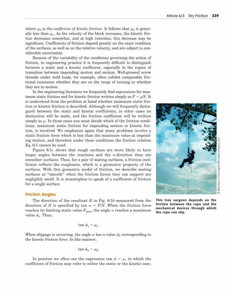
where �k is the coefficient of kinetic friction. It follows that �k is gener-ally less than �s. As the velocity of the block increases, the kinetic fric-tion decreases somewhat, and at high velocities, this decrease may besignificant. Coefficients of friction depend greatly on the exact conditionof the surfaces, as well as on the relative velocity, and are subject to con-siderable uncertainty.
Because of the variability of the conditions governing the action offriction, in engineering practice it is frequently difficult to distinguishbetween a static and a kinetic coefficient, especially in the region oftransition between impending motion and motion. Well-greased screwthreads under mild loads, for example, often exhibit comparable fric-tional resistance whether they are on the verge of turning or whetherthey are in motion.
In the engineering literature we frequently find expressions for max-imum static friction and for kinetic friction written simply as F � �N. Itis understood from the problem at hand whether maximum static fric-tion or kinetic friction is described. Although we will frequently distin-guish between the static and kinetic coefficients, in other cases nodistinction will be made, and the friction coefficient will be writtensimply as �. In those cases you must decide which of the friction condi-tions, maximum static friction for impending motion or kinetic fric-tion, is involved. We emphasize again that many problems involve astatic friction force which is less than the maximum value at impend-ing motion, and therefore under these conditions the friction relationEq. 6/1 cannot be used.
Figure 6/1c shows that rough surfaces are more likely to havelarger angles between the reactions and the n-direction than aresmoother surfaces. Thus, for a pair of mating surfaces, a friction coef-ficient reflects the roughness, which is a geometric property of thesurfaces. With this geometric model of friction, we describe matingsurfaces as “smooth” when the friction forces they can support arenegligibly small. It is meaningless to speak of a coefficient of frictionfor a single surface.
Friction AnglesThe direction of the resultant R in Fig. 6/1b measured from the
direction of N is specified by tan � � F/N. When the friction forcereaches its limiting static value Fmax, the angle � reaches a maximumvalue �s. Thus,
When slippage is occurring, the angle � has a value �k corresponding tothe kinetic friction force. In like manner,
In practice we often see the expression tan � � �, in which thecoefficient of friction may refer to either the static or the kinetic case,
tan �k � �k
tan �s � �s
Article 6/3 Dry Friction 339
This tree surgeon depends on thefriction between the rope and themechanical devices through whichthe rope can slip.
© B
lac
kou
t C
on
ce
pts
/Sto
ckp
ho
top
ro, I
nc
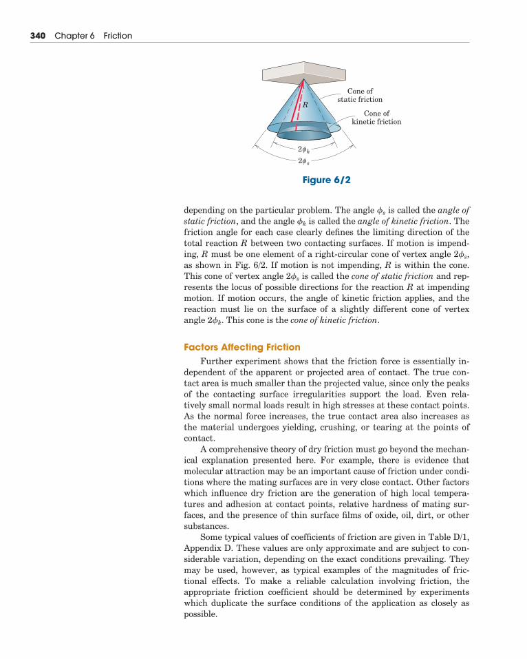
depending on the particular problem. The angle �s is called the angle ofstatic friction, and the angle �k is called the angle of kinetic friction. Thefriction angle for each case clearly defines the limiting direction of thetotal reaction R between two contacting surfaces. If motion is impend-ing, R must be one element of a right-circular cone of vertex angle 2�s,as shown in Fig. 6/2. If motion is not impending, R is within the cone.This cone of vertex angle 2�s is called the cone of static friction and rep-resents the locus of possible directions for the reaction R at impendingmotion. If motion occurs, the angle of kinetic friction applies, and thereaction must lie on the surface of a slightly different cone of vertexangle 2�k. This cone is the cone of kinetic friction.
Factors Affecting FrictionFurther experiment shows that the friction force is essentially in-
dependent of the apparent or projected area of contact. The true con-tact area is much smaller than the projected value, since only the peaksof the contacting surface irregularities support the load. Even rela-tively small normal loads result in high stresses at these contact points.As the normal force increases, the true contact area also increases asthe material undergoes yielding, crushing, or tearing at the points ofcontact.
A comprehensive theory of dry friction must go beyond the mechan-ical explanation presented here. For example, there is evidence thatmolecular attraction may be an important cause of friction under condi-tions where the mating surfaces are in very close contact. Other factorswhich influence dry friction are the generation of high local tempera-tures and adhesion at contact points, relative hardness of mating sur-faces, and the presence of thin surface films of oxide, oil, dirt, or othersubstances.
Some typical values of coefficients of friction are given in Table D/1,Appendix D. These values are only approximate and are subject to con-siderable variation, depending on the exact conditions prevailing. Theymay be used, however, as typical examples of the magnitudes of fric-tional effects. To make a reliable calculation involving friction, theappropriate friction coefficient should be determined by experimentswhich duplicate the surface conditions of the application as closely aspossible.
340 Chapter 6 Friction
Cone ofstatic friction
2 kφ2 sφ
Cone ofkinetic friction
R
Figure 6/2
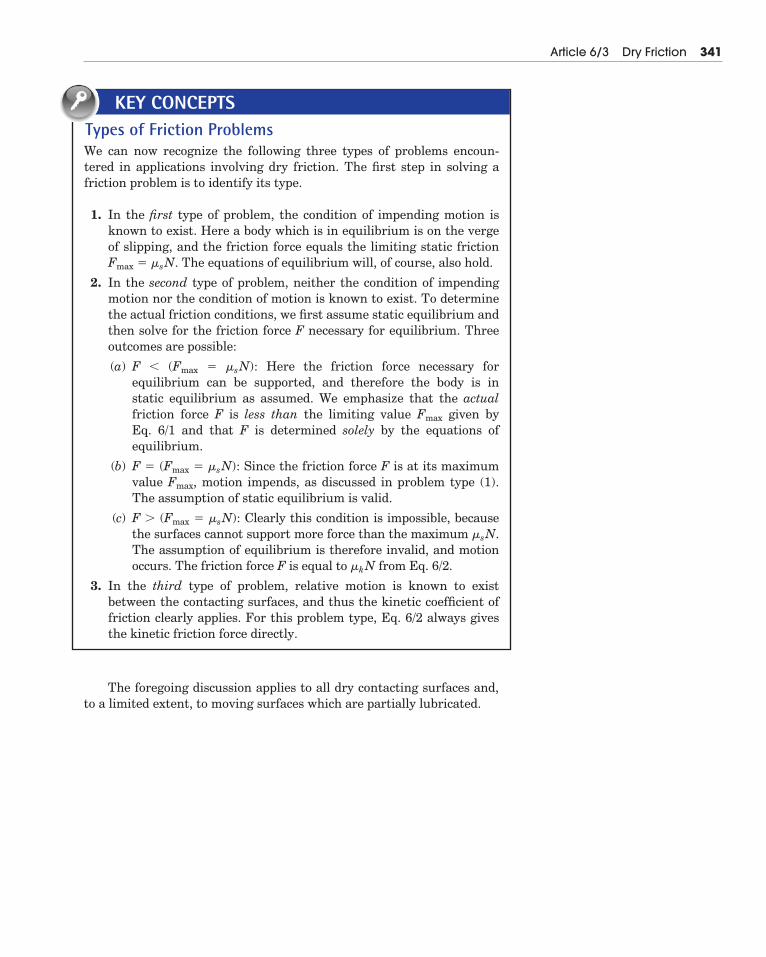
Article 6/3 Dry Friction 341
Types of Friction ProblemsWe can now recognize the following three types of problems encoun-tered in applications involving dry friction. The first step in solving afriction problem is to identify its type.
1. In the first type of problem, the condition of impending motion isknown to exist. Here a body which is in equilibrium is on the vergeof slipping, and the friction force equals the limiting static frictionFmax � �sN. The equations of equilibrium will, of course, also hold.
2. In the second type of problem, neither the condition of impendingmotion nor the condition of motion is known to exist. To determinethe actual friction conditions, we first assume static equilibrium andthen solve for the friction force F necessary for equilibrium. Threeoutcomes are possible:
(a) F � (Fmax � �sN): Here the friction force necessary for equilibrium can be supported, and therefore the body is in static equilibrium as assumed. We emphasize that the actualfriction force F is less than the limiting value Fmax given by Eq. 6/1 and that F is determined solely by the equations of equilibrium.
(b) F � (Fmax � �sN): Since the friction force F is at its maximumvalue Fmax, motion impends, as discussed in problem type (1).The assumption of static equilibrium is valid.
(c) F � (Fmax � �sN): Clearly this condition is impossible, becausethe surfaces cannot support more force than the maximum �sN.The assumption of equilibrium is therefore invalid, and motionoccurs. The friction force F is equal to �kN from Eq. 6/2.
3. In the third type of problem, relative motion is known to exist between the contacting surfaces, and thus the kinetic coefficient offriction clearly applies. For this problem type, Eq. 6/2 always givesthe kinetic friction force directly.
KEY CONCEPTS
The foregoing discussion applies to all dry contacting surfaces and,to a limited extent, to moving surfaces which are partially lubricated.
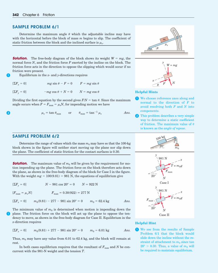
SAMPLE PROBLEM 6/1
Determine the maximum angle � which the adjustable incline may havewith the horizontal before the block of mass m begins to slip. The coefficient ofstatic friction between the block and the inclined surface is �s.
Solution. The free-body diagram of the block shows its weight W � mg, thenormal force N, and the friction force F exerted by the incline on the block. Thefriction force acts in the direction to oppose the slipping which would occur if nofriction were present.
Equilibrium in the x- and y-directions requires
Dividing the first equation by the second gives F/N � tan �. Since the maximumangle occurs when F � Fmax � �sN, for impending motion we have
Ans.
SAMPLE PROBLEM 6/2
Determine the range of values which the mass m0 may have so that the 100-kgblock shown in the figure will neither start moving up the plane nor slip downthe plane. The coefficient of static friction for the contact surfaces is 0.30.
Solution. The maximum value of m0 will be given by the requirement for mo-tion impending up the plane. The friction force on the block therefore acts downthe plane, as shown in the free-body diagram of the block for Case I in the figure.With the weight mg � 100(9.81) � 981 N, the equations of equilibrium give
Ans.
The minimum value of m0 is determined when motion is impending down theplane. The friction force on the block will act up the plane to oppose the ten-dency to move, as shown in the free-body diagram for Case II. Equilibrium in thex-direction requires
Ans.
Thus, m0 may have any value from 6.01 to 62.4 kg, and the block will remain atrest.
In both cases equilibrium requires that the resultant of Fmax and N be con-current with the 981-N weight and the tension T.
m0(9.81) � 277 � 981 sin 20� � 0 m0 � 6.01 kg[ΣFx � 0]
m0(9.81) � 277 � 981 sin 20� � 0 m0 � 62.4 kg[ΣFx � 0]
Fmax � 0.30(922) � 277 N[Fmax � �sN]
N � 981 cos 20� � 0 N � 922 N[ΣFy � 0]
�s � tan �max or �max � tan�1 �s
�mg cos � � N � 0 N � mg cos �[ΣFy � 0]
mg sin � � F � 0 F � mg sin �[ΣFx � 0]
342 Chapter 6 Friction
m
θsμ
x
y
F N
W = mg
θ
20° m0
100 kg
20°
981 N
N
Case I
x
y
Fmax
Fmax
T = m0g
20°
981 N
N
Case II
x
y
T = m0g
�
�
�
Helpful Hints
� We choose reference axes along andnormal to the direction of F toavoid resolving both F and N intocomponents.
� This problem describes a very simpleway to determine a static coefficientof friction. The maximum value of �is known as the angle of repose.
Helpful Hint
� We see from the results of SampleProblem 6/1 that the block wouldslide down the incline without the re-straint of attachment to m0 since tan20� � 0.30. Thus, a value of m0 willbe required to maintain equilibrium.
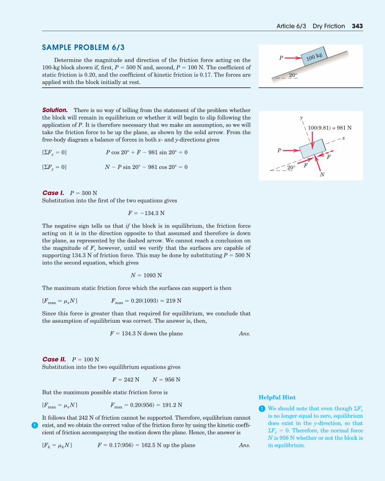
SAMPLE PROBLEM 6/3
Determine the magnitude and direction of the friction force acting on the100-kg block shown if, first, P � 500 N and, second, P � 100 N. The coefficient ofstatic friction is 0.20, and the coefficient of kinetic friction is 0.17. The forces areapplied with the block initially at rest.
Solution. There is no way of telling from the statement of the problem whetherthe block will remain in equilibrium or whether it will begin to slip following theapplication of P. It is therefore necessary that we make an assumption, so we willtake the friction force to be up the plane, as shown by the solid arrow. From thefree-body diagram a balance of forces in both x- and y-directions gives
Case I. P � 500 NSubstitution into the first of the two equations gives
The negative sign tells us that if the block is in equilibrium, the friction forceacting on it is in the direction opposite to that assumed and therefore is downthe plane, as represented by the dashed arrow. We cannot reach a conclusion onthe magnitude of F, however, until we verify that the surfaces are capable ofsupporting 134.3 N of friction force. This may be done by substituting P � 500 Ninto the second equation, which gives
The maximum static friction force which the surfaces can support is then
Since this force is greater than that required for equilibrium, we conclude thatthe assumption of equilibrium was correct. The answer is, then,
Ans.
Case II. P � 100 NSubstitution into the two equilibrium equations gives
But the maximum possible static friction force is
It follows that 242 N of friction cannot be supported. Therefore, equilibrium cannotexist, and we obtain the correct value of the friction force by using the kinetic coeffi-cient of friction accompanying the motion down the plane. Hence, the answer is
Ans.F � 0.17(956) � 162.5 N up the plane[Fk � �kN ]
Fmax � 0.20(956) � 191.2 N[Fmax � �sN ]
F � 242 N N � 956 N
F � 134.3 N down the plane
Fmax � 0.20(1093) � 219 N[Fmax � �sN ]
N � 1093 N
F � �134.3 N
N � P sin 20� � 981 cos 20� � 0[ΣFy � 0]
P cos 20� � F � 981 sin 20� � 0[ΣFx � 0]
Article 6/3 Dry Friction 343
20°
P 100 kg
20°
100(9.81) = 981 N
P
N
F
x
y
F
�
Helpful Hint
� We should note that even though ΣFx
is no longer equal to zero, equilibriumdoes exist in the y-direction, so thatΣFy � 0. Therefore, the normal forceN is 956 N whether or not the block isin equilibrium.
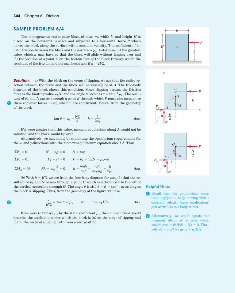
SAMPLE PROBLEM 6/4
The homogeneous rectangular block of mass m, width b, and height H isplaced on the horizontal surface and subjected to a horizontal force P whichmoves the block along the surface with a constant velocity. The coefficient of ki-netic friction between the block and the surface is �k. Determine (a) the greatestvalue which h may have so that the block will slide without tipping over and (b) the location of a point C on the bottom face of the block through which theresultant of the friction and normal forces acts if h � H/2.
Solution. (a) With the block on the verge of tipping, we see that the entire re-action between the plane and the block will necessarily be at A. The free-bodydiagram of the block shows this condition. Since slipping occurs, the frictionforce is the limiting value �kN, and the angle � becomes � � tan�1 �k. The resul-tant of Fk and N passes through a point B through which P must also pass, sincethree coplanar forces in equilibrium are concurrent. Hence, from the geometryof the block
Ans.
If h were greater than this value, moment equilibrium about A would not besatisfied, and the block would tip over.
Alternatively, we may find h by combining the equilibrium requirements forthe x- and y-directions with the moment-equilibrium equation about A. Thus,
Ans.
(b) With h � H/2 we see from the free-body diagram for case (b) that the re-sultant of Fk and N passes through a point C which is a distance x to the left ofthe vertical centerline through G. The angle � is still � � � � tan�1 �k as long asthe block is slipping. Thus, from the geometry of the figure we have
Ans.
If we were to replace �k by the static coefficient �s, then our solutions woulddescribe the conditions under which the block is (a) on the verge of tipping and(b) on the verge of slipping, both from a rest position.
xH/2
� tan � � �k so x � �kH/2
Ph � mg b2
� 0 h �mgb2P
�mgb
2�kmg�
b2�k
[ΣMA � 0]
Fk � P � 0 P � Fk � �kN � �kmg[ΣFx � 0]
N � mg � 0 N � mg[ΣFy � 0]
tan � � �k �b/2h
h �b
2�k
344 Chapter 6 Friction
Pm
b
Hh
PG
mg
θ
θ
x
y
B
A
N
Fk
h
b—2
PG
mgθ
θ
C
N
xFk
H—2
�
�
Helpful Hints
� Recall that the equilibrium equa-tions apply to a body moving with aconstant velocity (zero acceleration)just as well as to a body at rest.
� Alternatively, we could equate themoments about G to zero, whichwould give us F(H/2) � Nx � 0. Thus,with Fk � �kN we get x � �xH/2.
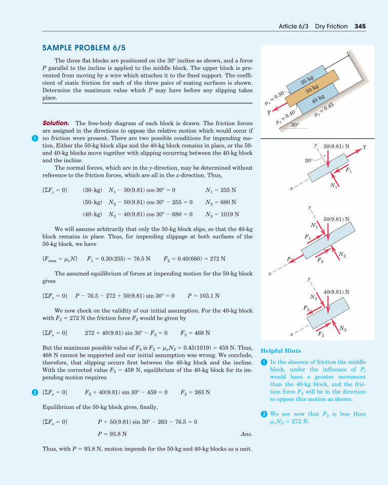
SAMPLE PROBLEM 6/5
The three flat blocks are positioned on the 30� incline as shown, and a forceP parallel to the incline is applied to the middle block. The upper block is pre-vented from moving by a wire which attaches it to the fixed support. The coeffi-cient of static friction for each of the three pairs of mating surfaces is shown.Determine the maximum value which P may have before any slipping takesplace.
Solution. The free-body diagram of each block is drawn. The friction forcesare assigned in the directions to oppose the relative motion which would occur if no friction were present. There are two possible conditions for impending mo-tion. Either the 50-kg block slips and the 40-kg block remains in place, or the 50-and 40-kg blocks move together with slipping occurring between the 40-kg blockand the incline.
The normal forces, which are in the y-direction, may be determined withoutreference to the friction forces, which are all in the x-direction. Thus,
We will assume arbitrarily that only the 50-kg block slips, so that the 40-kgblock remains in place. Thus, for impending slippage at both surfaces of the 50-kg block, we have
The assumed equilibrium of forces at impending motion for the 50-kg blockgives
We now check on the validity of our initial assumption. For the 40-kg blockwith F2 � 272 N the friction force F3 would be given by
But the maximum possible value of F3 is F3 � �sN3 � 0.45(1019) � 459 N. Thus,468 N cannot be supported and our initial assumption was wrong. We conclude,therefore, that slipping occurs first between the 40-kg block and the incline.With the corrected value F3 � 459 N, equilibrium of the 40-kg block for its im-pending motion requires
Equilibrium of the 50-kg block gives, finally,
Ans.
Thus, with P � 93.8 N, motion impends for the 50-kg and 40-kg blocks as a unit.
P � 93.8 N
P � 50(9.81) sin 30� � 263 � 76.5 � 0[ΣFx � 0]
F2 � 40(9.81) sin 30� � 459 � 0 F2 � 263 N[ΣFx � 0]
272 � 40(9.81) sin 30� � F3 � 0 F3 � 468 N[ΣFx � 0]
P � 76.5 � 272 � 50(9.81) sin 30� � 0 P � 103.1 N[ΣFx � 0]
F1 � 0.30(255) � 76.5 N F2 � 0.40(680) � 272 N[Fmax � �sN]
(40-kg) N3 � 40(9.81) cos 30� � 680 � 0 N3 � 1019 N
(50-kg) N2 � 50(9.81) cos 30� � 255 � 0 N2 � 680 N
(30-kg) N1 � 30(9.81) cos 30� � 0 N1 � 255 N[ΣFy � 0]
Article 6/3 Dry Friction 345
P
30 kg
s = 0.30
μ
s = 0.40
μ
50 kg
40 kg
30°
s = 0.45
μ
30°
y
P
F1
F2
N2
N1
50(9.81) N
x
y
F1
T
N1
30(9.81) N
x
xy
F2
F3
N3
N2
40(9.81) N
Helpful Hints
� In the absence of friction the middleblock, under the influence of P,would have a greater movementthan the 40-kg block, and the fric-tion force F2 will be in the directionto oppose this motion as shown.
� We see now that F2 is less than�sN2 � 272 N.
�
�
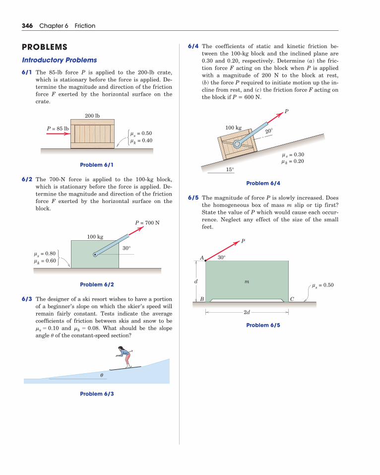
6/4 The coefficients of static and kinetic friction be-tween the 100-kg block and the inclined plane are0.30 and 0.20, respectively. Determine (a) the fric-tion force F acting on the block when P is appliedwith a magnitude of 200 N to the block at rest, (b) the force P required to initiate motion up the in-cline from rest, and (c) the friction force F acting onthe block if P = 600 N.
Problem 6/4
6/5 The magnitude of force P is slowly increased. Doesthe homogeneous box of mass m slip or tip first?State the value of P which would cause each occur-rence. Neglect any effect of the size of the smallfeet.
Problem 6/5
P
d
A
B C
2d
30°
s = 0.50μm
20°
15°
100 kg
P
s = 0.30μk = 0.20μ
346 Chapter 6 Friction
PROBLEMSIntroductory Problems
6/1 The 85-lb force P is applied to the 200-lb crate,which is stationary before the force is applied. De-termine the magnitude and direction of the frictionforce F exerted by the horizontal surface on thecrate.
Problem 6/1
6/2 The 700-N force is applied to the 100-kg block,which is stationary before the force is applied. De-termine the magnitude and direction of the frictionforce F exerted by the horizontal surface on theblock.
Problem 6/2
6/3 The designer of a ski resort wishes to have a portionof a beginner’s slope on which the skier’s speed willremain fairly constant. Tests indicate the average coefficients of friction between skis and snow to be
and . What should be the slopeangle of the constant-speed section?
Problem 6/3
θ
�
�k � 0.08�s � 0.10
100 kg
30°
P = 700 N
s = 0.80μ
k = 0.60μ
P = 85 lb
200 lb
s = 0.50μ
k = 0.40μ
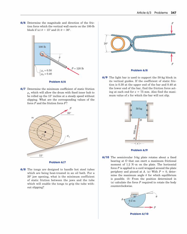
6/6 Determine the magnitude and direction of the fric-tion force which the vertical wall exerts on the 100-lbblock if (a) and (b) .
Problem 6/6
6/7 Determine the minimum coefficient of static frictionwhich will allow the drum with fixed inner hub to
be rolled up the incline at a steady speed withoutslipping. What are the corresponding values of theforce P and the friction force F?
Problem 6/7
6/8 The tongs are designed to handle hot steel tubeswhich are being heat-treated in an oil bath. For a
jaw opening, what is the minimum coefficientof static friction between the jaws and the tubewhich will enable the tongs to grip the tube with-out slipping?
20�
30°
P
15°
m
rr/2 sμ
15�
�s
100 lb
P = 120 lbs = 0.50
θ
μk = 0.40μ
� � 30�� � 15�
Article 6/3 Problems 347
Problem 6/8
6/9 The light bar is used to support the 50-kg block inits vertical guides. If the coefficient of static fric-tion is 0.30 at the upper end of the bar and 0.40 atthe lower end of the bar, find the friction force act-ing at each end for x = 75 mm. Also find the maxi-mum value of x for which the bar will not slip.
Problem 6/9
6/10 The semicircular 5-kg plate rotates about a fixedbearing at O that can exert a maximum frictionalmoment of 1.2 N m on the plate. The horizontalforce P is applied to a cord wrapped around the plateperiphery and pinned at A. (a) With P = 0, deter-mine the maximum angle for which equilibrium is possible. (b) From the position determined in (a) calculate the force P required to rotate the bodycounterclockwise.
Problem 6/10
P
θOA 0.2 m
�
�
50 kg
x
300
mm
A
B
F
F
20°
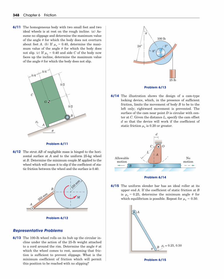
Problem 6/13
6/14 The illustration shows the design of a cam-typelocking device, which, in the presence of sufficientfriction, limits the movement of body B to be to theleft only; rightward movement is prevented. Thesurface of the cam near point D is circular with cen-ter at C. Given the distance L, specify the cam offsetd so that the device will work if the coefficient ofstatic friction is 0.20 or greater.
Problem 6/14
6/15 The uniform slender bar has an ideal roller at itsupper end A. If the coefficient of static friction at Bis , determine the minimum angle forwhich equilibrium is possible. Repeat for .
Problem 6/15
B
A
θms = 0.25, 0.50
�s � 0.50��s � 0.25
OC
d
AL
Allowablemotion
Nomotion
DB
�s
25 lb
24′′
100 lb
3′′
8′′
θ
348 Chapter 6 Friction
6/11 The homogeneous body with two small feet and twoideal wheels is at rest on the rough incline. (a) As-sume no slippage and determine the maximum valueof the angle for which the body does not overturnabout feet A. (b) If , determine the maxi-mum value of the angle for which the body doesnot slip. (c) If and side C of the body nowfaces up the incline, determine the maximum valueof the angle for which the body does not slip.
Problem 6/11
6/12 The strut AB of negligible mass is hinged to the hori-zontal surface at A and to the uniform 25-kg wheel at B. Determine the minimum couple M applied to thewheel which will cause it to slip if the coefficient of sta-tic friction between the wheel and the surface is 0.40.
Problem 6/12
Representative Problems
6/13 The 100-lb wheel rolls on its hub up the circular in-cline under the action of the 25-lb weight attachedto a cord around the rim. Determine the angle atwhich the wheel comes to rest, assuming that fric-tion is sufficient to prevent slippage. What is theminimum coefficient of friction which will permitthis position to be reached with no slipping?
�
A
B 150 m
m
250 mm
M
h/4
h/2
h/4
h/2
C
G
A
B
q
ms
�
�s � 0.40�
�s � 0.40�
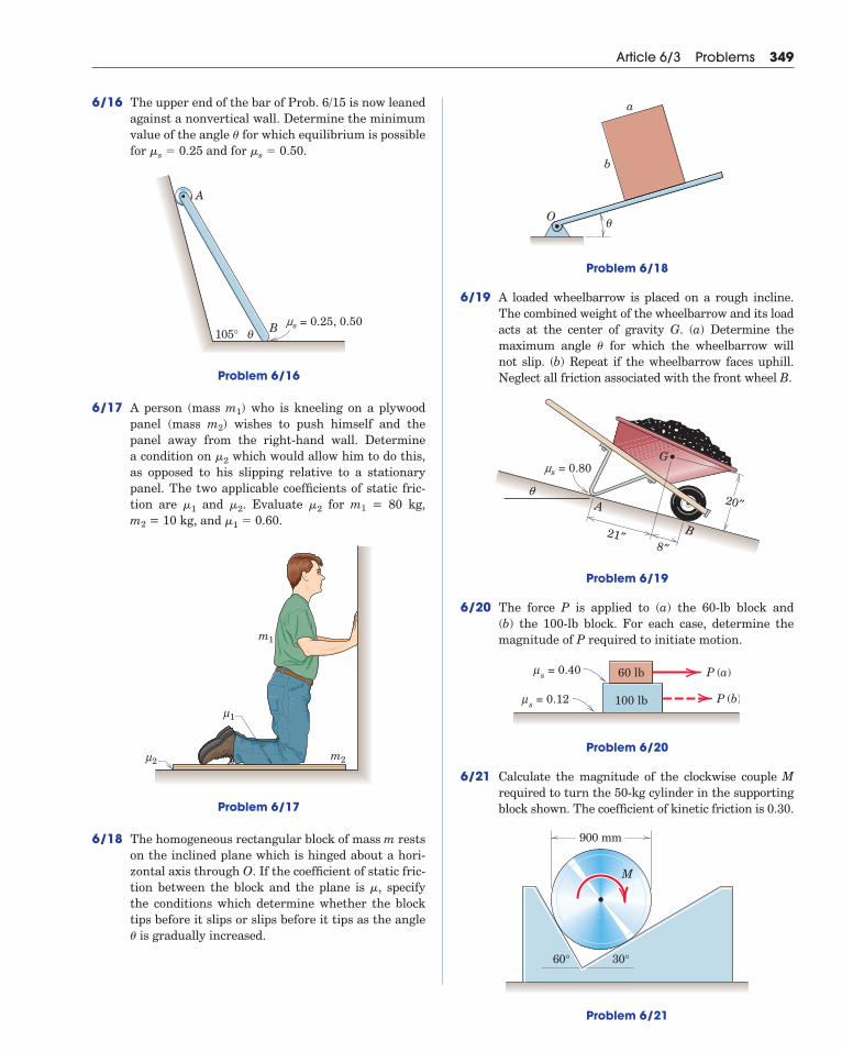
6/16 The upper end of the bar of Prob. 6/15 is now leanedagainst a nonvertical wall. Determine the minimumvalue of the angle for which equilibrium is possiblefor and for .
Problem 6/16
6/17 A person (mass m1) who is kneeling on a plywoodpanel (mass m2) wishes to push himself and thepanel away from the right-hand wall. Determine a condition on which would allow him to do this,as opposed to his slipping relative to a stationarypanel. The two applicable coefficients of static fric-tion are and . Evaluate for m1 = 80 kg, m2 = 10 kg, and .
Problem 6/17
6/18 The homogeneous rectangular block of mass m restson the inclined plane which is hinged about a hori-zontal axis through O. If the coefficient of static fric-tion between the block and the plane is , specifythe conditions which determine whether the blocktips before it slips or slips before it tips as the angle
is gradually increased.�
�
m1
m22μ
1μ
�1 � 0.60�2�2�1
�2
B105° θms = 0.25, 0.50
A
�s � 0.50�s � 0.25�
Article 6/3 Problems 349
Problem 6/18
6/19 A loaded wheelbarrow is placed on a rough incline.The combined weight of the wheelbarrow and its loadacts at the center of gravity G. (a) Determine themaximum angle for which the wheelbarrow will not slip. (b) Repeat if the wheelbarrow faces uphill.Neglect all friction associated with the front wheel B.
Problem 6/19
6/20 The force P is applied to (a) the 60-lb block and (b) the 100-lb block. For each case, determine themagnitude of P required to initiate motion.
Problem 6/20
6/21 Calculate the magnitude of the clockwise couple Mrequired to turn the 50-kg cylinder in the supportingblock shown. The coefficient of kinetic friction is 0.30.
Problem 6/21
900 mm
30°
M
60°
60 lb
100 lb
P (a)
P (b)
s = 0.40μ
s = 0.12μ
B
A
G
21″8″
20″
ms = 0.80
q
�
a
O
b
θ
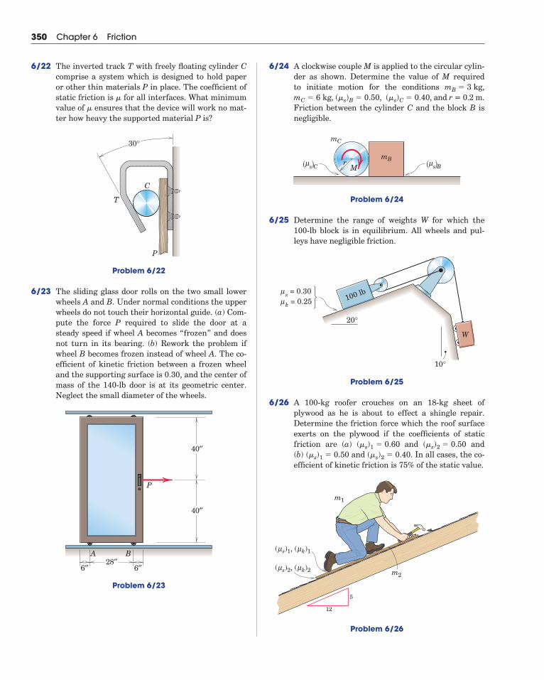
6/24 A clockwise couple M is applied to the circular cylin-der as shown. Determine the value of M requiredto initiate motion for the conditions ,
, , , and r = 0.2 m.Friction between the cylinder C and the block B isnegligible.
Problem 6/24
6/25 Determine the range of weights W for which the100-lb block is in equilibrium. All wheels and pul-leys have negligible friction.
Problem 6/25
6/26 A 100-kg roofer crouches on an 18-kg sheet ofplywood as he is about to effect a shingle repair.Determine the friction force which the roof surfaceexerts on the plywood if the coefficients of staticfriction are (a) and and (b) and . In all cases, the co-efficient of kinetic friction is 75% of the static value.
Problem 6/26
12
5
( s)2, ( k)2μ μ
( s)1, ( k)1μ μ
m2
m1
(�s)2 � 0.40(�s)1 � 0.50(�s)2 � 0.50(�s)1 � 0.60
s = 0.30μ
k = 0.25μ 100 lb
W
20°
10°
mB
mC
s Cμ( ) s Bμ( )rM
(�s)C � 0.40(�s)B � 0.50mC � 6 kgmB � 3 kg
350 Chapter 6 Friction
6/22 The inverted track T with freely floating cylinder Ccomprise a system which is designed to hold paperor other thin materials P in place. The coefficient ofstatic friction is for all interfaces. What minimumvalue of ensures that the device will work no mat-ter how heavy the supported material P is?
Problem 6/22
6/23 The sliding glass door rolls on the two small lowerwheels A and B. Under normal conditions the upperwheels do not touch their horizontal guide. (a) Com-pute the force P required to slide the door at asteady speed if wheel A becomes “frozen” and doesnot turn in its bearing. (b) Rework the problem ifwheel B becomes frozen instead of wheel A. The co-efficient of kinetic friction between a frozen wheeland the supporting surface is 0.30, and the center ofmass of the 140-lb door is at its geometric center.Neglect the small diameter of the wheels.
Problem 6/23
40′′
28′′6′′ 6′′
40′′
P
BA
T
P
C
30°
�
�
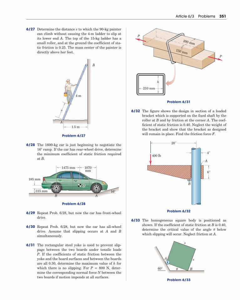
6/27 Determine the distance s to which the 90-kg paintercan climb without causing the 4-m ladder to slip atits lower end A. The top of the 15-kg ladder has asmall roller, and at the ground the coefficient of sta-tic friction is 0.25. The mass center of the painter isdirectly above her feet.
Problem 6/27
6/28 The 1600-kg car is just beginning to negotiate theramp. If the car has rear-wheel drive, determine
the minimum coefficient of static friction requiredat B.
Problem 6/28
6/29 Repeat Prob. 6/28, but now the car has front-wheeldrive.
6/30 Repeat Prob. 6/28, but now the car has all-wheeldrive. Assume that slipping occurs at A and Bsimultaneously.
6/31 The rectangular steel yoke is used to prevent slip-page between the two boards under tensile loadsP. If the coefficients of static friction between theyoke and the board surfaces and between the boardsare all 0.30, determine the maximum value of h forwhich there is no slipping. For P = 800 N, deter-mine the corresponding normal force N between thetwo boards if motion impends at all surfaces.
B A
1070mm
16°
1475 mm
G
315 mm
185 mm
16�
1.5 m
s
4 m
B
A
Article 6/3 Problems 351
Problem 6/31
6/32 The figure shows the design in section of a loadedbracket which is supported on the fixed shaft by theroller at B and by friction at the corner A. The coef-ficient of static friction is 0.40. Neglect the weight ofthe bracket and show that the bracket as designedwill remain in place. Find the friction force F.
Problem 6/32
6/33 The homogeneous square body is positioned asshown. If the coefficient of static friction at B is 0.40,determine the critical value of the angle belowwhich slipping will occur. Neglect friction at A.
Problem 6/33
B
s
s
A
60° θ
�
20"
4"
B
A
6"
400 lb
h
P
P
210 mm
150 mm
200 mm
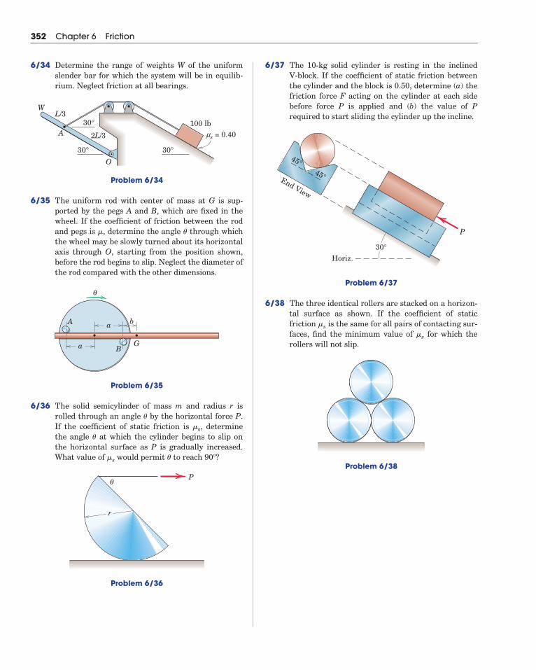
6/37 The 10-kg solid cylinder is resting in the inclinedV-block. If the coefficient of static friction betweenthe cylinder and the block is 0.50, determine (a) thefriction force F acting on the cylinder at each sidebefore force P is applied and (b) the value of Prequired to start sliding the cylinder up the incline.
Problem 6/37
6/38 The three identical rollers are stacked on a horizon-tal surface as shown. If the coefficient of staticfriction is the same for all pairs of contacting sur-faces, find the minimum value of for which therollers will not slip.
Problem 6/38
�s
�s
45°
45°
End View
30°Horiz.
P
352 Chapter 6 Friction
6/34 Determine the range of weights W of the uniformslender bar for which the system will be in equilib-rium. Neglect friction at all bearings.
Problem 6/34
6/35 The uniform rod with center of mass at G is sup-ported by the pegs A and B, which are fixed in thewheel. If the coefficient of friction between the rodand pegs is , determine the angle through whichthe wheel may be slowly turned about its horizontalaxis through O, starting from the position shown,before the rod begins to slip. Neglect the diameter ofthe rod compared with the other dimensions.
Problem 6/35
6/36 The solid semicylinder of mass m and radius r isrolled through an angle by the horizontal force P.If the coefficient of static friction is , determinethe angle at which the cylinder begins to slip onthe horizontal surface as P is gradually increased.What value of would permit to reach ?
Problem 6/36
Pθ
r
90���s
�
�s
�
BG
A
a
a b
θ
��
30°
30°
ms = 0.40100 lb
2L/3
L/3W
A
O
30°
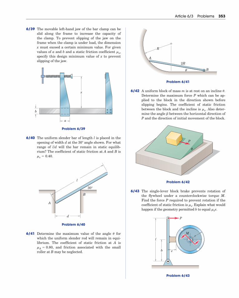
6/39 The movable left-hand jaw of the bar clamp can beslid along the frame to increase the capacity ofthe clamp. To prevent slipping of the jaw on theframe when the clamp is under load, the dimensionx must exceed a certain minimum value. For givenvalues of a and b and a static friction coefficient ,specify this design minimum value of x to preventslipping of the jaw.
Problem 6/39
6/40 The uniform slender bar of length l is placed in theopening of width d at the angle shown. For whatrange of l/d will the bar remain in static equilib-rium? The coefficient of static friction at A and B is
.
Problem 6/40
6/41 Determine the maximum value of the angle forwhich the uniform slender rod will remain in equi-librium. The coefficient of static friction at A is
, and friction associated with the smallroller at B may be neglected.�A � 0.80
�
l
B
A
d
30°
�s � 0.40
30�
x
b
a
�s
Article 6/3 Problems 353
Problem 6/41
6/42 A uniform block of mass m is at rest on an incline .Determine the maximum force P which can be ap-plied to the block in the direction shown before slipping begins. The coefficient of static friction between the block and the incline is . Also deter-mine the angle between the horizontal direction ofP and the direction of initial movement of the block.
Problem 6/42
6/43 The single-lever block brake prevents rotation ofthe flywheel under a counterclockwise torque M.Find the force P required to prevent rotation if thecoefficient of static friction is . Explain what wouldhappen if the geometry permitted b to equal .
Problem 6/43
l
b e
rM
P
�se�s
θ
P
�
�s
�
A
R
B
2R
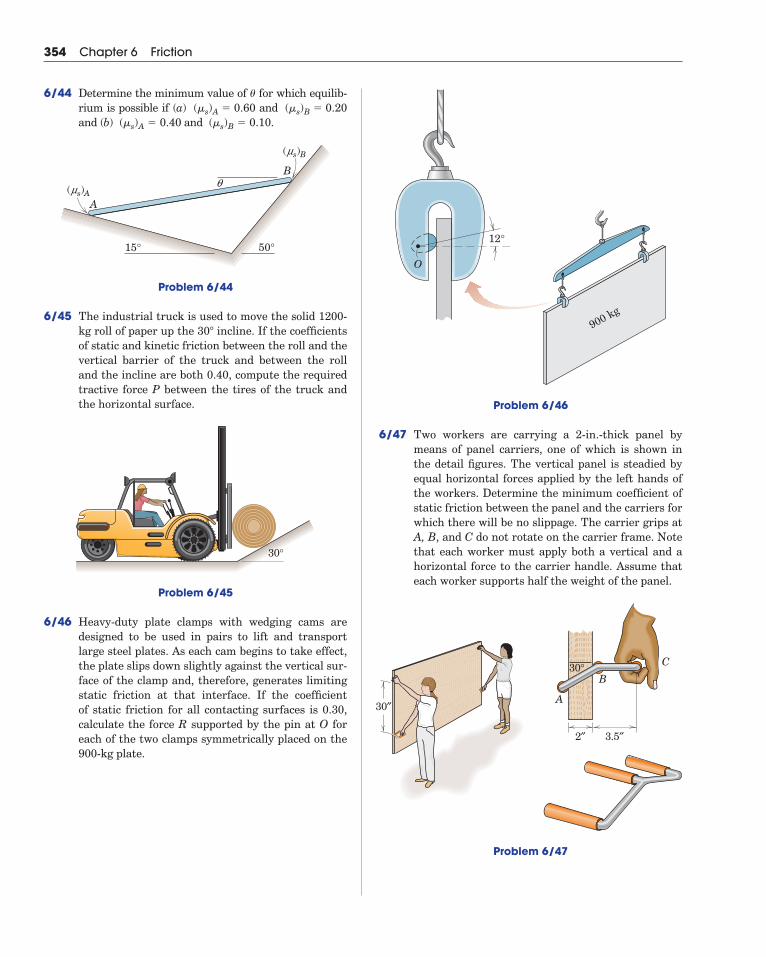
Problem 6/46
6/47 Two workers are carrying a 2-in.-thick panel bymeans of panel carriers, one of which is shown inthe detail figures. The vertical panel is steadied byequal horizontal forces applied by the left hands ofthe workers. Determine the minimum coefficient ofstatic friction between the panel and the carriers forwhich there will be no slippage. The carrier grips atA, B, and C do not rotate on the carrier frame. Notethat each worker must apply both a vertical and ahorizontal force to the carrier handle. Assume thateach worker supports half the weight of the panel.
12°
900 kg
O
354 Chapter 6 Friction
6/44 Determine the minimum value of for which equilib-rium is possible if (a) and and (b) and .
Problem 6/44
6/45 The industrial truck is used to move the solid 1200-kg roll of paper up the incline. If the coefficientsof static and kinetic friction between the roll and thevertical barrier of the truck and between the rolland the incline are both 0.40, compute the requiredtractive force P between the tires of the truck andthe horizontal surface.
Problem 6/45
6/46 Heavy-duty plate clamps with wedging cams aredesigned to be used in pairs to lift and transportlarge steel plates. As each cam begins to take effect,the plate slips down slightly against the vertical sur-face of the clamp and, therefore, generates limitingstatic friction at that interface. If the coefficient of static friction for all contacting surfaces is 0.30,calculate the force R supported by the pin at O foreach of the two clamps symmetrically placed on the900-kg plate.
30°
30�
A
qB
15° 50°
(ms)B
(ms)A
(�s)B � 0.10 (�s)A � 0.40 (�s)B � 0.20 (�s)A � 0.60
�
2″
30″A
B
C
3.5″
30°
Problem 6/47
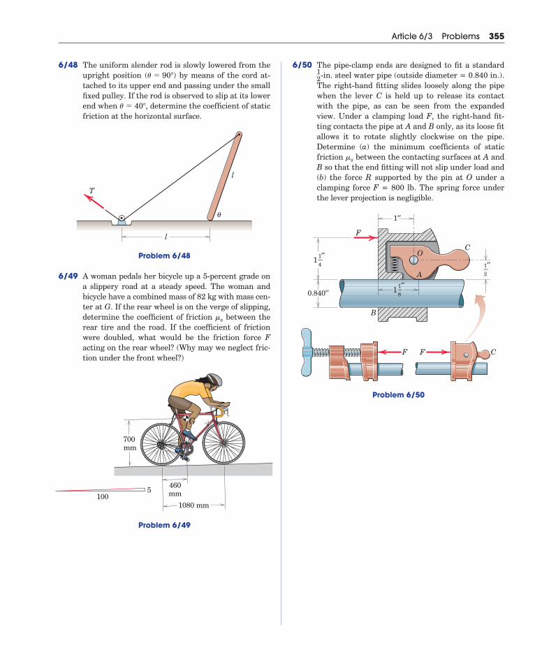
6/48 The uniform slender rod is slowly lowered from theupright position by means of the cord at-tached to its upper end and passing under the smallfixed pulley. If the rod is observed to slip at its lowerend when , determine the coefficient of staticfriction at the horizontal surface.
Problem 6/48
6/49 A woman pedals her bicycle up a 5-percent grade ona slippery road at a steady speed. The woman and bicycle have a combined mass of 82 kg with mass cen-ter at G. If the rear wheel is on the verge of slipping,determine the coefficient of friction between therear tire and the road. If the coefficient of frictionwere doubled, what would be the friction force Facting on the rear wheel? (Why may we neglect fric-tion under the front wheel?)
�s
θ
T
l
l
� � 40�
(� � 90�)
Article 6/3 Problems 355
6/50 The pipe-clamp ends are designed to fit a standard -in. steel water pipe (outside diameter = 0.840 in.).
The right-hand fitting slides loosely along the pipewhen the lever C is held up to release its contactwith the pipe, as can be seen from the expandedview. Under a clamping load F, the right-hand fit-ting contacts the pipe at A and B only, as its loose fitallows it to rotate slightly clockwise on the pipe. Determine (a) the minimum coefficients of staticfriction between the contacting surfaces at A andB so that the end fitting will not slip under load and(b) the force R supported by the pin at O under aclamping force F = 800 lb. The spring force underthe lever projection is negligible.
Problem 6/50
0.840′′
1′′
F F C
C
F
A
B
O1′′–4
11′′–2
1′′–8
1
�s
12
700 mm
460mm
G
1080 mm100
5
Problem 6/49
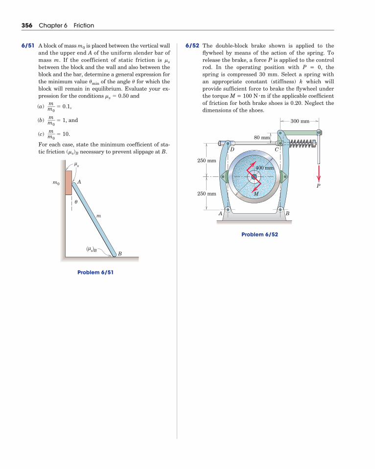
356 Chapter 6 Friction
6/51 A block of mass is placed between the vertical walland the upper end A of the uniform slender bar ofmass m. If the coefficient of static friction is between the block and the wall and also between theblock and the bar, determine a general expression forthe minimum value of the angle for which theblock will remain in equilibrium. Evaluate your ex-pression for the conditions and
(a) � 0.1,
(b) � 1, and
(c) � 10.
For each case, state the minimum coefficient of sta-tic friction (�s)B necessary to prevent slippage at B.
Problem 6/51
s Bμ( )
sμ
θ
m
m0
B
A
mm0
mm0
mm0
�s � 0.50
��min
�s
m0 6/52 The double-block brake shown is applied to the flywheel by means of the action of the spring. Torelease the brake, a force P is applied to the controlrod. In the operating position with P = 0, thespring is compressed 30 mm. Select a spring withan appropriate constant (stiffness) k which will provide sufficient force to brake the flywheel underthe torque M = 100 N m if the applicable coefficientof friction for both brake shoes is 0.20. Neglect thedimensions of the shoes.
Problem 6/52
CD
A B
P
300 mm
80 mm
250 mm
250 mm
400 mm
M
�
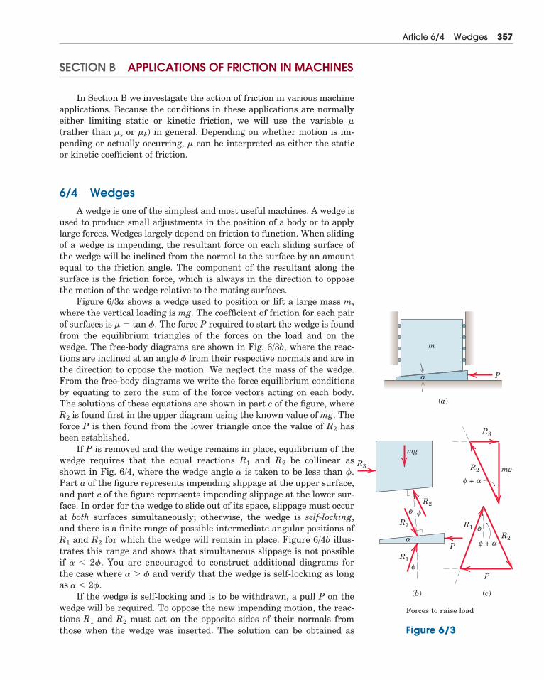
SECTION B APPLICATIONS OF FRICTION IN MACHINES
In Section B we investigate the action of friction in various machineapplications. Because the conditions in these applications are normallyeither limiting static or kinetic friction, we will use the variable �
(rather than �s or �k) in general. Depending on whether motion is im-pending or actually occurring, � can be interpreted as either the staticor kinetic coefficient of friction.
6/4 WedgesA wedge is one of the simplest and most useful machines. A wedge is
used to produce small adjustments in the position of a body or to applylarge forces. Wedges largely depend on friction to function. When slidingof a wedge is impending, the resultant force on each sliding surface ofthe wedge will be inclined from the normal to the surface by an amountequal to the friction angle. The component of the resultant along thesurface is the friction force, which is always in the direction to opposethe motion of the wedge relative to the mating surfaces.
Figure 6/3a shows a wedge used to position or lift a large mass m,where the vertical loading is mg. The coefficient of friction for each pairof surfaces is � � tan �. The force P required to start the wedge is foundfrom the equilibrium triangles of the forces on the load and on thewedge. The free-body diagrams are shown in Fig. 6/3b, where the reac-tions are inclined at an angle � from their respective normals and are inthe direction to oppose the motion. We neglect the mass of the wedge.From the free-body diagrams we write the force equilibrium conditionsby equating to zero the sum of the force vectors acting on each body.The solutions of these equations are shown in part c of the figure, whereR2 is found first in the upper diagram using the known value of mg. Theforce P is then found from the lower triangle once the value of R2 hasbeen established.
If P is removed and the wedge remains in place, equilibrium of thewedge requires that the equal reactions R1 and R2 be collinear asshown in Fig. 6/4, where the wedge angle � is taken to be less than �.Part a of the figure represents impending slippage at the upper surface,and part c of the figure represents impending slippage at the lower sur-face. In order for the wedge to slide out of its space, slippage must occurat both surfaces simultaneously; otherwise, the wedge is self-locking,and there is a finite range of possible intermediate angular positions ofR1 and R2 for which the wedge will remain in place. Figure 6/4b illus-trates this range and shows that simultaneous slippage is not possibleif � � 2�. You are encouraged to construct additional diagrams forthe case where � � � and verify that the wedge is self-locking as longas � � 2�.
If the wedge is self-locking and is to be withdrawn, a pull P on thewedge will be required. To oppose the new impending motion, the reac-tions R1 and R2 must act on the opposite sides of their normals fromthose when the wedge was inserted. The solution can be obtained as
Article 6/4 Wedges 357
Figure 6/3
R3
P
m
mg
R2
R2
R2
R1
R1
R3
mg
P
P
R2
α
φ
+φ α
φ
φ
(a)
(b) (c)
Forces to raise load
α +φ α
φ
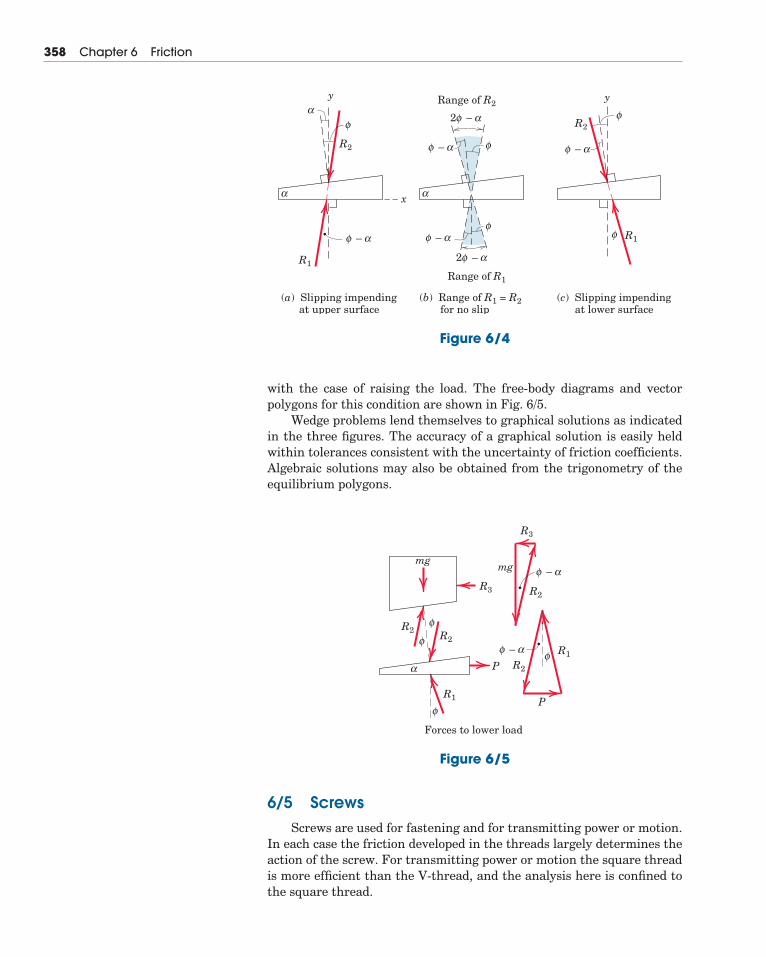
358 Chapter 6 Friction
with the case of raising the load. The free-body diagrams and vectorpolygons for this condition are shown in Fig. 6/5.
Wedge problems lend themselves to graphical solutions as indicatedin the three figures. The accuracy of a graphical solution is easily heldwithin tolerances consistent with the uncertainty of friction coefficients.Algebraic solutions may also be obtained from the trigonometry of theequilibrium polygons.
y
x
–
R1
R1
R2
y
R2
α
α
αφ
(a) Slipping impending at upper surface
(b) Range of R1 = R2 for no slip
φ
–
α
αφφ
– αφ
– αφ
φ
2
– αφ2
Range of R2
Range of R1
(c) Slipping impending at lower surface
α
φ
– αφ
φ
Figure 6/4
6/5 ScrewsScrews are used for fastening and for transmitting power or motion.
In each case the friction developed in the threads largely determines theaction of the screw. For transmitting power or motion the square threadis more efficient than the V-thread, and the analysis here is confined tothe square thread.
–R3
R2
R1
R2
R1R2
R2
R3
P
Forces to lower load
P
α
α
φ
– αφ φ
φ
φ
φ
mgmg
Figure 6/5
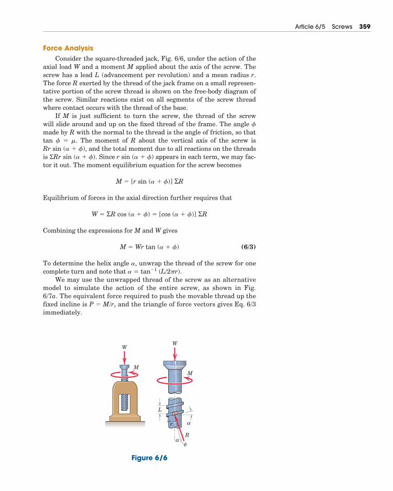
Force AnalysisConsider the square-threaded jack, Fig. 6/6, under the action of the
axial load W and a moment M applied about the axis of the screw. Thescrew has a lead L (advancement per revolution) and a mean radius r.The force R exerted by the thread of the jack frame on a small represen-tative portion of the screw thread is shown on the free-body diagram ofthe screw. Similar reactions exist on all segments of the screw threadwhere contact occurs with the thread of the base.
If M is just sufficient to turn the screw, the thread of the screw will slide around and up on the fixed thread of the frame. The angle �made by R with the normal to the thread is the angle of friction, so thattan � � �. The moment of R about the vertical axis of the screw is Rr sin (� � �), and the total moment due to all reactions on the threadsis ΣRr sin (� � �). Since r sin (� � �) appears in each term, we may fac-tor it out. The moment equilibrium equation for the screw becomes
Equilibrium of forces in the axial direction further requires that
Combining the expressions for M and W gives
(6/3)
To determine the helix angle �, unwrap the thread of the screw for onecomplete turn and note that � � tan�1 (L/2�r).
We may use the unwrapped thread of the screw as an alternativemodel to simulate the action of the entire screw, as shown in Fig.6/7a. The equivalent force required to push the movable thread up thefixed incline is P � M/r, and the triangle of force vectors gives Eq. 6/3immediately.
M � Wr tan (� � �)
W � ΣR cos (� � �) � [cos (� � �)] ΣR
M � [r sin (� � �)] ΣR
Article 6/5 Screws 359
WW
MM
φα
α
R
r
L
Figure 6/6
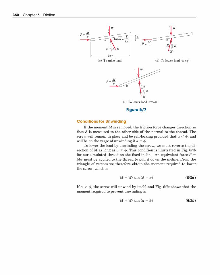
360 Chapter 6 Friction
Conditions for UnwindingIf the moment M is removed, the friction force changes direction so
that � is measured to the other side of the normal to the thread. Thescrew will remain in place and be self-locking provided that � � �, andwill be on the verge of unwinding if � � �.
To lower the load by unwinding the screw, we must reverse the di-rection of M as long as � � �. This condition is illustrated in Fig. 6/7bfor our simulated thread on the fixed incline. An equivalent force P �
M/r must be applied to the thread to pull it down the incline. From thetriangle of vectors we therefore obtain the moment required to lowerthe screw, which is
(6/3a)
If � � �, the screw will unwind by itself, and Fig. 6/7c shows that themoment required to prevent unwinding is
(6/3b)M � Wr tan (� � �)
M � Wr tan (� � �)
2
(a) To raise load
π r
2π r
L
W
R
α
α
α
φ
M––r
P =L–––tan =
(b) To lower load
W
R
α
α
α
φ
φ
M––r
P =
( < )
(c) To lower load
W
R
α
α
αφ
φ
M––r
P =
( > )
Figure 6/7
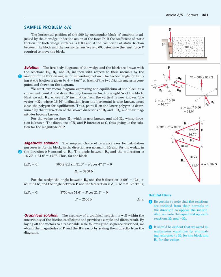
SAMPLE PROBLEM 6/6
The horizontal position of the 500-kg rectangular block of concrete is ad-justed by the 5� wedge under the action of the force P. If the coefficient of staticfriction for both wedge surfaces is 0.30 and if the coefficient of static frictionbetween the block and the horizontal surface is 0.60, determine the least force Prequired to move the block.
Solution. The free-body diagrams of the wedge and the block are drawn withthe reactions R1, R2, and R3 inclined with respect to their normals by theamount of the friction angles for impending motion. The friction angle for limit-ing static friction is given by � � tan�1 �. Each of the two friction angles is com-puted and shown on the diagram.
We start our vector diagram expressing the equilibrium of the block at aconvenient point A and draw the only known vector, the weight W of the block.Next we add R3, whose 31.0� inclination from the vertical is now known. Thevector �R2, whose 16.70� inclination from the horizontal is also known, mustclose the polygon for equilibrium. Thus, point B on the lower polygon is deter-mined by the intersection of the known directions of R3 and �R2, and their mag-nitudes become known.
For the wedge we draw R2, which is now known, and add R1, whose direc-tion is known. The directions of R1 and P intersect at C, thus giving us the solu-tion for the magnitude of P.
Algebraic solution. The simplest choice of reference axes for calculationpurposes is, for the block, in the direction a-a normal to R3 and, for the wedge, inthe direction b-b normal to R1. The angle between R2 and the a-direction is16.70� � 31.0� � 47.7�. Thus, for the block
For the wedge the angle between R2 and the b-direction is 90� � (2�1 �
5�) � 51.6�, and the angle between P and the b-direction is �1 � 5� � 21.7�. Thus,
Ans.
Graphical solution. The accuracy of a graphical solution is well within theuncertainty of the friction coefficients and provides a simple and direct result. Bylaying off the vectors to a reasonable scale following the sequence described, weobtain the magnitudes of P and the R’s easily by scaling them directly from thediagrams.
P � 2500 N
3750 cos 51.6� � P cos 21.7� � 0[ΣFb � 0]
R2 � 3750 N
500(9.81) sin 31.0� � R2 cos 47.7� � 0[ΣFa � 0]
Article 6/5 Screws 361
5°
P
500 kg
P
P
C
AB
R1
R1
R2
R3
–R2
R2
R3
–R2
b
ba
a
5°
1φ
1φ
1φ
2φ
1φW = 500(9.81) N
= tan–1 0.30= 16.70°
16.70°
16.70°
31.0°
2φ = tan–1 0.60= 31.0°
Wedge
Block
16.70° + 5° = 21.7°
W = 4905 N
�
�
Helpful Hints
� Be certain to note that the reactionsare inclined from their normals inthe direction to oppose the motion.Also, we note the equal and oppositereactions R2 and �R2.
� It should be evident that we avoid si-multaneous equations by eliminat-ing reference to R3 for the block andR1 for the wedge.
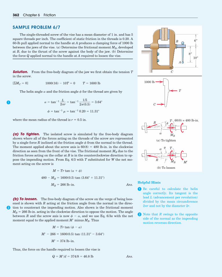
362 Chapter 6 Friction
SAMPLE PROBLEM 6/7
The single-threaded screw of the vise has a mean diameter of 1 in. and has 5square threads per inch. The coefficient of static friction in the threads is 0.20. A60-lb pull applied normal to the handle at A produces a clamping force of 1000 lbbetween the jaws of the vise. (a) Determine the frictional moment MB, developedat B, due to the thrust of the screw against the body of the jaw. (b) Determinethe force Q applied normal to the handle at A required to loosen the vise.
Solution. From the free-body diagram of the jaw we first obtain the tension Tin the screw.
The helix angle � and the friction angle � for the thread are given by
where the mean radius of the thread is r � 0.5 in.
(a) To tighten. The isolated screw is simulated by the free-body diagramshown where all of the forces acting on the threads of the screw are representedby a single force R inclined at the friction angle � from the normal to the thread.The moment applied about the screw axis is 60(8) � 480 lb-in. in the clockwisedirection as seen from the front of the vise. The frictional moment MB due to thefriction forces acting on the collar at B is in the counterclockwise direction to op-pose the impending motion. From Eq. 6/3 with T substituted for W the net mo-ment acting on the screw is
Ans.
(b) To loosen. The free-body diagram of the screw on the verge of being loos-ened is shown with R acting at the friction angle from the normal in the direc-tion to counteract the impending motion. Also shown is the frictional momentMB � 266 lb-in. acting in the clockwise direction to oppose the motion. The anglebetween R and the screw axis is now � � �, and we use Eq. 6/3a with the netmoment equal to the applied moment M� minus MB. Thus
Thus, the force on the handle required to loosen the vise is
Ans.Q � M�/d � 374/8 � 46.8 lb
M� � 374 lb-in.
M� � 266 � 1600(0.5) tan (11.31� � 3.64�)
M � Tr tan (� � �)
MB � 266 lb-in.
480 � MB � 1600(0.5) tan (3.64� � 11.31�)
M � Tr tan (� � �)
� � tan�1 � � tan�1 0.20 � 11.31�
� � tan�1 L2�r
� tan�1 1/52�(0.5)
� 3.64�
1000(16) � 10T � 0 T � 1600 lb[ΣMC � 0]
A
B
C
8′′10′′
6′′
1000 lb
C
T
α
φR60(8) = 480 lb-in.T
MB
(a) To tighten
α φ
R
T
MB M′
(b) To loosen
�
�
Helpful Hints
� Be careful to calculate the helixangle correctly. Its tangent is thelead L (advancement per revolution)divided by the mean circumference2�r and not by the diameter 2r.
� Note that R swings to the oppositeside of the normal as the impendingmotion reverses direction.
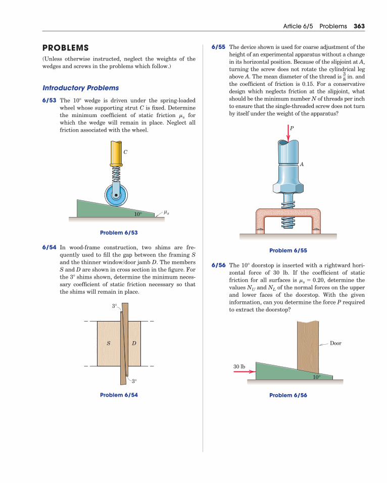
6/55 The device shown is used for coarse adjustment of theheight of an experimental apparatus without a changein its horizontal position. Because of the slipjoint at A,turning the screw does not rotate the cylindrical legabove A. The mean diameter of the thread is in. andthe coefficient of friction is 0.15. For a conservativedesign which neglects friction at the slipjoint, whatshould be the minimum number N of threads per inchto ensure that the single-threaded screw does not turnby itself under the weight of the apparatus?
Problem 6/55
6/56 The doorstop is inserted with a rightward hori-zontal force of 30 lb. If the coefficient of staticfriction for all surfaces is , determine thevalues and of the normal forces on the upperand lower faces of the doorstop. With the giveninformation, can you determine the force P requiredto extract the doorstop?
Problem 6/56
10∞
Door
30 lb
10°
NLNU
�s � 0.20
10�
P
A
38
Article 6/5 Problems 363
PROBLEMS(Unless otherwise instructed, neglect the weights of thewedges and screws in the problems which follow.)
Introductory Problems
6/53 The wedge is driven under the spring-loadedwheel whose supporting strut C is fixed. Determinethe minimum coefficient of static friction forwhich the wedge will remain in place. Neglect allfriction associated with the wheel.
Problem 6/53
6/54 In wood-frame construction, two shims are fre-quently used to fill the gap between the framing Sand the thinner window/door jamb D. The membersS and D are shown in cross section in the figure. Forthe shims shown, determine the minimum neces-sary coefficient of static friction necessary so thatthe shims will remain in place.
Problem 6/54
DS
3°
3°
3�
10°
C
sμ
�s
10�
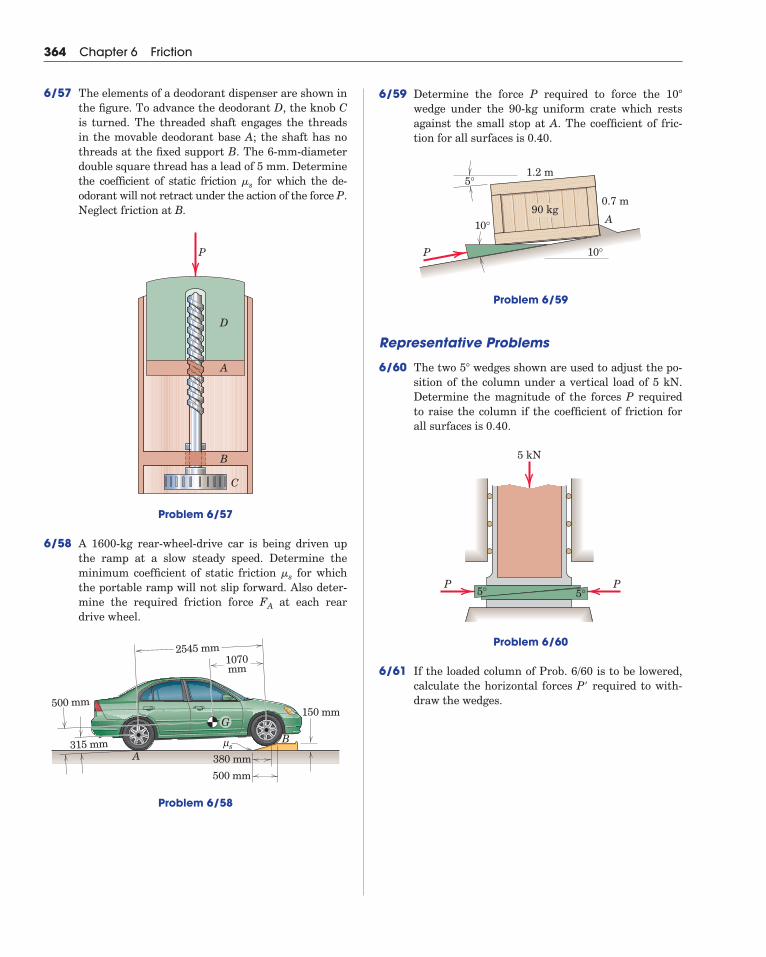
364 Chapter 6 Friction
6/57 The elements of a deodorant dispenser are shown inthe figure. To advance the deodorant D, the knob Cis turned. The threaded shaft engages the threadsin the movable deodorant base A; the shaft has nothreads at the fixed support B. The 6-mm-diameterdouble square thread has a lead of 5 mm. Determinethe coefficient of static friction for which the de-odorant will not retract under the action of the force P.Neglect friction at B.
Problem 6/57
6/58 A 1600-kg rear-wheel-drive car is being driven upthe ramp at a slow steady speed. Determine theminimum coefficient of static friction for whichthe portable ramp will not slip forward. Also deter-mine the required friction force at each reardrive wheel.
Problem 6/58
1070mm
315 mm
500 mm
2545 mm
150 mm
500 mm
Bsμ
380 mmA
G
FA
�s
P
D
A
B
C
�s
6/59 Determine the force P required to force the wedge under the 90-kg uniform crate which restsagainst the small stop at A. The coefficient of fric-tion for all surfaces is 0.40.
Problem 6/59
Representative Problems
6/60 The two wedges shown are used to adjust the po-sition of the column under a vertical load of 5 kN.Determine the magnitude of the forces P requiredto raise the column if the coefficient of friction forall surfaces is 0.40.
Problem 6/60
6/61 If the loaded column of Prob. 6/60 is to be lowered,calculate the horizontal forces P required to with-draw the wedges.
�
P P
5 kN
5° 5°
5�
P
0.7 m
A
1.2 m5°
10°
10°90 kg
10�
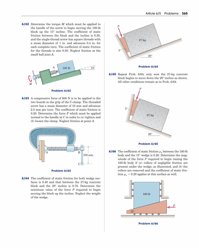
Problem 6/64
6/65 Repeat Prob. 6/64, only now the 27-kg concreteblock begins to move down the incline as shown.All other conditions remain as in Prob. 6/64.
Problem 6/65
6/66 The coefficient of static friction between the 100-lbbody and the wedge is 0.20. Determine the mag-nitude of the force P required to begin raising the100-lb body if (a) rollers of negligible friction arepresent under the wedge, as illustrated, and (b) therollers are removed and the coefficient of static fric-tion applies at this surface as well.
Problem 6/66
15°
100 lb
P
�s � 0.20
15�
�s
P
20°
5°
27 kg
20�
P
20°
5°
27 kg
Article 6/5 Problems 365
6/62 Determine the torque M which must be applied tothe handle of the screw to begin moving the 100-lbblock up the incline. The coefficient of staticfriction between the block and the incline is 0.50,and the single-thread screw has square threads witha mean diameter of 1 in. and advances 0.4 in. foreach complete turn. The coefficient of static frictionfor the threads is also 0.50. Neglect friction at thesmall ball joint A.
Problem 6/62
6/63 A compressive force of 600 N is to be applied to thetwo boards in the grip of the C-clamp. The threadedscrew has a mean diameter of 10 mm and advances2.5 mm per turn. The coefficient of static friction is0.20. Determine the force F which must be appliednormal to the handle at C in order to (a) tighten and(b) loosen the clamp. Neglect friction at point A.
Problem 6/63
6/64 The coefficient of static friction for both wedge sur-faces is 0.40 and that between the 27-kg concreteblock and the incline is 0.70. Determine theminimum value of the force P required to beginmoving the block up the incline. Neglect the weightof the wedge.
20�
A B
C
100 mm
M
A 15°100 lb
15�
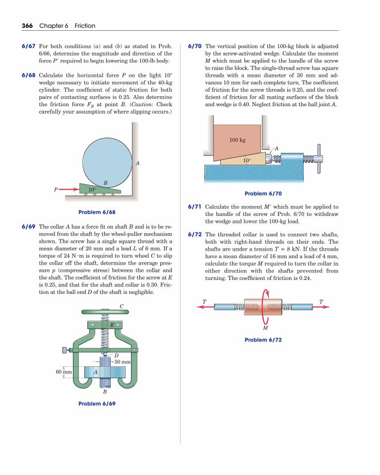
366 Chapter 6 Friction
6/67 For both conditions (a) and (b) as stated in Prob.6/66, determine the magnitude and direction of theforce P required to begin lowering the 100-lb body.
6/68 Calculate the horizontal force P on the light wedge necessary to initiate movement of the 40-kgcylinder. The coefficient of static friction for bothpairs of contacting surfaces is 0.25. Also determinethe friction force at point B. (Caution: Checkcarefully your assumption of where slipping occurs.)
Problem 6/68
6/69 The collar A has a force fit on shaft B and is to be re-moved from the shaft by the wheel-puller mechanismshown. The screw has a single square thread with amean diameter of 20 mm and a lead L of 6 mm. If atorque of 24 N m is required to turn wheel C to slipthe collar off the shaft, determine the average pres-sure p (compressive stress) between the collar andthe shaft. The coefficient of friction for the screw at Eis 0.25, and that for the shaft and collar is 0.30. Fric-tion at the ball end D of the shaft is negligible.
Problem 6/69
60 mm
50 mm
C
E
D
A
B
�
P 10°B
A
FB
10�
�
6/70 The vertical position of the 100-kg block is adjustedby the screw-activated wedge. Calculate the momentM which must be applied to the handle of the screwto raise the block. The single-thread screw has squarethreads with a mean diameter of 30 mm and ad-vances 10 mm for each complete turn. The coefficientof friction for the screw threads is 0.25, and the coef-ficient of friction for all mating surfaces of the blockand wedge is 0.40. Neglect friction at the ball joint A.
Problem 6/70
6/71 Calculate the moment M which must be applied tothe handle of the screw of Prob. 6/70 to withdrawthe wedge and lower the 100-kg load.
6/72 The threaded collar is used to connect two shafts,both with right-hand threads on their ends. Theshafts are under a tension T = 8 kN. If the threadshave a mean diameter of 16 mm and a lead of 4 mm,calculate the torque M required to turn the collar ineither direction with the shafts prevented fromturning. The coefficient of friction is 0.24.
Problem 6/72
M
TT
�
100 kg
10°
A
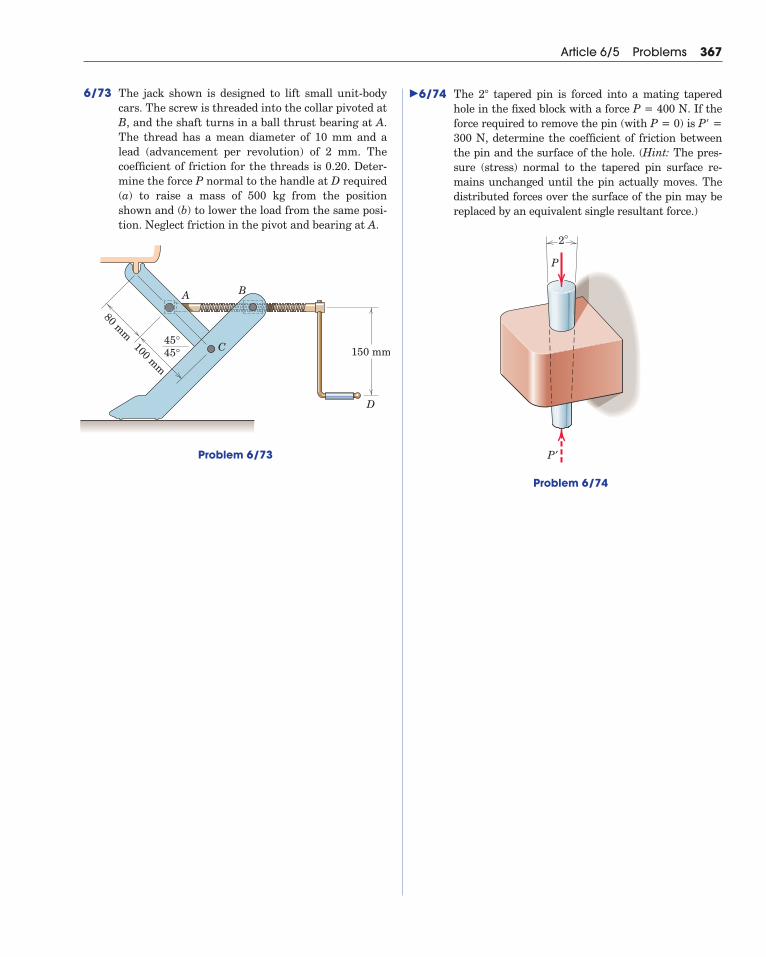
Article 6/5 Problems 367
6/73 The jack shown is designed to lift small unit-bodycars. The screw is threaded into the collar pivoted atB, and the shaft turns in a ball thrust bearing at A.The thread has a mean diameter of 10 mm and alead (advancement per revolution) of 2 mm. The coefficient of friction for the threads is 0.20. Deter-mine the force P normal to the handle at D required(a) to raise a mass of 500 kg from the positionshown and (b) to lower the load from the same posi-tion. Neglect friction in the pivot and bearing at A.
Problem 6/73
�
150 mm45°45°
100 mm
80 mm
D
C
BA
6/74 The tapered pin is forced into a mating taperedhole in the fixed block with a force P = 400 N. If theforce required to remove the pin (with P = 0) is P =300 N, determine the coefficient of friction betweenthe pin and the surface of the hole. (Hint: The pres-sure (stress) normal to the tapered pin surface re-mains unchanged until the pin actually moves. Thedistributed forces over the surface of the pin may bereplaced by an equivalent single resultant force.)
Problem 6/74
2°
P′
P
�
2�
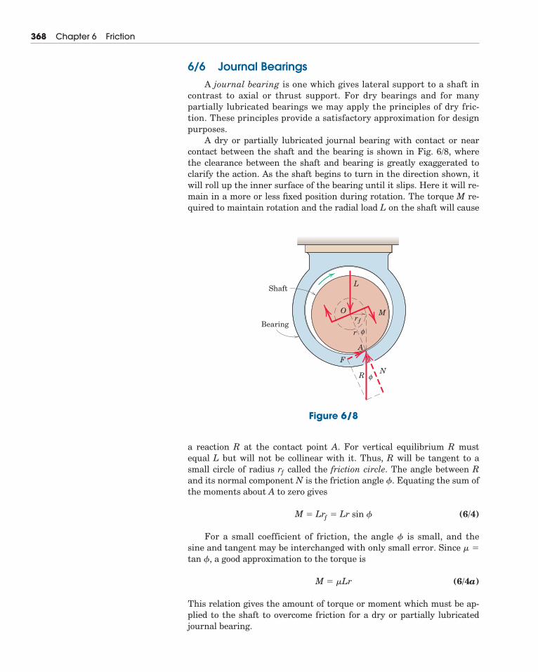
6/6 Journal BearingsA journal bearing is one which gives lateral support to a shaft in
contrast to axial or thrust support. For dry bearings and for manypartially lubricated bearings we may apply the principles of dry fric-tion. These principles provide a satisfactory approximation for designpurposes.
A dry or partially lubricated journal bearing with contact or nearcontact between the shaft and the bearing is shown in Fig. 6/8, wherethe clearance between the shaft and bearing is greatly exaggerated toclarify the action. As the shaft begins to turn in the direction shown, itwill roll up the inner surface of the bearing until it slips. Here it will re-main in a more or less fixed position during rotation. The torque M re-quired to maintain rotation and the radial load L on the shaft will cause
368 Chapter 6 Friction
a reaction R at the contact point A. For vertical equilibrium R mustequal L but will not be collinear with it. Thus, R will be tangent to asmall circle of radius rƒ called the friction circle. The angle between Rand its normal component N is the friction angle �. Equating the sum ofthe moments about A to zero gives
(6/4)
For a small coefficient of friction, the angle � is small, and thesine and tangent may be interchanged with only small error. Since � �
tan �, a good approximation to the torque is
(6/4a)
This relation gives the amount of torque or moment which must be ap-plied to the shaft to overcome friction for a dry or partially lubricatedjournal bearing.
M � �Lr
M � Lrƒ � Lr sin �
Shaft
Bearing
L
M
NR
F
A
Orƒ
r
Figure 6/8
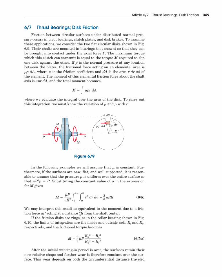
6/7 Thrust Bearings; Disk FrictionFriction between circular surfaces under distributed normal pres-
sure occurs in pivot bearings, clutch plates, and disk brakes. To examinethese applications, we consider the two flat circular disks shown in Fig.6/9. Their shafts are mounted in bearings (not shown) so that they canbe brought into contact under the axial force P. The maximum torquewhich this clutch can transmit is equal to the torque M required to slipone disk against the other. If p is the normal pressure at any locationbetween the plates, the frictional force acting on an elemental area is �p dA, where � is the friction coefficient and dA is the area r dr d� ofthe element. The moment of this elemental friction force about the shaftaxis is �pr dA, and the total moment becomes
where we evaluate the integral over the area of the disk. To carry outthis integration, we must know the variation of � and p with r.
M � � �pr dA
Article 6/7 Thrust Bearings; Disk Friction 369
dθ
R
p dAμ dr
P P
M
M
r
Figure 6/9
In the following examples we will assume that � is constant. Fur-thermore, if the surfaces are new, flat, and well supported, it is reason-able to assume that the pressure p is uniform over the entire surface sothat �R2p � P. Substituting the constant value of p in the expressionfor M gives
(6/5)
We may interpret this result as equivalent to the moment due to a fric-tion force �P acting at a distance from the shaft center.
If the friction disks are rings, as in the collar bearing shown in Fig.6/10, the limits of integration are the inside and outside radii Ri and Ro,respectively, and the frictional torque becomes
(6/5a)
After the initial wearing-in period is over, the surfaces retain theirnew relative shape and further wear is therefore constant over the sur-face. This wear depends on both the circumferential distance traveled
M �23
�PRo
3 � Ri
3
Ro
2 � Ri
2
23R
M ��P�R2 �
2�
0�R
0r2 dr d� �
23
�PR
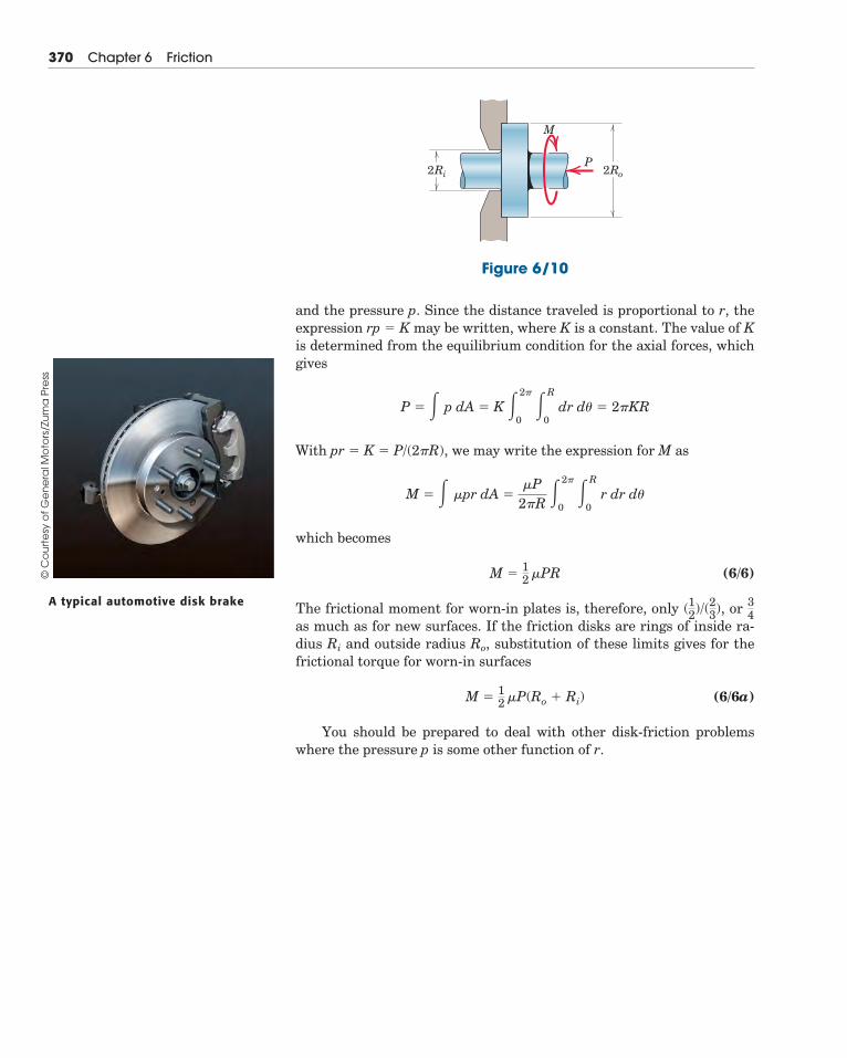
and the pressure p. Since the distance traveled is proportional to r, theexpression rp � K may be written, where K is a constant. The value of Kis determined from the equilibrium condition for the axial forces, whichgives
With pr � K � P/(2�R), we may write the expression for M as
which becomes
(6/6)
The frictional moment for worn-in plates is, therefore, only or as much as for new surfaces. If the friction disks are rings of inside ra-dius Ri and outside radius Ro, substitution of these limits gives for thefrictional torque for worn-in surfaces
(6/6a)
You should be prepared to deal with other disk-friction problemswhere the pressure p is some other function of r.
M �12
�P(Ro � Ri)
34(12)/(23),
M �12
�PR
M � � �pr dA ��P
2�R�2�
0�R
0r dr d�
P � � p dA � K �2�
0�R
0dr d� � 2�KR
370 Chapter 6 Friction
2Ri 2RoP
M
Figure 6/10
A typical automotive disk brake
© C
ou
rte
sy o
f G
en
era
l Mo
tors
/Zu
ma
Pre
ss
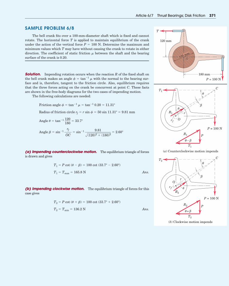
SAMPLE PROBLEM 6/8
The bell crank fits over a 100-mm-diameter shaft which is fixed and cannotrotate. The horizontal force T is applied to maintain equilibrium of the crankunder the action of the vertical force P � 100 N. Determine the maximum andminimum values which T may have without causing the crank to rotate in eitherdirection. The coefficient of static friction � between the shaft and the bearingsurface of the crank is 0.20.
Solution. Impending rotation occurs when the reaction R of the fixed shaft onthe bell crank makes an angle � � tan�1 � with the normal to the bearing sur-face and is, therefore, tangent to the friction circle. Also, equilibrium requiresthat the three forces acting on the crank be concurrent at point C. These factsare shown in the free-body diagrams for the two cases of impending motion.
The following calculations are needed:
(a) Impending counterclockwise motion. The equilibrium triangle of forcesis drawn and gives
Ans.
(b) Impending clockwise motion. The equilibrium triangle of forces for thiscase gives
Ans.T2 � Tmin � 136.2 N
T2 � P cot (� � �) � 100 cot (33.7� � 2.60�)
T1 � Tmax � 165.8 N
T1 � P cot (� � �) � 100 cot (33.7� � 2.60�)
Angle � � sin�1rƒ
OC� sin�1 9.81
�(120)2 � (180)2� 2.60�
Angle � � tan�1 120180
� 33.7�
Radius of friction circle rƒ � r sin � � 50 sin 11.31� � 9.81 mm
Friction angle � � tan�1 � � tan�1 0.20 � 11.31�
Article 6/7 Thrust Bearings; Disk Friction 371
P = 100 N
180 mm
120 mm
T
100 mm
O
P = 100 N
P
O
T1
R1
R1
T1
–
C
r
rƒ
(a) Counterclockwise motion impends
P = 100 N
PR2
T2
+
(b) Clockwise motion impends
O
T2
R2
C
r
rƒ
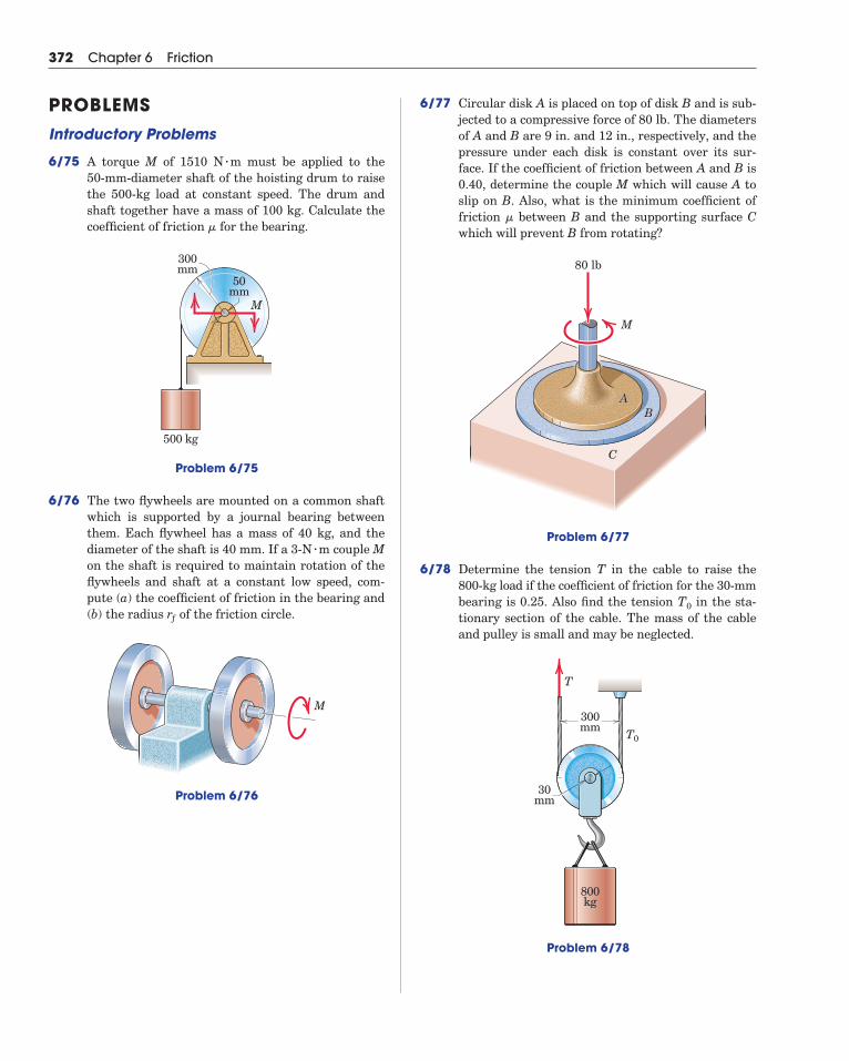
6/77 Circular disk A is placed on top of disk B and is sub-jected to a compressive force of 80 lb. The diametersof A and B are 9 in. and 12 in., respectively, and thepressure under each disk is constant over its sur-face. If the coefficient of friction between A and B is0.40, determine the couple M which will cause A toslip on B. Also, what is the minimum coefficient offriction between B and the supporting surface Cwhich will prevent B from rotating?
Problem 6/77
6/78 Determine the tension T in the cable to raise the800-kg load if the coefficient of friction for the 30-mmbearing is 0.25. Also find the tension in the sta-tionary section of the cable. The mass of the cableand pulley is small and may be neglected.
Problem 6/78
300mm
30mm
T
T0
800kg
T0
AABB
C
M
80 lb
�
372 Chapter 6 Friction
PROBLEMSIntroductory Problems
6/75 A torque M of 1510 N m must be applied to the 50-mm-diameter shaft of the hoisting drum to raisethe 500-kg load at constant speed. The drum andshaft together have a mass of 100 kg. Calculate thecoefficient of friction for the bearing.
Problem 6/75
6/76 The two flywheels are mounted on a common shaftwhich is supported by a journal bearing betweenthem. Each flywheel has a mass of 40 kg, and thediameter of the shaft is 40 mm. If a 3-N m couple Mon the shaft is required to maintain rotation of theflywheels and shaft at a constant low speed, com-pute (a) the coefficient of friction in the bearing and(b) the radius rƒ of the friction circle.
Problem 6/76
M
�
500 kg
50mm
300mm
M
�
�
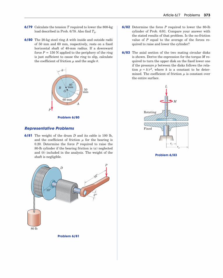
6/79 Calculate the tension T required to lower the 800-kgload described in Prob. 6/78. Also find .
6/80 The 20-kg steel ring A with inside and outside radiiof 50 mm and 60 mm, respectively, rests on a fixedhorizontal shaft of 40-mm radius. If a downwardforce P = 150 N applied to the periphery of the ringis just sufficient to cause the ring to slip, calculatethe coefficient of friction and the angle .
Problem 6/80
Representative Problems
6/81 The weight of the drum D and its cable is 100 lb,and the coefficient of friction for the bearing is0.20. Determine the force P required to raise the 80-lb cylinder if the bearing friction is (a) neglectedand (b) included in the analysis. The weight of theshaft is negligible.
Problem 6/81
16′′
2′′
10′′
80 lb
DP
�
40mm
50mm
60 mm
BG
A
P
θ
��
T0
Article 6/7 Problems 373
6/82 Determine the force P required to lower the 80-lbcylinder of Prob. 6/81. Compare your answer withthe stated results of that problem. Is the no-frictionvalue of P equal to the average of the forces re-quired to raise and lower the cylinder?
6/83 The axial section of the two mating circular disksis shown. Derive the expression for the torque M re-quired to turn the upper disk on the fixed lower oneif the pressure p between the disks follows the rela-tion , where k is a constant to be deter-mined. The coefficient of friction is constant overthe entire surface.
Problem 6/83
Rotating
Fixed
ri
M
L
ro
�
p � k/r2
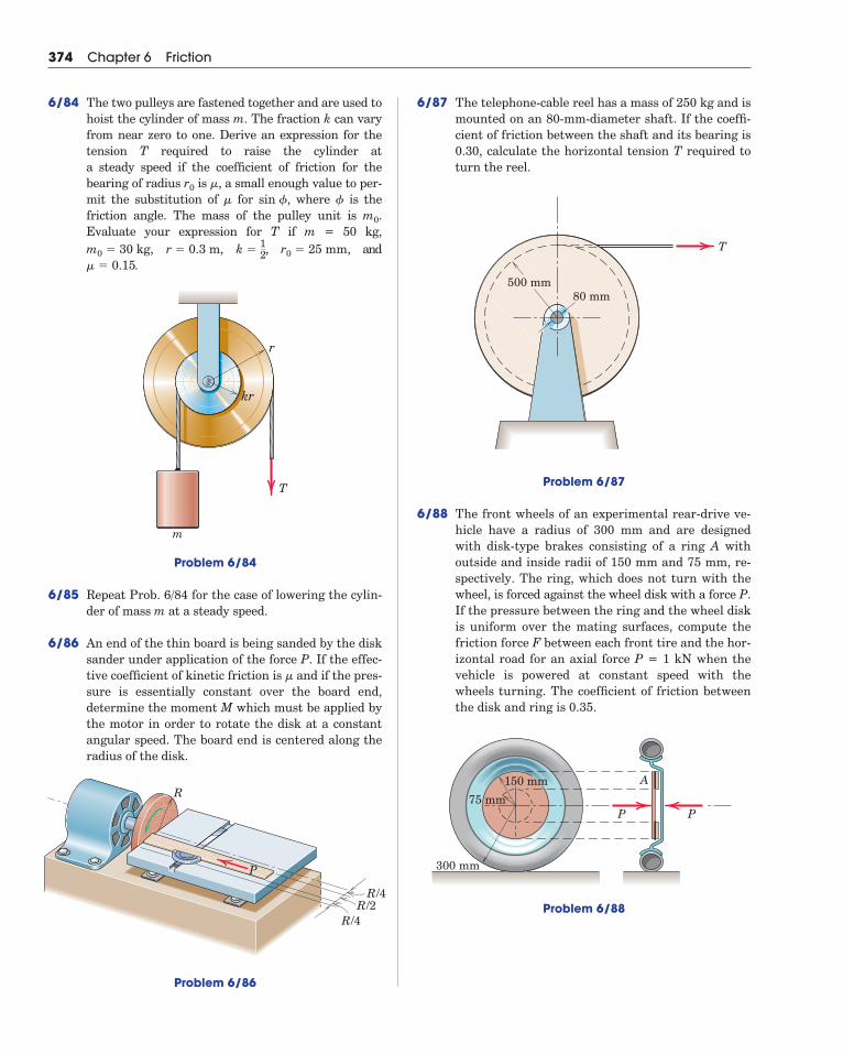
6/87 The telephone-cable reel has a mass of 250 kg and ismounted on an 80-mm-diameter shaft. If the coeffi-cient of friction between the shaft and its bearing is0.30, calculate the horizontal tension T required toturn the reel.
Problem 6/87
6/88 The front wheels of an experimental rear-drive ve-hicle have a radius of 300 mm and are designedwith disk-type brakes consisting of a ring A withoutside and inside radii of 150 mm and 75 mm, re-spectively. The ring, which does not turn with thewheel, is forced against the wheel disk with a force P.If the pressure between the ring and the wheel diskis uniform over the mating surfaces, compute thefriction force F between each front tire and the hor-izontal road for an axial force P = 1 kN when thevehicle is powered at constant speed with thewheels turning. The coefficient of friction betweenthe disk and ring is 0.35.
Problem 6/88
A
P P75 mm
300 mm
150 mm
500 mm80 mm
T
374 Chapter 6 Friction
6/84 The two pulleys are fastened together and are used tohoist the cylinder of mass m. The fraction k can varyfrom near zero to one. Derive an expression for thetension T required to raise the cylinder at a steady speed if the coefficient of friction for thebearing of radius is , a small enough value to per-mit the substitution of for , where is thefriction angle. The mass of the pulley unit is .Evaluate your expression for T if m = 50 kg,
, and.
Problem 6/84
6/85 Repeat Prob. 6/84 for the case of lowering the cylin-der of mass m at a steady speed.
6/86 An end of the thin board is being sanded by the disksander under application of the force P. If the effec-tive coefficient of kinetic friction is and if the pres-sure is essentially constant over the board end,determine the moment M which must be applied bythe motor in order to rotate the disk at a constantangular speed. The board end is centered along theradius of the disk.
Problem 6/86
�
kr
r
T
m
� � 0.15r0 � 25 mm,k �
12r � 0.3 m,m0 � 30 kg,
m0
�sin ��
�r0
R/4R/2
R/4
R
P
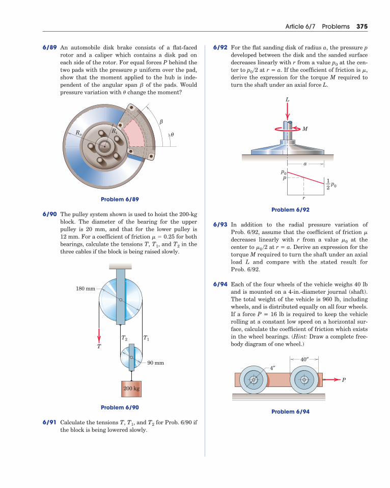
6/89 An automobile disk brake consists of a flat-facedrotor and a caliper which contains a disk pad oneach side of the rotor. For equal forces P behind thetwo pads with the pressure p uniform over the pad,show that the moment applied to the hub is inde-pendent of the angular span of the pads. Wouldpressure variation with change the moment?
Problem 6/89
6/90 The pulley system shown is used to hoist the 200-kgblock. The diameter of the bearing for the upperpulley is 20 mm, and that for the lower pulley is 12 mm. For a coefficient of friction for bothbearings, calculate the tensions T, , and in thethree cables if the block is being raised slowly.
Problem 6/90
6/91 Calculate the tensions T, , and for Prob. 6/90 ifthe block is being lowered slowly.
T2T1
180 mm
90 mm
200 kg
T1T2
T
T2T1
� � 0.25
RoRi
β
θ
�
�
Article 6/7 Problems 375
6/92 For the flat sanding disk of radius a, the pressure pdeveloped between the disk and the sanded surfacedecreases linearly with r from a value at the cen-ter to at r = a. If the coefficient of friction is ,derive the expression for the torque M required toturn the shaft under an axial force L.
Problem 6/92
6/93 In addition to the radial pressure variation of Prob. 6/92, assume that the coefficient of friction decreases linearly with r from a value at thecenter to at r = a. Derive an expression for thetorque M required to turn the shaft under an axialload L and compare with the stated result forProb. 6/92.
6/94 Each of the four wheels of the vehicle weighs 40 lband is mounted on a 4-in.-diameter journal (shaft).The total weight of the vehicle is 960 lb, includingwheels, and is distributed equally on all four wheels.If a force P = 16 lb is required to keep the vehiclerolling at a constant low speed on a horizontal sur-face, calculate the coefficient of friction which existsin the wheel bearings. (Hint: Draw a complete free-body diagram of one wheel.)
Problem 6/94
P
40″4″
�0 /2�0
�
ap0
p0
p
M
L
r
1––2
�p0 /2p0
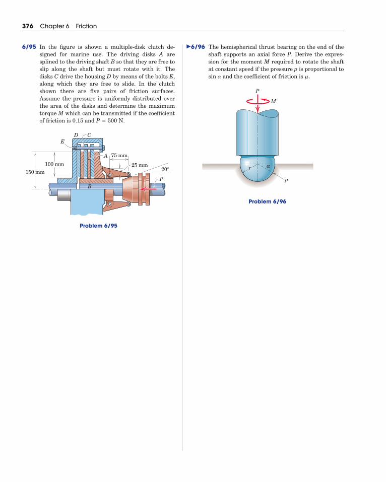
6/96 The hemispherical thrust bearing on the end of theshaft supports an axial force P. Derive the expres-sion for the moment M required to rotate the shaftat constant speed if the pressure p is proportional tosin and the coefficient of friction is .
Problem 6/96
r
P
M
α
p
��
376 Chapter 6 Friction
6/95 In the figure is shown a multiple-disk clutch de-signed for marine use. The driving disks A aresplined to the driving shaft B so that they are free toslip along the shaft but must rotate with it. Thedisks C drive the housing D by means of the bolts E,along which they are free to slide. In the clutchshown there are five pairs of friction surfaces.Assume the pressure is uniformly distributed overthe area of the disks and determine the maximumtorque M which can be transmitted if the coefficientof friction is 0.15 and P = 500 N.
Problem 6/95
75 mm
100 mm150 mm 20°
PB
A
DE
C
25 mm
�
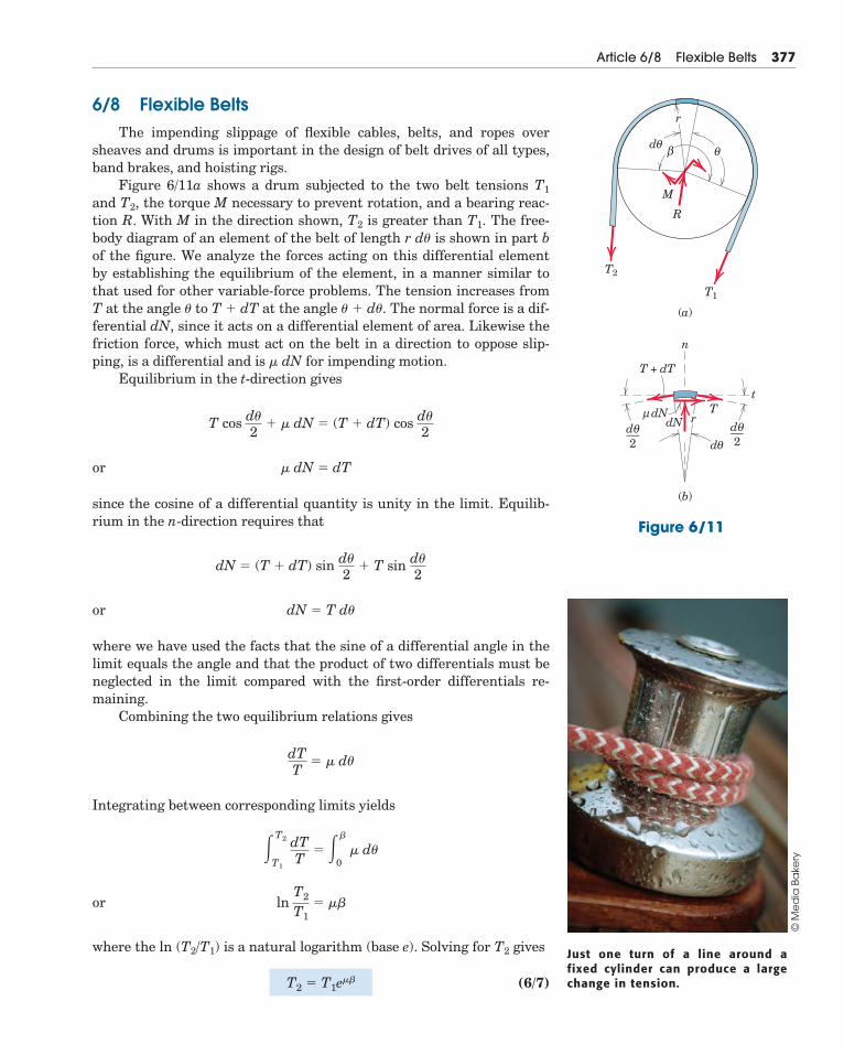
6/8 Flexible BeltsThe impending slippage of flexible cables, belts, and ropes over
sheaves and drums is important in the design of belt drives of all types,band brakes, and hoisting rigs.
Figure 6/11a shows a drum subjected to the two belt tensions T1
and T2, the torque M necessary to prevent rotation, and a bearing reac-tion R. With M in the direction shown, T2 is greater than T1. The free-body diagram of an element of the belt of length r d� is shown in part bof the figure. We analyze the forces acting on this differential elementby establishing the equilibrium of the element, in a manner similar tothat used for other variable-force problems. The tension increases fromT at the angle � to T � dT at the angle � � d�. The normal force is a dif-ferential dN, since it acts on a differential element of area. Likewise thefriction force, which must act on the belt in a direction to oppose slip-ping, is a differential and is � dN for impending motion.
Equilibrium in the t-direction gives
or
since the cosine of a differential quantity is unity in the limit. Equilib-rium in the n-direction requires that
or
where we have used the facts that the sine of a differential angle in thelimit equals the angle and that the product of two differentials must beneglected in the limit compared with the first-order differentials re-maining.
Combining the two equilibrium relations gives
Integrating between corresponding limits yields
or
where the ln (T2/T1) is a natural logarithm (base e). Solving for T2 gives
(6/7)T2 � T1e��
lnT2
T1� ��
�T2
T1
dTT
� ��
0� d�
dTT
� � d�
dN � T d�
dN � (T � dT) sin d�2
� T sin d�2
� dN � dT
T cos d�2
� � dN � (T � dT) cos d�2
Article 6/8 Flexible Belts 377
Figure 6/11
T2
T1
β θθd
θθ
d
μ rdNdN
r
M
R
(a)
(b)
T
T + dT
t
n
d––2
θd––2
Just one turn of a line around afixed cylinder can produce a largechange in tension.
© M
ed
ia B
ake
ry
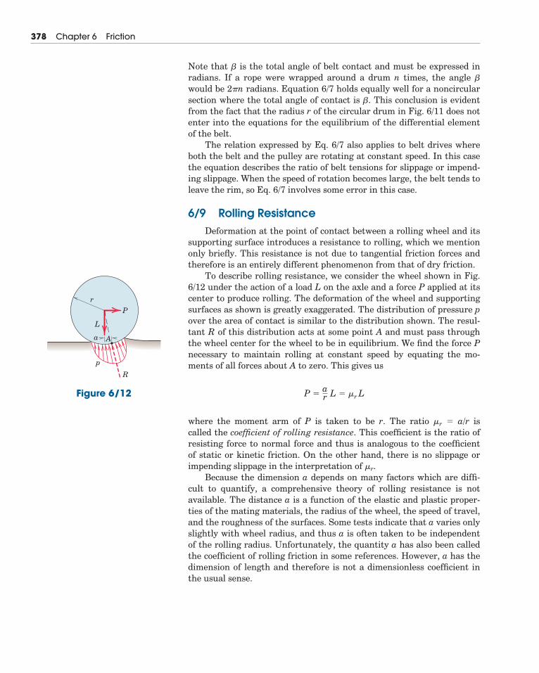
Note that � is the total angle of belt contact and must be expressed inradians. If a rope were wrapped around a drum n times, the angle �
would be 2�n radians. Equation 6/7 holds equally well for a noncircularsection where the total angle of contact is �. This conclusion is evidentfrom the fact that the radius r of the circular drum in Fig. 6/11 does notenter into the equations for the equilibrium of the differential elementof the belt.
The relation expressed by Eq. 6/7 also applies to belt drives whereboth the belt and the pulley are rotating at constant speed. In this casethe equation describes the ratio of belt tensions for slippage or impend-ing slippage. When the speed of rotation becomes large, the belt tends toleave the rim, so Eq. 6/7 involves some error in this case.
6/9 Rolling ResistanceDeformation at the point of contact between a rolling wheel and its
supporting surface introduces a resistance to rolling, which we mentiononly briefly. This resistance is not due to tangential friction forces andtherefore is an entirely different phenomenon from that of dry friction.
To describe rolling resistance, we consider the wheel shown in Fig.6/12 under the action of a load L on the axle and a force P applied at itscenter to produce rolling. The deformation of the wheel and supportingsurfaces as shown is greatly exaggerated. The distribution of pressure pover the area of contact is similar to the distribution shown. The resul-tant R of this distribution acts at some point A and must pass throughthe wheel center for the wheel to be in equilibrium. We find the force Pnecessary to maintain rolling at constant speed by equating the mo-ments of all forces about A to zero. This gives us
where the moment arm of P is taken to be r. The ratio �r � a/r iscalled the coefficient of rolling resistance. This coefficient is the ratio ofresisting force to normal force and thus is analogous to the coefficient of static or kinetic friction. On the other hand, there is no slippage orimpending slippage in the interpretation of �r.
Because the dimension a depends on many factors which are diffi-cult to quantify, a comprehensive theory of rolling resistance is notavailable. The distance a is a function of the elastic and plastic proper-ties of the mating materials, the radius of the wheel, the speed of travel,and the roughness of the surfaces. Some tests indicate that a varies onlyslightly with wheel radius, and thus a is often taken to be independentof the rolling radius. Unfortunately, the quantity a has also been calledthe coefficient of rolling friction in some references. However, a has thedimension of length and therefore is not a dimensionless coefficient inthe usual sense.
P �ar L � �r L
378 Chapter 6 Friction
R
p
a
r
A
L
P
Figure 6/12
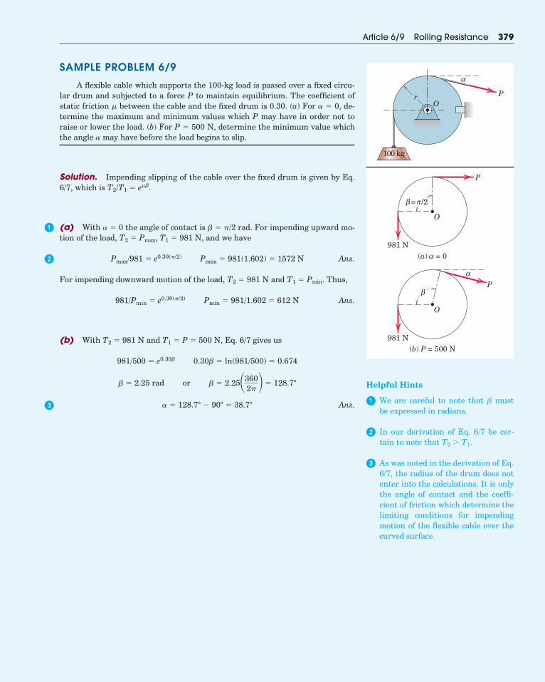
SAMPLE PROBLEM 6/9
A flexible cable which supports the 100-kg load is passed over a fixed circu-lar drum and subjected to a force P to maintain equilibrium. The coefficient ofstatic friction � between the cable and the fixed drum is 0.30. (a) For � � 0, de-termine the maximum and minimum values which P may have in order not toraise or lower the load. (b) For P � 500 N, determine the minimum value whichthe angle � may have before the load begins to slip.
Solution. Impending slipping of the cable over the fixed drum is given by Eq.6/7, which is T2/T1 � e��.
(a) With � � 0 the angle of contact is � � �/2 rad. For impending upward mo-tion of the load, T2 � Pmax, T1 � 981 N, and we have
Ans.
For impending downward motion of the load, T2 � 981 N and T1 � Pmin. Thus,
Ans.
(b) With T2 � 981 N and T1 � P � 500 N, Eq. 6/7 gives us
Ans.� � 128.7� � 90� � 38.7�
� � 2.25 rad or � � 2.25�3602� � 128.7�
981/500 � e0.30� 0.30� � ln(981/500) � 0.674
981/Pmin � e0.30(�/2) Pmin � 981/1.602 � 612 N
Pmax/981 � e0.30(�/2) Pmax � 981(1.602) � 1572 N
Article 6/9 Rolling Resistance 379
Or
α
P
100 kg
O
P
981 N(a) = 0α
= /2πβ
O
αP
981 N(b) P = 500 N
β
�
�
�
Helpful Hints
� We are careful to note that � mustbe expressed in radians.
� In our derivation of Eq. 6/7 be cer-tain to note that T2 � T1.
� As was noted in the derivation of Eq.6/7, the radius of the drum does notenter into the calculations. It is onlythe angle of contact and the coeffi-cient of friction which determine thelimiting conditions for impendingmotion of the flexible cable over thecurved surface.
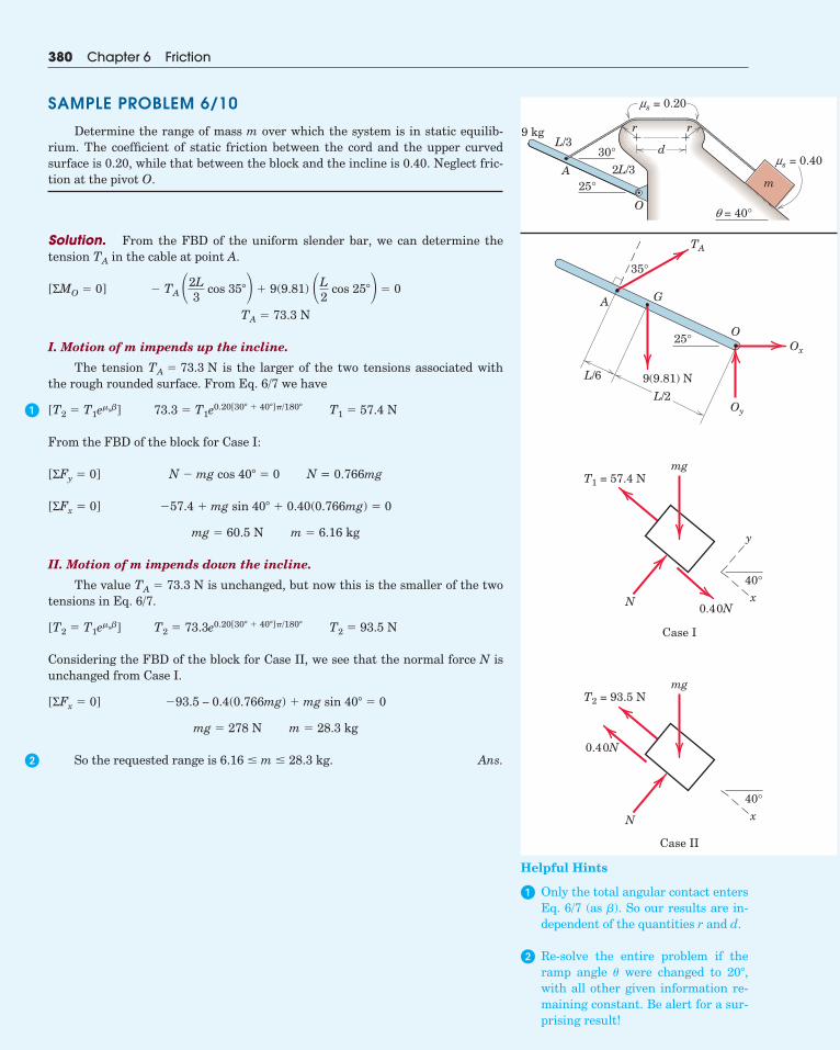
SAMPLE PROBLEM 6/10
Determine the range of mass m over which the system is in static equilib-rium. The coefficient of static friction between the cord and the upper curvedsurface is 0.20, while that between the block and the incline is 0.40. Neglect fric-tion at the pivot O.
Solution. From the FBD of the uniform slender bar, we can determine thetension in the cable at point A.
I. Motion of m impends up the incline.
The tension is the larger of the two tensions associated withthe rough rounded surface. From Eq. 6/7 we have
From the FBD of the block for Case I:
N = 0.766mg
II. Motion of m impends down the incline.
The value is unchanged, but now this is the smaller of the twotensions in Eq. 6/7.
Considering the FBD of the block for Case II, we see that the normal force N isunchanged from Case I.
So the requested range is . Ans.6.16 � m � 28.3 kg
m � 28.3 kgmg � 278 N
�93.5 – 0.4(0.766mg) � mg sin 40� � 0[ΣFx � 0]
T2 � 93.5 NT2 � 73.3e0.20[30� � 40�]�/180�[T2 � T1e�s�]
TA � 73.3 N
m � 6.16 kgmg � 60.5 N
�57.4 � mg sin 40� � 0.40(0.766mg) � 0[ΣFx � 0]
N � mg cos 40� � 0[ΣFy � 0]
T1 � 57.4 N73.3 � T1e0.20[30� � 40�]�/180�[T2 � T1e�s�]
TA � 73.3 N
TA � 73.3 N
� TA �2L3
cos 35� � 9(9.81) �L2
cos 25� � 0[ΣMO � 0]
TA
380 Chapter 6 Friction
r r
d30°
9 kg
25°A
O
m2L/3
L/3
ms = 0.20
ms = 0.40
q = 40°
40°
y
x
T1 = 57.4 N
N
Case I
0.40N
mg
40°x
T2 = 93.5 N
N
Case II
0.40N
mg
A
9(9.81) N
G
TA
Ox
Oy
O25°
35°
L/2
L/6
Helpful Hints
� Only the total angular contact entersEq. 6/7 (as ). So our results are in-dependent of the quantities r and d.
� Re-solve the entire problem if theramp angle were changed to ,with all other given information re-maining constant. Be alert for a sur-prising result!
20��
�
�
�
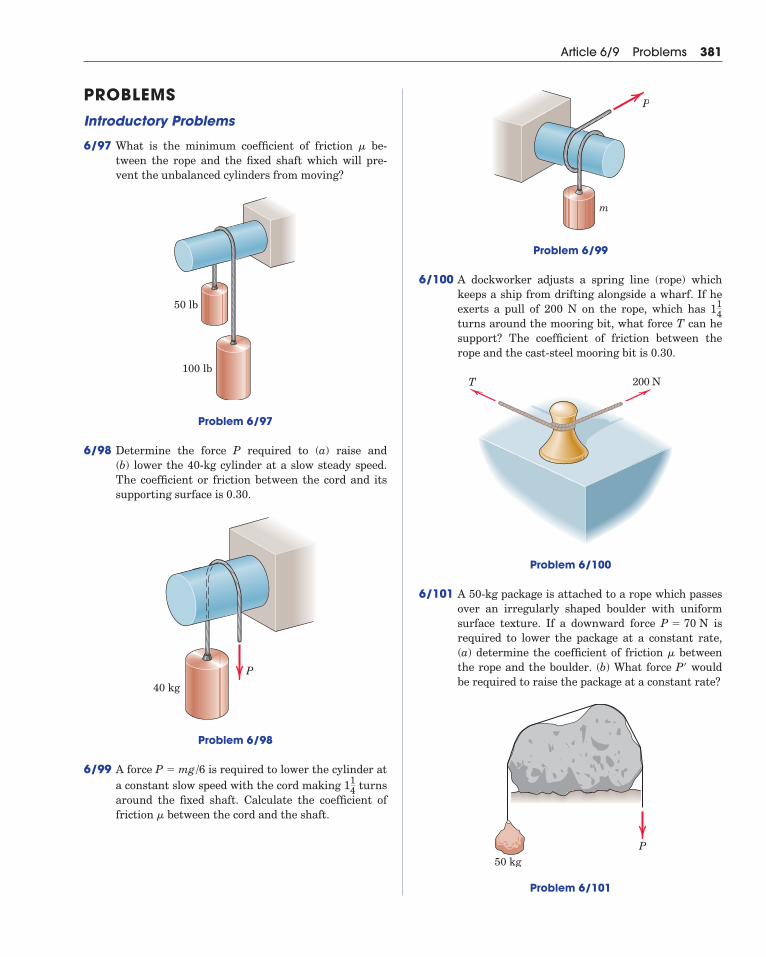
PROBLEMSIntroductory Problems
6/97 What is the minimum coefficient of friction be-tween the rope and the fixed shaft which will pre-vent the unbalanced cylinders from moving?
Problem 6/97
6/98 Determine the force P required to (a) raise and (b) lower the 40-kg cylinder at a slow steady speed.The coefficient or friction between the cord and itssupporting surface is 0.30.
Problem 6/98
6/99 A force is required to lower the cylinder ata constant slow speed with the cord making turnsaround the fixed shaft. Calculate the coefficient offriction between the cord and the shaft.�
114
P � mg/6
40 kg
P
50 lb
100 lb
�
Article 6/9 Problems 381
Problem 6/99
6/100 A dockworker adjusts a spring line (rope) whichkeeps a ship from drifting alongside a wharf. If heexerts a pull of 200 N on the rope, which has turns around the mooring bit, what force T can hesupport? The coefficient of friction between therope and the cast-steel mooring bit is 0.30.
Problem 6/100
6/101 A 50-kg package is attached to a rope which passesover an irregularly shaped boulder with uniformsurface texture. If a downward force isrequired to lower the package at a constant rate,(a) determine the coefficient of friction betweenthe rope and the boulder. (b) What force P wouldbe required to raise the package at a constant rate?
Problem 6/101
P50 kg
��
P � 70 N
200 NT
114
m
P
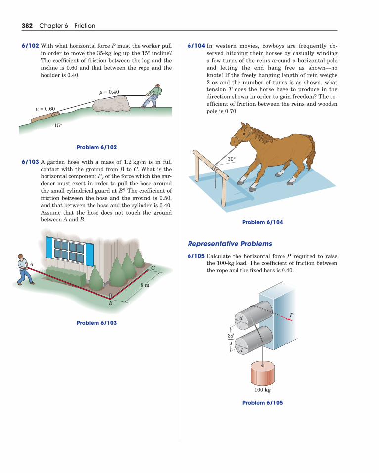
6/104 In western movies, cowboys are frequently ob-served hitching their horses by casually windinga few turns of the reins around a horizontal poleand letting the end hang free as shown––noknots! If the freely hanging length of rein weighs2 oz and the number of turns is as shown, whattension T does the horse have to produce in thedirection shown in order to gain freedom? The co-efficient of friction between the reins and woodenpole is 0.70.
Problem 6/104
Representative Problems
6/105 Calculate the horizontal force P required to raisethe 100-kg load. The coefficient of friction betweenthe rope and the fixed bars is 0.40.
Problem 6/105
d
P
100 kg
d
3d—2
30°
382 Chapter 6 Friction
6/102 With what horizontal force P must the worker pullin order to move the 35-kg log up the incline?The coefficient of friction between the log and theincline is 0.60 and that between the rope and theboulder is 0.40.
15�
15°
= 0.60μ
= 0.40μ
Problem 6/102
6/103 A garden hose with a mass of is in fullcontact with the ground from B to C. What is thehorizontal component of the force which the gar-dener must exert in order to pull the hose aroundthe small cylindrical guard at B? The coefficient offriction between the hose and the ground is 0.50,and that between the hose and the cylinder is 0.40.Assume that the hose does not touch the groundbetween A and B.
Problem 6/103
Px
1.2 kg /m
5 m
B
AC
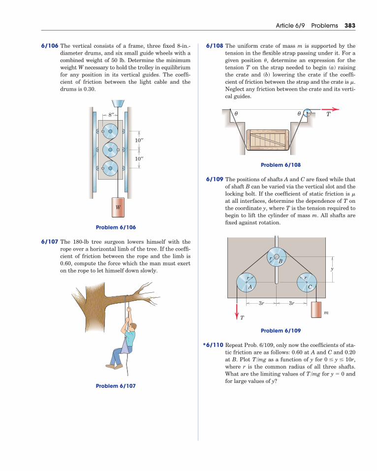
6/106 The vertical consists of a frame, three fixed 8-in.-diameter drums, and six small guide wheels with acombined weight of 50 lb. Determine the minimumweight W necessary to hold the trolley in equilibriumfor any position in its vertical guides. The coeffi-cient of friction between the light cable and thedrums is 0.30.
Problem 6/106
6/107 The 180-lb tree surgeon lowers himself with therope over a horizontal limb of the tree. If the coeffi-cient of friction between the rope and the limb is0.60, compute the force which the man must exerton the rope to let himself down slowly.
Problem 6/107
10′′
10′′
8′′
W
Article 6/9 Problems 383
6/108 The uniform crate of mass m is supported by thetension in the flexible strap passing under it. For agiven position , determine an expression for thetension T on the strap needed to begin (a) raisingthe crate and (b) lowering the crate if the coeffi-cient of friction between the strap and the crate is .Neglect any friction between the crate and its verti-cal guides.
Problem 6/108
6/109 The positions of shafts A and C are fixed while thatof shaft B can be varied via the vertical slot and thelocking bolt. If the coefficient of static friction is at all interfaces, determine the dependence of T onthe coordinate y, where T is the tension required tobegin to lift the cylinder of mass m. All shafts arefixed against rotation.
Problem 6/109
6/110 Repeat Prob. 6/109, only now the coefficients of sta-tic friction are as follows: 0.60 at A and C and 0.20at B. Plot as a function of y for ,where r is the common radius of all three shafts.What are the limiting values of for andfor large values of y?
y � 0T/mg
0 � y � 10rT/mg
r
3r
y
3r
r
r
C
B
A
mT
�
θ θ T
�
�
*
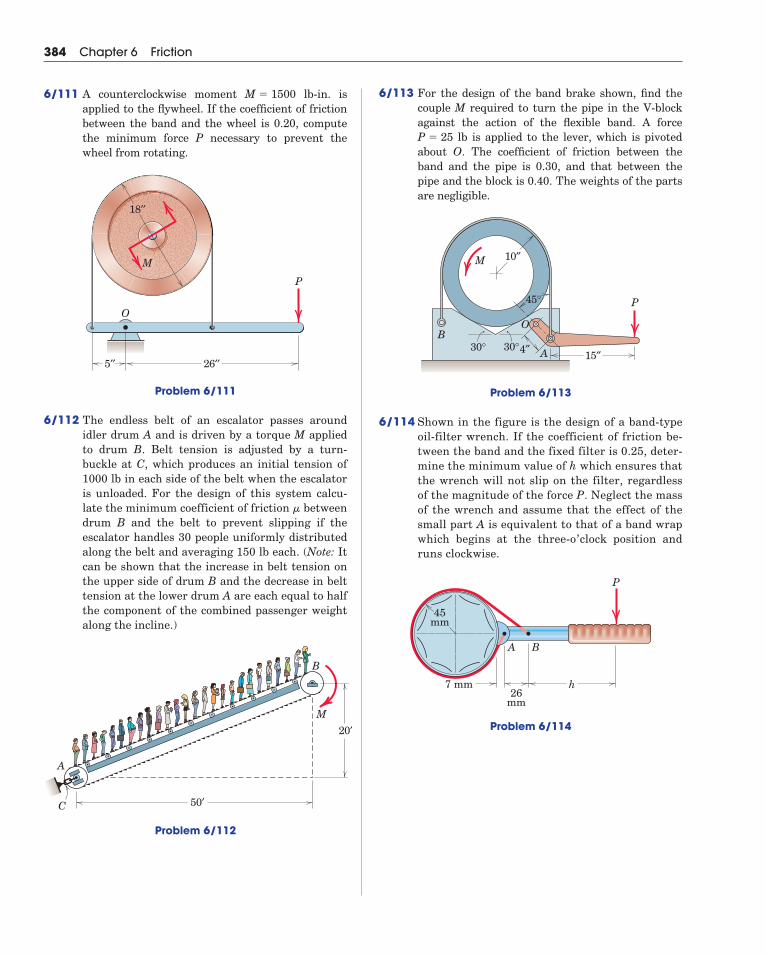
6/113 For the design of the band brake shown, find thecouple M required to turn the pipe in the V-blockagainst the action of the flexible band. A force
lb is applied to the lever, which is pivotedabout O. The coefficient of friction between theband and the pipe is 0.30, and that between thepipe and the block is 0.40. The weights of the partsare negligible.
Problem 6/113
6/114 Shown in the figure is the design of a band-typeoil-filter wrench. If the coefficient of friction be-tween the band and the fixed filter is 0.25, deter-mine the minimum value of h which ensures thatthe wrench will not slip on the filter, regardlessof the magnitude of the force P. Neglect the massof the wrench and assume that the effect of thesmall part A is equivalent to that of a band wrapwhich begins at the three-o’clock position andruns clockwise.
Problem 6/114
7 mm26
mm
h
A B
45mm
P
10″
4″30°30°
M
B
A
P
15″
45°
O
P � 25
384 Chapter 6 Friction
6/111 A counterclockwise moment lb-in. is applied to the flywheel. If the coefficient of frictionbetween the band and the wheel is 0.20, computethe minimum force P necessary to prevent thewheel from rotating.
Problem 6/111
6/112 The endless belt of an escalator passes aroundidler drum A and is driven by a torque M appliedto drum B. Belt tension is adjusted by a turn-buckle at C, which produces an initial tension of1000 lb in each side of the belt when the escalatoris unloaded. For the design of this system calcu-late the minimum coefficient of friction betweendrum B and the belt to prevent slipping if the escalator handles 30 people uniformly distributedalong the belt and averaging 150 lb each. (Note: Itcan be shown that the increase in belt tension onthe upper side of drum B and the decrease in belttension at the lower drum A are each equal to halfthe component of the combined passenger weightalong the incline.)
Problem 6/112
�
P
O
26′′5′′
18′′
M
M � 1500
20′
50′C
A
B
M
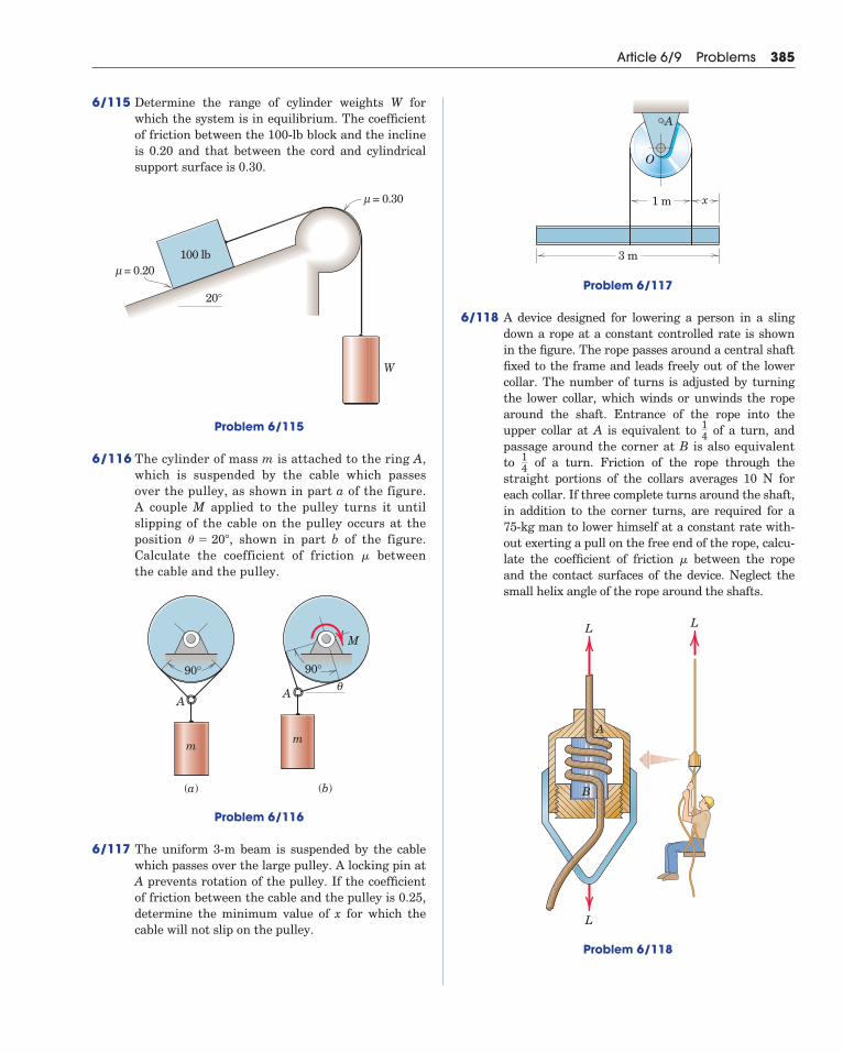
Article 6/9 Problems 385
6/115 Determine the range of cylinder weights W forwhich the system is in equilibrium. The coefficientof friction between the 100-lb block and the inclineis 0.20 and that between the cord and cylindricalsupport surface is 0.30.
Problem 6/115
6/116 The cylinder of mass m is attached to the ring A,which is suspended by the cable which passesover the pulley, as shown in part a of the figure.A couple M applied to the pulley turns it untilslipping of the cable on the pulley occurs at theposition , shown in part b of the figure.Calculate the coefficient of friction betweenthe cable and the pulley.
Problem 6/116
6/117 The uniform 3-m beam is suspended by the cablewhich passes over the large pulley. A locking pin atA prevents rotation of the pulley. If the coefficientof friction between the cable and the pulley is 0.25,determine the minimum value of x for which thecable will not slip on the pulley.
AA
90° 90°
mm
θ
(a) (b)
M
�
� � 20�
= 0.30μ
= 0.20μ
20°
100 lb
W
Problem 6/117
6/118 A device designed for lowering a person in a slingdown a rope at a constant controlled rate is shown in the figure. The rope passes around a central shaftfixed to the frame and leads freely out of the lowercollar. The number of turns is adjusted by turningthe lower collar, which winds or unwinds the ropearound the shaft. Entrance of the rope into theupper collar at A is equivalent to of a turn, andpassage around the corner at B is also equivalentto of a turn. Friction of the rope through thestraight portions of the collars averages 10 N foreach collar. If three complete turns around the shaft,in addition to the corner turns, are required for a 75-kg man to lower himself at a constant rate with-out exerting a pull on the free end of the rope, calcu-late the coefficient of friction between the ropeand the contact surfaces of the device. Neglect thesmall helix angle of the rope around the shafts.
Problem 6/118
L
L
L
A
B
�
14
14
3 m
1 m x
A
O
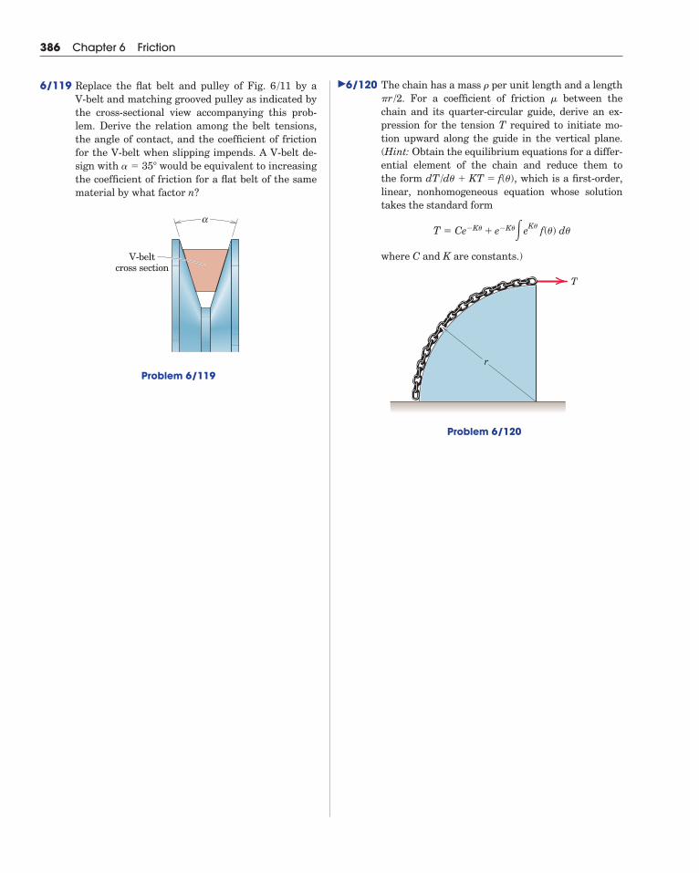
386 Chapter 6 Friction
6/119 Replace the flat belt and pulley of Fig. by a V-belt and matching grooved pulley as indicated bythe cross-sectional view accompanying this prob-lem. Derive the relation among the belt tensions,the angle of contact, and the coefficient of frictionfor the V-belt when slipping impends. A V-belt de-sign with would be equivalent to increasingthe coefficient of friction for a flat belt of the samematerial by what factor n?
Problem 6/119
α
V-beltcross section
� � 35�
6 /11 6/120 The chain has a mass per unit length and a length. For a coefficient of friction between the
chain and its quarter-circular guide, derive an ex-pression for the tension T required to initiate mo-tion upward along the guide in the vertical plane.(Hint: Obtain the equilibrium equations for a differ-ential element of the chain and reduce them to the form , which is a first-order,linear, nonhomogeneous equation whose solutiontakes the standard form
where C and K are constants.)
Problem 6/120
T
r
T � Ce�K� � e�K��eK� f(�) d�
dT/d� � KT � f(�)
��r/2��
6/10 Chapter ReviewIn our study of friction we have concentrated on dry or Coulomb
friction where a simple mechanical model of surface irregularities be-tween the contacting bodies, Fig. 6/1, explains the phenomenon ade-quately for most engineering purposes. This model helps to visualize thethree types of dry-friction problems which are encountered in practice.These problem types are:
1. Static friction of less than the maximum possible value and deter-mined by the equations of equilibrium. (This usually requires acheck to see that F � �sN.)
2. Limiting static friction with impending motion (F � �sN ).
3. Kinetic friction where sliding motion occurs between contactingsurfaces (F � �kN ).
Keep in mind the following when solving dry-friction problems:
1. A coefficient of friction applies to a given pair of mating surfaces. Itis meaningless to speak of a coefficient of friction for a single surface.
2. The coefficient of static friction �s for a given pair of surfaces isusually slightly greater than the kinetic coefficient �k.
3. The friction force which acts on a body is always in the direction tooppose the slipping of the body which takes place or the slippingwhich would take place in the absence of friction.
4. When friction forces are distributed over a surface or along a line,we select a representative element of the surface or line and evalu-ate the force and moment effects of the elemental friction force act-ing on the element. We then integrate these effects over the entiresurface or line.
5. Friction coefficients vary considerably, depending on the exact con-dition of the mating surfaces. Computing coefficients of friction tothree significant figures represents an accuracy which cannot easilybe duplicated by experiment. When cited, such values are includedfor purposes of computational check only. For design computationsin engineering practice, any handbook value for a coefficient of sta-tic or kinetic friction must be viewed as an approximation.
Other forms of friction mentioned in the introductory article of thechapter are important in engineering. Problems which involve fluid fric-tion, for example, are among the most important of the friction prob-lems encountered in engineering, and are studied in the subject of fluidmechanics.
Article 6/10 Chapter Review 387
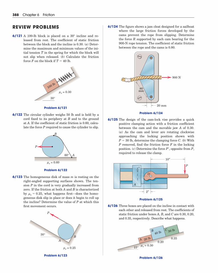
388 Chapter 6 Friction
6/124 The figure shows a jam cleat designed for a sailboatwhere the large friction forces developed by thecams prevent the rope from slipping. Determinethe force R supported by each cam bearing for the900-N rope tension. The coefficient of static frictionbetween the rope and the cams is 0.80.
Problem 6/124
6/125 The design of the cam-lock vise provides a quickpositive clamping action with a friction coefficientbetween the cam and the movable jaw A of 0.30. (a) As the cam and lever are rotating clockwise approaching the locking position shown with
, determine the clamping force C. (b) WithP removed, find the friction force F in the lockingposition. (c) Determine the force P , opposite from P,required to release the clamp.
Problem 6/125
6/126 Three boxes are placed on the incline in contact witheach other and released from rest. The coefficients ofstatic friction under boxes A, B, and C are 0.30, 0.20,and 0.35, respectively. Describe what happens.
Problem 6/126
20 lbA
B C40 lb 30 lb
s = 0.30μ0.20
0.35
15°
10″
2″
P
A
1—2″
O
�
P � 30 lb
900 N
80mm
20 mm
REVIEW PROBLEMS
6/121 A 100-lb block is placed on a incline and re-leased from rest. The coefficient of static frictionbetween the block and the incline is 0.30. (a) Deter-mine the maximum and minimum values of the ini-tial tension T in the spring for which the block willnot slip when released. (b) Calculate the frictionforce F on the block if .
Problem 6/121
6/122 The circular cylinder weighs 50 lb and is held by acord fixed to its periphery at B and to the ground at A. If the coefficient of static friction is 0.60, calcu-late the force P required to cause the cylinder to slip.
Problem 6/122
6/123 The homogeneous disk of mass m is resting on theright-angled supporting surfaces shown. The ten-sion P in the cord is very gradually increased fromzero. If the friction at both A and B is characterizedby , what happens first––does the homo-geneous disk slip in place or does it begin to roll upthe incline? Determine the value of P at which thisfirst movement occurs.
Problem 6/123
s = 0.25μ
30°
P
AB
�s � 0.25
B
P
60° A
s = 0.60μ
100 lb
s = 0.30μ
30°
T � 40 lb
30�
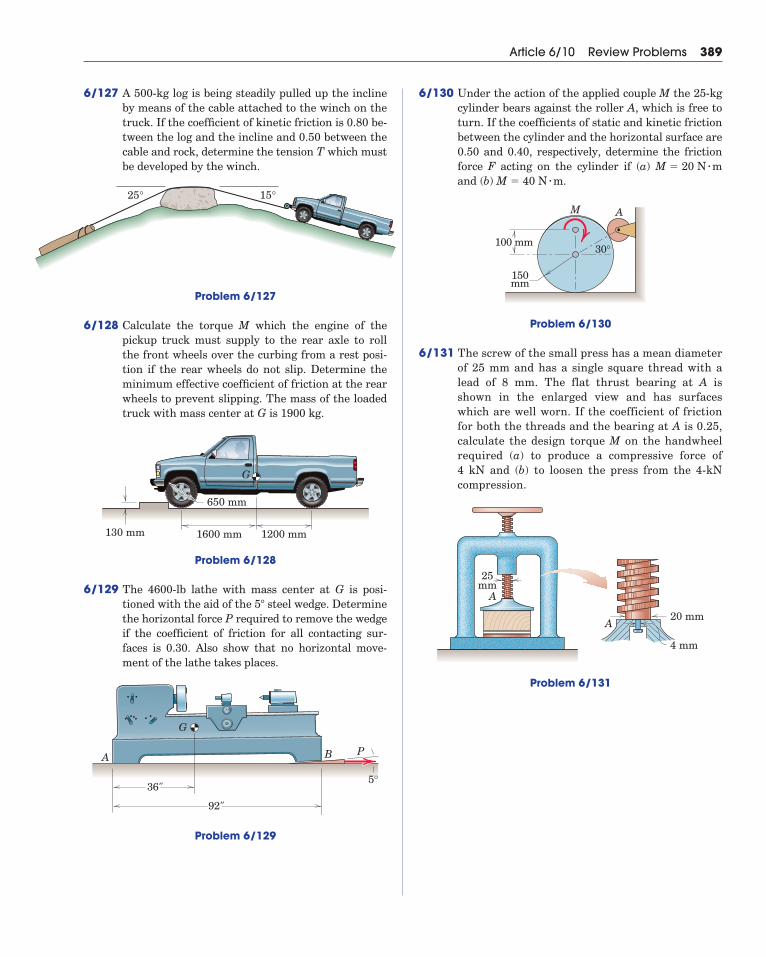
Article 6/10 Review Problems 389
6/127 A 500-kg log is being steadily pulled up the inclineby means of the cable attached to the winch on thetruck. If the coefficient of kinetic friction is 0.80 be-tween the log and the incline and 0.50 between thecable and rock, determine the tension T which mustbe developed by the winch.
6/130 Under the action of the applied couple M the 25-kgcylinder bears against the roller A, which is free toturn. If the coefficients of static and kinetic frictionbetween the cylinder and the horizontal surface are0.50 and 0.40, respectively, determine the frictionforce F acting on the cylinder if (a)and (b) .
Problem 6/130
6/131 The screw of the small press has a mean diameterof 25 mm and has a single square thread with alead of 8 mm. The flat thrust bearing at A isshown in the enlarged view and has surfaceswhich are well worn. If the coefficient of frictionfor both the threads and the bearing at A is 0.25,calculate the design torque M on the handwheelrequired (a) to produce a compressive force of 4 kN and (b) to loosen the press from the 4-kNcompression.
Problem 6/131
A
25mm
4 mm
20 mmA
M A
30°100 mm
150mm
M � 40 N � mM � 20 N � m
25° 15°
Problem 6/127
6/128 Calculate the torque M which the engine of thepickup truck must supply to the rear axle to rollthe front wheels over the curbing from a rest posi-tion if the rear wheels do not slip. Determine theminimum effective coefficient of friction at the rearwheels to prevent slipping. The mass of the loadedtruck with mass center at G is 1900 kg.
Problem 6/128
6/129 The 4600-lb lathe with mass center at G is posi-tioned with the aid of the steel wedge. Determinethe horizontal force P required to remove the wedgeif the coefficient of friction for all contacting sur-faces is 0.30. Also show that no horizontal move-ment of the lathe takes places.
Problem 6/129
G
B PA
36"
92"
5°
5�
1600 mm 1200 mm
G
130 mm
650 mm
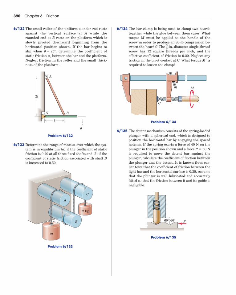
390 Chapter 6 Friction
6/134 The bar clamp is being used to clamp two boards together while the glue between them cures. Whattorque M must be applied to the handle of thescrew in order to produce an 80-lb compression be-tween the boards? The -in.-diameter single-threadscrew has 12 square threads per inch, and the effective coefficient of friction is 0.20. Neglect anyfriction in the pivot contact at C. What torque M isrequired to loosen the clamp?
Problem 6/134
6/135 The detent mechanism consists of the spring-loadedplunger with a spherical end, which is designed toposition the horizontal bar by engaging the spacednotches. If the spring exerts a force of 40 N on theplunger in the position shown and a force is required to move the detent bar against theplunger, calculate the coefficient of friction betweenthe plunger and the detent. It is known from ear-lier tests that the coefficient of friction between thelight bar and the horizontal surface is 0.30. Assumethat the plunger is well lubricated and accuratelyfitted so that the friction between it and its guide isnegligible.
Problem 6/135
60° 60° P
P � 60 N
C
M
�
38
6/132 The small roller of the uniform slender rod restsagainst the vertical surface at A while therounded end at B rests on the platform which isslowly pivoted downward beginning from thehorizontal position shown. If the bar begins toslip when , determine the coefficient ofstatic friction between the bar and the platform.Neglect friction in the roller and the small thick-ness of the platform.
Problem 6/132
6/133 Determine the range of mass m over which the sys-tem is in equilibrium (a) if the coefficient of staticfriction is 0.20 at all three fixed shafts and (b) if thecoefficient of static friction associated with shaft Bis increased to 0.50.
Problem 6/133
C
A
B
2 kg
m
O
A
B
l
2l
θ
�s
� � 25�
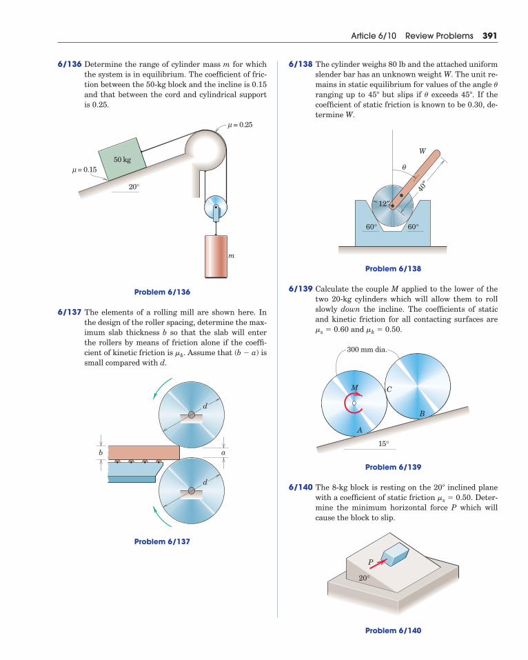
Article 6/10 Review Problems 391
6/136 Determine the range of cylinder mass m for whichthe system is in equilibrium. The coefficient of fric-tion between the 50-kg block and the incline is 0.15and that between the cord and cylindrical supportis 0.25.
Problem 6/136
6/137 The elements of a rolling mill are shown here. Inthe design of the roller spacing, determine the max-imum slab thickness b so that the slab will enterthe rollers by means of friction alone if the coeffi-cient of kinetic friction is . Assume that issmall compared with d.
Problem 6/137
a
d
d
b
(b � a)�k
= 0.25μ
= 0.15μ
20°
50 kg
m
6/138 The cylinder weighs 80 lb and the attached uniformslender bar has an unknown weight W. The unit re-mains in static equilibrium for values of the angle ranging up to but slips if exceeds . If thecoefficient of static friction is known to be 0.30, de-termine W.
Problem 6/138
6/139 Calculate the couple M applied to the lower of thetwo 20-kg cylinders which will allow them to rollslowly down the incline. The coefficients of staticand kinetic friction for all contacting surfaces are
and .
Problem 6/139
6/140 The 8-kg block is resting on the inclined planewith a coefficient of static friction . Deter-mine the minimum horizontal force P which willcause the block to slip.
Problem 6/140
P
20°
�s � 0.5020�
300 mm dia.
15°
C
B
A
M
�k � 0.50�s � 0.60
40″
12″
60° 60°
W
θ
45��45�
�
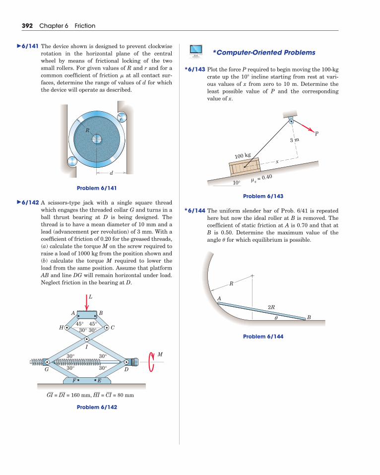
392 Chapter 6 Friction
*Computer-Oriented Problems
6/143 Plot the force P required to begin moving the 100-kgcrate up the incline starting from rest at vari-ous values of x from zero to 10 m. Determine theleast possible value of P and the correspondingvalue of x.
Problem 6/143
6/144 The uniform slender bar of Prob. 6/41 is repeatedhere but now the ideal roller at B is removed. Thecoefficient of static friction at A is 0.70 and that atB is 0.50. Determine the maximum value of theangle for which equilibrium is possible.
Problem 6/144
A
R
B
2R
�
P
100 kg
3 m
x
s = 0.40μ10°
10�
6/141 The device shown is designed to prevent clockwiserotation in the horizontal plane of the centralwheel by means of frictional locking of the twosmall rollers. For given values of R and r and for acommon coefficient of friction at all contact sur-faces, determine the range of values of d for whichthe device will operate as described.
Problem 6/141
6/142 A scissors-type jack with a single square threadwhich engages the threaded collar G and turns in aball thrust bearing at D is being designed. Thethread is to have a mean diameter of 10 mm and alead (advancement per revolution) of 3 mm. With acoefficient of friction of 0.20 for the greased threads,(a) calculate the torque M on the screw required toraise a load of 1000 kg from the position shown and(b) calculate the torque M required to lower theload from the same position. Assume that platformAB and line DG will remain horizontal under load.Neglect friction in the bearing at D.
Problem 6/142
A B
L
H C
I
G D
M
45° 45°30°
30°
30°
30°
30°
GI = DI = 160 mm, HI = CI = 80 mm
30°
F E
d
r
R
�
�
�
*
*
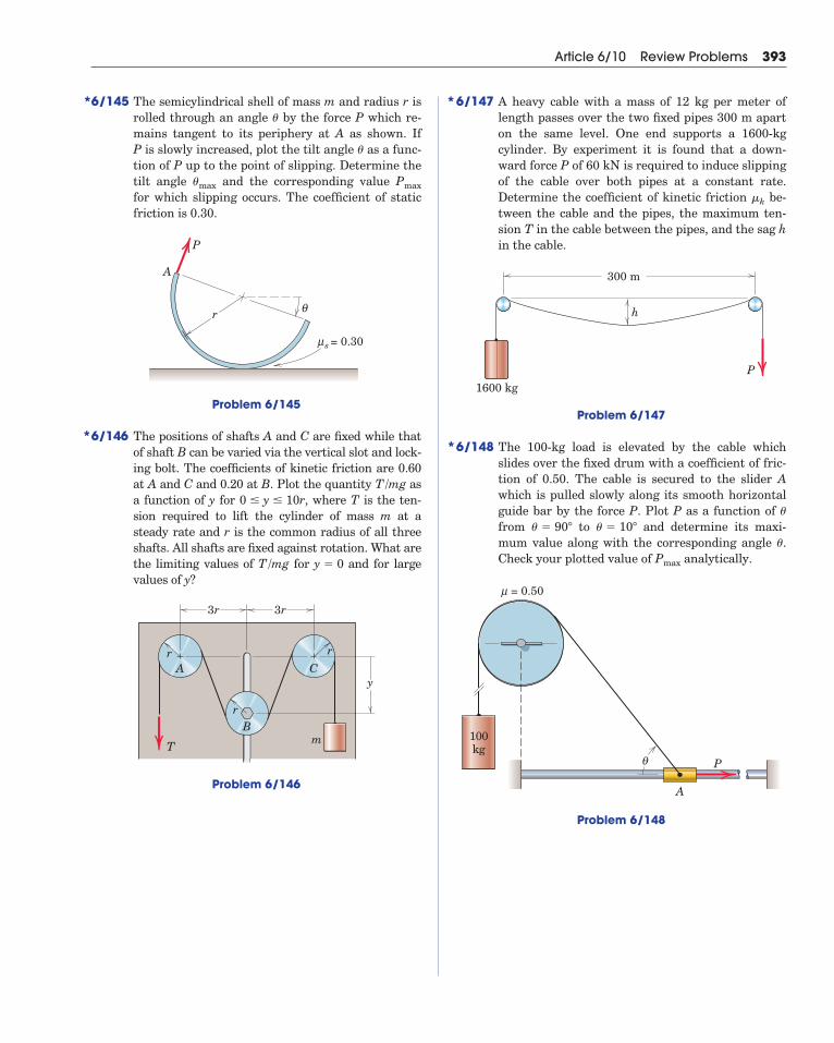
Article 6/10 Review Problems 393
6/145 The semicylindrical shell of mass m and radius r isrolled through an angle by the force P which re-mains tangent to its periphery at A as shown. If P is slowly increased, plot the tilt angle as a func-tion of P up to the point of slipping. Determine thetilt angle and the corresponding value for which slipping occurs. The coefficient of staticfriction is 0.30.
Problem 6/145
6/146 The positions of shafts A and C are fixed while thatof shaft B can be varied via the vertical slot and lock-ing bolt. The coefficients of kinetic friction are 0.60at A and C and 0.20 at B. Plot the quantity asa function of y for , where T is the ten-sion required to lift the cylinder of mass m at asteady rate and r is the common radius of all threeshafts. All shafts are fixed against rotation. What arethe limiting values of for and for largevalues of y?
Problem 6/146
r
3r
y
3r
r
r
A
B
C
mT
y � 0T/mg
0 � y � 10rT/mg
P
A
r
= 0.30
θ
sμ
Pmax�max
�
�
6/147 A heavy cable with a mass of 12 kg per meter oflength passes over the two fixed pipes 300 m aparton the same level. One end supports a 1600-kgcylinder. By experiment it is found that a down-ward force P of 60 kN is required to induce slippingof the cable over both pipes at a constant rate. Determine the coefficient of kinetic friction be-tween the cable and the pipes, the maximum ten-sion T in the cable between the pipes, and the sag hin the cable.
Problem 6/147
6/148 The 100-kg load is elevated by the cable whichslides over the fixed drum with a coefficient of fric-tion of 0.50. The cable is secured to the slider Awhich is pulled slowly along its smooth horizontalguide bar by the force P. Plot P as a function of from to and determine its maxi-mum value along with the corresponding angle .Check your plotted value of analytically.
Problem 6/148
100kg
P
A
θ
= 0.50μ
Pmax
�
� � 10�� � 90�
�
300 m
1600 kg
h
P
�k
*
*
*
*
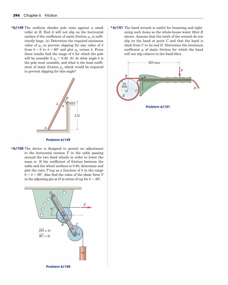
394 Chapter 6 Friction
6/151 The band wrench is useful for loosening and tight-ening such items as the whole-house water filter Eshown. Assume that the teeth of the wrench do notslip on the band at point C and that the band isslack from C to its end D. Determine the minimumcoefficient of static friction for which the bandwill not slip relative to the fixed filter.
Problem 6/151
D
P
AB
OE
C
250 mm
55mm
�
6/149 The uniform slender pole rests against a smallroller at B. End A will not slip on the horizontalsurface if the coefficient of static friction is suffi-ciently large. (a) Determine the required minimumvalue of to prevent slipping for any value of from to and plot versus . Fromthese results find the range of for which the polewill be unstable if . (b) At what angle isthe pole most unstable, and what is the least coeffi-cient of static friction which would be requiredto prevent slipping for this angle?
Problem 6/149
6/150 The device is designed to permit an adjustment to the horizontal tension T in the cable passingaround the two fixed wheels in order to lower themass m. If the coefficient of friction between thecable and the wheel surfaces is 0.40, determine andplot the ratio as a function of in the range
. Also find the value of the shear force Vin the adjusting pin at D in terms of mg for .
Problem 6/150
D
m
r
A
CB
r
O
T
BC = 2r___DO = 3r___
� � 60�
0 � � � 90�
�T/mg
A
L
B
L/2
θ
�s
��s � 0.40�
��s� � 60�� � 0��s
�s
*
**

503
Absolute system of units, 10Acceleration, of a body, 8, 121
due to gravity, 11Accuracy, 13Action and reaction, principle of, 8, 25, 110, 173, 204, 225, 279Active force, 402Active-force diagram, 403Addition of vectors, 6, 25, 28, 482Aerostatics, 306Angle, of friction, 339
of repose, 342Approximations, 14, 254Archimedes, 3Area, first moment of, 238
second moment of, 238, 441Area moments of inertia, see Moments of inertia of areasAtmospheric pressure, 307Axes, choice of, 27, 68, 114, 179, 237, 240
rotation of, 465Axis, moment, 38, 74
Beams, concentrated loads on, 273definition of, 272distributed loads on, 273external effects, 273internal effects, 279loading-shear relation for, 280, 281resultant of forces on cross section of, 279shear-moment relation for, 280, 281, 284statically determinate and indeterminate, 272types of, 272
Bearing friction, 368Belt friction, 377Bending moment, 279Bending-moment diagram, 280Bodies, interconnected, 204, 402Body, deformable, 5
rigid, 4Body force, 24, 234Boundary conditions, 293British system of units, 9Buoyancy, center of, 312
force of, 312principle of, 311
Cables, catenary, 295flexible, 291length of, 294, 297parabolic, 293tension in, 294, 297
Cajori, F., 7Center, of buoyancy, 312
of gravity, 25, 235of mass, 235, 237of pressure, 308
Centroids, 238of composite figures, 254by integration, 238
of irregular volumes, 255table of, 497by theorems of Pappus, 264
Coefficient, of friction, 338, 339, 495of rolling resistance, 378
Collinear forces, equilibrium of, 121Components, of a force, 26, 27, 28
rectangular, 6, 26, 27, 28, 66scalar, 27of a vector, 6, 26, 27, 28, 66
Composite areas, moment of inertia of, 456Composite bodies, center of mass of, 254Composite figures, centroid of, 254Compression in truss members, 175, 178Computer-oriented problems, 17, 104, 168, 229, 331, 392,
438, 475Concentrated forces, 24, 233
on beams, 273Concurrent forces, equilibrium of, 121, 146
resultant of, 25, 28, 59, 89Cone of friction, 340Constant of gravitation, 12, 496Constraint, 124, 148
adequacy of, 125, 149partial, 149proper and improper, 125redundant, 126, 149
Coordinates, choice of, 27, 67, 114, 240, 325, 443Coplanar forces, equilibrium of, 121, 122
resultant of, 28, 58Coulomb, 336Couple, 50, 76
equivalent, 50moment of, 50, 76resolution of, 51, 89resultant, 58, 88, 89vector representation of, 50, 76work of, 399
Cross or vector product, 39, 74, 483
D’Alembert, J., 3da Vinci, 3Deformable body, 4Degrees of freedom, 404, 422, 433Density, 237, 495Derivative of vector, 484Derivatives, table of, 485Diagram, active-force, 403, 419
bending-moment, 280free-body, 16, 110, 114, 146shear-force, 280
Differential element, choice of, 239Differentials, order of, 13, 239, 325Dimensions, homogeneity of, 17Direction cosines, 7, 66Disk friction, 369Displacement, 398
virtual, 400
Index

specifications of, 24unit of, 9work of, 398
Force–couple system, 51, 58, 77Force system, concurrent, 59, 76, 89, 121, 146
coplanar, 58general, 23, 89parallel, 26, 59, 89
Formulation of problems, 14Frames, defined, 204, 225
equilibrium of, 204Frames and machines, rigidity of, 204Free-body diagram, 16, 110, 114, 146Freedom, degrees of, 404, 422, 433Free vector, 5, 6, 50, 76Friction, angle of, 339
bearing, 368, 369belt, 377circle of, 368coefficients of, 338, 339, 495cone of, 340disk, 369dry or Coulomb, 336, 337fluid, 336internal, 336journal bearing, 368kinetic, 338limiting, 338in machines, 357mechanism of, 337pivot, 369problems in dry friction, 341, 387rolling, 378screw thread, 358static, 338types of, 336wedge, 357work of, 404
Gage pressure, 307Galileo, 3Gas, 306Graphical representation, 15, 25, 26, 58Gravitation, constant of, 12, 496
law of, 12Gravitational force, 12, 25, 113, 234Gravitational potential energy, 418Gravitational system of units, 10Gravity, acceleration due to, 11
center of, 25, 235Guldin, Paul, 264Gyration, radius of, 443
Homogeneity, dimensional, 17Hydrostatic pressure, 307, 309, 310Hydrostatics, 306Hyperbolic functions, 296
Ideal systems, 402Impending motion, 338, 340, 341Inclined axes, area moments of inertia about, 465Inertia, 4, 442
area moments of, see Moments of inertia of areasprincipal axes of, 466products of, 464
Inertia force, 442Integrals, table of selected, 486Integration, choice of element for, 240, 325
numerical techniques for, 491, 493of vectors, 485
504 Index
Distributed forces, 24, 233, 234, 325, 326on beams, 273
Distributive laws, 40, 483Dot or scalar product, 67, 398, 483Dynamics, 4, 8
Efficiency, mechanical, 405Elastic potential energy, 417Energy, criterion for equilibrium, 422
criterion for stability, 422elastic, 417potential, 417, 419, 421
Equilibrium, alternative equations of, 123categories of, 121, 146of collinear forces, 121of concurrent forces, 121, 146condition of, 58, 121, 145, 401, 403of coplanar forces, 121, 122energy criterion for, 421, 422equations of, 121, 145of interconnected rigid bodies, 204, 402of machines, 204necessary and sufficient conditions for, 121, 145neutral, 421of parallel forces, 121, 148of a particle, 401of a rigid body, 401stability of, 125, 421with two degrees of freedom, 404by virtual work, 400, 401, 403
Euler, 3External effects of force, 24
First moment of area, 238Fixed vector, 5, 24Flexible cables, 291
differential equation for, 292Fluids, 306
friction in, 336incompressible, 307pressure in, 306
Foot, 9Force, action of, 23, 111, 112, 146, 147
active, 402body, 24, 234buoyancy, 312components of, 26, 27, 66concentrated, 24, 233concept of, 4contact, 24coplanar system of, 58distributed, 24, 233, 234, 325, 326effects of, 23external, 24friction, 113, 335gravitational, 12, 25, 113, 234inertia, 442intensity of, 234internal, 24, 234, 279, 403kinds of, 24magnetic, 24, 113measurement of, 25mechanical action of, 111, 112, 147moment of, 38, 74polygon, 58, 123reactive, 24, 402remote action of, 113resolution of, 26, 27, 66, 67resultant, 58, 88, 89, 235, 325shear, 279, 306

Interconnected bodies, 204, 402Internal effects of force, 24, 234, 279, 403Internal friction, 336International System of units, 9
Joints, method of, 176, 198, 224Joule, 400Journal bearings, friction in, 368
Kilogram, 9, 10, 12Kilopound, 10Kinetic friction, 338
coefficient of, 339, 495
Lagrange, 3Laplace, 3Law, associative, 482
commutative, 482, 483of cosines, 482distributive, 40, 483of gravitation, 12parallelogram, 6, 25, 58of sines, 482Pascal’s, 306triangle, 6, 25
Laws of motion, Newton’s, 7Length, standard unit of, 10Limit, mathematical, 14Line of action, 24Liquids, 307Loading-shear relation for beams, 280, 281
Mach, Ernst, 40Machines, defined, 204, 225
equilibrium of, 204friction in, 357ideal or real, 336
Mass, 4, 10center of, 235, 237unit of, 9, 10
Mathematical limit, 13Mathematical model, 15Mathematics, selected topics in, 479Mechanical efficiency, 405Mechanical system, 110Mechanics, 3Metacenter, 313Metacentric height, 313Meter, 10Method, of joints, 176, 198, 224
of problem solution, 16, 99, 114, 163, 224, 325, 387, 433of sections, 188, 198, 224of virtual work, 397
Metric units, 9Minimum energy, principle of, 405Mohr’s circle, 469Moment, bending, 279
components of, 75of a couple, 50, 76of a force, 38, 74torsional, 279, 442units of, 38vector representation of, 39, 74
Moment arm, 38Moment axis, 38, 74Moments, principle of, 59, 88, 235, 241, 325Moments of inertia of areas, 441
for composite areas, 456dimensions and units of, 443about inclined axes, 465by integration, 442
Index 505
maximum and minimum, 466, 467Mohr’s circle representation of, 467polar, 443principal axes of, 466radius of gyration for, 443rectangular, 442table of, 497tabular computation of, 456transfer of axes for, 444, 464
Morin, 336Motion, impending, 338, 340, 341Multi-force members, 204
Neutral equilibrium, 421Newton, Isaac, 3Newton’s laws, 7Newton (unit), 9Newton’s method, 489Numerical integration, 491, 493
Order of differentials, 13, 239, 325
Pappus, 264theorems of, 264
Parallel-axis theorems, for area moments of inertia, 445Parallel forces, equilibrium of, 121, 148
resultant of, 26, 59, 89Parallelogram law, 6, 25, 58Particle, 4Particles, equilibrium of, 401Pascal (unit), 234Pascal’s law, 306Pivot friction, 369Polar moment of inertia, 443Polygon, of forces, 58, 123Potential energy, 417, 419, 421
datum for, 418units of, 418, 419
Pound, standard, 10Pound force, 9Pound mass, 10Pressure, 234, 306
atmospheric, 307center of, 308fluid, 306gage, 307hydrostatic, 307, 309, 310on submerged surfaces, 307, 309, 310
Principal axes of inertia, 466Principia, 7Principle, of action and reaction, 8, 25, 110, 173, 204,
225, 279of buoyancy, 311of concurrency of forces, 122of minimum energy, 421of moments, 59, 88, 235, 241, 325of transmissibility, 5, 24, 58of virtual work, 401, 403, 420
Products of inertia, 464about inclined axes, 465
Products of vectors, 39, 67, 74, 75, 398, 483
Radius of gyration, 443Reactive forces, 24, 402Rectangular components, 6, 26, 27, 28, 66Rectangular moments of inertia, 442Redundancy, external and internal, 178, 197Redundant supports, 125, 149Repose, angle of, 342Resolution, force, 26, 27, 66, 67
force and couple, 51, 58, 77

of derivatives, 485of mathematical relations, 479of solar system constants, 496
Tension in truss members, 175, 176Theorem, of Pappus, 264
of Varignon, 39, 59, 75Three-force member, 122Thrust bearing, friction in, 369Time, 4, 10Ton, 10Torque, see Moment, of forceTorsional moment, 279, 442Transfer of axes, for moments of inertia, 444
for products of inertia, 464Transmissibility, principle of, 5, 24, 58Triangle law, 6, 25Triple scalar product, 75, 484Triple vector product, 484Trusses, definition, 175
plane, 175simple, 175, 197space, 197, 224stability of, 178, 197statical determinacy of, 178, 197, 224types of, 174
Two-force members, 122, 175
U.S. customary units, 9Units, 8, 38, 400Unit vectors, 7, 27, 66, 68, 75Unstable equilibrium, 421
Varignon, 3Varignon’s theorem, 39, 59, 75Vector equation, 8Vectors, 4, 23
addition of, 6, 25, 28, 482components of, 6, 26, 27, 28, 66couple, 50, 76cross or vector product of, 39, 74, 483derivative of, 484dot or scalar product of, 67, 398, 483fixed, 5, 24free, 5, 6, 50, 76moment, 39, 74notation for, 5resolution of, 26, 27, 66, 67sliding, 5, 24, 38, 76subtraction of, 6, 482unit, 7, 27, 66, 68, 75
Vector sum, of couples, 76, 88of forces, 25, 28, 58, 88
Virtual displacement, 400Virtual work, 397, 400
for elastic systems, 420for ideal systems, 402, 403for a particle, 401for a rigid body, 401
Viscosity, 336
Wear in bearings, 369Wedges, friction in, 357Weight, 12, 25, 113, 234Work, of a couple, 399
of a force, 398units of, 400virtual, 397, 400
Wrench, 89
506 Index
Resultant, of concurrent forces, 25, 28, 59, 89of coplanar forces, 28, 58couple, 58, 88, 89of fluid pressure, 307, 309, 311force, 58, 88, 89, 235, 325of forces on beam cross section, 279of general force system, 89of parallel forces, 26, 59, 89
Right-hand rule, 38, 67, 74, 483Rigid bodies, interconnected, 204, 402Rigid body, 4
equilibrium of, 401Rolling resistance, coefficient of, 378
Scalar, 4Scalar components, 27Scalar or dot product, 67, 398, 483Screw, friction in, 358Second moment of area, 238, 441Sections, method of, 188, 198, 224Series, selected expansions, 485Shear force, 279, 306Shear-force diagram, 280Shear-moment relation for beams, 280, 281, 282Shear stress, 442Singularity functions, 282SI units, 9Sliding vector, 5, 24, 38, 76Slug, 9Space, 4Space trusses, 197, 224Specific weight, 234Spring, linear and nonlinear, 112, 113
potential energy of, 417stiffness of, 417
Stability, of equilibrium, 125, 421of floating bodies, 312for single degree-of-freedom system, 421of trusses, 178, 197
Statically determinate structures, 125, 148, 173, 178, 197Statically indeterminate structures, 125, 149, 178, 197, 204Static friction, 338
coefficient of, 338, 495Statics, 4Stevinus, 3Stiffness of spring, 417Stress, 234
shear, 442Structures, statical determinacy of, 125, 148, 173, 178, 197, 204
types of, 173Submerged surfaces, pressure on, 307, 309, 310Subtraction of vectors, 6, 482Symmetry, considerations of, 237, 464System, with elastic members, 417
force–couple, 51, 58, 77of forces, concurrent, 25, 59, 75, 89, 121, 146
coplanar, 58general, 23, 88parallel, 59, 89, 121, 148
ideal, 402of interconnected bodies, 204, 402mechanical, 110real, 404of units, 8
Table, of area moments of inertia, 497of centroids, 497of coefficients of friction, 495of densities, 495
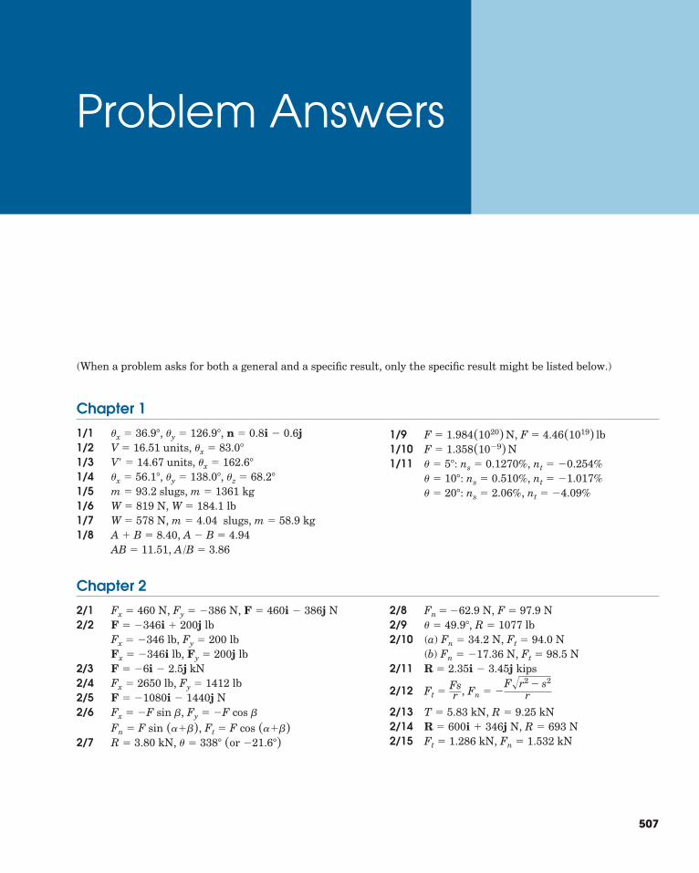
507
Problem Answers
Chapter 1
1/1 , , 1/2 units,1/3 units,1/4 , , 1/5 slugs, kg1/6 ,1/7 , slugs, kg1/8 ,
,
1/9 ,1/101/11 ,
,, nt � �4.09%ns � 2.06%� � 20�:
nt � �1.017%ns � 0.510%� � 10�:nt � �0.254%ns � 0.1270%� � 5�:
F � 1.358(10�9) NF � 4.46(1019) lbF � 1.984(1020) N
A/B � 3.86AB � 11.51A � B � 4.94A � B � 8.40
m � 58.9m � 4.04 W � 578 NW � 184.1 lbW � 819 N
m � 1361m � 93.2�z � 68.2��y � 138.0��x � 56.1�
�x � 162.6�V� � 14.67�x � 83.0�V � 16.51
n � 0.8i � 0.6j�y � 126.9��x � 36.9�
Chapter 2
2/1 , , 2/2
2/3 kN2/4 lb, lb2/5 N2/6 ,
,2/7
2/8 N2/9 lb2/10 (a) N, N
(b) N, N2/11 kips
2/12 ,
2/13 kN, kN2/14 N, N2/15 kN, kNFn � 1.532Ft � 1.286
R � 693R � 600i � 346jR � 9.25T � 5.83
Fn � �F�r2 � s2
rFt �Fsr
R � 2.35i � 3.45jFt � 98.5Fn � �17.36
Ft � 94.0Fn � 34.2� � 49.9�, R � 1077Fn � �62.9 N, F � 97.9
R � 3.80 kN, � � 338� (or �21.6�)Ft � F cos (���)Fn � F sin (���)
Fy � �F cos �Fx � �F sin �F � �1080i � 1440j
Fy � 1412Fx � 2650i � 2.5jF � �6
Fx � �346i lb, Fy � 200j lbFx � �346 lb, Fy � 200 lbF � �346i � 200j lb
F � 460i � 386j NFy � �386 NFx � 460 N
(When a problem asks for both a general and a specific result, only the specific result might be listed below.)
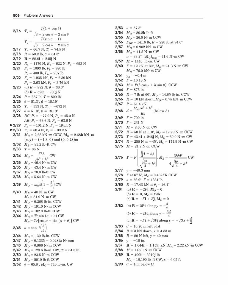
508 Problem Answers
2/16
2/17 N, N2/18 lb,2/19 N2/20 N, N, N2/21 lb, lb
lb, lb2/22 kN, kN
kN, kN2/23 (a) N,
(b) N2/24 lb, lb2/25 ,2/26 ,2/27 ,2/28 N, N
N, N2/29 N, N2/30 N, N2/31 CCW,
and2/32 CW2/33 N
2/34 CW
2/35 CW2/36 CW2/37 lb-ft CW2/38 CW
2/39 CW
2/40 CWCW
2/41 lb-in. CCW2/42 CCW2/43 lb-ft CCW2/44 CW
CW
2/45
2/46 lb-in. CCW2/472/48 CCW2/49 lb-in. CW, lb2/50 CCW2/51 lb-ft CCW2/52 lb-in. CW
2/532/54 lb-ft2/55 CCW2/56 ,2/57 CW2/58 CW
, CW2/59 lb-in. CW2/60 CW
CW2/61 m2/62 N2/63 CCW2/64 lb2/65 , lb-in. CCW2/66 , CCW2/67 kN
2/68 (below A)
2/69 lb2/70 N2/71 CW2/72 , CCW2/73 N, CW2/74 , CW2/75 CCW
2/76 , CW
2/772/78 , CCW2/79 , lb2/802/81 (a) ,
(b) , (c) ,
2/82 (a) along
(b)
(c)
2/83 left of A2/842/852/862/87 kN m CCW2/88 CCW2/89
ft2/90 below Od � 4 m
MA � 18,190 lb-ft CW, x � 6.05R � 400i � 3010j lbM � 148.0 N � m
�R � 1.644i � 1.159j kN, MA � 2.22y � �10 in.R � 80 N left, y � 40 mmR � 3 kN down, x � 4.33 md � 10.70 m
R � �Fi ��3Fj along y � ��3 x �
d2
R � �2Fi along y �
3d4
y � �d2
R � 2Fi
MO � 0R � �Fi � FjMO � FdkR � 0
MO � 0R � �2FjR � 17.43 kN at �x � 26.1�
F � 1361� � 56.9�
MO � 0.462FRF at 67.5�
y � �40.3 mm
MB �3hbF
4�b2
4� h2
F � F �b2
i � hj
�b2
4� h2�
M � 21.7 N � mMC � 174.9 N � mR � 250 N at �45�
MO � 60.0 N � mF � 43.4i � 246jMO � 17.29 N � mR � 50 N at 110�
M � 2.60 N � mF � 231F � 700
d �MA�b2 � h2
Rb
P � 51.4MO � 0.75 kN � mR � 10 kN down
MO � 14.85R � 7 lb at 60�
F � 875M � F(b cos � � h sin �)F � 16.18yA � �0.4MB � 76.0 kN � m
kN � mMO � 24F � 12 kN at 30�,M � 1440
(MO)max � 41.6 N � m� � 33.2�
MO � 41.5 N � mMO � 0.902 kN � m
R � 220 lb at 94.6�FDE � 141.6 lbMO � 26.8 N � mMO � 80.2k� � 57.5�
� � 65.8�, MO � 740MO � 5010MO � 23.5 N � m
T � 64.3MO � 128.6MO � 0.866 N � mMO � 0.1335 � 0.0282s N � mmMO � 130
� � tan�1�hb�
MP � Tr[cos � � sin (� � �)]MO � Tr sin (� � �)MO � 102.8MO � 191.0 N � mMO � 0.268MA� 81.9 N � mMB � 48 N � m
MO � mgb�1 �2��
MO � 5.64 N � mMO � 70.0
N � mMO � 43.4MO � 46.4 N � m
MO �Fbh
�b2 � h2
T � 36MB � 83.2 lb-ft
(0, 0.78)m(x, y) � (�1.3, 0)MO � 2.68k kN � mMO � 2.68 kN � m
Ft � �39.2Fn � 50.4Fy � 194.4Fx � �101.2Pn � 63.6AB: Pt � 63.6
Pn � 45.0BC: Pt � �77.9� � 18.19�� � 51.3�
Tt � �672 NTn � 333 N� � 18.19�� � 51.3�
T � 800P � 537R � 520i � 700j
� � 36.6�R � 872Pb � 3.76Pa � 3.63Fb � 2.39Fa � 1.935
Pb � 207Pa � 400Fb � 980Fa � 1093
Pa � 693Rb � 622Ra � 1170R � 88.8i � 245j
� � 84.3�R � 50.2Tt � 74.5Tn � 66.7
Ty �T(sin � � 1)
�3 � 2 cos � � 2 sin �
Tx �T(1 � cos �)
�3 � 2 cos � � 2 sin �
�
�
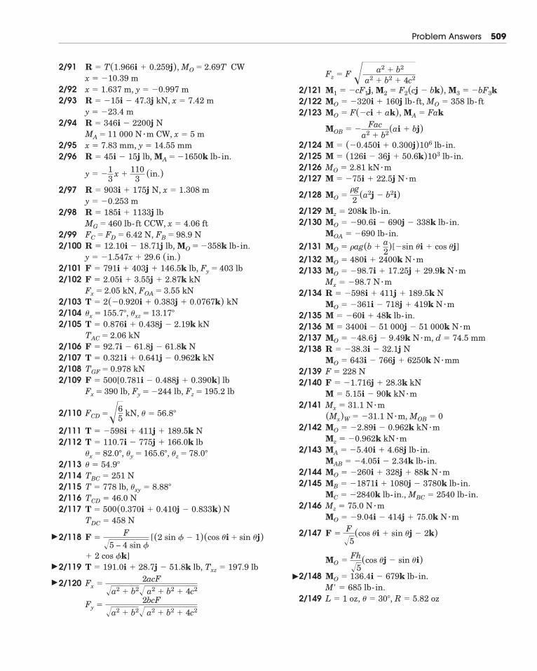
Problem Answers 509
2/91 CW
2/922/93
2/94
2/952/96
2/97
2/98
2/992/100
2/1012/102
2/1032/1042/105
2/1062/1072/1082/109
2/110
2/1112/112
2/1132/1142/1152/1162/117
2/118
2/119
2/120
Fy �2bcF
�a2 � b2� a2 � b2 � 4c2
Fx �2acF
�a2 � b2� a2 � b2 � 4c2
T � 191.0i � 28.7j � 51.8k lb, Txz � 197.9 lb� 2 cos �k]
(cos �i � sin �j)F �F
�5 – 4 sin � [(2 sin � � 1)
TDC � 458 NT � 500(0.370i � 0.410j � 0.833k) NTCD � 46.0 NT � 778 lb, �xy � 8.88�
TBC � 251 N� � 54.9�
�x � 82.0�, �y � 165.6�, �z � 78.0�
T � 110.7i � 775j � 166.0k lbT � �598i � 411j � 189.5k N
FCD ��65
kN, � � 56.8�
Fx � 390 lb, Fy � �244 lb, Fz � 195.2 lbF � 500[0.781i � 0.488j � 0.390k] lbTGF � 0.978 kNT � 0.321i � 0.641j � 0.962k kNF � 92.7i � 61.8j � 61.8k NTAC � 2.06 kNT � 0.876i � 0.438j � 2.19k kN�x � 155.7�, �xz � 13.17�
T � 2(�0.920i � 0.383j � 0.0767k) kNFx � 2.05 kN, FOA � 3.55 kNF � 2.05i � 3.55j � 2.87k kN
Fy � 403 lbF � 791i � 403j � 146.5k lb,y � �1.547x � 29.6 (in.)
MO � �358k lb-in.R � 12.10i � 18.71j lb,FC � FD � 6.42 N, FB � 98.9 NMG � 460 lb-ft CCW, x � 4.06 ftR � 185i � 1133j lby � �0.253 mR � 903i � 175j N, x � 1.308 m
y � �13
x �110
3 (in.)
R � 45i � 15j lb, MA � �1650k lb-in.x � 7.83 mm, y � 14.55 mmMA � 11 000 N � m CW, x � 5 mR � 346i � 2200j Ny � �23.4 mR � �15i � 47.3j kN, x � 7.42 mx � 1.637 m, y � �0.997 mx � �10.39 mR � T(1.966i � 0.259j), MO � 2.69T
�
�
��
2/1212/1222/123
2/1242/1252/1262/127
2/128
2/1292/130
2/1312/1322/133
2/134
2/1352/1362/1372/138
2/1392/140
2/141
2/142
2/143
2/1442/145
,2/146
2/147
2/148
2/149 L � 1 oz, � � 30�, R � 5.82 ozM� � 685 lb-in.MO � 136.4i � 679k lb-in.
MO �Fh�5
(cos �j � sin �i)
F �F�5
(cos �i � sin �j � 2k)
MO � �9.04i � 414j � 75.0k N � mMz � 75.0 N � m
MBC � 2540 lb-in.MC � �2840k lb-in.MB � �1871i � 1080j � 3780k lb-in.MO � �260i � 328j � 88k N � mMAB � �4.05i � 2.34k lb-in.MA � �5.40i � 4.68j lb-in.Mz � �0.962k kN � mMO � �2.89i � 0.962k kN � m(Mx)W � �31.1 N � m, MOB � 0Mx � 31.1 N � mM � 5.15i � 90k kN � mF � �1.716j � 28.3k kNF � 228 NMO � 643i � 766j � 6250k N � mmR � �38.3i � 32.1j NMO � �48.6 j � 9.49k N � m, d � 74.5 mmM � 3400i � 51 000j � 51 000k N � mM � �60i � 48k lb-in.MO � �361i � 718j � 419k N � mR � �598i � 411j � 189.5k NMx � �98.7 N � mMO � �98.7i � 17.25j � 29.9k N � mMO � 480i � 2400k N � m
MO � �ag(b �a2)[�sin �i � cos �j]
MOA � �690 lb-in.MO � �90.6i � 690j � 338k lb-in.Mz � 208k lb-in.
MO ��g2 (a2j � b2i)
M � �75i � 22.5j N � mMO � 2.81 kN � mM � (126i � 36j � 50.6k)103 lb-in.M � (�0.450i � 0.300j)106 lb-in.
MOB � �Fac
a2 � b2(ai � bj)
MO � F(�ci � ak), MA � FakMO � �320i � 160j lb-ft, MO � 358 lb-ft
M2 � F2(cj � bk), M3 � �bF3kM1 � �cF1j,
Fz � F � a2 � b2
a2 � b2 � 4c2
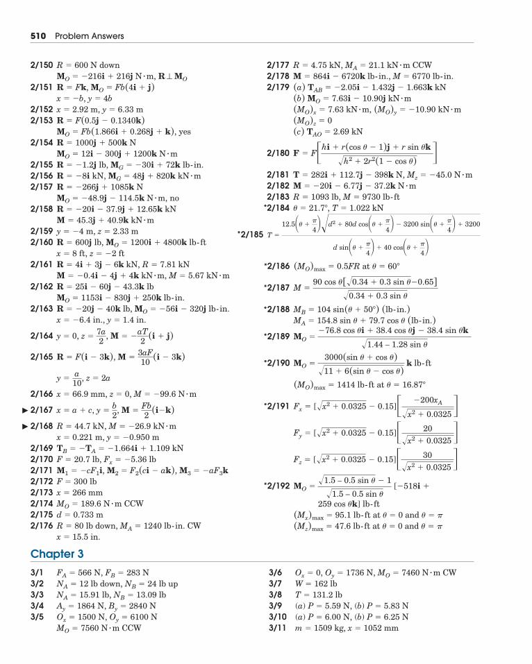
510 Problem Answers
2/185 T �
12.5�� ��
4��d2 � 80d cos�� ��
4� � 3200 sin�� ��
4� � 3200
d sin�� ��
4� � 40 cos�� ��
4�
2/150
2/151
2/1522/153
2/154
2/155 ,2/1562/157
, no2/158
2/1592/160
2/161
2/162
2/163
2/164
2/165
2/166 ,
2/167
2/168
2/1692/1702/1712/1722/1732/1742/1752/176
x � 15.5 in.R � 80 lb down, MA � 1240 lb-in. CWd � 0.733 mMO � 189.6 N � m CCWx � 266 mmF � 300 lbM1 � �cF1i, M2 � F2(ci � ak), M3 � �aF3kF � 20.7 lb, Fx � �5.36 lbTB � �TA � �1.664i � 1.109 kNx � 0.221 m, y � �0.950 mR � 44.7 kN, M � �26.9 kN � m
x � a � c, y �b2
, M �Fb2 (i�k)
M � �99.6 N � mx � 66.9 mm, z � 0
y �a10
, z � 2a
M �3aF10 (i � 3k)R � F(i � 3k),
y � 0, z �7a2
, M � �aT2 (i � j)
x � �6.4 in., y � 1.4 in.R � �20j � 40k lb, MO � �56i � 320j lb-in.MO � 1153i � 830j � 250k lb-in.R � 25i � 60j � 43.3k lbM � �0.4i � 4j � 4k kN � m, M � 5.67 kN � mR � 4i � 3j � 6k kN, R � 7.81 kNx � 8 ft, z � �2 ftR � 600j lb, MO � 1200i � 4800k lb-fty � �4 m, z � 2.33 mM � 45.3j � 40.9k kN � mR � �20i � 37.9j � 12.65k kNMO � �48.9j � 114.5k N � mR � �266j � 1085k NR � �8i kN, MG � 48j � 820k kN � m
MG � �30i � 72k lb-in.R � �1.2j lbMO � 12i � 300j � 1200k N � mR � 1000j � 500k N
yesMO � Fb(1.866i � 0.268j � k),R � F(0.5j � 0.1340k)x � 2.92 m, y � 6.33 mx � �b, y � 4bR � Fk, MO � Fb(4i � j)MO � �216i � 216j N � m, R ⊥ MO
R � 600 N down 2/1772/1782/179
,
2/180
2/181 ,2/1822/1832/184 � � 21.7�, T � 1.022 kN
R � 1093 lb, M � 9730 lb-ftM � �20i � 6.77j � 37.2k N � m
Mz � �45.0 N � mT � 282i � 112.7j � 398k N
F � F�hi � r(cos � � 1)j � r sin �k
�h2 � 2r2(1 � cos �) �(c) TAO � 2.69 kN(MO)z � 0
(MO)y � �10.90 kN � m(MO)x � 7.63 kN � m(b) MO � 7.63i � 10.90j kN � m(a) TAB � �2.05i � 1.432j � 1.663k kNM � 864i � 6720k lb-in., M � 6770 lb-in.R � 4.75 kN, MA � 21.1 kN � m CCW
2/186
2/187
2/188
2/189
2/190
2/191
2/192
(Mz)max � 47.6 lb-ft at � � 0 and � � �
(Mx)max � 95.1 lb-ft at � � 0 and � � �
259 cos �k] lb-ft
[�518i �MO ��1.5 – 0.5 sin � � 1
�1.5 – 0.5 sin �
Fz � [�x2 � 0.0325 � 0.15]� 30�x2 � 0.0325 �
Fy � [�x2 � 0.0325 � 0.15]� 20�x2 � 0.0325 �
Fx � [�x2 � 0.0325 � 0.15]� �200xA
�x2 � 0.0325 �(MO)max � 1414 lb-ft at � � 16.87�
MO �3000(sin � � cos �)
�11 � 6(sin � � cos �)k lb-ft
MO ��76.8 cos �i � 38.4 cos �j � 38.4 sin �k
�1.44 – 1.28 sin �
MA � 154.8 sin � � 79.7 cos � (lb-in.)MB � 104 sin(� � 50�) (lb-in.)
M �90 cos �[�0.34 � 0.3 sin ��0.65]
�0.34 � 0.3 sin �
(MO)max � 0.5FR at � � 60�
Chapter 3
3/13/23/33/43/5
3/63/73/83/9 (a)3/10 (a)3/11 m � 1509 kg, x � 1052 mm
P � 6.00 N, (b) P � 6.25 NP � 5.59 N, (b) P � 5.83 N
T � 131.2 lbW � 162 lbOx � 0, Oy � 1736 N, MO � 7460 N � m CW
MO � 7560 N � m CCWOx � 1500 N, Oy � 6100 NAy � 1864 N, By � 2840 NNA � 15.91 lb, NB � 13.09 lbNA � 12 lb down, NB � 24 lb upFA � 566 N, FB � 283 N
*
*
*
*
*
*
*
*
*
�
�
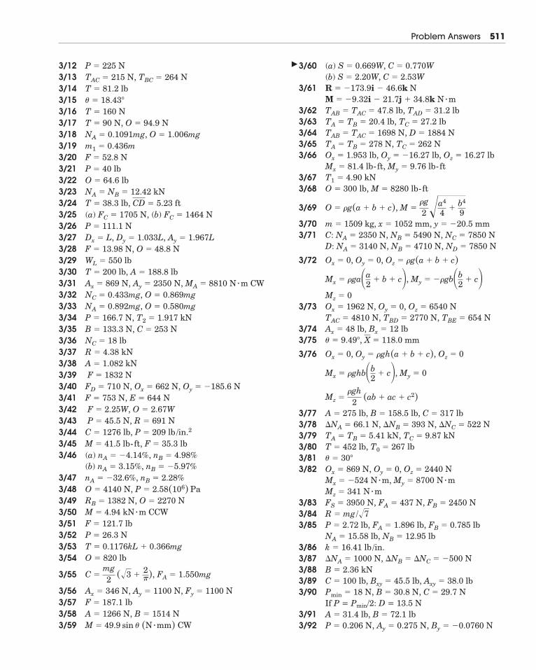
Problem Answers 511
3/123/133/143/153/163/173/183/193/203/213/223/233/243/25 (a)3/263/273/283/293/303/31 CW3/323/333/343/353/363/373/383/393/403/413/423/433/443/453/46 (a)
(b)3/473/483/493/503/513/523/533/54
3/55
3/563/573/583/59
3/60 (a)(b)
3/61
3/623/633/643/653/66
3/673/68
3/69
3/703/71
3/72
3/73
3/743/75
3/76
3/773/783/793/803/813/82
3/833/843/85
3/863/873/883/893/90
If P = Pmin/2: D = 13.5 N3/913/92 P � 0.206 N, Ay � 0.275 N, By � �0.0760 N
A � 31.4 lb, B � 72.1 lb
Pmin � 18 N, B � 30.8 N, C � 29.7 NC � 100 lb, Bxy � 45.5 lb, Axy � 38.0 lbB � 2.36 kN�NA � 1000 N, �NB � �NC � �500 Nk � 16.41 lb /in.NA � 15.58 lb, NB � 12.95 lbP � 2.72 lb, FA � 1.896 lb, FB � 0.785 lbR � mg/�7FS � 3950 N, FA � 437 N, FB � 2450 NMz � 341 N � m
My � 8700 N � mMx � �524 N � m,Ox � 869 N, Oy � 0, Oz � 2440 N� � 30�
T � 452 lb, T0 � 267 lbTA � TB � 5.41 kN, TC � 9.87 kN�NA � 66.1 N, �NB � 393 N, �NC � 522 NA � 275 lb, B � 158.5 lb, C � 317 lb
Mz ��gh
2 (ab � ac � c2)
Mx � �ghb�b2
� c�, My � 0
Ox � 0, Oy � �gh(a � b � c), Oz � 0
� � 9.49�, X � 118.0 mmAx � 48 lb, Bx � 12 lb
TBD � 2770 N, TBE � 654 NTAC � 4810 N,Ox � 1962 N, Oy � 0, Oz � 6540 NMz � 0
Mx � �ga�a2
� b � c�, My � ��gb�b2
� c�Ox � 0, Oy � 0, Oz � �g(a � b � c)D: NA � 3140 N, NB � 4710 N, ND � 7850 NC: NA � 2350 N, NB � 5490 N, NC � 7850 Nm � 1509 kg, x � 1052 mm, y � �20.5 mm
O � �g(a � b � c), M ��g2 �a4
4�
b4
9
O � 300 lb, M � 8280 lb-ftT1 � 4.90 kNMx � 81.4 lb-ft, My � 9.76 lb-ftOx � 1.953 lb, Oy � �16.27 lb, Oz � 16.27 lbTA � TB � 278 N, TC � 262 NTAB � TAC � 1698 N, D � 1884 NTA � TB � 20.4 lb, TC � 27.2 lbTAB � TAC � 47.8 lb, TAD � 31.2 lbM � �9.32i � 21.7j � 34.8k N � mR � �173.9i � 46.6k N
S � 2.20W, C � 2.53WS � 0.669W, C � 0.770W
M � 49.9 sin � (N � mm) CWA � 1266 N, B � 1514 NF � 187.1 lbAx � 346 N, Ay � 1100 N, Fy � 1100 N
C �mg2
(�3 �2�), FA � 1.550mg
O � 820 lbT � 0.1176kL � 0.366mgP � 26.3 NF � 121.7 lbM � 4.94 kN � m CCWRB � 1382 N, O � 2270 NO � 4140 N, P � 2.58(106) PanA � �32.6%, nB � 2.28%
nA � 3.15%, nB � �5.97%nA � �4.14%, nB � 4.98%
M � 41.5 lb-ft, F � 35.3 lbC � 1276 lb, P � 209 lb /in.2P � 45.5 N, R � 691 NF � 2.25W, O � 2.67W
F � 753 N, E � 644 NFD � 710 N, Ox � 662 N, Oy � �185.6 NF � 1832 N
A � 1.082 kNR � 4.38 kNNC � 18 lbB � 133.3 N, C � 253 NP � 166.7 N, T2 � 1.917 kNNA � 0.892mg, O � 0.580mgNC � 0.433mg, O � 0.869mgAx � 869 N, Ay � 2350 N, MA � 8810 N � mT � 200 lb, A � 188.8 lbWL � 550 lbF � 13.98 N, O � 48.8 NDx � L, Dy � 1.033L, Ay � 1.967LP � 111.1 N
FC � 1705 N, (b) FC � 1464 NT � 38.3 lb, CD � 5.23 ftNA � NB � 12.42 kNO � 64.6 lbP � 40 lbF � 52.8 Nm1 � 0.436mNA � 0.1091mg, O � 1.006mgT � 90 N, O � 94.9 NT � 160 N� � 18.43�
T � 81.2 lbTAC � 215 N, TBC � 264 NP � 225 N �
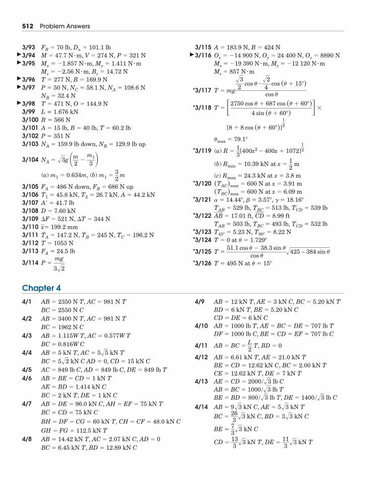
512 Problem Answers
3/933/943/95
3/963/97
3/983/99 L = 1.676 kN3/1003/1013/1023/103
3/104
(a) (b)
3/1053/1063/1073/1083/109 ,3/1103/1113/1123/113
3/114
3/1153/116
3/117
3/118
3/119 (a)
(b)
(c)3/120
3/121
3/122
3/1233/124
3/125
3/126 T � 495 N at � � 15�
T �51.1 cos � � 38.3 sin �
cos ��425 – 384 sin �
T � 0 at � � 1.729�
T45� � 5.23 N, T90� � 8.22 NTAB � 503 lb, TBC � 493 lb, TCD � 532 lbAB � 17.01 ft, CD � 8.99 ftTAB � 529 lb, TBC � 513 lb, TCD � 539 lb� � 14.44�, � � 3.57�, � � 18.16�
(TBC)max � 600 N at x � 6.09 m(TAC)max � 600 N at x � 3.91 m
Rmax � 24.3 kN at x � 3.8 m
Rmin � 10.39 kN at x �12
m
R �13
[400x2 � 400x � 1072]12
�max � 79.1�
[8 � 8 cos (� � 60�)]12
�T � �2750 cos � � 687 cos (� � 60�)4 sin (� � 60�) �
T � mg
�32
cos ���24
cos (� � 15�) cos �
Mz � 857 N � mMx � �19 390 N � m, My � �12 120 N � mOx � �14 900 N, Oy � 24 400 N, Oz � 8890 NA � 183.9 N, B � 424 N
P �mg
3�2
FA � 24.5 lbT � 1053 NTA � 147.2 N, TB � 245 N, TC � 196.2 Nx� 199.2 mm
�T � 344 N�F � 521 ND � 7.60 kNA� � 41.7 lbT1 � 45.8 kN, T2 � 26.7 kN, A � 44.2 kNFA � 486 N down, FB � 686 N up
m1 �32
mm1 � 0.634m,
NA � �3g �m2
�m1
3 �NA � 159.9 lb down, NB � 129.9 lb upP � 351 NA � 15 lb, B � 40 lb, T � 60.2 lbR � 566 N
T � 471 N, O � 144.9 NNB � 32.4 NP � 50 N, NC � 58.1 N, NA � 108.6 NT � 277 N, B � 169.9 N Mz � �2.56 N � m, Bz � 14.72 NMx � �1.857 N � m, My � 1.411 N � mM � 47.7 N � m, V � 274 N, P � 321 NFB � 70 lb, Dn � 101.1 lb
Chapter 4
*
*
*
*
*
*
**
*
*
�
�
�
�
�
�
BH � DF � CG � 60 kN T, CH � CF � 48.0 kN C
4/1
4/2
4/3
4/4
4/54/6
4/7BC � CD � 75 kN CAB � DE � 96.0 kN C, AH � EF � 75 kN TBC � 2 kN T, DE � 1 kN CAE � BD � 1.414 kN CAB � BE � CD � 1 kN TAC � 849 lb C, AD � 849 lb C, DE � 849 lb T
CD � 15 kN CBC � 5�2 kN C AD � 0,AB � 5 kN T, AC � 5�5 kN TBC � 0.816W CAB � 1.115W T, AC � 0.577W TBC � 1962 N CAB � 3400 N T, AC � 981 N TBC � 2550 N CAB � 2350 N T, AC � 981 N T 4/9
4/10
4/11
4/12
4/13
,
4/14
, DE �113
�3 kN TCD �133
�3 kN T
BE �73�3 kN C
BC �263
�3 kN C, BD � 3�3 kN C
AB � 9�3 kN C, AE � 5�3 kN T
DE � 1400 /�3 lb CBE � BD � 800 /�3 lb TAB � BC � 1000 /�3 lb TAE � CD � 2000 /�3 lb CCE � 12.62 kN T, DE � 7 kN TBE � CD � 12.62 kN C, BC � 2.00 kN TAB � 6.61 kN T, AE � 21.0 kN T
AB � BC �L2
T, BD � 0
DF � 1000 lb C, BE � CD � EF � 707 lb CAB � 1000 lb T, AE � BC � DE � 707 lb TCD � DE � 6 kN CBD � 6 kN T, BE � 5.20 kN CAB � 12 kN T, AE � 3 kN C, BC � 5.20 kN T
4/8BC � 6.45 kN T, BD � 12.89 kN CAB � 14.42 kN T, AC � 2.07 kN C, AD � 0GH � FG � 112.5 kN T
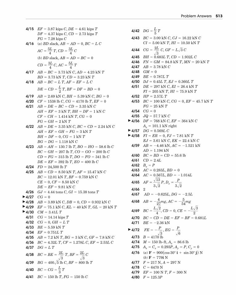
Problem Answers 513
4/15
4/16 (a)
(b)
4/17
4/18
4/194/204/21
4/22
4/23
4/244/25
4/264/274/284/294/304/314/324/334/344/354/364/37
4/38
4/39
4/40
4/41
4/42
4/43
4/44
4/454/464/474/484/494/504/51
4/524/53
4/544/554/56
4/574/58
4/59
4/604/614/624/634/64
4/65
4/66 24/67
4/68
4/69
4/704/71
4/72
4/734/744/754/76 (a)
(b)4/774/784/794/80 F � 125.3P
EF � 100 N T, F � 300 NC � 6470 NF � 217 N, A � 297 N
F � 779i NF � 900(cos 30� i � sin 30� j) N
Ax � Cx � 0.293P, Ay � P, Cy � 0M � 150 lb-ft, Ax � 86.6 lbB � 4170 lb
FE � �P�3
, EG �P�6
BE � �2.36 kNBC � CD � DE � EF � BF � 0.681L
BC �L�2
4, CD � 0, CE � �
L�32
AB � �4
27mg, AC � �
554
mg
AD � �0.625L, DG � �2.5L
AF ��13
3�2P, Dx �
P3�2
AC � 0.567L, BD � �1.014LAC � 0.283L, BD � 0Bx � PCD � 2.4LBC � BD � CD � 55.6 lbAD � 1.194 kNAB � �4.46 kN, AC � �1.521 kNEJ � 3.61 kN C, EK � 22.4 kN CFI � ER � 0, FJ � 7.81 kN TDG � 0.569L CAx � 101.1 kN rightDF � 768 kN C, EF � 364 kN CJQ � 57.7 kN CCG � 0FG � 25 kN TBC � 100 kN C, CG � 0, EF � 45.7 kN THP � 2.57L TFI � 205 kN T, HI � 75.9 kN TDE � 297 kN C, EI � 26.4 kN TDJ � 0.45L T, EJ � 0.360L TBE � 0.787L TGM � 0AB � 3.78 kN CFN � GM � 84.8 kN T, MN � 20 kN TBH � 0.683L T, CD � 1.932L C
CG �2L�3
C, GF � L�3 C
CI � 5.00 kN T, HI � 10.50 kN TBC � 3.00 kN C, CJ � 16.22 kN C
DG �L5
T
BC � 150 lb T, FG � 150 lb C
BC � CG �L3
T
BG � 400�5 lb C, BF � 800 lb T
BC � BE �2L�3
T, BF �2L�3
C
DG � L TBC � 4.32L T, CF � 1.278L C, EF � 2.53L CAB � 7.2 kN T, BG � 3 kN C, GF � 7.8 kN CEF � 0.751L TBE � 5.59 kN TCG � 0, GH � L TCG � 14.14 kips TCM � 3.41L TEF � 75.1 kN C, KL � 40 kN T, GL � 20 kN TAB � 3.89 kN C, DB � 0, CD � 0.932 kN CCG � 0GJ � 4.44 tons C, GI � 15.38 tons TDE � EF � 9.81 kN CCE � 0, CF � 8.50 kN CBC � 12.01 kN T, BF � 0.759 kN CAB � CD � 8.50 kN T, AF � 15.47 kN CFD � 24,500 lb TDE � EF � 392 lb T, EO � 400 lb CCD � FG � 315 lb T, DO � FO � 341 lb CBC � GH � 207 lb T, CO � GO � 200 lb CAB � AH � 130.7 lb T, BO � HO � 58.6 lb CBG � DG � 1.118 kN C
CG � 1 kN TBH � DF � 0,AH � EF � GH � FG � 3 kN TAB � DE � 3.35 kN C, BC � CD � 2.24 kN CFG � GH � 2 kN T
CG � 0CF � CH � 1.414 kN T,AH � EF � 3 kN T, BH � DF � 1 kN CAB � DE � BC � CD � 3.35 kN CCF � 1538 lb C, CG � 4170 lb T, EF � 0AB � 2.69 kN C, BH � 5.39 kN C, BG � 0
DE � CD �L2
T, BF � DF � BD � 0
AB � BC � L T, AF � EF � L CBD � 3.73 kN T, CD � 3.23 kN TAB � BC � 3.73 kN C, AD � 4.23 kN T
CD �3L4
C, AC �5L4
T
BD slack, AB � AD � BC � 0
AC �5L4
T, CD �3L4
C
BD slack, AB � AD � 0, BC � L CFG � 7.28 kips CDF � 4.37 kips C, CD � 2.73 kips TEF � 3.87 kips C, DE � 4.61 kips T
�
�
�
�
�
�
�
�
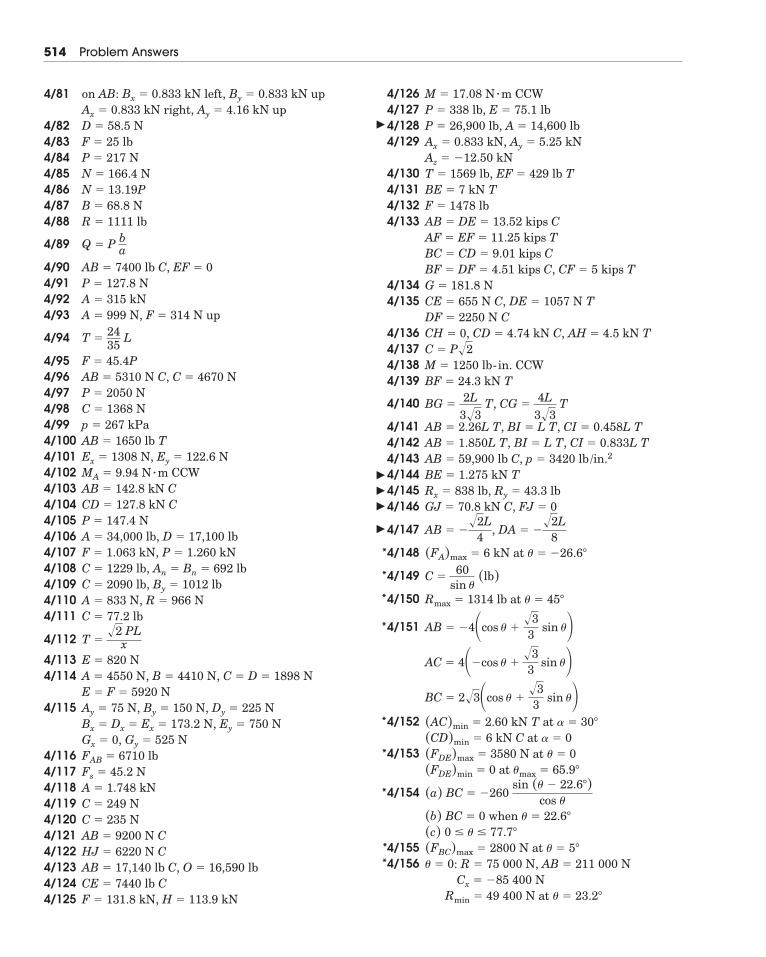
514 Problem Answers
4/81 on
4/824/834/844/854/864/874/88
4/89
4/904/914/924/93
4/94
4/954/964/974/984/994/1004/1014/1024/1034/1044/1054/1064/1074/1084/1094/1104/111
4/112
4/1134/114
4/115
4/1164/1174/1184/1194/1204/1214/1224/1234/1244/125
4/1264/1274/1284/129
4/1304/1314/1324/133
4/1344/135
4/1364/1374/1384/139
4/140
4/1414/1424/1434/1444/1454/146
4/147
4/148
4/149
4/150
4/151
4/152
4/153
4/154
4/1554/156
Rmin � 49 400 N at � � 23.2�
Cx � �85 400 N� � 0: R � 75 000 N, AB � 211 000 N(FBC)max � 2800 N at � � 5�
(c) 0 � � � 77.7�
(b) BC � 0 when � � 22.6�
(a) BC � �260sin (� � 22.6�)
cos �
(FDE)min � 0 at �max � 65.9�
(FDE)max � 3580 N at � � 0(CD)min � 6 kN C at � � 0(AC)min � 2.60 kN T at � � 30�
BC � 2�3�cos � ��33
sin ��AC � 4��cos � �
�33
sin ��AB � �4�cos � �
�33
sin ��Rmax � 1314 lb at � � 45�
C �60
sin �(lb)
(FA)max � 6 kN at � � �26.6�
AB � ��2L
4, DA � �
�2L8
GJ � 70.8 kN C, FJ � 0Rx � 838 lb, Ry � 43.3 lbBE � 1.275 kN TAB � 59,900 lb C, p � 3420 lb /in.2AB � 1.850L T, BI � L T, CI � 0.833L TAB � 2.26L T, BI � L T, CI � 0.458L T
BG �2L
3�3T, CG �
4L3�3
T
BF � 24.3 kN TM � 1250 lb-in. CCWC � P�2CH � 0, CD � 4.74 kN C, AH � 4.5 kN TDF � 2250 N CCE � 655 N C, DE � 1057 N TG � 181.8 N
CF � 5 kips TBF � DF � 4.51 kips C,BC � CD � 9.01 kips CAF � EF � 11.25 kips TAB � DE � 13.52 kips CF � 1478 lbBE � 7 kN TT � 1569 lb, EF � 429 lb TAz � �12.50 kNAx � 0.833 kN, Ay � 5.25 kNP � 26,900 lb, A � 14,600 lbP � 338 lb, E � 75.1 lbM � 17.08 N � m CCW
F � 131.8 kN, H � 113.9 kNCE � 7440 lb CAB � 17,140 lb C, O � 16,590 lbHJ � 6220 N CAB � 9200 N CC � 235 NC � 249 NA � 1.748 kNFs � 45.2 NFAB � 6710 lbGx � 0, Gy � 525 NBx � Dx � Ex � 173.2 N, Ey � 750 NAy � 75 N, By � 150 N, Dy � 225 NE � F � 5920 NA � 4550 N, B � 4410 N, C � D � 1898 NE � 820 N
T ��2 PL
x
C � 77.2 lbA � 833 N, R � 966 NC � 2090 lb, By � 1012 lbC � 1229 lb, An � Bn � 692 lbF � 1.063 kN, P � 1.260 kNA � 34,000 lb, D � 17,100 lbP � 147.4 NCD � 127.8 kN CAB � 142.8 kN CMA � 9.94 N � m CCWEx � 1308 N, Ey � 122.6 NAB � 1650 lb Tp � 267 kPaC � 1368 NP � 2050 NAB � 5310 N C, C � 4670 NF � 45.4P
T �2435
L
A � 999 N, F � 314 N upA � 315 kNP � 127.8 NAB � 7400 lb C, EF � 0
Q � P ba
R � 1111 lbB � 68.8 NN � 13.19PN � 166.4 NP � 217 NF � 25 lbD � 58.5 NAx � 0.833 kN right, Ay � 4.16 kN up
AB: Bx � 0.833 kN left, By � 0.833 kN up
�
�
�
�
�
*
*
*
*
*
*
*
**
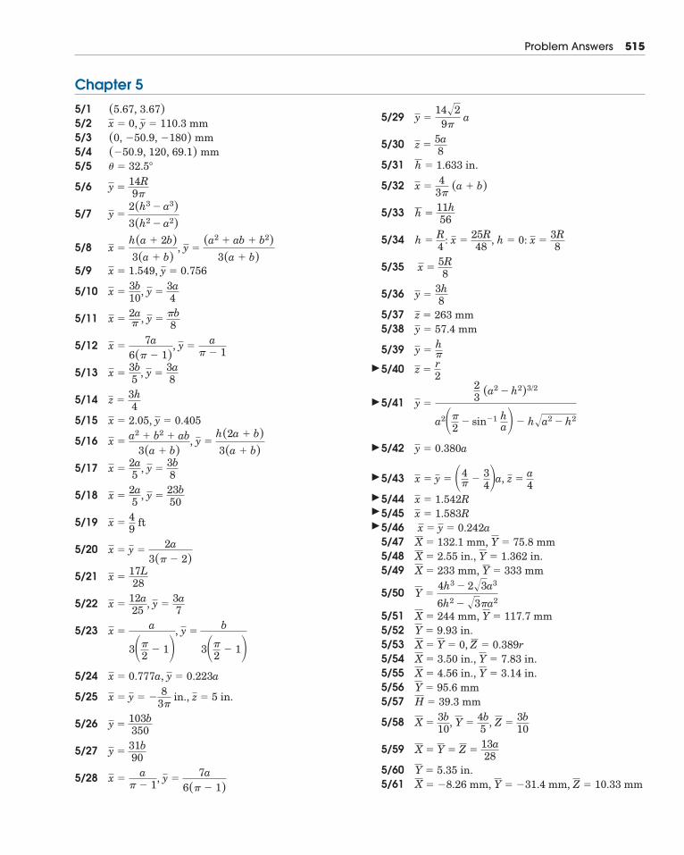
Problem Answers 515
Chapter 5
5/15/25/35/45/5
5/6
5/7
5/8
5/9
5/10
5/11
5/12
5/13
5/14
5/15
5/16
5/17
5/18
5/19
5/20
5/21
5/22
5/23
5/24
5/25
5/26
5/27
5/28
5/29
5/30
5/31
5/32
5/33
5/34
5/35
5/36
5/375/38
5/39
5/40
5/41
5/42
5/43
5/445/455/465/475/485/49
5/50
5/515/525/535/545/555/565/57
5/58
5/59
5/605/61 X � �8.26 mm, Y � �31.4 mm, Z � 10.33 mm
Y � 5.35 in.
X � Y � Z �13a28
X �3b10
, Y �4b5
, Z �3b10
H � 39.3 mmY � 95.6 mmX � 4.56 in., Y � 3.14 in.X � 3.50 in., Y � 7.83 in.X � Y � 0, Z � 0.389rY � 9.93 in.X � 244 mm, Y � 117.7 mm
Y �4h3 � 2�3a3
6h2 � �3�a2
X � 233 mm, Y � 333 mmX � 2.55 in., Y � 1.362 in.X � 132.1 mm, Y � 75.8 mmx � y � 0.242a
x � 1.583Rx � 1.542R
x � y � �4� �
34�a, z �
a4
y � 0.380a
y �
23 (a2 � h2)3/2
a2��2
� sin�1 ha� � h�a2 � h2
z �r2
y �h�
y � 57.4 mmz � 263 mm
y �3h8
x �5R8
h �R4
: x �25R48
, h � 0: x �3R8
h �11h56
x �4
3�(a � b)
h � 1.633 in.
z �5a8
y �14�2
9�a
x �a
� � 1, y �
7a6(� � 1)
y �31b90
y �103b350
x � y � �8
3� in., z � 5 in.
x � 0.777a, y � 0.223a
x �a
3��2
� 1�, y �
b
3��2
� 1�
x �12a25
, y �3a7
x �17L28
x � y �2a
3(� � 2)
x �49
ft
x �2a5
, y �23b50
x �2a5
, y �3b8
x �a2 � b2 � ab
3(a � b), y �
h(2a � b)3(a � b)
x � 2.05, y � 0.405
z �3h4
x �3b5
, y �3a8
x �7a
6(� � 1), y �
a� � 1
x �2a� , y �
�b8
x �3b10
, y �3a4
x � 1.549, y � 0.756
x �h(a � 2b)3(a � b)
, y �(a2 � ab � b2)
3(a � b)
y �2(h3 � a3)3(h2 � a2)
y �14R9�
� � 32.5�
(�50.9, 120, 69.1) mm(0, �50.9, �180) mmx � 0, y � 110.3 mm(5.67, 3.67)
�
�
�
�
�
�
�
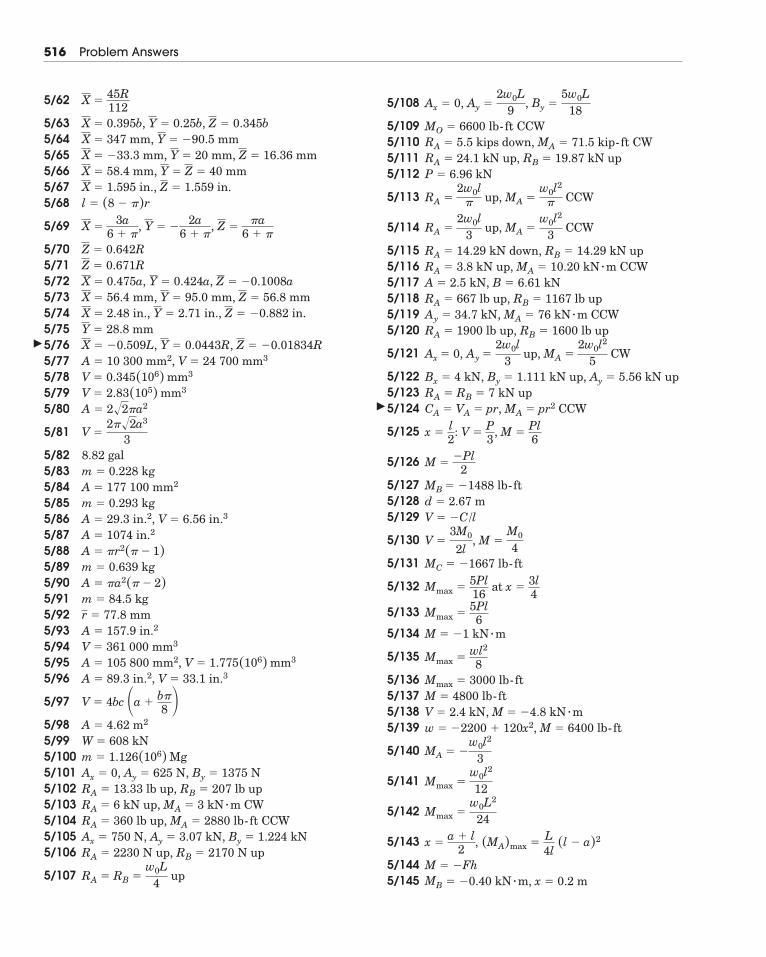
516 Problem Answers
5/62
5/635/645/655/665/675/68
5/69
5/705/715/725/735/745/755/765/775/785/795/80
5/81
5/825/835/845/855/865/875/885/895/905/915/925/935/945/955/96 ,
5/97
5/985/995/1005/1015/1025/1035/1045/1055/106
5/107
5/108
5/1095/1105/1115/112
5/113
5/114
5/1155/1165/1175/1185/1195/120
5/121
5/1225/1235/124
5/125
5/126
5/1275/1285/129
5/130
5/131
5/132
5/133
5/134
5/135
5/1365/1375/1385/139
5/140
5/141
5/142
5/143
5/1445/145 MB � �0.40 kN � m, x � 0.2 m
M � �Fh
x �a � l
2, (MA)max �
L4l
(l � a)2
Mmax �w0L2
24
Mmax �w0l2
12
MA � �w0l2
3
w � �2200 � 120x2, M � 6400 lb-ftV � 2.4 kN, M � �4.8 kN � mM � 4800 lb-ftMmax � 3000 lb-ft
Mmax �wl2
8
M � �1 kN � m
Mmax �5Pl6
Mmax �5Pl16
at x �3l4
MC � �1667 lb-ft
V �3M0
2l, M �
M0
4
V � �C/ld � 2.67 mMB � �1488 lb-ft
M ��Pl
2
x �l2
: V �P3
, M �Pl6
CA � VA � pr, MA � pr2 CCWRA � RB � 7 kN upBx � 4 kN, By � 1.111 kN up, Ay � 5.56 kN up
Ax � 0, Ay �2w0l
3 up, MA �
2w0l2
5 CW
RA � 1900 lb up, RB � 1600 lb upAy � 34.7 kN, MA � 76 kN � m CCWRA � 667 lb up, RB � 1167 lb upA � 2.5 kN, B � 6.61 kNRA � 3.8 kN up, MA � 10.20 kN � m CCWRA � 14.29 kN down, RB � 14.29 kN up
RA �2w0l
3 up, MA �
w0l2
3 CCW
RA �2w0l
� up, MA �w0l2
� CCW
P � 6.96 kNRA � 24.1 kN up, RB � 19.87 kN upRA � 5.5 kips down, MA � 71.5 kip-ft CWMO � 6600 lb-ft CCW
Ax � 0, Ay �2w0L
9, By �
5w0L18
RA � RB �w0L
4 up
RA � 2230 N up, RB � 2170 N upAx � 750 N, Ay � 3.07 kN, By � 1.224 kNRA � 360 lb up, MA � 2880 lb-ft CCWRA � 6 kN up, MA � 3 kN � m CWRA � 13.33 lb up, RB � 207 lb upAx � 0, Ay � 625 N, By � 1375 Nm � 1.126(106) MgW � 608 kNA � 4.62 m2
V � 4bc �a �b�8 �V � 33.1 in.3A � 89.3 in.2
A � 105 800 mm2, V � 1.775(106) mm3V � 361 000 mm3A � 157.9 in.2r � 77.8 mmm � 84.5 kgA � �a2(� � 2)m � 0.639 kgA � �r2(� � 1)A � 1074 in.2A � 29.3 in.2, V � 6.56 in.3m � 0.293 kgA � 177 100 mm2m � 0.228 kg8.82 gal
V �2��2a3
3
A � 2�2�a2V � 2.83(105) mm3V � 0.345(106) mm3A � 10 300 mm2, V � 24 700 mm3X � �0.509L, Y � 0.0443R, Z � �0.01834RY � 28.8 mmX � 2.48 in., Y � 2.71 in., Z � �0.882 in.X � 56.4 mm, Y � 95.0 mm, Z � 56.8 mmX � 0.475a, Y � 0.424a, Z � �0.1008aZ � 0.671RZ � 0.642R
X �3a
6 � �, Y � �
2a6 � �
, Z ��a
6 � �
l � (8 � �)rX � 1.595 in., Z � 1.559 in.X � 58.4 mm, Y � Z � 40 mmX � �33.3 mm, Y � 20 mm, Z � 16.36 mmX � 347 mm, Y � �90.5 mmX � 0.395b, Y � 0.25b, Z � 0.345b
X �45R112
�
�
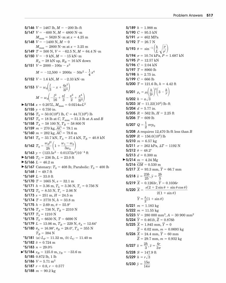
Problem Answers 517
5/1465/147
5/148
5/1495/150
5/151
5/152
5/153
5/1545/1555/1565/1575/1585/1595/1605/161
5/162
5/1635/1655/1665/1675/1685/1695/1705/1715/1725/1735/1745/1755/1765/1775/1785/1795/180
5/181 (a) , (b)5/1825/1835/1845/1855/1865/1875/188
5/1895/1905/1915/192
5/193
5/1945/1955/1965/1975/1985/1995/200
5/201
5/2025/2035/2045/2055/206
5/207
5/2085/2095/2105/2115/2125/2135/2145/2165/217
5/218
5/219
5/220
5/2215/2225/2235/2245/225
5/226
5/227
5/2285/229
5/230 y �15a14�
h � r�3S � 147.9 ft
x �2h3
, z �4r3�
Z � 29.7 mm, m � 0.932 kgX � 24.4 mm, Y � 60 mmZ � 6.02 mm, m � 0.0693 kgX � 1.845 mm, Y � 0Y � 0.461b, Z � 0.876bV � 280 000 mm3, A � 30 900 mm2m � 11.55 kgm � 1.183 kg
Y �s2(1 � sin �)
X �s(2 � 2 sin � � sin � cos �)
2(1 � sin �)
X � 0.1263r, Y � 0.1036r
x �23b25
, y �2b5
X � 93.3 mm, Y � 66.7 mmGM � 0.530 mm � 4.24 Mgd � 0.300 m� � 48.2�
� 262 kPa, �T � 1192 Nm � 6.57 kgR � 156.0(106) lbA requires 12,470 lb /ft less than B
Q �12
�rp0
T � 609 lbR � 562 lb, H � 2.25 ftd � 5.77 in.M � 11.22(104) lb-fth � a�3
�s � �l� h2r�
2�3 �hr�
T � 121.6 lb, h � 4.42 ftC � 666 lbh � 2.75 in.T � 8960 lbC � 2.04 kNP � 12.57 kN � 10.74 kPa, P � 1.687 kN
� � sin�1 �hL �
�
���T � 26.7 N � 462 MPaC � 95.5 kNh � 1.988 m
m � 90.2 kgr � 0.8, r � 0.577V � 5.71 m30.872 lb, 1 lbxB � 125.0 m, yB � �33.6 mn � 29.0% � 0.724 m
LC � 11.40 mLP � 11.32 mTB � 384 N�A � 16.98�, �B � 28.0�, TA � 355 NL � 13.06 m, TB � 229 N, �A � 12.64�
T0 � 6630 N, T � 6690 NT0 � 1210 NTA � 736 N, TB � 2310 Nh � 2.69 m, � � 55.9�
T � 3770 N, h � 33.8 ms � 251 m, H � 24.5 mTh � 8.53 N, Tv � 2.06 Nh � 3.36 m, Th � 3.36 N, Tv � 0.756 NT � 1665 N, s � 32.1 mL � 33.0 ftl � 49.7 ftCatenary: T0 � 408 lb; Parabolic: T0 � 400 lbL � 46.2 mTC � 236 lb, L � 23.0 fty � (123.5x2 � 0.01372x4)10�4 ft
T0 �w0l2
2h �1 �w1 � w0
3w0�
T0 � 33.7 kN, TA � 37.4 kN, TB � 40.8 kNm � 282 kg, AC � 79.6 mm � 270 kg, AC � 79.1 mTA � 58 100 N, TB � 58 800 NT0 � 18 lb at C, Tmax � 51.3 lb at A and BT0 � 50.0(106) lb, C � 44.7(106) lby � 0.750 in.x � 0.207L, Mmax � 0.0214wL2
M � w0��l2
16�
xl3
�x2
2�
x4
3l2�V � w0� l
3� x �
4x3
3l2�V � 1.6 kN, M � �2.33 kN � m
M � �12,500 � 2000x � 50x2 �14
x4
V � 2000 – 100x � x3RA � 28 kN up, RB � 16 kN downV � �9 kN, M � �15 kN � mT � 500 N, V � �62.5 N, M � 64.4 N � mMmax � 2800 N � m at x � 3.25 mV � �1400 N, M � 0Mmax � 5620 N � m at x � 4.25 mV � �600 N, M � 4800 N � mV � 1467 lb, M � �200 lb-ft
�
�
�
�
�
�
***
*
*
*
**
*****
****

518 Problem Answers
5/231
5/232
5/233
5/2345/2355/2365/2375/238
5/239
5/2405/2415/2425/2435/244
5/2455/2465/247
5/248Th � 10 N, Tv � 1.984 Nd � 197.7 m, horizontal thrusterTA � 175 800 N, TB � 169 900 Nsag � 3.98 m at 393 m right of A� � 8.63 kg/mXmax � 322 mm at x � 322 mmMmax � 9080 lb-ft at x � 9.63 ftVmax � 1900 lb at x � 0y � 3.74� � 46.8�
V � 0.931(106) lb, M � 2.21(108) lb-ftA � 1.440(106) lb, M � 7.78(108) lb-ft
P ��gab
6 �h �a2�
V � 2.8 kN, M � 6.53 kN � m, T � 1.867 kN � mM � �11.12 N � m, V � 55.6 NMmax � 186.4 N � m at x � 0.879 m, 5.12 mMmax � 500 lb-ft at x � 6 ftP � 348 kN
h �5H16
h �4H9
h �11H28
Chapter 6
6/16/26/36/4 (a)
(b)(c)
6/56/6 (a)
(b)6/76/86/96/106/11 (a)6/126/13 ,6/146/15
6/16
6/17
6/186/19 (a)6/20 (a) and (b)6/216/226/23 (a) (b)6/246/256/266/276/28
6/296/306/316/326/336/34
6/35
6/36
6/37 (a) (b)6/38
6/39
6/40
6/41
6/42
6/43
6/44 (a) (b)6/456/466/476/486/496/50
6/51 (a)(b)(c) �min � 10.30�, (�s)B � 0.0952
�min � 45�, (�s)B � 0.667�min � 61.2�, (�s)B � 1.667
R � 1291 lb(�s)min � 0.25 at A, (�s)min � 0.389 at B�s � 0.0824, 40.2 N�s � 0.761�s � 0.1264R � 8.81 kNP � 22.1 kN
� � 8.85�� � �8.02�,
P �Mrl � b
�s� e�
� � tan�1�mg sin �P �
P � mg��s2 cos2 � � sin2 �
� � 6.29�
2.37 �ld
� 8.14
x �a � b�s
2�s
�s � 0.268P � 109.1 NP � 24.5 N,
� � sin�1 3��s
4 – 3��s, �s �
23�
� � tan�1 ��a � b
a �20.5 � W � 112.9 lb� � 20.7�
F � 400 lbh � 156.6 mm, N � 1333 N�s � 0.1575�s � 0.287
�s � 0.365s � 2.55 m(a) 445 N, (b) 321 N3.05 � W � 31.7 lbM � 2.94 N � m
P � 36.8 lbP � 14.7 lb,� � 0.268M � 76.3 N � m
P � 19.2 lb� � 8.09�, (b) � � 26.2�
Slips first: a � �b; tips first: a � �b
�2 �m1
m1 � m2�1, �2 � 0.533
�s � 0.50: � � 40.9�
�s � 0.25: � � 61.8�
�s � 0.50: � � 45�
�s � 0.25: � � 63.4�
d � 0.2L� � 32.2��min � 0.630
M � 19.81 N � m� � 26.6�, (b) � � 18.43�, (c) � � 8.13�
� � 16.75�, P � 12 NFA � FB � 126.6 N, xmax � 86.2 mm�s � 0.1763�s � 0.0959, F � 0.0883mg, P � 0.1766mg
F � 40 lb upF � 46.4 lb up
Pslip � 0.448mg, Ptip � 0.536mgF � 148.5 NP � 516 NF � 66.0 N
� � 4.57�
F � 379 N left F � 85 lb left
�
***
*
**
*
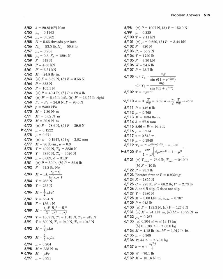
Problem Answers 519
6/526/536/546/556/566/576/586/596/606/616/626/636/646/656/666/676/686/696/706/716/726/736/746/756/766/776/786/796/80 ,6/816/82
6/83
6/846/85
6/86
6/876/88
6/89
6/906/91
6/92
6/93
6/946/956/966/97
6/986/996/1006/1016/1026/1036/1046/1056/1066/107
6/108 (a)
(b)
6/109
6/110
6/1116/1126/1136/1146/1156/1166/1176/1186/119
6/120
6/121
6/1226/123 Rotates first at 6/1246/1256/126 A and B slip, C does not slip6/1276/1286/1296/1306/1316/1326/133
6/1346/1356/136
6/137
6/1386/139 M � 10.16 N � m
W � 70.1 lb
b � a ��k
2d2
12.44 � m � 78.0 kg� � 0.368M � 4.12 lb-in., M� � 1.912 lb-in.(b) 0.1183 � m � 33.8 kg(a) 0.304 � m � 13.17 kg�s � 0.767(a) M � 24.1 N � m, (b) M � 13.22 N � m(a) F � 133.3 N, (b) F � 127.6 NP � 913 lbM � 3.00 kN � m, �min � 0.787T � 7980 N
C � 273 lb, F � 68.2 lb, P� � 2.73 lbR � 1855 N
P � 0.232mgP � 93.7 lb(b) F � 10 lb
(a) Tmax � 76.0 lb, Tmin � 24.0 lb
T ��gr
1 � �2�2�e��/2 � 1 � �2�T2 � T1e��/sin(�/2), n � 3.33 � � 0.1948x � 0.813 m� � 0.2148.66 � W � 94.3 lbh � 27.8 mmM � 1834 lb-in.� � 0.768P � 142.0 lb
� � 0: Tmg � 6.59, � l �
2: T
mg l e��B
T � mge��
Tb �mg
sin �(1 � e2��)
Ta �mg
sin �(1 � e�2��)
P � 23.7 lbW � 24.5 lbP � 3.30 kNT � 1720 lbPx � 55.2 NP � 320 N(a) � � 0.620, (b) P� � 3.44 kNT � 2.11 kN� � 0.228(a) P � 1007 N, (b) P � 152.9 N
� � 0.221M � �PrM � 335 N � m� � 0.204
M �25
�0La
M �58
�La
T � 899 N, T1 � 949 N, T2 � 1013 NT � 1069 N, T1 � 1013 N, T2 � 949 N
M �4�P
3Ro
3 � Ri3
Ro2 � Ri
2
F � 136.1 NT � 56.4 N
M �12
�PR
T � 233 NT � 258 N
M � �Lro � ri
ln(ro/ri)
P � 47.2 lb, No(a) P � 50 lb, (b) P � 52.9 lb
� � 31.3�� � 0.609T � 3830 N, T0 � 4020 NT � 4020 N, T0 � 3830 NM � 96 lb-in., � � 0.3(a) � � 0.1947, (b) rƒ � 3.82 mm� � 0.271� � 0.1222(a) P � 78.6 N, (b) P � 39.6 NM � 30.9 N � mM� � 3.02 N � mM � 7.30 N � mp � 2400 kPaFA � FB � 24.6 N, P � 98.6 N(a) P� � 6.45 lb left, (b) P� � 13.55 lb right(a) P � 49.4 lb, (b) P � 69.4 lbP � 105.1 NP � 333 N(a) F � 8.52 N, (b) F � 3.56 NM � 24.8 lb-in.P� � 3.51 kNP � 4.53 kNP � 449 N�s � 0.3, FA � 1294 N�s � 0.265NU � 53.5 lb, NL � 50.8 lbN � 5.66 threads per inch�s � 0.0262�s � 0.1763k � 20.8(103) N /m
�
�
�
*
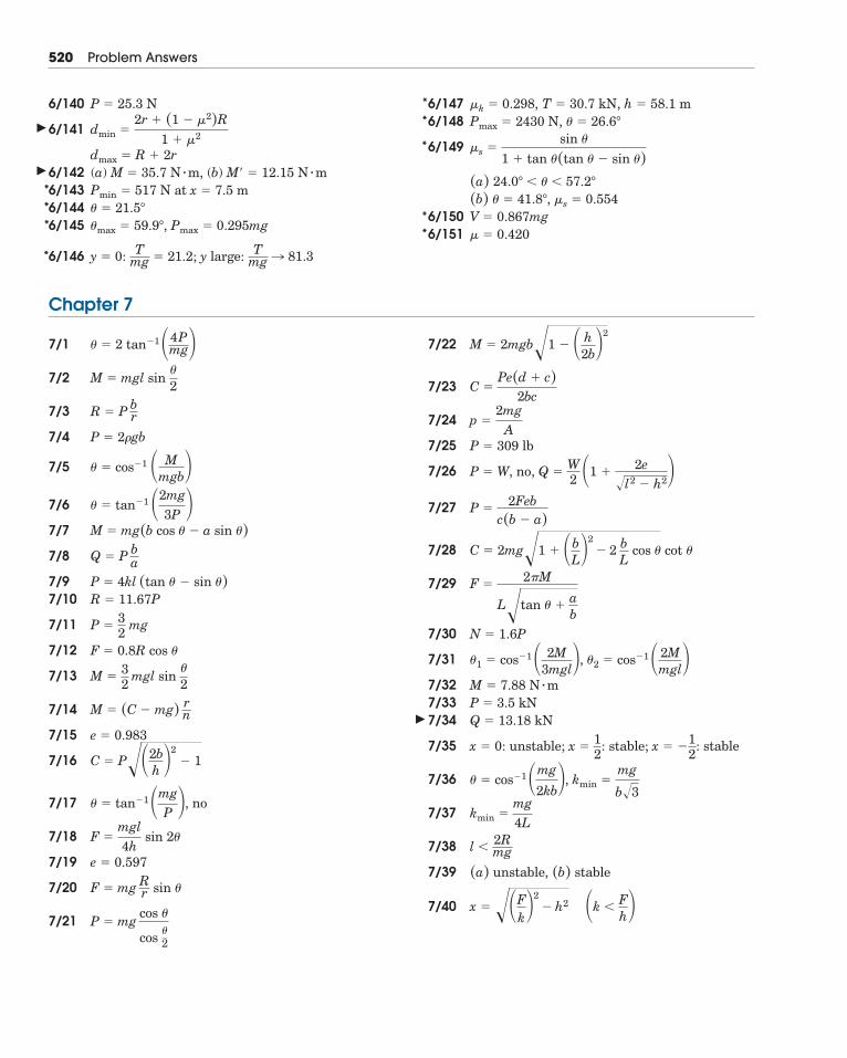
520 Problem Answers
6/140
6/141
6/1426/1436/1446/145
6/146
6/1476/148
6/149
6/1506/151 � � 0.420
V � 0.867mg(b) � � 41.8�, �s � 0.554(a) 24.0� � � � 57.2�
�s �sin �
1 � tan �(tan � � sin �)
Pmax � 2430 N, � � 26.6�
�k � 0.298, T � 30.7 kN, h � 58.1 m
y � 0: Tmg � 21.2; y large: T
mg l 81.3
�max � 59.9�, Pmax � 0.295mg� � 21.5�
Pmin � 517 N at x � 7.5 m(a) M � 35.7 N � m, (b) M� � 12.15 N � mdmax � R � 2r
dmin �2r � (1 � �2)R
1 � �2
P � 25.3 N
Chapter 7
7/1
7/2
7/3
7/4
7/5
7/6
7/7
7/8
7/97/10
7/11
7/12
7/13
7/14
7/15
7/16
7/17
7/18
7/19
7/20
7/21
7/22
7/23
7/24
7/25
7/26
7/27
7/28
7/29
7/30
7/31 ,
7/327/337/34
7/35
7/36
7/37
7/38
7/39
7/40 x � ��Fk�
2� h2
�k � F
h�(a) unstable, (b) stable
l � 2Rmg
kmin �mg4L
kmin �mg
b�3� � cos�1 �mg
2kb�,
x � 0: unstable; x �12
: stable; x � �12
: stable
Q � 13.18 kNP � 3.5 kNM � 7.88 N � m
�2 � cos�1 � 2Mmgl��1 � cos�1 � 2M
3mgl�N � 1.6P
F �2�M
L�tan � �ab
C � 2mg�1 � �bL�
2� 2
bL
cos � cot �
P �2Feb
c(b � a)
P � W, no, Q �W2
�1 �2e
�l2 � h2�P � 309 lb
p �2mg
A
C �Pe(d � c)
2bc
M � 2mgb�1 � � h2b�
2
P � mg
cos �
cos�2
F � mg
Rr sin �
e � 0.597
F �mgl4h
sin 2�
� � tan�1 �mgP �, no
C � P��2bh �2
� 1
e � 0.983
M � (C � mg)
rn
M �32
mgl sin �
2
F � 0.8R cos �
P �32
mg
R � 11.67PP � 4kl (tan � � sin �)
Q � P
ba
M � mg(b cos � � a sin �)
� � tan�1 �2mg3P �
� � cos�1 � Mmgb�
P � 2�gb
R � P
br
M � mgl sin �
2
� � 2 tan�1 �4Pmg�
***
*
**
*
**
�
�
�
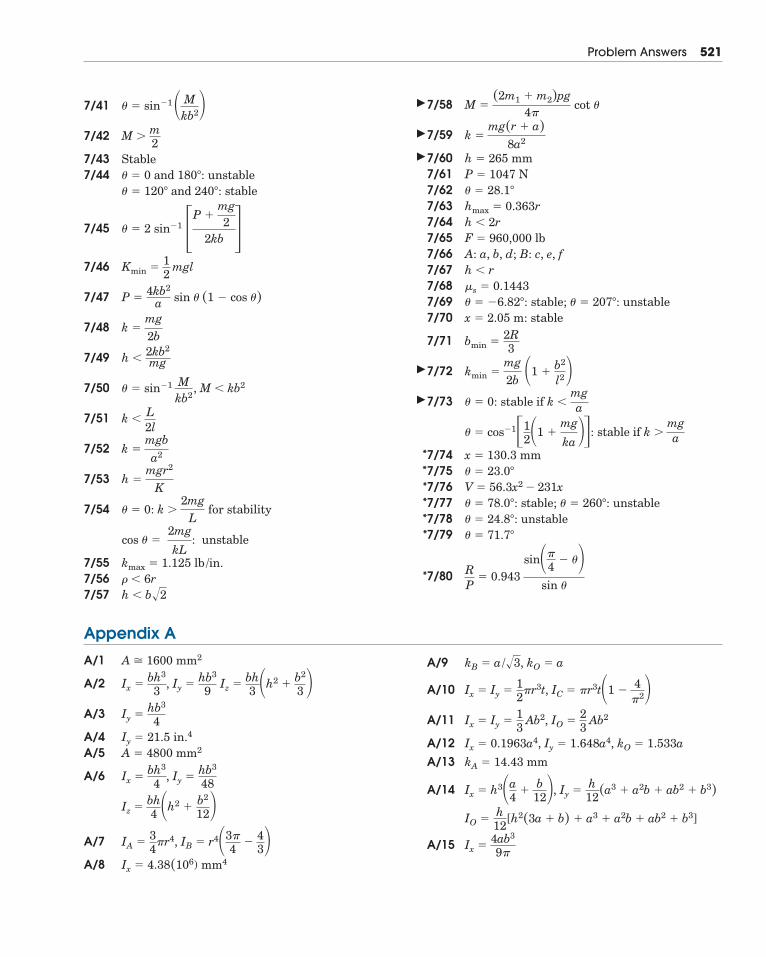
Problem Answers 521
7/41
7/42
7/437/44
7/45
7/46
7/47
7/48
7/49
7/50
7/51
7/52
7/53
7/54
7/557/567/57
7/58
7/59
7/607/617/627/637/647/657/667/677/687/697/70
7/71
7/72
7/73
7/747/757/767/777/787/79
7/80 RP
� 0.943 sin��
4� ��
sin �
� � 71.7�
� � 24.8�: unstable� � 78.0�: stable; � � 260�: unstableV � 56.3x2 � 231x� � 23.0�
x � 130.3 mm
� � cos�1�12�1 �
mg
ka ��: stable if k �mga
� � 0: stable if k �mga
kmin �mg2b �1 �
b2
l2�bmin �
2R3
x � 2.05 m: stable� � �6.82�: stable; � � 207�: unstable�s � 0.1443h � rA: a, b, d; B: c, e, fF � 960,000 lbh � 2rhmax � 0.363r� � 28.1�
P � 1047 Nh � 265 mm
k �mg(r � a)
8a2
M �(2m1 � m2)pg
4� cot �
h � b�2� � 6rkmax � 1.125 lb /in.
cos � �2mg
kL: unstable
� � 0: k �2mg
L for stability
h �mgr2
K
k �mgba2
k � L2l
� � sin�1
Mkb2
, M � kb2
h � 2kb2
mg
k �mg2b
P �4kb2
a sin � (1 � cos �)
Kmin �12
mgl
� � 2 sin�1 �P �mg2
2kb �� � 120� and 240�: stable� � 0 and 180�: unstableStable
M � m2
� � sin�1 � Mkb2�
Appendix A
A/1
A/2
A/3
A/4A/5
A/6
A/7 ,
A/8
A/9
A/10
A/11
A/12A/13
A/14
A/15 Ix �4ab3
9�
IO �h12
[h2(3a � b) � a3 � a2b � ab2 � b3]
Ix � h3�a4
�b
12�, Iy �h12(a3 � a2b � ab2 � b3)
kA � 14.43 mm
Ix � 0.1963a4, Iy � 1.648a4, kO � 1.533a
Ix � Iy �13
Ab2, IO �23
Ab2
Ix � Iy �12
�r3t, IC � �r3t�1 �4
�2�kB � a/�3, kO � a
Ix � 4.38(106) mm4
IB � r4�3�4
�43�IA �
34
�r4
Iz �bh4 �h2 �
b2
12�Iy �
hb3
48Ix �
bh3
4,
A � 4800 mm2Iy � 21.5 in.4
Iy �hb3
4
Ix �bh3
3, Iy �
hb3
9Iz �
bh3 �h2 �
b2
3 �A � 1600 mm2
�
�
�
�
�
******
*
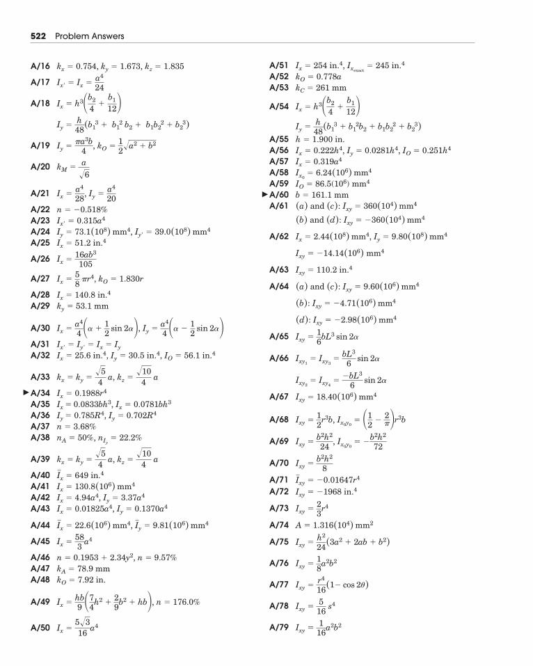
522 Problem Answers
A/16
A/17
A/18
A/19
A/20
A/21
A/22A/23A/24A/25
A/26
A/27
A/28A/29
A/30
A/31A/32
A/33
A/34A/35A/36A/37A/38
A/39
A/40A/41A/42A/43
A/44
A/45
A/46A/47A/48
A/49
A/50
A/51A/52A/53
A/54
A/55A/56A/57A/58A/59A/60A/61
A/62
A/63
A/64
A/65
A/66
A/67
A/68
A/69
A/70
A/71A/72
A/73
A/74
A/75
A/76
A/77
A/78
A/79 Ixy �1
16a2b2
Ixy �5
16s4
Ixy �r4
16(1� cos 2�)
Ixy �18
a2b2
Ixy �h2
24(3a2 � 2ab � b2)
A � 1.316(104) mm2
Ixy �23
r4
Ixy � �1968 in.4Ixy � �0.01647r4
Ixy �b2h2
8
Ixy �b2h2
24, Ix0y0
� �b2h2
72
Ixy �12
r3b, Ix0y0� �1
2�
2��r3b
Ixy � 18.40(106) mm4
Ixy2� Ixy4
��bL3
6 sin 2�
Ixy1� Ixy3
�bL3
6 sin 2�
Ixy �16
bL3 sin 2�
(d): Ixy � �2.98(106) mm4
(b): Ixy � �4.71(106) mm4
(a) and (c): Ixy � 9.60(106) mm4
Ixy � 110.2 in.4
Ixy � �14.14(106) mm4
Ix � 2.44(108) mm4, Iy � 9.80(108) mm4
(b) and (d): Ixy � �360(104) mm4
(a) and (c): Ixy � 360(104) mm4b � 161.1 mmIO � 86.5(106) mm4Ix0
� 6.24(106) mm4Ix � 0.319a4Ix � 0.222h4, Iy � 0.0281h4, IO � 0.251h4h � 1.900 in.
Iy �h48(b1
3 � b12b2 � b1b2
2 � b23)
Ix � h3�b2
4�
b1
12�kC � 261 mmkO � 0.778aIx � 254 in.4, Ixexact
� 245 in.4
Ix �5�316
a4
Ix �hb9 �7
4h2 �
29
b2 � hb�, n � 176.0%
kO � 7.92 in.kA � 78.9 mmn � 0.1953 � 2.34y2, n � 9.57%
Ix �583
a4
Ix � 22.6(106) mm4, Iy � 9.81(106) mm4
Ix � 0.01825a4, Iy � 0.1370a4Ix � 4.94a4, Iy � 3.37a4Ix � 130.8(106) mm4Ix � 649 in.4
kx � ky ��54
a, kz ��10
4a
nA � 50%, nIy� 22.2%
n � 3.68%Iy � 0.785R4, Iy � 0.702R4Ix � 0.0833bh3, Ix � 0.0781bh3Ix � 0.1988r4
kx � ky ��54
a, kz ��10
4a
Ix � 25.6 in.4, Iy � 30.5 in.4, IO � 56.1 in.4Ix� � Iy� � Ix � Iy
Ix �a4
4 �� �12
sin 2��, Iy �a4
4 �� �12
sin 2��ky � 53.1 mmIx � 140.8 in.4
Ix �58
�r4, kO � 1.830r
Ix �16ab3
105
Ix � 51.2 in.4Iy � 73.1(108) mm4, Iy� � 39.0(108) mm4Ix� � 0.315a4n � �0.518%
Ix �a4
28, Iy �
a4
20
kM �a�6
Iy ��a3b
4, kO �
12�a2 � b2
Iy �h48(b1
3 � b12 b2 � b1b2
2 � b23)
Ix � h3�b2
4�
b1
12�Ix� � Ix �
a4
24
kx � 0.754, ky � 1.673, kz � 1.835
�
�
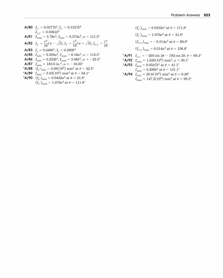
Problem Answers 523
A/80
A/81
A/82
A/83A/85A/86A/87A/88A/89A/90
A/91A/92A/93
A/94Imax � 147.2(106) mm4 at � � 99.3�
Imin � 20.8(106) mm4 at � � 9.26�
Imax � 0.286b4 at � � 131.1�
Imin � 0.0547b4 at � � 41.1�
Imax � 1.820(106) mm4, � � 30.1�
Ix�y� � �203 sin 2� � 192 cos 2�, � � 68.3�
(Ix�y�)max � 0.514a4 at � � 156.8�
(Ix�y�)min � �0.514a4 at � � 66.8�
(Iy�)max � 1.070a4 at � � 21.8�
(Iy�)min � 0.0432a4 at � � 111.8�
(Ix�)max � 1.070a4 at � � 111.8�
(Ix�)min � 0.0432a4 at � � 21.8�
Imin � 3.03(106) mm4 at � � 64.1�
(Ix�)min � 2.09(108) mm4 at � � 22.5�
Imax � 183.6 in.4, � � �16.85�
Imin � 0.252b4, Imax � 3.08b4, � � �22.5�
Imin � 0.505a4, Imax � 6.16a4, � � 112.5�
Ix � 0.446b4, Iy � 0.280b4
Ix� �r4
16(� � �3), Iy� �r4
16(� � �3), Ix�y� �r4
16
Imax � 3.79a4, Imin � 0.373a4, � � 111.5�
Ix�y� � 0.0361b4Ix� � 0.0277b4, Iy� � 0.1527b4
***
***
*
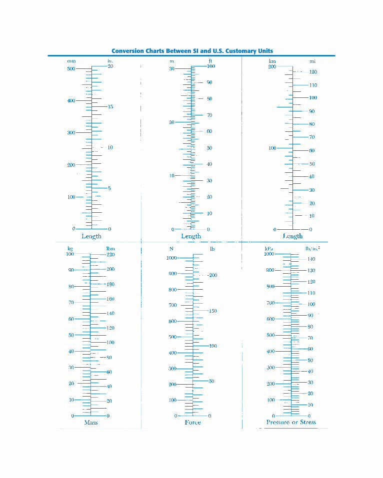
Conversion Charts Between SI and U.S. Customary Units
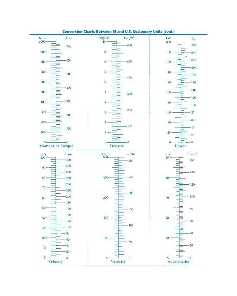
Conversion Charts Between SI and U.S. Customary Units (cont.)


![Static and Dynamic Analysis Web Opening of Steel Beams is the efficient design of beams girders with web opening. ... Redwood and Cho [5], ... investigation on steel beams with web](https://img.pdfslide.us/doc/110x75/5ac2ffa07f8b9a333d8b9788/static-and-dynamic-analysis-web-opening-of-steel-beams-is-the-efficient-design-of.jpg)


![Finite Element Modelling of Steel Beams with Web …... Darwin [4], Redwood and Cho [5], ... are possible for the design of steel and composite beams with web ... Steel beams with](https://img.pdfslide.us/doc/110x75/5ac2ffa07f8b9a333d8b9782/finite-element-modelling-of-steel-beams-with-web-darwin-4-redwood-and.jpg)