Embed Size (px)
Citation preview

102
CHAPTER6
EXPERIMENTAL DETAILS
This chapter presents the details of the main work of this project
which includes the design and experimentation to produce and
inspect the alloy steel castings. Further, an attempt is made to give
the complete details regarding the manufacturing process of Straight
and flanged bar casting from pattern making to the inspection. It
includes the properties of the material, composition, pouring
conditions, allowable process parameters, and finally the results and
their analysis.
6.1 STRAIGHT AND FLANGE BAR CASTINGS
In this present work, straight and flanged bar castings are
produced with different weights. These castings are in small weight
category, as can be seen from Fig:6.1. For analyzing the defects
occurring in this casting, it is necessary to know the actual processing
conditions; gating design (which can be seen in Fig:6.2), etc.. The
manufacturing details of this casting are given below in detail.
1. Material: Alloy steels 2. Grade: 25
3. Casting weight: 50 Kg 4. Bunch weight: 80 Kg
5. Pattern material: Teak wood 6.Moisture Content: 3.6 – 4.0%
7. Permeability: 120 – 160, 8.Compactability: 42 -50

103
9. Mould Hardness: center / edge-: 80 / 85 -90 /80.
10.Silica sand: 45 -50 %
11. Silica sand: 50 – 60 % 12.Active clay: 8 – 9 %
13. Versatile matter: 3.5 – 4.5 %
Fig:6.1Straight bar casting. Fig:6.2 Flanged bar casting.
6.1.1 Production of Castings
Experiments were conducted to verify the use of simulation in
an industry casting environment. The selected Castings were straight
and flanged bar made from Alloy steels (IS1030 and IS2644 their
chemical composition and Mechanical properties are shown in the
tables 6.1, 6.2 and table 6.3, and 6.4 respectively). The tests
conducted in this experiments used to find potential defects in the
casting models with different criterions and compare them with the
real casting design and to find possible outcomes to modifications
attempted to improve the existing casting design. The Riser Design
and Gating Design were also used to try to improve the existing
casting design and develop riser and gating systems for the casting.
Details of the riser and gating system design are furnished in
Appendix B. from scratch and compare the calculated dimensions and
resulting simulations with the existing casting design.

104
Table: 6.1Cast Steel IS 1030
Grade C Si Mn P S Cr Ni Mo Cu V
200-
400W
0.25 0.60 1.00 0.040 0.035 0.35 0.40 0.15 0.40 0.05
Table: 6.2 Mechanical Properties
Grade Tensile Strength MPa min.
Yield Stress MPs Min.
Elongation Percent
Min.
Reduction of Area Percent
Min.
Impact Strength J Min.
Angle of Bend
Degrees Min.
200-400W
400 200 25 40 45 90
Table: 6.3 Cast Steel IS 2644
Grade C Si Mn P S Cr Ni Mo Cu V
200-
400W
0.25 0.3-
0.5
1.1-
1.4
0.035 0.035 0.5 0.40 0.15 0.40 0.05
105
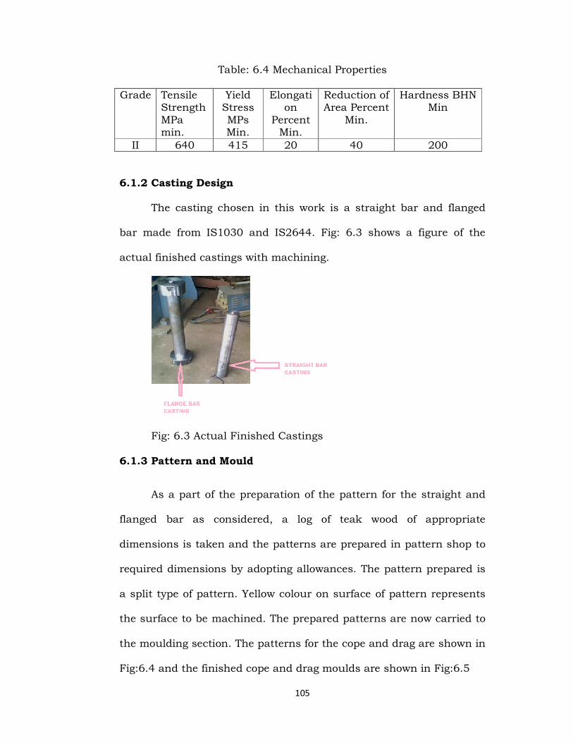
Table: 6.4 Mechanical Properties
Grade Tensile Strength MPa min.
Yield Stress MPs Min.
Elongation
Percent Min.
Reduction of Area Percent
Min.
Hardness BHN Min
II 640 415 20 40 200
6.1.2 Casting Design
The casting chosen in this work is a straight bar and flanged
bar made from IS1030 and IS2644. Fig: 6.3 shows a figure of the
actual finished castings with machining.
Fig: 6.3 Actual Finished Castings
6.1.3 Pattern and Mould
As a part of the preparation of the pattern for the straight and
flanged bar as considered, a log of teak wood of appropriate
dimensions is taken and the patterns are prepared in pattern shop to
required dimensions by adopting allowances. The pattern prepared is
a split type of pattern. Yellow colour on surface of pattern represents
the surface to be machined. The prepared patterns are now carried to
the moulding section. The patterns for the cope and drag are shown in
Fig:6.4 and the finished cope and drag moulds are shown in Fig:6.5

106
Fig:6.4split piece pattern left and Full pattern Right side
Fig: 6.5 The Cope Mould Right and Drag Mould Left side
6.1.4 Mould preparation
The sand of prescribed grain size of 60 GFN (250microns) is
taken and is added with silicate oil of standard proportion and is
placed in Muller machine for the perfect mixing. This is essential to
ensure uniform distribution of various components in enter bulk of
the sand. The mostly commonly used Muller machine consists of two
Muller wheels in equal number of plough blades all of them connect to
a single drive source. The Muller wheels are large and heavy and they
continuously roll inside the Muller bowl. The plough blades ensure the
sand is continuously agitated. The combined action makes the silicate
oil is distributed uniformly throughout the sand. The composition of
the sand and the oil is given in the Table: 6.5

107
TABLE: 6.5 Moulding Sand Composition
SILICA SAND(in kgs) SILICATE OIL(in kgs)
250 1
The quartz sand is also mixed with silicate oil with
certain compositions and is placed in the Muller machine. To increase
the collapsibility of the sand. Iron oxide powder, Silicon oxide powder
& O3 powder are also added to sand. Iron Oxide powder is added to
increase hot strength. The perfectly mixed Quartz sand which is in
pink colour is obtained due to the adding of certain composition of
Red oxide to it for easy identification. The Quartz sand as high
refractiveness & bonding. Hence it is used as facing sand especially in
pattern contact area. For roughly 3 to 4 inches & then the silica sand
is used besides the Quartz sand to make cost reduction, hence it
known as back up sand. The uniformly mixed sand is placed in mould
box around the patterns of straight and Flanged bar which consists
of the replica of the accurate dimensions of the sprue and gate, as
shown in Fig:6.6 For the present work, CO2 sand moulding technique
is chosen.

108
Fig:6.6 shows the dimensions of the gating system.
6.1.5 CO2 Moulding Process
The principle of working of the CO2 process is based
on the fact that if co2 gas is passed through a sand mix containing
sodium silicate as the binder, immediate hardening of sand takes
place as a result of the chemical action between sodium silicate and
CO2.The bonding strength obtained by the hardening action is
sufficient to eliminate baking or drying of the mould and the metal
can be immediately poured. The chemical reactions taking place are of
complex nature, though the main reaction can be represented in
simplified form as:
Na2O. mSiO2. xH2O + CO2 Na2CO3 + mSiO2 .xH2O
The SiO2 obtained from the reaction contains a certain number
of water molecules and is represented as SiO2.xH2O, which is called
silica gel. This silica gel is responsible for giving the necessary
strength to the mould. The CO2 gas is passed through the mould for
5minutes to obtain required hardness. Now the patterns from the
mould are removed.

109
6.1.6 Assembled Mould
After preparation of cope and drag boxes, the cope is placed on
top of the drag and then the molten metal is poured into the mould
through the sprue at 15500C with a super heat of 250C. The top open
riser is covered with magnesium based exothermic top to keep the
riser hot and feed the casting for an extended period of time. Fig:6.7
shows an assembled mould filled with liquid metal and top risers
covered with the exothermic insulation. The exothermic insulation
would be approximately 1.25 inches thick. The castings were then
stripped out of mould after 24 hours of pouring.
Fig:6.7 Pouring of liquid metal in to the Mould.
Entire work was carried in seven trials, the typical Auto Cad models
for Trial 1 is as shown in Fig 6.8 and that for Trial 2 which consists
of a modified gating system as per calculations is as shown in Fig:6.9.

110
Fig:6.8 Casting with initial gating Fig:6.9 casting with modified-
-gating system
6.2 CASTINGS PREPARATION FOR NDT EXAMINATION:
The castings after allowing cooling for 24 hours are then taken
to fettling section where they are stripped off from the moulds by
destroying the moulds. The straight bar casting after removing from
the mould is as shown in Fig:6.10. The casting now is knocked and
fettled as shown in Fig:6.11. The castings are now carried to grinding
section located just besides the fettling section. In grinding process
any unwanted extra metal is removed from the casting as shown in
Fig:6.12. Once the casting is ground it is carried to machine shop
where it is machined to required dimensions. The machining process
is carried out on a lathe machine as shown in Fig:6.13. The machined
casting is now ready for testing as shown in Fig:6.14.

111
Fig:6.10 Casting with runner and feeders Fig:6.11Straight bar after
fettling
Fig: 6.12 Grinding of the casting Fig:6.13 Machining of the casting
Fig: 6.14 Machined casting ready for testing

112
6.3 INSPECTION AND TESTING OF CASTINGS
After simulation trials, alloy steel castings are produced with same
composition, and geometry, as per the conditions taken up in
simulation. This testing is used to validate the results of simulation
process.
The following widely used non-destructive tests are conducted
as per requirements of the case study unit.
(1) Visual inspection; (2) Fluorescent dye penetrant inspection;
(3) Magnetic particle inspection; (4) Ultrasonic test.
6.3.1 Visual Inspection :
Castings are subjected to a visual inspection to ensure that the
external surface that fail to meet the customer and manufacturer
requirements. Visible defects that can be detected provide a means for
discovering errors in the pattern or in the moulding, and casting
process. In the present study large blow holes formed in the castings
prepared for trail 1 is as shown in Fig:6.15
Fig: 6.15 defects that can be identified by Visual Inspection

113
6.3.2 Liquid dye penetrant test:
Penetrant testing helps to detect small discontinuities such as
shrinkage, porosity and cracks open to the surface which tend to
retain penetrant. Smooth or machined casting surface provide more
satisfactory conditions for the test.
universal testing procedure:
1.Clean the surface of the tested casting free of dust and dirt with the
help of piece of cloth
2. Brush the surface of the casting to remove scale, paint, rust etc., by
a soft brush
3. Spray the cleaner to remove oil, grease, etc.,
4. Apply the dye penetrant by spraying allow 3 to 5 minutes for dye to
penetrant into the cracks.
5. Again spray the surface with the cleaner to remove the excess dye.
6. Spray the developer on the surface to give a thin layer. This layer
absorbs the penetrant from the cracks and red spots appear on the
surface to give a visible indication of the defects.
The liquid pentrant process as mentioned above is carried out as
shown in Fig:6.16(a) & Fig:6.16(b)
Fig: 6.16(a) Liquid Pentrant testing process

114
Fig: 6.16(b) Liquid Pentrant testing process
6.3.3 Magnetic Particle Inspection:
This method of inspection is used on magnetic ferrous castings for
detecting invisible surface or slightly subsurface defects. Deeper
subsurface defects are not satisfactorily detected because the
influence of the distorted lines of magnetic flux on the magnetic
particles spread over the casting surface becomes weaker with the
distance, so that sensitivity falls away rapidly with the depth.
Procedure: The steps involved in testing are as follows.
1. Magnetising the component
2. Applying magnetic particles on the component
3. Locating the defects.
The magnetic particle testing process is carried out and it was shown
in the Fig:6.17

115
Fig:6.17 Magnetic Particle testing process
6.3.4 Ultrasonic Testing:
Ultrasonic Testing used to detect internal defects in castings, based
on principle of reflection of high frequency sound waves. If surface
under testing contains some defect, the high frequency sound wave,
when emitted through the casting, will be reflected from the surface of
the defect and return in a shorter period of time. For detecting the
length of time, an oscillograph is used. The path of travel of sound
wave is plotted on the C.R.T. Screen of the oscillograph where it can
also be measured.The ultrasonic testing process is carried out as
shown in Fig.6.18 to Fig.6.21.
Fig:6.18 ultrasonic Inspection Fig:6.19 ultrasonic Inspection.

116
Fig:6.20 Inspection of the straight bar Fig:6.21 Inspection of flange.
Fig:6.18 to 6.21 shows the ultrasonic Inspection of the straight bar
and flanged bar produced an indication which confirmed the
shrinkage defect at flanged bar end.
6.4 EXPERIMENTAL OBSERVATIONS:
Straight and Flanged bar castings have been produced in
foundry with cast metals as IS1030,IS2644and CO2 sand as mould
material. The experimental observations made on straight and the
flanged bar castings were found to be in correlation with that
predicted by using ProCAST simulation. Blow holes were observed on
the straight bar near the flanges on both sides as predicted by
simulation, porosity was also observed as predicted from the
simulation results.
Using the results of computer simulation, foundry tooling and
prototype castings were made, NDT,and mechanical tests as well as
metallographic examinations of the heat treated IS 1030 and IS2644
alloy steel castings were carried out. results of investigations, a

117
satisfactory quality of the new range of castings has been stated, and
obtaining of the required mechanical parameters was confirmed.
Fig: 6.22 Blow holes on straight bar Fig: 6.23 Blow holes near
flanges
Fig: 6.24 Surface defect on flanges
With the help of die penetrant test surface pin holes and surface
cracks were observed in the flanged bar when riser is not present were
shown in Fig.6.22-6.24. Sand inclusion was observed on one of the
flanges which were not present in the results of simulation; this may
be because of the variation in case of experimental conditions when
compared to conditions under which simulation is carried out.

118
6.5. RESULTS
In visual inspection method we can find the macro defects
like large blow holes obtained in the flanged bar prepared from thumb
rules as shown in above figure. The casting thus obtained is directly
rejected because of such large blow holes. The dimensions of the
casting are also measured in the visual inspection testing. The next
NDT method is liquid pentrant testing method; in this method of
testing, the castings prepared were observed for any surface pinholes
and surface cracks. However the casting with very few pinholes is not
rejected and it is repaired through welding techniques, and the
casting is accepted. With the help of liquid pentrant test, we can only
find the surface defects. Magnetic particle testing is one of the
economic non destructive tests; in this method we are able to find the
cracks on the surface which are very thin and almost of negligible
thickness. It is also used to find surface defects and it is more
accurate and economical compared to liquid pentrant test. Similarly,
liquid pentrant test was carriedout and it is observed that the straight
and flanged bar castings found some pinhole defects as shown in
Figures 6.25 and 6.26.
Fig:6.25: pin holes straight bar Fig:6.26: pin holes on flange end
119
Fig:6.25 & Fig:6.26 shows the Liquid Penetrant Inspection of the
straight bar and flanged bar produced an indication which
confirmed the suspected pin holes.
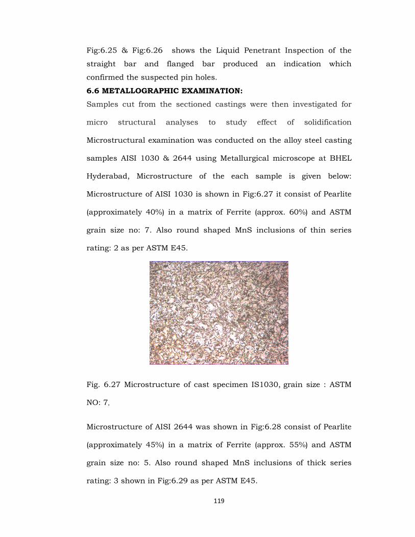
6.6 METALLOGRAPHIC EXAMINATION:
Samples cut from the sectioned castings were then investigated for
micro structural analyses to study effect of solidification
Microstructural examination was conducted on the alloy steel casting
samples AISI 1030 & 2644 using Metallurgical microscope at BHEL
Hyderabad, Microstructure of the each sample is given below:
Microstructure of AISI 1030 is shown in Fig:6.27 it consist of Pearlite
(approximately 40%) in a matrix of Ferrite (approx. 60%) and ASTM
grain size no: 7. Also round shaped MnS inclusions of thin series
rating: 2 as per ASTM E45.
Fig. 6.27 Microstructure of cast specimen IS1030, grain size : ASTM
NO: 7,
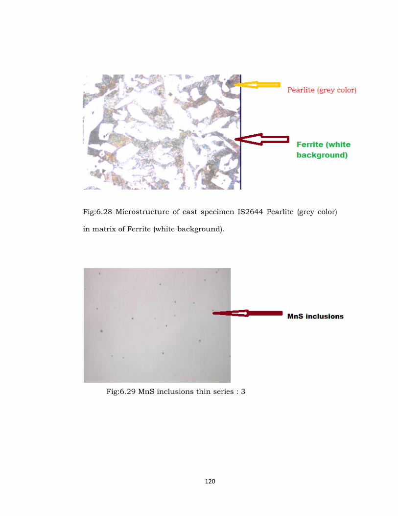
Microstructure of AISI 2644 was shown in Fig:6.28 consist of Pearlite
(approximately 45%) in a matrix of Ferrite (approx. 55%) and ASTM
grain size no: 5. Also round shaped MnS inclusions of thick series
rating: 3 shown in Fig:6.29 as per ASTM E45.
120
Fig:6.28 Microstructure of cast specimen IS2644 Pearlite (grey color)
in matrix of Ferrite (white background).
Fig:6.29 MnS inclusions thin series : 3

121
6.7 CONCLUSIONS AND REMARKS:
From the previous sections it is quite obvious that the main purpose
of nondestructive testing is to determine the correctness of a
particular part or a system to agreeably perform its intended function.
With this purpose, the field of nondestructive testing can be a
significant contributor to increased efficiency and utilization of
machines and materials as well as a key item in assure safe routine.
Limits of defect detect ability are of serious concern to both
manufacturers and users of castings. Due to the complex nature of
castings and the casting process, it is difficult to set definite rules for
inspection systems to detect sub-surface defects. Hence, the thrust of
this present work was to investigate, within the specified domain, the
possibility of detecting sub-surface gas porosity defects in alloy steel
sand castings with rough surfaces. The experimental results were
used as a framework in building an inspection procedure for alloy
steel sand castings.